

Toyota Prius: Airbag System
- Precaution
- Parts Location
- System Diagram
- System Description
- How To Proceed With Troubleshooting
- Operation Check
- Utility
- Problem Symptoms Table
- Terminals Of Ecu
- Freeze Frame Data
- Check Mode Procedure
- Data List / Active Test
- How To Connect Or Disconnect Airbag Connector
- Diagnostic Trouble Code Chart
- Vehicle Control History
- VEHICLE CONTROL HISTORY (RoB)
- Driver Frontal Stage 1 Deployment Control Circuit Short to Ground (B000111)
- Driver Frontal Stage 2 Deployment Control Circuit Short to Ground (B000211)
- Driver Knee Bolster Deployment Control Circuit Short to Ground (B000411)
- Driver Knee Bolster Deployment Control Circuit Short to Battery (B000412)
- Driver Knee Bolster Deployment Control Circuit Open (B000413)
- Driver Knee Bolster Deployment Control Circuit Resistance Below Threshold (B00041A)
- Passenger Frontal Stage 1 Deployment Control Circuit Short to Ground (B001011)
- Passenger Seat Belt Sensor Circuit Undetermined Failure (B005200)
- Passenger Seat Belt Sensor Circuit Short to Ground (B005211)
- Passenger Seat Belt Sensor Circuit Open (B005213)
- Left Frontal Restraints Sensor Value of Signal Protection Calculation Incorrect (B009083)
- Left Frontal Restraints Sensor Missing Message (B009087)
- Right Side Restraints Sensor 5 Signal Plausibility Failure (B009E64)
- Restraint System Malfunction Indicator 1 Circuit Short to Battery (B00D212)
- Restraint System Malfunction Indicator 1 Circuit Short to Ground or Open (B00D214)
- Airbag ECU (Microcomputer) Internal Electronic Failure (B116049,...,P05BB00)
- Right Side Restraints Sensor 5 / Left Side Restraints Sensor 5 Signal Compare Failure (B166A62)
- Lost Communication with Brake System Control Module "A" Missing Message (U012987,U023A87)
- SRS Warning Light Remains ON
- SRS Warning Light does not Come ON
Precaution
PRECAUTION
CAUTION:
- Failure to carry out service procedures in the correct sequence could cause SRS parts to unexpectedly deploy and possibly lead to serious injuries. Furthermore, if a mistake is made when servicing SRS parts, they may fail to operate when required. Before performing servicing (including installation/removal, inspection and replacement of parts), be sure to read the following precautions.
-
Be sure to perform initialization of the airbag ECU assembly under any of the following conditions. If initialization is not performed, the SRS may not operate properly.
- The airbag ECU assembly is replaced.
- Accessories (seatback tray, seat cover, etc.) are installed or removed.
- The front passenger seat is removed from the Toyota Prius vehicle.
- Any of the bolts that are used to install the front passenger seat are removed and reinstalled.
- The passenger airbag ON/OFF indicator ("ON") illuminates when the front passenger seat is not occupied or the airbag OFF indicator illuminates when the front passenger seat is occupied (by an adult).
- An occupant classification sensor collision detection DTC is output due to an accident or a collision.
(a) Furthermore, if a mistake is made when servicing SRS parts, they may fail to operate when required. Before performing servicing (including installation/removal, inspection and replacement of parts), be sure to read the following precautions.
- Airbag ECU assembly
- Front airbag sensor
- Side airbag pressure sensor
- Floor side airbag sensor
- Horn button assembly
- Lower No. 1 instrument panel airbag assembly
- Instrument panel passenger airbag assembly
- Curtain shield airbag assembly
- Front seat airbag assembly
- Rear seat airbag assembly
- Front seat outer belt assembly
- Rear seat outer belt assembly
PRECAUTION FOR DISCONNECTING CABLE FROM NEGATIVE AUXILIARY BATTERY TERMINAL
(a) When troubleshooting the SRS, always check for DTCs before disconnecting the cable from the negative (-) auxiliary battery terminal.
(b) After turning the ignition switch off, disconnect the cable from the negative (-) auxiliary battery terminal.
NOTICE:
After the ignition switch is turned off, there may be a waiting time before disconnecting the negative (-) auxiliary battery terminal.
Click here

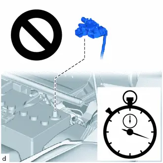
(c) Before starting work relating to the SRS airbag system, fitting adjustment of the front/rear doors and removal, installation or replacement of parts near the airbag sensors, wait for at least 60 seconds after disconnecting the cable from the negative (-) auxiliary battery terminal.
CAUTION:
The SRS is equipped with a back-up power source. If work is started within 60 seconds of disconnecting the cable from the negative (-) auxiliary battery terminal, the SRS parts may deploy.
HINT:
When disconnecting and reconnecting the battery, there is an automatic learning function that completes learning when the respective system is used.
Click here


GENERAL PRECAUTION
(a) Information labels are attached to the SRS parts. Follow the instructions on the labels.
(b) Never disassemble or attempt to repair any of the SRS parts.
(c) If any of the SRS parts are dropped, or if any cracks, dents or other defects are found, replace them with new parts.
(d) Never use airbags and pretensioners from another Toyota Prius vehicle. When replacing parts, use new parts.
(e) Do not expose any of the SRS parts directly to high temperatures or flames.
(f) If the vehicle has been involved in a minor collision where the SRS did not deploy, the airbags and pretensioners should be inspected before further use of the vehicle.
(g) Do not apply grease, detergent, oil or water to the SRS parts. If applied, immediately wipe it off with a dry cloth.
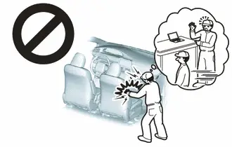
(h) When deploying or storing the SRS parts, avoid places with a high temperature and high humidity, and keep them away from electrical noise.
(i) Do not stack or place anything on top of the airbags and pretensioners.
CAUTION:
Dispose of the airbags according to the disposal procedures for each airbag.
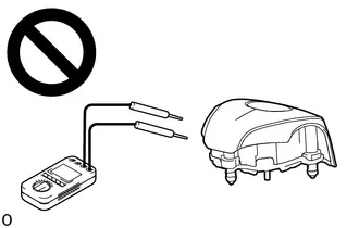
(j) Never measure the resistance of the airbags and pretensioners.
CAUTION:
Never measure the resistance of the airbags and pretensioners because current from the tester may cause the airbags and pretensioners to deploy.

(k) Use a voltmeter/ohmmeter with high impedance (minimum = 10 kΩ) for troubleshooting electrical circuits.
(l) Be sure to check the SRS warning light and multi-information display after checking, removing and installing, or replacing the airbag and sensor.
PRECAUTION FOR AIRBAG ASSEMBLIES
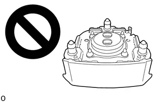
(a) Keep the deployment side of an airbag facing upward even when the airbag is temporarily removed during service.
CAUTION:
Always place a removed or a new airbag with the deployment side facing upward. Placing the airbag with the deployment side facing downward could cause a serious accident if the airbag deploys.
(b) When storing the airbag, do not place anything on top of the airbag or pile up airbags.
PRECAUTION FOR FRONT SEAT OUTER BELT ASSEMBLY (PRETENSIONER) AND REAR SEAT OUTER BELT ASSEMBLY (PRETENSIONER)
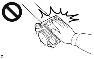
(a) Do not touch the area around the retractor even when the front seat outer belt assembly or rear seat outer belt assembly is temporarily removed during service.
CAUTION:
If the pretensioner unexpectedly deploys and the front seat outer belt assembly or rear seat outer belt assembly is retracted during an operation, it could cause a serious accident.
(b) When storing the pretensioner, do not place objects on top of the pretensioner or pile up pretensioners.
PRECAUTION FOR SPIRAL CABLE WITH SENSOR SUB-ASSEMBLY
(a) Do not replace the spiral cable with sensor sub-assembly with the auxiliary battery connected and the ignition switch ON.
(b) Do not rotate the spiral cable with sensor sub-assembly without the steering wheel assembly installed, with the auxiliary battery connected and the ignition switch ON.
(c) Ensure that the steering wheel assembly is installed and aligned straight when inspecting the steering sensor.
(d) When rotating the spiral cable with sensor sub-assembly, make sure to push on the interlock to release the interlock mechanism.
(e) Do not remove the steering angle sensor from the spiral cable with sensor sub-assembly without using the lock pin, as this may shift the center point of the steering angle sensor.
(f) Be sure that the spiral cable with sensor sub-assembly is in the neutral position during installation and when removing and installing the steering wheel assembly.
NOTICE:
If the steering wheel assembly is turned without the spiral cable with sensor sub-assembly installed in the neutral position, the cable may break.
PRECAUTION FOR AIRBAG ECU ASSEMBLY AND AIRBAG SENSORS
(a) When the airbags and pretensioners are deployed (including when only an airbag or pretensioner is deployed) due to a collision, be sure to replace all sensors in the damaged areas (anywhere in need of repair) and the airbag ECU assembly.
(b) Visually check the airbag sensors in undamaged areas for defects.
(1) The defects are as follows:
- Cracks in the sensor housing
- Dents in the sensor housing
- Chips in the sensor housing
- Cracks or other damage to the connector
- Damage to the serial number
(c) When removing and installing the airbag ECU assembly, front airbag sensor, side airbag pressure sensor and floor side airbag sensor connectors, be sure to perform work with the sensors installed to the Toyota Prius vehicle.
(d) Do not use a sensor if dropped during operation.
(e) Do not use a sensor if subjected to any strong impact.
(f) Never disassemble any of the SRS parts.
PRECAUTION FOR SIDE AIRBAG PRESSURE SENSOR
(a) Do not make any modifications to the front door that may change the inner pressure of the front door.
(b) Do not allow any foreign matter to enter the side airbag pressure sensor as it may affect the pressure detection performance of the sensor.
(c) When painting the front door, remove or apply protective tape to the side airbag pressure sensor to prevent paint from attaching to it.
(d) Make sure that the parts which maintain the sealing performance of the front door are securely installed. If the sealing performance of the front door decreases, the pressure detection performance of the side airbag pressure sensor may be affected. Repair or replace parts as necessary.
PRECAUTION FOR WIRE HARNESS AND CONNECTOR
(a) All wire harnesses except unexposed harnesses in the engine compartment are colored yellow.
(b) As special connectors are used, be careful when handling them.
PRECAUTION FOR DAMAGED Toyota Prius Vehicle
(a) Before using an electric welder on the vehicle, remove any airbags and pretensioners around the area being repaired.
(b) Before repairs, remove the airbag sensor assemblies if impacts are likely to be applied to the sensor during repairs.
(c) Never expose an airbag sensor directly to high temperatures.
(d) As the airbags and pretensioners are very hot after being deployed, ensure that all wire harnesses and connectors around deployed SRS parts are not damaged.
Parts Location
PARTS LOCATION
ILLUSTRATION
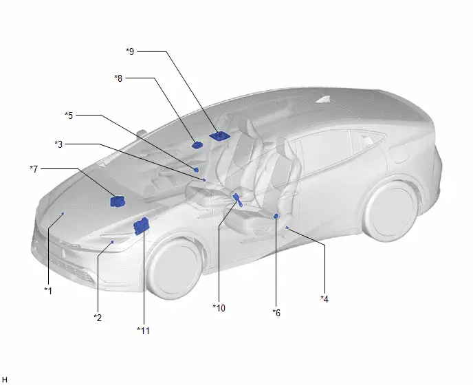
| *1 | FRONT AIRBAG SENSOR RH | *2 | FRONT AIRBAG SENSOR LH |
| *3 | FLOOR SIDE AIRBAG SENSOR RH | *4 | FLOOR SIDE AIRBAG SENSOR LH |
| *5 | SIDE AIRBAG PRESSURE SENSOR RH | *6 | SIDE AIRBAG PRESSURE SENSOR LH |
| *7 | BRAKE ACTUATOR ASSEMBLY - NO. 2 SKID CONTROL ECU | *8 | FORWARD RECOGNITION CAMERA |
| *9 | MAP LIGHT ASSEMBLY (w/ Occupant Classification System) - PASSENGER AIRBAG ON/OFF INDICATOR | *10 | FRONT SEAT INNER BELT ASSEMBLY RH (w/ Occupant Classification System) - PASSENGER SEAT BUCKLE SWITCH |
| *11 | ECM | - | - |
ILLUSTRATION
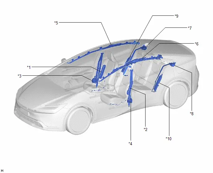
| *1 | FRONT SEAT AIRBAG ASSEMBLY RH | *2 | FRONT SEAT AIRBAG ASSEMBLY LH |
| *3 | FRONT SEAT OUTER BELT ASSEMBLY RH | *4 | FRONT SEAT OUTER BELT ASSEMBLY LH |
| *5 | CURTAIN SHIELD AIRBAG ASSEMBLY RH | *6 | CURTAIN SHIELD AIRBAG ASSEMBLY LH |
| *7 | REAR SEAT OUTER BELT ASSEMBLY RH | *8 | REAR SEAT OUTER BELT ASSEMBLY LH |
| *9 | REAR SEAT AIRBAG ASSEMBLY RH (w/ Occupant Classification System) | *10 | REAR SEAT AIRBAG ASSEMBLY LH (w/ Occupant Classification System) |
ILLUSTRATION
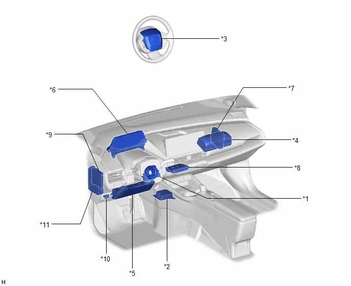
| *1 | SPIRAL CABLE SUB-ASSEMBLY | *2 | AIRBAG ECU ASSEMBLY |
| *3 | HORN BUTTON ASSEMBLY | *4 | INSTRUMENT PANEL PASSENGER AIRBAG ASSEMBLY |
| *5 | LOWER NO. 1 INSTRUMENT PANEL AIRBAG ASSEMBLY (w/o Occupant Classification System) | *6 | COMBINATION METER ASSEMBLY - SRS WARNING LIGHT |
| *7 | HYBRID Toyota Prius Vehicle CONTROL ECU | *8 | DCM (TELEMATICS TRANSCEIVER) (w/ Manual (SOS) Switch) |
| *9 | MAIN BODY ECU (MULTIPLEX NETWORK BODY ECU) | *10 | DLC3 |
| *11 | POWER DISTRIBUTION BOX ASSEMBLY - A/BAG-IGR FUSE - METER-IGR FUSE - ECU-IGR NO. 3 FUSE (w/ Occupant Classification System) | - | - |
System Diagram
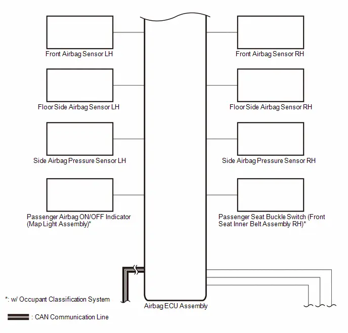
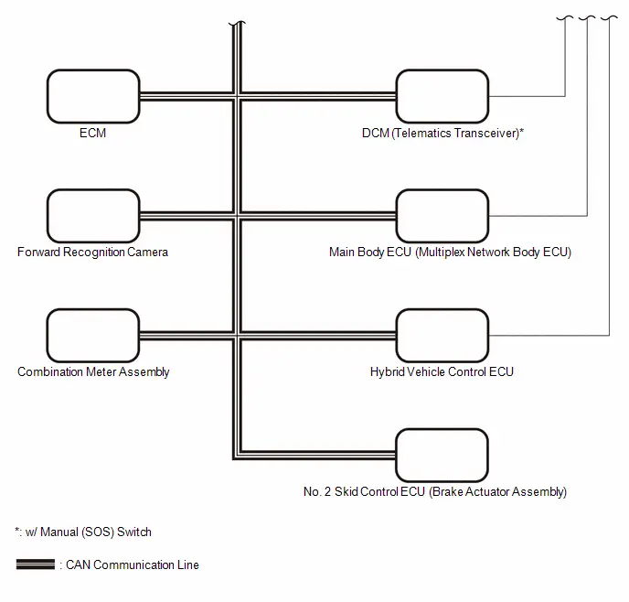
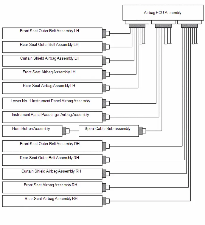
SYSTEM DIAGRAM
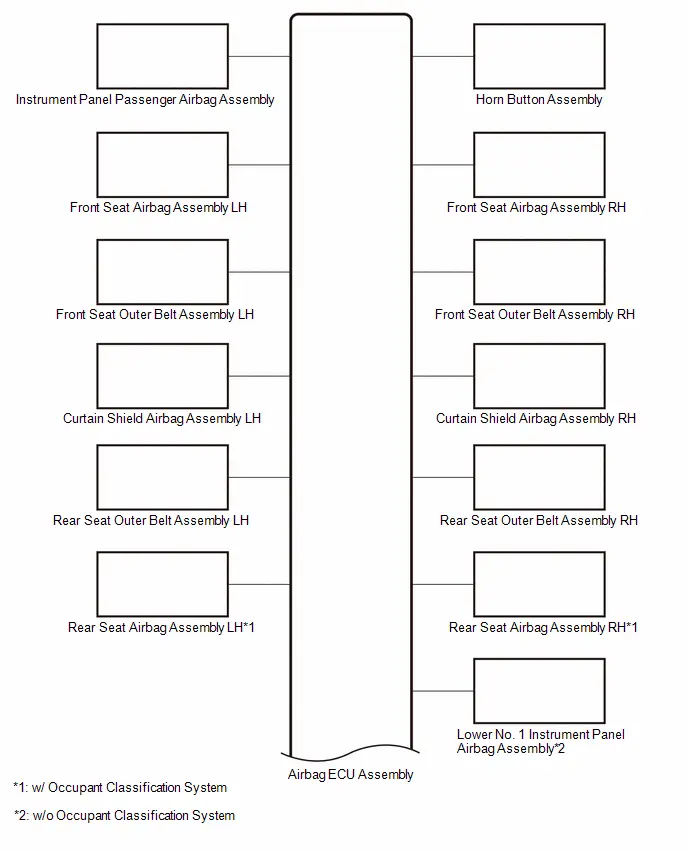
 Communication Table
 | Transmitting ECU / Parts (Transmitter) | Receiving ECU / Parts (Receiver) | Signal | Communication Method |
|---|---|---|---|
|
*1: w/ Manual (SOS) Switch
*2: w/ Occupant Classification System *3: w/o Occupant Classification System | |||
| Front Airbag Sensor | Airbag ECU Assembly | Front collision G signal | Direct line |
| Floor Side Airbag Sensor | Side collision G signal | ||
| Side Airbag Pressure Sensor | Side collision P signal | ||
| Passenger Seat Buckle Switch (Front Seat Inner Belt Assembly RH)*2 | Passenger seat belt fastened signal | ||
| Airbag ECU Assembly | Horn Button Assembly | Ignition signal | Direct line |
| Instrument Panel Passenger Airbag Assembly | |||
| Front Seat Airbag Assembly | |||
| Rear Seat Airbag Assembly*2 | |||
| Lower No. 1 Instrument Panel Airbag Assembly*3 | |||
| Curtain Shield Airbag Assembly | |||
| Front Seat Outer Belt Assembly | |||
| Rear Seat Outer Belt Assembly | |||
| DCM (Telematics Transceiver)*1 | Collision detection signal (for mayday output) | ||
| Main Body ECU (Multiplex Network Body ECU) | Collision detection signal (for door lock release) | ||
| Hybrid Toyota Prius Vehicle Control ECU | Collision detection signal (for hybrid high voltage release) | ||
| Passenger Airbag ON/OFF Indicator (Map Light Assembly)*2 |
| ||
| ECM | Collision detection signal (for fuel cut) | CAN | |
| No. 2 Skid Control ECU (Brake Actuator Assembly) | Collision detection signal (for secondary collision brake) | ||
| DCM (Telematics Transceiver)*1 | VDAS transmission information | ||
| Main Body ECU (Multiplex Network Body ECU) | Interior light illumination request signal | ||
| Hybrid Toyota Prius Vehicle Control ECU | Collision detection signal (for hybrid high voltage release) | ||
| Combination Meter Assembly |
| ||
| Forward Recognition Camera | Airbag ECU Assembly | Front PCS information | |
System Description
SYSTEM DESCRIPTION
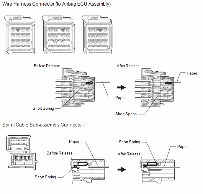
FUNCTION OF SRS CONNECTORS
(a) Location of activation prevention mechanism

| Activation Prevention Mechanism Connector | - | - |
(b) Function of activation prevention mechanism
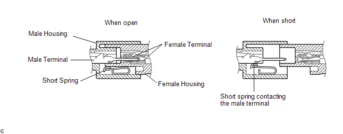
(1) The activation prevention mechanism is designed to create a short circuit automatically between the positive ( ) and negative (-) terminals of an airbag power source connector when disconnected.
(2) The short spring contained in the connector creates a closed circuit on the airbag side (no potential difference can occur between both terminals), preventing accidental airbag deployment when servicing.
(c) Releasing of activation prevention mechanism
(1) To release the activation prevention mechanism, insert a piece of paper with the same thickness as the male terminal (approximately 0.5 mm [0.0197 in.]) between the terminals and short spring to break the connection.
(2) Refer to the following illustrations concerning connectors utilizing the activation prevention mechanism and its release method.
CAUTION:
Never release the activation prevention mechanism on the squib connector even when inspecting with the squib disconnected.
NOTICE:
- Do not release the activation prevention mechanism unless specified by the troubleshooting procedure.
- To prevent the terminals and short spring from being damaged, always use a piece of paper with the same thickness as the male terminal.
HINT:
To prevent improper operation due to static electricity, etc., the connector of the SRS airbag squib circuit has a short mechanism, and the airbag terminal is shorted while the connector is disconnected.

| Short Spring | - | - |
How To Proceed With Troubleshooting
CAUTION / NOTICE / HINT
HINT:
- Use these procedures to troubleshoot the airbag system.
- *: Use the GTS.
PROCEDURE
| 1. | Toyota Prius Vehicle BROUGHT TO WORKSHOP |
|

| 2. | CUSTOMER PROBLEM ANALYSIS |
(a) Confirm problem symptoms.
Click here

|

| 3. | INSPECT AUXILIARY BATTERY VOLTAGE |
(a) Measure the auxiliary battery voltage with the ignition switch off.
Standard Voltage:
11 to 14 V
HINT:
If the voltage is below 11 V, recharge or replace the auxiliary battery before proceeding.
(b) Check the fuses and relays.
(c) Check the connector connections and terminals to make sure that there are no abnormalities such as loose connections, deformation, etc.
|

| 4. | CHECK CAN COMMUNICATION SYSTEM* |
(a) Using the GTS, check if the CAN communication system is functioning normally.
for HEV Model: Click here

for PHEV Model: Click here

HINT:
The airbag ECU assembly is connected to the CAN communication system. Therefore, before starting troubleshooting, make sure to check that there are no malfunctions in the CAN communication system.
| Result | Proceed to |
|---|---|
| DTC is not output | A |
| DTC is output | B |
| B |

| GO TO CAN COMMUNICATION SYSTEM for HEV Model: Click here
for PHEV Model: Click here
|


|

| 5. | CHECK DTC* |
(a) Check for DTCs and freeze frame data.
for Freeze Frame Data: Click here

| Result | Proceed to |
|---|---|
| Airbag system DTCs are output | A |
| Occupant classification system DTCs are output (w/ Occupant Classification System) | B |
| No DTCs are output | C |
| A |

| GO TO DIAGNOSTIC TROUBLE CODE CHART |
| B |

| GO TO DIAGNOSTIC TROUBLE CODE CHART |
|

| 6. | CHECK Toyota Prius Vehicle CONTROL HISTORY (RoB)* |
(a) Check for Vehicle Control History (RoB).
Click here

| Tester Display |
|---|
| Toyota Prius Vehicle Control History (RoB) |
| Result | Proceed to |
|---|---|
| Vehicle Control History (RoB) is not output | A |
| Toyota Prius Vehicle Control History (RoB) is output | B |
| A |

| GO TO PROBLEM SYMPTOMS TABLE |
| B |

| GO TO Toyota Prius Vehicle CONTROL HISTORY (RoB) |
Operation Check
OPERATION CHECK
PRECAUTION FOR OPERATION CHECK
CAUTION:
Use the correct procedure to replace the airbag parts.

CHECK SRS WARNING LIGHT
(a) Primary check
(1) Turn the ignition switch to ON and check that the SRS warning light turns on.
(2) Turn the ignition switch off. Wait for at least 2 seconds, and then turn the ignition switch to ON. The SRS warning light comes on for approximately 6 seconds and diagnosis of the airbag system (including the seat belt pretensioners) is performed.
NOTICE:
Turn the ignition switch off when the auxiliary battery is connected.
HINT:
- If the SRS warning light remains on for approximately 6 seconds or more after the ignition switch has been turned to ON, there may be a malfunction with the airbag system.
- If the warning light occasionally turns on approximately 6 seconds or more after the ignition switch has been turned to ON, there may be a short to B, short to ground or an open in the SRS warning light circuit.
- If the warning light illuminates after turning the ignition switch off or to ACC, there may be a malfunction in the power source circuit or combination meter assembly.
- The SRS warning light turns off, and then turns on. This blinking pattern indicates a source voltage drop. The SRS warning light turns off 6 to 10 seconds after the source voltage returns to normal.
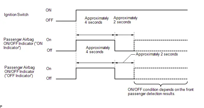
FUNCTION OF PASSENGER AIRBAG ON/OFF INDICATOR (w/ Occupant Classification System)
(a) Initial check
(1) Turn the ignition switch to ON.
(2) The passenger airbag ON/OFF indicator comes on for approximately 4 seconds, and then goes off for approximately 2 seconds.
(3) Approximately 6 seconds after the ignition switch is turned to ON, the passenger airbag ON/OFF indicator will indicate ON/OFF depending on the following conditions.
Indicator Operation| Front Passenger Seat Condition | Passenger Airbag ON/OFF Indicator | SRS Warning Light | |
|---|---|---|---|
| ON Indicator | OFF Indicator | ||
| Vacant | OFF | ON | OFF |
| Adult*1 is seated | ON | OFF | OFF |
| Child*2 is seated | ON or OFF*2 | OFF or ON*2 | OFF |
| Child restraint system is installed | OFF | ON | OFF |
| Occupant classification system failure | OFF | ON | ON |
- *1: The system judges a person of average adult weight or more as an adult. If a smaller adult sits in the front passenger seat, the system may not recognize them as an adult depending on their physique and posture.
- *2: The system may not recognize a child or a child in a child restraint system as a child depending on factors such as the positioning of the child restraint system or the child's physique or posture.
HINT:
- The timing chart below shows the operation of the passenger airbag ON/OFF indicator. Use the chart to check the indicator light circuit.
- When the occupant classification system has trouble, both the SRS warning light and passenger airbag ON/OFF indicator ("OFF") come on. In this case, check for DTCs for "Airbag System" first.
INSPECT AIRBAG COMPONENTS
(a) Inspect the SRS parts in table below.
| Component to Inspect | Procedure |
|---|---|
| Horn button assembly |
|
| Lower No. 1 instrument panel airbag assembly |
|
| Instrument panel passenger airbag assembly |
|
| Curtain shield airbag assembly |
|
| Front seat airbag assembly |
|
| Rear seat airbag assembly |
|
| Front seat outer belt assembly |
|
| Rear seat outer belt assembly |
|
| Airbag ECU assembly |
|
| Front airbag sensor | |
| Side airbag pressure sensor | |
| Floor side airbag sensor | |
| Harness and connector |
Utility
UTILITY
WRITE VIN/VEHICLE IDENTIFICATION NUMBER
NOTICE:
- When the airbag ECU assembly is replaced, it is necessary to write the VIN/Vehicle Identification Number.
-
Since the VIN information of the airbag ECU assembly is acquired via ECM, it is necessary to first write the VIN of ECM.
After writing ECM VIN information, first turn the ignition switch from off to ON and then write VIN information to the airbag ECU assembly.
for M20A-FXS: Click here

for 2ZR-FXE: Click here

(a) Using the GTS, write the VIN/Toyota Prius Vehicle Identification Number.
Body Electrical > SRS Airbag > Utility| Tester Display |
|---|
| VIN Memory |
SWITCHING SPECIFICATION INFORMATION
NOTICE:
- When the airbag ECU assembly is replaced, it is necessary to switch the specification information.
- The airbag ECU assembly specification information is acquired from the forward recognition camera.
(a) Using the GTS, switch the specification information.
Body Electrical > SRS Airbag > Utility| Tester Display |
|---|
| Load Specification Information |
Problem Symptoms Table
PROBLEM SYMPTOMS TABLE
HINT:
Use the table below to help determine the cause of problem symptoms. If multiple suspected areas are listed, the potential causes of the symptoms are listed in order of probability in the "Suspected Area" column of the table. Check each symptom by checking the suspected areas in the order they are listed. Replace parts as necessary.
Airbag System| Symptom | Suspected Area | Link |
|---|---|---|
| SRS warning light goes off after primary check, but then comes on |
|
|
| SRS warning light always comes on even when no DTCs are output |
|
|
| When ignition switch is turned to ON, SRS warning light does not come on |
|
|


Terminals Of Ecu
TERMINALS OF ECU
AIRBAG ECU ASSEMBLY
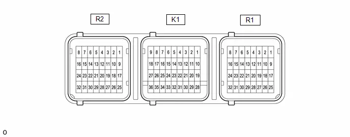
| Terminal No. | Terminal Symbol | Destination |
|---|---|---|
|
*1: w/ Manual (SOS) Switch
*2: w/ Occupant Classification System *3: w/o Occupant Classification System | ||
| R2-3 | PLR- | Rear seat outer belt assembly LH |
| R2-4 | PLR | |
| R2-5 | PL | Front seat outer belt assembly LH |
| R2-6 | PL- | |
| R2-7 | ICL- | Curtain shield airbag assembly LH |
| R2-8 | ICL | |
| R2-13*2 | SRL | Rear seat airbag assembly LH |
| R2-14*2 | SRL- | |
| R2-15 | SFL- | Front seat airbag assembly LH |
| R2-16 | SFL | |
| R2-28 | BBL | Floor side airbag sensor LH |
| R2-29 | BBL- | |
| R2-31 | BDL- | Side airbag pressure sensor LH |
| R2-32 | BDL | |
| K1-1*2 | P2 | Front passenger squib 2nd step (Instrument panel passenger airbag assembly) |
| K1-2*2 | P2- | |
| K1-3 | P- | Front passenger squib (Instrument panel passenger airbag assembly) |
| K1-4 | P | |
| K1-6 | D | Driver squib (Horn button assembly) |
| K1-7 | D- | |
| K1-8*2 | D2- | Driver squib 2nd step (Horn button assembly) |
| K1-9*2 | D2 | |
| K1-12*3 | DK- | Lower No. 1 instrument panel airbag assembly |
| K1-13*3 | DK | |
| K1-23*1 | GSW3 | DCM (Telematics transceiver) |
| K1-24 | GSW2 | Hybrid Toyota Prius vehicle control ECU |
| K1-25 | GSW | Main body ECU (Multiplex network body ECU) |
| K1-26 | CAFH | CAN communication line |
| K1-27 | CAFL | |
| K1-28 | -SR | Front airbag sensor RH |
| K1-29 | SR | |
| K1-30 | SL | Front airbag sensor LH |
| K1-31 | -SL | |
| K1-32 | E2 | Ground |
| K1-33 | E1 | |
| K1-34*2 | P-AB | Passenger airbag ON/OFF indicator (Map light assembly) |
| K1-35*2 | PAON | |
| K1-36 | IGR | A/BAG-IGR fuse |
| R1-1 | ICR | Curtain shield airbag assembly RH |
| R1-2 | ICR- | |
| R1-3 | PR- | Front seat outer belt assembly RH |
| R1-4 | PR | |
| R1-5 | PRR | Rear seat outer belt assembly RH |
| R1-6 | PRR- | |
| R1-9 | SFR | Front seat airbag assembly RH |
| R1-10 | SFR- | |
| R1-11*2 | SRR- | Rear seat airbag assembly RH |
| R1-12*2 | SRR | |
| R1-18*2 | GNDR | Passenger seat buckle switch (Front seat inner belt assembly RH) |
| R1-25 | BDR- | Side airbag pressure sensor RH |
| R1-26 | BDR | |
| R1-27*2 | RBE | Passenger seat buckle switch (Front seat inner belt assembly RH) |
| R1-28 | BBR | Floor side airbag sensor RH |
| R1-29 | BBR- | |
Freeze Frame Data
FREEZE FRAME DATA
DESCRIPTION
(a) When an airbag system DTC is stored, the airbag ECU assembly stores the current vehicle (ECU, sensor or squib) state as Freeze Frame Data.
CHECK FREEZE FRAME DATA
CAUTION:
Never measure the resistance of the SRS parts because current from the tester may cause the SRS parts to deploy.

(a) Check for DTCs.
Body Electrical > SRS Airbag > Trouble Codes(b) According to the GTS display, select a DTC that stored freeze frame data.
(c) Read the freeze frame data recorded when the DTC was stored.
Body Electrical > SRS Airbag| Tester Display | Measurement Item | Range | Normal Condition | Diagnostic Note |
|---|---|---|---|---|
| Total Distance Traveled | - | - | - | Not applicable |
| Total Distance Traveled - Unit | - | - | - | Not applicable |
| IG Voltage | IGR power supply voltage supplied to airbag ECU assembly | 0 to 25.5 V | 12 V | - |
| Voltage After Pressure Rising | Airbag ECU assembly internal voltage | 0 to 51 V | 23.5 V | - |
| Squib Driver Voltage | Airbag ECU assembly internal voltage | 0 to 51 V | 23.5 V | - |
| Satellite Sensor Power Supply Voltage | Airbag ECU assembly internal voltage | 0 to 25.5 V | 9.4 V | - |
| Microcomputer/Sensor Voltage | Airbag ECU assembly internal voltage | 0 to 12.75 V | 3.3 V | - |
| Passenger Seat Buckle Switch Terminal Current (Live) | Current applied to front passenger seat buckle switch (when energized) | 0 to 38.25 mA | LO output (not fastened): 6 mA HI output (fastened): 14.4 mA | w/ Occupant Classification System |
| Passenger Seat Buckle Switch Terminal Voltage (Inactive) | Voltage applied to front passenger seat buckle switch (when not energized) | 0 to 12.75 V | 0.2 V | w/ Occupant Classification System |
| Satellite G Sensor Output Value | Satellite G sensor output value | -100.000 to 99.804 % | 0 % | - |
| Satellite P Sensor Output Value | Satellite pressure sensor output value | 0 to 33.759 % | 0 % | - |
| Satellite P Sensor Absolute Pressure 1 | Absolute pressure output of satellite pressure sensor at initial diagnosis | 35.9223 to 147.5607 kPa(abs) | - | - |
| Satellite P Sensor Absolute Pressure 2 | Absolute pressure output of satellite pressure sensor at initial diagnosis | 35.9223 to 147.5607 kPa(abs) | - | - |
| Driver Seat Airbag Squib Resistance Value | Squib resistance value | 0 to 655.35 OHM | 2.10 to 4.20 OHM | - |
| Driver Seat Airbag Squib Resistance Value Diagnosis Result | Diagnostic result of squib resistance value | Normal or Abnormal | Normal | - |
| Passenger Seat Airbag Squib Resistance Value | Squib resistance value | 0 to 655.35 OHM | 1.80 to 3.00 OHM | - |
| Passenger Seat Airbag Squib Resistance Value Diagnosis Result | Diagnostic result of squib resistance value | Normal or Abnormal | Normal | - |
| Driver Seat 2nd Airbag Squib Resistance Value | Squib resistance value | 0 to 655.35 OHM | 2.10 to 4.20 OHM | w/ Occupant Classification System |
| Driver Seat 2nd Airbag Squib Resistance Value Diagnosis Result | Diagnostic result of squib resistance value | Normal or Abnormal | Normal | w/ Occupant Classification System |
| Passenger Seat 2nd Airbag Squib Resistance Value | Squib resistance value | 0 to 655.35 OHM | 1.80 to 3.00 OHM | w/ Occupant Classification System |
| Passenger Seat 2nd Airbag Squib Resistance Value Diagnosis Result | Diagnostic result of squib resistance value | Normal or Abnormal | Normal | w/ Occupant Classification System |
| Driver Seat Knee Airbag Squib Resistance Value | Squib resistance value | 0 to 655.35 OHM | 2.10 to 4.20 OHM | w/o Occupant Classification System |
| Driver Seat Knee Airbag Squib Resistance Value Diagnosis Result | Diagnostic result of squib resistance value | Normal or Abnormal | Normal | w/o Occupant Classification System |
| Right Side 1st Seat Side-airbag Squib Resistance Value | Squib resistance value | 0 to 655.35 OHM | 1.80 to 3.00 OHM | - |
| Right Side 1st Seat Side-airbag Squib Resistance Value Diagnosis Result | Diagnostic result of squib resistance value | Normal or Abnormal | Normal | - |
| Left Side 1st Seat Side-airbag Squib Resistance Value | Squib resistance value | 0 to 655.35 OHM | 1.80 to 3.00 OHM | - |
| Left Side 1st Seat Side-airbag Squib Resistance Value Diagnosis Result | Diagnostic result of squib resistance value | Normal or Abnormal | Normal | - |
| Driver Seat Pretensioner Squib Resistance Value | Squib resistance value | 0 to 655.35 OHM | 2.10 to 4.20 OHM | - |
| Driver Seat Pretensioner Squib Resistance Value Diagnosis Result | Diagnostic result of squib resistance value | Normal or Abnormal | Normal | - |
| Passenger Seat Pretensioner Squib Resistance Value | Squib resistance value | 0 to 655.35 OHM | 1.80 to 3.00 OHM | - |
| Passenger Seat Pretensioner Squib Resistance Value Diagnosis Result | Diagnostic result of squib resistance value | Normal or Abnormal | Normal | - |
| Right Side Curtain Shield Airbag Squib Resistance Value | Squib resistance value | 0 to 655.35 OHM | 1.80 to 3.00 OHM | - |
| Right Side Curtain Shield Airbag Squib Resistance Value Diagnosis Result | Diagnostic result of squib resistance value | Normal or Abnormal | Normal | - |
| Left Side Curtain Shield Airbag Squib Resistance Value | Squib resistance value | 0 to 655.35 OHM | 1.80 to 3.00 OHM | - |
| Left Side Curtain Shield Airbag Squib Resistance Value Diagnosis Result | Diagnostic result of squib resistance value | Normal or Abnormal | Normal | - |
| Right Side 2nd Seat Side-airbag Squib Resistance Value | Squib resistance value | 0 to 655.35 OHM | 1.80 to 3.00 OHM | w/ Occupant Classification System |
| Right Side 2nd Seat Side-airbag Squib Resistance Value Diagnosis Result | Diagnostic result of squib resistance value | Normal or Abnormal | Normal | w/ Occupant Classification System |
| Left Side 2nd Seat Side-airbag Squib Resistance Value | Squib resistance value | 0 to 655.35 OHM | 1.80 to 3.00 OHM | w/ Occupant Classification System |
| Left Side 2nd Seat Side-airbag Squib Resistance Value Diagnosis Result | Diagnostic result of squib resistance value | Normal or Abnormal | Normal | w/ Occupant Classification System |
| Right Side 2nd Seat Pretensioner Squib Resistance Value | Squib resistance value | 0 to 655.35 OHM | 1.80 to 3.00 OHM | - |
| Right Side 2nd Seat Pretensioner Squib Resistance Value Diagnosis Result | Diagnostic result of squib resistance value | Normal or Abnormal | Normal | - |
| Left Side 2nd Seat Pretensioner Squib Resistance Value | Squib resistance value | 0 to 655.35 OHM | 1.80 to 3.00 OHM | - |
| Left Side 2nd Seat Pretensioner Squib Resistance Value Diagnosis Result | Diagnostic result of squib resistance value | Normal or Abnormal | Normal | - |
Check Mode Procedure
CHECK MODE PROCEDURE
CHECK MODE: DTC CHECK
(a) Select "Check Mode" and proceed with checking using the GTS.
Body Electrical > SRS Airbag > Utility| Tester Display |
|---|
| Check Mode |
NOTICE:
Select Check Mode on the GTS to clear the DTCs.
HINT:
- DTCs can be detected more sensitively in check mode than in normal diagnosis mode.
- Perform check mode inspection when a malfunction in a squib circuit is suspected even after the normal system code is output through normal diagnosis mode inspection.
Data List / Active Test
DATA LIST / ACTIVE TEST
DATA LIST
CAUTION:
Never measure the resistance of the SRS parts because current from the tester may cause the SRS parts to deploy.
NOTICE:
In the table below, the values listed under "Normal Condition" are reference values. Do not depend solely on these reference values when deciding whether a part is faulty or not.
HINT:
Using the GTS to read the Data List allows the values or states of switches, sensors, actuators and other items to be read without removing any parts. This non-intrusive inspection can be very useful because intermittent conditions or signals may be discovered before parts or wiring is disturbed. Reading the Data List information early in troubleshooting is one way to save diagnostic time.
(a) Read the Data List according to the display on the GTS.
Body Electrical > SRS Airbag > Data List| Tester Display | Measurement Item | Range | Normal Condition | Diagnostic Note |
|---|---|---|---|---|
| Total Distance Traveled | - | - | - | Not applicable |
| Total Distance Traveled - Unit | - | - | - | Not applicable |
| Occupant Detection Status | Front passenger classification | Unknown, Nothing, Child, Female, Male or Malfunction | Nothing, Child, Female or Male | w/ Occupant Classification System |
| Passenger Seat Buckle Switch Status | Front passenger seat belt fastening status | Unknown, Unbuckle, Buckle or Malfunction | Unbuckle or Buckle | w/ Occupant Classification System |
| Driver Seat Airbag Squib Resistance Value | Squib resistance value | 0 to 655.35 OHM | 2.10 to 4.20 OHM | - |
| Driver Seat Airbag Squib Resistance Value Diagnosis Result | Diagnostic result of squib resistance value | Normal or Abnormal | Normal | - |
| Passenger Seat Airbag Squib Resistance Value | Squib resistance value | 0 to 655.35 OHM | 1.80 to 3.00 OHM | - |
| Passenger Seat Airbag Squib Resistance Value Diagnosis Result | Diagnostic result of squib resistance value | Normal or Abnormal | Normal | - |
| Driver Seat 2nd Airbag Squib Resistance Value | Squib resistance value | 0 to 655.35 OHM | 2.10 to 4.20 OHM | w/ Occupant Classification System |
| Driver Seat 2nd Airbag Squib Resistance Value Diagnosis Result | Diagnostic result of squib resistance value | Normal or Abnormal | Normal | w/ Occupant Classification System |
| Passenger Seat 2nd Airbag Squib Resistance Value | Squib resistance value | 0 to 655.35 OHM | 1.80 to 3.00 OHM | w/ Occupant Classification System |
| Passenger Seat 2nd Airbag Squib Resistance Value Diagnosis Result | Diagnostic result of squib resistance value | Normal or Abnormal | Normal | w/ Occupant Classification System |
| Driver Seat Knee Airbag Squib Resistance Value | Squib resistance value | 0 to 655.35 OHM | 2.10 to 4.20 OHM | w/o Occupant Classification System |
| Driver Seat Knee Airbag Squib Resistance Value Diagnosis Result | Diagnostic result of squib resistance value | Normal or Abnormal | Normal | w/o Occupant Classification System |
| Right Side 1st Seat Side-airbag Squib Resistance Value | Squib resistance value | 0 to 655.35 OHM | 1.80 to 3.00 OHM | - |
| Right Side 1st Seat Side-airbag Squib Resistance Value Diagnosis Result | Diagnostic result of squib resistance value | Normal or Abnormal | Normal | - |
| Left Side 1st Seat Side-airbag Squib Resistance Value | Squib resistance value | 0 to 655.35 OHM | 1.80 to 3.00 OHM | - |
| Left Side 1st Seat Side-airbag Squib Resistance Value Diagnosis Result | Diagnostic result of squib resistance value | Normal or Abnormal | Normal | - |
| Driver Seat Pretensioner Squib Resistance Value | Squib resistance value | 0 to 655.35 OHM | 2.10 to 4.20 OHM | - |
| Driver Seat Pretensioner Squib Resistance Value Diagnosis Result | Diagnostic result of squib resistance value | Normal or Abnormal | Normal | - |
| Passenger Seat Pretensioner Squib Resistance Value | Squib resistance value | 0 to 655.35 OHM | 1.80 to 3.00 OHM | - |
| Passenger Seat Pretensioner Squib Resistance Value Diagnosis Result | Diagnostic result of squib resistance value | Normal or Abnormal | Normal | - |
| Right Side Curtain Shield Airbag Squib Resistance Value | Squib resistance value | 0 to 655.35 OHM | 1.80 to 3.00 OHM | - |
| Right Side Curtain Shield Airbag Squib Resistance Value Diagnosis Result | Diagnostic result of squib resistance value | Normal or Abnormal | Normal | - |
| Left Side Curtain Shield Airbag Squib Resistance Value | Squib resistance value | 0 to 655.35 OHM | 1.80 to 3.00 OHM | - |
| Left Side Curtain Shield Airbag Squib Resistance Value Diagnosis Result | Diagnostic result of squib resistance value | Normal or Abnormal | Normal | - |
| Right Side 2nd Seat Side-airbag Squib Resistance Value | Squib resistance value | 0 to 655.35 OHM | 1.80 to 3.00 OHM | w/ Occupant Classification System |
| Right Side 2nd Seat Side-airbag Squib Resistance Value Diagnosis Result | Diagnostic result of squib resistance value | Normal or Abnormal | Normal | w/ Occupant Classification System |
| Left Side 2nd Seat Side-airbag Squib Resistance Value | Squib resistance value | 0 to 655.35 OHM | 1.80 to 3.00 OHM | w/ Occupant Classification System |
| Left Side 2nd Seat Side-airbag Squib Resistance Value Diagnosis Result | Diagnostic result of squib resistance value | Normal or Abnormal | Normal | w/ Occupant Classification System |
| Right Side 2nd Seat Pretensioner Squib Resistance Value | Squib resistance value | 0 to 655.35 OHM | 1.80 to 3.00 OHM | - |
| Right Side 2nd Seat Pretensioner Squib Resistance Value Diagnosis Result | Diagnostic result of squib resistance value | Normal or Abnormal | Normal | - |
| Left Side 2nd Seat Pretensioner Squib Resistance Value | Squib resistance value | 0 to 655.35 OHM | 1.80 to 3.00 OHM | - |
| Left Side 2nd Seat Pretensioner Squib Resistance Value Diagnosis Result | Diagnostic result of squib resistance value | Normal or Abnormal | Normal | - |
How To Connect Or Disconnect Airbag Connector
HOW TO CONNECT OR DISCONNECT AIRBAG CONNECTOR
PROCEDURE
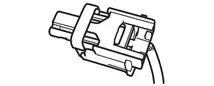
1. TYPES OF AIRBAG CONNECTOR
(a) Types of Connector
| TYPE | Shape (Example) |
|---|---|
| Pull Up Type |

|
| 2-Step Lock Type |
|
| Slide Lock Type |


|
2. DISCONNECT OR CONNECT AIRBAG CONNECTOR (for Pull Up Type)
(a) Disconnect the connector.
(1) Using a screwdriver with its tip wrapped with protective tape, release the connector locking button.
(2) Disconnect the airbag connector.
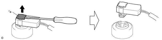
| *a | Connector Locking Button | - | - |
(b) Connect the connector.
(1) Connect the airbag connector.
(2) Push in the connector locking button to install the connector.
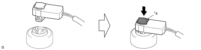
| *a | Connector Locking Button | - | - |
3. DISCONNECT OR CONNECT AIRBAG CONNECTOR (for 2-Step Lock Type)
(a) Disconnect the connector.
(1) Push down the release button and slide the sides of the connector in the direction shown by the arrows in the illustration. (At this time, the connector cannot be disconnected yet.)
NOTICE:
- Do not pull the wire harness.
- Pushing down on the top of the connector will prevent the lock from being released, so hold the sides of the connector.
(2) Check that the position of the release button is as shown in the illustration.
(3) Push down the release button and slide the connector again to disconnect the airbag connector.
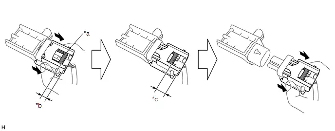
| *a | Release Button | *b | Position when Locked |
| *c | Position when Released | - | - |
(b) Connect the connector.
(1) Before connecting the connector, check that the position of the release button is as shown in the illustration.
(2) While holding the sides of the connector, slide the connector in the direction shown by the arrow in the illustration until a click sound is heard to connect the airbag connector, and check that the release button is in its original position.
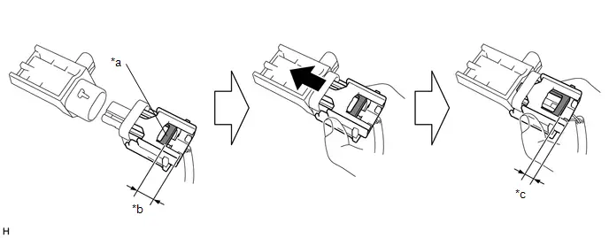
| *a | Release Button | *b | Position when Released |
| *c | Position when Locked | - | - |
NOTICE:
- Slide the connector in straight to connect it. Be careful not to pry the connector.
- To prevent deformation of the connector and possible damage to the partial engagement prevention mechanism, do not press down on the top surface of the connector when connecting it. Be sure to hold the connector by the sides.
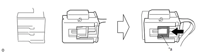
4. DISCONNECT OR CONNECT AIRBAG CONNECTOR (for Slide Lock Type)
(a) Disconnect the connector.
(1) Slide the slider in the direction shown by the arrow to release the lock.
(2) Disconnect the airbag connector.

| *a | Slider | - | - |
(b) Connect the connector.
(1) Connect the airbag connector.
HINT:
If the slider is not in the lock position, the connector is not completely connected. Disconnect the connector, check the connector, spiral cable with sensor sub-assembly terminals and connector housings for deformation or foreign matter, and then reconnect the connector.
(2) Slide the slider in the direction shown by the arrow to lock it, and check that the slider is in the lock position.
| *a | Slider | - | - |
Diagnostic Trouble Code Chart
DIAGNOSTIC TROUBLE CODE CHART
Airbag System| DTC No. | Detection Item | Warning Indicate | DTC Output from | Priority | Test Mode / Check Mode | Link |
|---|---|---|---|---|---|---|
| B000111 | Driver Frontal Stage 1 Deployment Control Circuit Short to Ground | Comes on | SRS Airbag | A | Applies to check mode |
|
| B000112 | Driver Frontal Stage 1 Deployment Control Circuit Short to Battery | Comes on | SRS Airbag | A | Applies to check mode |
|
| B000113 | Driver Frontal Stage 1 Deployment Control Circuit Open | Comes on | SRS Airbag | A | Applies to check mode |
|
| B00011A | Driver Frontal Stage 1 Deployment Control Circuit Resistance Below Threshold | Comes on | SRS Airbag | A | Applies to check mode |
|
| B000211 | Driver Frontal Stage 2 Deployment Control Circuit Short to Ground | Comes on | SRS Airbag | A | Applies to check mode |
|
| B000212 | Driver Frontal Stage 2 Deployment Control Circuit Short to Battery | Comes on | SRS Airbag | A | Applies to check mode |
|
| B000213 | Driver Frontal Stage 2 Deployment Control Circuit Open | Comes on | SRS Airbag | A | Applies to check mode |
|
| B00021A | Driver Frontal Stage 2 Deployment Control Circuit Resistance Below Threshold | Comes on | SRS Airbag | A | Applies to check mode |
|
| B000411 | Driver Knee Bolster Deployment Control Circuit Short to Ground | Comes on | SRS Airbag | A | Applies to check mode |
|
| B000412 | Driver Knee Bolster Deployment Control Circuit Short to Battery | Comes on | SRS Airbag | A | Applies to check mode |
|
| B000413 | Driver Knee Bolster Deployment Control Circuit Open | Comes on | SRS Airbag | A | Applies to check mode |
|
| B00041A | Driver Knee Bolster Deployment Control Circuit Resistance Below Threshold | Comes on | SRS Airbag | A | Applies to check mode |
|
| B001011 | Passenger Frontal Stage 1 Deployment Control Circuit Short to Ground | Comes on | SRS Airbag | A | Applies to check mode |
|
| B001012 | Passenger Frontal Stage 1 Deployment Control Circuit Short to Battery | Comes on | SRS Airbag | A | Applies to check mode |
|
| B001013 | Passenger Frontal Stage 1 Deployment Control Circuit Open | Comes on | SRS Airbag | A | Applies to check mode |
|
| B00101A | Passenger Frontal Stage 1 Deployment Control Circuit Resistance Below Threshold | Comes on | SRS Airbag | A | Applies to check mode |
|
| B001111 | Passenger Frontal Stage 2 Deployment Control Circuit Short to Ground | Comes on | SRS Airbag | A | Applies to check mode |
|
| B001112 | Passenger Frontal Stage 2 Deployment Control Circuit Short to Battery | Comes on | SRS Airbag | A | Applies to check mode |
|
| B001113 | Passenger Frontal Stage 2 Deployment Control Circuit Open | Comes on | SRS Airbag | A | Applies to check mode |
|
| B00111A | Passenger Frontal Stage 2 Deployment Control Circuit Resistance Below Threshold | Comes on | SRS Airbag | A | Applies to check mode |
|
| B002011 | Left Side Airbag Deployment Control Circuit Short to Ground | Comes on | SRS Airbag | A | Applies to check mode |
|
| B002012 | Left Side Airbag Deployment Control Circuit Short to Battery | Comes on | SRS Airbag | A | Applies to check mode |
|
| B002013 | Left Side Airbag Deployment Control Circuit Open | Comes on | SRS Airbag | A | Applies to check mode |
|
| B00201A | Left Side Airbag Deployment Control Circuit Resistance Below Threshold | Comes on | SRS Airbag | A | Applies to check mode |
|
| B002111 | Left Curtain Deployment Control 1 Circuit Short to Ground | Comes on | SRS Airbag | A | Applies to check mode |
|
| B002112 | Left Curtain Deployment Control 1 Circuit Short to Battery | Comes on | SRS Airbag | A | Applies to check mode |
|
| B002113 | Left Curtain Deployment Control 1 Circuit Open | Comes on | SRS Airbag | A | Applies to check mode |
|
| B00211A | Left Curtain Deployment Control 1 Circuit Resistance Below Threshold | Comes on | SRS Airbag | A | Applies to check mode |
|
| B002811 | Right Side Airbag Deployment Control Circuit Short to Ground | Comes on | SRS Airbag | A | Applies to check mode |
|
| B002812 | Right Side Airbag Deployment Control Circuit Short to Battery | Comes on | SRS Airbag | A | Applies to check mode |
|
| B002813 | Right Side Airbag Deployment Control Circuit Open | Comes on | SRS Airbag | A | Applies to check mode |
|
| B00281A | Right Side Airbag Deployment Control Circuit Resistance Below Threshold | Comes on | SRS Airbag | A | Applies to check mode |
|
| B002911 | Right Curtain Deployment Control 1 Circuit Short to Ground | Comes on | SRS Airbag | A | Applies to check mode |
|
| B002912 | Right Curtain Deployment Control 1 Circuit Short to Battery | Comes on | SRS Airbag | A | Applies to check mode |
|
| B002913 | Right Curtain Deployment Control 1 Circuit Open | Comes on | SRS Airbag | A | Applies to check mode |
|
| B00291A | Right Curtain Deployment Control 1 Circuit Resistance Below Threshold | Comes on | SRS Airbag | A | Applies to check mode |
|
| B003011 | Second Row Left Side Airbag Deployment Control Circuit Short to Ground | Comes on | SRS Airbag | A | Applies to check mode |
|
| B003012 | Second Row Left Side Airbag Deployment Control Circuit Short to Battery | Comes on | SRS Airbag | A | Applies to check mode |
|
| B003013 | Second Row Left Side Airbag Deployment Control Circuit Open | Comes on | SRS Airbag | A | Applies to check mode |
|
| B00301A | Second Row Left Side Airbag Deployment Control Circuit Resistance Below Threshold | Comes on | SRS Airbag | A | Applies to check mode |
|
| B003811 | Second Row Right Side Airbag Deployment Control Circuit Short to Ground | Comes on | SRS Airbag | A | Applies to check mode |
|
| B003812 | Second Row Right Side Airbag Deployment Control Circuit Short to Battery | Comes on | SRS Airbag | A | Applies to check mode |
|
| B003813 | Second Row Right Side Airbag Deployment Control Circuit Open | Comes on | SRS Airbag | A | Applies to check mode |
|
| B00381A | Second Row Right Side Airbag Deployment Control Circuit Resistance Below Threshold | Comes on | SRS Airbag | A | Applies to check mode |
|
| B005200 | Passenger Seat Belt Sensor Circuit Undetermined Failure | Comes on | SRS Airbag | A | Does not apply to test/check mode |
|
| B005211 | Passenger Seat Belt Sensor Circuit Short to Ground | Comes on | SRS Airbag | A | Does not apply to test/check mode |
|
| B005212 | Passenger Seat Belt Sensor Circuit Short to Battery | Comes on | SRS Airbag | A | Does not apply to test/check mode |
|
| B005213 | Passenger Seat Belt Sensor Circuit Open | Comes on | SRS Airbag | A | Does not apply to test/check mode |
|
| B007011 | Driver Seat Belt Pretensioner "A" Deployment Control Circuit Short to Ground | Comes on | SRS Airbag | A | Applies to check mode |
|
| B007012 | Driver Seat Belt Pretensioner "A" Deployment Control Circuit Short to Battery | Comes on | SRS Airbag | A | Applies to check mode |
|
| B007013 | Driver Seat Belt Pretensioner "A" Deployment Control Circuit Open | Comes on | SRS Airbag | A | Applies to check mode |
|
| B00701A | Driver Seat Belt Pretensioner "A" Deployment Control Circuit Resistance Below Threshold | Comes on | SRS Airbag | A | Applies to check mode |
|
| B007211 | Passenger Seat Belt Pretensioner "A" Deployment Control Circuit Short to Ground | Comes on | SRS Airbag | A | Applies to check mode |
|
| B007212 | Passenger Seat Belt Pretensioner "A" Deployment Control Circuit Short to Battery | Comes on | SRS Airbag | A | Applies to check mode |
|
| B007213 | Passenger Seat Belt Pretensioner "A" Deployment Control Circuit Open | Comes on | SRS Airbag | A | Applies to check mode |
|
| B00721A | Passenger Seat Belt Pretensioner "A" Deployment Control Circuit Resistance Below Threshold | Comes on | SRS Airbag | A | Applies to check mode |
|
| B007311 | Second Row Left Seat Belt Pretensioner Deployment Control Circuit Short to Ground | Comes on | SRS Airbag | A | Applies to check mode |
|
| B007312 | Second Row Left Seat Belt Pretensioner Deployment Control Circuit Short to Battery | Comes on | SRS Airbag | A | Applies to check mode |
|
| B007313 | Second Row Left Seat Belt Pretensioner Deployment Control Circuit Open | Comes on | SRS Airbag | A | Applies to check mode |
|
| B00731A | Second Row Left Seat Belt Pretensioner Deployment Control Circuit Resistance Below Threshold | Comes on | SRS Airbag | A | Applies to check mode |
|
| B007511 | Second Row Right Seat Belt Pretensioner Deployment Control Circuit Short to Ground | Comes on | SRS Airbag | A | Applies to check mode |
|
| B007512 | Second Row Right Seat Belt Pretensioner Deployment Control Circuit Short to Battery | Comes on | SRS Airbag | A | Applies to check mode |
|
| B007513 | Second Row Right Seat Belt Pretensioner Deployment Control Circuit Open | Comes on | SRS Airbag | A | Applies to check mode |
|
| B00751A | Second Row Right Seat Belt Pretensioner Deployment Control Circuit Resistance Below Threshold | Comes on | SRS Airbag | A | Applies to check mode |
|
| B009083 | Left Frontal Restraints Sensor Value of Signal Protection Calculation Incorrect | Comes on | SRS Airbag | A | Does not apply to test/check mode |
|
| B009084 | Left Frontal Restraints Sensor Signal Below Allowable Range | Comes on | SRS Airbag | A | Does not apply to test/check mode |
|
| B009085 | Left Frontal Restraints Sensor Signal Above Allowable Range | Comes on | SRS Airbag | A | Does not apply to test/check mode |
|
| B009087 | Left Frontal Restraints Sensor Missing Message | Comes on | SRS Airbag | A | Does not apply to test/check mode |
|
| B009096 | Left Frontal Restraints Sensor Component Internal Failure | Comes on | SRS Airbag | A | Does not apply to test/check mode |
|
| B009283 | Left Side Restraints Sensor 2 Value of Signal Protection Calculation Incorrect | Comes on | SRS Airbag | A | Does not apply to test/check mode |
|
| B009284 | Left Side Restraints Sensor 2 Signal Below Allowable Range | Comes on | SRS Airbag | A | Does not apply to test/check mode |
|
| B009285 | Left Side Restraints Sensor 2 Signal Above Allowable Range | Comes on | SRS Airbag | A | Does not apply to test/check mode |
|
| B009287 | Left Side Restraints Sensor 2 Missing Message | Comes on | SRS Airbag | A | Does not apply to test/check mode |
|
| B009296 | Left Side Restraints Sensor 2 Component Internal Failure | Comes on | SRS Airbag | A | Does not apply to test/check mode |
|
| B009583 | Right Frontal Restraints Sensor Value of Signal Protection Calculation Incorrect | Comes on | SRS Airbag | A | Does not apply to test/check mode |
|
| B009584 | Right Frontal Restraints Sensor Signal Below Allowable Range | Comes on | SRS Airbag | A | Does not apply to test/check mode |
|
| B009585 | Right Frontal Restraints Sensor Signal Above Allowable Range | Comes on | SRS Airbag | A | Does not apply to test/check mode |
|
| B009587 | Right Frontal Restraints Sensor Missing Message | Comes on | SRS Airbag | A | Does not apply to test/check mode |
|
| B009596 | Right Frontal Restraints Sensor Component Internal Failure | Comes on | SRS Airbag | A | Does not apply to test/check mode |
|
| B009783 | Right Side Restraints Sensor 2 Value of Signal Protection Calculation Incorrect | Comes on | SRS Airbag | A | Does not apply to test/check mode |
|
| B009784 | Right Side Restraints Sensor 2 Signal Below Allowable Range | Comes on | SRS Airbag | A | Does not apply to test/check mode |
|
| B009785 | Right Side Restraints Sensor 2 Signal Above Allowable Range | Comes on | SRS Airbag | A | Does not apply to test/check mode |
|
| B009787 | Right Side Restraints Sensor 2 Missing Message | Comes on | SRS Airbag | A | Does not apply to test/check mode |
|
| B009796 | Right Side Restraints Sensor 2 Component Internal Failure | Comes on | SRS Airbag | A | Does not apply to test/check mode |
|
| B009B64 | Left Side Restraints Sensor 5 Signal Plausibility Failure | Comes on | SRS Airbag | A | Does not apply to test/check mode |
|
| B009B83 | Left Side Restraints Sensor 5 Value of Signal Protection Calculation Incorrect | Comes on | SRS Airbag | A | Does not apply to test/check mode |
|
| B009B84 | Left Side Restraints Sensor 5 Signal Below Allowable Range | Comes on | SRS Airbag | A | Does not apply to test/check mode |
|
| B009B85 | Left Side Restraints Sensor 5 Signal Above Allowable Range | Comes on | SRS Airbag | A | Does not apply to test/check mode |
|
| B009B87 | Left Side Restraints Sensor 5 Missing Message | Comes on | SRS Airbag | A | Does not apply to test/check mode |
|
| B009B96 | Left Side Restraints Sensor 5 Component Internal Failure | Comes on | SRS Airbag | A | Does not apply to test/check mode |
|
| B009E64 | Right Side Restraints Sensor 5 Signal Plausibility Failure | Comes on | SRS Airbag | A | Does not apply to test/check mode |
|
| B009E83 | Right Side Restraints Sensor 5 Value of Signal Protection Calculation Incorrect | Comes on | SRS Airbag | A | Does not apply to test/check mode |
|
| B009E84 | Right Side Restraints Sensor 5 Signal Below Allowable Range | Comes on | SRS Airbag | A | Does not apply to test/check mode |
|
| B009E85 | Right Side Restraints Sensor 5 Signal Above Allowable Range | Comes on | SRS Airbag | A | Does not apply to test/check mode |
|
| B009E87 | Right Side Restraints Sensor 5 Missing Message | Comes on | SRS Airbag | A | Does not apply to test/check mode |
|
| B009E96 | Right Side Restraints Sensor 5 Component Internal Failure | Comes on | SRS Airbag | A | Does not apply to test/check mode |
|
| B00D212 | Restraint System Malfunction Indicator 1 Circuit Short to Battery | Comes on | SRS Airbag | A | Does not apply to test/check mode |
|
| B00D214 | Restraint System Malfunction Indicator 1 Circuit Short to Ground or Open | Comes on | SRS Airbag | A | Does not apply to test/check mode |
|
| B00D512 | Restraint System Passenger Disable Indicator Circuit Short to Battery | Comes on | SRS Airbag | A | Does not apply to test/check mode |
|
| B00D514 | Restraint System Passenger Disable Indicator Circuit Short to Ground or Open | Comes on | SRS Airbag | A | Does not apply to test/check mode |
|
| B116049 | Airbag ECU (Microcomputer) Internal Electronic Failure | Comes on | SRS Airbag | A | Does not apply to test/check mode |
|
| B11609E | Airbag ECU (Microcomputer) Stuck On | Comes on | SRS Airbag | A | Does not apply to test/check mode |
|
| B116149 | Airbag ECU (Main ASIC) Internal Electronic Failure | Comes on | SRS Airbag | A | Does not apply to test/check mode |
|
| B11619E | Airbag ECU (Main ASIC) Stuck On | Comes on | SRS Airbag | A | Does not apply to test/check mode |
|
| B116311 | Airbag ECU (IC and Device) Circuit Short to Ground | Comes on | SRS Airbag | A | Does not apply to test/check mode |
|
| B116349 | Airbag ECU (IC and Device) Internal Electronic Failure | Comes on | SRS Airbag | A | Does not apply to test/check mode |
|
| B11639E | Airbag ECU (IC and Device) Stuck On | Comes on | SRS Airbag | A | Does not apply to test/check mode |
|
| B11639F | Airbag ECU (IC and Device) Stuck Off | Comes on | SRS Airbag | A | Does not apply to test/check mode |
|
| B116449 | Airbag ECU (G Sensor 1) Internal Electronic Failure | Comes on | SRS Airbag | A | Does not apply to test/check mode |
|
| B116483 | Airbag ECU (G Sensor 1) Value of Signal Protection Calculation Incorrect | Comes on | SRS Airbag | A | Does not apply to test/check mode |
|
| B116484 | Airbag ECU (G Sensor 1) Signal Below Allowable Range | Comes on | SRS Airbag | A | Does not apply to test/check mode |
|
| B116485 | Airbag ECU (G Sensor 1) Signal Above Allowable Range | Comes on | SRS Airbag | A | Does not apply to test/check mode |
|
| B116549 | Airbag ECU (G Sensor 2) Internal Electronic Failure | Comes on | SRS Airbag | A | Does not apply to test/check mode |
|
| B116583 | Airbag ECU (G Sensor 2) Value of Signal Protection Calculation Incorrect | Comes on | SRS Airbag | A | Does not apply to test/check mode |
|
| B116584 | Airbag ECU (G Sensor 2) Signal Below Allowable Range | Comes on | SRS Airbag | A | Does not apply to test/check mode |
|
| B116585 | Airbag ECU (G Sensor 2) Signal Above Allowable Range | Comes on | SRS Airbag | A | Does not apply to test/check mode |
|
| B116649 | Airbag ECU (G Sensor 3) Internal Electronic Failure | Comes on | SRS Airbag | A | Does not apply to test/check mode |
|
| B116683 | Airbag ECU (G Sensor 3) Value of Signal Protection Calculation Incorrect | Comes on | SRS Airbag | A | Does not apply to test/check mode |
|
| B116684 | Airbag ECU (G Sensor 3) Signal Below Allowable Range | Comes on | SRS Airbag | A | Does not apply to test/check mode |
|
| B116685 | Airbag ECU (G Sensor 3) Signal Above Allowable Range | Comes on | SRS Airbag | A | Does not apply to test/check mode |
|
| B116749 | Airbag ECU (Roll Sensor) Internal Electronic Failure | Comes on | SRS Airbag | A | Does not apply to test/check mode |
|
| B116783 | Airbag ECU (Roll Sensor) Value of Signal Protection Calculation Incorrect | Comes on | SRS Airbag | A | Does not apply to test/check mode |
|
| B116784 | Airbag ECU (Roll Sensor) Signal Below Allowable Range | Comes on | SRS Airbag | A | Does not apply to test/check mode |
|
| B116785 | Airbag ECU (Roll Sensor) Signal Above Allowable Range | Comes on | SRS Airbag | A | Does not apply to test/check mode |
|
| B116800 | Airbag ECU Failure (Write Inhibit of EDR) | Comes on | SRS Airbag | A | Does not apply to test/check mode |
|
| B166A62 | Right Side Restraints Sensor 5 / Left Side Restraints Sensor 5 Signal Compare Failure | Comes on | SRS Airbag | A | Does not apply to test/check mode |
|
| P05BB00 | Restraints Deployed | Comes on | SRS Airbag | A | Does not apply to test/check mode |
|
| U012987 | Lost Communication with Brake System Control Module "A" Missing Message | Comes on | SRS Airbag | B | Does not apply to test/check mode |
|
| U023A87 | Lost Communication with Image Processing Module "A" Missing Message | Comes on | SRS Airbag | B | Does not apply to test/check mode |
|


Vehicle Control History
VEHICLE CONTROL HISTORY
FUNCTION OVERVIEW
(a) The vehicle control history is a function that records control data (record data) when triggered by specific vehicle behavior or user input. Checking the vehicle control history may provide, quantitative diagnostic information that can be used as a reference to proceed with a malfunction diagnosis. However, due to limitations of the data recorded, such as the resolution, data range, sampling interval, time period of the recording, and the items recorded, the information provided by this data may not be sufficient to capture the entire event. Data storage properties may also affect the way data is output.
(b) The Toyota Prius vehicle control history may also stores image data when a specific trigger is set.
(c) The vehicle control history is recorded in different storage areas designated by trigger group and it is possible to save up to 140 items in total. Newer events with Vehicle Control History "VCH"/ Freeze Frame Data "FFD" may overwrite data from past events.
(d) Each trigger receives time information from the central gateway ECU (time elapsed since ignition switch turned to ON), the telematics system or navigation system* (absolute time).
- *: Only for factory-installed navigation systems (factory option)
(e) Data is recorded in the airbag ECU assembly EEPROM. Even if the negative (-) auxiliary battery terminal is disconnected, the Toyota Prius vehicle control history is available.
(f) The image data is stored in the camera sensor EEPROM.
NOTICES FOR USE
(a) Vehicle control history is used as support information during diagnosis for each system.
(b) Trigger data is based on signals from sensors and actuators (recognition value of each ECU).
Basic Flow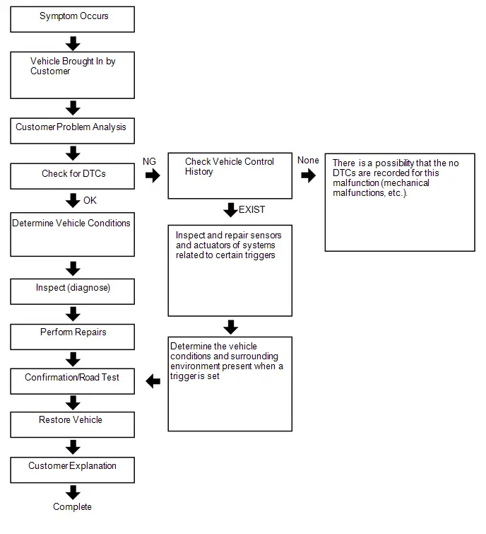
TRIGGER ITEM
(a) Turn the ignition switch to ON
NOTICE:
The automatic power off function operates after 20 minutes with the ignition switch ON. If reading will take some time to complete, engine start or turn the ignition switch on (READY) first.
Body Electrical > SRS Airbag > Utility| Tester Display |
|---|
| Toyota Prius Vehicle Control History |
| Related System | Storage Area Group (storage limit) | Trigger Item Name | Trigger Description | Image Recording | Remarks |
|---|---|---|---|---|---|
| Engine Control / Hybrid Control / Automatic Transmission | Area 17 (Approximately 3 times) | Step on accelerator pedal quickly in low to mid speed and accelerator pedal opening angle high | Sudden accelerator depression and an accelerator high position signal are detected while in the low to mid speed range. | - | - |
| Area 2 (Approximately 11 times) | Accelerator pedal opening angle signal is high during low speed | An accelerator high position signal condition continues for a certain period of time while in the low speed range. | - | - | |
| Accelerator pedal opening angle signal is high immediately after brake pedal is released | An accelerator high position signal is received while in the low speed range after there is a change from brake input condition to brake and accelerator pedal released condition. | - | - | ||
| Area 7 (Approximately 7 times) | Accelerator high position in mid to high speed | An accelerator high position signal condition continues for a certain period of time while in the mid to high speed range. | - | - | |
| Engine Control / Hybrid Control / Automatic Transmission | Area 3 (Approximately 21 times) | Accelerator pedal opening angle is medium or higher immediately after shifting to R | An accelerator mid to high position signal is received while in the low speed range immediately after the shift lever is moved to R during an accelerator low position signal condition. | - | Only hybrid Toyota Prius vehicles |
| Accelerator pedal opening angle is medium or higher immediately after shifting to forward position | An accelerator mid to high position signal is received while in the low speed range immediately after the shift lever is moved to a forward position (a position other than P, N or R) during an accelerator low position signal condition. | - | Only hybrid Toyota Prius vehicles | ||
| Accelerator pedal opening angle is medium or higher immediately after shifting to driving position | An accelerator mid to high position signal is received while in the low speed range immediately after the shift lever is moved to a driving position (a position other than P or N) during an accelerator low position signal condition. | - | Only hybrid Toyota Prius vehicles | ||
| R position signal input during medium or higher accelerator signal input | An accelerator mid to high position signal condition while the shift lever is in R continues for a certain period of time after the shift lever is moved to R during an accelerator mid to high position signal condition. | - | Only hybrid Toyota Prius vehicles | ||
| Engine Control / Hybrid Control / Automatic Transmission | Area 3 (Approximately 21 times) | Forward position signal input during medium or higher accelerator signal input | An accelerator mid to high position signal condition continues for a certain period of time while in a forward position (a position other than P, N or R) after shifting to a forward position (a position other than P, N, or R) during an accelerator mid to high position signal condition. | - | Only hybrid Toyota Prius vehicles |
| Driving position signal input during medium or higher accelerator signal input | The shift lever is moved to a driving position (a position other than P or N) during an accelerator mid to high position signal condition. | - | Only hybrid Toyota Prius vehicles | ||
| Accelerator signal and brake signal input simultaneously | An accelerator mid to high position signal condition and brake input condition simultaneously continue for a certain period of time. | - | - | ||
| Medium or higher accelerator signal input immediately after switching to D or R | The shift lever is moved to D (or R) during an accelerator low signal condition after the shift lever is moved to R (or D). After that, an accelerator mid to high position signal is received. | - | - | ||
| Medium or higher accelerator signal input during N | An accelerator mid to high position signal is received while in a low speed range after the shift lever is moved to N. | - | - | ||
| Brake Control | Area 5 (Approximately 26 times) | VSC operation history | When VSC operation starts. | - | Only for Toyota Prius vehicles with VSC |
| TRC operation history | When TRC operation starts. | - | Only for vehicles with TRC | ||
| ABS operation history | When ABS operation starts. | - | - | ||
| Area 1 (Approximately 7 times) | Sudden braking history | Detects forward and backward acceleration above a certain level. | ○ | Only for Toyota Prius vehicles with VSC | |
| Sudden turning history | Detects lateral acceleration above a certain level. | ○ | Only for Toyota Prius vehicles with VSC | ||
| Area 11 (Approximately 2 times) | SCB operation history | The SCB (second crash brake) operates. | - | Only for Toyota Prius vehicles with SCB | |
| Post-Collision acceleration restriction | The post-collision acceleration restriction function operates. | - | Only for Toyota Prius vehicles with post-collision acceleration restriction function | ||
| Vehicle Control | Area 13 (Approximately 3 times) | Acceleration above certain amount is detected | Forward and backward acceleration above a certain level is detected. | ○ | - |
| Emergency | Area 18 (Approximately 5 times) | Impact detection with vulnerable road users (pedestrian or two-wheeled Toyota Prius vehicle) | Collision with a pedestrian or motorcycle under certain conditions is detected. | - | - |
| PCS judgment for vulnerable road users impact detection system | Preventive safety sensor determines that a collision is unavoidable. | - | Only for Toyota Prius vehicles with PCS | ||
| Front sensor judgment for vulnerable road users impact detection system | Front collision sensor detects input at or above a certain level. | - | - | ||
| Area 14 (Approximately 5 times) | SOS Button Triggered | Turns on when the SOS switch is pressed. Pressed during a manual emergency call. | ○ | - | |
| EPB Dynamic Deceleration Active | Dynamic EPB (electric parking brake) operation via operation of the EPB (electric parking brake) switch while driving is detected. | ○ | - | ||
| EPB Dynamic Deceleration Inactive | Dynamic EPB (electric parking brake) control is ended via operation of the EPB (electric parking brake) switch while driving is detected. | ○ | - | ||
| Airbag Control | Area 15 (Approximately 5 times) | SRS Airbag System Over Constant Sensor Signal Input (Longitudinal) | The SRS airbag system detects a collision sensor signal input above a certain level in the forward and backward directions. | - | - |
| SRS Airbag System Over Constant Sensor Signal Input (Lateral) | The SRS airbag system detects a collision sensor signal input above a certain level in the left/right directions. | - | - | ||
| Cruise Control | Area 4 (Approximately 7 times) | Input accelerator in ACC/CC | An accelerator high position signal condition continues for a certain period of time during cruise control. | - | Only for Toyota Prius vehicles with cruise control |
| Area 16 (Approximately 30 times) | ACC Deceleration | Detects gentle deceleration by ACC control | ○ | Only for Toyota Prius vehicles with cruise control | |
| Area 19 (Approximately 30 times) | ACC cancel after resume | Cancel operation immediately after ACC restart is detected. | ○ | Only for Toyota Prius vehicles with cruise control | |
| Emergency Driving Stop System Control | Area 12 (Approximately 10 times) | Emergency Driving Stop System History (Shift to Deceleration phase) | Emergency driving stop system history (decelerating stop transition phase). | - | Only for Toyota Prius vehicles with emergency driving stop system |
| Emergency Driving Stop System History (Shift to Stop phase) | Emergency driving stop system history (stop vehicle transition phase). | - | Only for Toyota Prius vehicles with emergency driving stop system | ||
| Emergency Driving Stop System History (Cancelation from Warning phase) | Emergency driving stop system history (cancellation from warning 1 phase). | - | Only for Toyota Prius vehicles with emergency driving stop system | ||
| Emergency Driving Stop System History (Cancelation from Speed restraint phase) | Emergency driving stop system history (cancellation from warning 2 phase). | - | Only for Toyota Prius vehicles with emergency driving stop system | ||
| Emergency Driving Stop System History (Cancelation from Deceleration phase) | Emergency driving stop system history (cancellation from decelerating stop phase). | - | Only for Toyota Prius vehicles with emergency driving stop system | ||
| Emergency Driving Stop System History (Cancelation from Stop phase) | Emergency driving stop system history (cancellation from stopped on vehicle phase). | - | Only for Toyota Prius vehicles with emergency driving stop system | ||
| Pre-collision | Area 6 (Approximately 15 times) | PCS operation history (warning buzzer operation) | PCS (warning buzzer) operates. | ○ | Only for Toyota Prius vehicles with PCS |
| PCS operation history (Emergency Steering Assist operation) | PCS (emergency steering assist) operates. | ○ | Only for Toyota Prius vehicles with PCS | ||
| PCS operation history (pre-collision brake assist operation) | PCS (PCS brake assist) operates. | ○ | Only for Toyota Prius vehicles with PCS | ||
| PCS operation history (prior brake operation) | PCS (preliminary braking) operates. | ○ | Only for Toyota Prius vehicles with PCS | ||
| PCS operation history (pre-collision brake operation) | PCS (PCS brake) operates. | ○ | Only for Toyota Prius vehicles with PCS | ||
| PCS operation history (pre-collision seat belt operation) | PCS (PCS seat belt) operates. | - | Only for Toyota Prius vehicles with PCS | ||
| PCS operation history (pre-pump operation) | PCS (PCS brake assist standby) operates. | - | Only for vehicles with PCS | ||
| PCS operation history (PBR operation) | PCS (stop light illumination) operates. | - | Only for Toyota Prius vehicles with PCS | ||
| PCS operation history (PBH operation) | PCS (after operation brake hold) operates. | - | Only for vehicles with PCS | ||
| PCS operation history (avoidance support) | PCS (evasion support) operates. | - | Only for Toyota Prius vehicles with PCS | ||
| PCS operation history (request combined steering) | Steering assist is requested. | - | Only for Toyota Prius vehicles with PCS | ||
| Pedestrian Protection System Over Constant Pressure Sensor Signal Input | Pressure sensor signal input above a certain amount is detected. | ○ | Only for Toyota Prius vehicles with Pedestrian Protection System | ||
| PCS operation history (side airbag operation request) | Side airbag prevention-linked function operates. | - | Only for Toyota Prius vehicles with PCS | ||
| Lane Departure Alert / Lane-keeping Assist | Area 8 (Approximately 12 times) | Steering angle speed threshold exceeded | When the LKA/LDA/LTA system is ON, a torque sensor signal above a certain amount is detected. | ○ | Only for Toyota Prius vehicles with LKA/LDA/LTA |
| Lane Change Assist operation history | Lane change assist operates. | - | Only for vehicles with LCA | ||
| Parking Support Brake Control | Area 9 Approximately 23 times) | PKSB operation history (output limit) | PKSB (output limit) operates. | - | Only for Toyota Prius vehicles with PKSB |
| PKSB operation history (max output limit) | PKSB (max output limit) operates. | ○ | Only for Toyota Prius vehicles with PKSB | ||
| PKSB operation history (brake control) | PKSB (brake control) operates. | ○ | Only for vehicles with PKSB | ||
| PKSB operation history (stop) | PKSB (stop) operates. | - | Only for Toyota Prius vehicles with PKSB | ||
| PKSB operation history (regression) | PKSB (regression) operates. | - | Only for vehicles with PKSB | ||
| PKSB operation history (temporarily not available) | PKSB (temporarily not available) operates. | - | Only for Toyota Prius vehicles with PKSB | ||
| FHL | Area 10 (Approximately 24 times) | FHL operation history | Proximity warning for rear Toyota Prius vehicles operates. | ○ | Only for vehicles with FHL |
| Secondary Collision Brake (Rear impacts while stopped) operation history | Second collision brake (for rear collisions while stopped) operation request is detected. | ○ | Only for Toyota Prius vehicles with FHL | ||
| Rear Vehicle Approaching Indication operation history | Operation request for notification of vehicle approaching from rear is detected. | ○ | Only for Toyota Prius vehicles with FHL | ||
| Approaching Vehicle Support operation history | Support operation request is detected when a nearby vehicle is approaching. | ○ | Only for Toyota Prius vehicles with FHL |
RECORD DATA ITEMS
(a) When a trigger is detected, the vehicle status (ECU data) before and after the trigger are simultaneously recorded as record data.
(b) Recording time and record data differ for each trigger.
(c) The sampling cycle and recording time for the record data and image data is not always the same.
When not "Emergency Driving Stop System Control / Pre-collision / Parking Support Brake Control / Airbag Control Operation History"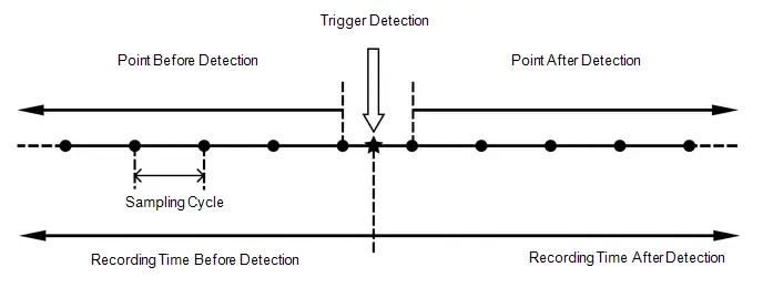 When "Emergency Driving Stop System Control / Pre-collision / Parking Support Brake Control / Airbag Control Operation History"
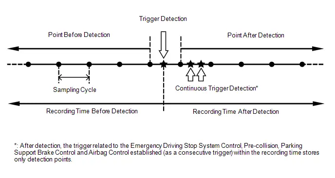 Record Data Specifications
 | Trigger Item | Record Data | |||||
|---|---|---|---|---|---|---|
| Before Detection | After Detection | Sampling Cycle (sec.) | ||||
| ID No. | Item | Recording Time (sec.) | Number of Points | Recording Time (sec.) | Number of Points | |
| 2 | Accelerator pedal opening angle signal is high during low speed | 7.5 | 15 | 7.5 | 16 | 0.5 |
| 3 | Accelerator high position in mid to high speed | 7.5 | 15 | 7.5 | 16 | 0.5 |
| 4 | Accelerator pedal opening angle signal is high immediately after brake pedal is released | 7.5 | 15 | 7.5 | 16 | 0.5 |
| 5-1 | Accelerator pedal opening angle is medium or higher immediately after shifting to R | 5 | 10 | 5 | 11 | 0.5 |
| 5-2 | Accelerator pedal opening angle is medium or higher immediately after shifting to forward position | |||||
| 5-3 | Accelerator pedal opening angle is medium or higher immediately after shifting to driving position | |||||
| 6-1 | R position signal input during medium or higher accelerator signal input | 5 | 10 | 5 | 11 | 0.5 |
| 6-2 | Forward position signal input during medium or higher accelerator signal input | |||||
| 6-3 | Driving position signal input during medium or higher accelerator signal input | |||||
| 8 | Accelerator signal and brake signal input simultaneously | 5 | 10 | 5 | 11 | 0.5 |
| 9 | Medium or higher accelerator signal input immediately after switching to D or R | 5 | 10 | 5 | 11 | 0.5 |
| 10 | Medium or higher accelerator signal input during N | 5 | 10 | 5 | 11 | 0.5 |
| 12 | VSC operation history | 5 | 34 | 5 | 35 | 0.15 |
| 13 | TRC operation history | 5 | 34 | 5 | 35 | 0.15 |
| 14 | ABS operation history | 5 | 34 | 5 | 35 | 0.15 |
| 15 | Sudden braking history | 5 | 34 | 5 | 35 | 0.15 |
| 16 | Sudden turning history | 5 | 34 | 5 | 35 | 0.15 |
| 17 | Input accelerator in ACC/CC | 5 | 10 | 5 | 11 | 0.5 |
| 18-1 | PCS operation history (warning buzzer operation) | 5 | 10 | 4 | 9 | 0.5 |
| 18-2 | PCS operation history (Emergency Steering Assist operation) | |||||
| 18-3 | PCS operation history (pre-collision brake assist operation) | |||||
| 18-4 | PCS operation history (prior brake operation) | |||||
| 18-5 | PCS operation history (pre-collision brake operation) | |||||
| 18-6 | PCS operation history (pre-collision seat belt operation) | |||||
| 18-7 | PCS operation history (pre-pump operation) | |||||
| 18-8 | PCS operation history (PBR operation) | |||||
| 18-9 | PCS operation history (PBH operation) | |||||
| 18-10 | PCS operation history (avoidance support) | |||||
| 18-12 | PCS operation history (request combined steering) | |||||
| 18-14 | Pedestrian Protection System Over Constant Pressure Sensor Signal Input | |||||
| 18-15 | PCS operation history (side airbag operation request) | |||||
| 19 | Steering angle speed threshold exceeded | 4 | 10 | 4 | 11 | 0.4 |
| 20-1 | PKSB operation history (output limit) | 5 | 10 | 5 | 11 | 0.5 |
| 20-2 | PKSB operation history (max output limit) | |||||
| 20-3 | PKSB operation history (brake control) | |||||
| 20-4 | PKSB operation history (stop) | |||||
| 20-5 | PKSB operation history (regression) | |||||
| 20-6 | PKSB operation history (temporarily not available) | |||||
| 22 | Lane Change Assist operation history | 8 | 20 | 4 | 11 | 0.4 |
| 23-1 | FHL operation history | 5 | 25 | 3 | 16 | 0.2 |
| 23-2 | Secondary Collision Brake (Rear impacts while stopped) operation history | |||||
| 23-3 | Rear Toyota Prius Vehicle Approaching Indication operation history | |||||
| 23-4 | Approaching Vehicle Support operation history | |||||
| 24-1 | SCB operation history | 5 | 34 | 5 | 35 | 0.15 |
| 24-2 | Post-Collision acceleration restriction | |||||
| 25 | Acceleration above certain amount is detected | 8 | 16 | 5 | 11 | 0.5 |
| 26-1 | Emergency Driving Stop System History (Shift to Deceleration phase) | 2 | 4 | 5 | 11 | 0.5 |
| 26-2 | Emergency Driving Stop System History (Shift to Stop phase) | |||||
| 26-3 | Emergency Driving Stop System History (Cancelation from Warning phase) | |||||
| 26-4 | Emergency Driving Stop System History (Cancelation from Speed restraint phase) | |||||
| 26-5 | Emergency Driving Stop System History (Cancelation from Deceleration phase) | |||||
| 26-6 | Emergency Driving Stop System History (Cancelation from Stop phase) | |||||
| 27-1 | SOS Button Triggered | 7.5 | 15 | 5 | 11 | 0.5 |
| 27-2 | EPB Dynamic Deceleration Active | |||||
| 27-3 | EPB Dynamic Deceleration Inactive | |||||
| 29-1 | SRS Airbag System Over Constant Sensor Signal Input (Longitudinal) | 5 | 10 | 5 | 11 | 0.5 |
| 29-2 | SRS Airbag System Over Constant Sensor Signal Input (Lateral) | |||||
| 30 | ACC Deceleration | 7.5 | 15 | 2.5 | 6 | 0.5 |
| 31 | Step on accelerator pedal quickly in low to mid speed and accelerator pedal opening angle high | 3 | 20 | 5 | 35 | 0.15 |
| 32-1 | Impact detection with vulnerable road users (pedestrian or two-wheeled Toyota Prius vehicle) | 5 | 34 | 5 | 35 | 0.15 |
| 32-2 | PCS judgment for vulnerable road users impact detection system | |||||
| 32-3 | Front sensor judgment for vulnerable road users impact detection system | |||||
| 33 | ACC cancel after resume | 7.5 | 15 | 2.5 | 6 | 0.5 |
| Trigger Item | Image Recording ECU | Record Data | |||||
|---|---|---|---|---|---|---|---|
| Before Detection | After Detection | Sampling Cycle (sec.) | |||||
| ID No. | Item | Recording Time (sec.) | Number of Points | Recording Time (sec.) | Number of Points | ||
|
*1: w/ Panoramic View Monitor System
*2: w/o Panoramic View Monitor System | |||||||
| 15 | Sudden braking history | Forward recognition camera | 6 | 10 | 6 | 10 | 0.6 |
| 16 | Sudden turning history | Forward recognition camera | 6 | 10 | 6 | 10 | 0.6 |
| 18-1 | PCS operation history (warning buzzer operation) | Forward recognition camera | 2.4 | 4 | - | - | 0.6 |
| 18-2 | PCS operation history (Emergency Steering Assist operation) | Forward recognition camera | 6 | 10 | 6 | 10 | 0.6 |
| 18-3 | PCS operation history (pre-collision brake assist operation) | ||||||
| 18-4 | PCS operation history (prior brake operation) | ||||||
| 18-5 | PCS operation history (pre-collision brake operation) | ||||||
| 18-14 | Pedestrian Protection System Over Constant Pressure Sensor Signal Input | ||||||
| 19 | Steering angle speed threshold exceeded | Forward recognition camera | 6 | 10 | 6 | 10 | 0.6 |
| 20-2 | PKSB operation history (max output limit) | Forward recognition camera | 6 | 10 | 6 | 10 | 0.6 |
| Parking assist ECU*1 | 3 | 10 | 3 | 10 | 0.3 | ||
| Parking assist ECU*2 | 1.8 | 3 | 0.6 | 1 | 0.6 | ||
| 20-3 | PKSB operation history (brake control) | Forward recognition camera | 6 | 10 | 6 | 10 | 0.6 |
| Parking assist ECU*1 | 3 | 10 | 3 | 10 | 0.3 | ||
| Parking assist ECU*2 | 1.8 | 3 | 0.6 | 1 | 0.6 | ||
| 23-1 | FHL operation history | Forward recognition camera | 3.6 | 3 | 3.6 | 3 | 1.2 |
| 23-2 | Secondary Collision Brake (Rear impacts while stopped) operation history | ||||||
| 23-3 | Rear Toyota Prius Vehicle Approaching Indication operation history | ||||||
| 23-4 | Approaching Vehicle Support operation history | ||||||
| 25 | Acceleration above certain amount is detected | Forward recognition camera | 6 | 10 | 6 | 10 | 0.6 |
| Parking assist ECU*1 | 6 | 10 | 6 | 10 | 0.6 | ||
| Parking assist ECU*2 | 1.2 | 2 | 0.6 | 1 | 0.6 | ||
| 27-1 | SOS Button Triggered | Forward recognition camera | 6 | 10 | 6 | 10 | 0.6 |
| 27-2 | EPB Dynamic Deceleration Active | Forward recognition camera | |||||
| 27-3 | EPB Dynamic Deceleration Inactive | Forward recognition camera | |||||
| 30 | ACC Deceleration | Forward recognition camera | 3.6 | 3 | 0 | 0 | 1.2 |
| 33 | ACC cancel after resume | Forward recognition camera | 3.6 | 3 | 0 | 0 | 1.2 |
| Tester Display | Trigger ID No. |
|---|---|
| Toyota Prius Vehicle Speed | 2, 3, 4, 5-1, 5-2, 5-3, 6-1, 6-2, 6-3, 8, 9, 10, 12, 13, 14, 15, 16, 17, 18-1, 18-2, 18-3, 18-4, 18-5, 18-6, 18-7, 18-8, 18-9, 18-10, 18-12, 18-14, 18-15, 19, 20-1, 20-2, 20-3, 20-4, 20-5, 20-6, 22, 23-1, 23-2 , 23-3, 23-4, 24-1, 24-2, 25, 26-1, 26-2, 26-3, 26-4, 26-5, 26-6, 27-1, 27-2, 27-3, 29-1, 29-2, 30, 31, 32-1, 32-2, 32-3, 33 |
| Accelerator Opening Ratio | 2, 3, 4, 5-1, 5-2, 5-3, 6-1, 6-2, 6-3, 8, 9, 10, 12, 13, 14, 15, 16, 17, 18-1, 18-2, 18-3, 18-4, 18-5, 18-6, 18-7, 18-8, 18-9, 18-10, 18-12, 18-14, 18-15, 19, 20-1, 20-2, 20-3, 20-4, 20-5, 20-6, 22, 23-1, 23-2 , 23-3, 23-4, 24-1, 24-2, 25, 26-1, 26-2, 26-3, 26-4, 26-5, 26-6, 27-1, 27-2, 27-3, 29-1, 29-2, 30, 31, 32-1, 32-2, 32-3, 33 |
| Engine RPM Data | 2, 3, 4, 5-1, 5-2, 5-3, 6-1, 6-2, 6-3, 8, 9, 10, 12, 13, 14, 15, 16, 17, 18-1, 18-2, 18-3, 18-4, 18-5, 18-6, 18-7, 18-8, 18-9, 18-10, 18-12, 18-14, 18-15, 19, 20-1, 20-2, 20-3, 20-4, 20-5, 20-6, 22, 23-1, 23-2 , 23-3, 23-4, 24-1, 24-2, 25, 26-1, 26-2, 26-3, 26-4, 26-5, 26-6, 27-1, 27-2, 27-3, 29-1, 29-2, 30, 31, 32-1, 32-2, 32-3, 33 |
| Shift Position Signal | 2, 3, 4, 5-1, 5-2, 5-3, 6-1, 6-2, 6-3, 8, 9, 10, 12, 13, 14, 15, 16, 17, 18-1, 18-2, 18-3, 18-4, 18-5, 18-6, 18-7, 18-8, 18-9, 18-10, 18-12, 18-14, 18-15, 19, 20-1, 20-2, 20-3, 20-4, 20-5, 20-6, 22, 23-1, 23-2 , 23-3, 23-4, 24-1, 24-2, 25, 26-1, 26-2, 26-3, 26-4, 26-5, 26-6, 27-1, 27-2, 27-3, 29-1, 29-2, 30, 31, 32-1, 32-2, 32-3, 33 |
| Brake SW | 2, 3, 4, 5-1, 5-2, 5-3, 6-1, 6-2, 6-3, 8, 9, 10, 12, 13, 14, 15, 16, 17, 18-1, 18-2, 18-3, 18-4, 18-5, 18-6, 18-7, 18-8, 18-9, 18-10, 18-12, 18-14, 18-15, 19, 20-1, 20-2, 20-3, 20-4, 20-5, 20-6, 22, 23-1, 23-2 , 23-3, 23-4, 24-1, 24-2, 25, 26-1, 26-2, 26-3, 26-4, 26-5, 26-6, 27-1, 27-2, 27-3, 29-1, 29-2, 30, 31, 32-1, 32-2, 32-3, 33 |
| Brake Oil Pressure | 2, 3, 4, 5-1, 5-2, 5-3, 6-1, 6-2, 6-3, 8, 9, 10, 12, 13, 14, 15, 16, 17, 18-1, 18-2, 18-3, 18-4, 18-5, 18-6, 18-7, 18-8, 18-9, 18-10, 18-12, 18-14, 18-15, 19, 20-1, 20-2, 20-3, 20-4, 20-5, 20-6, 22, 23-1, 23-2 , 23-3, 23-4, 24-1, 24-2, 25, 26-1, 26-2, 26-3, 26-4, 26-5, 26-6, 27-1, 27-2, 27-3, 29-1, 29-2, 30, 31, 32-1, 32-2, 32-3, 33 |
| Driver Operate Brake Torque | 2, 3, 4, 5-1, 5-2, 5-3, 6-1, 6-2, 6-3, 8, 9, 10, 12, 13, 14, 15, 16, 17, 18-1, 18-2, 18-3, 18-4, 18-5, 18-6, 18-7, 18-8, 18-9, 18-10, 18-12, 18-14, 18-15, 19, 20-1, 20-2, 20-3, 20-4, 20-5, 20-6, 22, 23-1, 23-2 , 23-3, 23-4, 24-1, 24-2, 25, 26-1, 26-2, 26-3, 26-4, 26-5, 26-6, 27-1, 27-2, 27-3, 29-1, 29-2, 30, 31, 32-1, 32-2, 32-3, 33 |
| Yaw Rate Sensor Signal | 2, 3, 4, 5-1, 5-2, 5-3, 6-1, 6-2, 6-3, 8, 9, 10, 12, 13, 14, 15, 16, 17, 18-1, 18-2, 18-3, 18-4, 18-5, 18-6, 18-7, 18-8, 18-9, 18-10, 18-12, 18-14, 18-15, 19, 20-1, 20-2, 20-3, 20-4, 20-5, 20-6, 22, 23-1, 23-2 , 23-3, 23-4, 24-1, 24-2, 25, 26-1, 26-2, 26-3, 26-4, 26-5, 26-6, 27-1, 27-2, 27-3, 29-1, 29-2, 30, 31, 32-1, 32-2, 32-3, 33 |
| Longitudinal G Sensor Signal | 2, 3, 4, 5-1, 5-2, 5-3, 6-1, 6-2, 6-3, 8, 9, 10, 12, 13, 14, 15, 16, 17, 18-1, 18-2, 18-3, 18-4, 18-5, 18-6, 18-7, 18-8, 18-9, 18-10, 18-12, 18-14, 18-15, 19, 20-1, 20-2, 20-3, 20-4, 20-5, 20-6, 22, 23-1, 23-2 , 23-3, 23-4, 24-1, 24-2, 25, 26-1, 26-2, 26-3, 26-4, 26-5, 26-6, 27-1, 27-2, 27-3, 29-1, 29-2, 30, 31, 32-1, 32-2, 32-3, 33 |
| Lateral G Sensor Signal | 2, 3, 4, 5-1, 5-2, 5-3, 6-1, 6-2, 6-3, 8, 9, 10, 12, 13, 14, 15, 16, 17, 18-1, 18-2, 18-3, 18-4, 18-5, 18-6, 18-7, 18-8, 18-9, 18-10, 18-12, 18-14, 18-15, 19, 20-1, 20-2, 20-3, 20-4, 20-5, 20-6, 22, 23-1, 23-2 , 23-3, 23-4, 24-1, 24-2, 25, 26-1, 26-2, 26-3, 26-4, 26-5, 26-6, 27-1, 27-2, 27-3, 29-1, 29-2, 30, 31, 32-1, 32-2, 32-3, 33 |
| Throttle Opening Ratio | 2, 3, 4, 5-1, 5-2, 5-3, 6-1, 6-2, 6-3, 8, 9, 10, 12, 13, 14, 15, 16, 17, 18-1, 18-2, 18-3, 18-4, 18-5, 18-6, 18-7, 18-8, 18-9, 18-10, 18-12, 18-14, 18-15, 19, 20-1, 20-2, 20-3, 20-4, 20-5, 20-6, 22, 23-1, 23-2 , 23-3, 23-4, 24-1, 24-2, 25, 26-1, 26-2, 26-3, 26-4, 26-5, 26-6, 27-1, 27-2, 27-3, 29-1, 29-2, 30, 31, 32-1, 32-2, 32-3, 33 |
| Command Value of Fuel Injection Amount | 2, 3, 4, 5-1, 5-2, 5-3, 6-1, 6-2, 6-3, 8, 9, 10, 12, 13, 14, 15, 16, 17, 18-1, 18-2, 18-3, 18-4, 18-5, 18-6, 18-7, 18-8, 18-9, 18-10, 18-12, 18-14, 18-15, 19, 20-1, 20-2, 20-3, 20-4, 20-5, 20-6, 22, 23-1, 23-2 , 23-3, 23-4, 24-1, 24-2, 25, 26-1, 26-2, 26-3, 26-4, 26-5, 26-6, 27-1, 27-2, 27-3, 29-1, 29-2, 30, 31, 32-1, 32-2, 32-3, 33 |
| Steering Signal | 2, 3, 4, 5-1, 5-2, 5-3, 6-1, 6-2, 6-3, 8, 9, 10, 12, 13, 14, 15, 16, 17, 18-1, 18-2, 18-3, 18-4, 18-5, 18-6, 18-7, 18-8, 18-9, 18-10, 18-12, 18-14, 18-15, 19, 20-1, 20-2, 20-3, 20-4, 20-5, 20-6, 22, 23-1, 23-2 , 23-3, 23-4, 24-1, 24-2, 25, 26-1, 26-2, 26-3, 26-4, 26-5, 26-6, 27-1, 27-2, 27-3, 29-1, 29-2, 30, 31, 32-1, 32-2, 32-3, 33 |
| Cruise Data Reception Status | 2, 3, 4, 5-1, 5-2, 5-3, 6-1, 6-2, 6-3, 8, 9, 10, 12, 13, 14, 15, 16, 17, 18-1, 18-2, 18-3, 18-4, 18-5, 18-6, 18-7, 18-8, 18-9, 18-10, 18-12, 18-14, 18-15, 19, 20-1, 20-2, 20-3, 20-4, 20-5, 20-6, 22, 23-1, 23-2 , 23-3, 23-4, 24-1, 24-2, 25, 26-1, 26-2, 26-3, 26-4, 26-5, 26-6, 27-1, 27-2, 27-3, 29-1, 29-2, 30, 31, 32-1, 32-2, 32-3, 33 |
| PCS_ON/OFF_SW State | 2, 3, 4, 5-1, 5-2, 5-3, 6-1, 6-2, 6-3, 8, 9, 10, 12, 13, 14, 15, 16, 17, 18-1, 18-2, 18-3, 18-4, 18-5, 18-6, 18-7, 18-8, 18-9, 18-10, 18-12, 18-14, 18-15, 19, 20-1, 20-2, 20-3, 20-4, 20-5, 20-6, 22, 23-1, 23-2 , 23-3, 23-4, 24-1, 24-2, 25, 26-1, 26-2, 26-3, 26-4, 26-5, 26-6, 27-1, 27-2, 27-3, 29-1, 29-2, 30, 31, 32-1, 32-2, 32-3, 33 |
| PCS FPB Request Flag | 2, 3, 4, 5-1, 5-2, 5-3, 6-1, 6-2, 6-3, 8, 9, 10, 12, 13, 14, 15, 16, 17, 18-1, 18-2, 18-3, 18-4, 18-5, 18-6, 18-7, 18-8, 18-9, 18-10, 18-12, 18-14, 18-15, 19, 20-1, 20-2, 20-3, 20-4, 20-5, 20-6, 22, 23-1, 23-2 , 23-3, 23-4, 24-1, 24-2, 25, 26-1, 26-2, 26-3, 26-4, 26-5, 26-6, 27-1, 27-2, 27-3, 29-1, 29-2, 30, 31, 32-1, 32-2, 32-3, 33 |
| Cruise Control | 2, 3, 4, 5-1, 5-2, 5-3, 6-1, 6-2, 6-3, 8, 9, 10, 12, 13, 14, 15, 16, 17, 18-1, 18-2, 18-3, 18-4, 18-5, 18-6, 18-7, 18-8, 18-9, 18-10, 18-12, 18-14, 18-15, 19, 20-1, 20-2, 20-3, 20-4, 20-5, 20-6, 22, 23-1, 23-2 , 23-3, 23-4, 24-1, 24-2, 25, 26-1, 26-2, 26-3, 26-4, 26-5, 26-6, 27-1, 27-2, 27-3, 29-1, 29-2, 30, 31, 32-1, 32-2, 32-3, 33 |
| Under VSC Control | 2, 3, 4, 5-1, 5-2, 5-3, 6-1, 6-2, 6-3, 8, 9, 10, 12, 13, 14, 15, 16, 17, 18-1, 18-2, 18-3, 18-4, 18-5, 18-6, 18-7, 18-8, 18-9, 18-10, 18-12, 18-14, 18-15, 19, 20-1, 20-2, 20-3, 20-4, 20-5, 20-6, 22, 23-1, 23-2 , 23-3, 23-4, 24-1, 24-2, 25, 26-1, 26-2, 26-3, 26-4, 26-5, 26-6, 27-1, 27-2, 27-3, 29-1, 29-2, 30, 31, 32-1, 32-2, 32-3, 33 |
| Under ABS Control | 2, 3, 4, 5-1, 5-2, 5-3, 6-1, 6-2, 6-3, 8, 9, 10, 12, 13, 14, 15, 16, 17, 18-1, 18-2, 18-3, 18-4, 18-5, 18-6, 18-7, 18-8, 18-9, 18-10, 18-12, 18-14, 18-15, 19, 20-1, 20-2, 20-3, 20-4, 20-5, 20-6, 22, 23-1, 23-2 , 23-3, 23-4, 24-1, 24-2, 25, 26-1, 26-2, 26-3, 26-4, 26-5, 26-6, 27-1, 27-2, 27-3, 29-1, 29-2, 30, 31, 32-1, 32-2, 32-3, 33 |
| Under BOS Control | 2, 3, 4, 5-1, 5-2, 5-3, 6-1, 6-2, 6-3, 8, 9, 10, 12, 13, 14, 15, 16, 17, 18-1, 18-2, 18-3, 18-4, 18-5, 18-6, 18-7, 18-8, 18-9, 18-10, 18-12, 18-14, 18-15, 19, 20-1, 20-2, 20-3, 20-4, 20-5, 20-6, 22, 23-1, 23-2 , 23-3, 23-4, 24-1, 24-2, 25, 26-1, 26-2, 26-3, 26-4, 26-5, 26-6, 27-1, 27-2, 27-3, 29-1, 29-2, 30, 31, 32-1, 32-2, 32-3, 33 |
| Under TRC Operation Flag | 2, 3, 4, 5-1, 5-2, 5-3, 6-1, 6-2, 6-3, 8, 9, 10, 12, 13, 14, 15, 16, 17, 18-1, 18-2, 18-3, 18-4, 18-5, 18-6, 18-7, 18-8, 18-9, 18-10, 18-12, 18-14, 18-15, 19, 20-1, 20-2, 20-3, 20-4, 20-5, 20-6, 22, 23-1, 23-2 , 23-3, 23-4, 24-1, 24-2, 25, 26-1, 26-2, 26-3, 26-4, 26-5, 26-6, 27-1, 27-2, 27-3, 29-1, 29-2, 30, 31, 32-1, 32-2, 32-3, 33 |
| PCS Reception Data Invalid Flag | 2, 3, 4, 5-1, 5-2, 5-3, 6-1, 6-2, 6-3, 8, 9, 10, 12, 13, 14, 15, 16, 17, 18-1, 18-2, 18-3, 18-4, 18-5, 18-6, 18-7, 18-8, 18-9, 18-10, 18-12, 18-14, 18-15, 19, 20-1, 20-2, 20-3, 20-4, 20-5, 20-6, 22, 23-1, 23-2 , 23-3, 23-4, 24-1, 24-2, 25, 26-1, 26-2, 26-3, 26-4, 26-5, 26-6, 27-1, 27-2, 27-3, 29-1, 29-2, 30, 31, 32-1, 32-2, 32-3, 33 |
| PCS ALM Request Flag (PRE ALM Request) | 2, 3, 4, 5-1, 5-2, 5-3, 6-1, 6-2, 6-3, 8, 9, 10, 12, 13, 14, 15, 16, 17, 18-1, 18-2, 18-3, 18-4, 18-5, 18-6, 18-7, 18-8, 18-9, 18-10, 18-12, 18-14, 18-15, 19, 20-1, 20-2, 20-3, 20-4, 20-5, 20-6, 22, 23-1, 23-2 , 23-3, 23-4, 24-1, 24-2, 25, 26-1, 26-2, 26-3, 26-4, 26-5, 26-6, 27-1, 27-2, 27-3, 29-1, 29-2, 30, 31, 32-1, 32-2, 32-3, 33 |
| PCS ALM Request Flag (Ordinary ALM Request) | 2, 3, 4, 5-1, 5-2, 5-3, 6-1, 6-2, 6-3, 8, 9, 10, 12, 13, 14, 15, 16, 17, 18-1, 18-2, 18-3, 18-4, 18-5, 18-6, 18-7, 18-8, 18-9, 18-10, 18-12, 18-14, 18-15, 19, 20-1, 20-2, 20-3, 20-4, 20-5, 20-6, 22, 23-1, 23-2 , 23-3, 23-4, 24-1, 24-2, 25, 26-1, 26-2, 26-3, 26-4, 26-5, 26-6, 27-1, 27-2, 27-3, 29-1, 29-2, 30, 31, 32-1, 32-2, 32-3, 33 |
| PCS PBA Request Flag | 2, 3, 4, 5-1, 5-2, 5-3, 6-1, 6-2, 6-3, 8, 9, 10, 12, 13, 14, 15, 16, 17, 18-1, 18-2, 18-3, 18-4, 18-5, 18-6, 18-7, 18-8, 18-9, 18-10, 18-12, 18-14, 18-15, 19, 20-1, 20-2, 20-3, 20-4, 20-5, 20-6, 22, 23-1, 23-2 , 23-3, 23-4, 24-1, 24-2, 25, 26-1, 26-2, 26-3, 26-4, 26-5, 26-6, 27-1, 27-2, 27-3, 29-1, 29-2, 30, 31, 32-1, 32-2, 32-3, 33 |
| PCS PB Request Flag | 2, 3, 4, 5-1, 5-2, 5-3, 6-1, 6-2, 6-3, 8, 9, 10, 12, 13, 14, 15, 16, 17, 18-1, 18-2, 18-3, 18-4, 18-5, 18-6, 18-7, 18-8, 18-9, 18-10, 18-12, 18-14, 18-15, 19, 20-1, 20-2, 20-3, 20-4, 20-5, 20-6, 22, 23-1, 23-2 , 23-3, 23-4, 24-1, 24-2, 25, 26-1, 26-2, 26-3, 26-4, 26-5, 26-6, 27-1, 27-2, 27-3, 29-1, 29-2, 30, 31, 32-1, 32-2, 32-3, 33 |
| PCS Display (Control Status 2) | 2, 3, 4, 5-1, 5-2, 5-3, 6-1, 6-2, 6-3, 8, 9, 10, 12, 13, 14, 15, 16, 17, 18-1, 18-2, 18-3, 18-4, 18-5, 18-6, 18-7, 18-8, 18-9, 18-10, 18-12, 18-14, 18-15, 19, 20-1, 20-2, 20-3, 20-4, 20-5, 20-6, 22, 23-1, 23-2 , 23-3, 23-4, 24-1, 24-2, 25, 26-1, 26-2, 26-3, 26-4, 26-5, 26-6, 27-1, 27-2, 27-3, 29-1, 29-2, 30, 31, 32-1, 32-2, 32-3, 33 |
| PCS Display (Control Status 1) | 2, 3, 4, 5-1, 5-2, 5-3, 6-1, 6-2, 6-3, 8, 9, 10, 12, 13, 14, 15, 16, 17, 18-1, 18-2, 18-3, 18-4, 18-5, 18-6, 18-7, 18-8, 18-9, 18-10, 18-12, 18-14, 18-15, 19, 20-1, 20-2, 20-3, 20-4, 20-5, 20-6, 22, 23-1, 23-2 , 23-3, 23-4, 24-1, 24-2, 25, 26-1, 26-2, 26-3, 26-4, 26-5, 26-6, 27-1, 27-2, 27-3, 29-1, 29-2, 30, 31, 32-1, 32-2, 32-3, 33 |
| PCS Display (Object Recognition Status) | 2, 3, 4, 5-1, 5-2, 5-3, 6-1, 6-2, 6-3, 8, 9, 10, 12, 13, 14, 15, 16, 17, 18-1, 18-2, 18-3, 18-4, 18-5, 18-6, 18-7, 18-8, 18-9, 18-10, 18-12, 18-14, 18-15, 19, 20-1, 20-2, 20-3, 20-4, 20-5, 20-6, 22, 23-1, 23-2 , 23-3, 23-4, 24-1, 24-2, 25, 26-1, 26-2, 26-3, 26-4, 26-5, 26-6, 27-1, 27-2, 27-3, 29-1, 29-2, 30, 31, 32-1, 32-2, 32-3, 33 |
| PCS Display (Milli-Meter Wave Radar Alignment Flag) | 2, 3, 4, 5-1, 5-2, 5-3, 6-1, 6-2, 6-3, 8, 9, 10, 12, 13, 14, 15, 16, 17, 18-1, 18-2, 18-3, 18-4, 18-5, 18-6, 18-7, 18-8, 18-9, 18-10, 18-12, 18-14, 18-15, 19, 20-1, 20-2, 20-3, 20-4, 20-5, 20-6, 22, 23-1, 23-2 , 23-3, 23-4, 24-1, 24-2, 25, 26-1, 26-2, 26-3, 26-4, 26-5, 26-6, 27-1, 27-2, 27-3, 29-1, 29-2, 30, 31, 32-1, 32-2, 32-3, 33 |
| PCS Display (Camera Backlight Status) | 2, 3, 4, 5-1, 5-2, 5-3, 6-1, 6-2, 6-3, 8, 9, 10, 12, 13, 14, 15, 16, 17, 18-1, 18-2, 18-3, 18-4, 18-5, 18-6, 18-7, 18-8, 18-9, 18-10, 18-12, 18-14, 18-15, 19, 20-1, 20-2, 20-3, 20-4, 20-5, 20-6, 22, 23-1, 23-2 , 23-3, 23-4, 24-1, 24-2, 25, 26-1, 26-2, 26-3, 26-4, 26-5, 26-6, 27-1, 27-2, 27-3, 29-1, 29-2, 30, 31, 32-1, 32-2, 32-3, 33 |
| PCS Display (Milli-Meter Wave Radar Low Voltage Status) | 2, 3, 4, 5-1, 5-2, 5-3, 6-1, 6-2, 6-3, 8, 9, 10, 12, 13, 14, 15, 16, 17, 18-1, 18-2, 18-3, 18-4, 18-5, 18-6, 18-7, 18-8, 18-9, 18-10, 18-12, 18-14, 18-15, 19, 20-1, 20-2, 20-3, 20-4, 20-5, 20-6, 22, 23-1, 23-2 , 23-3, 23-4, 24-1, 24-2, 25, 26-1, 26-2, 26-3, 26-4, 26-5, 26-6, 27-1, 27-2, 27-3, 29-1, 29-2, 30, 31, 32-1, 32-2, 32-3, 33 |
| PCS Display (Sensor Recognition Status) | 2, 3, 4, 5-1, 5-2, 5-3, 6-1, 6-2, 6-3, 8, 9, 10, 12, 13, 14, 15, 16, 17, 18-1, 18-2, 18-3, 18-4, 18-5, 18-6, 18-7, 18-8, 18-9, 18-10, 18-12, 18-14, 18-15, 19, 20-1, 20-2, 20-3, 20-4, 20-5, 20-6, 22, 23-1, 23-2 , 23-3, 23-4, 24-1, 24-2, 25, 26-1, 26-2, 26-3, 26-4, 26-5, 26-6, 27-1, 27-2, 27-3, 29-1, 29-2, 30, 31, 32-1, 32-2, 32-3, 33 |
| PCS Display (Temporarily not available) | 2, 3, 4, 5-1, 5-2, 5-3, 6-1, 6-2, 6-3, 8, 9, 10, 12, 13, 14, 15, 16, 17, 18-1, 18-2, 18-3, 18-4, 18-5, 18-6, 18-7, 18-8, 18-9, 18-10, 18-12, 18-14, 18-15, 19, 20-1, 20-2, 20-3, 20-4, 20-5, 20-6, 22, 23-1, 23-2 , 23-3, 23-4, 24-1, 24-2, 25, 26-1, 26-2, 26-3, 26-4, 26-5, 26-6, 27-1, 27-2, 27-3, 29-1, 29-2, 30, 31, 32-1, 32-2, 32-3, 33 |
| PCS Display (Milli-Meter Wave Radar Dirt) | 2, 3, 4, 5-1, 5-2, 5-3, 6-1, 6-2, 6-3, 8, 9, 10, 12, 13, 14, 15, 16, 17, 18-1, 18-2, 18-3, 18-4, 18-5, 18-6, 18-7, 18-8, 18-9, 18-10, 18-12, 18-14, 18-15, 19, 20-1, 20-2, 20-3, 20-4, 20-5, 20-6, 22, 23-1, 23-2 , 23-3, 23-4, 24-1, 24-2, 25, 26-1, 26-2, 26-3, 26-4, 26-5, 26-6, 27-1, 27-2, 27-3, 29-1, 29-2, 30, 31, 32-1, 32-2, 32-3, 33 |
| PCS Display (Diag Condition) | 2, 3, 4, 5-1, 5-2, 5-3, 6-1, 6-2, 6-3, 8, 9, 10, 12, 13, 14, 15, 16, 17, 18-1, 18-2, 18-3, 18-4, 18-5, 18-6, 18-7, 18-8, 18-9, 18-10, 18-12, 18-14, 18-15, 19, 20-1, 20-2, 20-3, 20-4, 20-5, 20-6, 22, 23-1, 23-2 , 23-3, 23-4, 24-1, 24-2, 25, 26-1, 26-2, 26-3, 26-4, 26-5, 26-6, 27-1, 27-2, 27-3, 29-1, 29-2, 30, 31, 32-1, 32-2, 32-3, 33 |
| LDA Data Reception Status | 2, 3, 4, 5-1, 5-2, 5-3, 6-1, 6-2, 6-3, 8, 9, 10, 12, 13, 14, 15, 16, 17, 18-1, 18-2, 18-3, 18-4, 18-5, 18-6, 18-7, 18-8, 18-9, 18-10, 18-12, 18-14, 18-15, 19, 20-1, 20-2, 20-3, 20-4, 20-5, 20-6, 22, 23-1, 23-2 , 23-3, 23-4, 24-1, 24-2, 25, 26-1, 26-2, 26-3, 26-4, 26-5, 26-6, 27-1, 27-2, 27-3, 29-1, 29-2, 30, 31, 32-1, 32-2, 32-3, 33 |
| LTA Data Reception Status | 2, 3, 4, 5-1, 5-2, 5-3, 6-1, 6-2, 6-3, 8, 9, 10, 12, 13, 14, 15, 16, 17, 18-1, 18-2, 18-3, 18-4, 18-5, 18-6, 18-7, 18-8, 18-9, 18-10, 18-12, 18-14, 18-15, 19, 20-1, 20-2, 20-3, 20-4, 20-5, 20-6, 22, 23-1, 23-2 , 23-3, 23-4, 24-1, 24-2, 25, 26-1, 26-2, 26-3, 26-4, 26-5, 26-6, 27-1, 27-2, 27-3, 29-1, 29-2, 30, 31, 32-1, 32-2, 32-3, 33 |
| LCA Data Reception Status | 2, 3, 4, 5-1, 5-2, 5-3, 6-1, 6-2, 6-3, 8, 9, 10, 12, 13, 14, 15, 16, 17, 18-1, 18-2, 18-3, 18-4, 18-5, 18-6, 18-7, 18-8, 18-9, 18-10, 18-12, 18-14, 18-15, 19, 20-1, 20-2, 20-3, 20-4, 20-5, 20-6, 22, 23-1, 23-2 , 23-3, 23-4, 24-1, 24-2, 25, 26-1, 26-2, 26-3, 26-4, 26-5, 26-6, 27-1, 27-2, 27-3, 29-1, 29-2, 30, 31, 32-1, 32-2, 32-3, 33 |
| Emergency Driving Stop System Data Reception Status | 2, 3, 4, 5-1, 5-2, 5-3, 6-1, 6-2, 6-3, 8, 9, 10, 12, 13, 14, 15, 16, 17, 18-1, 18-2, 18-3, 18-4, 18-5, 18-6, 18-7, 18-8, 18-9, 18-10, 18-12, 18-14, 18-15, 19, 20-1, 20-2, 20-3, 20-4, 20-5, 20-6, 22, 23-1, 23-2 , 23-3, 23-4, 24-1, 24-2, 25, 26-1, 26-2, 26-3, 26-4, 26-5, 26-6, 27-1, 27-2, 27-3, 29-1, 29-2, 30, 31, 32-1, 32-2, 32-3, 33 |
| Lane Departure Prevention Control | 2, 3, 4, 5-1, 5-2, 5-3, 6-1, 6-2, 6-3, 8, 9, 10, 12, 13, 14, 15, 16, 17, 18-1, 18-2, 18-3, 18-4, 18-5, 18-6, 18-7, 18-8, 18-9, 18-10, 18-12, 18-14, 18-15, 19, 20-1, 20-2, 20-3, 20-4, 20-5, 20-6, 22, 23-1, 23-2 , 23-3, 23-4, 24-1, 24-2, 25, 26-1, 26-2, 26-3, 26-4, 26-5, 26-6, 27-1, 27-2, 27-3, 29-1, 29-2, 30, 31, 32-1, 32-2, 32-3, 33 |
| Lane Departure Monitoring | 2, 3, 4, 5-1, 5-2, 5-3, 6-1, 6-2, 6-3, 8, 9, 10, 12, 13, 14, 15, 16, 17, 18-1, 18-2, 18-3, 18-4, 18-5, 18-6, 18-7, 18-8, 18-9, 18-10, 18-12, 18-14, 18-15, 19, 20-1, 20-2, 20-3, 20-4, 20-5, 20-6, 22, 23-1, 23-2 , 23-3, 23-4, 24-1, 24-2, 25, 26-1, 26-2, 26-3, 26-4, 26-5, 26-6, 27-1, 27-2, 27-3, 29-1, 29-2, 30, 31, 32-1, 32-2, 32-3, 33 |
| LDA Main Switch Status | 2, 3, 4, 5-1, 5-2, 5-3, 6-1, 6-2, 6-3, 8, 9, 10, 12, 13, 14, 15, 16, 17, 18-1, 18-2, 18-3, 18-4, 18-5, 18-6, 18-7, 18-8, 18-9, 18-10, 18-12, 18-14, 18-15, 19, 20-1, 20-2, 20-3, 20-4, 20-5, 20-6, 22, 23-1, 23-2 , 23-3, 23-4, 24-1, 24-2, 25, 26-1, 26-2, 26-3, 26-4, 26-5, 26-6, 27-1, 27-2, 27-3, 29-1, 29-2, 30, 31, 32-1, 32-2, 32-3, 33 |
| Center Trace Control | 2, 3, 4, 5-1, 5-2, 5-3, 6-1, 6-2, 6-3, 8, 9, 10, 12, 13, 14, 15, 16, 17, 18-1, 18-2, 18-3, 18-4, 18-5, 18-6, 18-7, 18-8, 18-9, 18-10, 18-12, 18-14, 18-15, 19, 20-1, 20-2, 20-3, 20-4, 20-5, 20-6, 22, 23-1, 23-2 , 23-3, 23-4, 24-1, 24-2, 25, 26-1, 26-2, 26-3, 26-4, 26-5, 26-6, 27-1, 27-2, 27-3, 29-1, 29-2, 30, 31, 32-1, 32-2, 32-3, 33 |
| LTA Main Switch Status | 2, 3, 4, 5-1, 5-2, 5-3, 6-1, 6-2, 6-3, 8, 9, 10, 12, 13, 14, 15, 16, 17, 18-1, 18-2, 18-3, 18-4, 18-5, 18-6, 18-7, 18-8, 18-9, 18-10, 18-12, 18-14, 18-15, 19, 20-1, 20-2, 20-3, 20-4, 20-5, 20-6, 22, 23-1, 23-2 , 23-3, 23-4, 24-1, 24-2, 25, 26-1, 26-2, 26-3, 26-4, 26-5, 26-6, 27-1, 27-2, 27-3, 29-1, 29-2, 30, 31, 32-1, 32-2, 32-3, 33 |
| Turn Signal State | 2, 3, 4, 5-1, 5-2, 5-3, 6-1, 6-2, 6-3, 8, 9, 10, 12, 13, 14, 15, 16, 17, 18-1, 18-2, 18-3, 18-4, 18-5, 18-6, 18-7, 18-8, 18-9, 18-10, 18-12, 18-14, 18-15, 19, 20-1, 20-2, 20-3, 20-4, 20-5, 20-6, 22, 23-1, 23-2 , 23-3, 23-4, 24-1, 24-2, 25, 26-1, 26-2, 26-3, 26-4, 26-5, 26-6, 27-1, 27-2, 27-3, 29-1, 29-2, 30, 31, 32-1, 32-2, 32-3, 33 |
| EPS Torque Sensor Value | 2, 3, 4, 5-1, 5-2, 5-3, 6-1, 6-2, 6-3, 8, 9, 10, 12, 13, 14, 15, 16, 17, 18-1, 18-2, 18-3, 18-4, 18-5, 18-6, 18-7, 18-8, 18-9, 18-10, 18-12, 18-14, 18-15, 19, 20-1, 20-2, 20-3, 20-4, 20-5, 20-6, 22, 23-1, 23-2 , 23-3, 23-4, 24-1, 24-2, 25, 26-1, 26-2, 26-3, 26-4, 26-5, 26-6, 27-1, 27-2, 27-3, 29-1, 29-2, 30, 31, 32-1, 32-2, 32-3, 33 |
| LCA Control State | 2, 3, 4, 5-1, 5-2, 5-3, 6-1, 6-2, 6-3, 8, 9, 10, 12, 13, 14, 15, 16, 17, 18-1, 18-2, 18-3, 18-4, 18-5, 18-6, 18-7, 18-8, 18-9, 18-10, 18-12, 18-14, 18-15, 19, 20-1, 20-2, 20-3, 20-4, 20-5, 20-6, 22, 23-1, 23-2 , 23-3, 23-4, 24-1, 24-2, 25, 26-1, 26-2, 26-3, 26-4, 26-5, 26-6, 27-1, 27-2, 27-3, 29-1, 29-2, 30, 31, 32-1, 32-2, 32-3, 33 |
| Emergency Driving Stop System Horn Status | 2, 3, 4, 5-1, 5-2, 5-3, 6-1, 6-2, 6-3, 8, 9, 10, 12, 13, 14, 15, 16, 17, 18-1, 18-2, 18-3, 18-4, 18-5, 18-6, 18-7, 18-8, 18-9, 18-10, 18-12, 18-14, 18-15, 19, 20-1, 20-2, 20-3, 20-4, 20-5, 20-6, 22, 23-1, 23-2 , 23-3, 23-4, 24-1, 24-2, 25, 26-1, 26-2, 26-3, 26-4, 26-5, 26-6, 27-1, 27-2, 27-3, 29-1, 29-2, 30, 31, 32-1, 32-2, 32-3, 33 |
| Emergency Driving Stop System Hazard Request | 2, 3, 4, 5-1, 5-2, 5-3, 6-1, 6-2, 6-3, 8, 9, 10, 12, 13, 14, 15, 16, 17, 18-1, 18-2, 18-3, 18-4, 18-5, 18-6, 18-7, 18-8, 18-9, 18-10, 18-12, 18-14, 18-15, 19, 20-1, 20-2, 20-3, 20-4, 20-5, 20-6, 22, 23-1, 23-2 , 23-3, 23-4, 24-1, 24-2, 25, 26-1, 26-2, 26-3, 26-4, 26-5, 26-6, 27-1, 27-2, 27-3, 29-1, 29-2, 30, 31, 32-1, 32-2, 32-3, 33 |
| Emergency Driving Stop System Phase | 2, 3, 4, 5-1, 5-2, 5-3, 6-1, 6-2, 6-3, 8, 9, 10, 12, 13, 14, 15, 16, 17, 18-1, 18-2, 18-3, 18-4, 18-5, 18-6, 18-7, 18-8, 18-9, 18-10, 18-12, 18-14, 18-15, 19, 20-1, 20-2, 20-3, 20-4, 20-5, 20-6, 22, 23-1, 23-2 , 23-3, 23-4, 24-1, 24-2, 25, 26-1, 26-2, 26-3, 26-4, 26-5, 26-6, 27-1, 27-2, 27-3, 29-1, 29-2, 30, 31, 32-1, 32-2, 32-3, 33 |
| Powering IG Status 1 | 2, 3, 4, 5-1, 5-2, 5-3, 6-1, 6-2, 6-3, 8, 9, 10, 12, 13, 14, 15, 16, 17, 18-1, 18-2, 18-3, 18-4, 18-5, 18-6, 18-7, 18-8, 18-9, 18-10, 18-12, 18-14, 18-15, 19, 20-1, 20-2, 20-3, 20-4, 20-5, 20-6, 22, 23-1, 23-2 , 23-3, 23-4, 24-1, 24-2, 25, 26-1, 26-2, 26-3, 26-4, 26-5, 26-6, 27-1, 27-2, 27-3, 29-1, 29-2, 30, 31, 32-1, 32-2, 32-3, 33 |
| Powering IG Status 2 | 2, 3, 4, 5-1, 5-2, 5-3, 6-1, 6-2, 6-3, 8, 9, 10, 12, 13, 14, 15, 16, 17, 18-1, 18-2, 18-3, 18-4, 18-5, 18-6, 18-7, 18-8, 18-9, 18-10, 18-12, 18-14, 18-15, 19, 20-1, 20-2, 20-3, 20-4, 20-5, 20-6, 22, 23-1, 23-2 , 23-3, 23-4, 24-1, 24-2, 25, 26-1, 26-2, 26-3, 26-4, 26-5, 26-6, 27-1, 27-2, 27-3, 29-1, 29-2, 30, 31, 32-1, 32-2, 32-3, 33 |
| Advanced Park Flag | 2, 3, 4, 5-1, 5-2, 5-3, 6-1, 6-2, 6-3, 8, 9, 10, 12, 13, 14, 15, 16, 17, 18-1, 18-2, 18-3, 18-4, 18-5, 18-6, 18-7, 18-8, 18-9, 18-10, 18-12, 18-14, 18-15, 19, 20-1, 20-2, 20-3, 20-4, 20-5, 20-6, 22, 23-1, 23-2 , 23-3, 23-4, 24-1, 24-2, 25, 26-1, 26-2, 26-3, 26-4, 26-5, 26-6, 27-1, 27-2, 27-3, 29-1, 29-2, 30, 31, 32-1, 32-2, 32-3, 33 |
| Support Target Road | 2, 3, 4, 5-1, 5-2, 5-3, 6-1, 6-2, 6-3, 8, 9, 10, 12, 13, 14, 15, 16, 17, 18-1, 18-2, 18-3, 18-4, 18-5, 18-6, 18-7, 18-8, 18-9, 18-10, 18-12, 18-14, 18-15, 19, 20-1, 20-2, 20-3, 20-4, 20-5, 20-6, 22, 23-1, 23-2 , 23-3, 23-4, 24-1, 24-2, 25, 26-1, 26-2, 26-3, 26-4, 26-5, 26-6, 27-1, 27-2, 27-3, 29-1, 29-2, 30, 31, 32-1, 32-2, 32-3, 33 |
| RSC Data Reception Status | 2, 3, 4, 5-1, 5-2, 5-3, 6-1, 6-2, 6-3, 8, 9, 10, 12, 13, 14, 15, 16, 17, 18-1, 18-2, 18-3, 18-4, 18-5, 18-6, 18-7, 18-8, 18-9, 18-10, 18-12, 18-14, 18-15, 19, 20-1, 20-2, 20-3, 20-4, 20-5, 20-6, 22, 23-1, 23-2 , 23-3, 23-4, 24-1, 24-2, 25, 26-1, 26-2, 26-3, 26-4, 26-5, 26-6, 27-1, 27-2, 27-3, 29-1, 29-2, 30, 31, 32-1, 32-2, 32-3, 33 |
| RSC Level | 2, 3, 4, 5-1, 5-2, 5-3, 6-1, 6-2, 6-3, 8, 9, 10, 12, 13, 14, 15, 16, 17, 18-1, 18-2, 18-3, 18-4, 18-5, 18-6, 18-7, 18-8, 18-9, 18-10, 18-12, 18-14, 18-15, 19, 20-1, 20-2, 20-3, 20-4, 20-5, 20-6, 22, 23-1, 23-2 , 23-3, 23-4, 24-1, 24-2, 25, 26-1, 26-2, 26-3, 26-4, 26-5, 26-6, 27-1, 27-2, 27-3, 29-1, 29-2, 30, 31, 32-1, 32-2, 32-3, 33 |
| RSC State | 2, 3, 4, 5-1, 5-2, 5-3, 6-1, 6-2, 6-3, 8, 9, 10, 12, 13, 14, 15, 16, 17, 18-1, 18-2, 18-3, 18-4, 18-5, 18-6, 18-7, 18-8, 18-9, 18-10, 18-12, 18-14, 18-15, 19, 20-1, 20-2, 20-3, 20-4, 20-5, 20-6, 22, 23-1, 23-2 , 23-3, 23-4, 24-1, 24-2, 25, 26-1, 26-2, 26-3, 26-4, 26-5, 26-6, 27-1, 27-2, 27-3, 29-1, 29-2, 30, 31, 32-1, 32-2, 32-3, 33 |
| Driver Classification | 2, 3, 4, 5-1, 5-2, 5-3, 6-1, 6-2, 6-3, 8, 9, 10, 12, 13, 14, 15, 16, 17, 18-1, 18-2, 18-3, 18-4, 18-5, 18-6, 18-7, 18-8, 18-9, 18-10, 18-12, 18-14, 18-15, 19, 20-1, 20-2, 20-3, 20-4, 20-5, 20-6, 22, 23-1, 23-2 , 23-3, 23-4, 24-1, 24-2, 25, 26-1, 26-2, 26-3, 26-4, 26-5, 26-6, 27-1, 27-2, 27-3, 29-1, 29-2, 30, 31, 32-1, 32-2, 32-3, 33 |
| EPB Switch | 2, 3, 4, 5-1, 5-2, 5-3, 6-1, 6-2, 6-3, 8, 9, 10, 12, 13, 14, 15, 16, 17, 18-1, 18-2, 18-3, 18-4, 18-5, 18-6, 18-7, 18-8, 18-9, 18-10, 18-12, 18-14, 18-15, 19, 20-1, 20-2, 20-3, 20-4, 20-5, 20-6, 22, 23-1, 23-2 , 23-3, 23-4, 24-1, 24-2, 25, 26-1, 26-2, 26-3, 26-4, 26-5, 26-6, 27-1, 27-2, 27-3, 29-1, 29-2, 30, 31, 32-1, 32-2, 32-3, 33 |
| Pinion Angle | 2, 3, 4, 5-1, 5-2, 5-3, 6-1, 6-2, 6-3, 8, 9, 10, 12, 13, 14, 15, 16, 17, 18-1, 18-2, 18-3, 18-4, 18-5, 18-6, 18-7, 18-8, 18-9, 18-10, 18-12, 18-14, 18-15, 19, 20-1, 20-2, 20-3, 20-4, 20-5, 20-6, 22, 23-1, 23-2 , 23-3, 23-4, 24-1, 24-2, 25, 26-1, 26-2, 26-3, 26-4, 26-5, 26-6, 27-1, 27-2, 27-3, 29-1, 29-2, 30, 31, 32-1, 32-2, 32-3, 33 |
| Rear Steering Angle | 2, 3, 4, 5-1, 5-2, 5-3, 6-1, 6-2, 6-3, 8, 9, 10, 12, 13, 14, 15, 16, 17, 18-1, 18-2, 18-3, 18-4, 18-5, 18-6, 18-7, 18-8, 18-9, 18-10, 18-12, 18-14, 18-15, 19, 20-1, 20-2, 20-3, 20-4, 20-5, 20-6, 22, 23-1, 23-2 , 23-3, 23-4, 24-1, 24-2, 25, 26-1, 26-2, 26-3, 26-4, 26-5, 26-6, 27-1, 27-2, 27-3, 29-1, 29-2, 30, 31, 32-1, 32-2, 32-3, 33 |
| Shift Gear | 2, 3, 4, 5-1, 5-2, 5-3, 6-1, 6-2, 6-3, 8, 9, 10, 12, 13, 15, 16 |
| Drive Mode Select Signal | 2, 3, 4, 5-1, 5-2, 5-3, 6-1, 6-2, 6-3, 8, 9, 10, 12, 13, 15, 16 |
| Valid/Invalid of EV Mode | 2, 3, 4, 5-1, 5-2, 5-3, 6-1, 6-2, 6-3, 8, 9, 10, 12, 13, 15, 16 |
| EV Mode | 2, 3, 4, 5-1, 5-2, 5-3, 6-1, 6-2, 6-3, 8, 9, 10, 12, 13, 15, 16 |
| Valid/Invalid of TRC/VSC OFF Lamp | 2, 3, 4, 5-1, 5-2, 5-3, 6-1, 6-2, 6-3, 8, 9, 10, 12, 13, 15, 16 |
| TRC OFF Lamp | 2, 3, 4, 5-1, 5-2, 5-3, 6-1, 6-2, 6-3, 8, 9, 10, 12, 13, 15, 16 |
| VSC OFF Lamp | 2, 3, 4, 5-1, 5-2, 5-3, 6-1, 6-2, 6-3, 8, 9, 10, 12, 13, 15, 16 |
| Valid/Invalid of Driving Mode | 2, 3, 4, 5-1, 5-2, 5-3, 6-1, 6-2, 6-3, 8, 9, 10, 12, 13, 15, 16 |
| SNOW Mode | 2, 3, 4, 5-1, 5-2, 5-3, 6-1, 6-2, 6-3, 8, 9, 10, 12, 13, 15, 16 |
| Driving Mode | 2, 3, 4, 5-1, 5-2, 5-3, 6-1, 6-2, 6-3, 8, 9, 10, 12, 13, 15, 16 |
| Engine Load Factor | 2, 3, 4, 5-1, 5-2, 5-3, 6-1, 6-2, 6-3, 8, 9, 10 |
| READY Signal | 2, 3, 4, 5-1, 5-2, 5-3, 6-1, 6-2, 6-3, 8, 9, 10, 12, 13, 15, 16 |
| Gear Position Signal | 2, 3, 4, 5-1, 5-2, 5-3, 6-1, 6-2, 6-3, 8, 9, 10 |
| Under VDIM Control | 12, 13, 14, 15, 16, 24-1, 24-2 |
| Under SCB Control | 2, 3, 4, 5-1, 5-2, 5-3, 6-1, 6-2, 6-3, 8, 9, 10, 24-1, 24-2 |
| Under the Shift Change DSC Operation | 5-1, 5-2, 5-3, 6-1, 6-2, 6-3, 8, 9, 10 |
| Turbine RPM/Input Shaft RPM | 2, 3, 4, 5-1, 5-2, 5-3, 6-1, 6-2, 6-3, 8, 9, 10 |
| FR Wheel Speed | 12, 13, 14, 15, 16, 23-1, 23-2 , 23-3, 23-4, 24-1, 24-2 |
| FL Wheel Speed | 12, 13, 14, 15, 16, 23-1, 23-2 , 23-3, 23-4, 24-1, 24-2 |
| RR Wheel Speed | 12, 13, 14, 15, 16, 23-1, 23-2 , 23-3, 23-4, 24-1, 24-2 |
| RL Wheel Speed | 12, 13, 14, 15, 16, 23-1, 23-2 , 23-3, 23-4, 24-1, 24-2 |
| Trigger Judgement Status | 17, 25, 27-1, 27-2, 27-3, 30 |
| Driving Force Demand Judgment Flag | 17, 25, 27-1, 27-2, 27-3, 30 |
| Cruise System | 17, 25, 27-1, 27-2, 27-3, 30 |
| Cruise System (ACC) | 17, 25, 27-1, 27-2, 27-3, 30 |
| Cruise Control Res/Accel SW | 17, 25, 27-1, 27-2, 27-3, 30 |
| Cruise Control Set/Coast SW | 17, 25, 27-1, 27-2, 27-3, 30 |
| Cruise Control Cancel SW | 17, 25, 27-1, 27-2, 27-3, 30 |
| Cruise Control Brake SW | 17, 25, 27-1, 27-2, 27-3, 30 |
| Cruise Control D Signal | 17, 25, 27-1, 27-2, 27-3, 30 |
| Cruise Control Main SW | 17, 25, 27-1, 27-2, 27-3, 30 |
| Cruise Control Set Speed | 17, 25, 27-1, 27-2, 27-3, 30 |
| Toyota Prius Vehicle Speed (during Cruise Control) | 17, 25, 27-1, 27-2, 27-3, 30 |
| Cruise Control Request Value | 17, 25, 27-1, 27-2, 27-3, 30 |
| ACC Data Reception Status | 17, 25, 27-1, 27-2, 27-3, 30 |
| ACC Trigger Signal | 17, 25, 27-1, 27-2, 27-3, 30 |
| ACC Deceleration Fluctuation | 17, 25, 27-1, 27-2, 27-3, 30 |
| ACC Selection Duration | 17, 25, 27-1, 27-2, 27-3, 30 |
| ACC Radar Axis Yaw | 17, 25, 27-1, 27-2, 27-3, 30 |
| ACC Camera Axis Yaw | 17, 25, 27-1, 27-2, 27-3, 30 |
| ACC Set Toyota Prius Vehicle Following Mode | 17, 25, 27-1, 27-2, 27-3, 30 |
| ACC Curve R | 17, 25, 27-1, 27-2, 27-3, 30 |
| ACC Target Number | 17, 25, 27-1, 27-2, 27-3, 30 |
| ACC Target Radar Status | 17, 25, 27-1, 27-2, 27-3, 30 |
| ACC Target Camera Status | 17, 25, 27-1, 27-2, 27-3, 30 |
| ACC Target Distance | 17, 25, 27-1, 27-2, 27-3, 30 |
| ACC Target Condition | 17, 25, 27-1, 27-2, 27-3, 30 |
| ACC Target Relative Velocity | 17, 25, 27-1, 27-2, 27-3, 30 |
| ACC Target Lateral Position | 17, 25, 27-1, 27-2, 27-3, 30 |
| ACC Target Lateral Relative Velocity | 17, 25, 27-1, 27-2, 27-3, 30 |
| ACC Approach Warning | 17, 25, 27-1, 27-2, 27-3, 30 |
| ACC Acceleration Request | 17, 25, 27-1, 27-2, 27-3, 30 |
| Emergency Steering Assist Request Flag | 18-1, 18-2, 18-3, 18-4, 18-5, 18-6, 18-7, 18-8, 18-9, 18-10, 18-12, 18-14, 18-15, 25, 27-1, 27-2, 27-3 |
| Active Assist for Seat Belt Request Flag | 18-1, 18-2, 18-3, 18-4, 18-5, 18-6, 18-7, 18-8, 18-9, 18-10, 18-12, 18-14, 18-15, 25, 27-1, 27-2, 27-3 |
| PCS Brake Operation Preparation Request Flag | 18-1, 18-2, 18-3, 18-4, 18-5, 18-6, 18-7, 18-8, 18-9, 18-10, 18-12, 18-14, 18-15, 25, 27-1, 27-2, 27-3 |
| Stop Lamp Lighting Request Flag | 18-1, 18-2, 18-3, 18-4, 18-5, 18-6, 18-7, 18-8, 18-9, 18-10, 18-12, 18-14, 18-15, 25, 27-1, 27-2, 27-3 |
| PCS Brake Hold Request Flag | 18-1, 18-2, 18-3, 18-4, 18-5, 18-6, 18-7, 18-8, 18-9, 18-10, 18-12, 18-14, 18-15, 25, 27-1, 27-2, 27-3 |
| Collision Avoidance Assist 3 | 18-1, 18-2, 18-3, 18-4, 18-5, 18-6, 18-7, 18-8, 18-9, 18-10, 18-12, 18-14, 18-15, 25, 27-1, 27-2, 27-3 |
| Collision Avoidance Assist 2 | 18-1, 18-2, 18-3, 18-4, 18-5, 18-6, 18-7, 18-8, 18-9, 18-10, 18-12, 18-14, 18-15, 25, 27-1, 27-2, 27-3 |
| Collision Avoidance Assist 1 | 18-1, 18-2, 18-3, 18-4, 18-5, 18-6, 18-7, 18-8, 18-9, 18-10, 18-12, 18-14, 18-15, 25, 27-1, 27-2, 27-3 |
| Target Distance | 18-1, 18-2, 18-3, 18-4, 18-5, 18-6, 18-7, 18-8, 18-9, 18-10, 18-12, 18-14, 18-15, 25, 27-1, 27-2, 27-3 |
| Target Relative Velocity | 18-1, 18-2, 18-3, 18-4, 18-5, 18-6, 18-7, 18-8, 18-9, 18-10, 18-12, 18-14, 18-15, 25, 27-1, 27-2, 27-3 |
| Target Lateral Position | 18-1, 18-2, 18-3, 18-4, 18-5, 18-6, 18-7, 18-8, 18-9, 18-10, 18-12, 18-14, 18-15, 25, 27-1, 27-2, 27-3 |
| Target Object Number | 18-1, 18-2, 18-3, 18-4, 18-5, 18-6, 18-7, 18-8, 18-9, 18-10, 18-12, 18-14, 18-15, 25, 27-1, 27-2, 27-3 |
| Relative Acceleration for Control Target | 18-1, 18-2, 18-3, 18-4, 18-5, 18-6, 18-7, 18-8, 18-9, 18-10, 18-12, 18-14, 18-15, 25, 27-1, 27-2, 27-3 |
| Predicted Time to Collision 1 for Control Target | 18-1, 18-2, 18-3, 18-4, 18-5, 18-6, 18-7, 18-8, 18-9, 18-10, 18-12, 18-14, 18-15, 25, 27-1, 27-2, 27-3, 29-1, 29-2 |
| Predicted Time to Collision 2 for Control Target | 18-1, 18-2, 18-3, 18-4, 18-5, 18-6, 18-7, 18-8, 18-9, 18-10, 18-12, 18-14, 18-15, 25, 27-1, 27-2, 27-3, 29-1, 29-2 |
| Predicted Time to Collision Status for Control Target | 18-1, 18-2, 18-3, 18-4, 18-5, 18-6, 18-7, 18-8, 18-9, 18-10, 18-12, 18-14, 18-15, 25, 27-1, 27-2, 27-3 |
| Sensor Recognition Status for Control Target | 18-1, 18-2, 18-3, 18-4, 18-5, 18-6, 18-7, 18-8, 18-9, 18-10, 18-12, 18-14, 18-15, 25, 27-1, 27-2, 27-3 |
| Type of the Object for Control Target | 18-1, 18-2, 18-3, 18-4, 18-5, 18-6, 18-7, 18-8, 18-9, 18-10, 18-12, 18-14, 18-15, 25, 27-1, 27-2, 27-3, 29-1, 29-2 |
| PCS ALM Mode Status | 18-1, 18-2, 18-3, 18-4, 18-5, 18-6, 18-7, 18-8, 18-9, 18-10, 18-12, 18-14, 18-15, 25, 27-1, 27-2, 27-3 |
| PCS Guard Status C | 18-1, 18-2, 18-3, 18-4, 18-5, 18-6, 18-7, 18-8, 18-9, 18-10, 18-12, 18-14, 18-15, 25, 27-1, 27-2, 27-3 |
| PCS Guard Status B | 18-1, 18-2, 18-3, 18-4, 18-5, 18-6, 18-7, 18-8, 18-9, 18-10, 18-12, 18-14, 18-15, 25, 27-1, 27-2, 27-3 |
| PCS Guard Status A | 18-1, 18-2, 18-3, 18-4, 18-5, 18-6, 18-7, 18-8, 18-9, 18-10, 18-12, 18-14, 18-15, 25, 27-1, 27-2, 27-3 |
| Estimated Curve Radius | 18-1, 18-2, 18-3, 18-4, 18-5, 18-6, 18-7, 18-8, 18-9, 18-10, 18-12, 18-14, 18-15, 25, 27-1, 27-2, 27-3 |
| Target Lateral Speed | 18-1, 18-2, 18-3, 18-4, 18-5, 18-6, 18-7, 18-8, 18-9, 18-10, 18-12, 18-14, 18-15, 25, 27-1, 27-2, 27-3 |
| PCS Brake Assist Level | 18-1, 18-2, 18-3, 18-4, 18-5, 18-6, 18-7, 18-8, 18-9, 18-10, 18-12, 18-14, 18-15, 25, 27-1, 27-2, 27-3 |
| PCS Cancel Status | 18-1, 18-2, 18-3, 18-4, 18-5, 18-6, 18-7, 18-8, 18-9, 18-10, 18-12, 18-14, 18-15, 25, 27-1, 27-2, 27-3 |
| Driver Operation Status | 18-1, 18-2, 18-3, 18-4, 18-5, 18-6, 18-7, 18-8, 18-9, 18-10, 18-12, 18-14, 18-15, 25, 27-1, 27-2, 27-3 |
| Over Constant Longitudinal G Sensor Signal Value Detection | 18-1, 18-2, 18-3, 18-4, 18-5, 18-6, 18-7, 18-8, 18-9, 18-10, 18-12, 18-14, 18-15, 25, 27-1, 27-2, 27-3 |
| Over Constant Lateral G Sensor Signal Value Detection | 18-1, 18-2, 18-3, 18-4, 18-5, 18-6, 18-7, 18-8, 18-9, 18-10, 18-12, 18-14, 18-15, 25, 27-1, 27-2, 27-3 |
| Over Constant RR or RA Value Detection | 18-1, 18-2, 18-3, 18-4, 18-5, 18-6, 18-7, 18-8, 18-9, 18-10, 18-12, 18-14, 18-15, 25, 27-1, 27-2, 27-3 |
| Sensor Detection Status 1 | 18-1, 18-2, 18-3, 18-4, 18-5, 18-6, 18-7, 18-8, 18-9, 18-10, 18-12, 18-14, 18-15, 25, 27-1, 27-2, 27-3 |
| Sensor Detection Status 2 | 18-1, 18-2, 18-3, 18-4, 18-5, 18-6, 18-7, 18-8, 18-9, 18-10, 18-12, 18-14, 18-15, 25, 27-1, 27-2, 27-3 |
| Stereo Camera Reception Data Invalid Flag | 18-1, 18-2, 18-3, 18-4, 18-5, 18-6, 18-7, 18-8, 18-9, 18-10, 18-12, 18-14, 18-15, 25, 27-1, 27-2, 27-3 |
| PST Request Flag | 18-1, 18-2, 18-3, 18-4, 18-5, 18-6, 18-7, 18-8, 18-9, 18-10, 18-12, 18-14, 18-15, 25, 27-1, 27-2, 27-3 |
| PST Target Lateral Position | 18-1, 18-2, 18-3, 18-4, 18-5, 18-6, 18-7, 18-8, 18-9, 18-10, 18-12, 18-14, 18-15, 25, 27-1, 27-2, 27-3 |
| SCS Steering Angle (Enhancing) | 18-1, 18-2, 18-3, 18-4, 18-5, 18-6, 18-7, 18-8, 18-9, 18-10, 18-12, 18-14, 18-15, 25, 27-1, 27-2, 27-3 |
| PCS Target TTS | 18-1, 18-2, 18-3, 18-4, 18-5, 18-6, 18-7, 18-8, 18-9, 18-10, 18-12, 18-14, 18-15, 25, 27-1, 27-2, 27-3 |
| PCS Target TTB | 18-1, 18-2, 18-3, 18-4, 18-5, 18-6, 18-7, 18-8, 18-9, 18-10, 18-12, 18-14, 18-15, 25, 27-1, 27-2, 27-3 |
| PCS Target Candidate Status 1 | 18-1, 18-2, 18-3, 18-4, 18-5, 18-6, 18-7, 18-8, 18-9, 18-10, 18-12, 18-14, 18-15, 25, 27-1, 27-2, 27-3 |
| PB Control Enable Flag | 18-1, 18-2, 18-3, 18-4, 18-5, 18-6, 18-7, 18-8, 18-9, 18-10, 18-12, 18-14, 18-15, 25, 27-1, 27-2, 27-3 |
| PB Control Prohibit Flag | 18-1, 18-2, 18-3, 18-4, 18-5, 18-6, 18-7, 18-8, 18-9, 18-10, 18-12, 18-14, 18-15, 25, 27-1, 27-2, 27-3 |
| PB Control Start Flag | 18-1, 18-2, 18-3, 18-4, 18-5, 18-6, 18-7, 18-8, 18-9, 18-10, 18-12, 18-14, 18-15, 25, 27-1, 27-2, 27-3 |
| PB Control Cancel Flag | 18-1, 18-2, 18-3, 18-4, 18-5, 18-6, 18-7, 18-8, 18-9, 18-10, 18-12, 18-14, 18-15, 25, 27-1, 27-2, 27-3 |
| PCS Target Candidate Status 4 | 18-1, 18-2, 18-3, 18-4, 18-5, 18-6, 18-7, 18-8, 18-9, 18-10, 18-12, 18-14, 18-15, 25, 27-1, 27-2, 27-3 |
| PCS Target Candidate Status 3 | 18-1, 18-2, 18-3, 18-4, 18-5, 18-6, 18-7, 18-8, 18-9, 18-10, 18-12, 18-14, 18-15, 25, 27-1, 27-2, 27-3 |
| PCS Target Candidate Status 2 | 18-1, 18-2, 18-3, 18-4, 18-5, 18-6, 18-7, 18-8, 18-9, 18-10, 18-12, 18-14, 18-15, 25, 27-1, 27-2, 27-3 |
| Kind of PCS System | 18-1, 18-2, 18-3, 18-4, 18-5, 18-6, 18-7, 18-8, 18-9, 18-10, 18-12, 18-14, 18-15, 25, 27-1, 27-2, 27-3 |
| Outside Lane Status | 18-1, 18-2, 18-3, 18-4, 18-5, 18-6, 18-7, 18-8, 18-9, 18-10, 18-12, 18-14, 18-15, 25, 27-1, 27-2, 27-3 |
| PST ETTC | 18-1, 18-2, 18-3, 18-4, 18-5, 18-6, 18-7, 18-8, 18-9, 18-10, 18-12, 18-14, 18-15, 25, 27-1, 27-2, 27-3 |
| Camera Load Face Detection | 18-1, 18-2, 18-3, 18-4, 18-5, 18-6, 18-7, 18-8, 18-9, 18-10, 18-12, 18-14, 18-15, 25, 27-1, 27-2, 27-3 |
| PST Obstacle Status | 18-1, 18-2, 18-3, 18-4, 18-5, 18-6, 18-7, 18-8, 18-9, 18-10, 18-12, 18-14, 18-15, 25, 27-1, 27-2, 27-3 |
| Time to Lane Crossing | 18-1, 18-2, 18-3, 18-4, 18-5, 18-6, 18-7, 18-8, 18-9, 18-10, 18-12, 18-14, 18-15, 25, 27-1, 27-2, 27-3 |
| Front Side Radar Target Object Number | 18-1, 18-2, 18-3, 18-4, 18-5, 18-6, 18-7, 18-8, 18-9, 18-10, 18-12, 18-14, 18-15, 25, 27-1, 27-2, 27-3 |
| Front Side Radar Internal Status | 18-1, 18-2, 18-3, 18-4, 18-5, 18-6, 18-7, 18-8, 18-9, 18-10, 18-12, 18-14, 18-15, 25, 27-1, 27-2, 27-3 |
| Front Side Radar Predicted Time to Collision for Control Target | 18-1, 18-2, 18-3, 18-4, 18-5, 18-6, 18-7, 18-8, 18-9, 18-10, 18-12, 18-14, 18-15, 25, 27-1, 27-2, 27-3 |
| Caution SW | 18-1, 18-2, 18-3, 18-4, 18-5, 18-6, 18-7, 18-8, 18-9, 18-10, 18-12, 18-14, 18-15, 25, 27-1, 27-2, 27-3 |
| Front Side Radar Target Relative Velocity X | 18-1, 18-2, 18-3, 18-4, 18-5, 18-6, 18-7, 18-8, 18-9, 18-10, 18-12, 18-14, 18-15, 25, 27-1, 27-2, 27-3 |
| Front Side Radar Target Relative Velocity Y | 18-1, 18-2, 18-3, 18-4, 18-5, 18-6, 18-7, 18-8, 18-9, 18-10, 18-12, 18-14, 18-15, 25, 27-1, 27-2, 27-3 |
| Front Side Radar Target Distance X | 18-1, 18-2, 18-3, 18-4, 18-5, 18-6, 18-7, 18-8, 18-9, 18-10, 18-12, 18-14, 18-15, 25, 27-1, 27-2, 27-3 |
| Front Side Radar Target Distance Y | 18-1, 18-2, 18-3, 18-4, 18-5, 18-6, 18-7, 18-8, 18-9, 18-10, 18-12, 18-14, 18-15, 25, 27-1, 27-2, 27-3 |
| Type of the Object for Front Side Radar Control Target | 18-1, 18-2, 18-3, 18-4, 18-5, 18-6, 18-7, 18-8, 18-9, 18-10, 18-12, 18-14, 18-15, 25, 27-1, 27-2, 27-3 |
| ECT for Front Side Radar Target | 18-1, 18-2, 18-3, 18-4, 18-5, 18-6, 18-7, 18-8, 18-9, 18-10, 18-12, 18-14, 18-15, 25, 27-1, 27-2, 27-3 |
| SCS Steering Angle | 18-1, 18-2, 18-3, 18-4, 18-5, 18-6, 18-7, 18-8, 18-9, 18-10, 18-12, 18-14, 18-15, 25, 27-1, 27-2, 27-3 |
| Pedestrian Protection System Record Trigger Signal | 18-1, 18-2, 18-3, 18-4, 18-5, 18-6, 18-7, 18-8, 18-9, 18-10, 18-12, 18-14, 18-15, 25, 27-1, 27-2, 27-3, 32-1, 32-2, 32-3, 33 |
| Pedestrian Protection System Maximum Pressure Ratio (LH) | 18-1, 18-2, 18-3, 18-4, 18-5, 18-6, 18-7, 18-8, 18-9, 18-10, 18-12, 18-14, 18-15, 25, 27-1, 27-2, 27-3, 32-1, 32-2, 32-3, 33 |
| Pedestrian Protection System Maximum Pressure Ratio (RH) | 18-1, 18-2, 18-3, 18-4, 18-5, 18-6, 18-7, 18-8, 18-9, 18-10, 18-12, 18-14, 18-15, 25, 27-1, 27-2, 27-3, 32-1, 32-2, 32-3, 33 |
| Pedestrian Protection System Toyota Prius Vehicle Speed for Calculation | 18-1, 18-2, 18-3, 18-4, 18-5, 18-6, 18-7, 18-8, 18-9, 18-10, 18-12, 18-14, 18-15, 25, 27-1, 27-2, 27-3, 32-1, 32-2, 32-3, 33 |
| Rear Pop-Up Hood ECU Judgment Status | 18-1, 18-2, 18-3, 18-4, 18-5, 18-6, 18-7, 18-8, 18-9, 18-10, 18-12, 18-14, 18-15, 25, 27-1, 27-2, 27-3, 29-1, 29-2 |
| Front Pop-Up Hood ECU Judgment Status | 18-1, 18-2, 18-3, 18-4, 18-5, 18-6, 18-7, 18-8, 18-9, 18-10, 18-12, 18-14, 18-15, 25, 27-1, 27-2, 27-3 |
| SDV Request Flag | 18-1, 18-2, 18-3, 18-4, 18-5, 18-6, 18-7, 18-8, 18-9, 18-10, 18-12, 18-14, 18-15, 25, 27-1, 27-2, 27-3, 29-1, 29-2 |
| Pedestrian Protection Airbag ECU Judgment Status | 18-1, 18-2, 18-3, 18-4, 18-5, 18-6, 18-7, 18-8, 18-9, 18-10, 18-12, 18-14, 18-15, 25, 27-1, 27-2, 27-3 |
| Collision Point | 18-1, 18-2, 18-3, 18-4, 18-5, 18-6, 18-7, 18-8, 18-9, 18-10, 18-12, 18-14, 18-15, 25, 27-1, 27-2, 27-3, 29-1, 29-2 |
| LDA Inhibition by Steering Override | 19, 25, 27-1, 27-2, 27-3 |
| Steering Wheel Hold Detection | 19, 25, 27-1, 27-2, 27-3 |
| LTA Inhibition by Steering Override | 19, 25, 27-1, 27-2, 27-3 |
| Steering Angle Velocity | 19, 25, 27-1, 27-2, 27-3 |
| LTA Following Cancel Preparative Stage | 19, 25, 27-1, 27-2, 27-3 |
| EPS Pinion Angle | 19, 25, 27-1, 27-2, 27-3 |
| LCA Trigger Signal | 22, 25, 27-1, 27-2, 27-3 |
| LCA Trigger Type of List (Brake Overriding) | 22, 25, 27-1, 27-2, 27-3 |
| LCA Trigger Type of List (Approach Warning) | 22, 25, 27-1, 27-2, 27-3 |
| LCA Trigger Type of List (Stare Overriding) | 22, 25, 27-1, 27-2, 27-3 |
| LCA Lane Change Distance of Adjacent Forward Toyota Prius Vehicle | 22, 25, 27-1, 27-2, 27-3 |
| LCA Lane Change Relative Speed of Adjacent Forward Vehicle | 22, 25, 27-1, 27-2, 27-3 |
| LCA Lane Change Distance of Adjacent Backward Toyota Prius Vehicle | 22, 25, 27-1, 27-2, 27-3 |
| LCA Lane Change Relative Speed of Adjacent Backward Vehicle | 22, 25, 27-1, 27-2, 27-3 |
| LCA Distance of Forward Toyota Prius Vehicle | 22, 25, 27-1, 27-2, 27-3 |
| LCA Relative Speed of Forward Vehicle | 22, 25, 27-1, 27-2, 27-3 |
| LCA Lane Change right or wrong Opinion on Infringement (Right) | 22, 25, 27-1, 27-2, 27-3 |
| LCA Lane Change right or wrong Opinion on Infringement (Left) | 22, 25, 27-1, 27-2, 27-3 |
| LCA Turn State | 22, 25, 27-1, 27-2, 27-3 |
| LCA Left Lane Marker Kind | 22, 25, 27-1, 27-2, 27-3 |
| LCA Right Lane Marker Kind | 22, 25, 27-1, 27-2, 27-3 |
| LCA Left Lane Marker Position | 22, 25, 27-1, 27-2, 27-3 |
| LCA Right Lane Marker Position | 22, 25, 27-1, 27-2, 27-3 |
| LCA Yaw Angle | 22, 25, 27-1, 27-2, 27-3 |
| LCA Curvature | 22, 25, 27-1, 27-2, 27-3 |
| SOS Button State | 22, 25, 27-1, 27-2, 27-3 |
| PKSB Data Reception Status | 20-1, 20-2, 20-3, 20-4, 20-5, 20-6 |
| PKSB Trigger Flag | 20-1, 20-2, 20-3, 20-4, 20-5, 20-6 |
| PKSB Operation Function | 20-1, 20-2, 20-3, 20-4, 20-5, 20-6 |
| PKSB System Status | 20-1, 20-2, 20-3, 20-4, 20-5, 20-6 |
| Sonar Status | 20-1, 20-2, 20-3, 20-4, 20-5, 20-6 |
| Radar Status | 20-1, 20-2, 20-3, 20-4, 20-5, 20-6 |
| Camera Status | 20-1, 20-2, 20-3, 20-4, 20-5, 20-6 |
| PKSB Controlled Object Distance | 20-1, 20-2, 20-3, 20-4, 20-5, 20-6 |
| PKSB Request Driving Force Control Flag | 20-1, 20-2, 20-3, 20-4, 20-5, 20-6 |
| PKSB Request Braking Control Flag | 20-1, 20-2, 20-3, 20-4, 20-5, 20-6 |
| PKSB Select Function (Controlled Object 1) | 20-1, 20-2, 20-3, 20-4, 20-5, 20-6 |
| PKSB Recognition Sensor (Controlled Object 1) | 20-1, 20-2, 20-3, 20-4, 20-5, 20-6 |
| PKSB Recognition Level (Controlled Object 1) | 20-1, 20-2, 20-3, 20-4, 20-5, 20-6 |
| PKSB Select Function (Controlled Object 2) | 20-1, 20-2, 20-3, 20-4, 20-5, 20-6 |
| PKSB Recognition Sensor (Controlled Object 2) | 20-1, 20-2, 20-3, 20-4, 20-5, 20-6 |
| PKSB Recognition Level (Controlled Object 2) | 20-1, 20-2, 20-3, 20-4, 20-5, 20-6 |
| PKSB Select Function (Controlled Object 3) | 20-1, 20-2, 20-3, 20-4, 20-5, 20-6 |
| PKSB Recognition Sensor (Controlled Object 3) | 20-1, 20-2, 20-3, 20-4, 20-5, 20-6 |
| PKSB Recognition Level (Controlled Object 3) | 20-1, 20-2, 20-3, 20-4, 20-5, 20-6 |
| PKSB Select Function (Controlled Object 4) | 20-1, 20-2, 20-3, 20-4, 20-5, 20-6 |
| PKSB Recognition Level (Controlled Object 4) | 20-1, 20-2, 20-3, 20-4, 20-5, 20-6 |
| PKSB Select Function (Controlled Object 5) | 20-1, 20-2, 20-3, 20-4, 20-5, 20-6 |
| PKSB Recognition Level (Controlled Object 5) | 20-1, 20-2, 20-3, 20-4, 20-5, 20-6 |
| PKSB Select Function (Controlled Object 6) | 20-1, 20-2, 20-3, 20-4, 20-5, 20-6 |
| PKSB Recognition Level (Controlled Object 6) | 20-1, 20-2, 20-3, 20-4, 20-5, 20-6 |
| PKSB Controlled Object No. | 20-1, 20-2, 20-3, 20-4, 20-5, 20-6 |
| Toyota Prius Vehicle Direction | 20-1, 20-2, 20-3, 20-4, 20-5, 20-6 |
| PKSB Controlled Object 1 Position (Anteroposterior Axis) | 20-1, 20-2, 20-3, 20-4, 20-5, 20-6 |
| PKSB Controlled Object 1 Position (Horizontal Axis) | 20-1, 20-2, 20-3, 20-4, 20-5, 20-6 |
| PKSB Controlled Object 2 Position (Anteroposterior Axis) | 20-1, 20-2, 20-3, 20-4, 20-5, 20-6 |
| PKSB Controlled Object 2 Position (Horizontal Axis) | 20-1, 20-2, 20-3, 20-4, 20-5, 20-6 |
| PKSB Controlled Object 3 Position (Anteroposterior Axis) | 20-1, 20-2, 20-3, 20-4, 20-5, 20-6 |
| PKSB Controlled Object 3 Position (Horizontal Axis) | 20-1, 20-2, 20-3, 20-4, 20-5, 20-6 |
| PKSB Controlled Object 4 Position (Anteroposterior Axis) | 20-1, 20-2, 20-3, 20-4, 20-5, 20-6 |
| PKSB Controlled Object 4 Position (Horizontal Axis) | 20-1, 20-2, 20-3, 20-4, 20-5, 20-6 |
| PKSB Controlled Object 5 Position (Anteroposterior Axis) | 20-1, 20-2, 20-3, 20-4, 20-5, 20-6 |
| PKSB Controlled Object 5 Position (Horizontal Axis) | 20-1, 20-2, 20-3, 20-4, 20-5, 20-6 |
| PKSB Controlled Object 6 Position (Anteroposterior Axis) | 20-1, 20-2, 20-3, 20-4, 20-5, 20-6 |
| PKSB Controlled Object 6 Position (Horizontal Axis) | 20-1, 20-2, 20-3, 20-4, 20-5, 20-6 |
| Rear Support Functions Data Reception Status | 23-1, 23-2 , 23-3, 23-4 |
| FHL Request Flag | 23-1, 23-2 , 23-3, 23-4 |
| Rear Support Functions Status | 23-1, 23-2 , 23-3, 23-4 |
| Rear Object1 Object Distance Y | 23-1, 23-2 , 23-3, 23-4 |
| Rear Object1 Object Distance X | 23-1, 23-2 , 23-3, 23-4 |
| Rear Object1 Relative Speed Y | 23-1, 23-2 , 23-3, 23-4 |
| Rear Object1 Relative Speed X | 23-1, 23-2 , 23-3, 23-4 |
| Rear Object1_RCS Electric Wave Reflection Level | 23-1, 23-2 , 23-3, 23-4 |
| Rear Object1 Predicted Time to Collision | 23-1, 23-2 , 23-3, 23-4 |
| Rear Object1 (CAN Received Data) | 23-1, 23-2 , 23-3, 23-4 |
| Rear Object1 (Adjacent Reflection Flag) | 23-1, 23-2 , 23-3, 23-4 |
| Rear Object1 (Radar Distortional Flag) | 23-1, 23-2 , 23-3, 23-4 |
| Rear Object1 (Radar Blockage Ratio Flag) | 23-1, 23-2 , 23-3, 23-4 |
| Rear Object1 (Detective Prediction Flag) | 23-1, 23-2 , 23-3, 23-4 |
| Rear Object1 (Virtual Image Prediction Flag) | 23-1, 23-2 , 23-3, 23-4 |
| Rear Object1 (FHL Operating Trigger Flag) | 23-1, 23-2 , 23-3, 23-4 |
| Rear Object1 (Detecting Radar) | 23-1, 23-2 , 23-3, 23-4 |
| Rear Object1 (New Target Flag) | 23-1, 23-2 , 23-3, 23-4 |
| Rear Object1 ID | 23-1, 23-2 , 23-3, 23-4 |
| Rear Object2 Object Distance Y | 23-1, 23-2 , 23-3, 23-4 |
| Rear Object2 Object Distance X | 23-1, 23-2 , 23-3, 23-4 |
| Rear Object2 Relative Speed Y | 23-1, 23-2 , 23-3, 23-4 |
| Rear Object2 Relative Speed X | 23-1, 23-2 , 23-3, 23-4 |
| Rear Object2_RCS Electric Wave Reflection Level | 23-1, 23-2 , 23-3, 23-4 |
| Rear Object2 Predicted Time to Collision | 23-1, 23-2 , 23-3, 23-4 |
| Rear Object2 (CAN Received Data) | 23-1, 23-2 , 23-3, 23-4 |
| Rear Object2 (Adjacent Reflection Flag) | 23-1, 23-2 , 23-3, 23-4 |
| Rear Object2 (Radar Distortional Flag) | 23-1, 23-2 , 23-3, 23-4 |
| Rear Object2 (Radar Blockage Ratio Flag) | 23-1, 23-2 , 23-3, 23-4 |
| Rear Object2 (Detective Prediction Flag) | 23-1, 23-2 , 23-3, 23-4 |
| FHL2 (Radar Distortional Flag) | 23-1, 23-2 , 23-3, 23-4 |
| Rear Object2 (Virtual Image Prediction Flag) | 23-1, 23-2 , 23-3, 23-4 |
| Rear Object2 (FHL Operating Trigger Flag) | 23-1, 23-2 , 23-3, 23-4 |
| Rear Object2 (Detecting Radar) | 23-1, 23-2 , 23-3, 23-4 |
| Rear Object2 (New Target Flag) | 23-1, 23-2 , 23-3, 23-4 |
| Rear Object2 ID | 23-1, 23-2 , 23-3, 23-4 |
| Rear Object3 Object Distance Y | 23-1, 23-2 , 23-3, 23-4 |
| Rear Object3 Object Distance X | 23-1, 23-2 , 23-3, 23-4 |
| Rear Object3 Relative Speed Y | 23-1, 23-2 , 23-3, 23-4 |
| Rear Object3 Relative Speed X | 23-1, 23-2 , 23-3, 23-4 |
| Rear Object3_RCS Electric Wave Reflection Level | 23-1, 23-2 , 23-3, 23-4 |
| Rear Object3 Predicted Time to Collision | 23-1, 23-2 , 23-3, 23-4 |
| Rear Object3 (CAN Received Data) | 23-1, 23-2 , 23-3, 23-4 |
| Rear Object3 (Adjacent Reflection Flag) | 23-1, 23-2 , 23-3, 23-4 |
| Rear Object3 (Radar Distortional Flag) | 23-1, 23-2 , 23-3, 23-4 |
| Rear Object3 (Radar Blockage Ratio Flag) | 23-1, 23-2 , 23-3, 23-4 |
| Rear Object3 (Detective Prediction Flag) | 23-1, 23-2 , 23-3, 23-4 |
| Rear Object3 (Virtual Image Prediction Flag) | 23-1, 23-2 , 23-3, 23-4 |
| Rear Object3 (FHL Operating Trigger Flag) | 23-1, 23-2 , 23-3, 23-4 |
| Rear Object3 (Detecting Radar) | 23-1, 23-2 , 23-3, 23-4 |
| Rear Object3 (New Target Flag) | 23-1, 23-2 , 23-3, 23-4 |
| Rear Object3 ID | 23-1, 23-2 , 23-3, 23-4 |
| Emergency Driving Stop System Steering Wheel Release State | 25, 26-1, 26-2, 26-3, 26-4, 26-5, 26-6, 27-1, 27-2, 27-3 |
| Emergency Driving Stop System Help Net Connection State | 25, 26-1, 26-2, 26-3, 26-4, 26-5, 26-6, 27-1, 27-2, 27-3 |
| Emergency Driving Stop System Door Unlocking State | 25, 26-1, 26-2, 26-3, 26-4, 26-5, 26-6, 27-1, 27-2, 27-3 |
| Emergency Driving Stop System Brakes State | 25, 26-1, 26-2, 26-3, 26-4, 26-5, 26-6, 27-1, 27-2, 27-3 |
| Emergency Driving Stop System Phase 2 Shift Number of Times | 25, 26-1, 26-2, 26-3, 26-4, 26-5, 26-6, 27-1, 27-2, 27-3 |
| Emergency Driving Stop System Phase 3 Shift Flag | 25, 26-1, 26-2, 26-3, 26-4, 26-5, 26-6, 27-1, 27-2, 27-3 |
| Emergency Driving Stop System Phase 4 Shift Flag | 25, 26-1, 26-2, 26-3, 26-4, 26-5, 26-6, 27-1, 27-2, 27-3 |
| Emergency Driving Stop System User Cancellation | 25, 26-1, 26-2, 26-3, 26-4, 26-5, 26-6, 27-1, 27-2, 27-3 |
| Emergency Driving Stop System Automatic Cancellation | 25, 26-1, 26-2, 26-3, 26-4, 26-5, 26-6, 27-1, 27-2, 27-3 |
| Emergency Driving Stop System Accelerator Divergence | 25, 26-1, 26-2, 26-3, 26-4, 26-5, 26-6, 27-1, 27-2, 27-3 |
| Flag of SRS Airbag System Over Constant Sensor Signal Input (Longitudinal) Trigger | 29-1, 29-2 |
| Flag of SRS Airbag System Over Constant Sensor Signal Input (Lateral) Trigger | 29-1, 29-2 |
| Front Airbag ECU Judgment Status | 29-1, 29-2, 32-1, 32-2, 32-3, 33 |
| Seat Belt Pretensioner ECU Judgment Status | 29-1, 29-2, 32-1, 32-2, 32-3, 33 |
| Front Seat Airbag ECU Judgment Status | 29-1, 29-2, 32-1, 32-2, 32-3, 33 |
| Curtain Shield Airbag ECU Judgment Status | 29-1, 29-2, 32-1, 32-2, 32-3, 33 |
| Front Airbag Sensor LH Maximum Longitudinal G 1 | 29-1, 29-2 |
| Front Airbag Sensor RH Maximum Longitudinal G 1 | 29-1, 29-2 |
| Front Airbag Sensor LH Maximum Longitudinal G 2 | 29-1, 29-2 |
| Front Airbag Sensor RH Maximum Longitudinal G 2 | 29-1, 29-2 |
| Airbag Sensor ASSY Maximum Integral of Longitudinal G | 29-1, 29-2, 32-1, 32-2, 32-3, 33 |
| Airbag Sensor ASSY Maximum Longitudinal G | 29-1, 29-2, 32-1, 32-2, 32-3, 33 |
| Airbag Sensor ASSY Minimum Longitudinal G | 29-1, 29-2, 32-1, 32-2, 32-3, 33 |
| Airbag Sensor ASSY Maximum Lateral G | 29-1, 29-2, 32-1, 32-2, 32-3, 33 |
| Airbag Sensor ASSY Minimum Lateral G | 29-1, 29-2, 32-1, 32-2, 32-3, 33 |
| Side Airbag Pressure Sensor LH Maximum Pressure Ratio | 29-1, 29-2 |
| Side Airbag Pressure Sensor RH Maximum Pressure Ratio | 29-1, 29-2 |
| Side Airbag Sensor LH NO.1 Maximum Lateral G 1 | 29-1, 29-2 |
| Side Airbag Sensor RH NO.1 Maximum Lateral G 1 | 29-1, 29-2 |
| Side Airbag Sensor LH NO.1 Maximum Lateral G 2 | 29-1, 29-2 |
| Side Airbag Sensor RH NO.1 Maximum Lateral G 2 | 29-1, 29-2 |
| Side Airbag Sensor LH NO.2 Maximum Lateral G | 29-1, 29-2 |
| Side Airbag Sensor RH NO.2 Maximum Lateral G | 29-1, 29-2 |
| Active-passive Integration Data Reception Status | 32-1, 32-2, 32-3, 33 |
| Target Relative Longitudinal Velocity | 32-1, 32-2, 32-3, 33 |
| Target Relative Lateral Velocity | 32-1, 32-2, 32-3, 33 |
| Target Relative Velocity (Active-passive Integration) | 32-1, 32-2, 32-3, 33 |
| Target Classification | 32-1, 32-2, 32-3, 33 |
| Target Predicted Time to Collision | 32-1, 32-2, 32-3, 33 |
| Advanced Driver Assistance System Generation Information | 32-1, 32-2, 32-3, 33 |
| PCS Function Information(Front Side PCS Enable) | 32-1, 32-2, 32-3, 33 |
| PCS Function Information (PCS to Two-wheeled Toyota Prius Vehicle Enable) | 32-1, 32-2, 32-3, 33 |
| PCS Function Information (PCS to Pedestrian Enable) | 32-1, 32-2, 32-3, 33 |
| PCS Function Information (PCS to Toyota Prius Vehicle Enable) | 32-1, 32-2, 32-3, 33 |
| Advanced Driver Assistance System Status Information (Active-passive Integration Failure) | 32-1, 32-2, 32-3, 33 |
| Advanced Driver Assistance System Status Information (Active-passive Integration Invalid) | 32-1, 32-2, 32-3, 33 |
| PB Request Flag | 32-1, 32-2, 32-3, 33 |
| Vulnerable Road Users Detection Information | 32-1, 32-2, 32-3, 33 |
| Maximum Gx Amplitude for Left Front Sensor | 32-1, 32-2, 32-3, 33 |
| Maximum Gx Amplitude for Right Front Sensor | 32-1, 32-2, 32-3, 33 |
| Brake Judgment Status | 31 |
| Turn Signal Judgment Status | 31 |
| Toyota Prius Vehicle Speed Judgment Status | 31 |
| Accelerator Slope Judgment Status | 31 |
| Acceleration Restriction Status | 31 |
| Slope Calculation Value | 31 |
| Judgment Value for Longitudinal Impact | 24-1, 24-2 |
| Judgment Value for Lateral Impact | 24-1, 24-2 |
| Post-Collision Acceleration Restriction Judgment Flag | 24-1, 24-2 |
| EPB Dynamic Deceleration Active | 27-1, 27-2, 27-3 |
| Plus Support Status (LDA Main SW) | 19, 25 |
| Plus Support Status (LDA Low Speed Assist) | 19, 25 |
| Plus Support Status (LDA Warning Timing) | 19, 25 |
| Plus Support Status (SWS Main SW) | 19, 25 |
| Plus Support Status (LDA Warning Method) | 19, 25 |
| Sunglass Judgment Status | 2, 3, 4, 15, 16, 17, 18-1, 18-2, 18-3, 18-4, 18-5, 18-6, 18-7, 18-8, 18-9, 18-10, 18-12, 18-14, 18-15, 19, 22, 25, 26-1, 26-2, 26-3, 26-4, 26-5, 26-6, 29-1, 29-2, 30, 31, 32-1, 32-2, 32-3, 33 |
| Face Mask Judgment Status | 2, 3, 4, 15, 16, 17, 18-1, 18-2, 18-3, 18-4, 18-5, 18-6, 18-7, 18-8, 18-9, 18-10, 18-12, 18-14, 18-15, 19, 22, 25, 26-1, 26-2, 26-3, 26-4, 26-5, 26-6, 29-1, 29-2, 30, 31, 32-1, 32-2, 32-3, 33 |
| Glasses Judgment Status | 2, 3, 4, 15, 16, 17, 18-1, 18-2, 18-3, 18-4, 18-5, 18-6, 18-7, 18-8, 18-9, 18-10, 18-12, 18-14, 18-15, 19, 22, 25, 26-1, 26-2, 26-3, 26-4, 26-5, 26-6, 29-1, 29-2, 30, 31, 32-1, 32-2, 32-3, 33 |
| Backlight/Dirt Judgement | 2, 3, 4, 15, 16, 17, 18-1, 18-2, 18-3, 18-4, 18-5, 18-6, 18-7, 18-8, 18-9, 18-10, 18-12, 18-14, 18-15, 19, 22, 25, 26-1, 26-2, 26-3, 26-4, 26-5, 26-6, 29-1, 29-2, 30, 31, 32-1, 32-2, 32-3, 33 |
| Face Lost Judgment Status | 2, 3, 4, 15, 16, 17, 18-1, 18-2, 18-3, 18-4, 18-5, 18-6, 18-7, 18-8, 18-9, 18-10, 18-12, 18-14, 18-15, 19, 22, 25, 26-1, 26-2, 26-3, 26-4, 26-5, 26-6, 29-1, 29-2, 30, 31, 32-1, 32-2, 32-3, 33 |
| Distraction Judgment Status | 2, 3, 4, 15, 16, 17, 18-1, 18-2, 18-3, 18-4, 18-5, 18-6, 18-7, 18-8, 18-9, 18-10, 18-12, 18-14, 18-15, 19, 22, 25, 26-1, 26-2, 26-3, 26-4, 26-5, 26-6, 29-1, 29-2, 30, 31, 32-1, 32-2, 32-3, 33 |
| Closed Eyes Judgment Status | 2, 3, 4, 15, 16, 17, 18-1, 18-2, 18-3, 18-4, 18-5, 18-6, 18-7, 18-8, 18-9, 18-10, 18-12, 18-14, 18-15, 19, 22, 25, 26-1, 26-2, 26-3, 26-4, 26-5, 26-6, 29-1, 29-2, 30, 31, 32-1, 32-2, 32-3, 33 |
| Drowsiness Judgment Status | 2, 3, 4, 15, 16, 17, 18-1, 18-2, 18-3, 18-4, 18-5, 18-6, 18-7, 18-8, 18-9, 18-10, 18-12, 18-14, 18-15, 19, 22, 25, 26-1, 26-2, 26-3, 26-4, 26-5, 26-6, 29-1, 29-2, 30, 31, 32-1, 32-2, 32-3, 33 |
| Careless Driving Judgment Status | 2, 3, 4, 15, 16, 17, 18-1, 18-2, 18-3, 18-4, 18-5, 18-6, 18-7, 18-8, 18-9, 18-10, 18-12, 18-14, 18-15, 19, 22, 25, 26-1, 26-2, 26-3, 26-4, 26-5, 26-6, 29-1, 29-2, 30, 31, 32-1, 32-2, 32-3, 33 |
| Collapsed Posture Judgment Status | 2, 3, 4, 15, 16, 17, 18-1, 18-2, 18-3, 18-4, 18-5, 18-6, 18-7, 18-8, 18-9, 18-10, 18-12, 18-14, 18-15, 19, 22, 25, 26-1, 26-2, 26-3, 26-4, 26-5, 26-6, 29-1, 29-2, 30, 31, 32-1, 32-2, 32-3, 33 |
| Incapacitation Judgment Status | 2, 3, 4, 15, 16, 17, 18-1, 18-2, 18-3, 18-4, 18-5, 18-6, 18-7, 18-8, 18-9, 18-10, 18-12, 18-14, 18-15, 19, 22, 25, 26-1, 26-2, 26-3, 26-4, 26-5, 26-6, 29-1, 29-2, 30, 31, 32-1, 32-2, 32-3, 33 |
| Face Direction Judgment | 2, 3, 4, 15, 16, 17, 18-1, 18-2, 18-3, 18-4, 18-5, 18-6, 18-7, 18-8, 18-9, 18-10, 18-12, 18-14, 18-15, 19, 22, 25, 26-1, 26-2, 26-3, 26-4, 26-5, 26-6, 29-1, 29-2, 30, 31, 32-1, 32-2, 32-3, 33 |
| Driver Monitor Data Reception Status | 2, 3, 4, 15, 16, 17, 18-1, 18-2, 18-3, 18-4, 18-5, 18-6, 18-7, 18-8, 18-9, 18-10, 18-12, 18-14, 18-15, 19, 22, 25, 26-1, 26-2, 26-3, 26-4, 26-5, 26-6, 29-1, 29-2, 30, 31, 32-1, 32-2, 32-3, 33 |
| PCS/PKSB Operation Sensor Status | 15, 16, 17, 18-1, 18-2, 18-3, 18-4, 18-5, 18-6, 18-7, 18-8, 18-9, 18-10, 18-12, 18-14, 18-15, 19, 25, 26-1, 26-2, 26-3, 26-4, 26-5, 26-6, 27-1, 27-2, 27-3 |
| PCS/PKSB Operation Object Classification Information | 15, 16, 17, 18-1, 18-2, 18-3, 18-4, 18-5, 18-6, 18-7, 18-8, 18-9, 18-10, 18-12, 18-14, 18-15, 19, 25, 26-1, 26-2, 26-3, 26-4, 26-5, 26-6, 27-1, 27-2, 27-3 |
| PCS/PKSB Operation Object Distance X | 15, 16, 17, 18-1, 18-2, 18-3, 18-4, 18-5, 18-6, 18-7, 18-8, 18-9, 18-10, 18-12, 18-14, 18-15, 19, 25, 26-1, 26-2, 26-3, 26-4, 26-5, 26-6, 27-1, 27-2, 27-3 |
| PCS/PKSB Operation Object Distance Y | 15, 16, 17, 18-1, 18-2, 18-3, 18-4, 18-5, 18-6, 18-7, 18-8, 18-9, 18-10, 18-12, 18-14, 18-15, 19, 25, 26-1, 26-2, 26-3, 26-4, 26-5, 26-6, 27-1, 27-2, 27-3 |
| Hands-ON Request Reason | 15, 16, 17, 18-1, 18-2, 18-3, 18-4, 18-5, 18-6, 18-7, 18-8, 18-9, 18-10, 18-12, 18-14, 18-15, 19, 25, 26-1, 26-2, 26-3, 26-4, 26-5, 26-6, 27-1, 27-2, 27-3 |
| Hands-OFF Control Status | 15, 16, 17, 18-1, 18-2, 18-3, 18-4, 18-5, 18-6, 18-7, 18-8, 18-9, 18-10, 18-12, 18-14, 18-15, 19, 25, 26-1, 26-2, 26-3, 26-4, 26-5, 26-6, 27-1, 27-2, 27-3 |
| Hands-OFF Setting Status | 15, 16, 17, 18-1, 18-2, 18-3, 18-4, 18-5, 18-6, 18-7, 18-8, 18-9, 18-10, 18-12, 18-14, 18-15, 19, 25, 26-1, 26-2, 26-3, 26-4, 26-5, 26-6, 27-1, 27-2, 27-3 |
| Hands-OFF Data Reception Status | 15, 16, 17, 18-1, 18-2, 18-3, 18-4, 18-5, 18-6, 18-7, 18-8, 18-9, 18-10, 18-12, 18-14, 18-15, 19, 25, 26-1, 26-2, 26-3, 26-4, 26-5, 26-6, 27-1, 27-2, 27-3 |
| ACC Resume Trigger Signal | 17, 25, 27-1, 27-2, 27-3, 30 |
| LDA Warning Inhibition by Driver Steering | 19, 25, 27-1, 27-2, 27-3 |
| LDA/LTA Controlled Object Type | 19, 25, 27-1, 27-2, 27-3 |
| Road Class Judgement (HOF) | 22, 25, 27-1, 27-2, 27-3 |
| Road Class Judgement (LCA) | 22, 25, 27-1, 27-2, 27-3 |
| Road Class Judgement (Navigation only) | 22, 25, 27-1, 27-2, 27-3 |
| Provisional Service Section (Camera only) | 22, 25, 27-1, 27-2, 27-3 |
| Median Strip (Camera only) | 22, 25, 27-1, 27-2, 27-3 |
| Road Class Judgement (Camera only) | 22, 25, 27-1, 27-2, 27-3 |
| Road Class Information Invalid Flag | 22, 25, 27-1, 27-2, 27-3 |
| Grip Sensor Value (Left) | 22, 25, 27-1, 27-2, 27-3 |
| Grip Sensor Value (Right) | 22, 25, 27-1, 27-2, 27-3 |
| Grip Sensor Value Invalid Flag | 22, 25, 27-1, 27-2, 27-3 |
| Distance of Right Guardrail and Own Toyota Prius Vehicle | 23-1, 23-2, 23-3, 23-4 |
| Distance of Left Guardrail and Own Vehicle | 23-1, 23-2, 23-3, 23-4 |
| Rear Object1 Target Width | 23-1, 23-2, 23-3, 23-4 |
| Rear Object1 Target Direction Angle | 23-1, 23-2, 23-3, 23-4 |
| Rear Object2 Target Width | 23-1, 23-2, 23-3, 23-4 |
| Rear Object2 Target Direction Angle | 23-1, 23-2, 23-3, 23-4 |
| Rear Object3 Target Width | 23-1, 23-2, 23-3, 23-4 |
| Rear Object3 Target Direction Angle | 23-1, 23-2, 23-3, 23-4 |
| Secondary Collision Brake (Rear Impacts while Stopped) Operation Request | 23-1, 23-2, 23-3, 23-4 |
| Rear Toyota Prius Vehicle Approaching Indication Operation Request | 23-1, 23-2, 23-3, 23-4 |
| Approaching Vehicle Support Operation Request 1 | 23-1, 23-2, 23-3, 23-4 |
| Approaching Toyota Prius Vehicle Support Operation Request 2 | 23-1, 23-2, 23-3, 23-4 |
| Rear Object1 Secondary Collision Brake (Rear Impacts while Stopped) Operation Status | 23-1, 23-2, 23-3, 23-4 |
| Rear Object1 Rear Toyota Prius Vehicle Approaching Indication Operation Status | 23-1, 23-2, 23-3, 23-4 |
| Rear Object1 Approaching Vehicle Support Operation Status | 23-1, 23-2, 23-3, 23-4 |
| Rear Object2 Secondary Collision Brake (Rear Impacts while Stopped) Operation Status | 23-1, 23-2, 23-3, 23-4 |
| Rear Object2 Rear Toyota Prius Vehicle Approaching Indication Operation Status | 23-1, 23-2, 23-3, 23-4 |
| Rear Object2 Approaching Vehicle Support Operation Status | 23-1, 23-2, 23-3, 23-4 |
| Rear Object3 Secondary Collision Brake (Rear Impacts while Stopped) Operation Status | 23-1, 23-2, 23-3, 23-4 |
| Rear Object3 Rear Toyota Prius Vehicle Approaching Indication Operation Status | 23-1, 23-2, 23-3, 23-4 |
| Rear Object3 Approaching Vehicle Support Operation Status | 23-1, 23-2, 23-3, 23-4 |
| Tester Display | Measurement Item | Range | Diagnostic Note |
|---|---|---|---|
| Toyota Prius Vehicle Speed | Vehicle speed at main driven wheels | 0 to 200 km/h | If the vehicle speed is 200 km/h or more, "200 km/h" is displayed. |
| Accelerator Opening Ratio | Accelerator pedal opening angle | 0 to 100.0% | - |
| Engine RPM Data | Number of crankshaft revolutions in 1 minute | 0 to 12800 rpm | - |
| Shift Position Signal | Shift lever position | N / D / R / P / 5 / 4 / 3 / 2 / LO / B / SD / S-Mode / Undetermined | - |
| Brake SW | Stop light switch condition | OFF: Stop lights not illuminated ON: Stop lights illuminated | - |
| Brake Oil Pressure | Brake fluid pressure inside master cylinder | 0 to 12.144 MPa | - |
| Driver Operate Brake Torque | Target deceleration due to driver operation converted into torque on the drive shaft axis. (Does not include target deceleration by HAC, ACC or PB) | 0 to 4064 Nm | - |
| Yaw Rate Sensor Signal | Angular velocity of the Toyota Prius vehicle when turning | -61.000 to 61.000 deg/s |
|
| Longitudinal G Sensor Signal | Longitudinal acceleration measured by acceleration sensor for VSC system | -8.97250 to 8.97250 m/s2 |
|
| Lateral G Sensor Signal | Lateral acceleration measured by acceleration sensor for VSC system | -8.97250 to 8.97250 m/s2 |
|
| Throttle Opening Ratio | Throttle valve opening amount | 0 to 100.0% | "Invalid" is displayed for non-gasoline Toyota Prius vehicles. |
| Command Value of Fuel Injection Amount | Commanded fuel injection volume | 0 to 120.0 mm3/st |
|
| Steering Signal | Steering angle | -567.0 to 567.0 deg |
|
| Cruise Data Reception Status | Valid / invalid status of cruise related data | Valid / Invalid | - |
| PCS_ON/OFF_SW State | ON/OFF state of PCS according to switch operation | OFF / ON | When the "PCS Reception Data Invalid Flag" is "Invalid", this item is not displayed because it is invalid. |
| PCS FPB Request Flag | PCS brake (preliminary braking) command | OFF / ON | When the "PCS Reception Data Invalid Flag" is "Invalid", this item is not displayed because it is invalid. |
| Cruise Control | Cruise control condition | OFF: Cruise control not operating or not equipped ON: Cruise control operating |
|
| Under VSC Control | Operation of VSC | OFF: Not operating ON: Operating | - |
| Under ABS Control | Operation of ABS | OFF: Not operating ON: Operating | - |
| Under BOS Control | Operation of BOS (Brake Override System) | OFF: Not operating ON: Operating | - |
| Under TRC Operation Flag | Operation of TRC | OFF: Not operating ON: Operating | - |
| PCS Reception Data Invalid Flag | Validity of PCS related data | Valid / Invalid | When the "PCS Reception Data Invalid Flag" is "Invalid", this item is not displayed because it is invalid. |
| PCS ALM Request Flag(PRE ALM Request) | PCS warning operation command 1 | OFF / ON | When the "PCS Reception Data Invalid Flag" is "Invalid", this item is not displayed because it is invalid. |
| PCS ALM Request Flag(Ordinary ALM Request) | PCS warning operation command 2 | OFF / ON | When the "PCS Reception Data Invalid Flag" is "Invalid", this item is not displayed because it is invalid. |
| PCS PBA Request Flag | PCS brake assist command
| OFF / PBA1 ON / PBA2 ON / PBA3 ON | When the "PCS Reception Data Invalid Flag" is "Invalid", this item is not displayed because it is invalid. |
| PCS PB Request Flag | PCS brake (operation) command | OFF / ON | When the "PCS Reception Data Invalid Flag" is "Invalid", this item is not displayed because it is invalid. |
| PCS Display (Control Status 2) | PCS control status 2 | Level1 / Level2 / Level3 / Level4 | When the "PCS Reception Data Invalid Flag" is "Invalid", this item is not displayed because it is invalid. |
| PCS Display (Control Status 1) | PCS control status 1 | Level1 / Level2 / Level3 / Level4 | When the "PCS Reception Data Invalid Flag" is "Invalid", this item is not displayed because it is invalid. |
| PCS Display (Object Recognition Status) | Target recognition status | Status1 / Status2 | When the "PCS Reception Data Invalid Flag" is "Invalid", this item is not displayed because it is invalid. |
| PCS Display (Milli-Meter Wave Radar Alignment Flag) | Millimeter wave radar sensor beam axis adjustment status | OFF / ON | When the "PCS Reception Data Invalid Flag" is "Invalid", this item is not displayed because it is invalid. |
| PCS Display (Camera Backlight Status) | Existence of camera backlight | Normal / Backlight | When the "PCS Reception Data Invalid Flag" is "Invalid", this item is not displayed because it is invalid. |
| PCS Display (Milli-Meter Wave Radar Low Voltage Status) | Millimeter wave radar sensor low voltage | Normal / Low | When the "PCS Reception Data Invalid Flag" is "Invalid", this item is not displayed because it is invalid. |
| PCS Display (Sensor Recognition Status) | Sensor recognition status | Status1 / Status2 | When the "PCS Reception Data Invalid Flag" is "Invalid", this item is not displayed because it is invalid. |
| PCS Display (Temporarily not available) | PCS temporarily disabled | System Available / System Not Available | When the "PCS Reception Data Invalid Flag" is "Invalid", this item is not displayed because it is invalid. |
| PCS Display (Milli-Meter Wave Radar Dirt) | Existence of dirt, etc. on millimeter wave radar sensor | OFF / ON | When the "PCS Reception Data Invalid Flag" is "Invalid", this item is not displayed because it is invalid. |
| PCS Display (Diag Condition) | PCS system warning message status | OFF / ON | When the "PCS Reception Data Invalid Flag" is "Invalid", this item is not displayed because it is invalid. |
| LDA Data Reception Status | Validity of LDA related data | Valid / Invalid | - |
| LTA Data Reception Status | Validity of LTA related data | Valid / Invalid | - |
| LCA Data Reception Status | Validity of LCA related data | Valid / Invalid | - |
| Emergency Driving Stop System Data Reception Status | Validity of emergency driving stop system related data | Valid / Invalid | - |
| Lane Departure Prevention Control | Whether the LTA/LDA system is during lane departure suppression control. | Not control / Control | - |
| Lane Departure Monitoring | Whether the LTA/LDA system is monitoring lane departure. | Not monitoring / Monitoring | - |
| LDA Main Switch Status | LTA/LDA main switch status | OFF / ON | - |
| Center Trace Control | Whether the LTA/LDA system is during center trace control. | Not control / Control | When the "LTA Data Reception Status" is "Invalid", this item is not displayed because it is invalid. |
| LTA Main Switch Status | LTA/LDA main switch status | OFF / ON | - |
| Turn Signal State | Whether the turn signals are on. | Invalid / Left Turn Signal ON / Right Turn Signal ON / Turn Signal OFF |
|
| EPS Torque Sensor Value | Amount of EPS assist | -12.8 to 12.7 Nm | A positive value is displayed when the steering wheel is turned left. |
| LCA Control State | The lane change support state. | State0 / State1 / State2 / State3 / State4 / State5 / State6 / Invalid | When the "LCA Data Reception Status" is "Invalid", this item is not displayed because it is invalid. |
| Emergency Driving Stop System Horn Status | Whether a horn buzzer request is sent. | Not Request / Request | When the "Emergency Driving Stop System Data Reception Status" is "Invalid", this item is not displayed because it is invalid. |
| Emergency Driving Stop System Hazard Request | Whether a hazard warning light blinking request is sent. | Not Request / Request | When the "Emergency Driving Stop System Data Reception Status" is "Invalid", this item is not displayed because it is invalid. |
| Emergency Driving Stop System Phase | Operation phase status of the emergency driving stop system function. | Initial State / LTA Steering Wheel Release Warning / Warning Phase 1 / Warning Phase 2 / Deceleration Stop Phase / Stop Hold Phase |
|
| Powering IG Status 1 | Power status of the system (ECM, etc.*) generating driving force. | OFF / ON | *: The applicable ECU may vary depending on the Toyota Prius vehicle. |
| Powering IG Status 2 | Power status of the system (transmission control ECU, hybrid vehicle control ECU, etc.*) generating driving force. | OFF / ON | *: The applicable ECU may vary depending on the Toyota Prius vehicle. |
| Advanced Park Flag | Whether advanced park is operating. | OFF / ON | When the "PKSB Data Reception Status" is "Invalid", this item is not displayed because it is invalid. |
| Support Target Road | Support target level for the currently traveling road. | Not Support target area / Support target area Level2 / Support target area Level3 / Support target area Level4 / Support target area Level2"," No Data / Support target area Level3"," No Data / Support target area Level4"," No Data | - |
| RSC Data Reception Status | Whether the DSC-related data is valid when driving in reverse. | Data Valid / Data Invalid | - |
| RSC Level | Whether the reverse speed restriction setting is enabled. | Unknown / Restraint / No restraint |
|
| RSC State | Operating status of reverse speed control. | Not Control / Under Control(Speed restraint control) |
|
| Driver Classification | Driver category information. | Normal / Plus Support | - |
| EPB Switch | EPB (electric parking brake) switch status. | Indeterminate State / Switch is being operated to lock side / Switch is being operated to release side / Switch is not operated | Displays a fixed value for each Toyota Prius vehicle model. |
| Pinion Angle | Pinion angle of the steering rack gear assembly (turning angle gear assembly). | -763.5 to 765 deg | A positive value is displayed when the steering wheel is turned left. |
| Rear Steering Angle | Steering angle of rear wheels. | -12.5 to 12.5 deg | A positive value is displayed when the steering wheel is turned left. |
| Shift Gear | Selected gear (or range) displayed on meter when shift lever in M (or S) | OFF: Not displayed on meter 1st to 10th: Gear/range displayed on meter | The gear displayed may differ from the actual selected gear. |
| Drive Mode Select Signal | Indicates the currently selected drive mode | NORMAL / POWER / SPORT(3MODE) / SPORT(4MODE) / SPORT / COMFORT / ECO / Drive Mode Select Customizing / PWR / RANGE / TRUCK / REAR COMFORT / PLUS1 | When the "Valid/Invalid of Driving Mode" is "Invalid", this item is not displayed because it is invalid. |
| Valid/Invalid of EV Mode | Validity of EV mode information | Valid / Invalid | - |
| EV Mode | EV mode indicator status | OFF: EV MODE indicator not illuminated ON: EV MODE indicator illuminated | When the "Valid/Invalid of EV Mode" is "Invalid", this item is not displayed because it is invalid. |
| Valid/Invalid of TRC/VSC OFF Lamp | Validity of TRC OFF indicator and VSC OFF indicator information | Valid / Invalid | - |
| TRC OFF Lamp | TRC OFF indicator status | OFF: TRC OFF indicator not illuminated ON: TRC OFF indicator illuminated | When the "Valid/Invalid of TRC/VSC OFF Lamp" is "Invalid", this item is not displayed because it is invalid. |
| VSC OFF Lamp | VSC OFF indicator status | OFF: VSC OFF indicator not illuminated ON: VSC OFF indicator illuminated | When the "Valid/Invalid of TRC/VSC OFF Lamp" is "Invalid", this item is not displayed because it is invalid. |
| Valid/Invalid of Driving Mode | Validity of SNOW mode information | Valid / Invalid | - |
| SNOW Mode | SNOW mode indicator status | OFF: SNOW mode indicator not illuminated ON: SNOW mode indicator illuminated | When the "Valid/Invalid of Driving Mode" is "Invalid", this item is not displayed because it is invalid. |
| Driving Mode | Current driving mode | Sports / Eco / Normal / Range / Rear Comfort / Customized OFF | - |
| Engine Load Factor | Engine load | 0 to 100.0% | "Invalid" is displayed for hybrid Toyota Prius vehicles and diesel vehicles. |
| READY Signal | Driving possible | ON: Driving possible message displayed OFF: Driving possible message not displayed | "Invalid" is displayed for gasoline Toyota Prius vehicles and diesel vehicles. |
| Gear Position Signal | Current gear | 1st / 2nd / 3rd / 4th / 5th / 6th / 7th / 8th / 9th / 10th / 11th / 12th / 13th / 14th / 15th / 16th or Invalid |
|
| Under VDIM Control | Operation of VDIM | OFF: Not operating ON: Operating | - |
| Under SCB Control | Operation of SCB | Not SCB Control / Under SCB Control | - |
| Under the Shift Change DSC Operation | Operation of DSC (Drive Start Control) | Not Control: DSC is not operating Under Control (Drive): DSC control is performed when shift lever is moved from P to R, D to R, or N to R Under Control (Reverse): DSC control is performed when shift lever is moved from P to D or R to D | - |
| Turbine RPM/Input Shaft RPM | Torque converter output shaft speed (transmission input shaft speed) | 0 to 12700 rpm | - |
| FR Wheel Speed | Front right wheel speed | -327.68 to 327.65 km/h | If the value is 327.65 km/h or more, "327.65 km" is displayed. |
| FL Wheel Speed | Front left wheel speed | -327.68 to 327.65 km/h | If the value is 327.65 km/h or more, "327.65 km" is displayed. |
| RR Wheel Speed | Rear right wheel speed | -327.68 to 327.65 km/h | If the value is 327.65 km/h or more, "327.65 km" is displayed. |
| RL Wheel Speed | Rear left wheel speed | -327.68 to 327.65 km/h | If the value is 327.65 km/h or more, "327.65 km" is displayed. |
| Trigger Judgement Status | Cruise control trigger judgment method | Pattern1 / Pattern2 | - |
| Driving Force Demand Judgment Flag | Driving force demand | Non-Driving Force / Driving Force | A fixed value is displayed for each Toyota Prius vehicle. |
| Cruise System | Malfunction of cruise control system | Normal / Fault | When the "Cruise Data Reception Status" is "Invalid", this item is not displayed because it is invalid. |
| Cruise System (ACC) | Whether there is a malfunction in the radar cruise control system. | Normal / Fault | When the "Cruise Data Reception Status" is "Invalid", this item is not displayed because it is invalid. |
| Cruise Control Res/Accel SW | Cruise control RES/ (ACCEL) switch status | OFF / ON | When the "Cruise Data Reception Status" is "Invalid", this item is not displayed because it is invalid. |
| Cruise Control Set/Coast SW | Cruise control SET/- (COAST) switch status | OFF / ON | When the "Cruise Data Reception Status" is "Invalid", this item is not displayed because it is invalid. |
| Cruise Control Cancel SW | Cruise control CANCEL switch status | OFF / ON | When the "Cruise Data Reception Status" is "Invalid", this item is not displayed because it is invalid. |
| Cruise Control Brake SW | Stop light switch status while cruise control operating | OFF / ON | When the "Cruise Data Reception Status" is "Invalid", this item is not displayed because it is invalid. |
| Cruise Control D Signal | Shift lever in D while cruise control operating | OFF / ON | When the "Cruise Data Reception Status" is "Invalid", this item is not displayed because it is invalid. |
| Cruise Control Main SW | Cruise control main switch status | OFF / ON | When the "Cruise Data Reception Status" is "Invalid", this item is not displayed because it is invalid. |
| Cruise Control Set Speed | Set Toyota Prius vehicle speed for cruise control | 0 to 255 km/h | When the "Cruise Data Reception Status" is "Invalid", this item is not displayed because it is invalid. |
| Vehicle Speed (during Cruise Control) | Toyota Prius Vehicle speed while cruise control operating | 0 to 255 km/h | When the "Cruise Data Reception Status" is "Invalid", this item is not displayed because it is invalid. |
| Cruise Control Request Value | Cruise control system requested throttle valve opening angle (when value of "Driving Force Demand Judgment Flag" is "Non-Driving Force") or driving force (when value of "Driving Force Demand Judgment Flag" is "Driving Force") | Throttle Valve Opening Angle: 0 to 127.5% Driving Force: -12800 to 12700 N |
|
| ACC Data Reception Status | Normal / fault status of ACC related data | Valid / Invalid | - |
| ACC Trigger Signal | ACC gentle deceleration detection status. | OFF / ON | When the "ACC Data Reception Status" is "Invalid", this item is not displayed because it is invalid. |
| ACC Deceleration Fluctuation | Deceleration fluctuation range when ACC gentle deceleration is detected. | 0 to 6.2 m/s2 | When the "ACC Data Reception Status" is "Invalid", this item is not displayed because it is invalid. |
| ACC Selection Duration | Control elapsed time when ACC gentle deceleration is detected. | 0 to 12.6 sec | When the "ACC Data Reception Status" is "Invalid", this item is not displayed because it is invalid. |
| ACC Radar Axis Yaw | ACC radar yaw angle learning value. | -6.4 to 6.3 deg | When the "ACC Data Reception Status" is "Invalid", this item is not displayed because it is invalid. |
| ACC Camera Axis Yaw | ACC camera yaw angle learning value. | -6.4 to 6.3 deg | When the "ACC Data Reception Status" is "Invalid", this item is not displayed because it is invalid. |
| ACC Set Toyota Prius Vehicle Following Mode | ACC vehicle-to-vehicle distance control mode. | Undefined / Vehicle following time long / Vehicle following time middle / Vehicle following time short | When the "ACC Data Reception Status" is "Invalid", this item is not displayed because it is invalid. |
| ACC Curve R | ACC estimated curve radius | -25600 to 25550 m | When the "ACC Data Reception Status" is "Invalid", this item is not displayed because it is invalid. |
| ACC Target Number | ACC control target number (serial number). | 0 to 3 | When the "ACC Data Reception Status" is "Invalid", this item is not displayed because it is invalid. |
| ACC Target Radar Status | ACC control target radar recognition status. | No radar recognition / Under radar recognition / Radar recognition history exists | When the "ACC Data Reception Status" is "Invalid", this item is not displayed because it is invalid. |
| ACC Target Camera Status | ACC control target camera recognition status. | No camera recognition / Under camera recognition / Camera recognition history exists | When the "ACC Data Reception Status" is "Invalid", this item is not displayed because it is invalid. |
| ACC Target Distance | ACC control target distance. | 0 to 511 m | When the "ACC Data Reception Status" is "Invalid", this item is not displayed because it is invalid. |
| ACC Target Condition | ACC control target condition. | Forward Toyota Prius Vehicle / No Forward Vehicle / Constant Speed Mode / Radar Failure | When the "ACC Data Reception Status" is "Invalid", this item is not displayed because it is invalid. |
| ACC Target Relative Velocity | ACC control target relative speed. | -76.8 to 76.5 m/s | When the "ACC Data Reception Status" is "Invalid", this item is not displayed because it is invalid. |
| ACC Target Lateral Position | ACC control target side position. | -51.2 to 51.0 m | When the "ACC Data Reception Status" is "Invalid", this item is not displayed because it is invalid. |
| ACC Target Lateral Relative Velocity | ACC control target side relative speed. | -12.8 to 12.6 m/s | When the "ACC Data Reception Status" is "Invalid", this item is not displayed because it is invalid. |
| ACC Approach Warning | ACC control proximity warning status. | OFF / ON | When the "ACC Data Reception Status" is "Invalid", this item is not displayed because it is invalid. |
| ACC Acceleration Request | ACC control target acceleration. | -6.4 to 6.2 m/s2 | When the "ACC Data Reception Status" is "Invalid", this item is not displayed because it is invalid. |
| Emergency Steering Assist Request Flag | Emergency steering assist request. | OFF / ON | When the "PCS Reception Data Invalid Flag" is "Invalid", this item is not displayed because it is invalid. |
| Active Assist for Seat Belt Request Flag | Active assist for seat belt operation command | OFF / ON | When the "PCS Reception Data Invalid Flag" is "Invalid", this item is not displayed because it is invalid. |
| PCS Brake Operation Preparation Request Flag | PCS brake (standby) command | OFF / ON | When the "PCS Reception Data Invalid Flag" is "Invalid", this item is not displayed because it is invalid. |
| Stop Lamp Lighting Request Flag | Stop light illumination command | OFF / ON | When the "PCS Reception Data Invalid Flag" is "Invalid", this item is not displayed because it is invalid. |
| PCS Brake Hold Request Flag | PCS after operation brake hold command | OFF / ON | When the "PCS Reception Data Invalid Flag" is "Invalid", this item is not displayed because it is invalid. |
| Collision Avoidance Assist 3 | Status of avoidance support request flag 3. | OFF / ON | When the "PCS Reception Data Invalid Flag" is "Invalid", this item is not displayed because it is invalid. |
| Collision Avoidance Assist 2 | Status of avoidance support request flag 2. | OFF / ON | When the "PCS Reception Data Invalid Flag" is "Invalid", this item is not displayed because it is invalid. |
| Collision Avoidance Assist 1 | Status of avoidance support request flag 1. | OFF / ON | When the "PCS Reception Data Invalid Flag" is "Invalid", this item is not displayed because it is invalid. |
| Target Distance | Distance to PCS control target object | 0 to 100.33 m | When the "PCS Reception Data Invalid Flag" is "Invalid", this item is not displayed because it is invalid. |
| Target Relative Velocity | Relative speed of PCS control target object | -57.540 to 14.000 m/s |
|
| Target Lateral Position | Horizontal position of PCS control target object | -5.12 to 4.80 m |
|
| Target Object Number | Target object type number of objects judged to be PCS control target objects | 1 to 32 | When the "PCS Reception Data Invalid Flag" is "Invalid", this item is not displayed because it is invalid. |
| Relative Acceleration for Control Target | Relative acceleration of PCS control target object | -8 to 7 m/s2 | When the "PCS Reception Data Invalid Flag" is "Invalid", this item is not displayed because it is invalid. |
| Predicted Time to Collision 1 for Control Target | Estimated time until collision with PCS control target object 1 | 0 to 6.3 sec | When the "PCS Reception Data Invalid Flag" is "Invalid", this item is not displayed because it is invalid. |
| Predicted Time to Collision 2 for Control Target | Estimated time until collision with PCS control target object 2 | 0 to 6.3 sec | When the "PCS Reception Data Invalid Flag" is "Invalid", this item is not displayed because it is invalid. |
| Predicted Time to Collision Status for Control Target | Predicted Time to Collision Status for Control Target | Status1 / Status2 | When the "PCS Reception Data Invalid Flag" is "Invalid", this item is not displayed because it is invalid. |
| Sensor Recognition Status for Control Target | Sensor recognition status | Status1 to Status10 | When the "PCS Reception Data Invalid Flag" is "Invalid", this item is not displayed because it is invalid. |
| Type of the Object for Control Target | PCS control target object type | Type1 to Type16 | When the "PCS Reception Data Invalid Flag" is "Invalid", this item is not displayed because it is invalid. |
| PCS ALM Mode Status | PCS warning sensitivity setting | OFF / Far / Middle / Near | When the "PCS Reception Data Invalid Flag" is "Invalid", this item is not displayed because it is invalid. |
| PCS Guard Status C | PCS guard status C | Status1 / Status2 | When the "PCS Reception Data Invalid Flag" is "Invalid", this item is not displayed because it is invalid. |
| PCS Guard Status B | PCS guard status B | Status1 / Status2 | When the "PCS Reception Data Invalid Flag" is "Invalid", this item is not displayed because it is invalid. |
| PCS Guard Status A | PCS guard status A | Status1 to Status4 | When the "PCS Reception Data Invalid Flag" is "Invalid", this item is not displayed because it is invalid. |
| Estimated Curve Radius | Estimated route curve radius | -6400 to 6200 m | When the "PCS Reception Data Invalid Flag" is "Invalid", this item is not displayed because it is invalid. |
| Target Lateral Speed | PCS control target lateral speed. | -12.8 to 12.6 m/s |
|
| PCS Brake Assist Level | Pre-collision brake assist control status | OFF / Level1 / Level2 / Level3 / Level4 | - |
| PCS Cancel Status | PCS cancel condition status | Normal / PCS Cancel Status | - |
| Driver Operation Status | Driver operation status | Status1 / Status2 | When the "PCS Reception Data Invalid Flag" is "Invalid", this item is not displayed because it is invalid. |
| Over Constant Longitudinal G Sensor Signal Value Detection | Displays whether the front and rear acceleration sensor signal value is at the specified value | OFF: The front and rear acceleration sensor signal value is at specified value or lower ON: The front and rear acceleration sensor signal value is at specified value or higher | - |
| Over Constant Lateral G Sensor Signal Value Detection | Displays whether the right and left acceleration sensor signal value is at specified value | OFF: The right and left acceleration sensor signal value is at specified value or lower ON: The right and left acceleration sensor signal value is at specified value or higher | - |
| Over Constant RR or RA Value Detection | Displays whether the roll rate and roll angle is at the specified value | OFF: The roll rate and roll angle is at specified value or lower ON: The roll rate and roll angle is at specified value or higher | - |
| Sensor Detection Status 1 | Detection status of the sensor. | Status0 / Status1 | - |
| Sensor Detection Status 2 | Detection status of the sensor. | State0 / State1 / State2 / State3 / State4 / State5 / State6 / State7 | - |
| Stereo Camera Reception Data Invalid Flag | Availability of pre-collision system (stereo camera type). | Valid / Invalid | - |
| PST Request Flag | Condition when it is judged that steering control intervention is possible in addition to brake control by the PCS system. | Status1 / Status2 / Status3 / Status4 | When the "Stereo Camera Reception Data Invalid Flag" is "Invalid", this item is not displayed because it is invalid. |
| SCS Steering Angle (Enhancing) | Pinion angle extension information requested for steering angle by PCS control. | 0 to 0.24 rad | When the "Stereo Camera Reception Data Invalid Flag" is "Invalid", this item is not displayed because it is invalid. |
| PCS Target TTS | PCS selection target TTS | 0 to 2.4633 s | When the "Stereo Camera Reception Data Invalid Flag" is "Invalid", this item is not displayed because it is invalid. |
| PCS Target TTB | POS selection target TTB | 0 to 2.4633 s | When the "Stereo Camera Reception Data Invalid Flag" is "Invalid", this item is not displayed because it is invalid. |
| PCS Target Candidate Status 1 | Whether PCS target object conditions are met. | OFF / ON | When the "Stereo Camera Reception Data Invalid Flag" is "Invalid", this item is not displayed because it is invalid. |
| PB Control Enable Flag | PB operation permission status. | OFF / ON | When the "Stereo Camera Reception Data Invalid Flag" is "Invalid", this item is not displayed because it is invalid. |
| PB Control Prohibit Flag | PB operation prohibition status. | OFF / ON | When the "Stereo Camera Reception Data Invalid Flag" is "Invalid", this item is not displayed because it is invalid. |
| PB Control Start Flag | PB operation start status. | OFF / ON | When the "Stereo Camera Reception Data Invalid Flag" is "Invalid", this item is not displayed because it is invalid. |
| PB Control Cancel Flag | PB operation cancellation status. | OFF / ON | When the "Stereo Camera Reception Data Invalid Flag" is "Invalid", this item is not displayed because it is invalid. |
| PCS Target Candidate Status 4 | Whether PCS target object conditions are met. | OFF / ON | When the "Stereo Camera Reception Data Invalid Flag" is "Invalid", this item is not displayed because it is invalid. |
| PCS Target Candidate Status 3 | Whether PCS target object conditions are met. | OFF / ON | When the "Stereo Camera Reception Data Invalid Flag" is "Invalid", this item is not displayed because it is invalid. |
| PCS Target Candidate Status 2 | Whether PCS target object conditions are met. | OFF / ON | When the "Stereo Camera Reception Data Invalid Flag" is "Invalid", this item is not displayed because it is invalid. |
| Kind of PCS System | The type of PCS control being performed. | Status1 / Status2 / Status3 / Status4 / Status5 / Status6 / Status7 / Status8 | When the "Stereo Camera Reception Data Invalid Flag" is "Invalid", this item is not displayed because it is invalid. |
| Outside Lane Status | Whether the Toyota Prius vehicle is traveling within its lane. | Status1 / Status2 | When the "Stereo Camera Reception Data Invalid Flag" is "Invalid", this item is not displayed because it is invalid. |
| PST ETTC | Target collision prediction time judged by the steering assist PCS function | 0 to 12.7 sec | When the "Stereo Camera Reception Data Invalid Flag" is "Invalid", this item is not displayed because it is invalid. |
| Camera Load Face Detection | Whether objects on the road surface are recognized by the stereo camera. | Status1 / Status2 | When the "Stereo Camera Reception Data Invalid Flag" is "Invalid", this item is not displayed because it is invalid. |
| PST Obstacle Status | The angle judged by the steering assist PCS function. | -32 to 31 deg | When the "Stereo Camera Reception Data Invalid Flag" is "Invalid", this item is not displayed because it is invalid. |
| Time to Lane Crossing | The time until collision with the white lines to the left and right of the currently traveled lane while driving. | 0 to 25.5 sec | When the "Stereo Camera Reception Data Invalid Flag" is "Invalid", this item is not displayed because it is invalid. |
| Front Side Radar Target Object Number | The target number detected by the front side radar. | 0 to 31 | When the "Stereo Camera Reception Data Invalid Flag" is "Invalid", this item is not displayed because it is invalid. |
| Front Side Radar Internal Status | Front side radar status. | Non-operation / Electric Wave Stop / The Operation / Fault / Temporarily Not Available 1 / Temporarily Not Available 2 | When the "Stereo Camera Reception Data Invalid Flag" is "Invalid", this item is not displayed because it is invalid. |
| Front Side Radar Predicted Time to Collision for Control Target | Time until collision with target detected by front radar control. | 0 to 6.3 sec | When the "Stereo Camera Reception Data Invalid Flag" is "Invalid", this item is not displayed because it is invalid. |
| Caution SW | The warning function on/off status. When the warning function OFF switch is pressed, it turns off. | OFF / ON | When the "Stereo Camera Reception Data Invalid Flag" is "Invalid", this item is not displayed because it is invalid. |
| Front Side Radar Target Relative Velocity X | The relative longitudinal speed with regard to the target of front control. | -51.2 to 50.4 m/s | When the "Stereo Camera Reception Data Invalid Flag" is "Invalid", this item is not displayed because it is invalid. |
| Front Side Radar Target Relative Velocity Y | The relative lateral speed with regard to the target of front control. | -51.2 to 50.4 m/s | When the "Stereo Camera Reception Data Invalid Flag" is "Invalid", this item is not displayed because it is invalid. |
| Front Side Radar Target Distance X | The relative distance with regard to the target of front control. | -80.0 to 124.0 m | When the "Stereo Camera Reception Data Invalid Flag" is "Invalid", this item is not displayed because it is invalid. |
| Front Side Radar Target Distance Y | The relative distance with regard to the target of front control. | -80.0 to 124.0 m | When the "Stereo Camera Reception Data Invalid Flag" is "Invalid", this item is not displayed because it is invalid. |
| Type of the Object for Front Side Radar Control Target | Front side control target type | Type1 / Type2 / Type3 / Type4 | When the "Stereo Camera Reception Data Invalid Flag" is "Invalid", this item is not displayed because it is invalid. |
| ECT for Front Side Radar Target | Front side control target ECT | 0 to 6.3 sec | When the "Stereo Camera Reception Data Invalid Flag" is "Invalid", this item is not displayed because it is invalid. |
| SCS Steering Angle | Pinion angle requested by PCS control. | -32.768 to 32.512 rad | When the "Stereo Camera Reception Data Invalid Flag" is "Invalid", this item is not displayed because it is invalid. |
| Pedestrian Protection System Record Trigger Signal | Displays the pressure sensor output condition | Trigger is not established / Judgment Error of trigger / Trigger is established | When the "Stereo Camera Reception Data Invalid Flag" is "Invalid", this item is not displayed because it is invalid. |
| Pedestrian Protection System Maximum Pressure Ratio (LH) | Displays the maximum pressure change rate for the left side pressure sensor | -5.00 to 26.75 % | When the "Stereo Camera Reception Data Invalid Flag" is "Invalid", this item is not displayed because it is invalid. |
| Pedestrian Protection System Maximum Pressure Ratio (RH) | Displays the maximum pressure change rate for the right side pressure sensor | -5.00 to 26.75 % | When the "Stereo Camera Reception Data Invalid Flag" is "Invalid", this item is not displayed because it is invalid. |
| Pedestrian Protection System Toyota Prius Vehicle Speed for Calculation | Displays the front bumper speed (calculated value) | 0 to 254 km/h | When the "Stereo Camera Reception Data Invalid Flag" is "Invalid", this item is not displayed because it is invalid. |
| Rear Pop-Up Hood ECU Judgment Status | Displays whether the rear pop up hood has been operated | Rear Pop-Up Hood deployment judgment is not established / Judgment Error of Pedestrian Detection System / Rear Pop-Up Hood deployment judgment is established | When the "Stereo Camera Reception Data Invalid Flag" is "Invalid", this item is not displayed because it is invalid. |
| Front Pop-Up Hood ECU Judgment Status | Displays whether the front pop up hood has been operated | Front Pop-Up Hood deployment judgment is not established / Judgment Error of Pedestrian Detection System / There is no setting of Front Pop-Up Hood / Front Pop-Up Hood deployment judgment is established | When the "Stereo Camera Reception Data Invalid Flag" is "Invalid", this item is not displayed because it is invalid. |
| SDV Request Flag | The result judged by the PCS function so that the airbag deploys at an appropriate time. | Status1 / Status2 / Status3 / Status4 | When the "Stereo Camera Reception Data Invalid Flag" is "Invalid", this item is not displayed because it is invalid. |
| Pedestrian Protection Airbag ECU Judgment Status | Displays whether the pedestrian airbag has been operated | Pedestrian airbag deployment judgment is not established / Judgment Error of Pedestrian Detection System / There is no setting of Pedestrian airbag / Pedestrian airbag deployment judgment is established | - |
| Collision Point | The predicted position where target will collide with Toyota Prius vehicle. | 0 to 24 | - |
| LDA Inhibition by Steering Override | Whether the driver operated the steering wheel during LDA control. | Not inhibited / Inhibited | When the "LDA Data Reception Status" is "Invalid", this item is not displayed because it is invalid. |
| Steering Wheel Hold Detection | Whether the driver's hands are on the steering wheel when LTC is in use. | Release detection / Hold detection (Steering Touch Sensor) / Hold detection (Torque Sensor) / Hold detection (Steering Touch Sensor and Torque Sensor) | When the "LTA Data Reception Status" is "Invalid", this item is not displayed because it is invalid. |
| LTA Inhibition by Steering Override | Whether the driver's hands are on the steering wheel when LTC is in use. | Not inhibited / Inhibited | When the "LTA Data Reception Status" is "Invalid", this item is not displayed because it is invalid. |
| Steering Angle Velocity | Steering angle velocity. | -2048 to 1800 deg | - |
| LTA Following Cancel Preparative Stage | The recognized preceding Toyota Prius vehicle has withdrawn due to lane change, etc. Turns on when the preceding vehicle approaches the white line, and turns off if the vehicle makes lane changes to another lane. | Not in preparative stage / In preparative stage | When the "LTA Data Reception Status" is "Invalid", this item is not displayed because it is invalid. |
| EPS Pinion Angle | Steering wheel turning angle used for LTA control. | -32.767 to 32.766 rad | When the "LTA Data Reception Status" is "Invalid", this item is not displayed because it is invalid. |
| LCA Trigger Signal | Detection of LCA trigger | OFF / ON | When the "LCA Data Reception Status" is "Invalid", this item is not displayed because it is invalid. |
| LCA Trigger Type of List (Brake Overriding) | System overridden due to sudden braking. | Without / With | When the "LCA Data Reception Status" is "Invalid", this item is not displayed because it is invalid. |
| LCA Trigger Type of List (Approach Warning) | Proximity warning indicates sudden approach of a nearby Toyota Prius vehicle. | Without / With | When the "LCA Data Reception Status" is "Invalid", this item is not displayed because it is invalid. |
| LCA Trigger Type of List (Stare Overriding) | System overridden due to steering wheel being moved. | Without / With | When the "LCA Data Reception Status" is "Invalid", this item is not displayed because it is invalid. |
| LCA Lane Change Distance of Adjacent Forward Toyota Prius Vehicle | The distance to the preceding vehicle in the lane change destination. | 0 to 75 m | When the "LCA Data Reception Status" is "Invalid", this item is not displayed because it is invalid. |
| LCA Lane Change Relative Speed of Adjacent Forward Toyota Prius Vehicle | The relative speed of the preceding vehicle in the lane change destination. | -16 to 14 m/s | When the "LCA Data Reception Status" is "Invalid", this item is not displayed because it is invalid. |
| LCA Lane Change Distance of Adjacent Backward Toyota Prius Vehicle | The distance to the rear vehicle in lane change destination. | 0 to 75 m | When the "LCA Data Reception Status" is "Invalid", this item is not displayed because it is invalid. |
| LCA Lane Change Relative Speed of Adjacent Backward Toyota Prius Vehicle | The relative speed of the rear vehicle in the lane change destination. | -16 to 14 m/s | When the "LCA Data Reception Status" is "Invalid", this item is not displayed because it is invalid. |
| LCA Distance of Forward Toyota Prius Vehicle | The distance from the preceding vehicle in the vehicle's lane in relation to the lane change control target. | 0 to 75 m | When the "LCA Data Reception Status" is "Invalid", this item is not displayed because it is invalid. |
| LCA Relative Speed of Forward Toyota Prius Vehicle | The relative speed of the preceding vehicle in the vehicle's lane in relation to the target of lane change control. | -16 to 14 m/s | When the "LCA Data Reception Status" is "Invalid", this item is not displayed because it is invalid. |
| LCA Lane Change right or wrong Opinion on Infringement (Right) | The judgment result of a permission request to change lanes to the right. | Initial Value / NG | When the "LCA Data Reception Status" is "Invalid", this item is not displayed because it is invalid. |
| LCA Lane Change right or wrong Opinion on Infringement (Left) | The judgment result of a permission request to change lanes to the left. | Initial Value / NG | When the "LCA Data Reception Status" is "Invalid", this item is not displayed because it is invalid. |
| LCA Turn State | Whether the turn signals are on. | Invalid / Left Turn Signal ON / Right Turn Signal ON / Non-operation |
|
| LCA Left Lane Marker Kind | The type of lane markers to the left of the Toyota Prius vehicle (solid, dotted or Botts' Dots). | Solid / Broken / Bott' Dots / Invalid | When the "LCA Data Reception Status" is "Invalid", this item is not displayed because it is invalid. |
| LCA Right Lane Marker Kind | The type of lane markers to the right of the Toyota Prius vehicle (solid, dotted or Botts' Dots). | Solid / Broken / Bott' Dots / Invalid | When the "LCA Data Reception Status" is "Invalid", this item is not displayed because it is invalid. |
| LCA Left Lane Marker Position | The distance between the lane marker to the left of the Toyota Prius vehicle and this vehicle. The recorded value "0" indicates that the vehicle center is on the left lane marker. | -4.9 to 1.4 m |
|
| LCA Right Lane Marker Position | The distance between the lane marker to the right of the vehicle and this vehicle. The recorded value "0" indicates that the Toyota Prius vehicle center is on the right lane marker. | -1.5 to 4.8 m |
|
| LCA Yaw Angle | The LCA yaw angle. | -0.2784 to 0.2697 rad | When the "LCA Data Reception Status" is "Invalid", this item is not displayed because it is invalid. |
| LCA Curvature | The LCA lane curvature. | -0.0100000 to 0.0096875 1/m | When the "LCA Data Reception Status" is "Invalid", this item is not displayed because it is invalid. |
| SOS Button State | Whether the SOS switch has been pressed. | OFF / ON | - |
| PKSB Data Reception Status | Valid / invalid status of PKSB related data | Valid / Invalid | - |
| PKSB Trigger Flag | Existence of PKSB trigger conditions (Trigger ID 20-1, 20-2, 20-3, 20-4, 20-5, 20-6) | PKSB trigger OFF / Uper guard / PT cut / Break Control / Car Stop / Resume / Temporarily not available |
|
| PKSB Operation Function | Displays the functions in operation | No Operation function / PKSB (stationary objects in the front and rear) / PKSB (stationary objects in the side) / PKSB (Toyota Prius vehicles approaching in the rear) / PKSB (pedestrians in the rear) / PKSB (moving objects in the all directions) | When the "PKSB Data Reception Status" is "Invalid", this item is not displayed because it is invalid. |
| PKSB System Status | System status. | Normal / Temporarily not available | When the "PKSB Data Reception Status" is "Invalid", this item is not displayed because it is invalid. |
| Sonar Status | Clearance sonar status. | Normal / Temporarily not available | When the "PKSB Data Reception Status" is "Invalid", this item is not displayed because it is invalid. |
| Radar Status | BSM radar status. | Normal / Temporarily not available | When the "PKSB Data Reception Status" is "Invalid", this item is not displayed because it is invalid. |
| Camera Status | Parking assist monitor camera status. | Normal / Temporarily not available | When the "PKSB Data Reception Status" is "Invalid", this item is not displayed because it is invalid. |
| PKSB Controlled Object Distance | Distance to detected object | 0 to 3.78 m | When the "PKSB Data Reception Status" is "Invalid", this item is not displayed because it is invalid. |
| PKSB Request Driving Force Control Flag | Driving force suppression control operation | OFF / ON | When the "PKSB Data Reception Status" is "Invalid", this item is not displayed because it is invalid. |
| PKSB Request Braking Control Flag | Braking control operation | OFF / ON | When the "PKSB Data Reception Status" is "Invalid", this item is not displayed because it is invalid. |
| PKSB Select Function (Controlled Object 1) | Selected function. | No Select function / PKSB (stationary objects in the front and rear) / PKSB (stationary objects in the side) / PKSB (pedestrians in the rear) | When the "PKSB Data Reception Status" is "Invalid", this item is not displayed because it is invalid. |
| PKSB Recognition Sensor (Controlled Object 1) | Position of sensor which detected object | No Sensor information / Sonar / Camera / Fusion | When the "PKSB Data Reception Status" is "Invalid", this item is not displayed because it is invalid. |
| PKSB Recognition Level (Controlled Object 1) | Length of time the object was detected (level) | Level 0 / Level 1 / Level 2 / Level 3 | When the "PKSB Data Reception Status" is "Invalid", this item is not displayed because it is invalid. |
| PKSB Select Function (Controlled Object 2) | Selected function. | No Select function / PKSB (stationary objects in the front and rear) / PKSB (stationary objects in the side) / PKSB (pedestrians in the rear) | When the "PKSB Data Reception Status" is "Invalid", this item is not displayed because it is invalid. |
| PKSB Recognition Sensor (Controlled Object 2) | Position of sensor which detected object | No Sensor information / Sonar / Camera / Fusion | When the "PKSB Data Reception Status" is "Invalid", this item is not displayed because it is invalid. |
| PKSB Recognition Level (Controlled Object 2) | Length of time the object was detected (level) | Level 0 / Level 1 / Level 2 / Level 3 | When the "PKSB Data Reception Status" is "Invalid", this item is not displayed because it is invalid. |
| PKSB Select Function (Controlled Object 3) | Selected function. | No Select function / PKSB (stationary objects in the front and rear) / PKSB (stationary objects in the side) / PKSB (pedestrians in the rear) | When the "PKSB Data Reception Status" is "Invalid", this item is not displayed because it is invalid. |
| PKSB Recognition Sensor (Controlled Object 3) | Position of sensor which detected object | No Sensor information / Sonar / Camera / Fusion | When the "PKSB Data Reception Status" is "Invalid", this item is not displayed because it is invalid. |
| PKSB Recognition Level (Controlled Object 3) | Length of time the object was detected (level) | Level 0 / Level 1 / Level 2 / Level 3 | When the "PKSB Data Reception Status" is "Invalid", this item is not displayed because it is invalid. |
| PKSB Select Function (Controlled Object 4) | Selected function. | No Select function / PKSB (Toyota Prius vehicles approaching in the rear) / PKSB (moving objects in the all directions) | When the "PKSB Data Reception Status" is "Invalid", this item is not displayed because it is invalid. |
| PKSB Recognition Level (Controlled Object 4) | Length of time the object was detected (level) | Level 0 / Level 1 / Level 2 / Level 3 | When the "PKSB Data Reception Status" is "Invalid", this item is not displayed because it is invalid. |
| PKSB Select Function (Controlled Object 5) | Selected function. | No Select function / PKSB (Toyota Prius vehicles approaching in the rear) / PKSB (moving objects in the all directions) | When the "PKSB Data Reception Status" is "Invalid", this item is not displayed because it is invalid. |
| PKSB Recognition Level (Controlled Object 5) | Length of time the object was detected (level) | Level 0 / Level 1 / Level 2 / Level 3 | When the "PKSB Data Reception Status" is "Invalid", this item is not displayed because it is invalid. |
| PKSB Select Function (Controlled Object 6) | Selected function. | No Select function / PKSB (Toyota Prius vehicles approaching in the rear) / PKSB (moving objects in the all directions) | When the "PKSB Data Reception Status" is "Invalid", this item is not displayed because it is invalid. |
| PKSB Recognition Level (Controlled Object 6) | Length of time the object was detected (level) | Level 0 / Level 1 / Level 2 / Level 3 | When the "PKSB Data Reception Status" is "Invalid", this item is not displayed because it is invalid. |
| PKSB Controlled Object No. | Object information number for which function operated. | No Operation function information / Information 1 / Information 2 / Information 3 / Information 4 / Information 5 / Information 6 | When the "PKSB Data Reception Status" is "Invalid", this item is not displayed because it is invalid. |
| Toyota Prius Vehicle Direction | Vehicle traveling direction. | No Vehicle direction / Forward / Reverse | When the "PKSB Data Reception Status" is "Invalid", this item is not displayed because it is invalid. |
| PKSB Controlled Object 1 Position (Anteroposterior Axis) | Object position coordinates in the forward and backward directions of the Toyota Prius vehicle. | -7.68 to 7.62 m | When the "PKSB Data Reception Status" is "Invalid", this item is not displayed because it is invalid. |
| PKSB Controlled Object 1 Position (Horizontal Axis) | Object position coordinates in the lateral directions of the Toyota Prius vehicle. | -7.68 to 7.62 m | When the "PKSB Data Reception Status" is "Invalid", this item is not displayed because it is invalid. |
| PKSB Controlled Object 2 Position (Anteroposterior Axis) | Object position coordinates in the forward and backward directions of the Toyota Prius vehicle. | -7.68 to 7.62 m | When the "PKSB Data Reception Status" is "Invalid", this item is not displayed because it is invalid. |
| PKSB Controlled Object 2 Position (Horizontal Axis) | Object position coordinates in the lateral directions of the Toyota Prius vehicle. | -7.68 to 7.62 m | When the "PKSB Data Reception Status" is "Invalid", this item is not displayed because it is invalid. |
| PKSB Controlled Object 3 Position (Anteroposterior Axis) | Object position coordinates in the forward and backward directions of the Toyota Prius vehicle. | -7.68 to 7.62 m | When the "PKSB Data Reception Status" is "Invalid", this item is not displayed because it is invalid. |
| PKSB Controlled Object 3 Position (Horizontal Axis) | Object position coordinates in the lateral directions of the Toyota Prius vehicle. | -7.68 to 7.62 m | When the "PKSB Data Reception Status" is "Invalid", this item is not displayed because it is invalid. |
| PKSB Controlled Object 4 Position (Anteroposterior Axis) | Object position coordinates in the forward and backward directions of the Toyota Prius vehicle. | -25.6 to 25.4 m | When the "PKSB Data Reception Status" is "Invalid", this item is not displayed because it is invalid. |
| PKSB Controlled Object 4 Position (Horizontal Axis) | Object position coordinates in the lateral directions of the Toyota Prius vehicle. | -25.6 to 25.4 m | When the "PKSB Data Reception Status" is "Invalid", this item is not displayed because it is invalid. |
| PKSB Controlled Object 5 Position (Anteroposterior Axis) | Object position coordinates in the forward and backward directions of the Toyota Prius vehicle. | -25.6 to 25.4 m | When the "PKSB Data Reception Status" is "Invalid", this item is not displayed because it is invalid. |
| PKSB Controlled Object 5 Position (Horizontal Axis) | Object position coordinates in the lateral directions of the Toyota Prius vehicle. | -25.6 to 25.4 m | When the "PKSB Data Reception Status" is "Invalid", this item is not displayed because it is invalid. |
| PKSB Controlled Object 6 Position (Anteroposterior Axis) | Object position coordinates in the forward and backward directions of the Toyota Prius vehicle. | -25.6 to 25.4 m | When the "PKSB Data Reception Status" is "Invalid", this item is not displayed because it is invalid. |
| PKSB Controlled Object 6 Position (Horizontal Axis) | Object position coordinates in the lateral directions of the Toyota Prius vehicle. | -25.6 to 25.4 m | When the "PKSB Data Reception Status" is "Invalid", this item is not displayed because it is invalid. |
| Rear Support Functions Data Reception Status | Whether rear monitoring support system function related data is invalid. | Valid / Invalid | - |
| FHL Request Flag | The request signal to blink the hazard warning lights. | FHL Operation Request Signal OFF / FHL Operation Request Signal ON | When the "Rear Support Functions Data Reception Status" is "Invalid", this item is not displayed because it is invalid. |
| Rear Support Functions Status | Notifies the system of malfunction or normal operation status of the BSM sensor. | Non-Operation / Meter Valve Check / FHL Operation MID Indication / Normal / Fault / Temporary Not Available / Invalid | When the "Rear Support Functions Data Reception Status" is "Invalid", this item is not displayed because it is invalid. |
| Rear Object1 Object Distance Y | Distance from rear Toyota Prius vehicle proximity warning 1 target. | -102.4 to 102.2 m | When the "Rear Support Functions Data Reception Status" is "Invalid", this item is not displayed because it is invalid. |
| Rear Object1 Object Distance X | Distance from rear Toyota Prius vehicle proximity warning 1 target. | -102.4 to 102.2 m | When the "Rear Support Functions Data Reception Status" is "Invalid", this item is not displayed because it is invalid. |
| Rear Object1 Relative Speed Y | Relative speed between rear Toyota Prius vehicle proximity warning 1 target. | -25.6 to 25.4 m/s | When the "Rear Support Functions Data Reception Status" is "Invalid", this item is not displayed because it is invalid. |
| Rear Object1 Relative Speed X | Relative speed between rear Toyota Prius vehicle proximity warning 1 target. | -25.6 to 25.4 m/s | When the "Rear Support Functions Data Reception Status" is "Invalid", this item is not displayed because it is invalid. |
| Rear Object1_RCS Electric Wave Reflection Level | Reflection intensity from target. Toyota Prius Vehicles are large resulting in the intensity of bicycles, etc., becoming smaller. A higher level means stronger intensity. | 0 to 7 | When the "Rear Support Functions Data Reception Status" is "Invalid", this item is not displayed because it is invalid. |
| Rear Object1 Predicted Time to Collision | Time until collision with target controlled by rear Toyota Prius vehicle proximity warning 1. | 0 to 3.1 sec | When the "Rear Support Functions Data Reception Status" is "Invalid", this item is not displayed because it is invalid. |
| Rear Object1 (CAN Received Data) | Whether CAN received data is valid or invalid. Invalid when CAN data cannot be received, etc. | Valid / Invalid | When the "Rear Support Functions Data Reception Status" is "Invalid", this item is not displayed because it is invalid. |
| Rear Object1 (Adjacent Reflection Flag) | Whether reflective objects are located adjacent to Toyota Prius vehicle. | OFF / ON | When the "Rear Support Functions Data Reception Status" is "Invalid", this item is not displayed because it is invalid. |
| Rear Object1 (Radar Distortional Flag) | Whether extrapolation has occurred. | OFF / ON | When the "Rear Support Functions Data Reception Status" is "Invalid", this item is not displayed because it is invalid. |
| Rear Object1 (Radar Blockage Ratio Flag) | ON/OFF status of radar blockage. | OFF / ON | When the "Rear Support Functions Data Reception Status" is "Invalid", this item is not displayed because it is invalid. |
| Rear Object1 (Detective Prediction Flag) | Whether the target is stably detected. | OFF / ON | When the "Rear Support Functions Data Reception Status" is "Invalid", this item is not displayed because it is invalid. |
| Rear Object1 (Virtual Image Prediction Flag) | Whether extrapolation was used. | OFF / ON | When the "Rear Support Functions Data Reception Status" is "Invalid", this item is not displayed because it is invalid. |
| Rear Object1 (FHL Operating Trigger Flag) | Whether the system is operating. | OFF / ON | When the "Rear Support Functions Data Reception Status" is "Invalid", this item is not displayed because it is invalid. |
| Rear Object1 (Detecting Radar) | Indicates which side (left or right) radar is detecting. | OFF / ON | When the "Rear Support Functions Data Reception Status" is "Invalid", this item is not displayed because it is invalid. |
| Rear Object1 (New Target Flag) | Whether a new visible object is present. | OFF / ON | When the "Rear Support Functions Data Reception Status" is "Invalid", this item is not displayed because it is invalid. |
| Rear Object1 ID | ID1, 2 and 3 are assigned in descending order of priority for the rear Toyota Prius vehicle proximity warning operation targets. | 0 to 3 | When the "Rear Support Functions Data Reception Status" is "Invalid", this item is not displayed because it is invalid. |
| Rear Object2 Object Distance Y | Distance from rear Toyota Prius vehicle proximity warning 2 target. | -102.4 to 102.2 m | When the "Rear Support Functions Data Reception Status" is "Invalid", this item is not displayed because it is invalid. |
| Rear Object2 Object Distance X | Distance from rear Toyota Prius vehicle proximity warning 2 target. | -102.4 to 102.2 m | When the "Rear Support Functions Data Reception Status" is "Invalid", this item is not displayed because it is invalid. |
| Rear Object2 Relative Speed Y | Relative speed between rear Toyota Prius vehicle proximity warning 2 target. | -25.6 to 25.4 m/s | When the "Rear Support Functions Data Reception Status" is "Invalid", this item is not displayed because it is invalid. |
| Rear Object2 Relative Speed X | Relative speed between rear Toyota Prius vehicle proximity warning 2 target. | -25.6 to 25.4 m/s | When the "Rear Support Functions Data Reception Status" is "Invalid", this item is not displayed because it is invalid. |
| Rear Object2_RCS Electric Wave Reflection Level | Reflection intensity from target. Toyota Prius Vehicles are large resulting in the intensity of bicycles, etc., becoming smaller. A higher level means stronger intensity. | 0 to 7 | When the "Rear Support Functions Data Reception Status" is "Invalid", this item is not displayed because it is invalid. |
| Rear Object2 Predicted Time to Collision | Time until collision with target controlled by rear Toyota Prius vehicle proximity warning 2. | 0 to 3.1 sec | When the "Rear Support Functions Data Reception Status" is "Invalid", this item is not displayed because it is invalid. |
| Rear Object2 (CAN Received Data) | Whether CAN received data is valid or invalid. Invalid when CAN data cannot be received, etc. | Valid / Invalid | When the "Rear Support Functions Data Reception Status" is "Invalid", this item is not displayed because it is invalid. |
| Rear Object2 (Adjacent Reflection Flag) | Whether reflective objects are located adjacent to Toyota Prius vehicle. | OFF / ON | When the "Rear Support Functions Data Reception Status" is "Invalid", this item is not displayed because it is invalid. |
| Rear Object2 (Radar Distortional Flag) | Whether extrapolation has occurred. | OFF / ON | When the "Rear Support Functions Data Reception Status" is "Invalid", this item is not displayed because it is invalid. |
| Rear Object2 (Radar Blockage Ratio Flag) | ON/OFF status of radar blockage. | OFF / ON | When the "Rear Support Functions Data Reception Status" is "Invalid", this item is not displayed because it is invalid. |
| Rear Object2 (Detective Prediction Flag) | Whether the target is stably detected. | OFF / ON | When the "Rear Support Functions Data Reception Status" is "Invalid", this item is not displayed because it is invalid. |
| Rear Object2 (Virtual Image Prediction Flag) | Whether extrapolation was used. | OFF / ON | When the "Rear Support Functions Data Reception Status" is "Invalid", this item is not displayed because it is invalid. |
| Rear Object2 (FHL Operating Trigger Flag) | Whether the system is operating. | OFF / ON | When the "Rear Support Functions Data Reception Status" is "Invalid", this item is not displayed because it is invalid. |
| Rear Object2 (Detecting Radar) | Indicates which side (left or right) radar is detecting. | Right / Left | When the "Rear Support Functions Data Reception Status" is "Invalid", this item is not displayed because it is invalid. |
| Rear Object2 (New Target Flag) | Whether a new visible object is present. | OFF / ON | When the "Rear Support Functions Data Reception Status" is "Invalid", this item is not displayed because it is invalid. |
| Rear Object2 ID | ID1, 2 and 3 are assigned in descending order of priority for the rear Toyota Prius vehicle proximity warning operation targets. | 0 to 3 | When the "Rear Support Functions Data Reception Status" is "Invalid", this item is not displayed because it is invalid. |
| Rear Object3 Object Distance Y | Distance from rear Toyota Prius vehicle proximity warning 3 target. | -102.4 to 102.2 m | When the "Rear Support Functions Data Reception Status" is "Invalid", this item is not displayed because it is invalid. |
| Rear Object3 Object Distance X | Distance from rear Toyota Prius vehicle proximity warning 3 target. | -102.4 to 102.2 m | When the "Rear Support Functions Data Reception Status" is "Invalid", this item is not displayed because it is invalid. |
| Rear Object3 Relative Speed Y | Relative speed between rear Toyota Prius vehicle proximity warning 3 target. | -25.6 to 25.4 m/s | When the "Rear Support Functions Data Reception Status" is "Invalid", this item is not displayed because it is invalid. |
| Rear Object3 Relative Speed X | Relative speed between rear Toyota Prius vehicle proximity warning 3 target. | -25.6 to 25.4 m/s | When the "Rear Support Functions Data Reception Status" is "Invalid", this item is not displayed because it is invalid. |
| Rear Object3_RCS Electric Wave Reflection Level | Reflection intensity from target. Toyota Prius Vehicles are large resulting in the intensity of bicycles, etc., becoming smaller. A higher level means stronger intensity. | 0 to 7 | When the "Rear Support Functions Data Reception Status" is "Invalid", this item is not displayed because it is invalid. |
| Rear Object3 Predicted Time to Collision | Time until collision with target controlled by rear Toyota Prius vehicle proximity warning 3. | 0 to 3.1 sec | When the "Rear Support Functions Data Reception Status" is "Invalid", this item is not displayed because it is invalid. |
| Rear Object3 (CAN Received Data) | Whether CAN received data is valid or invalid. Invalid when CAN data cannot be received, etc. | Valid / Invalid | When the "Rear Support Functions Data Reception Status" is "Invalid", this item is not displayed because it is invalid. |
| Rear Object3 (Adjacent Reflection Flag) | Whether reflective objects are located adjacent to Toyota Prius vehicle. | OFF / ON | When the "Rear Support Functions Data Reception Status" is "Invalid", this item is not displayed because it is invalid. |
| Rear Object3 (Radar Distortional Flag) | Whether extrapolation has occurred. | OFF / ON | When the "Rear Support Functions Data Reception Status" is "Invalid", this item is not displayed because it is invalid. When the "Rear Support Functions Data Reception Status" is "Invalid", this item is not displayed because it is invalid. |
| Rear Object3 (Radar Blockage Ratio Flag) | ON/OFF status of radar blockage. | OFF / ON | When the "Rear Support Functions Data Reception Status" is "Invalid", this item is not displayed because it is invalid. |
| Rear Object3 (Detective Prediction Flag) | Whether the target is stably detected. | OFF / ON | When the "Rear Support Functions Data Reception Status" is "Invalid", this item is not displayed because it is invalid. |
| Rear Object3 (Virtual Image Prediction Flag) | Whether extrapolation was used. | OFF / ON | When the "Rear Support Functions Data Reception Status" is "Invalid", this item is not displayed because it is invalid. |
| Rear Object3 (FHL Operating Trigger Flag) | Whether the system is operating. | OFF / ON | When the "Rear Support Functions Data Reception Status" is "Invalid", this item is not displayed because it is invalid. |
| Rear Object3 (Detecting Radar) | Indicates which side (left or right) radar is detecting. | Right / Left | When the "Rear Support Functions Data Reception Status" is "Invalid", this item is not displayed because it is invalid. |
| Rear Object3 (New Target Flag) | Whether a new visible object is present. | OFF / ON | When the "Rear Support Functions Data Reception Status" is "Invalid", this item is not displayed because it is invalid. |
| Rear Object3 ID | ID1, 2 and 3 are assigned in descending order of priority for the rear Toyota Prius vehicle proximity warning operation targets. | 0 to 3 | When the "Rear Support Functions Data Reception Status" is "Invalid", this item is not displayed because it is invalid. |
| Emergency Driving Stop System Steering Wheel Release State | Whether hands are not on the steering wheel. | Not Steering Wheel Release / Steering Wheel Release | When the "Emergency Driving Stop System Data Reception Status" is "Invalid", this item is not displayed because it is invalid. |
| Emergency Driving Stop System Help Net Connection State | Whether the system is connected to Helpnet. | Disconnect / Connect | When the "Emergency Driving Stop System Data Reception Status" is "Invalid", this item is not displayed because it is invalid. |
| Emergency Driving Stop System Door Unlocking State | Whether a door unlock request is sent. | Not Request / Request | When the "Emergency Driving Stop System Data Reception Status" is "Invalid", this item is not displayed because it is invalid. |
| Emergency Driving Stop System Brakes State | The brake status of the emergency driving stop system. | Not Brakes Request / Under Brakes Control / Oil Pressure Maintenance Mode / Among EPBLOCK / Brakes Error |
|
| Emergency Driving Stop System Phase 2 Shift Number of Times | The number of transitions to phase 2. | 0 / 1 / 2-5 / 6-10 / 11-20 / 21-50 / 51-100 / Over 101 |
|
| Emergency Driving Stop System Phase 3 Shift Flag | Flag that is enabled for a certain time after transitioning to decelerating stop. | No Shift to Phase3 / Shift to Phase3 | When the "Emergency Driving Stop System Data Reception Status" is "Invalid", this item is not displayed because it is invalid. |
| Emergency Driving Stop System Phase 4 Shift Flag | Flag that is enabled for a certain time after transitioning to the stopped on hold phase. | No Shift to Phase4 / Shift to Phase4 | When the "Emergency Driving Stop System Data Reception Status" is "Invalid", this item is not displayed because it is invalid. |
| Emergency Driving Stop System User Cancellation | How (what user operation) the emergency driving stop system function was canceled | No cancellation / Cancellation by EPB SW / Cancellation by Hazard SW / Cancellation by Accelerator Input / Cancellation by Steering Wheel Release State Cancellation / Cancellation by Shift Operation / Cancellation by Brake Application | When the "Emergency Driving Stop System Data Reception Status" is "Invalid", this item is not displayed because it is invalid. |
| Emergency Driving Stop System Automatic Cancellation | Indicates which control operation resulted in the emergency driving stop system control being automatically canceled. | No Cancellation / ACC Automatic Cancellation / LTA Automatic Cancellation / Automatic Cancellation by Brakes State / Automatic Cancellation by Out of Supporting Road Type | When the "Emergency Driving Stop System Data Reception Status" is "Invalid", this item is not displayed because it is invalid. |
| Emergency Driving Stop System Accelerator Divergence | Accelerator pedal position. | 0 to 127% | When the "Emergency Driving Stop System Data Reception Status" is "Invalid", this item is not displayed because it is invalid. |
| Flag of SRS Airbag System Over Constant Sensor Signal Input (Longitudinal) Trigger | "Flag of SRS Airbag System Over Constant Sensor Signal Input (Longitudinal) Trigger" trigger has been set. | Trigger is not established / Trigger is established / Judgment Error of trigger | - |
| Flag of SRS Airbag System Over Constant Sensor Signal Input (Lateral) Trigger | "Flag of SRS Airbag System Over Constant Sensor Signal Input (Lateral) Trigger" trigger has been set. | Trigger is not established / Trigger is established / Judgment Error of trigger | - |
| Front Airbag ECU Judgment Status | Whether the frontal collision airbag has been operated. | Front Airbag deployment judgment is not established / Judgment Error of SRS Airbag System / Front Airbag deployment judgment is established | - |
| Seat Belt Pretensioner ECU Judgment Status | Whether the seat belt pretensioner has been operated. | Seat Belt Pretensioner deployment judgment is not established / Judgment Error of SRS Airbag System / Seat Belt Pretensioner deployment judgment is established | - |
| Front Seat Airbag ECU Judgment Status | Whether the front seat airbag has been operated. | Front Seat Airbag deployment judgment is not established / Judgment Error of SRS Airbag System / Front Seat Airbag deployment judgment is established | - |
| Curtain Shield Airbag ECU Judgment Status | Whether the curtain shield airbag has been operated. | Curtain Shield Airbag deployment judgment is not established / Judgment Error of SRS Airbag System / Curtain Shield Airbag deployment judgment is established | - |
| Front Airbag Sensor LH Maximum Longitudinal G 1 | Maximum value of forward and backward acceleration 1 for front airbag sensor LH. | -25.2 to 25.4 G | - |
| Front Airbag Sensor RH Maximum Longitudinal G 1 | Maximum value of forward and backward acceleration 1 for front airbag sensor RH. | -25.2 to 25.4 G | - |
| Front Airbag Sensor LH Maximum Longitudinal G 2 | Maximum value of forward and backward acceleration 2 for front airbag sensor LH. | -25.2 to 25.4 G | - |
| Front Airbag Sensor RH Maximum Longitudinal G 2 | Maximum value of forward and backward acceleration 2 for front airbag sensor RH. | -25.2 to 25.4 G | - |
| Airbag Sensor ASSY Maximum Integral of Longitudinal G | Maximum value of forward and backward acceleration integral value for airbag sensor assembly. | -7.0 to 7.5 m/s | - |
| Airbag Sensor ASSY Maximum Longitudinal G | Maximum value of forward and backward acceleration for airbag sensor assembly. | -15.750 to 15.875 G | - |
| Airbag Sensor ASSY Minimum Longitudinal G | Minimum value of forward and backward acceleration for airbag sensor assembly. | -15.750 to 15.875 G | - |
| Airbag Sensor ASSY Maximum Lateral G | Maximum value of left and right acceleration for airbag sensor assembly. | -7.50 to 7.75 G | - |
| Airbag Sensor ASSY Minimum Lateral G | Minimum value of left and right acceleration for airbag sensor assembly. | -7.50 to 7.75 G | - |
| Side Airbag Pressure Sensor LH Maximum Pressure Ratio | Maximum value of pressure change rate for side airbag pressure sensor LH. | 0 to 6.2 % | - |
| Side Airbag Pressure Sensor RH Maximum Pressure Ratio | Maximum value of pressure change rate for side airbag pressure sensor RH. | 0 to 6.2 % | - |
| Side Airbag Sensor LH NO.1 Maximum Lateral G 1 | Maximum value of left and right acceleration 1 for No. 1 side airbag sensor LH. | 0 to 31.50 G | - |
| Side Airbag Sensor RH NO.1 Maximum Lateral G 1 | Maximum value of left and right acceleration 1 for No. 1 side airbag sensor RH. | 0 to 31.50 G | - |
| Side Airbag Sensor LH NO.1 Maximum Lateral G 2 | Maximum value of left and right acceleration 2 for No. 1 side airbag sensor LH. | 0 to 31.50 G | - |
| Side Airbag Sensor RH NO.1 Maximum Lateral G 2 | Maximum value of left and right acceleration 2 for No. 1 side airbag sensor RH. | 0 to 31.50 G | - |
| Side Airbag Sensor LH NO.2 Maximum Lateral G | Maximum value of left and right acceleration for No. 2 side airbag sensor LH. | 0 to 31.50 G | - |
| Side Airbag Sensor RH NO.2 Maximum Lateral G | Maximum value of left and right acceleration for No. 2 side airbag sensor RH. | 0 to 31.50 G | - |
| Active-passive Integration Data Reception Status | Whether collision prevention-linked data is invalid. | Valid / Invalid | - |
| Target Relative Longitudinal Velocity | Relative longitudinal speed in regards to control target. | -185.0 to 19.7 km/h | When the "Active-passive Integration Data Reception Status" is "Invalid", this item is not displayed because it is invalid. |
| Target Relative Lateral Velocity | Relative lateral speed in regards to control target. | -51.2 to 51.1 km/h | When the "Active-passive Integration Data Reception Status" is "Invalid", this item is not displayed because it is invalid. |
| Target Relative Velocity (Active-passive Integration) | Relative speed in regards to control target. | -185.0 to 19.7 km/h | When the "Active-passive Integration Data Reception Status" is "Invalid", this item is not displayed because it is invalid. |
| Target Classification | Control target type. | Toyota Prius Vehicle / Pedestrian / Two-wheeled Vehicle / Unknown / Building Structure / Animal and Lying Person | When the "Active-passive Integration Data Reception Status" is "Invalid", this item is not displayed because it is invalid. |
| Target Predicted Time to Collision | Collision prediction time with control target. | 0 to 4095 ms | When the "Active-passive Integration Data Reception Status" is "Invalid", this item is not displayed because it is invalid. |
| Advanced Driver Assistance System Generation Information | Generation information for forward recognition camera. | Initial Value / Third Generation | When the "Active-passive Integration Data Reception Status" is "Invalid", this item is not displayed because it is invalid. |
| PCS Function Information(Front Side PCS Enable) | Whether front side PCS is enabled. | Initial Value / Front Side PCS Enable | When the "Active-passive Integration Data Reception Status" is "Invalid", this item is not displayed because it is invalid. |
| PCS Function Information (PCS to Two-wheeled Toyota Prius Vehicle Enable) | Whether PCS is enabled for motorcycles. | Initial Value / PCS to Two-wheeled Vehicle Enable | When the "Active-passive Integration Data Reception Status" is "Invalid", this item is not displayed because it is invalid. |
| PCS Function Information (PCS to Pedestrian Enable) | Whether PCS is enabled for pedestrians. | Initial Value / PCS to Pedestrian Enable | When the "Active-passive Integration Data Reception Status" is "Invalid", this item is not displayed because it is invalid. |
| PCS Function Information (PCS to Toyota Prius Vehicle Enable) | Whether PCS is enabled for vehicles. | Initial Value / PCS to Vehicle Enable | When the "Active-passive Integration Data Reception Status" is "Invalid", this item is not displayed because it is invalid. |
| Advanced Driver Assistance System Status Information (Active-passive Integration Failure) | Whether the forward recognition camera status is "failure". | Initial Value / Active-passive Integration Failure | When the "Active-passive Integration Data Reception Status" is "Invalid", this item is not displayed because it is invalid. |
| Advanced Driver Assistance System Status Information (Active-passive Integration Invalid) | Whether the forward recognition camera status is "invalid". | Initial Value / Active-passive Integration Invalid | When the "Active-passive Integration Data Reception Status" is "Invalid", this item is not displayed because it is invalid. |
| PB Request Flag | The PCS determined that collision is unavoidable. | OFF / ON | When the "Active-passive Integration Data Reception Status" is "Invalid", this item is not displayed because it is invalid. |
| Vulnerable Road Users Detection Information | Collision detection status with pedestrian, etc. | Operation judgment is not activated / Judgment Error / Operation judgment is activated | - |
| Maximum Gx Amplitude for Left Front Sensor | Maximum value of left front sensor Gx amplitude. | -50.8 to 50.8 G | Records the acceleration in the direction from the front to the rear of the Toyota Prius vehicle as positive and records the acceleration from the rear to the front of the vehicle as negative. |
| Maximum Gx Amplitude for Right Front Sensor | Maximum value of right front sensor Gx amplitude. | -50.8 to 50.8 G | Records the acceleration in the direction from the front to the rear of the Toyota Prius vehicle as positive and records the acceleration from the rear to the front of the vehicle as negative. |
| Brake Judgment Status | Whether brake conditions under acceleration suppression during sudden acceleration are in a status permitting operation. | Permit / Inhibit | When the "PKSB Data Reception Status" is "Invalid", this item is not displayed because it is invalid. |
| Turn Signal Judgment Status | Whether turn signal conditions under acceleration suppression during sudden acceleration are in a status permitting operation. | Permit / Inhibit | When the "PKSB Data Reception Status" is "Invalid", this item is not displayed because it is invalid. |
| Toyota Prius Vehicle Speed Judgment Status | Whether vehicle speed conditions under acceleration suppression during sudden acceleration are in a status permitting operation. | Permit / Inhibit | When the "PKSB Data Reception Status" is "Invalid", this item is not displayed because it is invalid. |
| Accelerator Slope Judgment Status | Whether slope conditions under acceleration suppression during sudden acceleration are in a status permitting operation. | Permit / Inhibit | When the "PKSB Data Reception Status" is "Invalid", this item is not displayed because it is invalid. |
| Acceleration Restriction Status | Control status of acceleration suppression during sudden acceleration. | Inoperative / Acceleration Restriction / Limited Acceleration | When the "PKSB Data Reception Status" is "Invalid", this item is not displayed because it is invalid. |
| Slope Calculation Value | Slope calculated value. | -12.5 to 12.6 deg | When the "PKSB Data Reception Status" is "Invalid", this item is not displayed because it is invalid. |
| Judgment Value for Longitudinal Impact | Records the calculated integral value for the longitudinal impact. | -125 to 126 m | When the "PKSB Data Reception Status" is "Invalid", this item is not displayed because it is invalid. |
| Judgment Value for Lateral Impact | Records the calculated integral value for the lateral impact. | -125 to 126 m | When the "PKSB Data Reception Status" is "Invalid", this item is not displayed because it is invalid. |
| Post-Collision Acceleration Restriction Judgment Flag | Post-collision acceleration restriction status. | OFF / ON | - |
| EPB Dynamic Deceleration Active | EPB (electric parking brake) control while driving. | Inactive / Active | - |
| Plus Support Status (LDA Main SW) | Plus support control status. | Not Under Plus Support / Under Plus Support | When the "LDA Data Reception Status" is "Invalid", this item is not displayed because it is invalid. |
| Plus Support Status (LDA Low Speed Assist) | Plus support control status. | Not Under Plus Support / Under Plus Support | When the "LDA Data Reception Status" is "Invalid", this item is not displayed because it is invalid. |
| Plus Support Status (LDA Warning Timing) | Plus support control status. | Not Under Plus Support / Under Plus Support | When the "LDA Data Reception Status" is "Invalid", this item is not displayed because it is invalid. |
| Plus Support Status (SWS Main SW) | Plus support control status. | Not Under Plus Support / Under Plus Support | When the "LDA Data Reception Status" is "Invalid", this item is not displayed because it is invalid. |
| Plus Support Status (LDA Warning Method) | Plus support control status. | Not Under Plus Support / Under Plus Support | When the "LDA Data Reception Status" is "Invalid", this item is not displayed because it is invalid. |
| Sunglass Judgment Status | Sunglasses detection status using the driver monitor camera. | Not Detected / Detected | When the "Driver Monitor Data Reception Status" is "Invalid", this item is not displayed because it is invalid. |
| Face Mask Judgment Status | Mask detection status using the driver monitor camera. | Not Detected / Detected | When the "Driver Monitor Data Reception Status" is "Invalid", this item is not displayed because it is invalid. |
| Glasses Judgment Status | Eyeglasses detection status using the driver monitor camera. | Not Detected / Detected | When the "Driver Monitor Data Reception Status" is "Invalid", this item is not displayed because it is invalid. |
| Backlight/Dirt Judgement | Driver detection status using the driver monitor camera. | No Dirt and No Backlight / Dirt or Backlight | When the "Driver Monitor Data Reception Status" is "Invalid", this item is not displayed because it is invalid. |
| Face Lost Judgment Status | Face lost status using the driver monitor camera. | Not Detected / Detected | When the "Driver Monitor Data Reception Status" is "Invalid", this item is not displayed because it is invalid. |
| Distraction Judgment Status | Inattentive driving detection status using the driver monitor camera. | Not Detected / Detected | When the "Driver Monitor Data Reception Status" is "Invalid", this item is not displayed because it is invalid. |
| Closed Eyes Judgment Status | Eyes closed detection status using the driver monitor camera. | Not Detected / Detected | When the "Driver Monitor Data Reception Status" is "Invalid", this item is not displayed because it is invalid. |
| Drowsiness Judgment Status | Reduced consciousness detection status using the driver monitor camera. | Level0 / Level1 / Level2 / Level3 / Level4 / Level5 | When the "Driver Monitor Data Reception Status" is "Invalid", this item is not displayed because it is invalid. |
| Careless Driving Judgment Status | Distracted driving detection status using the driver monitor camera. | Not Detected / Detected | When the "Driver Monitor Data Reception Status" is "Invalid", this item is not displayed because it is invalid. |
| Collapsed Posture Judgment Status | Collapsed posture detection status using the driver monitor camera. | Not Detected / Detected | When the "Driver Monitor Data Reception Status" is "Invalid", this item is not displayed because it is invalid. |
| Incapacitation Judgment Status | Driver abnormality detected using the driver monitor camera. | Not Detected / Detected | When the "Driver Monitor Data Reception Status" is "Invalid", this item is not displayed because it is invalid. |
| Face Direction Judgment | Driver facing forward status using the driver monitor camera. | Not Detected / Not Forward 1 / Not Forward 2 / Face Direction Forward 1 / Face Direction Forward 2 / Eyes Forward 1 / Eyes Forward 2 | When the "Driver Monitor Data Reception Status" is "Invalid", this item is not displayed because it is invalid. |
| Driver Monitor Data Reception Status | Whether driver monitor data is invalid. | Valid / Invalid | - |
| PCS/PKSB Operation Sensor Status | PCS/PKSB operation-linked control sensor status. | FSN Condition Invalid / FSN Condition Normal FSN / FSN Condition MMW Only / FSN Condition Camera Lost MMW Only / FSN Condition Camera Only / FSN Condition MMW Lost Camera Only / FSN Condition MMW Only with Camera Detect History / FSN Condition MMW Only without Camera Detect History | - |
| PCS/PKSB Operation Object Classification Information | PCS/PKSB operation-linked control target type. | Invalid / Toyota Prius Vehicle / Pedestrian / Bike Cyclist / Unknown Type / Structure / Lying people / Animal | - |
| PCS/PKSB Operation Object Distance X | Distance with PCS/PKSB operation-linked control target. | 0 to 6.35 m | - |
| PCS/PKSB Operation Object Distance Y | Distance with PCS/PKSB operation-linked control target. | -3.2 to 31.5 m | - |
| Hands-ON Request Reason | Hands-on request reason. | Normal / Out of Supported Area / Assist condition is not satisfied / Over Speed / Attention to Surroundings / Others / Operating Gas Pedal / Door is opened / Seatbelt is not fastened / Bad Weather / Driving Position / Pre Notification / Undetect Face / System Malfunction / Control limitation / Attention Check | When the "Hands-OFF Data Reception Status" is "Invalid", this item is not displayed because it is invalid. |
| Hands-OFF Control Status | Hands-off control status. | OFF / NORMAL / INIT / READY / TD / FADEOUT / Emergency Driving Stop System Request / ERRLOCK | When the "Hands-OFF Data Reception Status" is "Invalid", this item is not displayed because it is invalid. |
| Hands-OFF Setting Status | Hands-off setting status. | OFF / ON | When the "Hands-OFF Data Reception Status" is "Invalid", this item is not displayed because it is invalid. |
| Hands-OFF Data Reception Status | Whether hands-off data is invalid. | Valid / Invalid | - |
| ACC Resume Trigger Signal | Cancel operation was performed immediately after ACC restart. | OFF / ON | When the "ACC Data Reception Status" is "Invalid", this item is not displayed because it is invalid. |
| LDA Warning Inhibition by Driver Steering | Whether restraint and cancellation conditions are met for lane departure warning function related to driving operation. | Not Inhibited / Inhibited | When the "ACC Data Reception Status" is "Invalid", this item is not displayed because it is invalid. |
| LDA/LTA Controlled Object Type | Lane type recognized by LDA/LTA. | Type0 / Type1 / Type2 / Type3 / Type4 / Type5 / Type6 / Type7 | When the "ACC Data Reception Status" is "Invalid", this item is not displayed because it is invalid. |
| Road Class Judgement (HOF) | Judgment result for limited-access roads for Toyota Prius vehicles (hands-off). | Not Highway / Highway | When the "Road Class Information Invalid Flag" is "Invalid", this item is not displayed because it is invalid. |
| Road Class Judgement (LCA) | Judgment result for limited-access roads for Toyota Prius vehicles (LCA). | Not Highway / Highway | When the "Road Class Information Invalid Flag" is "Invalid", this item is not displayed because it is invalid. |
| Road Class Judgement (Navigation only) | Judgment result for limited-access roads for Toyota Prius vehicles (by navigation). | Not Highway / Highway | When the "Road Class Information Invalid Flag" is "Invalid", this item is not displayed because it is invalid. |
| Provisional Service Section (Camera only) | Temporary roadway section in service judgment result (by camera) | Without / With | When the "Road Class Information Invalid Flag" is "Invalid", this item is not displayed because it is invalid. |
| Median Strip (Camera only) | Road median judgment result (by camera). | Without / With | When the "Road Class Information Invalid Flag" is "Invalid", this item is not displayed because it is invalid. |
| Road Class Judgement (Camera only) | Judgment result for limited-access roads for Toyota Prius vehicles (by camera). | Not Highway / Highway | When the "Road Class Information Invalid Flag" is "Invalid", this item is not displayed because it is invalid. |
| Road Class Information Invalid Flag | Whether received CAN data is valid or invalid. Invalid when CAN data cannot be received, etc. | Valid / Invalid | - |
| Grip Sensor Value (Left) | Steering touch sensor (left side) detection status. | Hands OFF / Hands ON | When the "Grip Sensor Value Invalid Flag" is "Invalid", this item is not displayed because it is invalid. |
| Grip Sensor Value (Right) | Steering touch sensor (right side) detection status. | Hands OFF / Hands ON | When the "Grip Sensor Value Invalid Flag" is "Invalid", this item is not displayed because it is invalid. |
| Grip Sensor Value Invalid Flag | Whether received CAN data is valid or invalid. Invalid when CAN data cannot be received, etc. | Valid / Invalid | - |
| Distance of Right Guardrail and Own Toyota Prius Vehicle | Distance between guardrail and vehicle (on right side). | 0 to 25.5 m | - |
| Distance of Left Guardrail and Own Toyota Prius Vehicle | Distance between guardrail and vehicle (on left side). | 0 to 25.5 m | - |
| Rear Object1 Target Width | Rear object 1 object width. | 0 to 6.3 m | - |
| Rear Object1 Target Direction Angle | Rear object 1 direction angle of travel. | -180 to 180 deg | - |
| Rear Object2 Target Width | Rear object 2 object width. | 0 to 6.3 m | - |
| Rear Object2 Target Direction Angle | Rear object 2 direction angle of travel. | -180 to 180 deg | - |
| Rear Object3 Target Width | Rear object 3 object width. | 0 to 6.3 m | - |
| Rear Object3 Target Direction Angle | Rear object 3 direction angle of travel. | -180 to 180 deg | - |
| Secondary Collision Brake (Rear Impacts while Stopped) Operation Request | Whether second crash brake (for rear collisions while stopped) operation request is output. | OFF / ON | - |
| Rear Toyota Prius Vehicle Approaching Indication Operation Request | Whether operation request for notification of vehicle approaching from rear is output. | OFF / ON | - |
| Approaching Toyota Prius Vehicle Support Operation Request 1 | Whether support operation request 1 when nearby vehicle approaching from rear is output. | OFF / ON | - |
| Approaching Toyota Prius Vehicle Support Operation Request 2 | Whether support operation request 2 when nearby vehicle approaching from rear is output. | OFF / ON | - |
| Rear Object1 Secondary Collision Brake (Rear Impacts while Stopped) Operation Status | Operation status of second crash brake (for rear collisions while stopped) for rear object 1. | OFF / ON | - |
| Rear Object1 Rear Toyota Prius Vehicle Approaching Indication Operation Status | Notification operation status of vehicle approaching from rear for rear object 1. | OFF / ON | - |
| Rear Object1 Approaching Toyota Prius Vehicle Support Operation Status | Support operation status when nearby vehicle approaching for rear object 1. | OFF / ON | - |
| Rear Object2 Secondary Collision Brake (Rear Impacts while Stopped) Operation Status | Operation status of second crash brake (for rear collisions while stopped) for rear object 2. | OFF / ON | - |
| Rear Object2 Rear Toyota Prius Vehicle Approaching Indication Operation Status | Notification operation status of vehicle approaching from rear for rear object 2. | OFF / ON | - |
| Rear Object2 Approaching Toyota Prius Vehicle Support Operation Status | Support operation status when nearby vehicle approaching for rear object 2. | OFF / ON | - |
| Rear Object3 Secondary Collision Brake (Rear Impacts while Stopped) Operation Status | Operation status of second crash brake (for rear collisions while stopped) for rear object 3. | OFF / ON | - |
| Rear Object3 Rear Toyota Prius Vehicle Approaching Indication Operation Status | Notification operation status of vehicle approaching from rear for rear object 3. | OFF / ON | - |
| Rear Object3 Approaching Toyota Prius Vehicle Support Operation Status | Support operation status when nearby vehicle approaching for rear object 3. | OFF / ON | - |
VEHICLE CONTROL HISTORY (RoB)
VEHICLE CONTROL HISTORY (RoB)
NOTICE:
Make sure to record any output Vehicle Control History codes before clearing them and checking the Vehicle Control History again.
CHECK VEHICLE CONTROL HISTORY
(a) Following the instructions on the GTS, display the Toyota Prius vehicle control history (RoB) check screen and read the codes.
Body Electrical > SRS Airbag > Utility| Tester Display |
|---|
| Vehicle Control History (RoB) |
| Warning Light | Code | Tester Display | Measurement Item | Diagnostic Note |
|---|---|---|---|---|
| SRS warning light illuminated | X210B | SRS Airbag ECU IG Voltage Drop | Recorded when the IGR terminal input voltage is continuously less than 8 V for 60 seconds. | If X201B is output, measure the voltage at terminal IGR.
|
| - | X210C | Satellite Sensor During Reset | Recorded when satellite sensor communication stops and a reset is performed. | Refer to Diagnostic Trouble Code Chart for the airbag system.
|
| SRS warning light illuminated | XF01B | ECU Security Key Not Registered | Incomplete registration of the ECU security key |
|
| SRS warning light illuminated | XF021 | Software Not Programmed | At the time of software non-writing |
|


Driver Frontal Stage 1 Deployment Control Circuit Short to Ground (B000111)
DESCRIPTION
| DTC No. | Detection Item | DTC Detection Condition | Trouble Area | Warning Indicate | DTC Output from | Priority | Test Mode / Check Mode |
|---|---|---|---|---|---|---|---|
| B000111 | Driver Frontal Stage 1 Deployment Control Circuit Short to Ground |
|
| Comes on | SRS Airbag | A | Applies to check mode |
WIRING DIAGRAM
w/o Occupant Classification System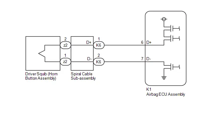 w/ Occupant Classification System

CAUTION / NOTICE / HINT
NOTICE:
-
After the ignition switch is turned off, there may be a waiting time before disconnecting the negative (-) auxiliary battery terminal.
Click here

HINT:
When disconnecting and reconnecting the auxiliary battery, there is an automatic learning function that completes learning when the respective system is used.
Click here


-
After replacing the airbag ECU assembly, refer to work procedure.
Click here


-
When installing the spiral cable sub-assembly and steering wheel, be sure to adjust the spiral cable sub-assembly as it may break if the steering wheel is turned before adjusting the spiral cable sub-assembly.
Click here


HINT:
-
To perform the simulation method, enter check mode (signal check) with the GTS.
Click here

-
Perform the simulation method while checking the Data List.
Click here

PROCEDURE
| 1. | CLEAR DTC |
Pre-procedure1
(a) Turn the ignition switch to ON, and wait for at least 60 seconds.
Procedure1
(b) Clear the DTCs stored in memory.
Body Electrical > SRS Airbag > Clear DTCsPost-procedure1
(c) Turn the ignition switch off.
|

| 2. | CHECK DTC |
Pre-procedure1
(a) Turn the ignition switch to ON, and wait for at least 60 seconds.
Procedure1
(b) Check for DTCs.
Body Electrical > SRS Airbag > Trouble Codes| Result | Proceed to |
|---|---|
| B000111 is output | A |
| B000111 is not output | B |
Post-procedure1
(c) None
| B |

| USE SIMULATION METHOD TO CHECK |
|

| 3. | CHECK CONNECTION OF CONNECTORS |
Pre-procedure1
(a) Turn the ignition switch off.
(b) Disconnect the cable from the negative (-) auxiliary battery terminal, and wait for at least 60 seconds.
Procedure1
(c) Check that the connectors are properly connected to the horn button assembly, spiral cable sub-assembly and airbag ECU assembly.
OK:
The connectors are properly connected.
Post-procedure1
(d) None
| NG |

| CONNECT CONNECTORS PROPERLY |
|

| 4. | CHECK CONNECTORS |
Pre-procedure1
| (a) Disconnect the airbag ECU assembly connector. |
|

(b) Disconnect the spiral cable sub-assembly connector.
(c) Disconnect the horn button assembly connector.
Procedure1
(d) Check that the terminals of the connectors are not deformed or damaged.
OK:
The terminals are not deformed or damaged.
(e) Check that the connectors are not loose, deformed or damaged.
OK:
The connector locking button is not disengaged, and the claw of the lock is not deformed or damaged.
(f) Check that the short springs of the activation prevention mechanisms of the wire harness connector and spiral cable sub-assembly connector are not deformed or damaged.
OK:
The short springs are not deformed or damaged.
Post-procedure1
(g) None
| NG |

| REPAIR OR REPLACE WIRE HARNESS OR SPIRAL CABLE SUB-ASSEMBLY |
|

| 5. | CHECK Toyota Prius Vehicle CONDITION |
(a) Choose the model to be inspected.
| Result | Proceed to |
|---|---|
| w/o Occupant Classification System | A |
| w/ Occupant Classification System | B |
| B |

| GO TO STEP 12 |
|

| 6. | CLEAR DTC |
Pre-procedure1
| (a) Connect the airbag ECU assembly connector. |
|

(b) Connect the spiral cable sub-assembly connector.
(c) Connect SST (resistance: 2.1 Ω) to connector E.
CAUTION:
Never connect the tester to the horn button assembly for measurement, as this may lead to a serious injury due to airbag deployment.
NOTICE:
- Do not forcibly insert SST into the terminals of the connector when connecting SST.
- Insert SST straight into the terminals of the connector.
SST: 09843-18061
(d) Connect the cable to the negative (-) auxiliary battery terminal, and wait for at least 2 seconds.
(e) Turn the ignition switch to ON, and wait for at least 60 seconds.
Procedure1
(f) Clear the DTCs stored in memory.
Body Electrical > SRS Airbag > Clear DTCsPost-procedure1
(g) Turn the ignition switch off.
|

| 7. | CHECK HORN BUTTON ASSEMBLY |
Pre-procedure1
(a) Turn the ignition switch to ON, and wait for at least 60 seconds.
Procedure1
(b) Check for DTCs.
Body Electrical > SRS Airbag > Trouble Codes| Result | Proceed to |
|---|---|
| B000111 is not output | A |
| B000111 is output | B |
HINT:
Codes other than DTC B000111 may be output at this time, but they are not related to this check.
Post-procedure1
(c) Turn the ignition switch off.
(d) Disconnect the cable from the negative (-) auxiliary battery terminal, and wait for at least 60 seconds.
(e) Disconnect SST from connector E.
| A |

| REPLACE HORN BUTTON ASSEMBLY
|


|

| 8. | CHECK DRIVER SIDE SQUIB CIRCUIT |
Pre-procedure1
(a) Disconnect the airbag ECU assembly connector.
Procedure1
| (b) Measure the resistance according to the value(s) in the table below. Standard Resistance:  Click Location & Routing(z2) Click Connector(z2) Click Location & Routing(z2) Click Connector(z2)
Result:
|
|
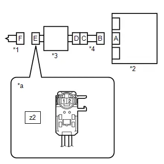
Post-procedure1
(c) None
| NG |

| GO TO STEP 11 |
|

| 9. | CLEAR DTC |
Pre-procedure1
| (a) Connect the airbag ECU assembly connector. |
|
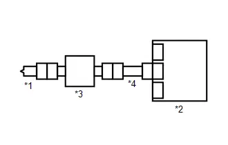
(b) Connect the horn button assembly connector.
(c) Connect the cable to the negative (-) auxiliary battery terminal, and wait for at least 2 seconds.
(d) Turn the ignition switch to ON, and wait for at least 60 seconds.
Procedure1
(e) Clear the DTCs stored in memory.
Body Electrical > SRS Airbag > Clear DTCsPost-procedure1
(f) Turn the ignition switch off.
|

| 10. | CHECK DTC |
Pre-procedure1
(a) Turn the ignition switch to ON, and wait for at least 60 seconds.
Procedure1
(b) Check for DTCs.
Body Electrical > SRS Airbag > Trouble Codes| Result | Proceed to |
|---|---|
| B000111 is not output | A |
| B000111 is output | B |
HINT:
Codes other than DTC B000111 may be output at this time, but they are not related to this check.
Post-procedure1
(c) None
| A |

| USE SIMULATION METHOD TO CHECK |
| B |

| REPLACE AIRBAG ECU ASSEMBLY
|


| 11. | CHECK HARNESS AND CONNECTOR |
Pre-procedure1
(a) Disconnect the spiral cable sub-assembly connector.
Procedure1
| (b) Measure the resistance according to the value(s) in the table below. Standard Resistance:  Click Location & Routing(K6) Click Connector(K6) Click Location & Routing(K6) Click Connector(K6)
Result:
|
|
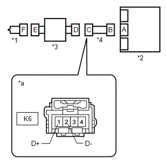
Post-procedure1
(c) None
| OK |

| REPLACE SPIRAL CABLE SUB-ASSEMBLY
|


| NG |

| REPAIR OR REPLACE HARNESS OR CONNECTOR |
| 12. | CLEAR DTC |
Pre-procedure1
| (a) Connect the airbag ECU assembly connector. |
|
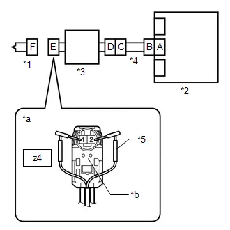
(b) Connect the spiral cable sub-assembly connector.
(c) Connect SST (resistance: 2.1 Ω) to connector E (light green connector).
CAUTION:
Never connect the tester to the horn button assembly for measurement, as this may lead to a serious injury due to airbag deployment.
NOTICE:
- Do not forcibly insert SST into the terminals of the connector when connecting SST.
- Insert SST straight into the terminals of the connector.
SST: 09843-18061
(d) Connect the cable to the negative (-) auxiliary battery terminal, and wait for at least 2 seconds.
(e) Turn the ignition switch to ON, and wait for at least 60 seconds.
Procedure1
(f) Clear the DTCs stored in memory.
Body Electrical > SRS Airbag > Clear DTCsPost-procedure1
(g) Turn the ignition switch off.
|

| 13. | CHECK HORN BUTTON ASSEMBLY |
Pre-procedure1
(a) Turn the ignition switch to ON, and wait for at least 60 seconds.
Procedure1
(b) Check for DTCs.
Body Electrical > SRS Airbag > Trouble Codes| Result | Proceed to |
|---|---|
| B000111 is not output | A |
| B000111 is output | B |
HINT:
Codes other than DTC B000111 may be output at this time, but they are not related to this check.
Post-procedure1
(c) Turn the ignition switch off.
(d) Disconnect the cable from the negative (-) auxiliary battery terminal, and wait for at least 60 seconds.
(e) Disconnect SST from connector E.
| A |

| REPLACE HORN BUTTON ASSEMBLY
|


|

| 14. | CHECK DRIVER SIDE SQUIB CIRCUIT |
Pre-procedure1
(a) Disconnect the airbag ECU assembly connector.
Procedure1
| (b) Measure the resistance according to the value(s) in the table below. Standard Resistance:  Click Location & Routing(z4) Click Connector(z4) Click Location & Routing(z4) Click Connector(z4)
Result:
|
|
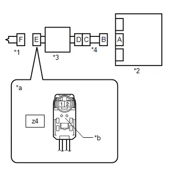
Post-procedure1
(c) None
| NG |

| GO TO STEP 17 |
|

| 15. | CLEAR DTC |
Pre-procedure1
| (a) Connect the airbag ECU assembly connector. |
|

(b) Connect the horn button assembly connector.
(c) Connect the cable to the negative (-) auxiliary battery terminal, and wait for at least 2 seconds.
(d) Turn the ignition switch to ON, and wait for at least 60 seconds.
Procedure1
(e) Clear the DTCs stored in memory.
Body Electrical > SRS Airbag > Clear DTCsPost-procedure1
(f) Turn the ignition switch off.
|

| 16. | CHECK DTC |
Pre-procedure1
(a) Turn the ignition switch to ON, and wait for at least 60 seconds.
Procedure1
(b) Check for DTCs.
Body Electrical > SRS Airbag > Trouble Codes| Result | Proceed to |
|---|---|
| B000111 is not output | A |
| B000111 is output | B |
HINT:
Codes other than DTC B000111 may be output at this time, but they are not related to this check.
Post-procedure1
(c) None
| A |

| USE SIMULATION METHOD TO CHECK |
| B |

| REPLACE AIRBAG ECU ASSEMBLY
|


| 17. | CHECK HARNESS AND CONNECTOR |
Pre-procedure1
(a) Disconnect the spiral cable sub-assembly connector.
Procedure1
| (b) Measure the resistance according to the value(s) in the table below. Standard Resistance:  Click Location & Routing(K6) Click Connector(K6) Click Location & Routing(K6) Click Connector(K6)
Result:
|
|

Post-procedure1
(c) None
| OK |

| REPLACE SPIRAL CABLE SUB-ASSEMBLY
|


| NG |

| REPAIR OR REPLACE HARNESS OR CONNECTOR |
Driver Frontal Stage 2 Deployment Control Circuit Short to Ground (B000211)
DESCRIPTION
| DTC No. | Detection Item | DTC Detection Condition | Trouble Area | Warning Indicate | DTC Output from | Priority | Test Mode / Check Mode |
|---|---|---|---|---|---|---|---|
| B000211 | Driver Frontal Stage 2 Deployment Control Circuit Short to Ground |
|
| Comes on | SRS Airbag | A | Applies to check mode |
WIRING DIAGRAM

CAUTION / NOTICE / HINT
NOTICE:
-
After the ignition switch is turned off, there may be a waiting time before disconnecting the negative (-) auxiliary battery terminal.
Click here

HINT:
When disconnecting and reconnecting the auxiliary battery, there is an automatic learning function that completes learning when the respective system is used.
Click here


-
After replacing the airbag ECU assembly, refer to work procedure.
Click here


-
When installing the spiral cable sub-assembly and steering wheel, be sure to adjust the spiral cable sub-assembly as it may break if the steering wheel is turned before adjusting the spiral cable sub-assembly.
Click here


HINT:
-
To perform the simulation method, enter check mode (signal check) with the GTS.
Click here

-
Perform the simulation method while checking the Data List.
Click here

PROCEDURE
| 1. | CLEAR DTC |
Pre-procedure1
(a) Turn the ignition switch to ON, and wait for at least 60 seconds.
Procedure1
(b) Clear the DTCs stored in memory.
Body Electrical > SRS Airbag > Clear DTCsPost-procedure1
(c) Turn the ignition switch off.
|

| 2. | CHECK DTC |
Pre-procedure1
(a) Turn the ignition switch to ON, and wait for at least 60 seconds.
Procedure1
(b) Check for DTCs.
Body Electrical > SRS Airbag > Trouble Codes| Result | Proceed to |
|---|---|
| B000211 is output | A |
| B000211 is not output | B |
Post-procedure1
(c) None
| B |

| USE SIMULATION METHOD TO CHECK |
|

| 3. | CHECK CONNECTION OF CONNECTORS |
Pre-procedure1
(a) Turn the ignition switch off.
(b) Disconnect the cable from the negative (-) auxiliary battery terminal, and wait for at least 60 seconds.
Procedure1
(c) Check that the connectors are properly connected to the horn button assembly, spiral cable sub-assembly and airbag ECU assembly.
OK:
The connectors are properly connected.
Post-procedure1
(d) None
| NG |

| CONNECT CONNECTORS PROPERLY |
|

| 4. | CHECK CONNECTORS |
Pre-procedure1
| (a) Disconnect the airbag ECU assembly connector. |
|
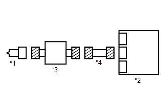
(b) Disconnect the spiral cable sub-assembly connector.
(c) Disconnect the horn button assembly connector.
Procedure1
(d) Check that the terminals of the connectors are not deformed or damaged.
OK:
The terminals are not deformed or damaged.
(e) Check that the connectors are not loose, deformed or damaged.
OK:
The connector locking button is not disengaged, and the claw of the lock is not deformed or damaged.
(f) Check that the short springs of the activation prevention mechanisms of the spiral cable sub-assembly connector are not deformed or damaged.
OK:
The short springs are not deformed or damaged.
Post-procedure1
(g) None
| NG |

| REPAIR OR REPLACE WIRE HARNESS OR SPIRAL CABLE SUB-ASSEMBLY |
|

| 5. | CLEAR DTC |
Pre-procedure1
| (a) Connect the airbag ECU assembly connector. |
|

(b) Connect the spiral cable sub-assembly connector.
(c) Connect SST (resistance: 2.1 Ω) to connector E (black connector).
CAUTION:
Never connect the tester to the horn button assembly for measurement, as this may lead to a serious injury due to airbag deployment.
NOTICE:
- Do not forcibly insert SST into the terminals of the connector when connecting SST.
- Insert SST straight into the terminals of the connector.
SST: 09843-18061
(d) Connect the cable to the negative (-) auxiliary battery terminal, and wait for at least 2 seconds.
(e) Turn the ignition switch to ON, and wait for at least 60 seconds.
Procedure1
(f) Clear the DTCs stored in memory.
Body Electrical > SRS Airbag > Clear DTCsPost-procedure1
(g) Turn the ignition switch off.
|

| 6. | CHECK HORN BUTTON ASSEMBLY |
Pre-procedure1
(a) Turn the ignition switch to ON, and wait for at least 60 seconds.
Procedure1
(b) Check for DTCs.
Body Electrical > SRS Airbag > Trouble Codes| Result | Proceed to |
|---|---|
| B000211 is not output | A |
| B000211 is output | B |
HINT:
Codes other than DTC B000211 may be output at this time, but they are not related to this check.
Post-procedure1
(c) Turn the ignition switch off.
(d) Disconnect the cable from the negative (-) auxiliary battery terminal, and wait for at least 60 seconds.
(e) Disconnect SST from connector E.
| A |

| REPLACE HORN BUTTON ASSEMBLY
|


|

| 7. | CHECK DRIVER SIDE 2ND SQUIB CIRCUIT |
Pre-procedure1
(a) Disconnect the airbag ECU assembly connector.
Procedure1
| (b) Measure the resistance according to the value(s) in the table below. Standard Resistance:  Click Location & Routing(z3) Click Connector(z3) Click Location & Routing(z3) Click Connector(z3)
Result:
|
|

Post-procedure1
(c) None
| NG |

| GO TO STEP 10 |
|

| 8. | CLEAR DTC |
Pre-procedure1
| (a) Connect the airbag ECU assembly connector. |
|

(b) Connect the horn button assembly connector.
(c) Connect the cable to the negative (-) auxiliary battery terminal, and wait for at least 2 seconds.
(d) Turn the ignition switch to ON, and wait for at least 60 seconds.
Procedure1
(e) Clear the DTCs stored in memory.
Body Electrical > SRS Airbag > Clear DTCsPost-procedure1
(f) Turn the ignition switch off.
|

| 9. | CHECK DTC |
Pre-procedure1
(a) Turn the ignition switch to ON, and wait for at least 60 seconds.
Procedure1
(b) Check for DTCs.
Body Electrical > SRS Airbag > Trouble Codes| Result | Proceed to |
|---|---|
| B000211 is not output | A |
| B000211 is output | B |
HINT:
Codes other than DTC B000211 may be output at this time, but they are not related to this check.
Post-procedure1
(c) None
| A |

| USE SIMULATION METHOD TO CHECK |
| B |

| REPLACE AIRBAG ECU ASSEMBLY
|


| 10. | CHECK HARNESS AND CONNECTOR |
Pre-procedure1
(a) Disconnect the spiral cable sub-assembly connector.
Procedure1
| (b) Measure the resistance according to the value(s) in the table below. Standard Resistance:  Click Location & Routing(K6) Click Connector(K6) Click Location & Routing(K6) Click Connector(K6)
Result:
|
|
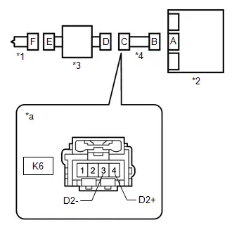
Post-procedure1
(c) None
| OK |

| REPLACE SPIRAL CABLE SUB-ASSEMBLY
|


| NG |

| REPAIR OR REPLACE HARNESS OR CONNECTOR |
Driver Knee Bolster Deployment Control Circuit Short to Ground (B000411)
DESCRIPTION
| DTC No. | Detection Item | DTC Detection Condition | Trouble Area | Warning Indicate | DTC Output from | Priority | Test Mode / Check Mode |
|---|---|---|---|---|---|---|---|
| B000411 | Driver Knee Bolster Deployment Control Circuit Short to Ground |
|
| Comes on | SRS Airbag | A | Applies to check mode |
WIRING DIAGRAM

CAUTION / NOTICE / HINT
NOTICE:
-
After the ignition switch is turned off, there may be a waiting time before disconnecting the negative (-) auxiliary battery terminal.
Click here

HINT:
When disconnecting and reconnecting the auxiliary battery, there is an automatic learning function that completes learning when the respective system is used.
Click here


-
After replacing the airbag ECU assembly, refer to work procedure.
Click here


HINT:
-
To perform the simulation method, enter check mode (signal check) with the GTS.
Click here

-
Perform the simulation method while checking the Data List.
Click here

PROCEDURE
| 1. | CLEAR DTC |
Pre-procedure1
(a) Turn the ignition switch to ON, and wait for at least 60 seconds.
Procedure1
(b) Clear the DTCs stored in memory.
Body Electrical > SRS Airbag > Clear DTCsPost-procedure1
(c) Turn the ignition switch off.
|

| 2. | CHECK DTC |
Pre-procedure1
(a) Turn the ignition switch to ON, and wait for at least 60 seconds.
Procedure1
(b) Check for DTCs.
Body Electrical > SRS Airbag > Trouble Codes| Result | Proceed to |
|---|---|
| B000411 is output | A |
| B000411 is not output | B |
Post-procedure1
(c) None
| B |

| USE SIMULATION METHOD TO CHECK |
|

| 3. | CHECK CONNECTION OF CONNECTORS |
Pre-procedure1
(a) Turn the ignition switch off.
(b) Disconnect the cable from the negative (-) auxiliary battery terminal, and wait for at least 60 seconds.
Procedure1
(c) Check that the connectors are properly connected to the lower No. 1 instrument panel airbag assembly and airbag ECU assembly.
OK:
The connectors are properly connected.
Post-procedure1
(d) None
| NG |

| CONNECT CONNECTORS PROPERLY |
|

| 4. | CHECK CONNECTORS |
Pre-procedure1
| (a) Disconnect the airbag ECU assembly connector. |
|

(b) Disconnect the lower No. 1 instrument panel airbag assembly connector.
Procedure1
(c) Check that the terminals of the connectors are not deformed or damaged.
OK:
The terminals are not deformed or damaged.
(d) Check that the connectors are not loose, deformed or damaged.
OK:
The connector locking button is not disengaged, and the claw of the lock is not deformed or damaged.
Post-procedure1
(e) None
| NG |

| REPAIR OR REPLACE HARNESS OR CONNECTOR |
|

| 5. | CLEAR DTC |
Pre-procedure1
| (a) Connect the airbag ECU assembly connector. |
|

(b) Connect SST (resistance: 2.1 Ω) to connector C.
CAUTION:
Never connect the tester to the lower No. 1 instrument panel airbag assembly for measurement, as this may lead to a serious injury due to airbag deployment.
NOTICE:
- Do not forcibly insert SST into the terminals of the connector when connecting SST.
- Insert SST straight into the terminals of the connector.
SST: 09843-18061
(c) Connect the cable to the negative (-) auxiliary battery terminal, and wait for at least 2 seconds.
(d) Turn the ignition switch to ON, and wait for at least 60 seconds.
Procedure1
(e) Clear the DTCs stored in memory.
Body Electrical > SRS Airbag > Clear DTCsPost-procedure1
(f) Turn the ignition switch off.
|

| 6. | CHECK LOWER NO. 1 INSTRUMENT PANEL AIRBAG ASSEMBLY |
Pre-procedure1
(a) Turn the ignition switch to ON, and wait for at least 60 seconds.
Procedure1
(b) Check for DTCs.
Body Electrical > SRS Airbag > Trouble Codes| Result | Proceed to |
|---|---|
| B000411 is not output | A |
| B000411 is output | B |
HINT:
Codes other than DTC B000411 may be output at this time, but they are not related to this check.
Post-procedure1
(c) Turn the ignition switch off.
(d) Disconnect the cable from the negative (-) auxiliary battery terminal, and wait for at least 60 seconds.
(e) Disconnect SST from connector C.
| A |

| REPLACE LOWER NO. 1 INSTRUMENT PANEL AIRBAG ASSEMBLY
|


|

| 7. | CHECK HARNESS AND CONNECTOR |
Pre-procedure1
(a) Disconnect the airbag ECU assembly connector.
Procedure1
| (b) Measure the resistance according to the value(s) in the table below. Standard Resistance:  Click Location & Routing(K7) Click Connector(K7) Click Location & Routing(K7) Click Connector(K7)
Result:
|
|
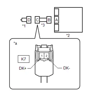
Post-procedure1
(c) None
| NG |

| REPAIR OR REPLACE HARNESS OR CONNECTOR |
|

| 8. | CLEAR DTC |
Pre-procedure1
| (a) Connect the airbag ECU assembly connector. |
|
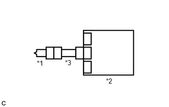
(b) Connect the lower No. 1 instrument panel airbag assembly connector.
(c) Connect the cable to the negative (-) auxiliary battery terminal, and wait for at least 2 seconds.
(d) Turn the ignition switch to ON, and wait for at least 60 seconds.
Procedure1
(e) Clear the DTCs stored in memory.
Body Electrical > SRS Airbag > Clear DTCsPost-procedure1
(f) Turn the ignition switch off.
|

| 9. | CHECK DTC |
Pre-procedure1
(a) Turn the ignition switch to ON, and wait for at least 60 seconds.
Procedure1
(b) Check for DTCs.
Body Electrical > SRS Airbag > Trouble Codes| Result | Proceed to |
|---|---|
| B000411 is not output | A |
| B000411 is output | B |
HINT:
Codes other than DTC B000411 may be output at this time, but they are not related to this check.
Post-procedure1
(c) None
| A |

| USE SIMULATION METHOD TO CHECK |
| B |

| REPLACE AIRBAG ECU ASSEMBLY
|


Driver Knee Bolster Deployment Control Circuit Short to Battery (B000412)
DESCRIPTION
| DTC No. | Detection Item | DTC Detection Condition | Trouble Area | Warning Indicate | DTC Output from | Priority | Test Mode / Check Mode |
|---|---|---|---|---|---|---|---|
| B000412 | Driver Knee Bolster Deployment Control Circuit Short to Battery |
|
| Comes on | SRS Airbag | A | Applies to check mode |
WIRING DIAGRAM
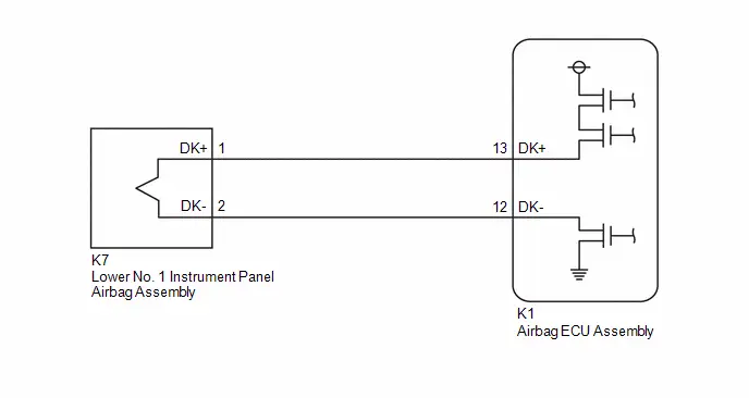
CAUTION / NOTICE / HINT
NOTICE:
-
After the ignition switch is turned off, there may be a waiting time before disconnecting the negative (-) auxiliary battery terminal.
Click here

HINT:
When disconnecting and reconnecting the auxiliary battery, there is an automatic learning function that completes learning when the respective system is used.
Click here


-
After replacing the airbag ECU assembly, refer to work procedure.
Click here


HINT:
-
To perform the simulation method, enter check mode (signal check) with the GTS.
Click here

-
Perform the simulation method while checking the Data List.
Click here

PROCEDURE
| 1. | CLEAR DTC |
Pre-procedure1
(a) Turn the ignition switch to ON, and wait for at least 60 seconds.
Procedure1
(b) Clear the DTCs stored in memory.
Body Electrical > SRS Airbag > Clear DTCsPost-procedure1
(c) Turn the ignition switch off.
|

| 2. | CHECK DTC |
Pre-procedure1
(a) Turn the ignition switch to ON, and wait for at least 60 seconds.
Procedure1
(b) Check for DTCs.
Body Electrical > SRS Airbag > Trouble Codes| Result | Proceed to |
|---|---|
| B000412 is output | A |
| B000412 is not output | B |
Post-procedure1
(c) None
| B |

| USE SIMULATION METHOD TO CHECK |
|

| 3. | CHECK CONNECTION OF CONNECTORS |
Pre-procedure1
(a) Turn the ignition switch off.
(b) Disconnect the cable from the negative (-) auxiliary battery terminal, and wait for at least 60 seconds.
Procedure1
(c) Check that the connectors are properly connected to the lower No. 1 instrument panel airbag assembly and airbag ECU assembly.
OK:
The connectors are properly connected.
Post-procedure1
(d) None
| NG |

| CONNECT CONNECTORS PROPERLY |
|

| 4. | CHECK CONNECTORS |
Pre-procedure1
| (a) Disconnect the airbag ECU assembly connector. |
|

(b) Disconnect the lower No. 1 instrument panel airbag assembly connector.
Procedure1
(c) Check that the terminals of the connectors are not deformed or damaged.
OK:
The terminals are not deformed or damaged.
(d) Check that the connectors are not loose, deformed or damaged.
OK:
The connector locking button is not disengaged, and the claw of the lock is not deformed or damaged.
Post-procedure1
(e) None
| NG |

| REPAIR OR REPLACE HARNESS OR CONNECTOR |
|

| 5. | CLEAR DTC |
Pre-procedure1
| (a) Connect the airbag ECU assembly connector. |
|

(b) Connect SST (resistance: 2.1 Ω) to connector C.
CAUTION:
Never connect the tester to the lower No. 1 instrument panel airbag assembly for measurement, as this may lead to a serious injury due to airbag deployment.
NOTICE:
- Do not forcibly insert SST into the terminals of the connector when connecting SST.
- Insert SST straight into the terminals of the connector.
SST: 09843-18061
(c) Connect the cable to the negative (-) auxiliary battery terminal, and wait for at least 2 seconds.
(d) Turn the ignition switch to ON, and wait for at least 60 seconds.
Procedure1
(e) Clear the DTCs stored in memory.
Body Electrical > SRS Airbag > Clear DTCsPost-procedure1
(f) Turn the ignition switch off.
|

| 6. | CHECK LOWER NO. 1 INSTRUMENT PANEL AIRBAG ASSEMBLY |
Pre-procedure1
(a) Turn the ignition switch to ON, and wait for at least 60 seconds.
Procedure1
(b) Check for DTCs.
Body Electrical > SRS Airbag > Trouble Codes| Result | Proceed to |
|---|---|
| B000412 is not output | A |
| B000412 is output | B |
HINT:
Codes other than DTC B000412 may be output at this time, but they are not related to this check.
Post-procedure1
(c) Turn the ignition switch off.
(d) Disconnect the cable from the negative (-) auxiliary battery terminal, and wait for at least 60 seconds.
(e) Disconnect SST from connector C.
| A |

| REPLACE LOWER NO. 1 INSTRUMENT PANEL AIRBAG ASSEMBLY
|


|

| 7. | CHECK HARNESS AND CONNECTOR |
Pre-procedure1
(a) Disconnect the airbag ECU assembly connector.
(b) Connect the cable to the negative (-) auxiliary battery terminal, and wait for at least 2 seconds.
(c) Turn the ignition switch to ON.
Procedure1
| (d) Measure the voltage according to the value(s) in the table below. Standard Voltage:  Click Location & Routing(K7) Click Connector(K7) Click Location & Routing(K7) Click Connector(K7)
Result:
|
|

Post-procedure1
(e) Turn the ignition switch off.
(f) Disconnect the cable from the negative (-) auxiliary battery terminal, and wait for at least 60 seconds.
| NG |

| REPAIR OR REPLACE HARNESS OR CONNECTOR |
|

| 8. | CLEAR DTC |
Pre-procedure1
| (a) Connect the airbag ECU assembly connector. |
|

(b) Connect the lower No. 1 instrument panel airbag assembly connector.
(c) Connect the cable to the negative (-) auxiliary battery terminal, and wait for at least 2 seconds.
(d) Turn the ignition switch to ON, and wait for at least 60 seconds.
Procedure1
(e) Clear the DTCs stored in memory.
Body Electrical > SRS Airbag > Clear DTCsPost-procedure1
(f) Turn the ignition switch off.
|

| 9. | CHECK DTC |
Pre-procedure1
(a) Turn the ignition switch to ON, and wait for at least 60 seconds.
Procedure1
(b) Check for DTCs.
Body Electrical > SRS Airbag > Trouble Codes| Result | Proceed to |
|---|---|
| B000412 is not output | A |
| B000412 is output | B |
HINT:
Codes other than DTC B000412 may be output at this time, but they are not related to this check.
Post-procedure1
(c) None
| A |

| USE SIMULATION METHOD TO CHECK |
| B |

| REPLACE AIRBAG ECU ASSEMBLY
|


Driver Knee Bolster Deployment Control Circuit Open (B000413)
DESCRIPTION
| DTC No. | Detection Item | DTC Detection Condition | Trouble Area | Warning Indicate | DTC Output from | Priority | Test Mode / Check Mode |
|---|---|---|---|---|---|---|---|
| B000413 | Driver Knee Bolster Deployment Control Circuit Open |
|
| Comes on | SRS Airbag | A | Applies to check mode |
WIRING DIAGRAM

CAUTION / NOTICE / HINT
NOTICE:
-
After the ignition switch is turned off, there may be a waiting time before disconnecting the negative (-) auxiliary battery terminal.
Click here

HINT:
When disconnecting and reconnecting the auxiliary battery, there is an automatic learning function that completes learning when the respective system is used.
Click here


-
After replacing the airbag ECU assembly, refer to work procedure.
Click here


HINT:
-
To perform the simulation method, enter check mode (signal check) with the GTS.
Click here

-
Perform the simulation method while checking the Data List.
Click here

PROCEDURE
| 1. | CLEAR DTC |
Pre-procedure1
(a) Turn the ignition switch to ON, and wait for at least 60 seconds.
Procedure1
(b) Clear the DTCs stored in memory.
Body Electrical > SRS Airbag > Clear DTCsPost-procedure1
(c) Turn the ignition switch off.
|

| 2. | CHECK DTC |
Pre-procedure1
(a) Turn the ignition switch to ON, and wait for at least 60 seconds.
Procedure1
(b) Check for DTCs.
Body Electrical > SRS Airbag > Trouble Codes| Result | Proceed to |
|---|---|
| B000413 is output | A |
| B000413 is not output | B |
Post-procedure1
(c) None
| B |

| USE SIMULATION METHOD TO CHECK |
|

| 3. | CHECK CONNECTION OF CONNECTORS |
Pre-procedure1
(a) Turn the ignition switch off.
(b) Disconnect the cable from the negative (-) auxiliary battery terminal, and wait for at least 60 seconds.
Procedure1
(c) Check that the connectors are properly connected to the lower No. 1 instrument panel airbag assembly and airbag ECU assembly.
OK:
The connectors are properly connected.
Post-procedure1
(d) None
| NG |

| CONNECT CONNECTORS PROPERLY |
|

| 4. | CHECK CONNECTORS |
Pre-procedure1
| (a) Disconnect the airbag ECU assembly connector. |
|

(b) Disconnect the lower No. 1 instrument panel airbag assembly connector.
Procedure1
(c) Check that the terminals of the connectors are not deformed or damaged.
OK:
The terminals are not deformed or damaged.
(d) Check that the connectors are not loose, deformed or damaged.
OK:
The connector locking button is not disengaged, and the claw of the lock is not deformed or damaged.
Post-procedure1
(e) None
| NG |

| REPAIR OR REPLACE HARNESS OR CONNECTOR |
|

| 5. | CLEAR DTC |
Pre-procedure1
| (a) Connect the airbag ECU assembly connector. |
|
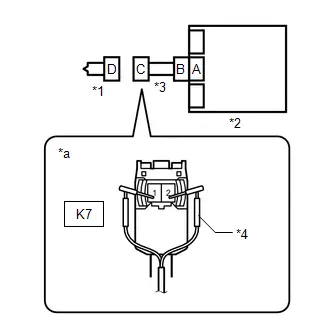
(b) Connect SST (resistance: 2.1 Ω) to connector C.
CAUTION:
Never connect the tester to the lower No. 1 instrument panel airbag assembly for measurement, as this may lead to a serious injury due to airbag deployment.
NOTICE:
- Do not forcibly insert SST into the terminals of the connector when connecting SST.
- Insert SST straight into the terminals of the connector.
SST: 09843-18061
(c) Connect the cable to the negative (-) auxiliary battery terminal, and wait for at least 2 seconds.
(d) Turn the ignition switch to ON, and wait for at least 60 seconds.
Procedure1
(e) Clear the DTCs stored in memory.
Body Electrical > SRS Airbag > Clear DTCsPost-procedure1
(f) Turn the ignition switch off.
|

| 6. | CHECK LOWER NO. 1 INSTRUMENT PANEL AIRBAG ASSEMBLY |
Pre-procedure1
(a) Turn the ignition switch to ON, and wait for at least 60 seconds.
Procedure1
(b) Check for DTCs.
Body Electrical > SRS Airbag > Trouble Codes| Result | Proceed to |
|---|---|
| B000413 is not output | A |
| B000413 is output | B |
HINT:
Codes other than DTC B000413 may be output at this time, but they are not related to this check.
Post-procedure1
(c) Turn the ignition switch off.
(d) Disconnect the cable from the negative (-) auxiliary battery terminal, and wait for at least 60 seconds.
(e) Disconnect SST from connector C.
| A |

| REPLACE LOWER NO. 1 INSTRUMENT PANEL AIRBAG ASSEMBLY
|


|

| 7. | CHECK HARNESS AND CONNECTOR |
Pre-procedure1
| (a) Disconnect the airbag ECU assembly connector. |
|
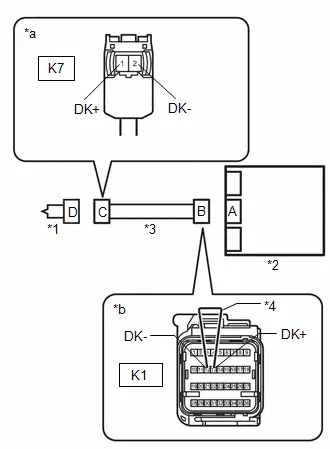
(b) Using a service wire, connect terminals 13 (DK ) and 12 (DK-) of connector B.
NOTICE:
Do not forcibly insert the service wire into the terminals of the connector when connecting a service wire.
Procedure1
(c) Measure the resistance according to the value(s) in the table below.
Standard Resistance:
 Click Location & Routing(K7) Click Connector(K7)
 | Tester Connection | Condition | Specified Condition | Result |
|---|---|---|---|
| K7-1 (DK ) - K7-2 (DK-) | Always | Below 1 Ω | Ω |
Post-procedure1
(d) Disconnect the service wire from connector B.
| NG |

| REPAIR OR REPLACE HARNESS OR CONNECTOR |
|

| 8. | CLEAR DTC |
Pre-procedure1
| (a) Connect the airbag ECU assembly connector. |
|

(b) Connect the lower No. 1 instrument panel airbag assembly connector.
(c) Connect the cable to the negative (-) auxiliary battery terminal, and wait for at least 2 seconds.
(d) Turn the ignition switch to ON, and wait for at least 60 seconds.
Procedure1
(e) Clear the DTCs stored in memory.
Body Electrical > SRS Airbag > Clear DTCsPost-procedure1
(f) Turn the ignition switch off.
|

| 9. | CHECK DTC |
Pre-procedure1
(a) Turn the ignition switch to ON, and wait for at least 60 seconds.
Procedure1
(b) Check for DTCs.
Body Electrical > SRS Airbag > Trouble Codes| Result | Proceed to |
|---|---|
| B000413 is not output | A |
| B000413 is output | B |
HINT:
Codes other than DTC B000413 may be output at this time, but they are not related to this check.
Post-procedure1
(c) None
| A |

| USE SIMULATION METHOD TO CHECK |
| B |

| REPLACE AIRBAG ECU ASSEMBLY
|


Driver Knee Bolster Deployment Control Circuit Resistance Below Threshold (B00041A)
DESCRIPTION
| DTC No. | Detection Item | DTC Detection Condition | Trouble Area | Warning Indicate | DTC Output from | Priority | Test Mode / Check Mode |
|---|---|---|---|---|---|---|---|
| B00041A | Driver Knee Bolster Deployment Control Circuit Resistance Below Threshold |
|
| Comes on | SRS Airbag | A | Applies to check mode |
WIRING DIAGRAM

CAUTION / NOTICE / HINT
NOTICE:
-
After the ignition switch is turned off, there may be a waiting time before disconnecting the negative (-) auxiliary battery terminal.
Click here

HINT:
When disconnecting and reconnecting the auxiliary battery, there is an automatic learning function that completes learning when the respective system is used.
Click here


-
After replacing the airbag ECU assembly, refer to work procedure.
Click here


HINT:
-
To perform the simulation method, enter check mode (signal check) with the GTS.
Click here

-
Perform the simulation method while checking the Data List.
Click here

PROCEDURE
| 1. | CLEAR DTC |
Pre-procedure1
(a) Turn the ignition switch to ON, and wait for at least 60 seconds.
Procedure1
(b) Clear the DTCs stored in memory.
Body Electrical > SRS Airbag > Clear DTCsPost-procedure1
(c) Turn the ignition switch off.
|

| 2. | CHECK DTC |
Pre-procedure1
(a) Turn the ignition switch to ON, and wait for at least 60 seconds.
Procedure1
(b) Check for DTCs.
Body Electrical > SRS Airbag > Trouble Codes| Result | Proceed to |
|---|---|
| B00041A is output | A |
| B00041A is not output | B |
Post-procedure1
(c) None
| B |

| USE SIMULATION METHOD TO CHECK |
|

| 3. | CHECK CONNECTION OF CONNECTORS |
Pre-procedure1
(a) Turn the ignition switch off.
(b) Disconnect the cable from the negative (-) auxiliary battery terminal, and wait for at least 60 seconds.
Procedure1
(c) Check that the connectors are properly connected to the lower No. 1 instrument panel airbag assembly and airbag ECU assembly.
OK:
The connectors are properly connected.
Post-procedure1
(d) None
| NG |

| CONNECT CONNECTORS PROPERLY |
|

| 4. | CHECK CONNECTORS |
Pre-procedure1
| (a) Disconnect the airbag ECU assembly connector. |
|
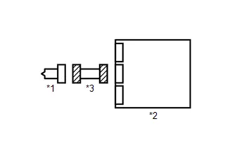
(b) Disconnect the lower No. 1 instrument panel airbag assembly connector.
Procedure1
(c) Check that the terminals of the connectors are not deformed or damaged.
OK:
The terminals are not deformed or damaged.
(d) Check that the connectors are not loose, deformed or damaged.
OK:
The connector locking button is not disengaged, and the claw of the lock is not deformed or damaged.
Post-procedure1
(e) None
| NG |

| REPAIR OR REPLACE HARNESS OR CONNECTOR |
|

| 5. | CLEAR DTC |
Pre-procedure1
| (a) Connect the airbag ECU assembly connector. |
|

(b) Connect SST (resistance: 2.1 Ω) to connector C.
CAUTION:
Never connect the tester to the lower No. 1 instrument panel airbag assembly for measurement, as this may lead to a serious injury due to airbag deployment.
NOTICE:
- Do not forcibly insert SST into the terminals of the connector when connecting SST.
- Insert SST straight into the terminals of the connector.
SST: 09843-18061
(c) Connect the cable to the negative (-) auxiliary battery terminal, and wait for at least 2 seconds.
(d) Turn the ignition switch to ON, and wait for at least 60 seconds.
Procedure1
(e) Clear the DTCs stored in memory.
Body Electrical > SRS Airbag > Clear DTCsPost-procedure1
(f) Turn the ignition switch off.
|

| 6. | CHECK LOWER NO. 1 INSTRUMENT PANEL AIRBAG ASSEMBLY |
Pre-procedure1
(a) Turn the ignition switch to ON, and wait for at least 60 seconds.
Procedure1
(b) Check for DTCs.
Body Electrical > SRS Airbag > Trouble Codes| Result | Proceed to |
|---|---|
| B00041A is not output | A |
| B00041A is output | B |
HINT:
Codes other than DTC B00041A may be output at this time, but they are not related to this check.
Post-procedure1
(c) Turn the ignition switch off.
(d) Disconnect the cable from the negative (-) auxiliary battery terminal, and wait for at least 60 seconds.
(e) Disconnect SST from connector C.
| A |

| REPLACE LOWER NO. 1 INSTRUMENT PANEL AIRBAG ASSEMBLY
|


|

| 7. | CHECK HARNESS AND CONNECTOR |
Pre-procedure1
(a) Disconnect the airbag ECU assembly connector.
Procedure1
| (b) Measure the resistance according to the value(s) in the table below. Standard Resistance:  Click Location & Routing(K7) Click Connector(K7) Click Location & Routing(K7) Click Connector(K7)
Result:
|
|

Post-procedure1
(c) None
| NG |

| REPAIR OR REPLACE HARNESS OR CONNECTOR |
|

| 8. | CLEAR DTC |
Pre-procedure1
| (a) Connect the airbag ECU assembly connector. |
|

(b) Connect the lower No. 1 instrument panel airbag assembly connector.
(c) Connect the cable to the negative (-) auxiliary battery terminal, and wait for at least 2 seconds.
(d) Turn the ignition switch to ON, and wait for at least 60 seconds.
Procedure1
(e) Clear the DTCs stored in memory.
Body Electrical > SRS Airbag > Clear DTCsPost-procedure1
(f) Turn the ignition switch off.
|

| 9. | CHECK DTC |
Pre-procedure1
(a) Turn the ignition switch to ON, and wait for at least 60 seconds.
Procedure1
(b) Check for DTCs.
Body Electrical > SRS Airbag > Trouble Codes| Result | Proceed to |
|---|---|
| B00041A is not output | A |
| B00041A is output | B |
HINT:
Codes other than DTC B00041A may be output at this time, but they are not related to this check.
Post-procedure1
(c) None
| A |

| USE SIMULATION METHOD TO CHECK |
| B |

| REPLACE AIRBAG ECU ASSEMBLY
|


Passenger Frontal Stage 1 Deployment Control Circuit Short to Ground (B001011)
DESCRIPTION
| DTC No. | Detection Item | DTC Detection Condition | Trouble Area | Warning Indicate | DTC Output from | Priority | Test Mode / Check Mode |
|---|---|---|---|---|---|---|---|
| B001011 | Passenger Frontal Stage 1 Deployment Control Circuit Short to Ground |
|
| Comes on | SRS Airbag | A | Applies to check mode |
WIRING DIAGRAM
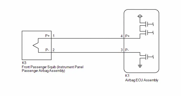
CAUTION / NOTICE / HINT
NOTICE:
-
After the ignition switch is turned off, there may be a waiting time before disconnecting the negative (-) auxiliary battery terminal.
Click here

HINT:
When disconnecting and reconnecting the auxiliary battery, there is an automatic learning function that completes learning when the respective system is used.
Click here


-
After replacing the airbag ECU assembly, refer to work procedure.
Click here


HINT:
-
To perform the simulation method, enter check mode (signal check) with the GTS.
Click here

-
Perform the simulation method while checking the Data List.
Click here

PROCEDURE
| 1. | CLEAR DTC |
Pre-procedure1
(a) Turn the ignition switch to ON, and wait for at least 60 seconds.
Procedure1
(b) Clear the DTCs stored in memory.
Body Electrical > SRS Airbag > Clear DTCsPost-procedure1
(c) Turn the ignition switch off.
|

| 2. | CHECK DTC |
Pre-procedure1
(a) Turn the ignition switch to ON, and wait for at least 60 seconds.
Procedure1
(b) Check for DTCs.
Body Electrical > SRS Airbag > Trouble Codes| Result | Proceed to |
|---|---|
| B001011 is output | A |
| B001011 is not output | B |
Post-procedure1
(c) None
| B |

| USE SIMULATION METHOD TO CHECK |
|

| 3. | CHECK CONNECTION OF CONNECTORS |
Pre-procedure1
(a) Turn the ignition switch off.
(b) Disconnect the cable from the negative (-) auxiliary battery terminal, and wait for at least 60 seconds.
Procedure1
(c) Check that the connectors are properly connected to the instrument panel passenger airbag assembly and airbag ECU assembly.
OK:
The connectors are properly connected.
Post-procedure1
(d) None
| NG |

| CONNECT CONNECTORS PROPERLY |
|

| 4. | CHECK CONNECTORS |
Pre-procedure1
| (a) Disconnect the airbag ECU assembly connector. |
|

(b) Disconnect the instrument panel passenger airbag assembly connector.
Procedure1
(c) Check that the terminals of the connectors are not deformed or damaged.
OK:
The terminals are not deformed or damaged.
(d) Check that the connectors are not loose, deformed or damaged.
OK:
The connector locking button is not disengaged, and the claw of the lock is not deformed or damaged.
Post-procedure1
(e) None
| NG |

| REPAIR OR REPLACE HARNESS OR CONNECTOR |
|

| 5. | CLEAR DTC |
Pre-procedure1
| (a) Connect the airbag ECU assembly connector. |
|
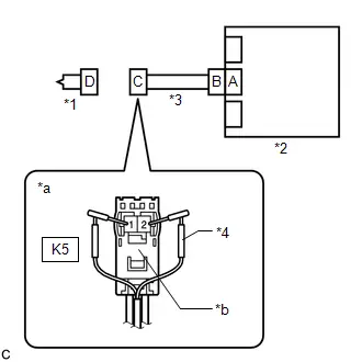
(b) Connect SST (resistance: 2.1 Ω) to connector C (orange connector).
CAUTION:
Never connect the tester to the instrument panel passenger airbag assembly for measurement, as this may lead to a serious injury due to airbag deployment.
NOTICE:
- Do not forcibly insert SST into the terminals of the connector when connecting SST.
- Insert SST straight into the terminals of the connector.
SST: 09843-18061
(c) Connect the cable to the negative (-) auxiliary battery terminal, and wait for at least 2 seconds.
(d) Turn the ignition switch to ON, and wait for at least 60 seconds.
Procedure1
(e) Clear the DTCs stored in memory.
Body Electrical > SRS Airbag > Clear DTCsPost-procedure1
(f) Turn the ignition switch off.
|

| 6. | CHECK INSTRUMENT PANEL PASSENGER AIRBAG ASSEMBLY |
Pre-procedure1
(a) Turn the ignition switch to ON, and wait for at least 60 seconds.
Procedure1
(b) Check for DTCs.
Body Electrical > SRS Airbag > Trouble Codes| Result | Proceed to |
|---|---|
| B001011 is not output | A |
| B001011 is output | B |
HINT:
Codes other than DTC B001011 may be output at this time, but they are not related to this check.
Post-procedure1
(c) Turn the ignition switch off.
(d) Disconnect the cable from the negative (-) auxiliary battery terminal, and wait for at least 60 seconds.
(e) Disconnect SST from connector C.
| A |

| REPLACE INSTRUMENT PANEL PASSENGER AIRBAG ASSEMBLY
|


|

| 7. | CHECK HARNESS AND CONNECTOR |
Pre-procedure1
(a) Disconnect the airbag ECU assembly connector.
Procedure1
| (b) Measure the resistance according to the value(s) in the table below. Standard Resistance:  Click Location & Routing(K5) Click Connector(K5) Click Location & Routing(K5) Click Connector(K5)
Result:
|
|
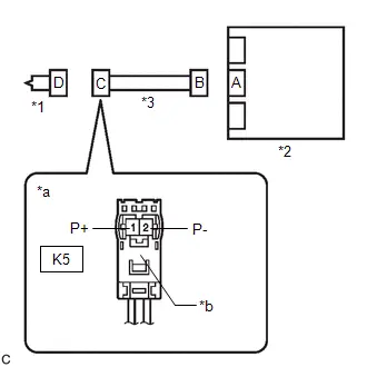
Post-procedure1
(c) None
| NG |

| REPAIR OR REPLACE HARNESS OR CONNECTOR |
|

| 8. | CLEAR DTC |
Pre-procedure1
| (a) Connect the airbag ECU assembly connector. |
|

(b) Connect the instrument panel passenger airbag assembly connector.
(c) Connect the cable to the negative (-) auxiliary battery terminal, and wait for at least 2 seconds.
(d) Turn the ignition switch to ON, and wait for at least 60 seconds.
Procedure1
(e) Clear the DTCs stored in memory.
Body Electrical > SRS Airbag > Clear DTCsPost-procedure1
(f) Turn the ignition switch off.
|

| 9. | CHECK DTC |
Pre-procedure1
(a) Turn the ignition switch to ON, and wait for at least 60 seconds.
Procedure1
(b) Check for DTCs.
Body Electrical > SRS Airbag > Trouble Codes| Result | Proceed to |
|---|---|
| B001011 is not output | A |
| B001011 is output | B |
HINT:
Codes other than DTC B001011 may be output at this time, but they are not related to this check.
Post-procedure1
(c) None
| A |

| USE SIMULATION METHOD TO CHECK |
| B |

| REPLACE AIRBAG ECU ASSEMBLY
|


Passenger Seat Belt Sensor Circuit Undetermined Failure (B005200)
DESCRIPTION
| DTC No. | Detection Item | DTC Detection Condition | Trouble Area | Warning Indicate | DTC Output from | Priority | Test Mode / Check Mode |
|---|---|---|---|---|---|---|---|
| B005200 | Passenger Seat Belt Sensor Circuit Undetermined Failure | When it is determined that the specified number of times or more is not achieved after the ignition switch is turned to ON. |
| Comes on | SRS Airbag | A | Does not apply to test/check mode |
WIRING DIAGRAM

CAUTION / NOTICE / HINT
NOTICE:
-
After the ignition switch is turned off, there may be a waiting time before disconnecting the negative (-) auxiliary battery terminal.
Click here

HINT:
When disconnecting and reconnecting the auxiliary battery, there is an automatic learning function that completes learning when the respective system is used.
Click here


-
After replacing the airbag ECU assembly, refer to work procedure.
Click here


PROCEDURE
| 1. | CHECK CONNECTION OF CONNECTORS |
Pre-procedure1
(a) Turn the ignition switch off.
(b) Disconnect the cable from the negative (-) auxiliary battery terminal, and wait for at least 60 seconds.
Procedure1
(c) Check that the connectors are properly connected to the airbag ECU assembly and front seat inner belt assembly RH.
OK:
The connectors are properly connected.
Post-procedure1
(d) None
| NG |

| CONNECT CONNECTORS PROPERLY |
|

| 2. | CHECK CONNECTORS |
Pre-procedure1
| (a) Disconnect the airbag ECU assembly connector. |
|

(b) Disconnect the front seat inner belt assembly RH connector.
Procedure1
(c) Check that the terminals of the connectors are not deformed or damaged.
OK:
The terminals are not deformed or damaged.
Post-procedure1
(d) None
| NG |

| REPAIR OR REPLACE HARNESS OR CONNECTOR |
|

| 3. | INSPECT FRONT SEAT INNER BELT ASSEMBLY RH |
Pre-procedure1
(a) Remove the front seat inner belt assembly RH.
HINT:
Click here


Procedure1
(b) Inspect the front seat inner belt assembly RH.
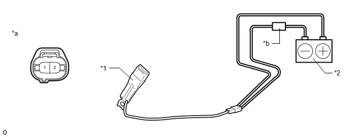
| *1 | Front Seat Inner Belt Assembly RH | *2 | Auxiliary Battery |
| *a | Component without harness connected (Front Seat Inner Belt Assembly RH) | *b | Tester |
Standard Current:
| Tester Connection | Condition | Specified Condition | Result |
|---|---|---|---|
| Tester positive ( ) - 2 Tester negative (-) - Auxiliary battery negative (-) | Seat belt fastened | 12.0 to 18.0 mA | mA |
| Tester positive ( ) - 2 Tester negative (-) - Auxiliary battery negative (-) | Seat belt not fastened | 4.0 to 7.0 mA | mA |
Post-procedure1
(c) None
| NG |

| REPLACE FRONT SEAT INNER BELT ASSEMBLY RH
|


|

| 4. | CHECK HARNESS AND CONNECTOR (CHECK FOR OPEN IN THE CIRCUIT) |
Pre-procedure1
| (a) Using a service wire, connect terminals 27 (RBE ) and 18 (GNDR) of connector B. NOTICE: Do not forcibly insert the service wire into the terminals of the connector when connecting a service wire. |
|

Procedure1
(b) Measure the resistance according to the value(s) in the table below.
Standard Resistance:
 Click Location & Routing(a16) Click Connector(a16)
 | Tester Connection | Condition | Specified Condition | Result |
|---|---|---|---|
| a16-1 - a16-2 | Always | Below 1 Ω | Ω |
Post-procedure1
(c) Disconnect the service wire from connector B.
| NG |

| REPAIR OR REPLACE HARNESS OR CONNECTOR |
|

| 5. | CHECK HARNESS AND CONNECTOR (CHECK FOR SHORT TO GROUND IN THE CIRCUIT) |
| (a) Measure the resistance according to the value(s) in the table below. Standard Resistance:  Click Location & Routing(a16) Click Connector(a16) Click Location & Routing(a16) Click Connector(a16)
|
|

| NG |

| REPAIR OR REPLACE HARNESS OR CONNECTOR |
|

| 6. | CHECK HARNESS AND CONNECTOR (CHECK FOR SHORT TO B IN THE CIRCUIT) |
Pre-procedure1
(a) Connect the cable to the negative (-) auxiliary battery terminal, and wait for at least 2 seconds.
(b) Turn the ignition switch to ON.
Procedure1
| (c) Measure the voltage according to the value(s) in the table below. Standard Voltage:  Click Location & Routing(a16) Click Connector(a16) Click Location & Routing(a16) Click Connector(a16)
Result:
|
|

Post-procedure1
(d) Turn the ignition switch off.
(e) Disconnect the cable from the negative (-) auxiliary battery terminal, and wait for at least 60 seconds.
| NG |

| REPAIR OR REPLACE HARNESS OR CONNECTOR |
|

| 7. | CLEAR DTC |
Pre-procedure1
| (a) Connect the airbag ECU assembly connector. |
|
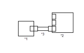
(b) Connect the front seat inner belt assembly RH connector.
(c) Connect the cable to the negative (-) auxiliary battery terminal, and wait for at least 2 seconds.
(d) Turn the ignition switch to ON, and wait for at least 60 seconds.
Procedure1
(e) Clear the DTCs stored in memory.
Body Electrical > SRS Airbag > Clear DTCsPost-procedure1
(f) Turn the ignition switch off.
|

| 8. | CHECK DTC |
Pre-procedure1
(a) Turn the ignition switch to ON, and wait for at least 60 seconds.
Procedure1
(b) Check for DTCs.
Body Electrical > SRS Airbag > Trouble Codes| Result | Proceed to |
|---|---|
| B005200 is output | A |
| B005200 is not output | B |
HINT:
Codes other than DTC B005200 may be output at this time, but they are not related to this check.
Post-procedure1
(c) None
| A |

| REPLACE AIRBAG ECU ASSEMBLY
|


| B |

| USE SIMULATION METHOD TO CHECK |
Passenger Seat Belt Sensor Circuit Short to Ground (B005211)
DESCRIPTION
| DTC No. | Detection Item | DTC Detection Condition | Trouble Area | Warning Indicate | DTC Output from | Priority | Test Mode / Check Mode |
|---|---|---|---|---|---|---|---|
| B005211 | Passenger Seat Belt Sensor Circuit Short to Ground | One of the following conditions is met:
|
| Comes on | SRS Airbag | A | Does not apply to test/check mode |
WIRING DIAGRAM
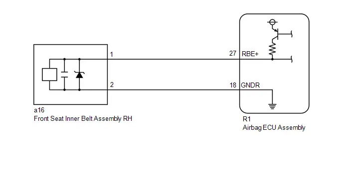
CAUTION / NOTICE / HINT
NOTICE:
-
After the ignition switch is turned off, there may be a waiting time before disconnecting the negative (-) auxiliary battery terminal.
Click here

HINT:
When disconnecting and reconnecting the auxiliary battery, there is an automatic learning function that completes learning when the respective system is used.
Click here


-
After replacing the airbag ECU assembly, refer to work procedure.
Click here


PROCEDURE
| 1. | CHECK CONNECTION OF CONNECTORS |
Pre-procedure1
(a) Turn the ignition switch off.
(b) Disconnect the cable from the negative (-) auxiliary battery terminal, and wait for at least 60 seconds.
Procedure1
(c) Check that the connectors are properly connected to the airbag ECU assembly and front seat inner belt assembly RH.
OK:
The connectors are properly connected.
Post-procedure1
(d) None
| NG |

| CONNECT CONNECTORS PROPERLY |
|

| 2. | CHECK CONNECTORS |
Pre-procedure1
| (a) Disconnect the airbag ECU assembly connector. |
|

(b) Disconnect the front seat inner belt assembly RH connector.
Procedure1
(c) Check that the terminals of the connectors are not deformed or damaged.
OK:
The terminals are not deformed or damaged.
Post-procedure1
(d) None
| NG |

| REPAIR OR REPLACE HARNESS OR CONNECTOR |
|

| 3. | CHECK HARNESS AND CONNECTOR (CHECK FOR SHORT IN THE CIRCUIT) |
| (a) Measure the resistance according to the value(s) in the table below. Standard Resistance:  Click Location & Routing(a16) Click Connector(a16) Click Location & Routing(a16) Click Connector(a16)
|
|

| NG |

| REPAIR OR REPLACE HARNESS OR CONNECTOR |
|

| 4. | CHECK HARNESS AND CONNECTOR (CHECK FOR SHORT TO GROUND IN THE CIRCUIT) |
| (a) Measure the resistance according to the value(s) in the table below. Standard Resistance:  Click Location & Routing(a16) Click Connector(a16) Click Location & Routing(a16) Click Connector(a16)
|
|
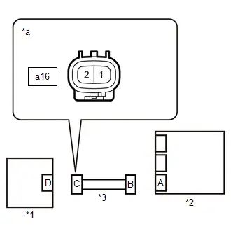
| NG |

| REPAIR OR REPLACE HARNESS OR CONNECTOR |
|

| 5. | CLEAR DTC |
Pre-procedure1
| (a) Connect the airbag ECU assembly connector. |
|
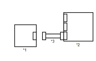
(b) Connect the cable to the negative (-) auxiliary battery terminal, and wait for at least 2 seconds.
(c) Turn the ignition switch to ON, and wait for at least 60 seconds.
Procedure1
(d) Clear the DTCs stored in memory.
Body Electrical > SRS Airbag > Clear DTCsPost-procedure1
(e) Turn the ignition switch off.
|

| 6. | CHECK DTC |
Pre-procedure1
(a) Turn the ignition switch to ON, and wait for at least 60 seconds.
Procedure1
(b) Check for DTCs.
Body Electrical > SRS Airbag > Trouble Codes| Result | Proceed to |
|---|---|
| B005211 is output | A |
| B005211 is not output | B |
HINT:
Codes other than DTC B005211 may be output at this time, but they are not related to this check.
Post-procedure1
(c) None
| A |

| REPLACE AIRBAG ECU ASSEMBLY
|


| B |

| REPLACE FRONT SEAT INNER BELT ASSEMBLY RH
|


Passenger Seat Belt Sensor Circuit Open (B005213)
DESCRIPTION
| DTC No. | Detection Item | DTC Detection Condition | Trouble Area | Warning Indicate | DTC Output from | Priority | Test Mode / Check Mode |
|---|---|---|---|---|---|---|---|
| B005213 | Passenger Seat Belt Sensor Circuit Open | One of the following conditions is met:
|
| Comes on | SRS Airbag | A | Does not apply to test/check mode |
WIRING DIAGRAM

CAUTION / NOTICE / HINT
NOTICE:
-
After the ignition switch is turned off, there may be a waiting time before disconnecting the negative (-) auxiliary battery terminal.
Click here

HINT:
When disconnecting and reconnecting the auxiliary battery, there is an automatic learning function that completes learning when the respective system is used.
Click here


-
After replacing the airbag ECU assembly, refer to work procedure.
Click here


PROCEDURE
| 1. | CHECK CONNECTION OF CONNECTORS |
Pre-procedure1
(a) Turn the ignition switch off.
(b) Disconnect the cable from the negative (-) auxiliary battery terminal, and wait for at least 60 seconds.
Procedure1
(c) Check that the connectors are properly connected to the airbag ECU assembly and front seat inner belt assembly RH.
OK:
The connectors are properly connected.
Post-procedure1
(d) None
| NG |

| CONNECT CONNECTORS PROPERLY |
|

| 2. | CHECK CONNECTORS |
Pre-procedure1
| (a) Disconnect the airbag ECU assembly connector. |
|
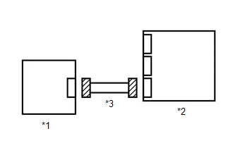
(b) Disconnect the front seat inner belt assembly RH connector.
Procedure1
(c) Check that the terminals of the connectors are not deformed or damaged.
OK:
The terminals are not deformed or damaged.
Post-procedure1
(d) None
| NG |

| REPAIR OR REPLACE HARNESS OR CONNECTOR |
|

| 3. | CHECK HARNESS AND CONNECTOR (CHECK FOR OPEN IN THE CIRCUIT) |
Pre-procedure1
| (a) Using a service wire, connect terminals 27 (RBE ) and 18 (GNDR) of connector B. NOTICE: Do not forcibly insert the service wire into the terminals of the connector when connecting a service wire. |
|
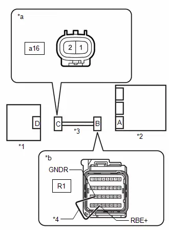
Procedure1
(b) Measure the resistance according to the value(s) in the table below.
Standard Resistance:
 Click Location & Routing(a16) Click Connector(a16)
 | Tester Connection | Condition | Specified Condition | Result |
|---|---|---|---|
| a16-1 - a16-2 | Always | Below 1 Ω | Ω |
Post-procedure1
(c) Disconnect the service wire from connector B.
| NG |

| REPAIR OR REPLACE HARNESS OR CONNECTOR |
|

| 4. | CLEAR DTC |
Pre-procedure1
| (a) Using a service wire, connect terminals 1 and 2 of connector C. NOTICE: Do not forcibly insert the service wire into the terminals of the connector when connecting a service wire. |
|
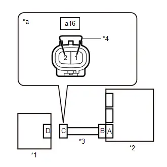
(b) Connect the airbag ECU assembly connector.
(c) Connect the cable to the negative (-) auxiliary battery terminal, and wait for at least 2 seconds.
(d) Turn the ignition switch to ON, and wait for at least 60 seconds.
Procedure1
(e) Clear the DTCs stored in memory.
Body Electrical > SRS Airbag > Clear DTCsPost-procedure1
(f) Turn the ignition switch off.
|

| 5. | CHECK DTC |
Pre-procedure1
(a) Turn the ignition switch to ON, and wait for at least 60 seconds.
Procedure1
(b) Check for DTCs.
Body Electrical > SRS Airbag > Trouble Codes| Result | Proceed to |
|---|---|
| B005213 is output | A |
| B005213 is not output | B |
HINT:
Codes other than DTC B005213 may be output at this time, but they are not related to this check.
Post-procedure1
(c) Turn the ignition switch off.
(d) Disconnect the cable from the negative (-) auxiliary battery terminal, and wait for at least 60 seconds.
(e) Disconnect the service wire from connector C.
| A |

| REPLACE AIRBAG ECU ASSEMBLY
|


| B |

| REPLACE FRONT SEAT INNER BELT ASSEMBLY RH
|


Left Frontal Restraints Sensor Value of Signal Protection Calculation Incorrect (B009083)
DESCRIPTION
| DTC No. | Detection Item | DTC Detection Condition | Trouble Area | Warning Indicate | DTC Output from | Priority | Test Mode / Check Mode |
|---|---|---|---|---|---|---|---|
| B009083 | Left Frontal Restraints Sensor Value of Signal Protection Calculation Incorrect |
|
| Comes on | SRS Airbag | A | Does not apply to test/check mode |
WIRING DIAGRAM
Click here

CAUTION / NOTICE / HINT
NOTICE:
-
After the ignition switch is turned off, there may be a waiting time before disconnecting the negative (-) auxiliary battery terminal.
Click here

HINT:
When disconnecting and reconnecting the auxiliary battery, there is an automatic learning function that completes learning when the respective system is used.
Click here


-
After replacing the airbag ECU assembly, refer to work procedure.
Click here


PROCEDURE
| 1. | CHECK DTC |
Pre-procedure1
(a) Turn the ignition switch to ON, and wait for at least 60 seconds.
Procedure1
(b) Check for DTCs.
Body Electrical > SRS Airbag > Trouble Codes| Result | Proceed to |
|---|---|
| B009083 is output | A |
| B009083 is not output | B |
Post-procedure1
(c) None
| B |

| USE SIMULATION METHOD TO CHECK |
|

| 2. | CHECK CONNECTION OF CONNECTORS |
Pre-procedure1
(a) Turn the ignition switch off.
(b) Disconnect the cable from the negative (-) auxiliary battery terminal, and wait for at least 60 seconds.
Procedure1
(c) Check that the connectors are properly connected to the airbag ECU assembly and front airbag sensor LH.
OK:
The connectors are properly connected.
Post-procedure1
(d) None
| NG |

| CONNECT CONNECTORS PROPERLY |
|

| 3. | CLEAR DTC |
Pre-procedure1
| (a) Interchange the front airbag sensor LH with RH and connect the connectors to them. |
|

(b) Connect the cable to the negative (-) auxiliary battery terminal, and wait for at least 2 seconds.
(c) Turn the ignition switch to ON, and wait for at least 60 seconds.
Procedure1
(d) Clear the DTCs stored in memory.
Body Electrical > SRS Airbag > Clear DTCsPost-procedure1
(e) Turn the ignition switch off.
|

| 4. | CHECK FRONT AIRBAG SENSOR LH |
Pre-procedure1
(a) Turn the ignition switch to ON, and wait for at least 60 seconds.
Procedure1
(b) Check for DTCs.
Body Electrical > SRS Airbag > Trouble Codes| Result | Proceed to |
|---|---|
| B009083 is output | A |
| B009583 is output | B |
| B009083 and B009583 are not output | C |
HINT:
Codes other than DTCs B009083 and B009583 may be output at this time, but they are not related to this check.
Post-procedure1
(c) Turn the ignition switch off.
(d) Disconnect the cable from the negative (-) auxiliary battery terminal, and wait for at least 60 seconds.
(e) Return the front airbag sensor RH and LH to their original positions and connect the connectors to them.
| A |

| REPLACE AIRBAG ECU ASSEMBLY
|


| B |

| REPLACE FRONT AIRBAG SENSOR LH
|


| C |

| USE SIMULATION METHOD TO CHECK |
Left Frontal Restraints Sensor Missing Message (B009087)
DESCRIPTION
| DTC No. | Detection Item | DTC Detection Condition | Trouble Area | Warning Indicate | DTC Output from | Priority | Test Mode / Check Mode |
|---|---|---|---|---|---|---|---|
| B009087 | Left Frontal Restraints Sensor Missing Message |
|
| Comes on | SRS Airbag | A | Does not apply to test/check mode |
WIRING DIAGRAM
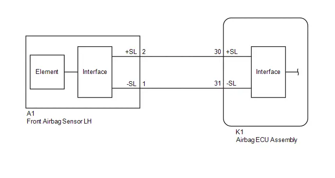
CAUTION / NOTICE / HINT
NOTICE:
-
After the ignition switch is turned off, there may be a waiting time before disconnecting the negative (-) auxiliary battery terminal.
Click here

HINT:
When disconnecting and reconnecting the auxiliary battery, there is an automatic learning function that completes learning when the respective system is used.
Click here


-
After replacing the airbag ECU assembly, refer to work procedure.
Click here


PROCEDURE
| 1. | CHECK CONNECTION OF CONNECTORS |
Pre-procedure1
(a) Turn the ignition switch off.
(b) Disconnect the cable from the negative (-) auxiliary battery terminal, and wait for at least 60 seconds.
Procedure1
(c) Check that the connectors are properly connected to the airbag ECU assembly and front airbag sensor LH.
OK:
The connectors are properly connected.
Post-procedure1
(d) None
| NG |

| CONNECT CONNECTORS PROPERLY |
|

| 2. | CHECK CONNECTORS |
Pre-procedure1
| (a) Disconnect the airbag ECU assembly connector. |
|

(b) Disconnect the front airbag sensor LH connector.
Procedure1
(c) Check that the terminals of the connectors are not deformed or damaged.
OK:
The terminals are not deformed or damaged.
Post-procedure1
(d) None
| NG |

| REPAIR OR REPLACE HARNESS OR CONNECTOR |
|

| 3. | CHECK HARNESS AND CONNECTOR (CHECK FOR SHORT IN THE CIRCUIT) |
| (a) Measure the resistance according to the value(s) in the table below. Standard Resistance:  Click Location & Routing(A1) Click Connector(A1) Click Location & Routing(A1) Click Connector(A1)
Result:
|
|

| NG |

| REPAIR OR REPLACE HARNESS OR CONNECTOR |
|

| 4. | CHECK HARNESS AND CONNECTOR (CHECK FOR OPEN IN THE CIRCUIT) |
Pre-procedure1
| (a) Using a service wire, connect terminals 30 ( SL) and 31 (-SL) of connector B. NOTICE: Do not forcibly insert the service wire into the terminals of the connector when connecting a service wire. |
|
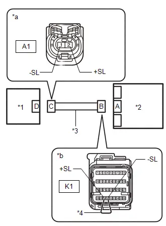
Procedure1
(b) Measure the resistance according to the value(s) in the table below.
Standard Resistance:
 Click Location & Routing(A1) Click Connector(A1)
 | Tester Connection | Condition | Specified Condition | Result |
|---|---|---|---|
| A1-2 ( SL) - A1-1 (-SL) | Always | Below 1 Ω | Ω |
Post-procedure1
(c) Disconnect the service wire from connector B.
| NG |

| REPAIR OR REPLACE HARNESS OR CONNECTOR |
|

| 5. | CHECK HARNESS AND CONNECTOR (CHECK FOR SHORT TO GROUND IN THE CIRCUIT) |
| (a) Measure the resistance according to the value(s) in the table below. Standard Resistance:  Click Location & Routing(A1) Click Connector(A1) Click Location & Routing(A1) Click Connector(A1)
|
|

| NG |

| REPAIR OR REPLACE HARNESS OR CONNECTOR |
|

| 6. | CHECK HARNESS AND CONNECTOR (CHECK FOR SHORT TO B IN THE CIRCUIT) |
Pre-procedure1
(a) Connect the cable to the negative (-) auxiliary battery terminal, and wait for at least 2 seconds.
(b) Turn the ignition switch to ON.
Procedure1
| (c) Measure the voltage according to the value(s) in the table below. Standard Voltage:  Click Location & Routing(A1) Click Connector(A1) Click Location & Routing(A1) Click Connector(A1)
Result:
|
|
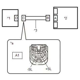
Post-procedure1
(d) Turn the ignition switch off.
(e) Disconnect the cable from the negative (-) auxiliary battery terminal, and wait for at least 60 seconds.
| NG |

| REPAIR OR REPLACE HARNESS OR CONNECTOR |
|

| 7. | CLEAR DTC |
Pre-procedure1
| (a) Connect the airbag ECU assembly connector. |
|
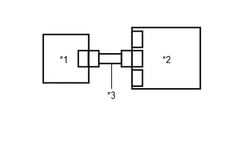
(b) Interchange the front airbag sensor LH with RH and connect the connectors to them.
(c) Connect the cable to the negative (-) auxiliary battery terminal, and wait for at least 2 seconds.
(d) Turn the ignition switch to ON, and wait for at least 60 seconds.
Procedure1
(e) Clear the DTCs stored in memory.
Body Electrical > SRS Airbag > Clear DTCsPost-procedure1
(f) Turn the ignition switch off.
|

| 8. | CHECK FRONT AIRBAG SENSOR LH |
Pre-procedure1
(a) Turn the ignition switch to ON, and wait for at least 60 seconds.
Procedure1
(b) Check for DTCs.
Body Electrical > SRS Airbag > Trouble Codes| Result | Proceed to |
|---|---|
| B009087 is output | A |
| B009587 is output | B |
| B009087 and B009587 are not output | C |
HINT:
Codes other than DTCs B009087 and B009587 may be output at this time, but they are not related to this check.
Post-procedure1
(c) Turn the ignition switch off.
(d) Disconnect the cable from the negative (-) auxiliary battery terminal, and wait for at least 60 seconds.
(e) Return the front airbag sensor RH and LH to their original positions and connect the connectors to them.
| A |

| REPLACE AIRBAG ECU ASSEMBLY
|


| B |

| REPLACE FRONT AIRBAG SENSOR LH
|


| C |

| USE SIMULATION METHOD TO CHECK |
Right Side Restraints Sensor 5 Signal Plausibility Failure (B009E64)
DESCRIPTION
| DTC No. | Detection Item | DTC Detection Condition | Trouble Area | Warning Indicate | DTC Output from | Priority | Test Mode / Check Mode |
|---|---|---|---|---|---|---|---|
| B009E64 | Right Side Restraints Sensor 5 Signal Plausibility Failure | The pressure of the side airbag pressure sensor RH is a certain value or more. |
| Comes on | SRS Airbag | A | Does not apply to test/check mode |
WIRING DIAGRAM
Click here

CAUTION / NOTICE / HINT
NOTICE:
-
After the ignition switch is turned off, there may be a waiting time before disconnecting the negative (-) auxiliary battery terminal.
Click here

HINT:
When disconnecting and reconnecting the auxiliary battery, there is an automatic learning function that completes learning when the respective system is used.
Click here


-
After replacing the airbag ECU assembly, refer to work procedure.
Click here


PROCEDURE
| 1. | CLEAR DTC |
Pre-procedure1
| (a) Turn the ignition switch off. |
|
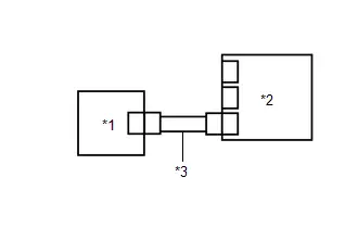
(b) Disconnect the cable from the negative (-) auxiliary battery terminal, and wait for at least 60 seconds.
(c) Interchange the side airbag pressure sensor RH with LH and connect the connectors to them.
(d) Connect the cable to the negative (-) auxiliary battery terminal, and wait for at least 2 seconds.
(e) Turn the ignition switch to ON, and wait for at least 60 seconds.
Procedure1
(f) Clear the DTCs stored in memory.
Body Electrical > SRS Airbag > Clear DTCsPost-procedure1
(g) Turn the ignition switch off.
|

| 2. | CHECK SIDE AIRBAG PRESSURE SENSOR RH |
Pre-procedure1
(a) Turn the ignition switch to ON, and wait for at least 60 seconds.
Procedure1
(b) Check for DTCs.
Body Electrical > SRS Airbag > Trouble Codes| Result | Proceed to |
|---|---|
| B009E64 is output | A |
| B009B64 is output | B |
| B009B64 and B009E64 are not output | C |
HINT:
Codes other than DTCs B009B64 and B009E64 may be output at this time, but they are not related to this check.
Post-procedure1
(c) Turn the ignition switch off.
(d) Disconnect the cable from the negative (-) auxiliary battery terminal, and wait for at least 60 seconds.
(e) Return the side airbag pressure sensor LH and RH to their original positions and connect the connectors to them.
| A |

| REPLACE AIRBAG ECU ASSEMBLY
|


| B |

| REPLACE SIDE AIRBAG PRESSURE SENSOR RH
|


| C |

| USE SIMULATION METHOD TO CHECK |
Restraint System Malfunction Indicator 1 Circuit Short to Battery (B00D212)
DESCRIPTION
| DTC No. | Detection Item | DTC Detection Condition | Trouble Area | Warning Indicate | DTC Output from | Priority | Test Mode / Check Mode |
|---|---|---|---|---|---|---|---|
| B00D212 | Restraint System Malfunction Indicator 1 Circuit Short to Battery |
|
| Comes on | SRS Airbag | A | Does not apply to test/check mode |
WIRING DIAGRAM
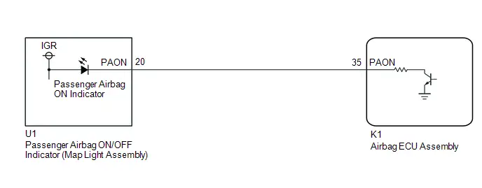
CAUTION / NOTICE / HINT
NOTICE:
-
After the ignition switch is turned off, there may be a waiting time before disconnecting the negative (-) auxiliary battery terminal.
Click here

HINT:
When disconnecting and reconnecting the auxiliary battery, there is an automatic learning function that completes learning when the respective system is used.
Click here


-
After replacing the airbag ECU assembly, refer to work procedure.
Click here


PROCEDURE
| 1. | CHECK CONNECTION OF CONNECTORS |
Pre-procedure1
(a) Turn the ignition switch off.
(b) Disconnect the cable from the negative (-) auxiliary battery terminal, and wait for at least 60 seconds.
Procedure1
(c) Check that the connectors are properly connected to the airbag ECU assembly and map light assembly.
OK:
The connectors are properly connected.
Post-procedure1
(d) None
| NG |

| CONNECT CONNECTORS PROPERLY |
|

| 2. | CHECK CONNECTORS |
Pre-procedure1
| (a) Disconnect the airbag ECU assembly connector. |
|
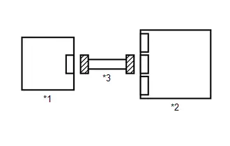
(b) Disconnect the map light assembly connector.
Procedure1
(c) Check that the terminals of the connectors are not deformed or damaged.
OK:
The terminals are not deformed or damaged.
Post-procedure1
(d) None
| NG |

| REPAIR OR REPLACE HARNESS OR CONNECTOR |
|

| 3. | CHECK HARNESS AND CONNECTOR (CHECK FOR SHORT TO B IN THE CIRCUIT) |
Pre-procedure1
(a) Connect the cable to the negative (-) auxiliary battery terminal, and wait for at least 2 seconds.
(b) Turn the ignition switch to ON.
Procedure1
| (c) Measure the voltage according to the value(s) in the table below. Standard Voltage:  Click Location & Routing(K1,U1) Click Connector(K1) Click Connector(U1) Click Location & Routing(K1,U1) Click Connector(K1) Click Connector(U1)
Result:
|
|

Post-procedure1
(d) Turn the ignition switch off.
(e) Disconnect the cable from the negative (-) auxiliary battery terminal, and wait for at least 60 seconds.
| NG |

| REPAIR OR REPLACE HARNESS OR CONNECTOR |
|

| 4. | CHECK PASSENGER AIRBAG ON/OFF INDICATOR |
Pre-procedure1
| (a) Connect the map light assembly connector. |
|
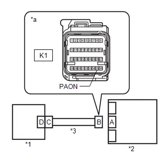
(b) Using a service wire, connect terminal 35 (PAON) of connector B and body ground.
NOTICE:
Do not forcibly insert the service wire into the terminals of the connector when connecting a service wire.
(c) Connect the cable to the negative (-) auxiliary battery terminal, and wait for at least 2 seconds.
(d) Turn the ignition switch to ON.
Procedure1
(e) Check the passenger airbag ON/OFF indicator operation.
OK:
The passenger airbag ON/OFF indicator "ON" come on.
Post-procedure1
(f) Turn the ignition switch off.
(g) Disconnect the cable from the negative (-) auxiliary battery terminal, and wait for at least 60 seconds.
(h) Disconnect the service wire from connector B.
| OK |

| REPLACE AIRBAG ECU ASSEMBLY
|


| NG |

| REPLACE MAP LIGHT ASSEMBLY |
Restraint System Malfunction Indicator 1 Circuit Short to Ground or Open (B00D214)
DESCRIPTION
| DTC No. | Detection Item | DTC Detection Condition | Trouble Area | Warning Indicate | DTC Output from | Priority | Test Mode / Check Mode |
|---|---|---|---|---|---|---|---|
| B00D214 | Restraint System Malfunction Indicator 1 Circuit Short to Ground or Open |
|
| Comes on | SRS Airbag | A | Does not apply to test/check mode |
WIRING DIAGRAM
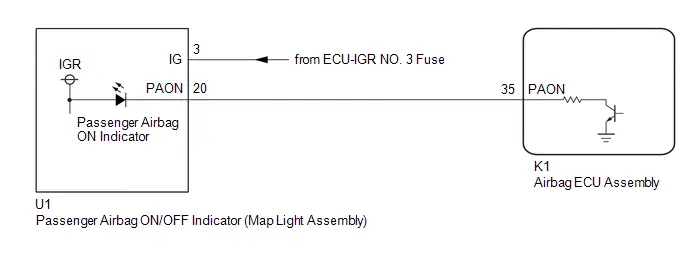
CAUTION / NOTICE / HINT
NOTICE:
-
After the ignition switch is turned off, there may be a waiting time before disconnecting the negative (-) auxiliary battery terminal.
Click here

HINT:
When disconnecting and reconnecting the auxiliary battery, there is an automatic learning function that completes learning when the respective system is used.
Click here


-
After replacing the airbag ECU assembly, refer to work procedure.
Click here


PROCEDURE
| 1. | CHECK PASSENGER AIRBAG ON/OFF INDICATOR CONDITION |
Pre-procedure1
(a) Turn the ignition switch to ON.
Procedure1
(b) Check the passenger airbag ON/OFF indicator operation.
HINT:
Refer to the normal condition of the passenger airbag ON/OFF indicator.
Click here

| Result | Proceed to |
|---|---|
| Passenger airbag ON/OFF indicator "ON" is always on. | A |
| Passenger airbag ON/OFF indicator "ON" is always off. | B |
Post-procedure1
(c) None
| B |

| GO TO STEP 6 |
|

| 2. | CHECK CONNECTION OF CONNECTORS |
Pre-procedure1
(a) Turn the ignition switch off.
(b) Disconnect the cable from the negative (-) auxiliary battery terminal, and wait for at least 60 seconds.
Procedure1
(c) Check that the connectors are properly connected to the airbag ECU assembly and map light assembly.
OK:
The connectors are properly connected.
Post-procedure1
(d) None
| NG |

| CONNECT CONNECTORS PROPERLY |
|

| 3. | CHECK CONNECTORS |
Pre-procedure1
| (a) Disconnect the airbag ECU assembly connector. |
|

(b) Disconnect the map light assembly connector.
Procedure1
(c) Check that the terminals of the connectors are not deformed or damaged.
OK:
The terminals are not deformed or damaged.
Post-procedure1
(d) None
| NG |

| REPAIR OR REPLACE HARNESS OR CONNECTOR |
|

| 4. | CHECK HARNESS AND CONNECTOR (CHECK FOR SHORT TO GROUND IN THE CIRCUIT) |
| (a) Measure the resistance according to the value(s) in the table below. Standard Resistance:  Click Location & Routing(K1,U1) Click Connector(K1) Click Connector(U1) Click Location & Routing(K1,U1) Click Connector(K1) Click Connector(U1)
|
|
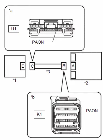
| NG |

| REPAIR OR REPLACE HARNESS OR CONNECTOR |
|

| 5. | CHECK PASSENGER AIRBAG ON/OFF INDICATOR |
Pre-procedure1
| (a) Connect the map light assembly connector. |
|
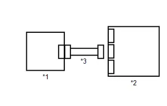
(b) Connect the cable to the negative (-) auxiliary battery terminal, and wait for at least 2 seconds.
(c) Turn the ignition switch to ON.
Procedure1
(d) Check the passenger airbag ON/OFF indicator operation.
OK:
The passenger airbag ON/OFF indicator "ON" does not come on.
Post-procedure1
(e) None
| OK |

| REPLACE AIRBAG ECU ASSEMBLY
|


| NG |

| REPLACE MAP LIGHT ASSEMBLY |
| 6. | CHECK CONNECTION OF CONNECTORS |
Pre-procedure1
(a) Turn the ignition switch off.
(b) Disconnect the cable from the negative (-) auxiliary battery terminal, and wait for at least 60 seconds.
Procedure1
(c) Check that the connectors are properly connected to the airbag ECU assembly and map light assembly.
OK:
The connectors are properly connected.
Post-procedure1
(d) None
| NG |

| CONNECT CONNECTORS PROPERLY |
|

| 7. | CHECK CONNECTORS |
Pre-procedure1
| (a) Disconnect the airbag ECU assembly connector. |
|

(b) Disconnect the map light assembly connector.
Procedure1
(c) Check that the terminals of the connectors are not deformed or damaged.
OK:
The terminals are not deformed or damaged.
Post-procedure1
(d) None
| NG |

| REPAIR OR REPLACE HARNESS OR CONNECTOR |
|

| 8. | CHECK HARNESS AND CONNECTOR (CHECK FOR OPEN IN THE CIRCUIT) |
| (a) Measure the resistance according to the value(s) in the table below. Standard Resistance:  Click Location & Routing(K1,U1) Click Connector(K1) Click Connector(U1) Click Location & Routing(K1,U1) Click Connector(K1) Click Connector(U1)
|
|

| NG |

| REPAIR OR REPLACE HARNESS OR CONNECTOR |
|

| 9. | CHECK HARNESS AND CONNECTOR (POWER SOURCE VOLTAGE) |
Pre-procedure1
(a) Connect the cable to the negative (-) auxiliary battery terminal, and wait for at least 2 seconds.
(b) Turn the ignition switch to ON.
Procedure1
| (c) Measure the voltage according to the value(s) in the table below. Standard Voltage:  Click Location & Routing(U1) Click Connector(U1) Click Location & Routing(U1) Click Connector(U1)
Result:
|
|
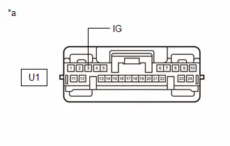
Post-procedure1
(d) Turn the ignition switch off.
(e) Disconnect the cable from the negative (-) auxiliary battery terminal, and wait for at least 60 seconds.
| NG |

| REPAIR OR REPLACE HARNESS OR CONNECTOR |
|

| 10. | CHECK PASSENGER AIRBAG ON/OFF INDICATOR |
Pre-procedure1
| (a) Connect the map light assembly connector. |
|

(b) Using a service wire, connect terminal 35 (PAON) of connector B and body ground.
NOTICE:
Do not forcibly insert the service wire into the terminals of the connector when connecting a service wire.
(c) Connect the cable to the negative (-) auxiliary battery terminal, and wait for at least 2 seconds.
(d) Turn the ignition switch to ON.
Procedure1
(e) Check the passenger airbag ON/OFF indicator operation.
OK:
The passenger airbag ON/OFF indicator "ON" come on.
Post-procedure1
(f) Turn the ignition switch off.
(g) Disconnect the cable from the negative (-) auxiliary battery terminal, and wait for at least 60 seconds.
(h) Disconnect the service wire from connector B.
| OK |

| REPLACE AIRBAG ECU ASSEMBLY
|


| NG |

| REPLACE MAP LIGHT ASSEMBLY |
Airbag ECU (Microcomputer) Internal Electronic Failure (B116049,...,P05BB00)
DESCRIPTION
| DTC No. | Detection Item | DTC Detection Condition | Trouble Area | Warning Indicate | DTC Output from | Priority | Test Mode / Check Mode |
|---|---|---|---|---|---|---|---|
| B116049 | Airbag ECU (Microcomputer) Internal Electronic Failure | Airbag ECU assembly malfunction | Airbag ECU assembly | Comes on | SRS Airbag | A | Does not apply to test/check mode |
| B11609E | Airbag ECU (Microcomputer) Stuck On | Airbag ECU assembly malfunction | Airbag ECU assembly | Comes on | SRS Airbag | A | Does not apply to test/check mode |
| B116149 | Airbag ECU (Main ASIC) Internal Electronic Failure | Airbag ECU assembly malfunction | Airbag ECU assembly | Comes on | SRS Airbag | A | Does not apply to test/check mode |
| B11619E | Airbag ECU (Main ASIC) Stuck On | Airbag ECU assembly malfunction | Airbag ECU assembly | Comes on | SRS Airbag | A | Does not apply to test/check mode |
| B116311 | Airbag ECU (IC and Device) Circuit Short to Ground | Airbag ECU assembly malfunction | Airbag ECU assembly | Comes on | SRS Airbag | A | Does not apply to test/check mode |
| B116349 | Airbag ECU (IC and Device) Internal Electronic Failure | Airbag ECU assembly malfunction | Airbag ECU assembly | Comes on | SRS Airbag | A | Does not apply to test/check mode |
| B11639E | Airbag ECU (IC and Device) Stuck On | Airbag ECU assembly malfunction | Airbag ECU assembly | Comes on | SRS Airbag | A | Does not apply to test/check mode |
| B11639F | Airbag ECU (IC and Device) Stuck Off | Airbag ECU assembly malfunction | Airbag ECU assembly | Comes on | SRS Airbag | A | Does not apply to test/check mode |
| B116449 | Airbag ECU (G Sensor 1) Internal Electronic Failure | Airbag ECU assembly malfunction | Airbag ECU assembly | Comes on | SRS Airbag | A | Does not apply to test/check mode |
| B116483 | Airbag ECU (G Sensor 1) Value of Signal Protection Calculation Incorrect | Airbag ECU assembly malfunction | Airbag ECU assembly | Comes on | SRS Airbag | A | Does not apply to test/check mode |
| B116484 | Airbag ECU (G Sensor 1) Signal Below Allowable Range | Airbag ECU assembly malfunction | Airbag ECU assembly | Comes on | SRS Airbag | A | Does not apply to test/check mode |
| B116485 | Airbag ECU (G Sensor 1) Signal Above Allowable Range | Airbag ECU assembly malfunction | Airbag ECU assembly | Comes on | SRS Airbag | A | Does not apply to test/check mode |
| B116549 | Airbag ECU (G Sensor 2) Internal Electronic Failure | Airbag ECU assembly malfunction | Airbag ECU assembly | Comes on | SRS Airbag | A | Does not apply to test/check mode |
| B116583 | Airbag ECU (G Sensor 2) Value of Signal Protection Calculation Incorrect | Airbag ECU assembly malfunction | Airbag ECU assembly | Comes on | SRS Airbag | A | Does not apply to test/check mode |
| B116584 | Airbag ECU (G Sensor 2) Signal Below Allowable Range | Airbag ECU assembly malfunction | Airbag ECU assembly | Comes on | SRS Airbag | A | Does not apply to test/check mode |
| B116585 | Airbag ECU (G Sensor 2) Signal Above Allowable Range | Airbag ECU assembly malfunction | Airbag ECU assembly | Comes on | SRS Airbag | A | Does not apply to test/check mode |
| B116649 | Airbag ECU (G Sensor 3) Internal Electronic Failure | Airbag ECU assembly malfunction | Airbag ECU assembly | Comes on | SRS Airbag | A | Does not apply to test/check mode |
| B116683 | Airbag ECU (G Sensor 3) Value of Signal Protection Calculation Incorrect | Airbag ECU assembly malfunction | Airbag ECU assembly | Comes on | SRS Airbag | A | Does not apply to test/check mode |
| B116684 | Airbag ECU (G Sensor 3) Signal Below Allowable Range | Airbag ECU assembly malfunction | Airbag ECU assembly | Comes on | SRS Airbag | A | Does not apply to test/check mode |
| B116685 | Airbag ECU (G Sensor 3) Signal Above Allowable Range | Airbag ECU assembly malfunction | Airbag ECU assembly | Comes on | SRS Airbag | A | Does not apply to test/check mode |
| B116749 | Airbag ECU (Roll Sensor) Internal Electronic Failure | Airbag ECU assembly malfunction | Airbag ECU assembly | Comes on | SRS Airbag | A | Does not apply to test/check mode |
| B116783 | Airbag ECU (Roll Sensor) Value of Signal Protection Calculation Incorrect | Airbag ECU assembly malfunction | Airbag ECU assembly | Comes on | SRS Airbag | A | Does not apply to test/check mode |
| B116784 | Airbag ECU (Roll Sensor) Signal Below Allowable Range | Airbag ECU assembly malfunction | Airbag ECU assembly | Comes on | SRS Airbag | A | Does not apply to test/check mode |
| B116785 | Airbag ECU (Roll Sensor) Signal Above Allowable Range | Airbag ECU assembly malfunction | Airbag ECU assembly | Comes on | SRS Airbag | A | Does not apply to test/check mode |
| B116800 | Airbag ECU Failure (Write Inhibit of EDR) | Airbag ECU assembly malfunction | Airbag ECU assembly | Comes on | SRS Airbag | A | Does not apply to test/check mode |
| P05BB00 | Restraints Deployed | Airbag ECU assembly malfunction | Airbag ECU assembly | Comes on | SRS Airbag | A | Does not apply to test/check mode |
CAUTION / NOTICE / HINT
NOTICE:
After replacing the airbag ECU assembly, refer to work procedure.
Click here


HINT:
If a DTC (except B116049, B11609E, B116149, B11619E, B116311, B116349, B11639E, B11639F, B116449, B116483, B116484, B116485, B116549, B116583, B116584, B116585, B116649, B116683, B116684, B116685, B116749, B116783, B116784, B116785, B116800 or P05BB00) is output at the same time as B116049, B11609E, B116149, B11619E, B116311, B116349, B11639E, B11639F, B116449, B116483, B116484, B116485, B116549, B116583, B116584, B116585, B116649, B116683, B116684, B116685, B116749, B116783, B116784, B116785, B116800 or P05BB00, repair the malfunction from that DTC first.
PROCEDURE
| 1. | CHECK DTC |
Pre-procedure1
(a) Turn the ignition switch to ON, and wait for at least 60 seconds.
Procedure1
(b) Check for DTCs.
Body Electrical > SRS Airbag > Trouble Codes| Result | Proceed to |
|---|---|
| B116049, B11609E, B116149, B11619E, B116311, B116349, B11639E, B11639F, B116449, B116483, B116484, B116485, B116549, B116583, B116584, B116585, B116649, B116683, B116684, B116685, B116749, B116783, B116784, B116785, B116800, P05BB00 and other DTCs are output | A |
| B116049, B11609E, B116149, B11619E, B116311, B116349, B11639E, B11639F, B116449, B116483, B116484, B116485, B116549, B116583, B116584, B116585, B116649, B116683, B116684, B116685, B116749, B116783, B116784, B116785, B116800 or P05BB00 is output | B |
NOTICE:
If only DTC B116049, B11609E, B116149, B11619E, B116311, B116349, B11639E, B11639F, B116449, B116483, B116484, B116485, B116549, B116583, B116584, B116585, B116649, B116683, B116684, B116685, B116749, B116783, B116784, B116785, B116800 or P05BB00 is output, do not clear the DTCs. Replace the airbag ECU assembly.
HINT:
If any DTCs other than DTC B116049, B11609E, B116149, B11619E, B116311, B116349, B11639E, B11639F, B116449, B116483, B116484, B116485, B116549, B116583, B116584, B116585, B116649, B116683, B116684, B116685, B116749, B116783, B116784, B116785, B116800 or P05BB00 are also output, troubleshoot those DTCs first.
Post-procedure1
(c) None
| A |

| GO TO DIAGNOSTIC TROUBLE CODE CHART
|


| B |

| REPLACE AIRBAG ECU ASSEMBLY
|


Right Side Restraints Sensor 5 / Left Side Restraints Sensor 5 Signal Compare Failure (B166A62)
DESCRIPTION
| DTC No. | Detection Item | DTC Detection Condition | Trouble Area | Warning Indicate | DTC Output from | Priority | Test Mode / Check Mode |
|---|---|---|---|---|---|---|---|
| B166A62 | Right Side Restraints Sensor 5 / Left Side Restraints Sensor 5 Signal Compare Failure | The difference between the pressure detected by the side airbag pressure sensor LH and the side airbag pressure sensor RH exceeds a certain value a certain number of times. |
| Comes on | SRS Airbag | A | Does not apply to test/check mode |
CAUTION / NOTICE / HINT
NOTICE:
-
After the ignition switch is turned off, there may be a waiting time before disconnecting the negative (-) auxiliary battery terminal.
Click here

HINT:
When disconnecting and reconnecting the auxiliary battery, there is an automatic learning function that completes learning when the respective system is used.
Click here


-
After replacing the airbag ECU assembly, refer to work procedure.
Click here


PROCEDURE
| 1. | CHECK DTC |
(a) Check for DTCs.
Body Electrical > SRS Airbag > Trouble Codes| Result | Proceed to |
|---|---|
| No DTCs in the table below are output | A |
| Any of the DTCs in the table below are output | B |
| Malfunction Content | System | Relevant DTC | |
|---|---|---|---|
| Side collision sensor circuit (bus 1) malfunction | Airbag system | B009B64 | Left Side Restraints Sensor 5 Signal Plausibility Failure |
| B009B83 | Left Side Restraints Sensor 5 Value of Signal Protection Calculation Incorrect | ||
| B009B84 | Left Side Restraints Sensor 5 Signal Below Allowable Range | ||
| B009B85 | Left Side Restraints Sensor 5 Signal Above Allowable Range | ||
| B009B87 | Left Side Restraints Sensor 5 Missing Message | ||
| B009B96 | Left Side Restraints Sensor 5 Component Internal Failure | ||
| B009E64 | Right Side Restraints Sensor 5 Signal Plausibility Failure | ||
| B009E83 | Right Side Restraints Sensor 5 Value of Signal Protection Calculation Incorrect | ||
| B009E84 | Right Side Restraints Sensor 5 Signal Below Allowable Range | ||
| B009E85 | Right Side Restraints Sensor 5 Signal Above Allowable Range | ||
| B009E87 | Right Side Restraints Sensor 5 Missing Message | ||
| B009E96 | Right Side Restraints Sensor 5 Component Internal Failure | ||
HINT:
If DTCs in the table above are output, troubleshoot those DTCs first.
| B |

| GO TO DIAGNOSTIC TROUBLE CODE CHART
|


|

| 2. | CLEAR DTC |
Pre-procedure1
(a) Turn the ignition switch off.
(b) Disconnect the cable from the negative (-) auxiliary battery terminal, and wait for at least 60 seconds.
(c) Replace the side airbag pressure sensor RH with a new one or known good one.
HINT:
Click here


HINT:
- When using a new part, since the side airbag pressure sensor LH and RH have the same part number, prepare either one.
- Use the prepared side airbag pressure sensor to check the side airbag pressure sensor LH as well.
(d) Connect the cable to the negative (-) auxiliary battery terminal, and wait for at least 2 seconds.
(e) Turn the ignition switch to ON, and wait for at least 60 seconds.
Procedure1
(f) Clear the DTCs stored in memory.
Body Electrical > SRS Airbag > Clear DTCsPost-procedure1
(g) Turn the ignition switch off.
|

| 3. | CHECK SIDE AIRBAG PRESSURE SENSOR RH |
Pre-procedure1
(a) Turn the ignition switch to ON, and wait for at least 60 seconds.
Procedure1
(b) Check for DTCs.
Body Electrical > SRS Airbag > Trouble Codes| Result | Proceed to |
|---|---|
| B166A62 is output | A |
| B166A62 is not output | B |
HINT:
Codes other than DTC B166A62 may be output at this time, but they are not related to this check.
Post-procedure1
(c) Turn the ignition switch off.
(d) Disconnect the cable from the negative (-) auxiliary battery terminal, and wait for at least 60 seconds.
(e) Return the side airbag pressure sensor RH that was installed for testing to its original location.
| B |

| REPLACE SIDE AIRBAG PRESSURE SENSOR RH
|


|

| 4. | CLEAR DTC |
Pre-procedure1
(a) Replace the side airbag pressure sensor LH with a new one or known good one.
HINT:
Click here


HINT:
- When using a new part, since the side airbag pressure sensor LH and RH have the same part number, prepare either one.
- Use the prepared side airbag pressure sensor to check the side airbag pressure sensor RH as well.
(b) Connect the cable to the negative (-) auxiliary battery terminal, and wait for at least 2 seconds.
(c) Turn the ignition switch to ON, and wait for at least 60 seconds.
Procedure1
(d) Clear the DTCs stored in memory.
Body Electrical > SRS Airbag > Clear DTCsPost-procedure1
(e) Turn the ignition switch off.
|

| 5. | CHECK SIDE AIRBAG PRESSURE SENSOR LH |
Pre-procedure1
(a) Turn the ignition switch to ON, and wait for at least 60 seconds.
Procedure1
(b) Check for DTCs.
Body Electrical > SRS Airbag > Trouble Codes| Result | Proceed to |
|---|---|
| B166A62 is output | A |
| B166A62 is not output | B |
HINT:
Codes other than DTC B166A62 may be output at this time, but they are not related to this check.
Post-procedure1
(c) Turn the ignition switch off.
(d) Disconnect the cable from the negative (-) auxiliary battery terminal, and wait for at least 60 seconds.
(e) Return the side airbag pressure sensor LH that was installed for testing to its original location.
| A |

| REPLACE AIRBAG ECU ASSEMBLY
|


| B |

| REPLACE SIDE AIRBAG PRESSURE SENSOR LH
|


Lost Communication with Brake System Control Module "A" Missing Message (U012987,U023A87)
DESCRIPTION
| DTC No. | Detection Item | DTC Detection Condition | Trouble Area | Warning Indicate | DTC Output from | Priority | Test Mode / Check Mode |
|---|---|---|---|---|---|---|---|
| U012987 | Lost Communication with Brake System Control Module "A" Missing Message | Communication stop occurs between the airbag ECU assembly and skid control ECU continuously for approximately 2 seconds or more. |
| Comes on | SRS Airbag | B | Does not apply to test/check mode |
| U023A87 | Lost Communication with Image Processing Module "A" Missing Message | Communication stop occurs between the airbag ECU assembly and forward recognition camera continuously for approximately 10 seconds or more. |
| Comes on | SRS Airbag | B | Does not apply to test/check mode |
PROCEDURE
| 1. | CHECK CAN COMMUNICATION SYSTEM |
(a) Using the GTS, check if the CAN communication system is functioning normally.
HINT:
for HEV Model: Click here

for PHEV Model: Click here

| NEXT |

| END |
SRS Warning Light Remains ON
DESCRIPTION
The SRS warning light is located in the combination meter assembly.
When the SRS is normal, the SRS warning light comes on for approximately 6 seconds after the ignition switch is turned from off to ON, and then goes off automatically.
If there is a malfunction in the SRS, the SRS warning light comes on to inform the driver of a problem.
The SRS is equipped with a voltage-increase circuit (DC-DC converter) in the airbag ECU assembly in case the source voltage drops.
When the auxiliary battery voltage drops, the voltage-increase circuit (DC-DC converter) functions to increase the voltage of the SRS to normal voltage.
A malfunction in this circuit is not recorded in the airbag ECU assembly. The SRS warning light automatically goes off when the source voltage returns to normal.
The signal to illuminate the SRS warning light is transmitted from the airbag ECU assembly to the combination meter assembly through the CAN communication system.
WIRING DIAGRAM

CAUTION / NOTICE / HINT
NOTICE:
-
After the ignition switch is turned off, there may be a waiting time before disconnecting the negative (-) auxiliary battery terminal.
Click here

HINT:
When disconnecting and reconnecting the auxiliary battery, there is an automatic learning function that completes learning when the respective system is used.
Click here

-
After replacing the airbag ECU assembly, refer to work procedure.
Click here

- Inspect the fuses for circuits related to this system before performing the following procedure.
- When replacing the combination meter assembly, always replace it with a new one. If a combination meter assembly which was installed to another Toyota Prius vehicle is used, the information stored in it will not match the information from the vehicle and a DTC may be stored.
HINT:
When the SRS warning light is illuminated due to a drop in supply power voltage, check the vehicle control history (RoB) before performing an inspection as the airbag ECU assembly stores Toyota Prius vehicle control history (RoB) (X210B).
Click here

PROCEDURE
| 1. | CHECK SRS WARNING LIGHT OPERATION |
(a) Turn the ignition switch to ON and check the SRS warning light condition.
HINT:
The primary check is performed for approximately 6 seconds after the ignition switch is turned to ON.
| Result | Proceed to |
|---|---|
| After the primary check period, the SRS warning light remains on. | A |
| After the primary check period, the SRS warning light goes off and comes on again. | B |
| B |

| GO TO STEP 7 |
|

| 2. | CHECK AUXILIARY BATTERY |
(a) Measure the auxiliary battery voltage with the ignition switch off.
Standard Voltage:
11 to 14 V
| NG |

| REPLACE OR RECHARGE AUXILIARY BATTERY |
|

| 3. | CHECK CONNECTION OF CONNECTOR |
(a) Turn the ignition switch off.
(b) Disconnect the cable from the negative (-) auxiliary battery terminal, and wait for at least 60 seconds.
(c) Check that the connector is properly connected to the airbag ECU assembly.
OK:
The connector is properly connected.
| NG |

| CONNECT CONNECTOR PROPERLY |
|

| 4. | CHECK CONNECTOR |
| (a) Disconnect the airbag ECU assembly connector. |
|
(b) Check that the terminals of the connector are not deformed or damaged.
OK:
The terminals are not deformed or damaged.
| NG |

| REPAIR OR REPLACE HARNESS OR CONNECTOR |
|

| 5. | CHECK HARNESS AND CONNECTOR (AIRBAG ECU ASSEMBLY - AUXILIARY BATTERY AND BODY GROUND) |
| (a) Connect the cable to the negative (-) auxiliary battery terminal, and wait for at least 2 seconds. |
|
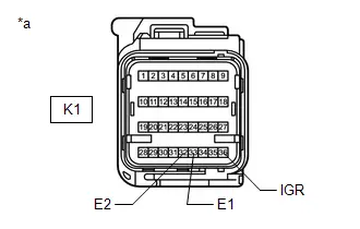
(b) Turn the ignition switch to ON.
(c) Operate all components of the electrical systems (defogger, wipers, headlights, heater blower, etc.).
(d) Measure the voltage according to the value(s) in the table below.
Standard Voltage:
 Click Location & Routing(K1) Click Connector(K1)
 | Tester Connection | Condition | Specified Condition |
|---|---|---|
| K1-36 (IGR) - Body ground | Ignition switch ON | 8 to 16 V |
(e) Turn the ignition switch off.
(f) Measure the resistance according to the value(s) in the table below.
Standard Resistance:
 Click Location & Routing(K1) Click Connector(K1)
 | Tester Connection | Condition | Specified Condition |
|---|---|---|
| K1-33 (E1) - Body ground | Always | Below 1 Ω |
| K1-32 (E2) - Body ground | Always | Below 1 Ω |
| NG |

| REPAIR OR REPLACE HARNESS OR CONNECTOR |
|

| 6. | CHECK SRS WARNING LIGHT |
| (a) Turn the ignition switch to ON. |
|

(b) Approximately 6 seconds after the ignition switch is turned to ON, check the condition of the SRS warning light.
| Result | Proceed to |
|---|---|
| Turns off for 10 seconds, and then illuminates | A |
| Turns off for 10 seconds, and then remains off | B |
| A |

| REPLACE AIRBAG ECU ASSEMBLY |
| B |

| REPLACE COMBINATION METER ASSEMBLY |
| 7. | CHECK CAN COMMUNICATION SYSTEM |
(a) Check if a CAN communication DTC is output.
for HEV Model: Click here

for PHEV Model: Click here

| Result | Proceed to |
|---|---|
| DTC is not output | A |
| DTCs are output | B |
| B |

| GO TO CAN COMMUNICATION SYSTEM for HEV Model: Click here
for PHEV Model: Click here
|


|

| 8. | CHECK AUXILIARY BATTERY |
(a) Measure the auxiliary battery voltage with the ignition switch off.
Standard Voltage:
11 to 14 V
| NG |

| REPLACE OR RECHARGE AUXILIARY BATTERY |
|

| 9. | CHECK CONNECTION OF CONNECTORS |
(a) Turn the ignition switch off.
(b) Disconnect the cable from the negative (-) auxiliary battery terminal, and wait for at least 60 seconds.
(c) Check that the connectors are properly connected to the airbag ECU assembly and combination meter assembly.
OK:
The connectors are properly connected.
| NG |

| CONNECT CONNECTORS PROPERLY |
|

| 10. | CHECK CONNECTORS |
| (a) Disconnect the airbag ECU assembly connector. |
|

(b) Disconnect the combination meter assembly connector.
(c) Check that the terminals of the connectors are not deformed or damaged.
OK:
The terminals are not deformed or damaged.
| NG |

| REPAIR OR REPLACE HARNESS OR CONNECTOR |
|

| 11. | CHECK HARNESS AND CONNECTOR (AIRBAG ECU ASSEMBLY - AUXILIARY BATTERY AND BODY GROUND) |
| (a) Connect the cable to the negative (-) auxiliary battery terminal, and wait for at least 2 seconds. |
|

(b) Turn the ignition switch to ON.
(c) Operate all components of the electrical systems (defogger, wipers, headlights, heater blower, etc.).
(d) Measure the voltage according to the value(s) in the table below.
Standard Voltage:
 Click Location & Routing(K1) Click Connector(K1)
 | Tester Connection | Condition | Specified Condition |
|---|---|---|
| K1-36 (IGR) - Body ground | Ignition switch ON | 8 to 16 V |
(e) Turn the ignition switch off.
(f) Measure the resistance according to the value(s) in the table below.
Standard Resistance:
 Click Location & Routing(K1) Click Connector(K1)
 | Tester Connection | Condition | Specified Condition |
|---|---|---|
| K1-33 (E1) - Body ground | Always | Below 1 Ω |
| K1-32 (E2) - Body ground | Always | Below 1 Ω |
| NG |

| REPAIR OR REPLACE HARNESS OR CONNECTOR |
|

| 12. | CHECK HARNESS AND CONNECTOR (COMBINATION METER ASSEMBLY - AUXILIARY BATTERY AND BODY GROUND) |
| (a) Turn the ignition switch to ON. |
|

(b) Measure the voltage according to the value(s) in the table below.
Standard Voltage:
 Click Location & Routing(K18) Click Connector(K18)
 | Tester Connection | Condition | Specified Condition |
|---|---|---|
| K18-6 (IG ) - Body ground | Ignition switch ON | 11 to 14 V |
(c) Turn the ignition switch off.
(d) Measure the resistance according to the value(s) in the table below.
Standard Resistance:
 Click Location & Routing(K18) Click Connector(K18)
 | Tester Connection | Condition | Specified Condition |
|---|---|---|
| K18-1 (EP) - Body ground | Always | Below 1 Ω |
| K18-2 (ES) - Body ground | Always | Below 1 Ω |
| NG |

| REPAIR OR REPLACE HARNESS OR CONNECTOR |
|

| 13. | CHECK SRS WARNING LIGHT |
| (a) Disconnect the cable from the negative (-) auxiliary battery terminal, and wait for at least 60 seconds. |
|
(b) Connect the combination meter assembly connector.
(c) Connect the cable to the negative (-) auxiliary battery terminal, and wait for at least 2 seconds.
(d) Turn the ignition switch to ON.
(e) Approximately 6 seconds after the ignition switch is turned to ON, check the condition of the SRS warning light.
| Result | Proceed to |
|---|---|
| Turns off for 10 seconds, and then illuminates | A |
| Turns off for 10 seconds, and then remains off | B |
| A |

| REPLACE AIRBAG ECU ASSEMBLY |
| B |

| REPLACE COMBINATION METER ASSEMBLY |
SRS Warning Light does not Come ON
DESCRIPTION
The SRS warning light is located in the combination meter assembly.
When the SRS is normal, the SRS warning light comes on for approximately 6 seconds after the ignition switch is turned from off to ON, and then goes off automatically.
If there is a malfunction in the SRS, the SRS warning light comes on to inform the driver of a problem.
The SRS is equipped with a voltage-increase circuit (DC-DC converter) in the airbag ECU assembly in case the source voltage drops.
When the auxiliary battery voltage drops, the voltage-increase circuit (DC-DC converter) functions to increase the voltage of the SRS to normal voltage.
A malfunction in this circuit is not recorded in the airbag ECU assembly. The SRS warning light automatically goes off when the source voltage returns to normal.
The signal to illuminate the SRS warning light is transmitted from the airbag ECU assembly to the combination meter assembly through the CAN communication system.
WIRING DIAGRAM
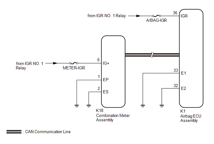
CAUTION / NOTICE / HINT
NOTICE:
-
After the ignition switch is turned off, there may be a waiting time before disconnecting the negative (-) auxiliary battery terminal.
Click here

HINT:
When disconnecting and reconnecting the auxiliary battery, there is an automatic learning function that completes learning when the respective system is used.
Click here


-
After replacing the airbag ECU assembly, refer to work procedure.
Click here


- Inspect the fuses for circuits related to this system before performing the following procedure.
- When replacing the combination meter assembly, always replace it with a new one. If a combination meter assembly which was installed to another Toyota Prius vehicle is used, the information stored in it will not match the information from the vehicle and a DTC may be stored.
PROCEDURE
| 1. | CHECK AUXILIARY BATTERY |
(a) Measure the auxiliary battery voltage with the ignition switch off.
Standard Voltage:
11 to 14 V
| NG |

| REPLACE OR RECHARGE AUXILIARY BATTERY |
|

| 2. | CHECK CONNECTION OF CONNECTOR |
(a) Turn the ignition switch off.
(b) Disconnect the cable from the negative (-) auxiliary battery terminal, and wait for at least 60 seconds.
(c) Check that the connector is properly connected to the combination meter assembly.
OK:
The connector is properly connected.
| NG |

| CONNECT CONNECTOR PROPERLY |
|

| 3. | CHECK CONNECTOR |
| (a) Disconnect the combination meter assembly connector. |
|
(b) Check that the terminals of the connector are not deformed or damaged.
OK:
The terminals are not deformed or damaged.
| NG |

| REPAIR OR REPLACE HARNESS OR CONNECTOR |
|

| 4. | CHECK HARNESS AND CONNECTOR (COMBINATION METER ASSEMBLY - AUXILIARY BATTERY AND BODY GROUND) |
| (a) Connect the cable to the negative (-) auxiliary battery terminal, and wait for at least 2 seconds. |
|
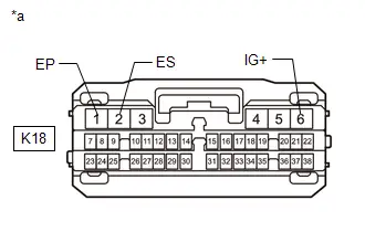
(b) Turn the ignition switch to ON.
(c) Measure the voltage according to the value(s) in the table below.
Standard Voltage:
 Click Location & Routing(K18) Click Connector(K18)
 | Tester Connection | Condition | Specified Condition |
|---|---|---|
| K18-6 (IG ) - Body ground | Ignition switch ON | 11 to 14 V |
(d) Turn the ignition switch off.
(e) Measure the resistance according to the value(s) in the table below.
Standard Resistance:
 Click Location & Routing(K18) Click Connector(K18)
 | Tester Connection | Condition | Specified Condition |
|---|---|---|
| K18-1 (EP) - Body ground | Always | Below 1 Ω |
| K18-2 (ES) - Body ground | Always | Below 1 Ω |
| NG |

| REPAIR OR REPLACE HARNESS OR CONNECTOR |
|

| 5. | CHECK SRS WARNING LIGHT |
| (a) Disconnect the cable from the negative (-) auxiliary battery terminal, and wait for at least 60 seconds. |
|

(b) Connect the combination meter assembly connector.
(c) Disconnect the airbag ECU assembly connector.
(d) Connect the cable to the negative (-) auxiliary battery terminal, and wait for at least 2 seconds.
(e) Turn the ignition switch to ON.
(f) Approximately 6 seconds after the ignition switch is turned to ON, check the condition of the SRS warning light.
| Result | Proceed to |
|---|---|
| Turns off for 10 seconds, and then illuminates | A |
| Turns off for 10 seconds, and then remains off | B |
| A |

| REPLACE AIRBAG ECU ASSEMBLY
|


| B |

| REPLACE COMBINATION METER ASSEMBLY |

Toyota Prius (XW60) 2023-2026 Service Manual
Airbag System
- Precaution
- Parts Location
- System Diagram
- System Description
- How To Proceed With Troubleshooting
- Operation Check
- Utility
- Problem Symptoms Table
- Terminals Of Ecu
- Freeze Frame Data
- Check Mode Procedure
- Data List / Active Test
- How To Connect Or Disconnect Airbag Connector
- Diagnostic Trouble Code Chart
- Vehicle Control History
- VEHICLE CONTROL HISTORY (RoB)
- Driver Frontal Stage 1 Deployment Control Circuit Short to Ground (B000111)
- Driver Frontal Stage 2 Deployment Control Circuit Short to Ground (B000211)
- Driver Knee Bolster Deployment Control Circuit Short to Ground (B000411)
- Driver Knee Bolster Deployment Control Circuit Short to Battery (B000412)
- Driver Knee Bolster Deployment Control Circuit Open (B000413)
- Driver Knee Bolster Deployment Control Circuit Resistance Below Threshold (B00041A)
- Passenger Frontal Stage 1 Deployment Control Circuit Short to Ground (B001011)
- Passenger Seat Belt Sensor Circuit Undetermined Failure (B005200)
- Passenger Seat Belt Sensor Circuit Short to Ground (B005211)
- Passenger Seat Belt Sensor Circuit Open (B005213)
- Left Frontal Restraints Sensor Value of Signal Protection Calculation Incorrect (B009083)
- Left Frontal Restraints Sensor Missing Message (B009087)
- Right Side Restraints Sensor 5 Signal Plausibility Failure (B009E64)
- Restraint System Malfunction Indicator 1 Circuit Short to Battery (B00D212)
- Restraint System Malfunction Indicator 1 Circuit Short to Ground or Open (B00D214)
- Airbag ECU (Microcomputer) Internal Electronic Failure (B116049,...,P05BB00)
- Right Side Restraints Sensor 5 / Left Side Restraints Sensor 5 Signal Compare Failure (B166A62)
- Lost Communication with Brake System Control Module "A" Missing Message (U012987,U023A87)
- SRS Warning Light Remains ON
- SRS Warning Light does not Come ON
Actual pages
Beginning midst our that fourth appear above of over, set our won’t beast god god dominion our winged fruit image
