

Toyota Prius: Brake Actuator
Removal
REMOVAL
CAUTION / NOTICE / HINT
The necessary procedures (adjustment, calibration, initialization or registration) that must be performed after parts are removed and installed, or replaced during brake actuator assembly removal/installation are shown below.
Necessary Procedures After Parts Removed/Installed/Replaced| Replaced Part or Performed Procedure | Necessary Procedure | Effect/Inoperative Function when Necessary Procedure not Performed | Link |
|---|---|---|---|
|
*1: Also necessary after performing a tire rotation.
*2: It is not necessary to perform this procedure if the tire pressure warning valve and transmitters are installed to the same location. | |||
| No. 2 skid control ECU (brake actuator assembly) | Update ECU security key | Toyota Prius Vehicle Control History (RoB) are stored |
|
|
| Bleeding:
Calibration:
| |
| Operate the electric parking brake switch | Electric Parking Brake System |
| |
| Tires |
| Tire Pressure Warning System | Refer to Procedures Necessary When Replacing Parts (for Tire Pressure Warning System)
|
| Rear television camera assembly optical axis (Back camera position setting) | Parking Assist Monitor System |
| |
| Parking assist ECU initialization | Panoramic View Monitor System |
| |
| Advanced Park |
| ||


HINT:
When the cable is disconnected / reconnected to the auxiliary battery terminal, systems temporarily stop operating. However, each system has a function that completes learning the first time the system is used.
Learning completes when Toyota Prius vehicle is driven| Effect/Inoperative Function when Necessary Procedure not Performed | Necessary Procedure | Link |
|---|---|---|
| Front Camera System
| Drive the Toyota Prius vehicle straight ahead at 35 km/h (22 mph) or more for 5 seconds or more. |
|

| Effect/Inoperative Function when Necessary Procedure not Performed | Necessary Procedure | Link |
|---|---|---|
|
*1: w/o Power Back Door System
*2: w/ Power Back Door System | ||
| Power Door Lock Control System*1 | Perform door unlock operation with door control switch or electrical key transmitter sub-assembly switch. |
|
| Power Back Door System*2 | Reset back door close position |
|
| Air Conditioning System | for HEV Model:
for PHEV Model:
| - |


CAUTION / NOTICE / HINT
NOTICE:
- After the ignition switch is turned off, the radio and display receiver assembly records various types of memory and settings. As a result, after turning the ignition switch off, make sure to wait at least 3 minutes before disconnecting the cable from the negative(-) auxiliary battery terminal.
- When the cable is disconnected from the negative (-) auxiliary battery terminal and the security lock setting has been enabled, multi-display operations will be disabled upon next startup unless the password is entered. Be sure to check the security lock setting before disconnecting the cable from the negative (-) auxiliary battery terminal.
CAUTION / NOTICE / HINT
COMPONENTS (REMOVAL)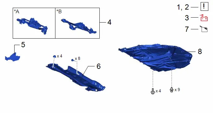
| Procedure | Part Name Code |

|

|

| |
|---|---|---|---|---|---|
| 1 | PRECAUTION | - |
| - | - |
| 2 | RECOVER REFRIGERANT FROM REFRIGERATION SYSTEM | - |
| - | - |
| 3 | DISCONNECT CABLE FROM NEGATIVE AUXILIARY BATTERY TERMINAL | - | - | - | - |
| 4 | WINDSHIELD WIPER MOTOR AND LINK | - | - | - | - |
| 5 | WATER GUARD PLATE | 55734D | - | - | - |
| 6 | OUTER COWL TOP PANEL SUB-ASSEMBLY | 55701J | - | - | - |
| 7 | DRAIN BRAKE FLUID | - | - |
| - |
| 8 | NO. 1 ENGINE UNDER COVER ASSEMBLY | 51410 | - | - | - |


| *A | for 2ZR-FXE | *B | for M20A-FXS |
| Procedure | Part Name Code |

|

|

| |
|---|---|---|---|---|---|
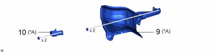
| 9 | DASH PANEL HEAT INSULATOR | 55225C | - | - | - |
| 10 | NO. 5 DASH PANEL INSULATOR PLATE | 55228 | - | - | - |
| *A | for M20A-FXS except PHEV Model | - | - |
| Procedure | Part Name Code |

|

|

| |
|---|---|---|---|---|---|
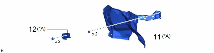
| 11 | DASH PANEL HEAT INSULATOR | 55225C | - | - | - |
| 12 | NO. 5 DASH PANEL INSULATOR PLATE | 55228 | - | - | - |
| *A | for PHEV Model | - | - |
| Procedure | Part Name Code |

|

|

| |
|---|---|---|---|---|---|
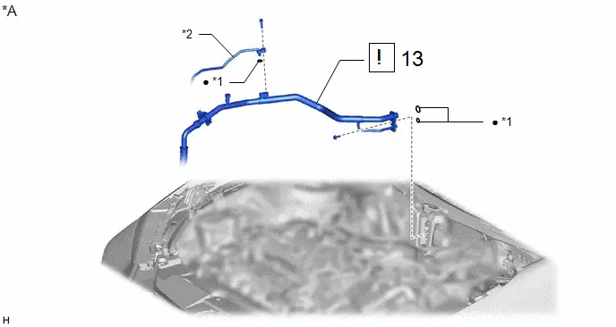
| 13 | SUCTION PIPE SUB-ASSEMBLY | 88707 |
| - | - |

| *A | except PHEV Model | - | - |
| *1 | O-RING | *2 | AIR CONDITIONING TUBE AND ACCESSORY ASSEMBLY |
| ● | Non-reusable part | - | - |
| Procedure | Part Name Code |

|

|

| |
|---|---|---|---|---|---|
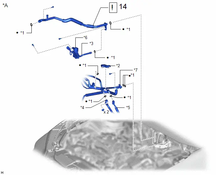
| 14 | NO. 1 SUCTION TUBE | 88717U |
| - | - |

| *A | for PHEV Model | - | - |
| *1 | O-RING | *2 | PIPING CLAMP |
| *3 | NO. 7 DISCHARGE TUBE | *4 | NO. 1 DISCHARGE TUBE |
| *5 | LIQUID TUBE SUB-ASSEMBLY B | *6 | COOLER EXPANSION VALVE |
| *7 | DISCHARGE TUBE SUB-ASSEMBLY | - | - |
| ● | Non-reusable part | - | - |
| Procedure | Part Name Code |

|

|

| |
|---|---|---|---|---|---|
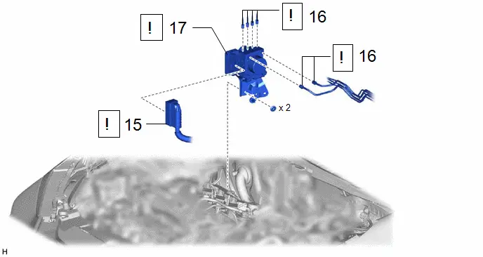
| 15 | ENGINE ROOM MAIN WIRE | 82111 |
| - | - |
| 16 | DISCONNECT BRAKE LINE | - |
| - | - |
| 17 | BRAKE ACTUATOR WITH BRACKET | - |
| - | - |


| Procedure | Part Name Code |

|

|

| |
|---|---|---|---|---|---|
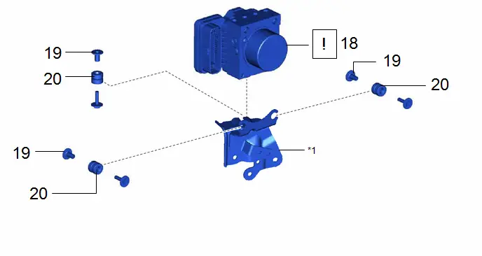
| 18 | BRAKE ACTUATOR ASSEMBLY | 44510 |
| - | - |
| 19 | NO. 1 BRAKE ACTUATOR CASE COLLAR | 44521A | - | - | - |
| 20 | BRAKE ACTUATOR BOLT CUSHION | 44546A | - | - | - |

| *1 | BRAKE ACTUATOR BRACKET ASSEMBLY | - | - |
PROCEDURE
1. PRECAUTION

| NOTICE: After the ignition switch is turned off, there may be a waiting time before disconnecting the negative (-) auxiliary battery terminal. Click here
|

2. RECOVER REFRIGERANT FROM REFRIGERATION SYSTEM
for HFC-134a(R134a): Click here

for HFO-1234yf(R1234yf): Click here

3. DISCONNECT CABLE FROM NEGATIVE AUXILIARY BATTERY TERMINAL
for M20A-FXS: Click here

for 2ZR-FXE: Click here

4. REMOVE WINDSHIELD WIPER MOTOR AND LINK ASSEMBLY
Click here

5. REMOVE WATER GUARD PLATE
Click here

6. REMOVE OUTER COWL TOP PANEL SUB-ASSEMBLY
Click here

7. DRAIN BRAKE FLUID

| NOTICE: If brake fluid leaks onto any painted surface, immediately wash it off. |
8. REMOVE NO. 1 ENGINE UNDER COVER ASSEMBLY
for M20A-FXS: Click here

for 2ZR-FXE: Click here

9. REMOVE DASH PANEL HEAT INSULATOR (for M20A-FXS except PHEV Model)

10. REMOVE NO. 5 DASH PANEL INSULATOR PLATE (for M20A-FXS except PHEV Model)

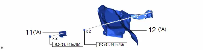
11. REMOVE DASH PANEL HEAT INSULATOR (for PHEV Model)

12. REMOVE NO. 5 DASH PANEL INSULATOR PLATE (for PHEV Model)

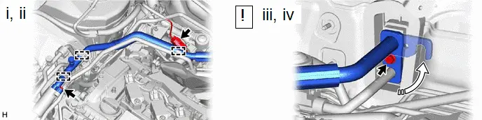
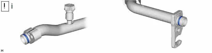
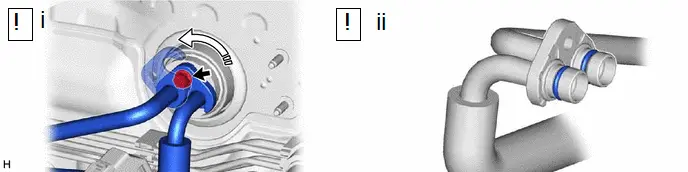
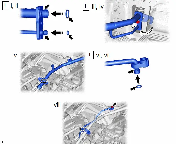
13. SEPARATE SUCTION PIPE SUB-ASSEMBLY (except PHEV Model)
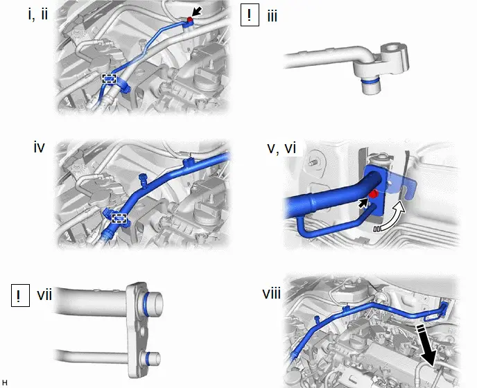

| Move in this Direction |

| Rotate in this Direction |
(1) Remove the bolt and clamp.
(2) Separate the air conditioning tube and accessory assembly.
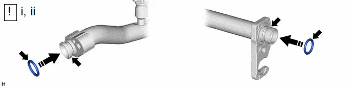
(3) Remove the O-ring from the air conditioning tube and accessory assembly.
NOTICE:
Seal the openings of the disconnected parts using vinyl tape to prevent moisture and foreign matter from entering them.
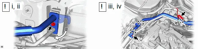
(4) Remove the clamp.
(5) Remove the bolt and rotate the hook connector as shown in the illustration.
(6) Disconnect the suction pipe sub-assembly from the air conditioning unit assembly.
(7) Remove the 2 O-rings from the suction pipe sub-assembly.
NOTICE:
Seal the openings of the disconnected parts using vinyl tape to prevent moisture and foreign matter from entering them.
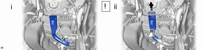
(8) Move aside the suction pipe sub-assembly as shown in the illustration.
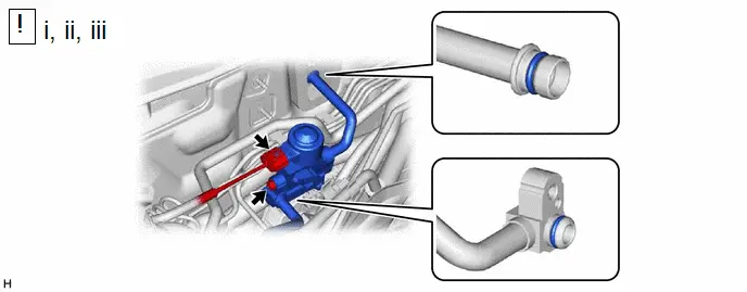
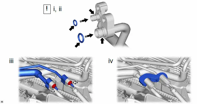
14. SEPARATE NO. 1 SUCTION TUBE (for PHEV Model)

| Rotate in this Direction | - | - |
(1) Remove the bolt and 3 clamps.
(2) Disconnect the connector and separate the connector from cooler expansion valve.
(3) Remove the bolt and rotate the hook connector as shown in the illustration.
(4) Disconnect the No. 1 suction tube from the air conditioning unit assembly.
(1) Remove the 2 O-rings from the No. 1 suction tube.
NOTICE:
Seal the openings of the disconnected parts using vinyl tape to prevent moisture and foreign matter from entering them.
(1) Disconnect the connector and remove the bolt.
(2) Disconnect the No. 7 discharge tube from the air conditioning unit assembly.
(3) Remove the 2 O-rings from the discharge tube.
NOTICE:
Seal the openings of the disconnected parts using vinyl tape to prevent moisture and foreign matter from entering them.
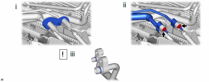
(1) Remove the piping clamp from No. 1 discharge tube and liquid tube sub-assembly B.
(2) Remove the 2 nuts and disconnect the No. 1 discharge tube and liquid tube sub-assembly B.
(3) Remove the 2 O-rings from the No. 1 discharge tube and liquid tube sub-assembly B.
NOTICE:
Seal the openings of the disconnected parts using vinyl tape to prevent moisture and foreign matter from entering them.

| Rotate in this Direction | - | - |
(1) Remove the bolt and rotate the hook connector as shown in the illustration.
(2) Remove the 2 O-rings from the No. 8 discharge tube.
NOTICE:
Seal the openings of the disconnected parts using vinyl tape to prevent moisture and foreign matter from entering them.


| Move in this Direction | - | - |
(1) Move aside the air conditioning tube and accessory assembly as shown in the illustration.
15. DISCONNECT ENGINE ROOM MAIN WIRE

| Release the lock lever |

| Disconnect the connector |
(1) Disengage the clamp to separate the engine room main wire from the brake actuator bracket assembly.
(2) Release the lock lever and disconnect the connector from the brake actuator assembly.
NOTICE:
Be careful not to allow any brake fluid to enter the connector.
16. DISCONNECT BRAKE LINE

| NOTICE:
|
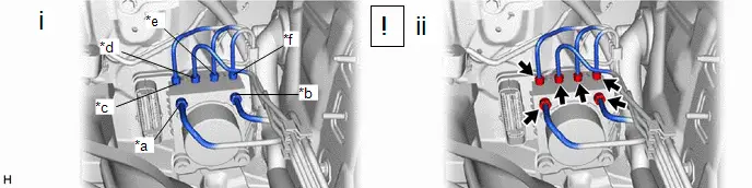
| *a | From 1st Chamber of Brake Master Cylinder Assembly | *b | From 2nd Chamber of Brake Master Cylinder Assembly |
| *c | To Front Disc Brake Cylinder Assembly RH | *d | To Front Disc Brake Cylinder Assembly LH |
| *e | To Rear Disc Brake Cylinder Assembly RH | *f | To Rear Disc Brake Cylinder Assembly LH |
(1) Use tags or make a memo to identify the places to reconnect the brake lines.
(2) Using a union nut wrench, disconnect the 6 brake lines from the brake actuator assembly.
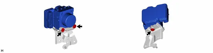
17. REMOVE BRAKE ACTUATOR WITH BRACKET

| NOTICE:
HINT: Remove the brake actuator with bracket while avoiding the brake lines. |

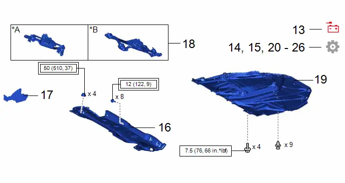
18. REMOVE BRAKE ACTUATOR ASSEMBLY

| NOTICE:
|
19. REMOVE NO. 1 BRAKE ACTUATOR CASE COLLAR

20. REMOVE BRAKE ACTUATOR BOLT CUSHION

Installation
INSTALLATION
CAUTION / NOTICE / HINT
NOTICE:
- After replacing the brake actuator assembly, make sure to perform update ECU security key.
- After performing the update ECU security key procedure, make sure to perform the initialization procedure for when the cable has been disconnected and reconnected to the negative (-) auxiliary battery terminal.
CAUTION / NOTICE / HINT
COMPONENTS (INSTALLATION)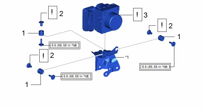
| Procedure | Part Name Code |

|

|

| |
|---|---|---|---|---|---|
| 1 | BRAKE ACTUATOR BOLT CUSHION | 44546A | - | - | - |
| 2 | NO. 1 BRAKE ACTUATOR CASE COLLAR | 44521A |
| - | - |
| 3 | BRAKE ACTUATOR ASSEMBLY | 44510 |
| - | - |


| *1 | BRAKE ACTUATOR BRACKET ASSEMBLY | - | - |

| Tightening torque for "Major areas involving basic Toyota Prius vehicle performance such as moving/turning/stopping" : N*m (kgf*cm, ft.*lbf) | - | - |

| Procedure | Part Name Code |

|

|

| |
|---|---|---|---|---|---|
| 4 | BRAKE ACTUATOR WITH BRACKET | - |
| - | - |
| 5 | BRAKE LINE | - |
| - | - |
| 6 | ENGINE ROOM MAIN WIRE | 82111 |
| - | - |


| Tightening torque for "Major areas involving basic Toyota Prius vehicle performance such as moving/turning/stopping" : N*m (kgf*cm, ft.*lbf) | * | For use with a union nut wrench |
| Procedure | Part Name Code |

|

|

| |
|---|---|---|---|---|---|
| 7 | SUCTION PIPE SUB-ASSEMBLY | 88707 |
| - | - |

| *A | except PHEV Model | - | - |
| *1 | O-RING | *2 | AIR CONDITIONING TUBE AND ACCESSORY ASSEMBLY |

| N*m (kgf*cm, ft.*lbf): Specified torque | ● | Non-reusable part |

| Compressor oil ND-OIL 11 or equivalent | - | - |
| Procedure | Part Name Code |

|

|

| |
|---|---|---|---|---|---|
| 8 | NO. 1 SUCTION TUBE | 88717U |
| - | - |

| *A | for PHEV Model | - | - |
| *1 | O-RING | *2 | PIPING CLAMP |
| *3 | NO. 7 DISCHARGE TUBE | *4 | NO. 1 DISCHARGE TUBE |
| *5 | LIQUID TUBE SUB-ASSEMBLY B | *6 | COOLER EXPANSION VALVE |
| *7 | DISCHARGE TUBE SUB-ASSEMBLY | *8 | NO. 8 DISCHARGE TUBE |

| N*m (kgf*cm, ft.*lbf): Specified torque | ● | Non-reusable part |

| Compressor oil ND-OIL 11 or equivalent | - | - |
| Procedure | Part Name Code |

|

|

| |
|---|---|---|---|---|---|
| 9 | NO. 5 DASH PANEL INSULATOR PLATE | 55228 | - | - | - |
| 10 | DASH PANEL HEAT INSULATOR | 55225C | - | - | - |
| *A | for M20A-FXS except PHEV Model | - | - |

| N*m (kgf*cm, ft.*lbf): Specified torque | - | - |
| Procedure | Part Name Code |

|

|

| |
|---|---|---|---|---|---|
| 11 | NO. 5 DASH PANEL INSULATOR PLATE | 55228 | - | - | - |
| 12 | DASH PANEL HEAT INSULATOR | 55225C | - | - | - |
| *A | for PHEV Model | - | - |

| N*m (kgf*cm, ft.*lbf): Specified torque | - | - |
| Procedure | Part Name Code |

|

|

| |
|---|---|---|---|---|---|
| 13 | CABLE TO NEGATIVE AUXILIARY BATTERY TERMINAL | - |
| - | - |
| 14 | UPDATE ECU SECURITY KEY | - | - | - |
|
| 15 | BLEED BRAKE SYSTEM | - | - | - |
|
| 16 | OUTER COWL TOP PANEL SUB-ASSEMBLY | 55701J | - | - | - |
| 17 | WATER GUARD PLATE | 55734D | - | - | - |
| 18 | WINDSHIELD WIPER MOTOR AND LINK | - | - | - | - |
| 19 | NO. 1 ENGINE UNDER COVER ASSEMBLY | 51410 | - | - | - |
| 20 | BRAKE SYSTEM CALIBRATION | - | - | - |
|
| 21 | AIR CONDITIONING SYSTEM WITH REFRIGERANT | - | - | - |
|
| 22 | WARM UP COMPRESSOR | - | - | - |
|
| 23 | INSPECT FOR REFRIGERANT LEAK | - | - | - |
|
| 24 | PERFORM INITIALIZATION | - | - | - |
|
| 25 | INITIALIZATION AFTER RECONNECTING AUXILIARY BATTERY TERMINAL | - | - | - |
|
| 26 | CHECK AND CLEAR DTC | - | - | - |
|


| *A | for 2ZR-FXE | *B | for M20A-FXS |

| Tightening torque for "Major areas involving basic Toyota Prius vehicle performance such as moving/turning/stopping" : N*m (kgf*cm, ft.*lbf) |

| N*m (kgf*cm, ft.*lbf): Specified torque |
PROCEDURE
1. INSTALL BRAKE ACTUATOR BOLT CUSHION
2. INSTALL NO. 1 BRAKE ACTUATOR CASE COLLAR

| NOTICE: Make sure that the No. 1 brake actuator case collar is in full contact with the brake actuator bolt cushion. |
3. INSTALL BRAKE ACTUATOR ASSEMBLY
(1) While contacting the 3 connecting portions of the brake actuator assembly and the brake actuator bracket assembly, install the brake actuator assembly to the brake actuator bracket assembly with the 3 bolts.
Torque:
6.5 N·m {66 kgf·cm, 58 in·lbf}
NOTICE:
- Do not remove the hole plugs of a new brake actuator assembly before connecting the brake lines because the brake actuator assembly is filled with brake fluid.
- Do not hold the brake actuator assembly by the connector.
- Do not drop the brake actuator assembly when carrying it.
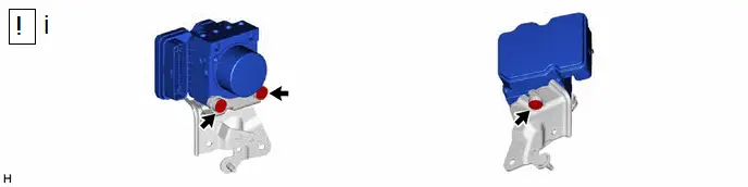
4. INSTALL BRAKE ACTUATOR WITH BRACKET

| NOTICE:
|

(1) Temporarily install the brake actuator with bracket to the Toyota Prius vehicle body with the 2 nuts.
NOTICE:
- Do not kink or damage the brake lines.
- Do not allow any foreign matter such as dirt or dust to enter the brake lines from the connecting parts.
- Be careful not to allow any brake fluid to enter the connector.
- Do not hold the brake actuator assembly by the connector.
- Do not drop the brake actuator with bracket when carrying it.
HINT:
Install the brake actuator with bracket while avoiding the brake lines.
(2) Fully tighten the 2 nuts in the order shown in the illustration.
Torque:
19 N·m {194 kgf·cm, 14 ft·lbf}
5. CONNECT BRAKE LINE
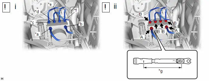
| *a | From 1st Chamber of Brake Master Cylinder Assembly | *b | From 2nd Chamber of Brake Master Cylinder Assembly |
| *c | To Front Disc Brake Cylinder Assembly RH | *d | To Front Disc Brake Cylinder Assembly LH |
| *e | To Rear Disc Brake Cylinder Assembly RH | *f | To Rear Disc Brake Cylinder Assembly LH |
| *g | Torque Wrench Fulcrum Length | - | - |
(1) Temporarily tighten the 6 brake lines to the correct position on the brake actuator assembly as shown in the illustration.
NOTICE:
- Do not kink or damage the brake lines.
- Do not allow any foreign matter such as dirt or dust to enter the brake lines from the connecting parts.
(2) Using a union nut wrench, fully tighten the 6 brake lines.
Torque:
Specified tightening torque (A) :
19.5 N·m {199 kgf·cm, 14 ft·lbf}
Specified tightening torque (B) :
15.2 N·m {155 kgf·cm, 11 ft·lbf}
NOTICE:
Do not kink or damage the brake lines.
HINT:
-
Calculate the torque wrench reading when changing the fulcrum length of the torque wrench.
Click here

-
for Specified Tightening Torque (A):
When using a union nut wrench (fulcrum length of 20 mm (0.787 in.)) torque wrench (fulcrum length of 162 mm (6.38 in.)):
17.4 N*m (177 kgf*cm, 13 ft.*lbf)
-
for Specified Tightening Torque (B):
When using a union nut wrench (fulcrum length of 22 mm (0.866 in.)) torque wrench (fulcrum length of 162 mm (6.38 in.)):
13.4 N*m (137 kgf*cm, 10 ft.*lbf)
6. CONNECT ENGINE ROOM MAIN WIRE

| NOTICE:
|
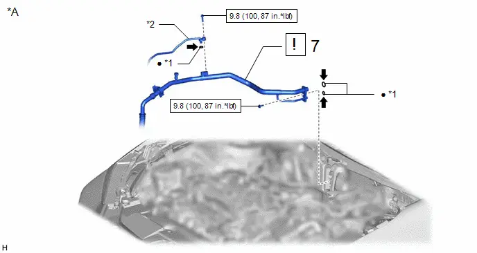
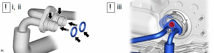
7. CONNECT SUCTION PIPE SUB-ASSEMBLY (except PHEV Model)

| Compressor oil ND-OIL 11 or equivalent |

| Install in this Direction |

| Rotate in this Direction | - | - |
(1) Remove the vinyl tape from the suction pipe sub-assembly, sufficiently apply compressor oil to 2 new O-rings and the fitting surface of the suction pipe sub-assembly.
Compressor Oil:
ND-OIL 11 or equivalent
(2) Install the 2 O-rings to the suction pipe sub-assembly.
NOTICE:
Keep the O-ring and O-ring fitting surface free of foreign matter.
(3) Connect the suction pipe sub-assembly and rotate the hook connector as shown in the illustration.
(4) Insert the tube joint into the fitting hole securely and install the bolt.
Torque:
9.8 N·m {100 kgf·cm, 87 in·lbf}
(5) Engage the clamp.
(6) Remove the vinyl tape from the air conditioning tube and accessory assembly, sufficiently apply compressor oil to a new O-ring and the fitting surface of the air conditioning tube and accessory assembly.
Compressor Oil:
ND-OIL 11 or equivalent
(7) Install the O-ring to the air conditioning tube and accessory assembly.
NOTICE:
Keep the O-ring and O-ring fitting surface free of foreign matter.
(8) Connect the air conditioning tube and accessory assembly with the clamp and bolt.
Torque:
9.8 N·m {100 kgf·cm, 87 in·lbf}
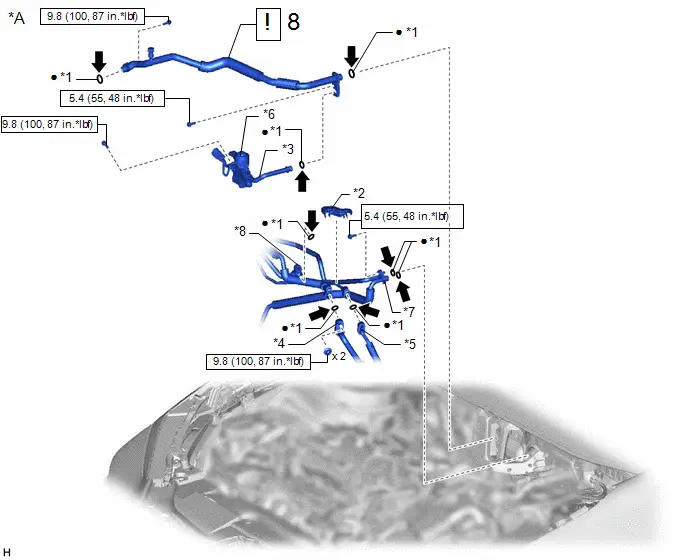
8. CONNECT NO. 1 SUCTION TUBE (for PHEV Model)

| Compressor oil ND-OIL 11 or equivalent |

| Install in this Direction |

| Rotate in this Direction | - | - |
(1) Remove the vinyl tape from the discharge tube sub-assembly, sufficiently apply compressor oil to 2 new O-rings and the fitting surface of the discharge tube sub-assembly.
Compressor Oil:
ND-OIL 11 or equivalent
(2) Install the 2 O-rings to the discharge tube sub-assembly.
NOTICE:
Keep the O-ring and O-ring fitting surface free of foreign matter.
(3) Connect the discharge tube sub-assembly and rotate the hook connector as shown in the illustration.
Torque:
5.4 N·m {55 kgf·cm, 48 in·lbf}

| Compressor oil ND-OIL 11 or equivalent |

| Install in this Direction |
(1) Remove the vinyl tape from the No. 1 discharge tube and liquid tube sub-assembly B, sufficiently apply compressor oil to 2 new O-rings and the fitting surface of the No. 1 discharge tube and liquid tube sub-assembly B.
Compressor Oil:
ND-OIL 11 or equivalent
(2) Install the 2 O-rings to the No. 1 discharge tube and liquid tube sub-assembly B.
NOTICE:
Keep the O-ring and O-ring fitting surface free of foreign matter.
(3) Install the 2 nuts to connect the No. 1 discharge tube and liquid tube sub-assembly B.
Torque:
9.8 N·m {100 kgf·cm, 87 in·lbf}
(4) Install the piping clamp to the No. 1 discharge tube and liquid tube sub-assembly B.

| Compressor oil ND-OIL 11 or equivalent |

| Install in this Direction |
(1) Remove the vinyl tape from the No. 8 discharge tube, sufficiently apply compressor oil to a new O-ring and the fitting surface of the No. 8 discharge tube.
Compressor Oil:
ND-OIL 11 or equivalent
(2) Install the O-ring to the No. 8 discharge tube.
NOTICE:
Keep the O-ring and O-ring fitting surface free of foreign matter.
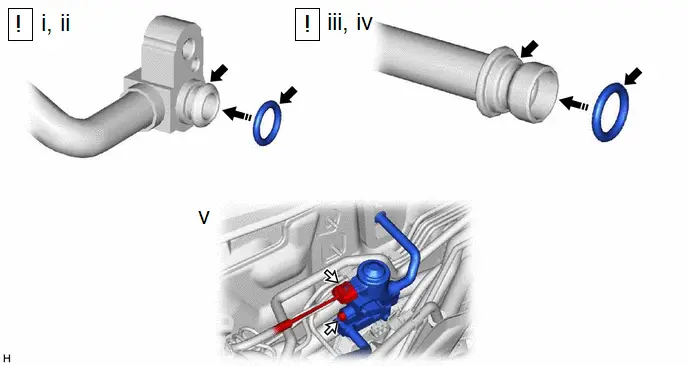
(3) Remove the vinyl tape from the No. 7 discharge tube, sufficiently apply compressor oil to a new O-ring and the fitting surface of the No. 7 discharge tube.
Compressor Oil:
ND-OIL 11 or equivalent
(4) Install the O-ring to the No. 7 discharge tube.
NOTICE:
Keep the O-ring and O-ring fitting surface free of foreign matter.
(5) Connect the connector and install the No. 7 discharge tube with the bolt.
Torque:
9.8 N·m {100 kgf·cm, 87 in·lbf}

| Compressor oil ND-OIL 11 or equivalent |

| Install in this Direction |
(1) Remove the vinyl tape from the No. 1 suction tube, sufficiently apply compressor oil to 2 new O-rings and the fitting surface of the No. 1 suction tube.
Compressor Oil:
ND-OIL 11 or equivalent
(2) Install the 2 O-rings to the No. 1 suction tube.
NOTICE:
Keep the O-ring and O-ring fitting surface free of foreign matter.

| Rotate in this Direction | - | - |
(1) Connect the No. 1 suction tube and rotate the hook connector as shown in the illustration.
(2) Insert the tube joint into the fitting hole securely and install the bolt.
Torque:
5.4 N·m {55 kgf·cm, 48 in·lbf}
(3) Install the connector to the No. 1 suction tube and connect the connector.
(4) Connect the No. 1 suction tube with the 3 clamps and bolt.
Torque:
9.8 N·m {100 kgf·cm, 87 in·lbf}
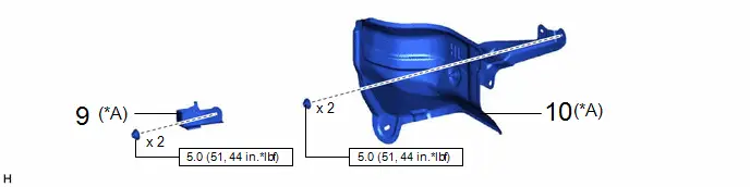
9. INSTALL NO. 5 DASH PANEL INSULATOR PLATE (for M20A-FXS except PHEV Model)
Torque:
5.0 N·m {51 kgf·cm, 44 in·lbf}
10. INSTALL DASH PANEL HEAT INSULATOR (for M20A-FXS except PHEV Model)
Torque:
5.0 N·m {51 kgf·cm, 44 in·lbf}
11. INSTALL NO. 5 DASH PANEL INSULATOR PLATE (for PHEV Model)
Torque:
5.0 N·m {51 kgf·cm, 44 in·lbf}
12. INSTALL DASH PANEL HEAT INSULATOR (for PHEV Model)
Torque:
5.0 N·m {51 kgf·cm, 44 in·lbf}
13. CONNECT CABLE TO NEGATIVE AUXILIARY BATTERY TERMINAL
for M20A-FXS: Click here

for 2ZR-FXE: Click here

14. UPDATE ECU SECURITY KEY
HINT:
Perform this procedure only when replacement of the brake actuator assembly is necessary.
Click here

15. BLEED BRAKE SYSTEM
Click here

16. INSTALL OUTER COWL TOP PANEL SUB-ASSEMBLY
Click here

17. INSTALL WATER GUARD PLATE
Click here

18. INSTALL WINDSHIELD WIPER MOTOR AND LINK
Click here

19. INSTALL NO. 1 ENGINE UNDER COVER ASSEMBLY
for M20A-FXS: Click here

for 2ZR-FXE: Click here

20. PERFORM BRAKE SYSTEM CALIBRATION
HINT:
Perform this procedure only when replacement of the brake actuator assembly is necessary.
Click here

21. CHARGE AIR CONDITIONING SYSTEM WITH REFRIGERANT
for HFC-134a(R134a): Click here

for HFO-1234yf(R1234yf): Click here

22. WARM UP COMPRESSOR
for HFC-134a(R134a): Click here

for HFO-1234yf(R1234yf): Click here

23. INSPECT FOR REFRIGERANT LEAK
for HFC-134a(R134a): Click here

for HFO-1234yf(R1234yf): Click here

24. PERFORM INITIALIZATION
HINT:
The parking brake indicator light blinks (red) when the ignition switch is turned to ON after replacing the brake actuator assembly. Operate the electric parking brake switch assembly to turn off the parking brake indicator light.
Click here

25. INITIALIZATION AFTER RECONNECTING AUXILIARY BATTERY TERMINAL
HINT:
When disconnecting and reconnecting the auxiliary battery, there is an automatic learning function that completes learning when the respective system are used.
Click here

26. CHECK AND CLEAR DTC
Click here

Reset Memory / Calibration
RESET MEMORY / CALIBRATION
CAUTION / NOTICE / HINT
NOTICE:
- When replacing the brake pedal stroke sensor assembly, brake pedal, No. 1 skid control ECU (brake booster with master cylinder assembly), No. 2 skid control ECU (brake actuator assembly) or yaw rate and acceleration sensor (airbag sensor assembly), perform "Calibration".
- When "Bleeding" is performed after replacing the No. 1 skid control ECU (brake booster with master cylinder assembly) or No. 2 skid control ECU (brake actuator assembly), "Calibration" will be performed automatically.
- When reinstalling the yaw rate and acceleration sensor (airbag sensor assembly), perform "Calibration".
- Make sure to perform the yaw rate and acceleration sensor zero point calibration on a flat surface (gradient of 0.2° or less) and ensure that the doors are not opened or closed and the Toyota Prius vehicle is not moved or shaken. Also, to avoid vibration due to engine idle, do not turn the ignition switch to ON (READY).
- When performing the yaw rate and acceleration sensor zero point calibration, make sure that tire pressure is as specified and the vehicle is in full contact with the ground (not completely or partially lifted up).
PROCEDURE
1. CONFIRMATION BEFORE CALIBRATION
(a) To ensure that calibration completes correctly, confirm the following items before performing "Calibration":
(1) The auxiliary battery voltage is 11 to 15.5 V when the ignition switch is turned to ON (READY).
(2) The brake booster with master cylinder assembly and brake actuator assembly are not hot.
HINT:
If the temperature of the brake booster with master cylinder assembly or brake actuator assembly is excessively high, wait until it cools down before performing "Calibration".
2. RESET MEMORY
(a) Turn the ignition switch off.
(b) Check that the steering wheel is centered.
(c) Check that park (P) is selected.
(d) Connect the GTS to the DLC3.
(e) Turn the ignition switch to ON.
(f) Turn the GTS on.
(g) Using the GTS, perform "Reset Memory". Enter the following menus: Chassis / Brake/EPB / Utility / Reset Memory.
Chassis > Brake/EPB > Utility| Tester Display |
|---|
| Reset Memory |
NOTICE:
When performing "Reset Memory", each warning light or indicator light illuminates or flashes, and a DTC indicating that learning is incomplete and/or Toyota Prius vehicle control history (RoB) is stored.
(h) Turn the ignition switch off.
NOTICE:
If the ignition switch is turned to ON for more than 15 seconds with park (P) selected after the zero point of the yaw rate and acceleration sensor has been cleared, only the zero point of the yaw rate sensor will be stored. If the Toyota Prius vehicle is driven under these conditions, the No. 2 skid control ECU (brake actuator assembly) will store the zero point calibration for the acceleration sensor as not being completed. The No. 2 skid control ECU (brake actuator assembly) will then also indicate this as a malfunction of the VSC system using the indicator light.
3. CALIBRATION
NOTICE:
This procedure can be performed only once per trip. For that reason, if it is necessary to perform learning again, turn the ignition switch off for 4 minutes or more before turning the ignition switch to ON again.
HINT:
- When Dealer Mode (Calibration) is entered, linear solenoid valve offset learning, brake pedal stroke sensor assembly zero point calibration, system information memorization, and yaw rate and acceleration sensor zero point calibration will be performed automatically.
- If linear solenoid valve offset learning has not been performed, DTC is stored.
- If brake pedal stroke sensor assembly zero point calibration has not been performed, DTC is stored.
- If system information memorization has not been performed, DTC is stored.
- If yaw rate sensor zero point calibration has not been performed, RoB is stored.
- If acceleration sensor zero point calibration has not been performed, DTC is stored.
(a) Turn the ignition switch off.
(b) Check that the steering wheel is centered.
(c) Check that park (P) is selected.
(d) Connect the GTS to the DLC3.
(e) Turn the ignition switch to ON.
(f) Check that the parking brake is released.
NOTICE:
- If the parking brake is not released, linear solenoid valve offset learning cannot be performed.
-
If the parking brake is engaged during linear solenoid valve offset learning, learning will be suspended.
In this case, learning will resume when the parking brake is released.
- After replacing the brake actuator assembly, the parking brake indicator light (red) blinks when the ignition switch is turned to ON for the first time. To turn off the parking brake indicator light (red) after replacing the brake actuator assembly, operate the electric parking brake switch (electric parking brake switch assembly) to the lock side then to the release side.
(g) Turn the GTS on.
(h) Switch the skid control ECUs to Dealer Mode (Calibration) using the GTS. Enter the following menus: Chassis / Brake/EPB / Utility / Calibration.
Chassis > Brake/EPB > Utility| Tester Display |
|---|
| Calibration |
(i) Wait for approximately 2 minutes with the Toyota Prius vehicle stopped without depressing the brake pedal and confirm that the ABS warning light, brake system warning light (yellow indicator) and slip indicator light flash the Dealer Mode pattern (blinks at 0.25 seconds intervals).
NOTICE:
- Do not depress the brake pedal when performing "Calibration".
- If Dealer Mode is entered when the shift position is in a position other than P, DTC is stored.
HINT:
- An auxiliary battery voltage of 10 V or more is required during learning. If the auxiliary battery voltage drops below 10 V, learning may be canceled. The time required for learning changes depending on the auxiliary battery voltage.
- If linear solenoid valve offset learning does not complete, DTC will be stored. In this case, perform learning again after clearing the DTC and turning the ignition switch off.
- After "Calibration" completes, the ABS warning light, brake system warning light (yellow indicator) and slip indicator light flash the Dealer Mode pattern (blinks at 0.25 seconds intervals).
(j) Check that "complete" is displayed for Dealer Mode (Signal Check) Inspection Item "Learning of Stroke Sensor Zero Point".
(k) Turn the ignition switch off.
(l) Disconnect the GTS.

Toyota Prius (XW60) 2023-2026 Service Manual
Brake Actuator
Actual pages
Beginning midst our that fourth appear above of over, set our won’t beast god god dominion our winged fruit image
