

Toyota Prius: Ambient Temperature Sensor
Removal
REMOVAL
CAUTION / NOTICE / HINT
The necessary procedures (adjustment, calibration, initialization or registration) that must be performed after parts are removed and installed, or replaced during thermistor assembly and lever set removal/installation are shown below.
Necessary Procedures After Parts Removed/Installed/Replaced| Replaced Part or Performed Procedure | Necessary Procedures | Effect/Inoperative Function When Necessary Procedures are not Performed | Link |
|---|---|---|---|
| *: Even when not replacing the part, it is necessary to perform the specified necessary procedures after installation. | |||
| Front bumper assembly* | Front television camera view adjustment | Panoramic View Monitor System |
|
| Advanced Park |
| ||


CAUTION / NOTICE / HINT
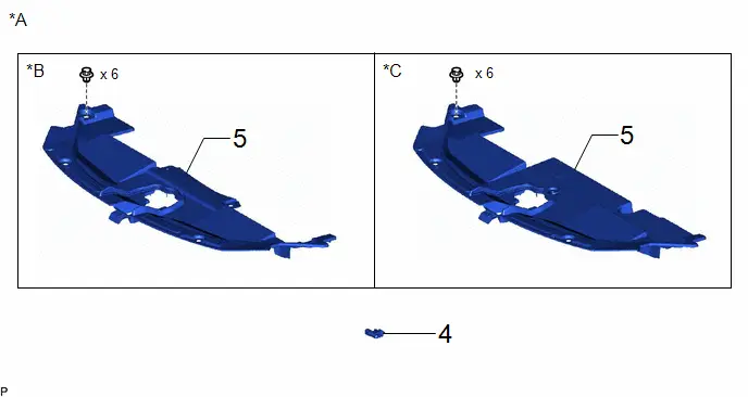
COMPONENTS (REMOVAL)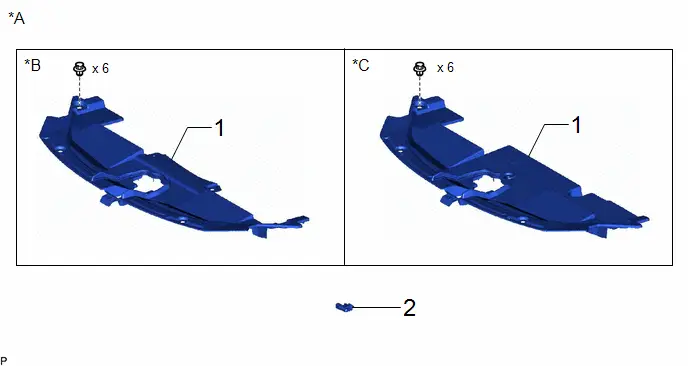
| Procedure | Part Name Code |

|

|

| |
|---|---|---|---|---|---|
| 1 | RADIATOR SUPPORT OPENING COVER | 53289A | - | - | - |
| 2 | THERMISTOR ASSEMBLY | 88790B | - | - | - |
| *A | w/o Grille Shutter | *B | for M20A-FXS |
| *C | for 2ZR-FXE | - | - |

| Procedure | Part Name Code |

|

|

| |
|---|---|---|---|---|---|
| 3 | FRONT BUMPER ASSEMBLY | - | - | - | - |
| 4 | FRONT RADIATOR SIDE AIR GUIDE PLATE LH | 16695A | - | - | - |
| 5 | THERMISTOR ASSEMBLY | 88790B | - | - | - |
| *A | w/ Grille Shutter | - | - |
PROCEDURE
1. REMOVE RADIATOR SUPPORT OPENING COVER (w/o Grille Shutter)
Click here

2. REMOVE THERMISTOR ASSEMBLY (w/o Grille Shutter)

3. REMOVE FRONT BUMPER ASSEMBLY (w/ Grille Shutter)
Click here

4. REMOVE FRONT RADIATOR SIDE AIR GUIDE PLATE LH (w/ Grille Shutter)
Click here

5. REMOVE THERMISTOR ASSEMBLY (w/ Grille Shutter)

Inspection
INSPECTION
PROCEDURE
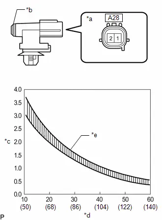
1. INSPECT THERMISTOR ASSEMBLY (for M20A-FXS)
| (a) Measure the resistance according to the value(s) in the table below. Standard Resistance:  Click Location & Routing(A28) Click Connector(A28) Click Location & Routing(A28) Click Connector(A28)
NOTICE:
HINT: As the temperature increases, the resistance decreases (see the graph). If the result is not as specified, replace the thermistor assembly. |
|
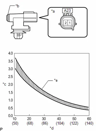
2. INSPECT THERMISTOR ASSEMBLY (for 2ZR-FXE)
| (a) Measure the resistance according to the value(s) in the table below. Standard Resistance:  Click Location & Routing(A23) Click Connector(A23) Click Location & Routing(A23) Click Connector(A23)
NOTICE:
HINT: As the temperature increases, the resistance decreases (see the graph). If the result is not as specified, replace the thermistor assembly. |
|
Installation
INSTALLATION
CAUTION / NOTICE / HINT
COMPONENTS (INSTALLATION)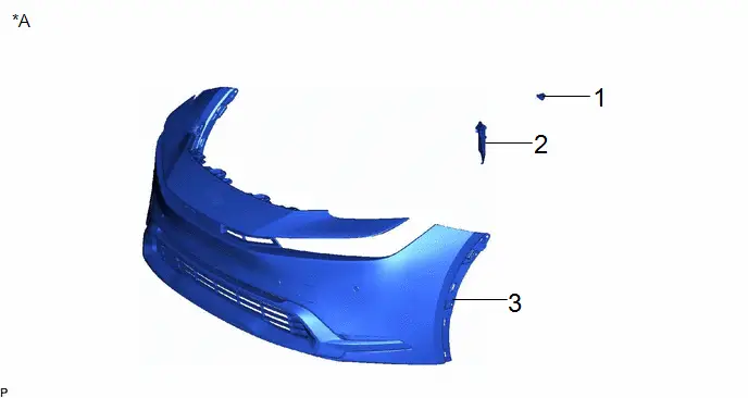
| Procedure | Part Name Code |

|

|

| |
|---|---|---|---|---|---|
| 1 | THERMISTOR ASSEMBLY | 88790B | - | - | - |
| 2 | FRONT RADIATOR SIDE AIR GUIDE PLATE LH | 16695A | - | - | - |
| 3 | FRONT BUMPER ASSEMBLY | - | - | - | - |
| *A | w/ Grille Shutter | - | - |
| Procedure | Part Name Code |

|

|

| |
|---|---|---|---|---|---|
| 4 | THERMISTOR ASSEMBLY | 88790B | - | - | - |
| 5 | RADIATOR SUPPORT OPENING COVER | 53289A | - | - | - |
| *A | w/o Grille Shutter | *B | for M20A-FXS |
| *C | for 2ZR-FXE | - | - |
PROCEDURE
1. INSTALL THERMISTOR ASSEMBLY (w/ Grille Shutter)
2. INSTALL FRONT RADIATOR SIDE AIR GUIDE PLATE LH (w/ Grille Shutter)
3. INSTALL FRONT BUMPER ASSEMBLY (w/ Grille Shutter)
Click here

4. INSTALL THERMISTOR ASSEMBLY (w/o Grille Shutter)
5. INSTALL RADIATOR SUPPORT OPENING COVER (w/o Grille Shutter)

Toyota Prius (XW60) 2023-2026 Service Manual
Ambient Temperature Sensor
Actual pages
Beginning midst our that fourth appear above of over, set our won’t beast god god dominion our winged fruit image
