

Toyota Prius: Back Door Courtesy Switch
Removal
REMOVAL
CAUTION / NOTICE / HINT
COMPONENT (REMOVAL)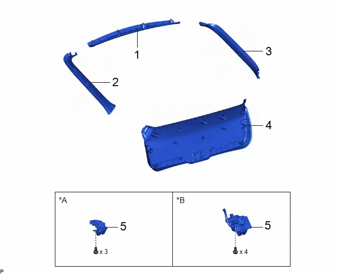
| Procedure | Part Name Code |

|

|

| |
|---|---|---|---|---|---|
| 1 | BACK DOOR UPPER TRIM PANEL ASSEMBLY | 64790B | - | - | - |
| 2 | BACK DOOR SIDE GARNISH LH | 67938A | - | - | - |
| 3 | BACK DOOR SIDE GARNISH RH | 67937B | - | - | - |
| 4 | BACK DOOR TRIM BOARD ASSEMBLY | 67750 | - | - | - |
| 5 | BACK DOOR LOCK ASSEMBLY WITH COURTESY LIGHT SWITCH | 69350P | - | - | - |
| *A | w/ Power Back Door | *B | w/ Power Back Door |
PROCEDURE
1. REMOVE BACK DOOR UPPER TRIM PANEL ASSEMBLY
Click here

2. REMOVE BACK DOOR SIDE GARNISH LH
Click here

3. REMOVE BACK DOOR SIDE GARNISH RH
Click here

4. REMOVE BACK DOOR TRIM BOARD ASSEMBLY
Click here

5. REMOVE BACK DOOR LOCK ASSEMBLY WITH COURTESY LIGHT SWITCH
Click here

Inspection
INSPECTION
PROCEDURE
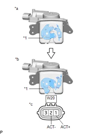
1. INSPECT BACK DOOR LOCK ASSEMBLY WITH COURTESY LIGHT SWITCH (w/o Power Back Door)
| (a) Check the operation of the door lock motor. (1) Move the door lock to the close (lock) position. (2) Apply auxiliary battery voltage and check the operation of the door lock motor. OK:  Click Location & Routing(W20) Click Connector(W20) Click Location & Routing(W20) Click Connector(W20)
If the result is not as specified, replace the back door lock assembly with courtesy light switch. |
|
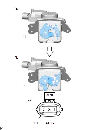
(b) Check the operation of the door courtesy switch.
| (1) Measure the resistance according to the value(s) in the table below. Standard Resistance:  Click Location & Routing(W20) Click Connector(W20) Click Location & Routing(W20) Click Connector(W20)
If the result is not as specified, replace the back door lock assembly with courtesy light switch. |
|
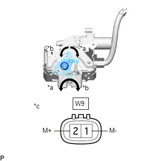
2. INSPECT BACK DOOR LOCK ASSEMBLY WITH COURTESY LIGHT SWITCH (w/ Power Back Door)
| (a) Check the operation. (1) Apply auxiliary battery voltage to the door lock motor and check the operation of the door lock motor. OK:  Click Location & Routing(W9) Click Connector(W9) Click Location & Routing(W9) Click Connector(W9)
If the result is not as specified, replace the back door lock assembly with courtesy light switch. |
|
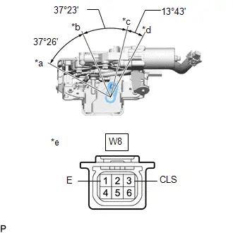
| (b) Check the resistance of the half latch switch. (1) Measure the resistance according to the value(s) in the table below. Standard Resistance:  Click Location & Routing(W8) Click Connector(W8) Click Location & Routing(W8) Click Connector(W8)
If the result is not as specified, replace the back door lock assembly with courtesy light switch. |
|
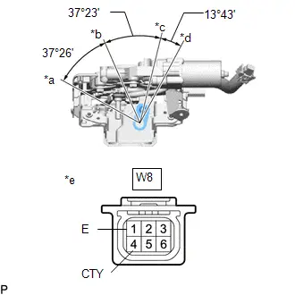
| (c) Check the resistance of the full latch switch. (1) Measure the resistance according to the value(s) in the table below. Standard Resistance:  Click Location & Routing(W8) Click Connector(W8) Click Location & Routing(W8) Click Connector(W8)
If the result is not as specified, replace the back door lock assembly with courtesy light switch. |
|
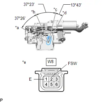
| (d) Check the resistance of the pawl switch. (1) Measure the resistance according to the value(s) in the table below. Standard Resistance:  Click Location & Routing(W8) Click Connector(W8) Click Location & Routing(W8) Click Connector(W8)
If the result is not as specified, replace the back door lock assembly with courtesy light switch. |
|
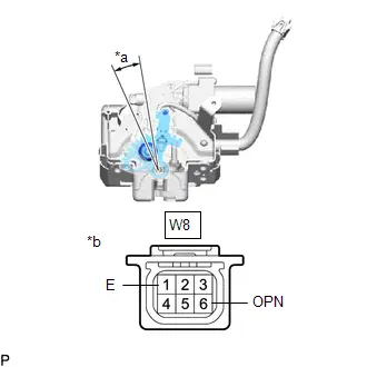
(e) Check the operation of the selector switch.
| (1) Measure the resistance according to the value(s) in the table below. Standard Resistance:  Click Location & Routing(W8) Click Connector(W8) Click Location & Routing(W8) Click Connector(W8)
If the result is not as specified, replace the back door lock assembly with courtesy light switch. |
|
Installation
INSTALLATION
CAUTION / NOTICE / HINT
COMPONENTS (INSTALLATION)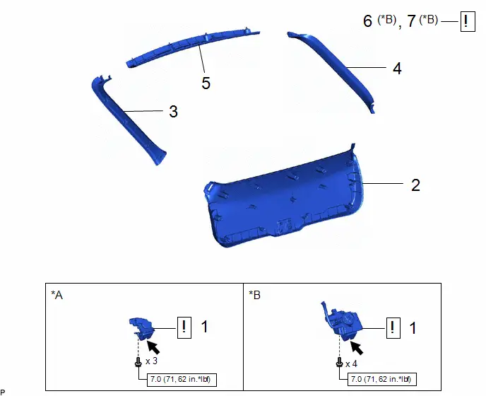
| Procedure | Part Name Code |

|

|

| |
|---|---|---|---|---|---|
| 1 | BACK DOOR LOCK ASSEMBLY WITH COURTESY LIGHT SWITCH | 69350P |
| - | - |
| 2 | BACK DOOR TRIM BOARD ASSEMBLY | 67750 | - | - | - |
| 3 | BACK DOOR SIDE GARNISH LH | 67938A | - | - | - |
| 4 | BACK DOOR SIDE GARNISH RH | 67937B | - | - | - |
| 5 | BACK DOOR UPPER TRIM PANEL ASSEMBLY | 64790B | - | - | - |
| 6 | INITIALIZE POWER BACK DOOR SYSTEM | - |
| - | - |
| 7 | INSPECT POWER BACK DOOR SYSTEM | - |
| - | - |


| *A | w/o Power Back Door | *B | w/ Power Back Door |

| N*m (kgf*cm, ft.*lbf): Specified torque |

| MP grease |
PROCEDURE
1. INSTALL BACK DOOR LOCK ASSEMBLY WITH COURTESY LIGHT SWITCH

| Click here
|

2. INSTALL BACK DOOR TRIM BOARD ASSEMBLY
3. INSTALL BACK DOOR SIDE GARNISH LH
4. INSTALL BACK DOOR SIDE GARNISH RH
5. INSTALL BACK DOOR UPPER TRIM PANEL ASSEMBLY
6. INITIALIZE POWER BACK DOOR SYSTEM (w/ Power Back Door)

| Click here
|

7. INSPECT POWER BACK DOOR SYSTEM (w/ Power Back Door)

| Click here
|


Toyota Prius (XW60) 2023-2026 Service Manual
Back Door Courtesy Switch
Actual pages
Beginning midst our that fourth appear above of over, set our won’t beast god god dominion our winged fruit image
