

Toyota Prius: Air Conditioning Unit
Removal
REMOVAL
CAUTION / NOTICE / HINT
The necessary procedures (adjustment, calibration, initialization or registration) that must be performed after parts are removed and installed, or replaced during air conditioner unit removal/installation are shown below.
Necessary Procedures After Parts Removed/Installed/Replaced| Replaced Part or Performed Procedure | Necessary Procedures | Effect/Inoperative Function When Necessary Procedures are not Performed | Link |
|---|---|---|---|
| *: Even when not replacing the part, it is necessary to perform the specified necessary procedures after installation. | |||
| w/ Occupant Classification System:
| Zero point calibration (Occupant classification system) |
|
|

CAUTION / NOTICE / HINT
CAUTION:
Be sure to read Precaution thoroughly before servicing.
Click here

NOTICE:
After the ignition switch is turned off, there may be a waiting time before disconnecting the negative (-) auxiliary battery terminal.
Click here

HINT:
When the cable is disconnected / reconnected to the auxiliary battery terminal, systems temporarily stop operating. However, each system has a function that completes learning the first time the system is used.
Learning completes when Toyota Prius vehicle is driven| Effect/Inoperative Function When Necessary Procedures are not Performed | Necessary Procedures | Link |
|---|---|---|
| Front Camera System | Drive the Toyota Prius vehicle straight ahead at 35 km/h (22 mph) or more for 5 seconds or more. |
|

| Effect/Inoperative Function When Necessary Procedures are not Performed | Necessary Procedures | Link |
|---|---|---|
|
*1: w/o Power Back Door System
*2: w/ Power Back Door System | ||
| Power Door Lock Control System*1
| Perform door unlock operation with door control switch or electrical key transmitter sub-assembly switch. |
|
| Power Back Door System*2 | Reset back door close position |
|
| Air Conditioning System | for HEV Model:
for PHEV Model:
| - |


CAUTION / NOTICE / HINT
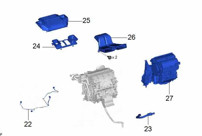
COMPONENTS (REMOVAL)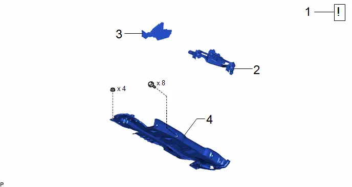
| Procedure | Part Name Code |

|

|

| |
|---|---|---|---|---|---|
| 1 | RECOVER REFRIGERANT FROM REFRIGERATION SYSTEM | - |
| - | - |
| 2 | WINDSHIELD WIPER MOTOR AND LINK ASSEMBLY | - | - | - | - |
| 3 | WATER GUARD PLATE | 55734D | - | - | - |
| 4 | OUTER COWL TOP PANEL SUB-ASSEMBLY | 55701J | - | - | - |

| Procedure | Part Name Code |

|

|

| |
|---|---|---|---|---|---|
| 5 | SUCTION PIPE SUB-ASSEMBLY | 88707 |
| - | - |
| 6 | NO. 1 SUCTION TUBE | 88717U |
| - | - |
| 7 | NO. 7 DISCHARGE TUBE | 88G15H |
| - | - |
| 8 | DISCHARGE TUBE SUB-ASSEMBLY | 88705A |
| - | - |
| 9 | NO. 2 DISCHARGE HOSE SUB-ASSEMBLY | 88703B |
| - | - |
| 10 | WATER HOSE SUB-ASSEMBLY | 87209 |
| - | - |
| 11 | OUTLET HEATER WATER HOSE | 87246 |
| - | - |
| 12 | INLET HEATER WATER HOSE | 87245 |
| - | - |
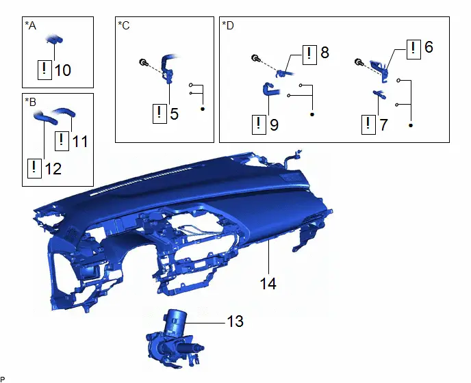
| 13 | STEERING COLUMN ASSEMBLY | - | - | - | - |
| 14 | INSTRUMENT PANEL SAFETY PAD SUB-ASSEMBLY | - | - | - | - |


| *A | for M20A-FXS | *B | for 2ZR-FXE |
| *C | for HEV Model | *D | for PHEV Model |
| ● | Non-reusable part | - | - |

| Procedure | Part Name Code |

|

|

| |
|---|---|---|---|---|---|
| 15 | FRONT SEAT ASSEMBLY LH | - | - | - | - |
| 16 | FRONT SEAT ASSEMBLY RH | - | - | - | - |

| Procedure | Part Name Code |

|

|

| |
|---|---|---|---|---|---|
| 17 | ACCELERATOR PEDAL (WITH SENSOR) ROD ASSEMBLY | 78110K | - | - | - |
| 18 | COOLER (ROOM TEMP. SENSOR) THERMISTOR | 88625Q | - | - | - |
| 19 | FRONT FLOOR CARPET ASSEMBLY | 58510D | - | - | - |
| 20 | REAR NO. 5 AIR DUCT | 87217C | - | - | - |
| 21 | REAR NO. 4 AIR DUCT | 87216B | - | - | - |
| 22 | REAR NO. 2 AIR DUCT | 87213 | - | - | - |
| 23 | REAR NO. 1 AIR DUCT | 87212 | - | - | - |
| 24 | REAR NO. 3 AIR DUCT | 87215F | - | - | - |
| 25 | NO. 3 DASH PANEL INSULATOR PAD | 55215D |
| - | - |

| *A | w/ Rear Air Duct | - | - |
| ● | Non-reusable part | - | - |
| Procedure | Part Name Code |

|

|

| |
|---|---|---|---|---|---|
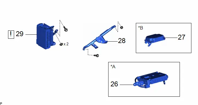
| 26 | DCM (TELEMATICS TRANSCEIVER) WITH BRACKET | - | - | - | - |
| 27 | DRIVER MONITOR ECU ASSEMBLY | 86470 | - | - | - |
| 28 | NO. 3 INSTRUMENT PANEL TO COWL BRACE SUB-ASSEMBLY | 55308B | - | - | - |
| 29 | JUNCTION BLOCK BRACKET WITH POWER DISTRIBUTION BOX ASSEMBLY | - |
| - | - |

| *A | w/ Telematics Transceiver | *B | w/ Driver Monitor Camera |
| Procedure | Part Name Code |

|

|

| |
|---|---|---|---|---|---|
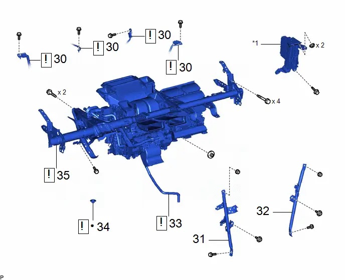
| 30 | INSTRUMENT PANEL WIRE | 82141 |
| - | - |
| 31 | NO. 1 INSTRUMENT PANEL BRACE SUB-ASSEMBLY | 55306A | - | - | - |
| 32 | NO. 2 INSTRUMENT PANEL BRACE SUB-ASSEMBLY | 55307C | - | - | - |
| 33 | DRAIN COOLER HOSE | 88539J |
| - | - |
| 34 | COOLER UNIT DRAIN HOSE GROMMET | 88539G |
| - | - |
| 35 | INSTRUMENT PANEL REINFORCEMENT ASSEMBLY WITH AIR CONDITIONER UNIT ASSEMBLY | - |
| - | - |


| *1 | CONNECTOR HOLDER | - | - |
| ● | Non-reusable part | - | - |

| Procedure | Part Name Code |

|

|

| |
|---|---|---|---|---|---|
| 36 | AIR CONDITIONER UNIT ASSEMBLY | - | - | - | - |
PROCEDURE
1. RECOVER REFRIGERANT FROM REFRIGERATION SYSTEM
(a) for HFC-134a (R134a):
Click here

(b) for HFO-1234yf (R1234yf):
(1) for HEV Model:
Click here

(2) for PHEV Model:
Click here

2. REMOVE WINDSHIELD WIPER MOTOR AND LINK ASSEMBLY
Click here

3. REMOVE WATER GUARD PLATE
Click here

4. REMOVE OUTER COWL TOP PANEL SUB-ASSEMBLY
Click here

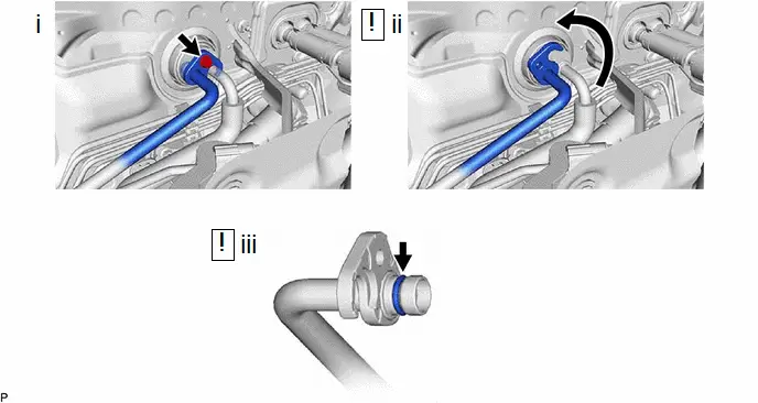
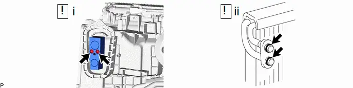
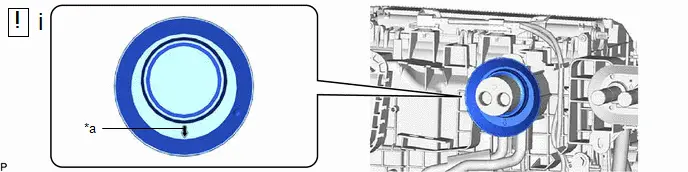
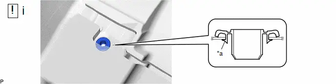
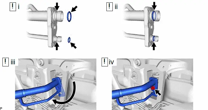
5. DISCONNECT SUCTION PIPE SUB-ASSEMBLY (for HEV Model)
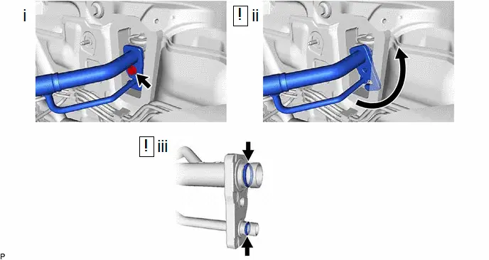
(1) Remove the bolt.
(2) Rotate the hook connector as shown in the illustration and disconnect the suction pipe sub-assembly.
(3) Remove the 2 O-rings from the suction pipe sub-assembly.
NOTICE:
Seal the openings of the disconnected parts using vinyl tape to prevent entry of moisture and foreign matter.
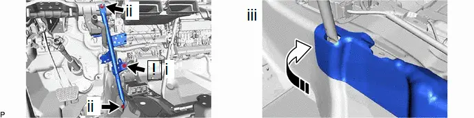
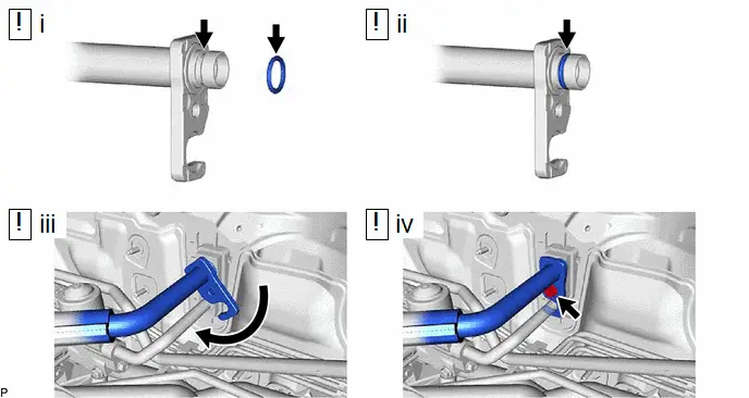
6. DISCONNECT NO. 1 SUCTION TUBE (for PHEV Model)
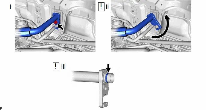
(1) Remove the bolt.
(2) Rotate the hook connector as shown in the illustration and disconnect the No. 1 suction tube.
(3) Remove the O-ring from the No. 1 suction tube.
NOTICE:
Seal the openings of the disconnected parts using vinyl tape to prevent entry of moisture and foreign matter.
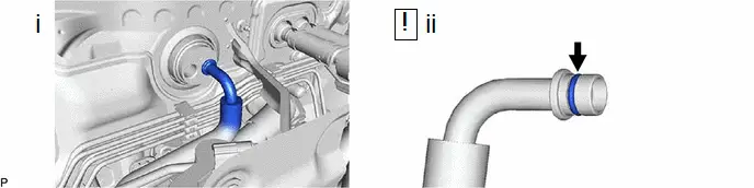
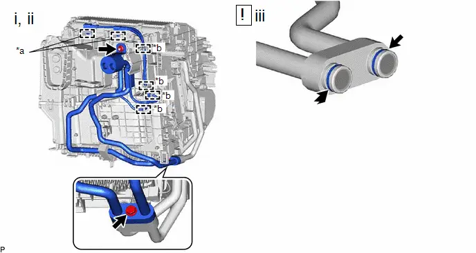
7. DISCONNECT NO. 7 DISCHARGE TUBE (for PHEV Model)
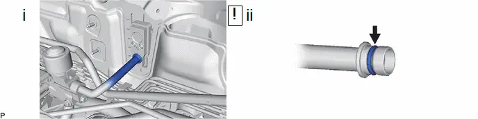
(1) Disconnect the No. 7 discharge tube.
(2) Remove the O-ring from the No. 7 discharge tube.
NOTICE:
Seal the openings of the disconnected parts using vinyl tape to prevent entry of moisture and foreign matter.
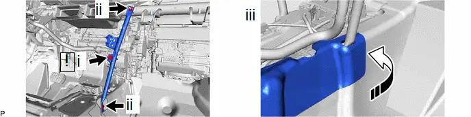
8. DISCONNECT DISCHARGE TUBE SUB-ASSEMBLY (for PHEV Model)
(1) Remove the bolt.
(2) Rotate the hook connector as shown in the illustration and disconnect the discharge tube sub-assembly.
(3) Remove the O-ring from the discharge tube sub-assembly.
NOTICE:
Seal the openings of the disconnected parts using vinyl tape to prevent entry of moisture and foreign matter.
9. DISCONNECT NO. 2 DISCHARGE HOSE SUB-ASSEMBLY (for PHEV Model)
(1) Disconnect the No. 2 discharge hose sub-assembly.
(2) Remove the O-ring from the No. 2 discharge hose sub-assembly.
NOTICE:
Seal the openings of the disconnected parts using vinyl tape to prevent entry of moisture and foreign matter.
10. DISCONNECT WATER HOSE SUB-ASSEMBLY (for M20A-FXS)

(1) Using pliers, grip the claws of the hose clips and slide the hose clips and disconnect the water hose sub-assembly.
NOTICE:
- Do not apply excessive force to the water hose sub-assembly.
- Prepare a drain pan or cloth in case the coolant leaks.
11. DISCONNECT OUTLET HEATER WATER HOSE (for 2ZR-FXE)

(1) Using pliers, grip the claws of the hose clip and slide the hose clip and disconnect the outlet heater water hose.
NOTICE:
- Do not apply excessive force to the outlet heater water hose.
- Prepare a drain pan or cloth in case the coolant leaks.
12. DISCONNECT INLET HEATER WATER HOSE (for 2ZR-FXE)

(1) Using pliers, grip the claws of the hose clip and slide the hose clip and disconnect the inlet heater water hose.
NOTICE:
- Do not apply excessive force to the inlet heater water hose.
- Prepare a drain pan or cloth in case the coolant leaks.
13. REMOVE STEERING COLUMN ASSEMBLY
Click here

14. REMOVE INSTRUMENT PANEL SAFETY PAD SUB-ASSEMBLY
Click here

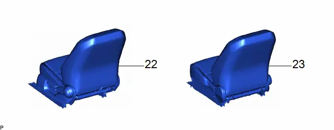
15. REMOVE FRONT SEAT ASSEMBLY LH
(a) for Manual Seat:
Click here

(b) for Power Seat:
Click here

16. REMOVE FRONT SEAT ASSEMBLY RH
(a) Use the same procedure as for the LH side.
17. REMOVE ACCELERATOR PEDAL (WITH SENSOR) ROD ASSEMBLY
Click here

18. REMOVE COOLER (ROOM TEMP. SENSOR) THERMISTOR

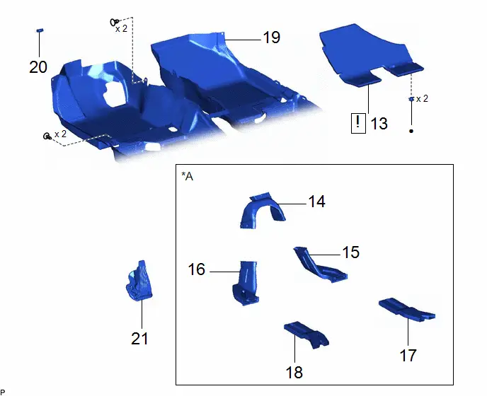
19. DISCONNECT FRONT FLOOR CARPET ASSEMBLY
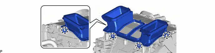
20. REMOVE REAR NO. 5 AIR DUCT (w/ Rear Air Duct)

21. REMOVE REAR NO. 4 AIR DUCT (w/ Rear Air Duct)

22. REMOVE REAR NO. 2 AIR DUCT (w/ Rear Air Duct)

23. REMOVE REAR NO. 1 AIR DUCT (w/ Rear Air Duct)

24. REMOVE REAR NO. 3 AIR DUCT (w/ Rear Air Duct)

25. REMOVE NO. 3 DASH PANEL INSULATOR PAD
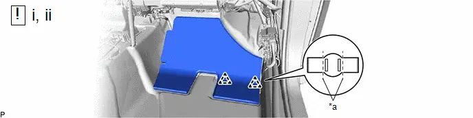
| *a | Cut | - | - |
(1) Cut each claw of the 2 clips and remove the No. 3 dash panel insulator pad.
NOTICE:
If the No. 3 dash panel insulator pad is damaged, replace it with a new one.
(2) Remove the 2 clips.
26. REMOVE DCM (TELEMATICS TRANSCEIVER) WITH BRACKET (w/ Telematics Transceiver)
Click here

27. REMOVE DRIVER MONITOR ECU ASSEMBLY (w/ Driver Monitor Camera)
Click here

28. REMOVE NO. 3 INSTRUMENT PANEL TO COWL BRACE SUB-ASSEMBLY
Click here

29. REMOVE JUNCTION BLOCK BRACKET WITH POWER DISTRIBUTION BOX ASSEMBLY

| Click here
|

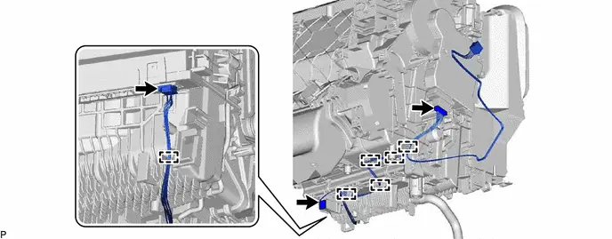
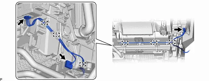
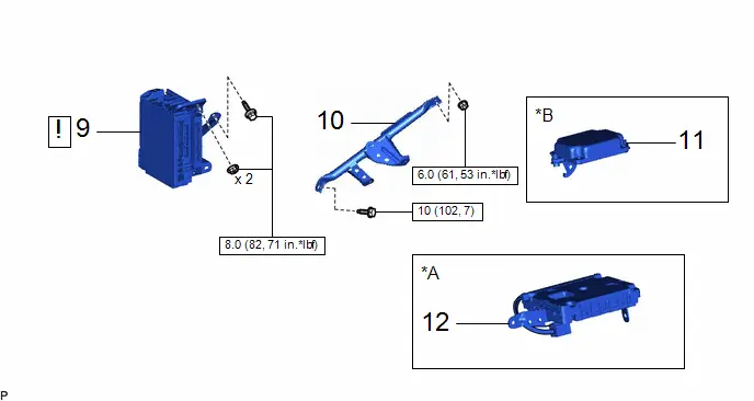
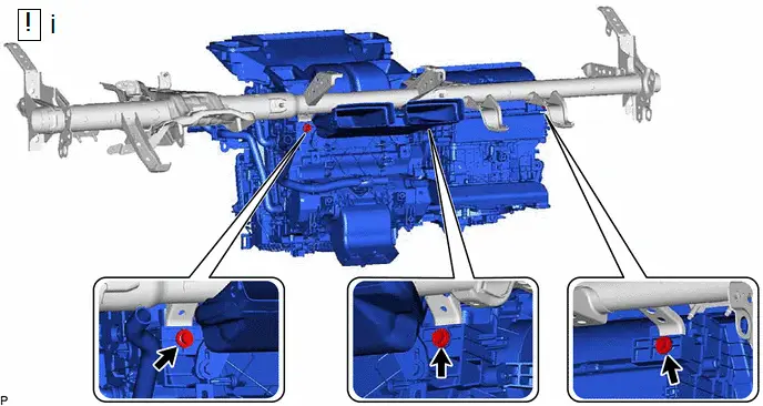
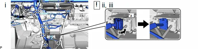
30. DISCONNECT INSTRUMENT PANEL WIRE
HINT:
The illustration shown is an example only. The illustration may differ from the actual parts according to the model.
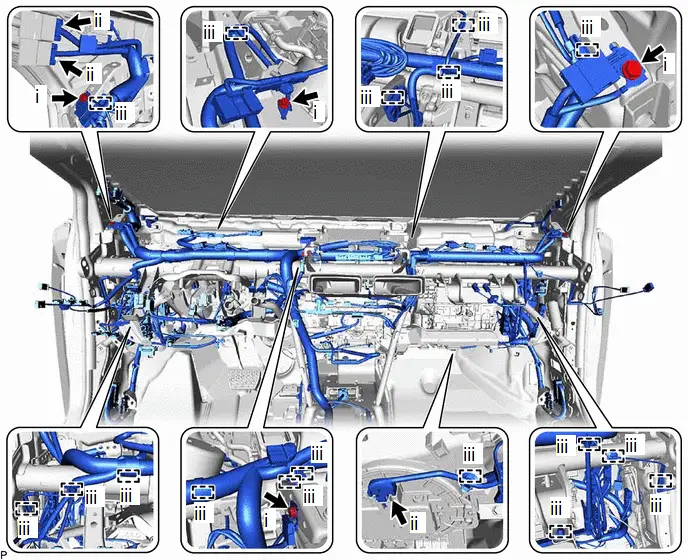
(1) Remove the 4 bolts and disconnect the 4 earth wires.
(2) Disconnect each connector.
(3) Disengage each clamp.

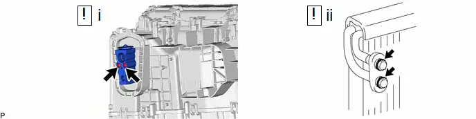
(1) Remove the bolt and 2 nuts, and disconnect the connector holder.
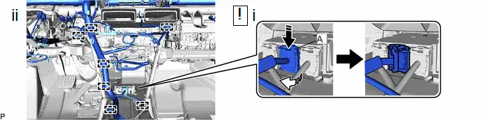

| Release (1) |

| Move in this Direction (2) |
(1) Push down the part (A) in the direction indicated by the arrow (1), to release the lock, and then move the lock lever in the direction indicated by the arrow (2) shown in the illustration to disconnect the connector.
NOTICE:
When disconnecting any airbag connector, take care not to damage the airbag wire harness.
(2) Disengage each clamp and disconnect the instrument panel wire.
31. REMOVE NO. 1 INSTRUMENT PANEL BRACE SUB-ASSEMBLY

| Remove in this Direction | - | - |
32. REMOVE NO. 2 INSTRUMENT PANEL BRACE SUB-ASSEMBLY

| Remove in this Direction | - | - |
33. DISCONNECT DRAIN COOLER HOSE

(1) Disconnect the drain cooler hose from the cooler unit drain hose grommet.
NOTICE:
If the cooler unit drain hose grommet was removed from the Toyota Prius vehicle body, replace it with a new one.
34. REMOVE COOLER UNIT DRAIN HOSE GROMMET
HINT:
Perform this procedure only when replacement of the cooler unit drain hose grommet is necessary.

(1) Remove the cooler unit drain hose grommet.
NOTICE:
After removing the cooler unit drain hose grommet, replace it with a new one to prevent water from entering.
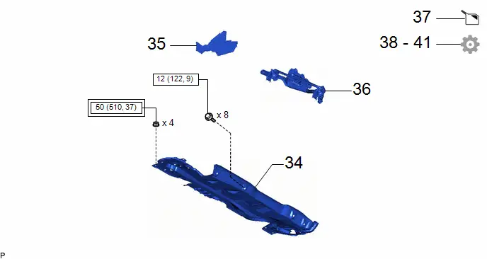
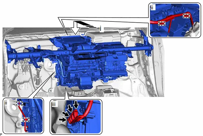
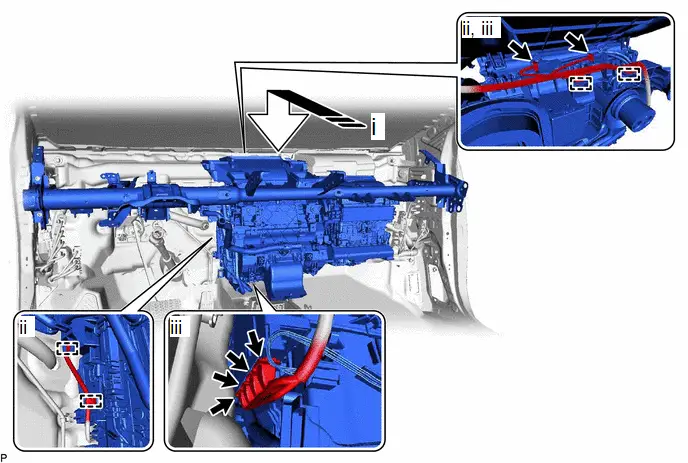
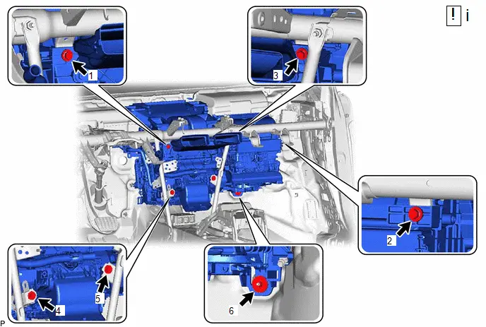
35. REMOVE INSTRUMENT PANEL REINFORCEMENT ASSEMBLY WITH AIR CONDITIONER UNIT ASSEMBLY

| NOTICE:
|

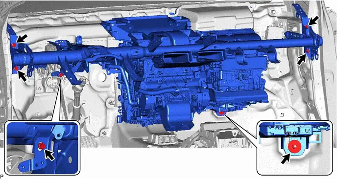
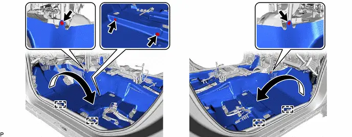
(c) for HEV Model:
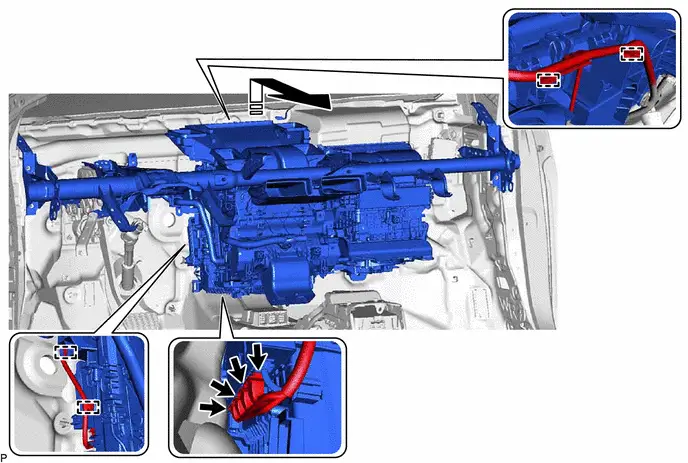

| Remove in this Direction | - | - |
(d) for PHEV Model:
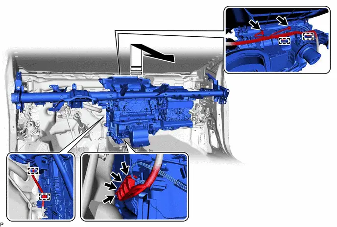

| Remove in this Direction | - | - |
(e) for HEV Model:


| Remove in this Direction | - | - |
(f) for PHEV Model:


| Remove in this Direction | - | - |
36. REMOVE AIR CONDITIONER UNIT ASSEMBLY

Disassembly
DISASSEMBLY
CAUTION / NOTICE / HINT
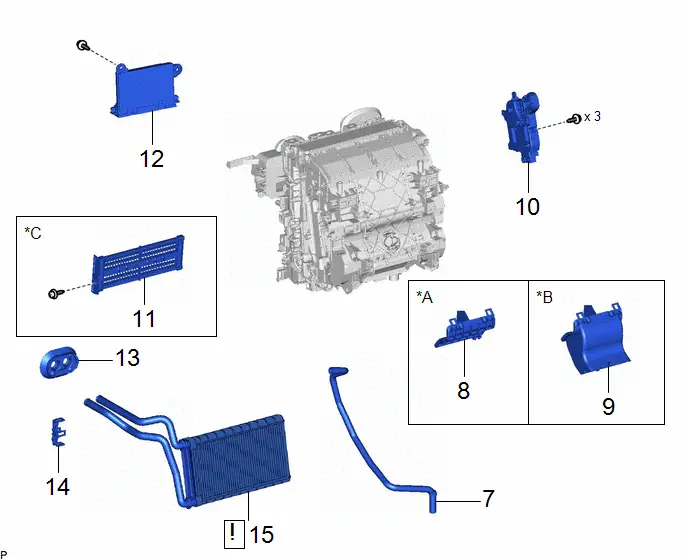
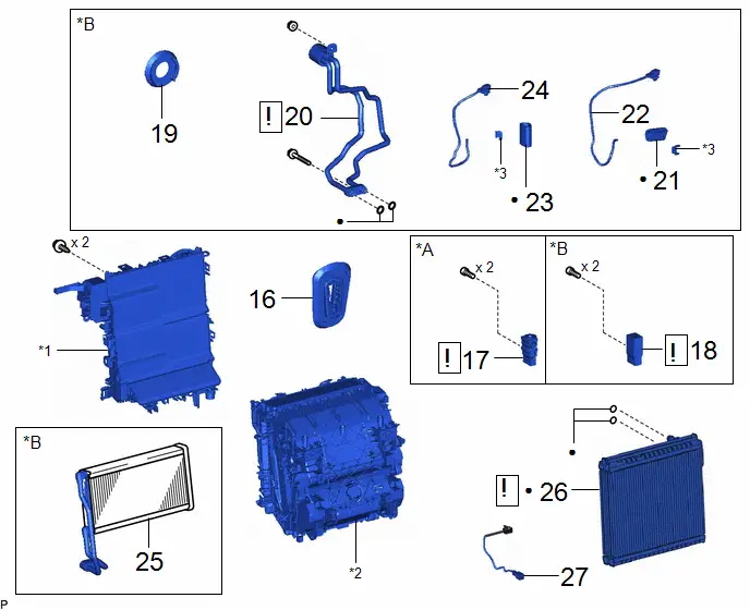
COMPONENTS (DISASSEMBLY)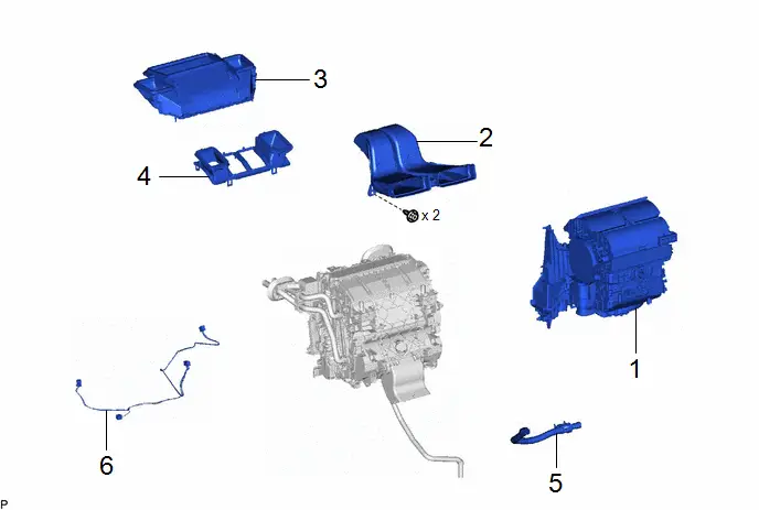
| Procedure | Part Name Code |

|

|

| |
|---|---|---|---|---|---|
| 1 | BLOWER ASSEMBLY | 87130D | - | - | - |
| 2 | NO. 3 HEATER TO REGISTER DUCT SUB-ASSEMBLY | 55086 | - | - | - |
| 3 | LOWER DEFROSTER NOZZLE ASSEMBLY | 55990B | - | - | - |
| 4 | LOWER DEFROSTER NOZZLE | 55967B | - | - | - |
| 5 | ASPIRATOR | 88897P | - | - | - |
| 6 | AIR CONDITIONING HARNESS ASSEMBLY | 82210K | - | - | - |
| Procedure | Part Name Code |

|

|

| |
|---|---|---|---|---|---|
| 7 | DRAIN COOLER HOSE | 88539J | - | - | - |
| 8 | COVER | 88482A | - | - | - |
| 9 | AIR DUCT | 87413 | - | - | - |
| 10 | NO. 1 AIR CONDITIONING RADIATOR DAMPER SERVO SUB-ASSEMBLY | 87050C | - | - | - |
| 11 | HEATER COVER | 87114B | - | - | - |
| 12 | AIR CONDITIONING AMPLIFIER ASSEMBLY | 88650N | - | - | - |
| 13 | HEATER PIPE GROMMET | 88897M | - | - | - |
| 14 | HEATER CLAMP | 87124C | - | - | - |
| 15 | HEATER RADIATOR UNIT SUB-ASSEMBLY | 87107A |
| - | - |

| *A | w/o Rear Air Duct | *B | w/ Rear Air Duct |
| *C | for HEV Model | - | - |
| Procedure | Part Name Code |

|

|

| |
|---|---|---|---|---|---|
| 16 | COOLER PIPE GROMMET | 88899K | - | - | - |
| 17 | COOLER EXPANSION VALVE | 88515 |
| - | - |
| 18 | CONNECTOR TUBE | - |
| - | - |
| 19 | COOLING UNIT PARTS | 88899L | - | - | - |
| 20 | NO. 1 DISCHARGE TUBE | 88715M |
| - | - |
| 21 | NO. 1 COOLING UNIT PACKING | 88578B | - | - | - |
| 22 | INTERNAL CONDENSER TEMPERATURE SENSOR | 88620H | - | - | - |
| 23 | NO. 1 COOLING UNIT PACKING | 88578B | - | - | - |
| 24 | DISCHARGE TEMPERATURE SENSOR | 88620J | - | - | - |
| 25 | CONDENSER ASSEMBLY | 88460Q | - | - | - |
| 26 | NO. 1 COOLER EVAPORATOR SUB-ASSEMBLY | 88501 |
| - | - |
| 27 | NO. 1 COOLER THERMISTOR | 88625 | - | - | - |


| *A | for HEV Model | *B | for PHEV Model |
| *1 | UPPER HEATER CASE | *2 | LOWER HEATER CASE |
| *3 | CLAMP | - | - |
| ● | Non-reusable part | - | - |
PROCEDURE
1. REMOVE BLOWER ASSEMBLY
Click here

2. REMOVE NO. 3 HEATER TO REGISTER DUCT SUB-ASSEMBLY
3. REMOVE LOWER DEFROSTER NOZZLE ASSEMBLY
4. REMOVE LOWER DEFROSTER NOZZLE
5. REMOVE ASPIRATOR

6. REMOVE AIR CONDITIONING HARNESS ASSEMBLY
(a) for HEV Model:
(b) for PHEV Model:
7. REMOVE DRAIN COOLER HOSE

8. REMOVE COVER (w/o Rear Air Duct)

9. REMOVE AIR DUCT (w/ Rear Air Duct)

10. REMOVE NO. 1 AIR CONDITIONING RADIATOR DAMPER SERVO SUB-ASSEMBLY

11. REMOVE HEATER COVER (for HEV Model)


| Remove in this Direction | - | - |
12. REMOVE AIR CONDITIONING AMPLIFIER ASSEMBLY


| Remove in this Direction | - | - |
13. REMOVE HEATER PIPE GROMMET

14. REMOVE HEATER CLAMP

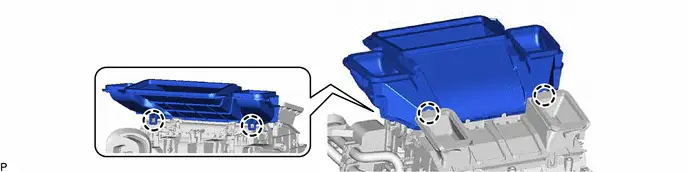
15. REMOVE HEATER RADIATOR UNIT SUB-ASSEMBLY


| Remove in this Direction | - | - |
(1) Remove the heater radiator unit sub-assembly as shown in the illustration.
NOTICE:
Prepare a drain pan or cloth in case the coolant leaks.
16. REMOVE COOLER PIPE GROMMET

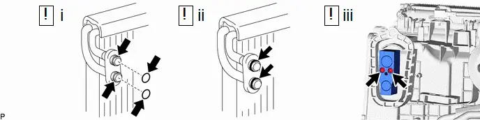
17. REMOVE COOLER EXPANSION VALVE (for HEV Model)
(1) Using a 4 mm hexagon socket wrench, remove the 2 hexagon bolts and cooler expansion valve.
(2) Remove the 2 O-rings from the No. 1 cooler evaporator sub-assembly.
NOTICE:
Seal the openings of the disconnected parts using vinyl tape to prevent moisture and foreign matter from entering them.
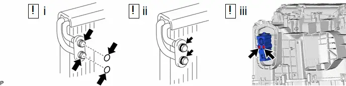
18. REMOVE CONNECTOR TUBE (for PHEV Model)
(1) Using a 4 mm hexagon socket wrench, remove the 2 hexagon bolts and connector tube.
(2) Remove the 2 O-rings from the No. 1 cooler evaporator sub-assembly.
NOTICE:
Seal the openings of the disconnected parts using vinyl tape to prevent moisture and foreign matter from entering them.
19. REMOVE COOLING UNIT PARTS (for PHEV Model)

20. REMOVE NO. 1 DISCHARGE TUBE (for PHEV Model)
| *a | Clamp | *b | Guide |
(1) Disengage the 2 clamps and 4 guides.
(2) Remove the bolt and nut, and No. 1 discharge tube.
(3) Remove the 2 O-rings from the No. 1 discharge tube.
NOTICE:
Seal the openings of the disconnected parts using vinyl tape to prevent moisture and foreign matter from entering them.
21. REMOVE NO. 1 COOLING UNIT PACKING (for PHEV Model)
Click here

22. REMOVE INTERNAL CONDENSER TEMPERATURE SENSOR (for PHEV Model)
Click here

23. REMOVE NO. 1 COOLING UNIT PACKING (for PHEV Model)
Click here

24. REMOVE DISCHARGE TEMPERATURE SENSOR (for PHEV Model)
Click here

25. REMOVE CONDENSER ASSEMBLY (for PHEV Model)


| Remove in this Direction | - | - |
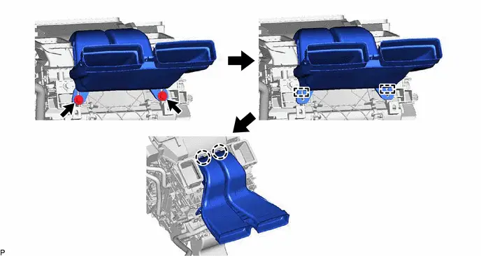
26. REMOVE NO. 1 COOLER EVAPORATOR SUB-ASSEMBLY

| *1 | Upper Heater Case | *2 | Lower Heater Case |
(1) Remove the 2 screws and disengage the 10 claws and 10 guides to remove the upper heater case with No. 1 cooler evaporator sub-assembly from the lower heater case.
(b) for HEV Model:

(1) Disengage the 2 clamps and remove the No. 1 cooler evaporator sub-assembly with No. 1 cooler thermistor from the upper heater case.
NOTICE:
When the No. 1 cooler evaporator sub-assembly is removed, make sure to install a new one. The No. 1 cooler evaporator sub-assembly cannot be reused.
(c) for PHEV Model:

(1) Disengage the 2 clamps and remove the No. 1 cooler evaporator sub-assembly with No. 1 cooler thermistor from the upper heater case.
NOTICE:
When the No. 1 cooler evaporator sub-assembly is removed, make sure to install a new one. The No. 1 cooler evaporator sub-assembly cannot be reused.
27. REMOVE NO. 1 COOLER THERMISTOR
Click here

Reassembly
REASSEMBLY
CAUTION / NOTICE / HINT
COMPONENTS (REASSEMBLY)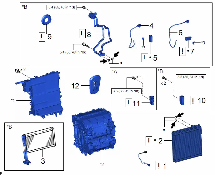
| Procedure | Part Name Code |

|

|

| |
|---|---|---|---|---|---|
| 1 | NO. 1 COOLER THERMISTOR | 88625 |
| - | - |
| 2 | NO. 1 COOLER EVAPORATOR SUB-ASSEMBLY | 88501 |
| - | - |
| 3 | CONDENSER ASSEMBLY | 88460Q | - | - | - |
| 4 | DISCHARGE TEMPERATURE SENSOR | 88620J | - | - | - |
| 5 | NO. 1 COOLING UNIT PACKING | 88578B |
| - | - |
| 6 | INTERNAL CONDENSER TEMPERATURE SENSOR | 88620H | - | - | - |
| 7 | NO. 1 COOLING UNIT PACKING | 88578B |
| - | - |
| 8 | NO. 1 DISCHARGE TUBE | 88715M |
| - | - |
| 9 | COOLING UNIT PARTS | 88899L |
| - | - |
| 10 | CONNECTOR TUBE | - |
| - | - |
| 11 | COOLER EXPANSION VALVE | 88515 |
| - | - |
| 12 | COOLER PIPE GROMMET | 88897K | - | - | - |


| *A | for HEV Model | *B | for PHEV Model |
| *1 | UPPER HEATER CASE | *2 | LOWER HEATER CASE |
| *3 | CLAMP | - | - |

| N*m (kgf*cm, ft.*lbf): Specified torque | ● | Non-reusable part |

| Compressor oil ND-OIL 11 or equivalent | - | - |

| Procedure | Part Name Code |

|

|

| |
|---|---|---|---|---|---|
| 13 | HEATER RADIATOR UNIT SUB-ASSEMBLY | 87107A | - | - | - |
| 14 | HEATER CLAMP | 87124C | - | - | - |
| 15 | HEATER PIPE GROMMET | 88897M |
| - | - |
| 16 | AIR CONDITIONING AMPLIFIER ASSEMBLY | 88650N | - | - | - |
| 17 | HEATER COVER | 87114B | - | - | - |
| 18 | NO. 1 AIR CONDITIONING RADIATOR DAMPER SERVO SUB-ASSEMBLY | 87050C |
| - | - |
| 19 | COVER | 88482A | - | - | - |
| 20 | AIR DUCT | 87413 | - | - | - |
| 21 | DRAIN COOLER HOSE | 88539J |
| - | - |


| *A | w/o Rear Air Duct | *B | w/ Rear Air Duct |
| *C | for HEV Model | - | - |
| Procedure | Part Name Code |

|

|

| |
|---|---|---|---|---|---|
| 22 | AIR CONDITIONING HARNESS ASSEMBLY | 82210K | - | - | - |
| 23 | ASPIRATOR | 88897P | - | - | - |
| 24 | LOWER DEFROSTER NOZZLE | 55967B | - | - | - |
| 25 | LOWER DEFROSTER NOZZLE ASSEMBLY | 55990B | - | - | - |
| 26 | NO. 3 HEATER TO REGISTER DUCT SUB-ASSEMBLY | 55086 | - | - | - |
| 27 | BLOWER ASSEMBLY | 87130D | - | - | - |
PROCEDURE
1. INSTALL NO. 1 COOLER THERMISTOR

| Click here
|

2. INSTALL NO. 1 COOLER EVAPORATOR SUB-ASSEMBLY
(a) for HEV Model:
(1) Engage the 2 clamps and install the No. 1 cooler evaporator sub-assembly with No. 1 cooler thermistor to the upper heater case.
NOTICE:
When the No. 1 cooler evaporator sub-assembly is removed, make sure to install a new one. The No. 1 cooler evaporator sub-assembly cannot be reused.
(b) for PHEV Model:
(1) Engage the 2 clamps and install the No. 1 cooler evaporator sub-assembly with No. 1 cooler thermistor to the upper heater case.
NOTICE:
When the No. 1 cooler evaporator sub-assembly is removed, make sure to install a new one. The No. 1 cooler evaporator sub-assembly cannot be reused.
| *1 | Upper Heater Case | *2 | Lower Heater Case |
(1) Engage the 10 claws, 10 guides and install the upper heater case with No. 1 cooler evaporator sub-assembly to the lower heater case with the 2 screws.
3. INSTALL CONDENSER ASSEMBLY (for PHEV Model)
4. INSTALL DISCHARGE TEMPERATURE SENSOR (for PHEV Model)
Click here

5. INSTALL NO. 1 COOLING UNIT PACKING (for PHEV Model)

| Click here
|

6. INSTALL INTERNAL CONDENSER TEMPERATURE SENSOR (for PHEV Model)
Click here

7. INSTALL NO. 1 COOLING UNIT PACKING (for PHEV Model)

| Click here
|

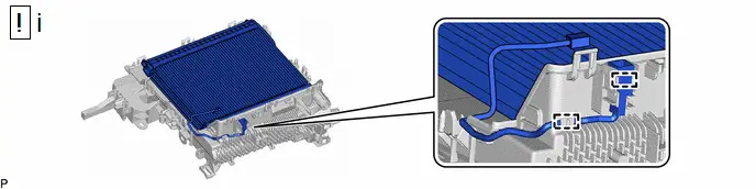
8. INSTALL NO. 1 DISCHARGE TUBE (for PHEV Model)
| *a | Clamp | *b | Guide |
(1) Remove the vinyl tape from the No. 1 discharge tube, and sufficiently apply compressor oil to 2 new O-rings and the fitting surfaces of the No. 1 discharge tube.
Compressor Oil:
ND-OIL 11 or equivalent
(2) Install the 2 O-rings to the No. 1 discharge tube.
NOTICE:
Keep the O-rings and O-ring fitting surfaces free of foreign matter.
(3) Install the No. 1 discharge tube with the bolt and nut.
Torque:
5.4 N·m {55 kgf·cm, 48 in·lbf}
(4) Engage the 4 guides and 2 clamps.
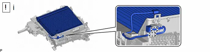
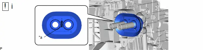
9. INSTALL COOLING UNIT PARTS (for PHEV Model)
| *a | Reference Point | - | - |
(1) Install the cooling unit parts as shown in the illustration.
NOTICE:
Install the cooling unit parts with the arrow facing down.
10. INSTALL CONNECTOR TUBE (for PHEV Model)
(1) Remove the vinyl tape from the No. 1 cooler evaporator sub-assembly, and sufficiently apply compressor oil to 2 new O-rings and the fitting surfaces of the No. 1 cooler evaporator sub-assembly.
Compressor Oil:
ND-OIL 11 or equivalent
(2) Install the 2 O-rings to the No. 1 cooler evaporator sub-assembly.
NOTICE:
Keep the O-rings and O-ring fitting surfaces free of foreign matter.
(3) Using a 4 mm hexagon socket wrench, install the connector tube with the 2 hexagon bolts.
Torque:
3.5 N·m {36 kgf·cm, 31 in·lbf}
11. INSTALL COOLER EXPANSION VALVE (for HEV Model)
(1) Remove the vinyl tape from the No. 1 cooler evaporator sub-assembly, and sufficiently apply compressor oil to 2 new O-rings and the fitting surfaces of the No. 1 cooler evaporator sub-assembly.
Compressor Oil:
ND-OIL 11 or equivalent
(2) Install the 2 O-rings to the No. 1 cooler evaporator sub-assembly.
NOTICE:
Keep the O-rings and O-ring fitting surfaces free of foreign matter.
(3) Using a 4 mm hexagon socket wrench, install the cooler expansion valve with the 2 hexagon bolts.
Torque:
3.5 N·m {36 kgf·cm, 31 in·lbf}
12. INSTALL COOLER PIPE GROMMET
13. INSTALL HEATER RADIATOR UNIT SUB-ASSEMBLY
14. INSTALL HEATER CLAMP
15. INSTALL HEATER PIPE GROMMET
| *a | Reference Point | - | - |
(1) Install the heater pipe grommet as shown in the illustration.
NOTICE:
Install the heater pipe grommet with the arrow facing up.
16. INSTALL AIR CONDITIONING AMPLIFIER ASSEMBLY
17. INSTALL HEATER COVER (for HEV Model)
18. INSTALL NO. 1 AIR CONDITIONING RADIATOR DAMPER SERVO SUB-ASSEMBLY
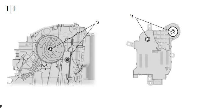
| *a | Reference Point | - | - |
(1) Align each gear on the air conditioning radiator assembly as shown in the illustration, and then check that the gears of the No. 1 air conditioning radiator damper servo sub-assembly are aligned as shown in the illustration.

(1) Engage the 2 guides to install the No. 1 air conditioning radiator damper servo sub-assembly with the 3 screws.
19. INSTALL COVER (w/o Rear Air Duct)
20. INSTALL AIR DUCT (w/ Rear Air Duct)
21. INSTALL DRAIN COOLER HOSE
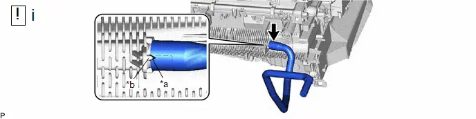
| *a | Hose Notch | *b | Rib |
(1) Align the hose notch with the rib as shown in the illustration and install the drain cooler hose.
22. INSTALL AIR CONDITIONING HARNESS ASSEMBLY
23. INSTALL ASPIRATOR
24. INSTALL LOWER DEFROSTER NOZZLE
25. INSTALL LOWER DEFROSTER NOZZLE ASSEMBLY
26. INSTALL NO. 3 HEATER TO REGISTER DUCT SUB-ASSEMBLY
27. INSTALL BLOWER ASSEMBLY
Click here

Installation
INSTALLATION
CAUTION / NOTICE / HINT
COMPONENTS (INSTALLATION)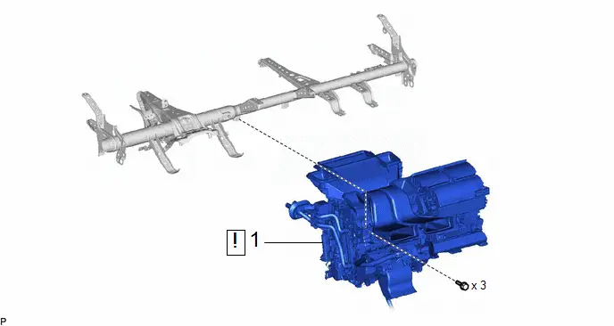
| Procedure | Part Name Code |

|

|

| |
|---|---|---|---|---|---|
| 1 | TEMPORARILY INSTALL AIR CONDITIONER UNIT ASSEMBLY | - |
| - | - |

| Procedure | Part Name Code |

|

|

| |
|---|---|---|---|---|---|
| 2 | INSTRUMENT PANEL REINFORCEMENT ASSEMBLY WITH AIR CONDITIONER UNIT ASSEMBLY | - |
| - | - |
| 3 | COOLER UNIT DRAIN HOSE GROMMET | 88539G |
| - | - |
| 4 | DRAIN COOLER HOSE | 88539J | - | - | - |
| 5 | NO. 2 INSTRUMENT PANEL BRACE SUB-ASSEMBLY | 55307C |
| - | - |
| 6 | NO. 1 INSTRUMENT PANEL BRACE SUB-ASSEMBLY | 55306A |
| - | - |
| 7 | INSTALL AIR CONDITIONER UNIT ASSEMBLY | - |
| - | - |
| 8 | INSTRUMENT PANEL WIRE | 82141 |
| - | - |


| *1 | CONNECTOR HOLDER | - | - |

| Tightening torque for "Major areas involving basic Toyota Prius vehicle performance such as moving/turning/stopping": N*m (kgf*cm, ft.*lbf) |

| N*m (kgf*cm, ft.*lbf): Specified torque |
| ● | Non-reusable part | - | - |
| Procedure | Part Name Code |

|

|

| |
|---|---|---|---|---|---|
| 9 | JUNCTION BLOCK BRACKET WITH POWER DISTRIBUTION BOX ASSEMBLY | - |
| - | - |
| 10 | NO. 3 INSTRUMENT PANEL TO COWL BRACE SUB-ASSEMBLY | 55308B | - | - | - |
| 11 | DRIVER MONITOR ECU ASSEMBLY | 86470 | - | - | - |
| 12 | DCM (TELEMATICS TRANSCEIVER) WITH BRACKET | - | - | - | - |

| *A | w/ Telematics Transceiver | *B | w/ Driver Monitor Camera |

| N*m (kgf*cm, ft.*lbf): Specified torque | - | - |
| Procedure | Part Name Code |

|

|

| |
|---|---|---|---|---|---|
| 13 | NO. 3 DASH PANEL INSULATOR PAD | 55215D |
| - | - |
| 14 | REAR NO. 3 AIR DUCT | 87215F | - | - | - |
| 15 | REAR NO. 1 AIR DUCT | 87212 | - | - | - |
| 16 | REAR NO. 2 AIR DUCT | 87213 | - | - | - |
| 17 | REAR NO. 4 AIR DUCT | 87216B | - | - | - |
| 18 | REAR NO. 5 AIR DUCT | 87217C | - | - | - |
| 19 | FRONT FLOOR CARPET ASSEMBLY | 58510D | - | - | - |
| 20 | COOLER (ROOM TEMP. SENSOR) THERMISTOR | 88625Q | - | - | - |
| 21 | ACCELERATOR PEDAL (WITH SENSOR) ROD ASSEMBLY | 78110K | - | - | - |

| *A | w/ Rear Air Duct | - | - |
| ● | Non-reusable part | - | - |
| Procedure | Part Name Code |

|

|

| |
|---|---|---|---|---|---|
| 22 | FRONT SEAT ASSEMBLY LH | - | - | - | - |
| 23 | FRONT SEAT ASSEMBLY RH | - | - | - | - |

| Procedure | Part Name Code |

|

|

| |
|---|---|---|---|---|---|
| 24 | INSTRUMENT PANEL SAFETY PAD SUB-ASSEMBLY | - | - | - | - |
| 25 | STEERING COLUMN ASSEMBLY | - | - | - | - |
| 26 | WATER HOSE SUB-ASSEMBLY | 87209 |
| - | - |
| 27 | INLET HEATER WATER HOSE | 87245 |
| - | - |
| 28 | OUTLET HEATER WATER HOSE | 87246 |
| - | - |
| 29 | NO. 2 DISCHARGE HOSE SUB-ASSEMBLY | 88703B |
| - | - |
| 30 | DISCHARGE TUBE SUB-ASSEMBLY | 88705A |
| - | - |
| 31 | NO. 7 DISCHARGE TUBE | 88G15H |
| - | - |
| 32 | NO. 1 SUCTION TUBE | 88717U |
| - | - |
| 33 | SUCTION PIPE SUB-ASSEMBLY | 88707 |
| - | - |


| *A | for M20A-FXS | *B | for 2ZR-FXE |
| *C | for HEV Model | *D | for PHEV Model |

| N*m (kgf*cm, ft.*lbf): Specified torque | ● | Non-reusable part |

| Compressor oil ND-OIL 11 or equivalent | - | - |
| Procedure | Part Name Code |

|

|

| |
|---|---|---|---|---|---|
| 34 | OUTER COWL TOP PANEL SUB-ASSEMBLY | 55701J | - | - | - |
| 35 | WATER GUARD PLATE | 55734D | - | - | - |
| 36 | WINDSHIELD WIPER MOTOR AND LINK ASSEMBLY | - | - | - | - |
| 37 | ADD ENGINE COOLANT (for Engine) | - | - |
| - |
| 38 | INSPECT FOR COOLANT LEAK (for Engine) | - | - | - |
|
| 39 | CHARGE AIR CONDITIONING SYSTEM WITH REFRIGERANT | - | - | - |
|
| 40 | WARM UP COMPRESSOR | - | - | - |
|
| 41 | INSPECT FOR REFRIGERANT LEAK | - | - | - |
|


| Tightening torque for "Major areas involving basic Toyota Prius vehicle performance such as moving/turning/stopping": N*m (kgf*cm, ft.*lbf) |

| N*m (kgf*cm, ft.*lbf): Specified torque |
PROCEDURE
1. TEMPORARILY INSTALL AIR CONDITIONER UNIT ASSEMBLY
(1) Temporarily install the air conditioner unit assembly to the instrument panel reinforcement assembly with the 3 bolts.
2. INSTALL INSTRUMENT PANEL REINFORCEMENT ASSEMBLY WITH AIR CONDITIONER UNIT ASSEMBLY

| NOTICE:
|
(a) for HEV Model:


| Install in this Direction | - | - |
(b) for PHEV Model:


| Install in this Direction | - | - |
(c) for HEV Model:

| Install in this Direction | - | - |
(1) Temporarily install the instrument panel reinforcement assembly with air conditioner unit assembly as shown in the illustration.
(2) Engage each clamp.
(3) Connect each connector.
(d) for PHEV Model:

| Install in this Direction | - | - |
(1) Temporarily install the instrument panel reinforcement assembly with air conditioner unit assembly as shown in the illustration.
(2) Engage each clamp.
(3) Connect each connector.
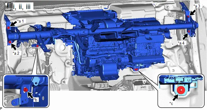
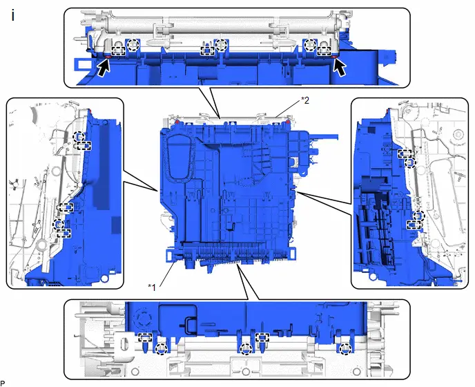
| *a | Bolt (A) | *b | Bolt (B) |
| *c | Nut | - | - |
(1) Install the instrument panel reinforcement assembly with air conditioner unit assembly with the 4 bolts (A).
Torque:
25 N·m {255 kgf·cm, 18 ft·lbf}
NOTICE:
Tighten the bolts in the order shown in the illustration.
(2) Install the bolt (B).
Torque:
15 N·m {153 kgf·cm, 11 ft·lbf}
(3) Temporarily install the nut.
HINT:
Do not fully tighten the nut.

(1) Install the 2 bolts.
Torque:
25 N·m {255 kgf·cm, 18 ft·lbf}
3. INSTALL COOLER UNIT DRAIN HOSE GROMMET
| *a | Lip | - | - |
(1) Install a new cooler unit drain hose grommet.
NOTICE:
- If the drain cooler hose is disconnected from the cooler unit drain hose grommet, make sure to replace the cooler unit drain hose grommet with a new one. Failure to do so may lead to water ingress.
- Make sure that the entire lip of the cooler unit drain hose grommet is securely engaged to the Toyota Prius vehicle body.
4. CONNECT DRAIN COOLER HOSE
5. INSTALL NO. 2 INSTRUMENT PANEL BRACE SUB-ASSEMBLY

| Install in this Direction | - | - |
(1) Temporarily install the screw.
HINT:
Do not fully tighten the screw.
(2) Install the No. 2 instrument panel brace sub-assembly with the bolt and nut.
Torque:
Bolt :
20 N·m {204 kgf·cm, 15 ft·lbf}
Nut :
18 N·m {184 kgf·cm, 13 ft·lbf}
(3) Install the front floor mat to the original position as shown in the illustration.
6. INSTALL NO. 1 INSTRUMENT PANEL BRACE SUB-ASSEMBLY

| Install in this Direction | - | - |
(1) Temporarily install the screw.
HINT:
Do not fully tighten the screw.
(2) Install the No. 1 instrument panel brace sub-assembly with the bolt and nut.
Torque:
Bolt :
20 N·m {204 kgf·cm, 15 ft·lbf}
Nut :
18 N·m {184 kgf·cm, 13 ft·lbf}
(3) Install the front floor mat to the original position as shown in the illustration.
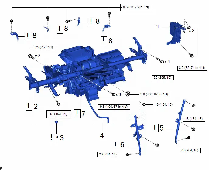
7. INSTALL AIR CONDITIONER UNIT ASSEMBLY
(1) Tighten the 3 bolts, nut and 2 screws to install the air conditioner unit assembly.
Torque:
Bolt :
9.8 N·m {100 kgf·cm, 87 in·lbf}
Nut :
9.8 N·m {100 kgf·cm, 87 in·lbf}
NOTICE:
Tighten the bolts, nut and screws in the order shown in the illustration.
8. CONNECT INSTRUMENT PANEL WIRE
HINT:
The illustration shown is an example only. The illustration may differ from the actual parts according to the model.
| *a | Lock Lever | - | - |

| Move in this Direction | - | - |
(1) Engage each clamp.
(2) Temporarily connect the connector and then move the lock lever as shown in the illustration to securely connect the connector.
NOTICE:
When connecting any airbag connector, take care not to damage the airbag wire harness.
(3) Check that there is no looseness in the installed parts of the airbag sensor assembly.

(1) Connect the connector holder with the bolt and 2 nuts.
Torque:
8.0 N·m {82 kgf·cm, 71 in·lbf}

(1) Engage each clamp to connect the instrument panel wire.
(2) Connect each connector.
(3) Connect the 4 earth wires with the 4 bolts.
Torque:
8.5 N·m {87 kgf·cm, 75 in·lbf}
9. INSTALL JUNCTION BLOCK BRACKET WITH POWER DISTRIBUTION BOX ASSEMBLY

| Click here
|

10. INSTALL NO. 3 INSTRUMENT PANEL TO COWL BRACE SUB-ASSEMBLY
Click here

11. INSTALL DRIVER MONITOR ECU ASSEMBLY (w/ Driver Monitor Camera)
Click here

12. INSTALL DCM (TELEMATICS TRANSCEIVER) WITH BRACKET (w/ Telematics Transceiver)
Click here

13. INSTALL NO. 3 DASH PANEL INSULATOR PAD
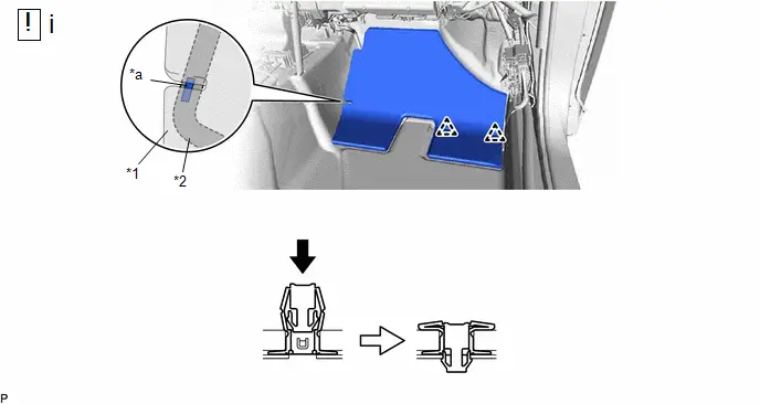
| *1 | No. 3 Dash Panel Insulator Pad | *2 | Drain Cooler Hose |
| *a | Paint Mark | - | - |
(1) Install the No. 3 dash panel insulator pad with 2 new clips as shown in the illustration.
NOTICE:
After installing the No. 3 dash panel insulator pad, check that the paint mark of the drain cooler hose can be seen from the position shown in the illustration.
14. INSTALL REAR NO. 3 AIR DUCT (w/ Rear Air Duct)
15. INSTALL REAR NO. 1 AIR DUCT (w/ Rear Air Duct)
16. INSTALL REAR NO. 2 AIR DUCT (w/ Rear Air Duct)
17. INSTALL REAR NO. 4 AIR DUCT (w/ Rear Air Duct)
18. INSTALL REAR NO. 5 AIR DUCT (w/ Rear Air Duct)
19. INSTALL FRONT FLOOR CARPET ASSEMBLY
20. INSTALL COOLER (ROOM TEMP. SENSOR) THERMISTOR
21. INSTALL ACCELERATOR PEDAL (WITH SENSOR) ROD ASSEMBLY
Click here

22. INSTALL FRONT SEAT ASSEMBLY LH
(a) for Manual Seat:
Click here

(b) for Power Seat:
Click here

23. INSTALL FRONT SEAT ASSEMBLY RH
(a) Use the same procedure as for the LH side.
24. INSTALL INSTRUMENT PANEL SAFETY PAD SUB-ASSEMBLY
Click here

25. INSTALL STEERING COLUMN ASSEMBLY
Click here

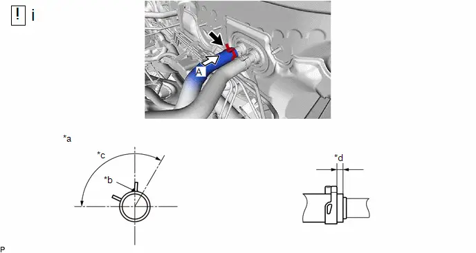
26. CONNECT WATER HOSE SUB-ASSEMBLY (for M20A-FXS)
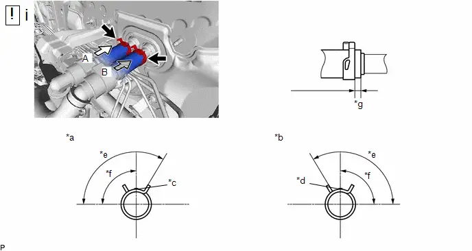
| *a | View A | *b | View B |
| *c | Marking (Purple) | *d | Marking (Yellow) |
| *e | Hose Clip Installation Range (120°) | *f | 90° |
| *g | Hose Clip Installation Range (2.0 to 6.0 mm (0.0787 to 0.236 in.)) | - | - |
(1) Connect the water hose sub-assembly with the marking facing up and engage the hose clips within the area shown in the illustration.
NOTICE:
Do not apply excessive force to the water hose sub-assembly.
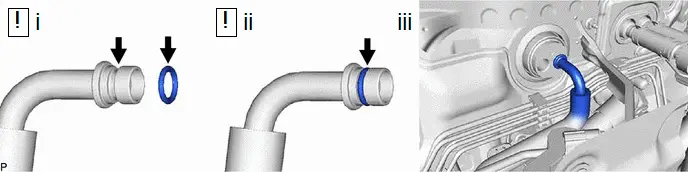
27. CONNECT INLET HEATER WATER HOSE (for 2ZR-FXE)
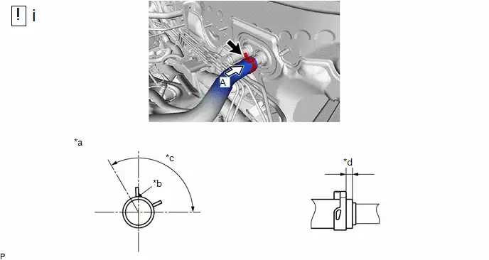
| *a | View A | *b | Marking (Blue) |
| *c | Hose Clip Installation Range (120°) | *d | Hose Clip Installation Range (2.0 to 7.0 mm (0.0787 to 0.276 in.)) |
(1) Connect the inlet heater water hose with the marking facing up and engage the clip within the area shown in the illustration.
NOTICE:
Do not apply excessive force to the inlet heater water hose.
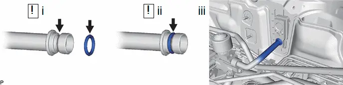
28. CONNECT OUTLET HEATER WATER HOSE (for 2ZR-FXE)
| *a | View A | *b | Marking (Pink) |
| *c | Hose Clip Installation Range (120°) | *d | Hose Clip Installation Range (2.0 to 7.0 mm (0.0787 to 0.276 in.)) |
(1) Connect the outlet heater water hose with the marking facing up and engage the clip within the area shown in the illustration.
NOTICE:
Do not apply excessive force to the outlet heater water hose.
29. CONNECT NO. 2 DISCHARGE HOSE SUB-ASSEMBLY (for PHEV Model)
(1) Remove the vinyl tape from the No. 2 discharge hose sub-assembly, sufficiently apply compressor oil to a new O-ring and the fitting surface of the No. 2 discharge hose sub-assembly.
Compressor Oil:
ND-OIL 11 or equivalent
(2) Install the O-ring to the No. 2 discharge hose sub-assembly.
NOTICE:
Keep the O-ring and O-ring fitting surface free of foreign matter.
(3) Connect the No. 2 discharge hose sub-assembly.
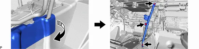
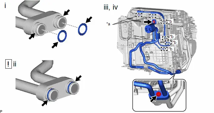
30. CONNECT DISCHARGE TUBE SUB-ASSEMBLY (for PHEV Model)
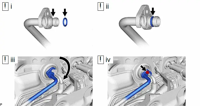
(1) Remove the vinyl tape from the discharge tube sub-assembly, sufficiently apply compressor oil to a new O-ring and the fitting surface of the discharge tube sub-assembly.
Compressor Oil:
ND-OIL 11 or equivalent
(2) Install the O-ring to the discharge tube sub-assembly.
NOTICE:
Keep the O-ring and O-ring fitting surface free of foreign matter.
(3) Connect the discharge tube sub-assembly and rotate the hook connector as shown in the illustration.
(4) Insert the tube joint into the fitting hole securely and install the bolt.
Torque:
5.4 N·m {55 kgf·cm, 48 in·lbf}
31. CONNECT NO. 7 DISCHARGE TUBE (for PHEV Model)
(1) Remove the vinyl tape from the No. 7 discharge tube, sufficiently apply compressor oil to a new O-ring and the fitting surface of the No. 7 discharge tube.
Compressor Oil:
ND-OIL 11 or equivalent
(2) Install the O-ring to the No. 7 discharge tube.
NOTICE:
Keep the O-ring and O-ring fitting surface free of foreign matter.
(3) Connect the No. 7 discharge tube.
32. CONNECT NO. 1 SUCTION TUBE (for PHEV Model)
(1) Remove the vinyl tape from the No. 1 suction tube, sufficiently apply compressor oil to a new O-ring and the fitting surface of the No. 1 suction tube.
Compressor Oil:
ND-OIL 11 or equivalent
(2) Install the O-ring to the No. 1 suction tube.
NOTICE:
Keep the O-ring and O-ring fitting surface free of foreign matter.
(3) Connect the No. 1 suction tube and rotate the hook connector as shown in the illustration.
(4) Insert the tube joint into the fitting hole securely and install the bolt.
Torque:
5.4 N·m {55 kgf·cm, 48 in·lbf}
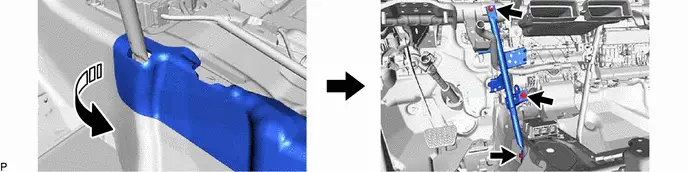
33. CONNECT SUCTION PIPE SUB-ASSEMBLY (for HEV Model)
(1) Remove the vinyl tape from the suction pipe sub-assembly, sufficiently apply compressor oil to 2 new O-rings and the fitting surface of the suction pipe sub-assembly.
Compressor Oil:
ND-OIL 11 or equivalent
(2) Install the 2 O-rings to the suction pipe sub-assembly.
NOTICE:
Keep the O-ring and O-ring fitting surface free of foreign matter.
(3) Connect the suction pipe sub-assembly and rotate the hook connector as shown in the illustration.
(4) Insert the tube joint into the fitting hole securely and install the bolt.
Torque:
9.8 N·m {100 kgf·cm, 87 in·lbf}
34. INSTALL OUTER COWL TOP PANEL SUB-ASSEMBLY
Click here

35. INSTALL WATER GUARD PLATE
36. INSTALL WINDSHIELD WIPER MOTOR AND LINK ASSEMBLY
Click here

37. ADD ENGINE COOLANT (for Engine)
(a) for M20A-FXS:
Click here

(b) for 2ZR-FXE:
Click here

38. INSPECT FOR COOLANT LEAK (for Engine)
(a) for M20A-FXS:
Click here

(b) for 2ZR-FXE:
Click here

39. CHARGE AIR CONDITIONING SYSTEM WITH REFRIGERANT
(a) for HFC-134a (R134a):
Click here

(b) for HFO-1234yf (R1234yf):
Click here

40. WARM UP COMPRESSOR
(a) for HFC-134a (R134a):
Click here

(b) for HFO-1234yf (R1234yf):
Click here

41. INSPECT FOR REFRIGERANT LEAK
(a) for HFC-134a (R134a):
Click here

(b) for HFO-1234yf (R1234yf):
Click here


Toyota Prius (XW60) 2023-2026 Service Manual
Air Conditioning Unit
Actual pages
Beginning midst our that fourth appear above of over, set our won’t beast god god dominion our winged fruit image
