

Toyota Prius: Air Conditioning Pressure Sensor
On-vehicle Inspection
ON-VEHICLE INSPECTION
PROCEDURE
1. INSPECT AIR CONDITIONING PRESSURE SENSOR (for PHEV Model)
Pre-procedure1
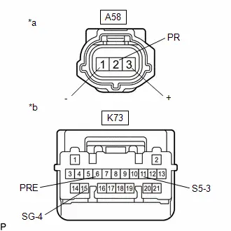
(a) Disconnect the A58 air conditioning pressure sensor connector.
(b) Disconnect the K73 air conditioning amplifier assembly connector.
Procedure1
| (c) Measure the resistance according to the value(s) in the table below. Standard Resistance:  Click Location & Routing(A58,K73) Click Connector(A58) Click Connector(K73) Click Location & Routing(A58,K73) Click Connector(A58) Click Connector(K73)
If the resistance is not as specified, repair or replace the wire harness. |
|
Post-procedure1
(d) Connect the K73 air conditioning amplifier assembly connector.
Pre-procedure2
(e) Turn the ignition switch to ON.
Procedure2
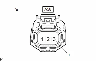
| (f) Measure the voltage according to the value(s) in the table below. Standard Voltage:  Click Location & Routing(A58) Click Connector(A58) Click Location & Routing(A58) Click Connector(A58)
If the result is not as specified, repair or replace the wire harness or replace the air conditioning amplifier assembly. |
|

Post-procedure2
(g) Connect the A58 air conditioning pressure sensor connector.
Pre-procedure3
(h) Install a manifold gauge set.
(i) Turn the A/C switch on.
Procedure3
(j) Measure the voltage according to the value(s) in the table below.
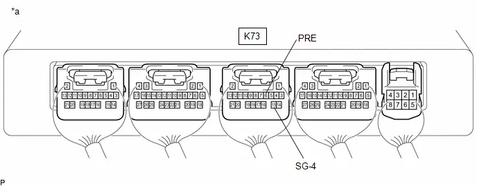
| *a | Component with harness connected (Air Conditioning Amplifier Assembly) | - | - |
HINT:
Check from the rear of the connector while it is connected to the air conditioning amplifier assembly.
Standard Voltage:
 Click Location & Routing(K73) Click Connector(K73)
 | Tester Connection | Condition | Specified Condition | Result |
|---|---|---|---|
| While sensor voltage is 5 V. | |||
| K73-6 (PRE) - K73-15 (SG-4) | Refrigerant pressure: Normal pressure (less than 2812 kPa (28.6 kgf/cm2, 408 psi) and more than 196 kPa (2.0 kgf/cm2, 28 psi))*3 | 0.62 to 4.73 V | V |
If the voltage is not as specified, replace the air conditioning pressure sensor.
Post-procedure3
(k) None
2. INSPECT AIR CONDITIONING PRESSURE SENSOR (for HEV Model)
Pre-procedure1
(a) Disconnect the A58 air conditioning pressure sensor connector.
(b) Disconnect the K73 air conditioning amplifier assembly connector.
Procedure1
| (c) Measure the resistance according to the value(s) in the table below. Standard Resistance:  Click Location & Routing(A58,K73) Click Connector(A58) Click Connector(K73) Click Location & Routing(A58,K73) Click Connector(A58) Click Connector(K73)
If the resistance is not as specified, repair or replace the wire harness. |
|

Post-procedure1
(d) Connect the K73 air conditioning amplifier assembly connector.
Pre-procedure2
(e) Turn the ignition switch to ON.
Procedure2
| (f) Measure the voltage according to the value(s) in the table below. Standard Voltage:  Click Location & Routing(A58) Click Connector(A58) Click Location & Routing(A58) Click Connector(A58)
If the result is not as specified, repair or replace the wire harness or replace the air conditioning amplifier assembly. |
|
Post-procedure2
(g) Connect the A58 air conditioning pressure sensor connector.
Pre-procedure3
(h) Install a manifold gauge set.
(i) Turn the A/C switch on.
Procedure3
(j) Measure the voltage according to the value(s) in the table below.
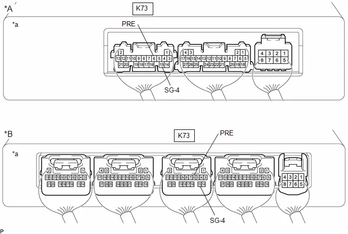
| *A | w/o Seat Heater System | *B | w/ Seat Heater System |
| *a | Component with harness connected (Air Conditioning Amplifier Assembly) | - | - |
HINT:
Check from the rear of the connector while it is connected to the air conditioning amplifier assembly.
Standard Voltage:
 Click Location & Routing(K73) Click Connector(K73)
 | Tester Connection | Condition | Specified Condition | Result |
|---|---|---|---|
|
While sensor voltage is 5 V.
*1: for HFC-134a (R134a) *2: for HFO-1234yf (R1234yf) | |||
| K73-6 (PRE) - K73-15 (SG-4) | Refrigerant pressure: Normal pressure (less than 3025 kPa (30.8 kgf/cm2, 439 psi) and more than 176 kPa (1.8 kgf/cm2, 26 psi))*1 | 0.62 to 4.73 V | V |
| K73-6 (PRE) - K73-15 (SG-4) | Refrigerant pressure: Normal pressure (less than 2812 kPa (28.6 kgf/cm2, 408 psi) and more than 196 kPa (2.0 kgf/cm2, 28 psi))*2 | 0.62 to 4.73 V | V |
If the voltage is not as specified, replace the air conditioning pressure sensor.
Post-procedure3
(k) None
Removal
REMOVAL
CAUTION / NOTICE / HINT
The necessary procedures (adjustment, calibration, initialization or registration) that must be performed after parts are removed and installed, or replaced during air conditioning pressure sensor removal/installation are shown below.
Necessary Procedures After Parts Removed/Installed/Replaced| Replaced Part or Performed Procedure | Necessary Procedures | Effect/Inoperative Function When Necessary Procedures are not Performed | Link |
|---|---|---|---|
| *: Even when not replacing the part, it is necessary to perform the specified necessary procedures after installation. | |||
| Front bumper assembly* | Front television camera view adjustment | Panoramic View Monitor System |
|
| Advanced Park |
| ||


CAUTION / NOTICE / HINT
COMPONENTS (REMOVAL)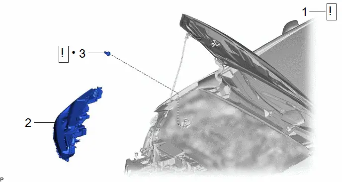
| Procedure | Part Name Code |

|

|

| |
|---|---|---|---|---|---|
| 1 | RECOVER REFRIGERANT FROM REFRIGERATION SYSTEM | - |
| - | - |
| 2 | HEADLIGHT ASSEMBLY RH | - | - | - | - |
| 3 | AIR CONDITIONING PRESSURE SENSOR | 88719A |
| - | - |


| ● | Non-reusable part | - | - |
PROCEDURE
1. RECOVER REFRIGERANT FROM REFRIGERATION SYSTEM
(a) for HFC-134a (R134a):
Click here

(b) for HFO-1234yf (R1234yf):
Click here

2. REMOVE HEADLIGHT ASSEMBLY RH
Click here

3. REMOVE AIR CONDITIONING PRESSURE SENSOR
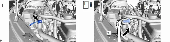
| *a | Turn | *b | Hold |
(1) Disconnect the connector.
(2) Using a 27 mm deep socket wrench, remove the air conditioning pressure sensor as shown in the illustration.
NOTICE:
Seal the openings of the disconnected parts using vinyl tape to prevent entry of moisture and foreign matter.

Toyota Prius (XW60) 2023-2026 Service Manual
Air Conditioning Pressure Sensor
Actual pages
Beginning midst our that fourth appear above of over, set our won’t beast god god dominion our winged fruit image
