

Toyota Prius: Wireless Charging System
- Precaution
- Parts Location
- System Diagram
- System Description
- How To Proceed With Troubleshooting
- Operation Check
- Problem Symptoms Table
- Terminals Of Ecu
- Wireless Charger Power Source Circuit
- Status Signal Circuit
Precaution
PRECAUTION
PRECAUTION FOR WHEN USING WIRELESS CHARGER
(a) As the wireless charger is a device for charging smartphones, do not charge anything other than a smartphone.
(b) When charging a smartphone while driving, for safety reasons, the driver should not operate the smartphone.
(c) People with implantable cardiac pacemakers, cardiac resynchronization therapy pacemakers or implantable cardioverter defibrillators, or any other electrical medical device, should consult their physician about usage of the wireless charging system. Operation of the wireless charging system may have an affect on medical devices.
(d) If the following precautions are not observed, a fire, equipment failure or damage, or burns due to overheating may occur:
- Do not put any metallic objects between the charging area and the smartphone while charging.
- Do not attach metallic objects, such as aluminum stickers, to the charging area, the smartphone or its case.
- Do not cover the smartphone with a cloth or other object while charging.
- Do not attempt to charge any device that is not a specified smartphone.
- Do not disassemble, modify or remove the mobile wireless charger cradle assembly.
- Do not subject the mobile wireless charger cradle assembly to excessive force or impact.
(e) In the following situations, the wireless charging system may not operate correctly:
- When the smartphone is fully charged.
- When a small object or cushion material with a thickness of 2 mm (0.079 in.) or more is in between the charging area and the smartphone.
- When a non-Qi-compatible cover or accessory is attached to the smartphone.
- When a case with a thickness of 2 mm (0.079 in.) or more or non-Qi-compatible cover or accessory is attached to the smartphone.
- When there is a decoration in the charging area or smartphone.
- When a metal plate or magnetic case is used in the charging area.
- When a case with a cushion material, etc. that increases its thickness is used in the charging area.
- When a smartphone that has a case with a ring installed is used.
- When the temperature around the charging tray is 35 °C (95 °F) or more due to insolation, etc.
- When a smartphone is not placed correctly on the charging area.
- When a smartphone is not centered on the charging area.
- When in an area with strong radio waves, noise, etc.
- When the smartphone is in contact with, or is covered by a metallic object.
- When an RF remote controller is being used nearby.
(f) Do not bring magnetic cards, such as electronic toll collection cards or contactless IC cards, or magnetic recording media close to the charging area while charging. Otherwise, data may be erased. Additionally, do not bring precision instruments, such as wrist watches, close to the mobile wireless charger cradle assembly, as such objects may malfunction.
(g) To prevent the auxiliary battery from discharging, do not use the wireless charging system for a long period of time with the ignition switch in a state other than ON (READY).
Parts Location
PARTS LOCATION
ILLUSTRATION
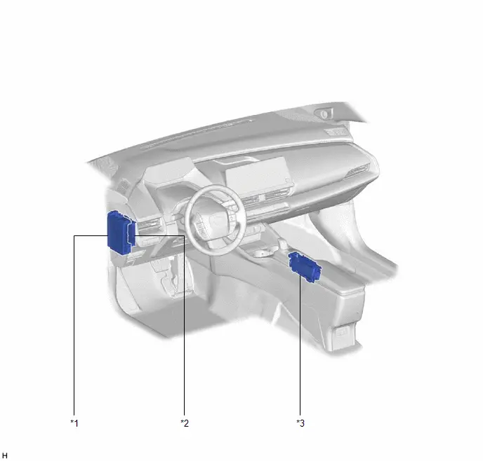
| *1 | POWER DISTRIBUTION BOX ASSEMBLY - ECU-ACC FUSE - ECU-B NO. 3 FUSE | *2 | CERTIFICATION ECU (SMART KEY ECU ASSEMBLY) |
| *3 | MOBILE WIRELESS CHARGER CRADLE ASSEMBLY | - | - |
System Diagram
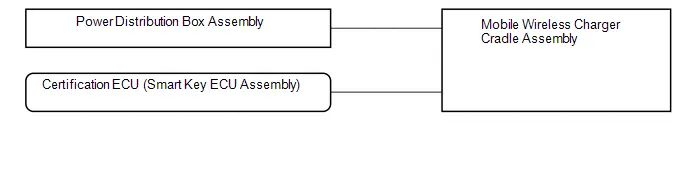
SYSTEM DIAGRAM
System Description
SYSTEM DESCRIPTION
WIRELESS CHARGER FUNCTION OUTLINE
(a) The wireless charging system enables Qi-compatible* smartphones to be recharged by merely placing it on the charging area of the mobile wireless charger cradle assembly.
HINT:
*: Qi (pronounced chee) is a wireless technology which allows devices to recharge without using any wires.
(b) Smartphones which do not fit within the charging area cannot be used. If a Qi-compatible smartphone does not operate normally, refer to the owner's manual of the device.
(c) Qi-compatible smartphones can be charged.
HINT:
- "Qi" and "Qi" logo are trademarks of the Wireless Power Consortium (WPC).
- Although the wireless charging system meets Qi standards, compatibility with all Qi-compatible devices is not guaranteed.
OPERATION INDICATOR LIGHT STATUS
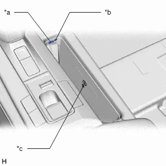
| *a | Power Supply Switch |
| *b | Operation Indicator Light (Green/Amber) |
| *c | Charging Area |
(a) The operation indicator light shows the operation condition of the wireless charging system.
| Operation Indicator | Operation Condition | |
|---|---|---|
| Condition | Color | |
|
*1: Some smartphone, cases or accessories may not cause the indicator (green) to illuminate when charging is complete, even though they are Qi-compatible. Check the smartphone to confirm the charge status.
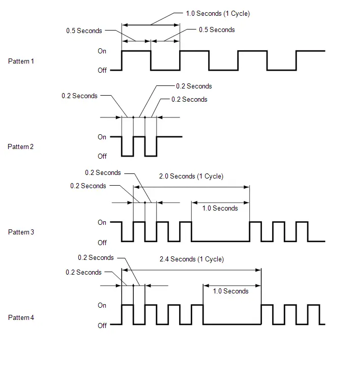
*2: Refer to the following diagram for details about the indicator blinking patterns. | ||
| Off | - | Wireless charging system is turned off |
| On | Green |
|
| On | Amber |
|
| Blinks (Pattern 1)*2 | Amber | An open in the charging suspension signal circuit is detected |
| Blinks (Pattern 2)*2 | Amber | The charging frequency is being changed |
| Blinks (Pattern 3)*2 | Amber |
|
| Blinks (Pattern 4)*2 | Amber |
|
RESUMPTION OF CHARGING
(a) After charging is complete, if the smartphone is left in the same position on the charging area, charging will resume after 30 minutes elapse.
(b) Charging will resume if the smartphone is moved or repositioned within the charging area, or replaced with another smartphone within 30 minutes of charging being completed.
(c) If the smartphone is moved while it is being charged, charging will resume when the smartphone is placed on the charging area.
SUSPENSION OF CHARGING DUE TO VERIFICATION OF ELECTRICAL KEY TRANSMITTER SUB-ASSEMBLY
(a) The wireless charging system uses the same radio wave frequency that is used to perform verification of the electrical key transmitter sub-assembly. Therefore, when the electrical key transmitter sub-assembly verification is being performed, the certification ECU (smart key ECU assembly) sends a charging suspension signal to the wireless charging system to suspend charging.
HINT:
- When charging is suspended due to the charging suspension signal, the indicator (green) will illuminate.
- If there is an open in the charging suspension signal circuit, the indicator (amber) will blink (pattern 2).
(b) The certification ECU (smart key ECU assembly) sends the charging suspension signal when any of the following conditions is met:
- Opening/closing the doors
- Pressing the back door opener switch assembly
- Closing the back door
- Starting the hybrid system
- Moving the electrical key transmitter sub-assembly out of the detection area
CHARGING FREQUENCY SWITCHING FUNCTION
(a) If noise is generated in the AM radio during charging, turn the wireless charging system off and check if the noise is reduced. If the noise is reduced, press and hold the mobile wireless charging switch for approximately 2 seconds to change the charging frequency and reduce the noise.
HINT:
When the charging frequency is being changed, the operation indicator light (amber) blinks (pattern 2).
How To Proceed With Troubleshooting
CAUTION / NOTICE / HINT
HINT:
Use the following procedure to troubleshoot the wireless charging system.
PROCEDURE
| 1. | VEHICLE BROUGHT TO WORKSHOP |
|

| 2. | CUSTOMER PROBLEM ANALYSIS |
HINT:
- In troubleshooting, confirm that the problem symptoms have been accurately identified. Preconceptions should be discarded in order to make an accurate judgment. To clearly understand what the problem symptoms are, it is extremely important to ask the customer about the problem and the conditions at the time the malfunction occurred.
- Gather as much information as possible for reference. Past problems that seem unrelated may also help in some cases.
-
The following 5 items are important points for problem analysis:
What
Toyota Prius Vehicle model, system name
When
Date, time, occurrence frequency
Where
Road conditions
Under what conditions?
Driving conditions, weather conditions
How did it happen?
Problem symptoms
|

| 3. | PRE-CHECK |
(a) Measure the auxiliary battery voltage with the ignition switch off.
Standard Voltage:
11 to 14 V
If the voltage is below 11 V, recharge or replace the auxiliary battery before proceeding to the next step.
(b) Check the fuses and relays.
(c) Check the connector connections and terminals to make sure that there are no abnormalities such as loose connections, deformation, etc.
|

| 4. | PROBLEM SYMPTOMS TABLE |
(a) Refer to Problem Symptoms Table.
Click here

| Result | Proceed to |
|---|---|
| Fault is not listed in Problem Symptoms Table | A |
| Fault is listed in Problem Symptoms Table | B |
| B |

| GO TO STEP 6 |
|

| 5. | OVERALL ANALYSIS AND TROUBLESHOOTING |
(a) Operation Check.
Click here

(b) Terminals of ECU.
Click here

|

| 6. | REPAIR OR REPLACE |
|

| 7. | CONFIRMATION TEST |
| NEXT |

| END |
Operation Check
OPERATION CHECK
WIRELESS CHARGING SYSTEM OPERATION CHECK
(a) Turn the ignition switch to ON or ACC and check that the operation indicator light (green) illuminates.

| *a | Power Supply Switch |
| *b | Operation Indicator Light (Green/Amber) |
| *c | Charging Area |
(b) Place a smartphone on the charging area and check that the operation indicator light (amber) illuminates, indicating charging is in progress.
HINT:
Refer to Precaution for details about Qi-compatible rechargeable devices.
Click here

(c) Check that the operation indicator light (green) illuminates when charging is complete.
HINT:
Some smartphones, cases or accessories may not cause the operation indicator light (green) to illuminate when charging is complete, even though they are Qi-compatible. Check the smartphone to confirm the charge status.
(d) Turn the ignition switch off and check that the operation indicator light turns off.
Problem Symptoms Table
PROBLEM SYMPTOMS TABLE
HINT:
- Use the table below to help determine the cause of problem symptoms. If multiple suspected areas are listed, the potential causes of the symptoms are listed in order of probability in the "Suspected Area" column of the table. Check each symptom by checking the suspected areas in the order they are listed. Replace parts as necessary.
- Inspect the fuses and relays related to this system before inspecting the suspected areas below.
| Symptom | Suspected Area | Link |
|---|---|---|
| Even when the wireless charging system is turned on, the indicator light (green) does not illuminate | Wireless charger power source circuit |
|
| Mobile wireless charger cradle assembly |
| |
| When the wireless charging system is turned on, the indicator (green) illuminates, but the indicator (amber) does not illuminate when a rechargeable device is placed on the charging area (wireless charging does not start) | Operate the ignition switch and confirm that the power source mode is ON or ACC | - |
| Check that the device being used is a Qi-compatible rechargeable device | - | |
| Remove any cases and accessories | - | |
| Check that there is no gap of 2 mm (0.079 in.) or more between the charging area and smartphone | - | |
| Check that there are no foreign objects with a thickness of 2 mm (0.079 in.) or more between the charging area and smartphone | - | |
| Check that the rechargeable device is not fully charged | - | |
| Check that the rechargeable device is centered on the charging area | - | |
| Check that the smartphone is placed on the charging area with its charging surface facing correct orientation | - | |
| Check that the Toyota Prius vehicle is not in an environment where it may be affected by strong radio waves or electrical noise | - | |
| Check if more than 1 smartphone is placed on the charging area | - | |
| Check that a charging cable is not connected to the smartphone | - | |
| Check that temperature of the smartphone is not excessively high or low | - | |
| Check if wireless charging of the smartphone is possible using another Qi-compatible wireless charging system | - | |
| Check if wireless charging is possible using another Qi-compatible smartphone | - | |
| Status signal circuit |
| |
| Mobile wireless charger cradle assembly |
| |
| When the wireless charging system is turned on, the indicator (green) illuminates and when a smartphone is placed on the charging area, the indicator (amber) illuminates, but the indicator (green) illuminates again before wireless charging is completed (wireless charging does not complete) | Check if the smartphone has not been moved out of the charging area | - |
| Check that temperature of the smartphone is not excessively high or low | - | |
| Check that the Toyota Prius vehicle is not in an environment where it may be affected by strong radio waves or electrical noise | - | |
| When the ignition switch is ACC, check that the situation of the vehicle searching for the electrical key (brake pedal is continually depressed, door is open, electrical key transmitter sub-assembly carried out of the Toyota Prius vehicle, etc.) is not occurring | - | |
| Status signal circuit |
| |
| Mobile wireless charger cradle assembly |
| |
| The indicator light (amber) blinks (pattern 1)* | Status signal circuit |
|
| Mobile wireless charger cradle assembly |
| |
| The indicator light (amber) blinks (pattern 2)* | Check if the charging frequency is being changed |
|
| Mobile wireless charger cradle assembly |
| |
| The indicator light (amber) blinks (pattern 3)* | Check that the device being used is a Qi-compatible smartphone | - |
| Remove any cases and accessories | - | |
| Check that there is no gap of 2 mm (0.079 in.) or more between the charging area and smartphone | - | |
| Check that there are no foreign objects with a thickness of 2 mm (0.079 in.) or more between the charging area and smartphone | - | |
| Check that the smartphone is centered on the charging area | - | |
| Check that the smartphone is in the same position as when charging was started | - | |
| Mobile wireless charger cradle assembly |
| |
| The indicator light (amber) blinks (pattern 4)* | Check that temperature of the mobile wireless charger cradle assembly is not excessively high | - |
| Mobile wireless charger cradle assembly |
|


-
*: For details about the indicator blinking patterns, refer to System Description.
Click here

Terminals Of Ecu
TERMINALS OF ECU
CHECK MOBILE WIRELESS CHARGER CRADLE ASSEMBLY (FRONT CONSOLE BOX INSERT SUB-ASSEMBLY)

| Terminal No. (Symbol) | Terminal Description | Condition | Specified Condition |
|---|---|---|---|
| K46-1 (PGND) - Body ground | Ground | Always | Below 1 V |
| K46-3 (ACC) - K46-1 (PGND) | Power source (ACC) | Ignition switch ACC | 11 to 14 V |
| Ignition switch off | Below 1 V | ||
| K46-4 (B ) - K46-1 (PGND) | Power source ( B) | Ignition switch off | 11 to 14 V |
| K46-8 (DIS) - Body ground | Charging suspension signal | For 5 seconds after turning ignition switch from off to ACC*1 | 4.5 to 6.0 V |
| Device being charged | Below 1 V | ||
| Charging suspended due to smart entry and start system status*2 | 4.5 to 6.0 V |
- *1: When the ignition switch is turned from off to ACC, the mobile wireless charger cradle assembly monitors the charging suspension signal for 5 seconds. If the charging suspension signal is not 4 V or more for 0.8 seconds or more during monitoring, the mobile wireless charger cradle assembly determines that there is an open in the charging suspension signal line, blinks (pattern 1) the indicator light (amber), and prohibits operation until the ignition switch is turned from off to ACC again.
-
*2: For details about conditions when the certification ECU (smart key ECU assembly) sends the charging suspension signal, refer to System Description.
Click here

Wireless Charger Power Source Circuit
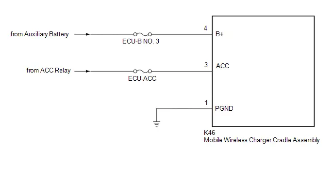
DESCRIPTION
This is the power source circuit for the mobile wireless charger cradle assembly.
WIRING DIAGRAM
CAUTION / NOTICE / HINT
NOTICE:
Inspect the fuses for circuits related to this system before performing the following procedure.
PROCEDURE
| 1. | CHECK HARNESS AND CONNECTOR (MOBILE WIRELESS CHARGER CRADLE ASSEMBLY POWER SOURCE) |
(a) Disconnect the K46 mobile wireless charger cradle assembly connector.
(b) Measure the resistance according to the value(s) in the table below.
Standard Resistance:
 Click Location & Routing(K46) Click Connector(K46)
 | Tester Connection | Condition | Specified Condition |
|---|---|---|
| K46-1 (PGND) - Body ground | Always | Below 1 Ω |
(c) Measure the voltage according to the value(s) in the table below.
Standard Voltage:
 Click Location & Routing(K46) Click Connector(K46)
 | Tester Connection | Condition | Specified Condition |
|---|---|---|
| K46-4 (B ) - Body ground | Ignition switch off | 11 to 14 V |
| K46-3 (ACC) - Body ground | Ignition switch ACC | 11 to 14 V |
| OK |

| PROCEED TO NEXT SUSPECTED AREA SHOWN IN PROBLEM SYMPTOMS TABLE |
| NG |

| REPAIR OR REPLACE HARNESS OR CONNECTOR |
Status Signal Circuit
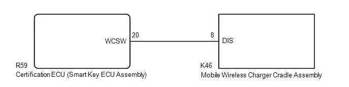
DESCRIPTION
This circuit sends a charging suspension signal from the certification ECU (smart key ECU assembly) to the mobile wireless charger cradle assembly. Based on this signal, the mobile wireless charger cradle assembly suspends or resumes wireless charging.
HINT:
The wireless charging system uses the same radio wave frequency that is used to perform verification of the electrical key transmitter sub-assembly. Therefore, when the electrical key transmitter sub-assembly verification is being performed, the certification ECU (smart key ECU assembly) sends a charging suspension signal to the wireless charging system to suspend charging.
WIRING DIAGRAM
CAUTION / NOTICE / HINT
NOTICE:
Before replacing the certification ECU (smart key ECU assembly), refer to Registration.
Click here

PROCEDURE
| 1. | CHECK MOBILE WIRELESS CHARGER CRADLE ASSEMBLY (DIS TERMINAL) |
(a) Measure the voltage according to the value(s) in the table below.
Standard Voltage:
 Click Location & Routing(K46) Click Connector(K46)
 | Tester Connection | Condition | Specified Condition |
|---|---|---|
| K46-8 (DIS) - Body ground | For 5 seconds after turning ignition switch from off to ACC*1 | 4.5 to 6.0 V |
| Device being charged | Below 1 V | |
| Charging suspended due to smart key system status*2 | 4.5 to 6.0 V |
- *1: When the ignition switch is turned from off to ACC, the mobile wireless charger cradle assembly monitors the charging suspension signal for 5 seconds. If the charging suspension signal is not 4 V or more for 0.8 seconds or more during monitoring, the mobile wireless charger cradle assembly determines that there is an open in the charging suspension signal line, blinks (pattern 1) the indicator light (amber), and prohibits operation until the ignition switch is turned from off to ACC again.
-
*2: For details about conditions when the certification ECU (smart key ECU assembly) sends the charging suspension signal, refer to System Description.
Click here

| OK |

| PROCEED TO NEXT SUSPECTED AREA SHOWN IN PROBLEM SYMPTOMS TABLE |
|

| 2. | CHECK HARNESS AND CONNECTOR (CERTIFICATION ECU (SMART KEY ECU ASSEMBLY) - MOBILE WIRELESS CHARGER CRADLE ASSEMBLY |
(a) Disconnect the R59 certification ECU (smart key ECU assembly) connector.
(b) Disconnect the K46 mobile wireless charger cradle assembly connector.
(c) Measure the resistance according to the value(s) in the table below.
Standard Resistance:
 Click Location & Routing(R59,K46) Click Connector(R59) Click Connector(K46)
 | Tester Connection | Condition | Specified Condition |
|---|---|---|
| R59-20 (WCSW) - K46-8 (DIS) | Always | Below 1 Ω |
| R59-20 (WCSW) or K46-8 (DIS) - Body ground | Always | 10 kΩ or higher |
| OK |

| REPLACE CERTIFICATION ECU (SMART KEY ECU ASSEMBLY)
|


| NG |

| REPAIR OR REPLACE HARNESS OR CONNECTOR |

Toyota Prius (XW60) 2023-2026 Service Manual
Wireless Charging System
- Precaution
- Parts Location
- System Diagram
- System Description
- How To Proceed With Troubleshooting
- Operation Check
- Problem Symptoms Table
- Terminals Of Ecu
- Wireless Charger Power Source Circuit
- Status Signal Circuit
Actual pages
Beginning midst our that fourth appear above of over, set our won’t beast god god dominion our winged fruit image
