

Toyota Prius: Wiper And Washer System
- Precaution
- Parts Location
- System Diagram
- How To Proceed With Troubleshooting
- Operation Check
- Customize Parameters
- Problem Symptoms Table
- Terminals Of Ecu
- Fail-safe Chart
- Data List / Active Test
- Humidity/Rain Sensor Missing Message (B127987)
- Rain Sensor Component Internal Failure (B140096)
- Wiper Module Missing Message (B235787)
- Front Wiper Motor Circuit
- Wiper and Washer Switch Circuit
- Rear Cleaner Motor and Relay Circuit
- Washer Fluid Level Warning Switch Circuit
Precaution
PRECAUTION
PRECAUTION FOR DISCONNECTING CABLE FROM NEGATIVE AUXILIARY BATTERY TERMINAL
NOTICE:
After the ignition switch is turned off, there may be a waiting time before disconnecting the negative (-) auxiliary battery terminal.
Click here

HINT:
When disconnecting and reconnecting the auxiliary battery, there is an automatic learning function that completes learning when the respective system is used.
Click here


PRECAUTION FOR WASHER NOZZLE ADJUSTMENT
(a) Do not clean or adjust the washer nozzle with a safety pin, etc. because:
(1) The washer nozzle tip is made of resin and may be damaged.
(2) Adjustment is not necessary for this spray type washer nozzle. If it is necessary to change the nozzle angle, replace the washer nozzle with one that has a different nozzle angle.
Click here

(b) If the washer nozzle is clogged with wax, etc., remove it and clean the nozzle hole with a soft resin brush or other cleaning tool.
PRECAUTIONS FOR RAIN SENSOR (w/ Auto Wiper System)
(a) When the ignition switch is ON and the front wiper switch is in the AUTO position, the rain sensor may operate the front wipers if the rain sensor sensing portion of the windshield glass is touched by a hand or if something moist, such as a wet cloth, is brought near. This may lead to injury or damage to the Toyota Prius vehicle.
(b) When the ignition switch is ON and the front wiper switch is in the AUTO position, the rain sensor may operate the wipers if the rain sensor or parts around the rain sensor (windshield glass, rain sensor cover, etc.) are vibrated.
(c) If the windshield glass is coated with a water-repellent coating, the rain sensor may not correctly detect the amount of raindrops that strike the windshield and the auto wiper system may not operate normally.
(d) As the rain sensor is an optical sensor, if sunlight intermittently strikes the windshield glass or the rain sensor sensing portion of the windshield glass is dirty, the auto wiper system may not operate normally.
(e) The rain sensor cannot operate if the front wipers are stopped in any position other than the park position.
PRECAUTIONS FOR REAR CAMERA WASHER SYSTEM (w/ Rear Camera Cleaner System)
(a) After replacing the parking assist ECU or rear television camera assembly, it is necessary to set the camera cleaner setting to ON.
-
Parking Assist Monitor System:
Click here

-
Panoramic View Monitor System:
Click here

Parts Location
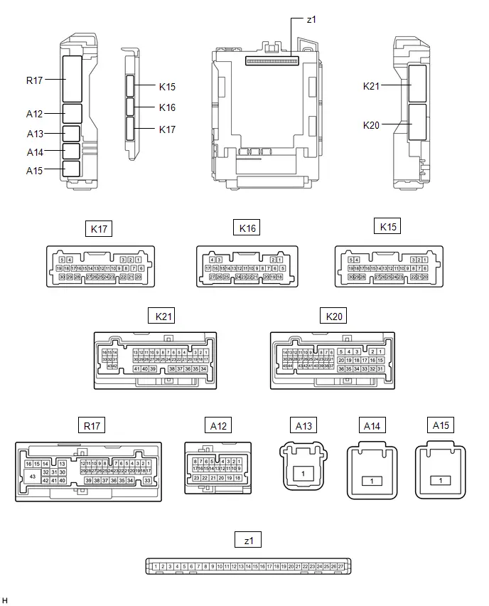
PARTS LOCATION
ILLUSTRATION
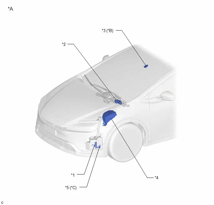
| *A | for LHD | *B | w/ Auto Wiper System |
| *C | w/ Level Warning Switch Assembly | - | - |
| *1 | WINDSHIELD WASHER MOTOR AND PUMP ASSEMBLY | *2 | WINDSHIELD WIPER MOTOR ASSEMBLY |
| *3 | RAIN SENSOR | *4 | NO. 1 ENGINE ROOM RELAY BLOCK AND NO. 1 JUNCTION BLOCK ASSEMBLY - WINDSHILD WIPER RELAY - IGP RELAY - WIPER FUSE - WASHER FUSE |
| *5 | LEVEL WARNING SWITCH ASSEMBLY | - | - |
ILLUSTRATION
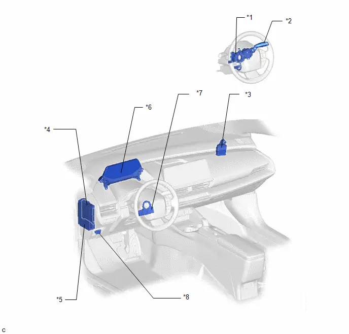
| *1 | STEERING WHEEL SWITCH HOUSING | *2 | WINDSHIELD WIPER SWITCH ASSEMBLY |
| *3 | WINDSHIELD WIPER RELAY ASSEMBLY | *4 | MAIN BODY ECU (MULTIPLEX NETWORK BODY ECU) |
| *5 | POWER DISTRIBUTION BOX ASSEMBLY - IGR NO. 1 RELAY - ECU-IGR NO. 3 FUSE | *6 | COMBINATION METER ASSEMBLY |
| *7 | STEERING SENSOR | *8 | DLC3 |
System Diagram
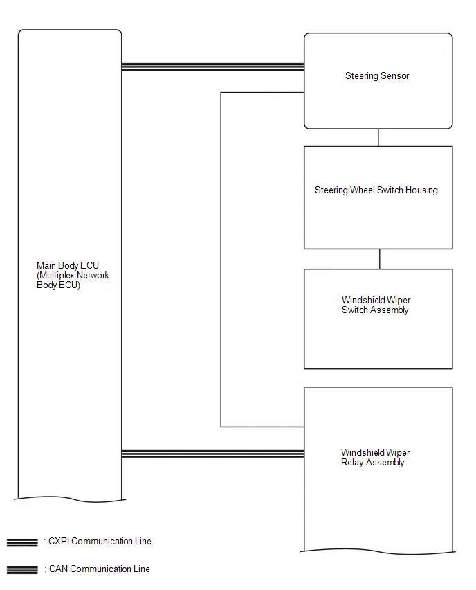
SYSTEM DIAGRAM
FRONT WIPER AND WASHER SYSTEM
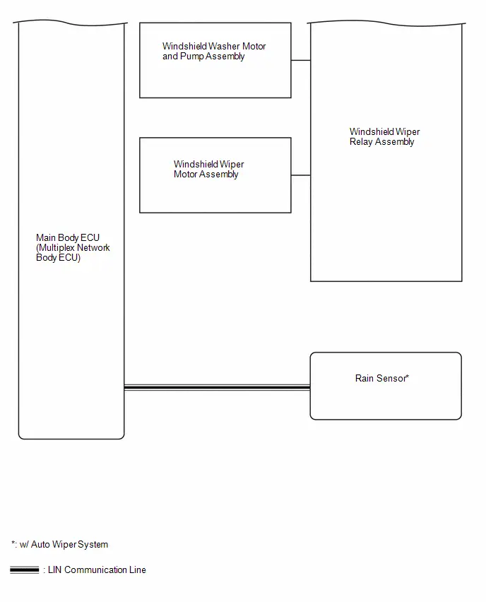
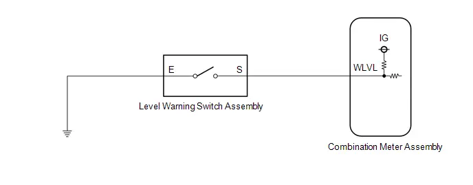
WASHER FLUID LEVEL WARNING SYSTEM(w/ Level Warning Switch Assembly)
How To Proceed With Troubleshooting
CAUTION / NOTICE / HINT
HINT:
- Use the following procedure to troubleshoot the wiper and washer system.
- *: Use the GTS.
PROCEDURE
| 1. | Toyota Prius Vehicle BROUGHT TO WORKSHOP |
|

| 2. | CUSTOMER PROBLEM ANALYSIS |
HINT:
- In troubleshooting, confirm that the problem symptoms have been accurately identified. Preconceptions should be discarded in order to make an accurate judgment. To clearly understand what the problem symptoms are, it is extremely important to ask the customer about the problem and the conditions at the time the malfunction occurred.
- Gather as much information as possible for reference. Past problems that seem unrelated may also help in some cases.
-
The following 5 items are important points for problem analysis:
What
Toyota Prius Vehicle model, system name
When
Date, time, occurrence frequency
Where
Road conditions
Under what conditions?
Driving conditions, weather conditions
How did it happen?
Problem symptoms
|

| 3. | PRE-CHECK |
(a) Measure the auxiliary battery voltage with ignition switch off.
Standard Voltage:
11 to 14 V
If the voltage is below 11 V, recharge or replace the auxiliary battery before proceeding to the next step.
(b) Check the fuses and relays.
(c) Check the connector connections and terminals to make sure that there are no abnormalities such as loose connections, deformation, etc.
|

| 4. | CHECK COMMUNICATION FUNCTION OF CAN COMMUNICATION SYSTEM* |
(a) Using the GTS, check for CAN communication system DTCs.
-
for HEV Model:
Click here

-
for PHEV Model:
Click here

| Result | Proceed to |
|---|---|
| CAN DTCs are not output | A |
| CAN DTCs are output | B |
| B |

| GO TO CAN COMMUNICATION SYSTEM
|


|

| 5. | CHECK FOR DTC* |
(a) Check for DTCs.
Body Electrical > Main Body > Trouble Codes| Result | Proceed to |
|---|---|
| DTCs are not output | A |
| DTCs are output | B |
| B |

| GO TO DIAGNOSTIC TROUBLE CODE CHART |
|

| 6. | PROBLEM SYMPTOMS TABLE |
(a) Refer to Problem Symptoms Table.
Click here

| Result | Proceed to |
|---|---|
| Fault is not listed in Problem Symptoms Table | A |
| Fault is listed in Problem Symptoms Table | B |
| B |

| GO TO PROBLEM SYMPTOMS TABLE |
|

| 7. | OVERALL ANALYSIS AND TROUBLESHOOTING* |
(a) Operation Check
Click here

(b) Customize Parameters
Click here

(c) Terminals of ECU
Click here

(d) Data List / Active Test
Click here

(e) Inspection
(f) On-Toyota Prius vehicle Inspection
|

| 8. | ADJUST, REPAIR OR REPLACE |
|

| 9. | CONFIRMATION TEST |
| NEXT |

| END |
Operation Check
OPERATION CHECK
CHECK FRONT WIPER CONTROL (w/ Auto Wiper System)
(a) Auto wiper function
(1) Continuously apply water to the windshield glass in front of the rain sensor.
(2) Turn the ignition switch to ON.
(3) Move the front wiper switch to the AUTO position.
(4) Check that the front wipers operate.
(b) Intermittent control function
HINT:
When the AUTO wiper function is disabled through a customize setting, the intermittent control function can be operated.
Click here

(1) Turn the ignition switch to ON.
(2) Move the front wiper switch to the AUTO position.
(3) Check that the intermittent operation interval can be adjusted between approximately 4 and 12.5 seconds by operating the auto sensitivity adjustment switch.
(c) Toyota Prius Vehicle speed sensing type adjustable intermittent wiper control function
HINT:
When the AUTO wiper function is disabled through a customize setting, the intermittent control function can be operated.
Click here

(1) Turn the ignition switch to ON.
(2) Move the front wiper switch to the AUTO position.
(3) Check that the intermittent operation interval changes between approximately 1.5 and 11 seconds according to the Toyota Prius vehicle speed and the position of the auto sensitivity adjustment switch.
(d) Door open linked wiper suspend function
(1) Continuously apply water to the windshield glass in front of the rain sensor.
(2) Turn the ignition switch to ON.
(3) Move the front wiper switch to the AUTO position and check that the front wipers operate.
(4) Open the driver door or front passenger door and check that the front wipers stop.
(5) Close the driver door or front passenger door and check that the front wipers re-operates.
CHECK FRONT WIPER CONTROL (w/o Auto Wiper System)
(a) Intermittent control function
(1) Turn the ignition switch to ON.
(2) Move the front wiper switch to the INT position.
(3) Check that the intermittent operation interval can be adjusted between approximately 4 and 12.5 seconds by operating the intermittent time adjustment switch.
(b) Toyota Prius Vehicle speed sensing type adjustable intermittent wiper control function
(1) Turn the ignition switch to ON.
(2) Move the front wiper switch to the INT position.
(3) Check that the intermittent operation interval changes between approximately 1.5 and 11 seconds according to the vehicle speed and the position of the intermittent time adjustment switch.
CHECK WASHER CONTROL
(a) Front washer cooperation
(1) Turn the ignition switch to ON.
(2) Hold the washer switch in the Fr WASH position for approximately 0.5 seconds or more and check that the front wipers operate in LO and washer fluid is sprayed.
(3) Release the washer switch and check that the front wipers operate for 3 cycles.
(b) Drip prevention wiper function
NOTICE:
Perform this inspection with the Toyota Prius vehicle stopped.
(1) Turn the ignition switch to ON.
(2) Operate the washers and check that approximately 3 seconds after front washer cooperation operates, the wipers operate 1 cycle.
CHECK REAR CAMERA WASHER SYSTEM (w/ Rear Camera Cleaner System)
(a) Combination switch
(1) Turn the ignition switch to ON.
(2) Hold the washer switch in the Rr WASH position and check that the rear television camera assembly is sprayed with washer fluid.
(b) Multimedia switch
(1) One push
- The rear camera washer operates for a certain amount of time.
(2) Pressed and held
- The rear camera washer operates while the multimedia switch is pressed and held.
LEVEL WARNING OPERATION INSPECTION(w/ Level Warning Switch Assembly)
(a) When the volume of washer fluid decreases to below a certain level (when the level warning switch is turned on), the multi-information display warns the driver by displaying a message.
Customize Parameters
CUSTOMIZE PARAMETERS
CUSTOMIZE WIPER AND WASHER SYSTEM
NOTICE:
- When the customer requests a change in a function, first make sure that the function can be customized.
- Be sure to make a note of the current settings before customizing.
- When troubleshooting a function, first make sure that the function is set to the default setting.
HINT:
The following items can be customized.
(a) Select the setting by referring to the table below.
Wiper| Tester Display | Description | Default | Setting | ECU |
|---|---|---|---|---|
| Auto Wiper Function | Function to enable AUTO wiper operation* | Avail | $00:Enable,$01:Disable | Main body ECU (Multiplex network body ECU) |
HINT:
- Changes to the customize settings will not be applied until the ignition switch is turned off then ON.
- *: w/ Auto Wiper System
| Tester Display | Description | Default | Setting | ECU |
|---|---|---|---|---|
| Wiper Voice Control Function | Function to enable the wiper-linked voice recognition operation function* | Enable | $00:Disable,$01:Enable | Main body ECU (Multiplex network body ECU) |
- *: w/ Body Device Voice Recognition Function
HINT:
Changes to the customize settings will not be applied until the ignition switch is turned off then ON.
Problem Symptoms Table
PROBLEM SYMPTOMS TABLE
NOTICE:
Before replacing the main body ECU (multiplex network body ECU), refer to Service Bulletin.
HINT:
- Use the table below to help determine the cause of problem symptoms. If multiple suspected areas are listed, the potential causes of the symptoms are listed in order of probability in the "Suspected Area" column of the table. Check each symptom by checking the suspected areas in the order they are listed. Replace parts as necessary.
- Inspect the fuses and relays related to this system before inspecting the suspected areas below.
| Symptom | Suspected Area | Link |
|---|---|---|
| Front wipers do not operate at all | Proceed to "Wiper and Washer Switch Circuit" |
|
| Proceed to "Front Wiper Motor Circuit" |
| |
| Main body ECU (Multiplex network body ECU) |
| |
| Windshield wiper relay assembly |
| |
| Front wipers do not operate in AUTO | Check customize parameters (Auto wiper) |
|
| Rain sensor tape (Check for air bubbles) | - | |
| Proceed to "Wiper and Washer Switch Circuit" |
| |
| Rain sensor |
| |
| Front wipers do not operate in LO | Proceed to "Wiper and Washer Switch Circuit" |
|
| Proceed to "Front Wiper Motor Circuit" |
| |
| Windshield wiper relay assembly |
| |
| Front wipers do not operate in HI | Proceed to "Wiper and Washer Switch Circuit" |
|
| Proceed to "Front Wiper Motor Circuit" |
| |
| Windshield wiper relay assembly |
| |
| Front wipers do not operate in INT* | Proceed to "Wiper and Washer Switch Circuit" |
|
| Front wipers do not operate in MIST | Proceed to "Wiper and Washer Switch Circuit" |
|
| Windshield wiper relay assembly |
| |
| When the front wipers are operating in AUTO, the rain sensor sensitivity cannot be adjusted by the auto sensitivity adjustment switch (wiping interval does not change) | Proceed to "Wiper and Washer Switch Circuit" |
|
| When the front wipers are operating in AUTO, the wiper interval does not change according to changes in the Toyota Prius vehicle speed | Rain sensor |
|
| Main body ECU (Multiplex network body ECU) |
| |
| When the front wipers are operating in INT, the front wiper intermittent operation interval cannot be adjusted by the auto sensitivity adjustment switch (wiping interval does not change)* | Proceed to "Wiper and Washer Switch Circuit" |
|
| When the front wipers are operating in INT, the front wiper intermittent operation interval does not change according to changes in the Toyota Prius vehicle speed* | Main body ECU (Multiplex network body ECU) |
|
| Front wipers continuously operate in AUTO | Proceed to "Wiper and Washer Switch Circuit" |
|
| Front wipers continuously operate in LO | Proceed to "Wiper and Washer Switch Circuit" |
|
| Front wipers continuously operate in HI | Proceed to "Wiper and Washer Switch Circuit" |
|
| Front wipers continuously operate in INT* | Proceed to "Wiper and Washer Switch Circuit" |
|
| When the customize setting "Auto Wiper" is changed, the operation of the wiper system does not change | Rain sensor |
|
| When the front wiper switch is turned off, the front wipers stop in the wrong position | Proceed to "Front Wiper Motor Circuit" |
|
| Check the automatic stop (park) position |
| |
| Windshield wiper relay assembly |
|


- *: When the customize setting "Auto Wiper" is set to "Not Avl".
| Symptom | Suspected Area | Link |
|---|---|---|
| Front wipers do not operate at all | Proceed to "Wiper and Washer Switch Circuit" |
|
| Proceed to "Front Wiper Motor Circuit" |
| |
| Main body ECU (Multiplex network body ECU) |
| |
| Windshield wiper relay assembly |
| |
| Front wipers do not operate in LO | Proceed to "Wiper and Washer Switch Circuit" |
|
| Proceed to "Front Wiper Motor Circuit" |
| |
| Windshield wiper relay assembly |
| |
| Front wipers do not operate in HI | Proceed to "Wiper and Washer Switch Circuit" |
|
| Proceed to "Front Wiper Motor Circuit" |
| |
| Windshield wiper relay assembly |
| |
| Front wipers do not operate in INT | Proceed to "Wiper and Washer Switch Circuit" |
|
| Proceed to "Front Wiper Motor Circuit" |
| |
| Windshield wiper relay assembly |
| |
| Front wipers do not operate in MIST | Proceed to "Wiper and Washer Switch Circuit" |
|
| Windshield wiper relay assembly |
| |
| When the front wiper switch is in INT, the front wiper intermittent operation interval cannot be adjusted by the intermittent time adjustment switch | Proceed to "Wiper and Washer Switch Circuit" |
|
| Main body ECU (Multiplex network body ECU) |
| |
| When the front wipers are operating in INT, the front wiper intermittent operation interval does not change according to changes in the Toyota Prius vehicle speed | Main body ECU (Multiplex network body ECU) |
|
| Front wipers continuously operate in LO | Proceed to "Wiper and Washer Switch Circuit" |
|
| Windshield wiper relay assembly |
| |
| Front wipers continuously operate in HI | Proceed to "Wiper and Washer Switch Circuit" |
|
| Windshield wiper relay assembly |
| |
| Front wipers continuously operate in INT | Proceed to "Wiper and Washer Switch Circuit" |
|
| Front wipers do not move to the service position (wiper operation is normal) | Main body ECU (Multiplex network body ECU) |
|
| When the front wiper switch is turned off, the front wipers do not move to the park position or stop in the wrong position | Proceed to "Front Wiper Motor Circuit" |
|
| Check the automatic stop (park) position |
| |
| Windshield wiper relay assembly |
|


| Symptom | Suspected Area | Link |
|---|---|---|
| Windshield washer motor and pump assembly does not operate | Proceed to "Wiper and Washer Switch Circuit" |
|
| Proceed to "Washer Motor Circuit" |
| |
| Windshield wiper relay assembly |
| |
| Front washers do not operate | Proceed to "Wiper and Washer Switch Circuit" |
|
| Windshield wiper relay assembly |
| |
| Washer fluid does not flow (Windshield washer motor and pump assembly is normal) | Washer fluid | - |
| Washer hose and nozzle | - |


| Symptom | Suspected Area | Link |
|---|---|---|
| Washer motor and pump assembly does not operate | Proceed to "Rear Cleaner Motor and Relay Circuit" |
|
| Proceed to "Wiper and Washer Switch Circuit" |
| |
| Main body ECU (multiplex network body ECU) |
| |
| Washer fluid does not flow (Washer motor and pump assembly is normal) | Washer fluid | - |
| Washer hose, camera cleaner nozzle | - |


| Symptom | Suspected Area | Link |
|---|---|---|
| "Windshield Washer Fluid Low" is displayed on the multi-information display when washer fluid level is not low | Proceed to "Washer Fluid Level Warning Switch Circuit" |
|
| "Windshield Washer Fluid Low" is not displayed on the multi-information display when washer fluid level is low | Washer fluid | - |
| Proceed to "Washer Fluid Level Warning Switch Circuit" |
|


Terminals Of Ecu
TERMINALS OF ECU
CHECK MAIN BODY ECU (MULTIPLEX NETWORK BODY ECU) AND POWER DISTRIBUTION BOX ASSEMBLY
(a) Remove the main body ECU (multiplex network body ECU) from the power distribution box assembly.
Click here


(b) Reconnect the power distribution box assembly connectors.
(c) Measure the voltage and check for pulses according to the value(s) in the table below.
| Terminal No. (Symbol) | Terminal Description | Condition | Specified Condition |
|---|---|---|---|
| z1-13 (GND1) - Body ground | Ground | Always | Below 1 Ω |
| z1-14 (GND2) - Body ground | Ground | Always | Below 1 Ω |
| z1-26 (BECU) - Body ground | Auxiliary battery power supply | Always | 11 to 14 V |
| z1-27 (IGR) - Body ground | IG power supply | Ignition switch off | Below 1 V |
| Ignition switch ON | 11 to 14 V | ||
| z1-22 - Body ground | CXPI communication line | Ignition switch off | Below 1 V |
| Ignition switch ON | Pulse generation | ||
| z1-15 (LIN2) - Body ground | LIN communication line | Ignition switch ON | Pulse generation |
(d) Connect the power distribution box assembly and main body ECU (multiplex network body ECU) connectors.
(e) Measure the voltage and check for pulses according to the value(s) in the table below.
| Terminal No. (Symbol) | Terminal Description | Condition | Specified Condition |
|---|---|---|---|
| K17-12 (WHI) - Body ground | Windshield wiper motor assembly HI operation signal | Windshield wiper motor and link assembly operating in LO | 9 to 14 V |
| Windshield wiper motor and link assembly operating in HI | Below 1 V | ||
| K16-11 (LIN4) - Body ground | LIN communication line | Ignition switch ON | Pulse generation |
| K17-6 (WPS) - Body ground | Wiper Relay operation signal | Ignition switch ON | 11 to 14 V |
| Less than approximately 60 seconds after ignition switch turned off | |||
| Approximately 60 seconds or more after ignition switch turned off | Below 1 V |

CHECK WINDSHIELD WIPER RELAY ASSEMBLY
(a) Disconnect the A55 and A56 windshield wiper relay assembly connectors.
(b) Measure the voltage and resistance according to the value(s) in the table below.
| Terminal No. (Symbol) | Terminal Description | Condition | Specified Condition |
|---|---|---|---|
| A55-3 (E) - Body ground | Ground | Always | Below 1 Ω |
| A55-5 (EWS) - Body ground | Ground | Always | Below 1 Ω |
| A55-6 (IGWS) - Body ground | Washer circuit IG power source | Ignition switch ON | 11 to 14 V |
| A55-8 ( B) - Body ground | Ignition switch ON signal (Power source circuit) | Ignition switch ON | 11 to 14 V |
| Less than approximately 60 seconds after ignition switch turned off | |||
| Approximately 60 seconds or more after ignition switch turned off | Below 1 V | ||
| A56-5 (ES) - Body ground | Ground | Always | Below 1 Ω |
(c) Connect the A55 and A56 windshield wiper relay assembly connectors.
(d) Measure the voltage and check for pulses according to the value(s) in the table below.
| Terminal No. (Symbol) | Terminal Description | Condition | Specified Condition |
|---|---|---|---|
| A55-1 ( WR) - Body ground | Front washer operation signal | Ignition switch ON, front washer operating | 11 to 14 V |
| A55-2 ( 1) - Body ground | LO operation signal to windshield wiper motor assembly | Ignition switch ON, windshield wiper motor assembly operating in LO | 11 to 14 V |
| A55-4 ( 2) - Body ground | HI operation signal to windshield wiper motor assembly | Ignition switch ON, windshield wiper motor assembly operating in HI | 11 to 14 V |
| A55-7 (-WR) - Body ground | Rear washer operation signal | Ignition switch ON, rear washer operating | 11 to 14 V |
| A56-3 (2S) - Body ground | Windshield wiper motor assembly HI operation signal | Approximately 60 seconds or more after ignition switch turned off | 4.5 to 5.5 V |
| Windshield wiper motor assembly operating in LO | 9 to 14 V | ||
| Windshield wiper motor assembly operating in HI | Below 1 V | ||
| A56-4 (MPX1) - Body ground | CXPI communication line | Ignition switch ON | Pulse generation |
| A56-6 ( SM) - Body ground | Windshield wiper motor assembly position detection signal | Windshield wiper motor assembly in LO or HI operation | Below 1 V ←→ 11 to 14 V |
| Windshield wiper motor assembly stopped | Below 1 V |

CHECK RAIN SENSOR (w/ Auto Wiper System)
(a) Disconnect the U4 rain sensor connector.
(b) Measure the voltage and resistance and check for pulses according to the value(s) in the table below.
| Terminal No. (Symbol) | Terminal Description | Condition | Specified Condition |
|---|---|---|---|
| U4-2 (ES) - Body ground | Ground | Always | Below 1 Ω |
| U4-3 (MPX) - Body ground | LIN communication signal | Ignition switch ON | Pulse generation |
| U4-4 (SIG) - Body ground | IG power source circuit | Ignition switch ON | 11 to 14 V |
Fail-safe Chart
FAIL-SAFE CHART
RAIN SENSOR FAIL-SAFE FUNCTION (w/ Auto Wiper System)
(a) The rain sensor performs fail-safe functions when it cannot properly receive necessary signals for wiper system control or a wiper system component is malfunctioning.
| Item | Fail-safe Function | Conditions to Return to Normal Condition |
|---|---|---|
| Rain sensor voltage is too low | Continues control according to the conditions detected before the malfunction | Rain sensor voltage returns to normal |
| The rain sensor temperature is excessively high (90°C (194°F) or higher) | Stops the wiper operation | Rain sensor returns to normal |
| The rain sensor temperature is excessively low (-15°C (5°F) or lower) | ||
| Rain sensor LIN communication error | LIN communication returns to normal | |
| Abnormal rain sensor signal | Performs intermittent operation according to the position of the auto sensitivity adjustment switch | Rain sensor returns to normal |
Data List / Active Test
DATA LIST / ACTIVE TEST
DATA LIST
NOTICE:
In the table below, the values listed under "Normal Condition" are reference values. Do not depend solely on these reference values when deciding whether a part is faulty or not.
HINT:
Using the GTS to read the Data List allows the values or states of switches, sensors, actuators and other items to be read without removing any parts. This non-intrusive inspection can be very useful because intermittent conditions or signals may be discovered before parts or wiring is disturbed. Reading the Data List information early in troubleshooting is one way to save diagnostic time.
(a) Read the Data List according to the display on the GTS.
Body Electrical > Main Body > Data List| Tester Display | Measurement Item | Range | Normal Condition | Diagnostic Note |
|---|---|---|---|---|
| Wiper Motor Cam Switch 1 | Front wiper stop position status | OFF or ON | OFF: Front wiper not at bottom of stroke ON: Front wiper at bottom of stroke | - |
| Wiper Control Switch HI | Front wiper switch HI position signal | OFF or ON | OFF: Front wiper switch not in HI position ON: Front wiper switch in HI position | - |
| Rain Sensor Status | Rain sensor temperature circuit condition | Normal or Error | Normal: Rain sensor is normal Error: Malfunction in rain sensor thermistor | w/ Auto Wiper System |
| Rain Sensor Level Status | Rain sensor output condition | Normal or Error | Normal: Rain sensor is normal Error: Malfunction in rain sensor thermistor output | w/ Auto Wiper System |
| Rain Sensor High Temperature Status | Rain sensor high temperature condition | Normal or Error | Normal: Rain sensor is normal Error: Rain sensor temperature is high | w/ Auto Wiper System |
| Rain Sensor Low Temperature Status | Rain sensor low temperature condition | Normal or Error | Normal: Rain sensor is normal Error: Rain sensor temperature is low | w/ Auto Wiper System |
| Wiper Switch Auto Signal | Windshield wiper switch assembly (AUTO position) condition | OFF or ON | OFF: Windshield wiper switch assembly not in AUTO position ON: Windshield wiper switch assembly in AUTO position | w/ Auto Wiper System |
| Wiper Operation Request (from other system) | Status of wiper operation request from other system | OFF or ON | OFF: Not requested ON: Requested | w/ Auto Wiper System |
| Wiper Motor Control Status | Wiper motor control condition in response to rain sensor request | Normal, Normal (Link Ctrl), Normal (Req Deny), Abnormal or Normal (Wiper Ctrl) | Current motor control condition | w/ Auto Wiper System |
| Wiper Intermittent Time Volume | Auto sensitivity adjustment volume condition | Shortest, Shorter, Longer or Longest | Shortest: Windshield wiper switch assembly (auto sensitivity adjustment volume condition) P4 position Shorter: Windshield wiper switch assembly (auto sensitivity adjustment volume condition) P3 position Longer: Windshield wiper switch assembly (auto sensitivity adjustment volume condition) P2 position Longest: Windshield wiper switch assembly (auto sensitivity adjustment volume condition) P1 position | * |
| Automatic Wiper Wiping Mode (Sensor to Wiper) | Status of command request signal for front wiper speed and intermittent time from rain sensor | Stop, LO Mode, HI Mode, Wait, INT Mode1 (Toyota Prius Vehicle Stop), INT Mode2 (Vehicle Stop), INT Mode3 (Vehicle Stop), INT Mode4 (Vehicle Stop), INT Mode5 (Vehicle Stop), INT Mode6 (Vehicle Stop), INT Mode7 (Vehicle Stop), INT Mode1 (Vehicle Run), INT Mode2 (Vehicle Run), INT Mode3 (Vehicle Run), INT Mode4 (Vehicle Run), INT Mode5 (Vehicle Run), INT Mode6 (Vehicle Run), INT Mode7 (Toyota Prius Vehicle Run), INT Mode (Sensor Abnormal), OFF (Customize) or Fail Stop | Stop: Windshield wiper switch assembly in AUTO position and stop requested (Windshield wiper switch assembly OFF included) (because rain not detected) LO Mode: Windshield wiper switch assembly in AUTO position and LO operation requested HI Mode: Windshield wiper switch assembly in AUTO position and HI operation requested Wait: Rain sensor is judging wiping mode INT Mode 1 (Toyota Prius Vehicle Stop): Windshield wiper switch assembly in AUTO position and intermittent operation requested of 32.7 s INT Mode 2 (Vehicle Stop): Windshield wiper switch assembly in AUTO position and intermittent operation requested of 17.5 s INT Mode 3 (Vehicle Stop): Windshield wiper switch assembly in AUTO position and intermittent operation requested of 9.7 s INT Mode 4 (Toyota Prius Vehicle Stop): Windshield wiper switch assembly in AUTO position and intermittent operation requested of 5.4 s INT Mode 5 (Vehicle Stop): Windshield wiper switch assembly in AUTO position and intermittent operation requested of 3.1 s INT Mode 6 (Vehicle Stop): Windshield wiper switch assembly in AUTO position and intermittent operation requested of 1.6 s INT Mode 7 (Toyota Prius Vehicle Stop): Windshield wiper switch assembly in AUTO position and intermittent operation requested of 0.8 s INT Mode 1 (Vehicle Run): Windshield wiper switch assembly in AUTO position and intermittent operation requested of 17.9 s INT Mode 2 (Vehicle Run): Windshield wiper switch assembly in AUTO position and intermittent operation requested of 10.1 s INT Mode 3 (Toyota Prius Vehicle Run): Windshield wiper switch assembly in AUTO position and intermittent operation requested of 5.9 s INT Mode 4 (Vehicle Run): Windshield wiper switch assembly in AUTO position and intermittent operation requested of 3.5 s INT Mode 5 (Vehicle Run): Windshield wiper switch assembly in AUTO position and intermittent operation requested of 2.1 s INT Mode 6 (Toyota Prius Vehicle Run): Windshield wiper switch assembly in AUTO position and intermittent operation requested of 1.2 s INT Mode 7 (Vehicle Run): Windshield wiper switch assembly in AUTO position and intermittent operation requested of 0.6 s INT Mode (Sensor Abnormal): Windshield wiper switch assembly in AUTO position and speed sensing intermittent operation requested OFF (Customize): Windshield wiper switch assembly in AUTO position and stop requested (for customization) Fail Stop: Windshield wiper switch assembly in AUTO position and stop requested (sensor malfunction) | w/ Auto Wiper System |
| Rain Sensor | Rain sensor detection information | With or Without | With: w/ Rain Sensor Without: w/o Rain Sensor | w/ Auto Wiper System |
| Wiper LO Single Operation Signal | Wiper LO single operation signal | With or Without | With: Windshield wiper switch assembly in AUTO position and sensor determines small amount of rain while wiper is in stopped position Without: Windshield wiper switch assembly in AUTO position and wiper in position other than stopped | w/ Auto Wiper System |
| Communication Wiper ECU | Connection status between windshield wiper motor assembly and main body ECU (multiplex network body ECU) | STOP or OK | STOP: Not Connected OK: Connected | Although this item is displayed on the GTS, it is not applicable to this Toyota Prius vehicle. |
| Communication Wiper Module | Connection status between windshield wiper relay assembly and main body ECU (multiplex network body ECU) | STOP or OK | STOP: Not Connected OK: Connected | DTCs are stored if a malfunction occurs in the CXPI communication system. |
| Communication Humidity/Rain Sensor | Connection status between rain sensor and main body ECU (multiplex network body ECU) | STOP or OK | STOP: Not Connected OK: Connected | w/ Auto Wiper System |
| R Wiper Stop Function at Back Door/Trunk Lid Open | Function to enable the back door open linked rear wiper suspend function | Enable or Disable | Customize setting displayed | Although this item is displayed on the GTS, it is not applicable to this Toyota Prius vehicle. |
| Auto Wiper Function | Function to enable the auto wiper function | Enable or Disable | Customize setting displayed | - |
| Wiper Voice Control Function | Function to enable the voice recognition function | Enable or Disable | Customize setting displayed | - |
-
*: Refer to Inspection for each position of the switch.
Click here

| Tester Display | Measurement Item | Range | Normal Condition | Diagnostic Note |
|---|---|---|---|---|
| Washer Level Warning Switch | Washer fluid level warning switch status | Washer Level Switch ON, Washer Level Switch OFF or Unknown | Washer Level Switch ON: Washer fluid level not low Washer Level Switch OFF: Washer fluid level low Unknown: Washer fluid level not detected | - |
| Wiper Switch | Front wiper switch OFF position signal | OFF or ON | OFF: Front wiper switch not in OFF position ON: Front wiper switch in OFF position | - |
| Wiper Switch (AUTO/INT) | Front wiper switch AUTO*1 or INT*2 position signal | OFF or ON | OFF: Front wiper switch not in AUTO*1 or INT*2 position ON: Front wiper switch in AUTO*1 or INT*2 position | - |
| Wiper Switch (LO) | Front wiper switch LO position signal | OFF or ON | OFF: Front wiper switch not in LO position ON: Front wiper switch in LO position | - |
| Wiper Switch (HI) | Front wiper switch HI position signal | OFF or ON | OFF: Front wiper switch not in HI position ON: Front wiper switch in HI position | - |
| Wiper Switch (MIST) | Front wiper switch MIST position signal | OFF or ON | OFF: Front wiper switch not in MIST position ON: Front wiper switch in MIST position | - |
| Washer Switch | Washer switch Fr WASH position signal | OFF or ON | OFF: Washer switch not in Fr WASH position ON: Washer switch in Fr WASH position | - |
| Wiper Switch (Intermittent) | Front wiper switch INT position signal | OFF or ON | OFF: Front wiper switch not in INT ON: Front wiper switch in INT | *2 |
| Rear Wiper Switch | Rear wiper switch position signal | OFF or ON | OFF: Rear wiper switch not in ON position ON: Rear wiper switch in ON position | Although this item is displayed on the GTS, it is not applicable to this Toyota Prius vehicle. |
| Rear Washer Switch | Washer switch Rr WASH position signal | OFF or ON | OFF: Washer switch not in Rr WASH position ON: Washer switch in Rr WASH position | *3 |
| Wiper Speed (FAST) | Intermittent time adjustment volume condition | OFF or ON | OFF: Windshield wiper switch assembly (auto sensitivity adjustment volume condition) not in P4 position ON: Windshield wiper switch assembly (auto sensitivity adjustment volume condition) in P4 position | *4 |
| Wiper Speed (2nd FAST) | Intermittent time adjustment volume condition | OFF or ON | OFF: Windshield wiper switch assembly (auto sensitivity adjustment volume condition) not in P3 position ON: Windshield wiper switch assembly (auto sensitivity adjustment volume condition) in P3 position | *4 |
| Wiper Speed (3rd FAST) | Intermittent time adjustment volume condition | OFF or ON | OFF: Windshield wiper switch assembly (auto sensitivity adjustment volume condition) not in P2 position ON: Windshield wiper switch assembly (auto sensitivity adjustment volume condition) in P2 position | *4 |
| Wiper Speed (SLOW) | Intermittent time adjustment volume condition | OFF or ON | OFF: Windshield wiper switch assembly (auto sensitivity adjustment volume condition) not in P1 position ON: Windshield wiper switch assembly (auto sensitivity adjustment volume condition) in P1 position | *4 |
- *1: w/ Auto Wiper System
- *2: w/o Auto Wiper System
- *3: w/ Rear Camera Cleaner System
-
*4: Refer to Inspection for each position of the switch.
Click here

ACTIVE TEST
HINT:
Using the GTS to perform Active Tests allows relays, VSVs, actuators and other items to be operated without removing any parts. This non-intrusive functional inspection can be very useful because intermittent operation may be discovered before parts or wiring is disturbed. Performing Active Tests early in troubleshooting is one way to save diagnostic time. Data List information can be displayed while performing Active Tests.
(a) Perform the Active Test according to the display on the GTS.
Body Electrical > Main Body > Active Test| Tester Display | Measurement Item | Control Range | Diagnostic Note |
|---|---|---|---|
| Wiper Power Relay | Function to operate the windshield wiper relay | OFF or ON | - |
| Front Washer Relay | Function to operate the windshield washer motor and pump assembly (Front) | OFF or ON | - |
| Front Wiper Lo Operation | Function to operate the windshield wiper motor assembly in LO | OFF or ON | - |
| Front Wiper Hi Operation | Function to operate the windshield wiper motor assembly in HI | OFF or ON | - |
| Rear Washer Relay | Function to operate the windshield washer motor and pump assembly (Rear) | OFF or ON | - |
Humidity/Rain Sensor Missing Message (B127987)
DESCRIPTION
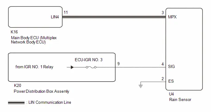
The main body ECU (multiplex network body ECU) and rain sensor communicate via LIN communication. The main body ECU (multiplex network body ECU) stores this DTC if communication becomes abnormal.
| DTC No. | Detection Item | DTC Detection Condition | Trouble Area | Memory | DTC Output from | Priority |
|---|---|---|---|---|---|---|
| B127987 | Humidity/Rain Sensor Missing Message | Detection Condition:
Malfunction Status:
Malfunction Duration:
|
| ○ | Main Body | A |
WIRING DIAGRAM
CAUTION / NOTICE / HINT
NOTICE:
- Inspect the fuses for circuits related to this system before performing the following procedure.
- Before replacing the main body ECU (multiplex network body ECU), refer to Service Bulletin.
PROCEDURE
| 1. | CHECK FOR DTC |
(a) Check for DTCs.
Body Electrical > Main Body > Trouble Codes| Result | Proceed to |
|---|---|
| Only B127987 is output | A |
| B127987 and B276C88 are output | B |
| B |

| GO TO DTC B276C88 |
|

| 2. | CHECK HARNESS AND CONNECTOR (MAIN BODY ECU (MULTIPLEX NETWORK BODY ECU) - RAIN SENSOR) |
Pre-procedure1
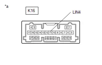
(a) Disconnect the K16 main body ECU (multiplex network body ECU) connector.
(b) Disconnect the U4 rain sensor connector.
Procedure1
(c) Measure the resistance according to the value(s) in the table below.
Standard Resistance:
 Click Location & Routing(K16,U4) Click Connector(K16) Click Connector(U4)
 | Tester Connection | Condition | Specified Condition | Result |
|---|---|---|---|
| K16-11 (LIN4) - U4-3 (MPX) | Always | Below 1 Ω | Ω |
Post-procedure1
(d) None
| NG |

| REPAIR OR REPLACE HARNESS OR CONNECTOR |
|

| 3. | CHECK MAIN BODY ECU (MULTIPLEX NETWORK BODY ECU) |
| (a) Check for pulses according to the value(s) in the table below. Standard Pulse:  Click Location & Routing(K16) Click Connector(K16) Click Location & Routing(K16) Click Connector(K16)
|
|
| NG |

| REPLACE MAIN BODY ECU (MULTIPLEX NETWORK BODY ECU)
|


|

| 4. | CHECK HARNESS AND CONNECTOR (POWER SOURCE - RAIN SENSOR) |
(a) Measure the voltage according to the value(s) in the table below.
Standard Voltage:
 Click Location & Routing(U4) Click Connector(U4)
 | Tester Connection | Condition | Specified Condition | Result |
|---|---|---|---|
| U4-4 (SIG) - Body ground | Ignition switch ON | 11 to 14 V | V |
| NG |

| REPAIR OR REPLACE HARNESS OR CONNECTOR |
|

| 5. | CHECK HARNESS AND CONNECTOR (RAIN SENSOR - BODY GROUND) |
(a) Measure the resistance according to the value(s) in the table below.
Standard Resistance:
 Click Location & Routing(U4) Click Connector(U4)
 | Tester Connection | Condition | Specified Condition | Result |
|---|---|---|---|
| U4-2 (ES) - Body ground | Always | Below 1 Ω | Ω |
| OK |

| REPLACE RAIN SENSOR |
| NG |

| REPAIR OR REPLACE HARNESS OR CONNECTOR |
Rain Sensor Component Internal Failure (B140096)
DESCRIPTION
This DTC is stored when the rain sensor detects an internal malfunction.
| DTC No. | Detection Item | DTC Detection Condition | Trouble Area | Memory | DTC Output from | Priority |
|---|---|---|---|---|---|---|
| B140096 | Rain Sensor Component Internal Failure | Detection Condition:
Malfunction Status:
| Rain sensor | ○ | Main Body | A |
PROCEDURE
| 1. | CLEAR DTC |
(a) Clear the DTCs.
Body Electrical > Main Body > Clear DTCs
|

| 2. | CHECK FOR DTC |
(a) Read the DTCs.
Body Electrical > Main Body > Trouble Codes| Result | Proceed to |
|---|---|
| B140096 is not output | A |
| B140096 is output | B |
| A |

| USE SIMULATION METHOD TO CHECK |
| B |

| REPLACE RAIN SENSOR |
Wiper Module Missing Message (B235787)
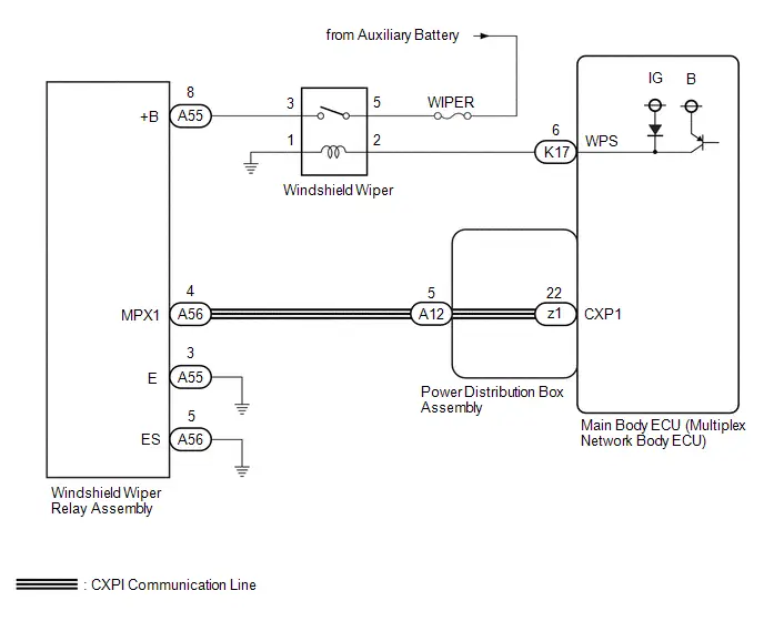
DESCRIPTION
The main body ECU (multiplex network body ECU) and windshield wiper relay assembly communicate via CXPI communication. The main body ECU (multiplex network body ECU) stores this DTC if communication becomes abnormal.
| DTC No. | Detection Item | DTC Detection Condition | Trouble Area | Memory | DTC Output from | Priority |
|---|---|---|---|---|---|---|
| B235787 | Wiper Module Missing Message | Detection condition:
Malfunction Status:
Malfunction Time:
|
| ○ | Main Body | A |
WIRING DIAGRAM
CAUTION / NOTICE / HINT
NOTICE:
- Inspect the fuses of circuits related to this system before performing the following procedure.
- Before replacing the main body ECU (multiplex network body ECU), refer to Service Bulletin.
PROCEDURE
| 1. | CHECK HARNESS AND CONNECTOR (WINDSHIELD WIPER RELAY ASSEMBLY - MAIN BODY ECU (MULTIPLEX NETWORK BODY ECU)) |
Pre-procedure1
(a) Disconnect the A56 windshield wiper relay assembly connector.
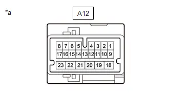
(b) Disconnect the A12 power distribution box assembly connector.
Procedure1
(c) Measure the resistance according to the value(s) in the table below.
Standard Resistance:
 Click Location & Routing(A56,A12) Click Connector(A56) Click Connector(A12)
 | Tester Connection | Condition | Specified Condition |
|---|---|---|
| A56-4 (MPX1) - A12-5 | Always | Below 1 Ω |
| A56-4 (MPX1) or A12-5 - Body ground | Always | 10 kΩ or higher |
Post-procedure1
(d) None
| NG |

| REPAIR OR REPLACE HARNESS OR CONNECTOR |
|

| 2. | CHECK MAIN BODY ECU (MULTIPLEX NETWORK BODY ECU) |
| (a) Check for voltage and pulses according to the value(s) in the table below. Standard Voltage and Pulse:  Click Location & Routing(A12) Click Connector(A12) Click Location & Routing(A12) Click Connector(A12)
|
|
| NG |

| GO TO STEP 12 |
|

| 3. | PERFORM ACTIVE TEST USING GTS |
(a) Perform the Active Test according to the display on the GTS.
Body Electrical > Main Body > Active Test| Tester Display | Measurement Item | Control Range | Diagnostic Note |
|---|---|---|---|
| Wiper Power Relay | Function to operate the Windshield Wiper relay | OFF or ON | - |
| Tester Display |
|---|
| Wiper Power Relay |
OK:
Windshield Wiper relay operates normally.
| NG |

| GO TO STEP 9 |
|

| 4. | CHECK HARNESS AND CONNECTOR (WINDSHIELD WIPER RELAY ASSEMBLY - BODY GROUND) |
Pre-procedure1
(a) Disconnect the A55 windshield wiper relay assembly connector.
Procedure1
(b) Measure the resistance according to the value(s) in the table below.
Standard Resistance:
 Click Location & Routing(A55,A56) Click Connector(A55) Click Connector(A56)
 | Tester Connection | Condition | Specified Condition |
|---|---|---|
| A55-3 (E) - Body ground | Always | Below 1 Ω |
| A56-5 (ES) - Body ground | Always | Below 1 Ω |
Post-procedure1
(c) None
| NG |

| REPAIR OR REPLACE HARNESS OR CONNECTOR |
|

| 5. | CHECK HARNESS AND CONNECTOR (POWER SOURCE - WINDSHIELD WIPER RELAY ASSEMBLY) |
(a) Measure the voltage according to the value(s) in the table below.
Standard Voltage:
 Click Location & Routing(A55) Click Connector(A55)
 | Tester Connection | Condition | Specified Condition |
|---|---|---|
| A55-8 ( B) - Body ground | Ignition switch ON | 11 to 14 V |
| Less than approximately 60 seconds after ignition switch turned off | 11 to 14 V | |
| Approximately 60 seconds or more after ignition switch turned off | Below 1 V |
| OK |

| REPLACE WINDSHIELD WIPER RELAY ASSEMBLY
|


|

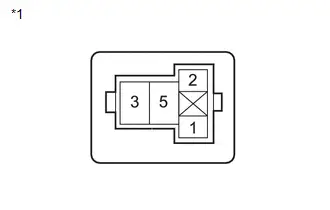
| 6. | INSPECT WINDSHIELD WIPER RELAY |
HINT:
Click here

| NG |

| REPLACE WINDSHIELD WIPER RELAY |
|

| 7. | CHECK HARNESS AND CONNECTOR (POWER SOURCE - WINDSHIELD WIPER RELAY) |
| (a) Measure the voltage according to the value(s) in the table below. Standard Voltage:
|
|

| NG |

| REPAIR OR REPLACE HARNESS OR CONNECTOR |
|

| 8. | CHECK HARNESS AND CONNECTOR (WINDSHIELD WIPER RELAY ASSEMBLY - WINDSHIELD WIPER RELAY) |
(a) Measure the resistance according to the value(s) in the table below.
Standard Resistance:
 Click Location & Routing(A55) Click Connector(A55)
 | Tester Connection | Condition | Specified Condition |
|---|---|---|
| A55-8 ( B) - 3 (Windshield Wiper Relay) | Always | Below 1 Ω |
| A55-8 ( B) or 3 (Windshield Wiper Relay) - Body ground | Always | 10 kΩ or higher |
| OK |

| REPLACE MAIN BODY ECU (MULTIPLEX NETWORK BODY ECU)
|


| NG |

| REPAIR OR REPLACE HARNESS OR CONNECTOR |
| 9. | INSPECT WINDSHIELD WIPER RELAY |
HINT:
Click here

| NG |

| REPLACE WINDSHIELD WIPER RELAY |
|

| 10. | CHECK HARNESS AND CONNECTOR (WINDSHIELD WIPER RELAY - MAIN BODY ECU (MULTIPLEX NETWORK BODY ECU)) |
Pre-procedure1
(a) Disconnect the K17 main body ECU (multiplex network body ECU) connector.
Procedure1
| (b) Measure the resistance according to the value(s) in the table below. Standard Resistance:  Click Location & Routing(K17) Click Connector(K17) Click Location & Routing(K17) Click Connector(K17)
Result:
|
|
Post-procedure1
(c) None
| NG |

| REPAIR OR REPLACE HARNESS OR CONNECTOR |
|

| 11. | CHECK HARNESS AND CONNECTOR (WINDSHIELD WIPER RELAY - BODY GROUND) |
(a) Measure the resistance according to the value(s) in the table below.
Standard Resistance:
| Tester Connection | Condition | Specified Condition |
|---|---|---|
| 1 (Windshield Wiper Relay) - Body ground | Always | Below 1 Ω |
| OK |

| REPLACE MAIN BODY ECU (MULTIPLEX NETWORK BODY ECU)
|


| NG |

| REPAIR OR REPLACE HARNESS OR CONNECTOR |
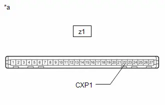
| 12. | CHECK POWER DISTRIBUTION BOX ASSEMBLY |
Pre-procedure1
(a) Remove the main body ECU (multiplex network body ECU) from the power distribution box assembly.
HINT:
Click here


Procedure1
| (b) Measure the resistance according to the value(s) in the table below. Standard Resistance:  Click Location & Routing(A12,z1) Click Connector(A12) Click Connector(z1) Click Location & Routing(A12,z1) Click Connector(A12) Click Connector(z1)
Result: Pre-procedure1
|
|
Post-procedure1
(c) None
| OK |

| REPLACE MAIN BODY ECU (MULTIPLEX NETWORK BODY ECU)
|


| NG |

| REPLACE POWER DISTRIBUTION BOX ASSEMBLY
|


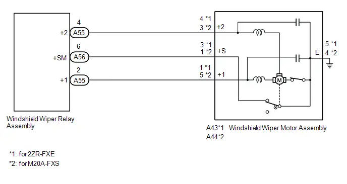
Front Wiper Motor Circuit
DESCRIPTION
The windshield wiper relay assembly controls the windshield wiper motor assembly through this circuit.
WIRING DIAGRAM
PROCEDURE
| 1. | PERFORM ACTIVE TEST USING GTS |
(a) Perform the Active Test according to the display on the GTS.
Body Electrical > Main Body > Active Test| Tester Display | Measurement Item | Control Range | Diagnostic Note |
|---|---|---|---|
| Front Wiper Lo Operation | Function to operate the windshield wiper motor assembly in LO | OFF or ON | - |
| Front Wiper Hi Operation | Function to operate the windshield wiper motor assembly in HI | OFF or ON | - |
| Tester Display |
|---|
| Front Wiper Lo Operation |
| Tester Display |
|---|
| Front Wiper Hi Operation |
OK:
Windshield wiper motor assembly operates normally.
| OK |

| PROCEED TO NEXT SUSPECTED AREA SHOWN IN PROBLEM SYMPTOMS TABLE |
|

| 2. | INSPECT WINDSHIELD WIPER MOTOR ASSEMBLY |
(a) Remove the windshield wiper motor assembly.
Click here

(b) Inspect the windshield wiper motor assembly.
Click here

| NG |

| REPLACE WINDSHIELD WIPER MOTOR ASSEMBLY |
|

| 3. | CHECK HARNESS AND CONNECTOR (WINDSHIELD WIPER RELAY ASSEMBLY - WINDSHIELD WIPER MOTOR ASSEMBLY) |
(a) Disconnect the A55 and A56 windshield wiper relay assembly connectors.
(b) Measure the resistance according to the value(s) in the table below.
Standard Resistance:
for 2ZR-FXE Click Location & Routing(A55,A43,A56) Click Connector(A55) Click Connector(A43) Click Connector(A56)
 | Tester Connection | Condition | Specified Condition |
|---|---|---|
| A55-2 ( 1) - A43-1 ( 1) | Always | Below 1 Ω |
| A55-4 ( 2) - A43-4 ( 2) | Always | Below 1 Ω |
| A56-6 ( SM) - A43-3 ( S) | Always | Below 1 Ω |
| A55-2 ( 1) or A43-1 ( 1) - Body ground | Always | 10 kΩ or higher |
| A55-4 ( 2) or A43-4 ( 2) - Body ground | Always | 10 kΩ or higher |
| A56-6 ( SM) or A43-3 ( S) - Body ground | Always | 10 kΩ or higher |
Standard Resistance:
for M20A-FXS Click Location & Routing(A55,A44,A56) Click Connector(A55) Click Connector(A44) Click Connector(A56)
 | Tester Connection | Condition | Specified Condition |
|---|---|---|
| A55-2 ( 1) - A44-5 ( 1) | Always | Below 1 Ω |
| A55-4 ( 2) - A44-3 ( 2) | Always | Below 1 Ω |
| A56-6 ( SM) - A44-1 ( S) | Always | Below 1 Ω |
| A55-2 ( 1) or A44-5 ( 1) - Body ground | Always | 10 kΩ or higher |
| A55-4 ( 2) or A44-3 ( 2) - Body ground | Always | 10 kΩ or higher |
| A56-6 ( SM) or A44-1 ( S) - Body ground | Always | 10 kΩ or higher |
| NG |

| REPAIR OR REPLACE HARNESS OR CONNECTOR |
|

| 4. | CHECK HARNESS AND CONNECTOR (WINDSHIELD WIPER MOTOR ASSEMBLY - BODY GROUND) |
(a) Measure the resistance according to the value(s) in the table below.
Standard Resistance:
for 2ZR-FXE Click Location & Routing(A43) Click Connector(A43)
 | Tester Connection | Condition | Specified Condition |
|---|---|---|
| A43-5 (E) - Body ground | Always | Below 1 Ω |
Standard Resistance:
for M20A-FXS Click Location & Routing(A44) Click Connector(A44)
 | Tester Connection | Condition | Specified Condition |
|---|---|---|
| A44-4 (E) - Body ground | Always | Below 1 Ω |
| OK |

| REPLACE WINDSHIELD WIPER RELAY ASSEMBLY
|


| NG |

| REPAIR OR REPLACE HARNESS OR CONNECTOR |
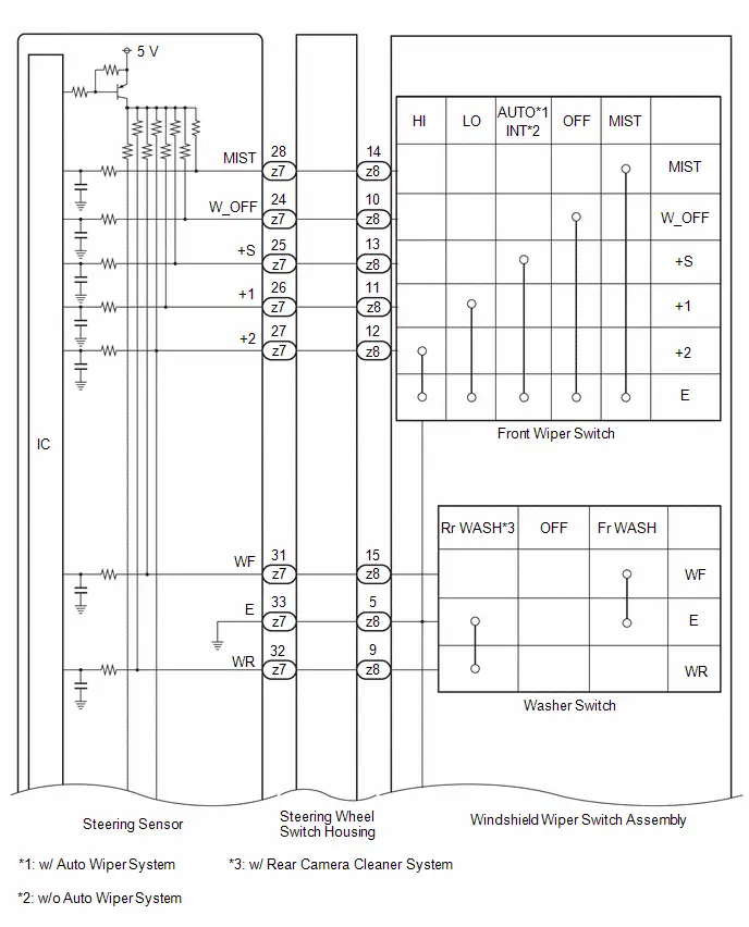
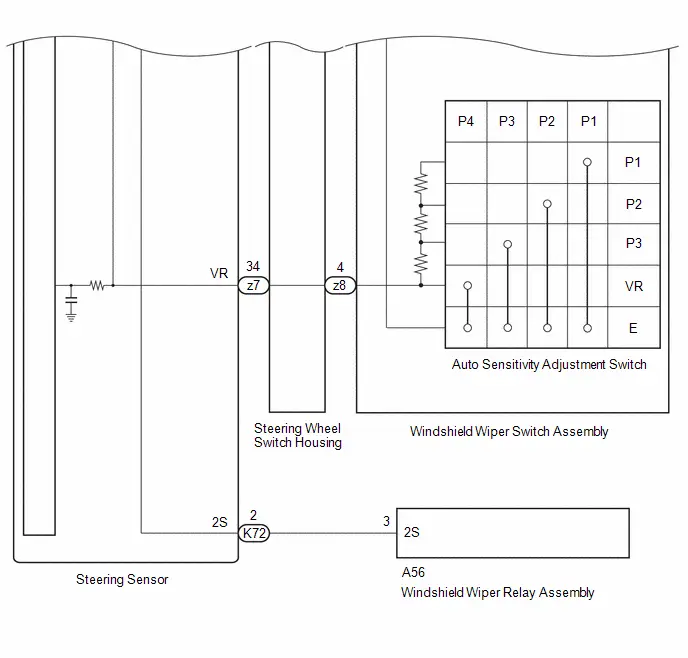
Wiper and Washer Switch Circuit
DESCRIPTION
The condition of the windshield wiper switch assembly is detected and sent to the steering sensor in this circuit.
WIRING DIAGRAM
PROCEDURE
| 1. | READ VALUE USING GTS |
(a) Read the Data List according to the display on the GTS.
Body Electrical > Combination Meter > Data List| Tester Display | Measurement Item | Range | Normal Condition | Diagnostic Note |
|---|---|---|---|---|
| Wiper Switch | Front wiper switch OFF position signal | OFF or ON | OFF: Front wiper switch not in OFF position ON: Front wiper switch in OFF position | - |
| Wiper Switch (AUTO/INT) | Front wiper switch AUTO*1 or INT*2 position signal | OFF or ON | OFF: Front wiper switch not in AUTO*1 or INT*2 position ON: Front wiper switch in AUTO*1 or INT*2 position | - |
| Wiper Switch (LO) | Front wiper switch LO position signal | OFF or ON | OFF: Front wiper switch not in LO position ON: Front wiper switch in LO position | - |
| Wiper Switch (HI) | Front wiper switch HI position signal | OFF or ON | OFF: Front wiper switch not in HI position ON: Front wiper switch in HI position | - |
| Wiper Switch (MIST) | Front wiper switch MIST position signal | OFF or ON | OFF: Front wiper switch not in MIST position ON: Front wiper switch in MIST position | - |
| Washer Switch | Washer switch Fr WASH position signal | OFF or ON | OFF: Washer switch not in Fr WASH position ON: Washer switch in Fr WASH position | - |
| Wiper Switch (Intermittent) | Front wiper switch INT position signal | OFF or ON | OFF: Front wiper switch not in INT ON: Front wiper switch in INT | *2 |
| Rear Wiper Switch | Rear wiper switch position signal | OFF or ON | OFF: Rear wiper switch not in ON position ON: Rear wiper switch in ON position | Although this item is displayed on the GTS, it is not applicable to this Toyota Prius vehicle. |
| Rear Washer Switch | Washer switch Rr WASH position signal | OFF or ON | OFF: Washer switch not in Rr WASH position ON: Washer switch in Rr WASH position | - |
| Wiper Speed (FAST) | Intermittent time adjustment volume condition | OFF or ON | OFF: Windshield wiper switch assembly (auto sensitivity adjustment volume condition) not in P4 position ON: Windshield wiper switch assembly (auto sensitivity adjustment volume condition) in P4 position | *3 |
| Wiper Speed (2nd FAST) | Intermittent time adjustment volume condition | OFF or ON | OFF: Windshield wiper switch assembly (auto sensitivity adjustment volume condition) not in P3 position ON: Windshield wiper switch assembly (auto sensitivity adjustment volume condition) in P3 position | *3 |
| Wiper Speed (3rd FAST) | Intermittent time adjustment volume condition | OFF or ON | OFF: Windshield wiper switch assembly (auto sensitivity adjustment volume condition) not in P2 position ON: Windshield wiper switch assembly (auto sensitivity adjustment volume condition) in P2 position | *3 |
| Wiper Speed (SLOW) | Intermittent time adjustment volume condition | OFF or ON | OFF: Windshield wiper switch assembly (auto sensitivity adjustment volume condition) not in P1 position ON: Windshield wiper switch assembly (auto sensitivity adjustment volume condition) in P1 position | *3 |
- *1: w/ Auto Wiper System
- *2: w/o Auto Wiper System
-
*3: Refer to Inspection for each position of the switch.
Click here

| Tester Display |
|---|
| Wiper Switch |
| Wiper Switch (AUTO/INT) |
| Wiper Switch (LO) |
| Wiper Switch (HI) |
| Wiper Switch (MIST) |
| Washer Switch |
| Wiper Switch (Intermittent) |
| Rear Wiper Switch |
| Rear Washer Switch |
| Wiper Speed (FAST) |
| Wiper Speed (2nd FAST) |
| Wiper Speed (3rd FAST) |
| Wiper Speed (SLOW) |
OK:
The GTS display changes correctly in response to the windshield wiper switch assembly operation.
| OK |

| PROCEED TO NEXT SUSPECTED AREA SHOWN IN PROBLEM SYMPTOMS TABLE |
|

| 2. | INSPECT WINDSHIELD WIPER SWITCH ASSEMBLY |
(a) Remove the windshield wiper switch assembly.
Click here


(b) Inspect the windshield wiper switch assembly.
Click here

| NG |

| REPLACE WINDSHIELD WIPER SWITCH ASSEMBLY
|


|

| 3. | INSPECT STEERING WHEEL SWITCH HOUSING |
(a) Remove the steering wheel switch housing.
Click here


(b) Inspect the steering wheel switch housing.
Click here

| NG |

| REPLACE STEERING WHEEL SWITCH HOUSING
|


|

| 4. | CHECK HARNESS AND CONNECTOR (STEERING SENSOR - WINDSHIELD WIPER RELAY ASSEMBLY) |
(a) Disconnect the A56 windshield wiper relay assembly connector.
(b) Measure the resistance according to the value(s) in the table below.
Standard Resistance:
 Click Location & Routing(K72,A56) Click Connector(K72) Click Connector(A56)
 | Tester Connection | Condition | Specified Condition |
|---|---|---|
| K72-2 (2S) - A56-3 (2S) | Always | Below 1 Ω |
| K72-2 (2S) or A56-3 (2S) - Body ground | Always | 10 kΩ or higher |
| OK |

| REPLACE WINDSHIELD WIPER RELAY ASSEMBLY
|


| NG |

| REPAIR OR REPLACE HARNESS OR CONNECTOR |
Rear Cleaner Motor and Relay Circuit
DESCRIPTION
When the main body ECU (multiplex network body ECU) receives a washer switch (Rr CAMERA WASH) signal from the windshield wiper switch assembly, the windshield washer motor and pump assembly operates to spray the windshield washer.
WIRING DIAGRAM
Click here

CAUTION / NOTICE / HINT
NOTICE:
-
First check that the windshield washer function operates normally.
Click here

- Inspect the fuses for circuits related to this system before performing the following procedure.
- If the main body ECU (multiplex network body ECU) is replaced, refer to Service Bulletin.
PROCEDURE
| 1. | PERFORM ACTIVE TEST USING GTS |
(a) Perform the Active Test according to the display on the GTS.
Click here

| Tester Display | Measurement Item | Control Range | Diagnostic Note |
|---|---|---|---|
| Rear Washer Relay | Operates the windshield washer motor and pump assembly | OFF or ON | - |
| Tester Display |
|---|
| Rear Washer Relay |
OK:
The windshield washer motor and pump assembly is operate normally.
| OK |

| PROCEED TO NEXT SUSPECTED AREA SHOWN IN PROBLEM SYMPTOMS TABLE |
|

| 2. | INSPECT WINDSHIELD WASHER MOTOR AND PUMP ASSEMBLY |
(a) Remove the windshield washer motor and pump assembly.
Click here

(b) Inspect the windshield washer motor and pump assembly.
Click here

| NG |

| REPLACE WINDSHIELD WASHER MOTOR AND PUMP ASSEMBLY |
|

| 3. | CHECK HARNESS AND CONNECTOR (POWER SOURCE - WINDSHIELD WIPER RELAY ASSEMBLY) |
(a) Disconnect the A55 windshield wiper relay assembly connector.
(b) Measure the voltage according to the value(s) in the table below.
Standard Voltage:
 Click Location & Routing(A55) Click Connector(A55)
 | Tester Connection | Condition | Specified Condition |
|---|---|---|
| A55-6 (IGWS) - Body ground | Ignition switch ON | 11 to 14 V |
| NG |

| REPAIR OR REPLACE HARNESS OR CONNECTOR |
|

| 4. | CHECK HARNESS AND CONNECTOR (WINDSHIELD WIPER RELAY ASSEMBLY - BODY GROUND) |
(a) Measure the resistance according to the value(s) in the table below.
Standard Resistance:
 Click Location & Routing(A55) Click Connector(A55)
 | Tester Connection | Condition | Specified Condition |
|---|---|---|
| A55-5 (EWS) - Body ground | Always | Below 1 Ω |
| NG |

| REPAIR OR REPLACE HARNESS OR CONNECTOR |
|

| 5. | CHECK HARNESS AND CONNECTOR (WINDSHIELD WIPER RELAY ASSEMBLY - WINDSHIELD WASHER MOTOR AND PUMP ASSEMBLY) |
(a) Measure the resistance according to the value(s) in the table below.
Standard Resistance:
 Click Location & Routing(A55,A46) Click Connector(A55) Click Connector(A46)
 | Tester Connection | Condition | Specified Condition |
|---|---|---|
| A55-1 ( WR) - A46-1 (B) | Always | Below 1 Ω |
| A55-7 (-WR) - A46-2 (SW) | Always | Below 1 Ω |
| A55-1 ( WR) or A46-1 (B) - Body ground | Always | 10 kΩ or higher |
| A55-7 (-WR) or A46-2 (SW) - Body ground | Always | 10 kΩ or higher |
| OK |

| REPLACE WINDSHIELD WIPER RELAY ASSEMBLY
|


| NG |

| REPAIR OR REPLACE HARNESS OR CONNECTOR |
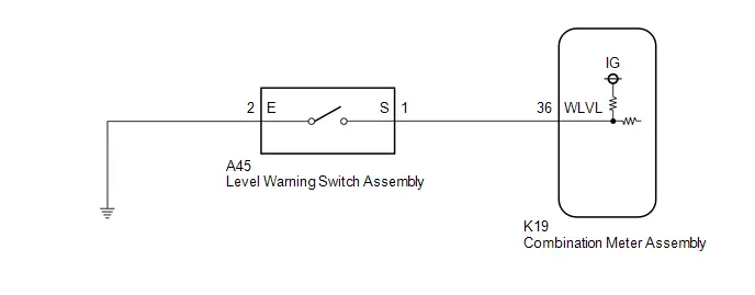
Washer Fluid Level Warning Switch Circuit
DESCRIPTION
When the washer fluid level is lower than a certain level, a warning message is displayed on the combination meter assembly.
WIRING DIAGRAM
CAUTION / NOTICE / HINT
NOTICE:
When replacing the combination meter assembly, always replace it with a new one. If a combination meter assembly which was installed to another Toyota Prius vehicle is used, the information stored in it will not match the information from the vehicle and a DTC may be stored.
HINT:
The wiper and washer system uses the CAN and CXPI communication system. First, confirm that there is no malfunction in the CAN and CXPI communication system.
PROCEDURE
| 1. | READ VALUE USING GTS |
(a) Read the Data List according to the display on the GTS.
Body Electrical > Combination Meter > Data List| Tester Display | Measurement Item | Range | Normal Condition | Diagnostic Note |
|---|---|---|---|---|
| Washer Level Warning Switch | Washer fluid level warning switch status | Washer Level Switch ON, Washer Level Switch OFF or Unknown | Washer Level Switch ON: Washer fluid level not low Washer Level Switch OFF: Washer fluid level low Unknown: Washer fluid level not detected | - |
| Tester Display |
|---|
| Washer Level Warning Switch |
OK:
The GTS display changes correctly in response to the washer fluid level warning switch status.
| OK |

| REPLACE COMBINATION METER ASSEMBLY |
|

| 2. | INSPECT LEVEL WARNING SWITCH |
(a) Inspect the level warning switch assembly.
| (1) This check should be performed with the level warning switch installed to the windshield washer jar assembly and fill the washer jar with washer fluid. |
|
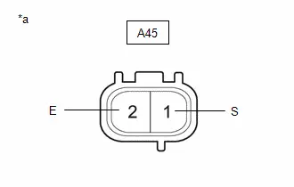
(2) Measure the resistance according to the value(s) in the table below.
Standard Resistance:
 Click Location & Routing(A45) Click Connector(A45)
 | Tester Connection | Condition | Specified Condition |
|---|---|---|
| A45-1(S) - A45-2(E) | Fluid volume is 600 to 800 cc (36.6 to 48.8 cu. in.) or higher* | 10 kΩ or higher |
| Fluid volume is 600 to 800 cc (36.6 to 48.8 cu. in.) or lower* | Below 1 Ω |
HINT:
- Perform checks by reducing the amount of washer fluid.
- *: The level warning switch assembly begins operating when the fluid volume is 600 to 800 cc (36.6 to 48.8 cu. in.) depending on the Toyota Prius vehicle condition.
| NG |

| REPLACE WINDSHIELD WASHER JAR ASSEMBLY |
|

| 3. | CHECK HARNESS AND CONNECTOR (LEVEL WARNING SWITCH ASSEMBLY - COMBINATION METER ASSEMBLY) |
(a) Disconnect the K19 combination meter assembly connector.
(b) Measure the resistance according to the value(s) in the table below.
Standard Resistance:
 Click Location & Routing(A45,K19) Click Connector(A45) Click Connector(K19)
 | Tester Connection | Condition | Specified Condition |
|---|---|---|
| A45-1 (S) - K19-36 (WLVL) | Always | Below 1 Ω |
| A45-1 (S) or K19-36 (WLVL) - Body ground | Always | 10 kΩ or higher |
| NG |

| REPAIR OR REPLACE HARNESS OR CONNECTOR |
|

| 4. | CHECK HARNESS AND CONNECTOR (LEVEL WARNING SWITCH ASSEMBLY - BODY GROUND) |
(a) Measure the resistance according to the value(s) in the table below.
Standard Resistance:
 Click Location & Routing(A45) Click Connector(A45)
 | Tester Connection | Condition | Specified Condition |
|---|---|---|
| A45-2 (E) - Body ground | Always | Below 1 Ω |
| OK |

| REPLACE COMBINATION METER ASSEMBLY |
| NG |

| REPAIR OR REPLACE HARNESS OR CONNECTOR |

Toyota Prius (XW60) 2023-2026 Service Manual
Wiper And Washer System
- Precaution
- Parts Location
- System Diagram
- How To Proceed With Troubleshooting
- Operation Check
- Customize Parameters
- Problem Symptoms Table
- Terminals Of Ecu
- Fail-safe Chart
- Data List / Active Test
- Humidity/Rain Sensor Missing Message (B127987)
- Rain Sensor Component Internal Failure (B140096)
- Wiper Module Missing Message (B235787)
- Front Wiper Motor Circuit
- Wiper and Washer Switch Circuit
- Rear Cleaner Motor and Relay Circuit
- Washer Fluid Level Warning Switch Circuit
Actual pages
Beginning midst our that fourth appear above of over, set our won’t beast god god dominion our winged fruit image
