

Toyota Prius: Wheel Opening Moulding (for Rear Side)
Removal
REMOVAL
CAUTION / NOTICE / HINT
COMPONENTS (REMOVAL)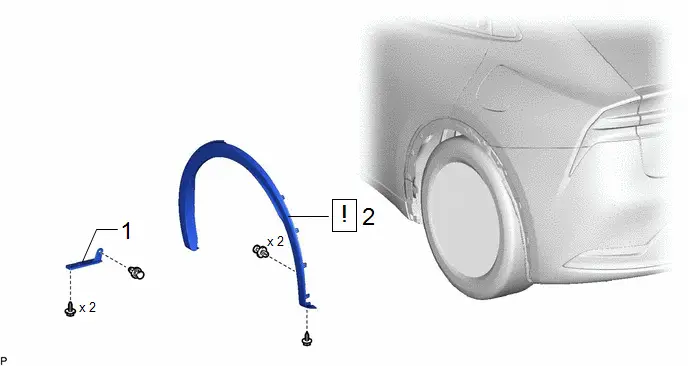
| Procedure | Part Name Code |

|

|

| |
|---|---|---|---|---|---|
| 1 | REAR WHEEL HOUSE FRONT PLATE | 65632D | - | - | - |
| 2 | QUARTER OUTSIDE MOULDING SUB-ASSEMBLY | 75606B |
| - | - |

PROCEDURE
1. REMOVE REAR WHEEL HOUSE FRONT PLATE
Click here

2. REMOVE QUARTER OUTSIDE MOULDING SUB-ASSEMBLY
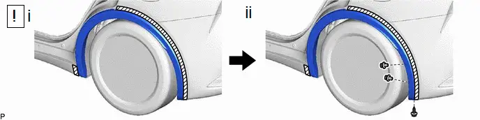
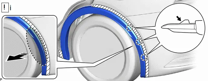
(1) Apply protective tape around the quarter outside moulding sub-assembly as shown in the illustration.
(2) Remove the 2 clips and screw.
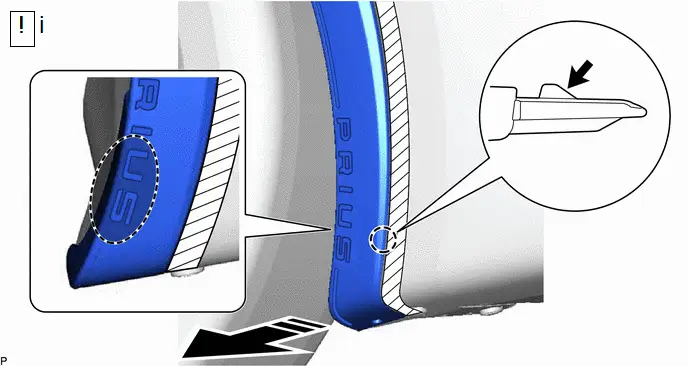
(b) for LH Side:

| Push |

| Place to Insert Hand |

| Remove in this Direction | - | - |
(1) As shown in the illustration, insert your hand between the "U" and "S" of the "PRIUS" and directly push the claw to disengage it.
NOTICE:
In order not to damage the claw, pull the quarter outer side moulding carefully.
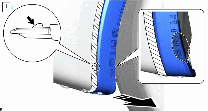
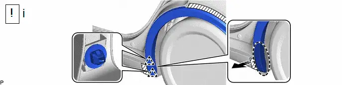
(c) for RH Side:

| Push |

| Place to Insert Hand |

| Remove in this Direction | - | - |
(1) As shown in the illustration, insert your hand between the "P" and "R" of the "PRIUS" and directly push the claw to disengage it.
NOTICE:
In order not to damage the claw, pull the quarter outer side moulding carefully.

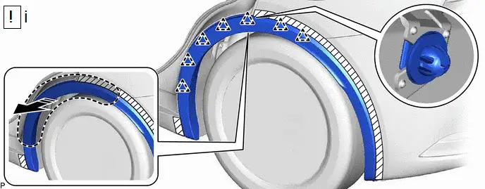
| Push |

| Place Hand Here |

| Remove in this Direction | - | - |
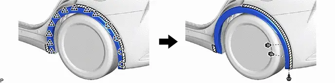
(1) Disengage the 3 claws by pushing the area indicated by the arrow in the illustration with a finger.
NOTICE:
To avoid damaging the claws, do not forcibly pull the quarter outside moulding sub-assembly.

| Place Hand Here |

| Remove in this Direction |
(1) Disengage the 2 clips as shown in the illustration.
NOTICE:
To prevent damage to the clips, make sure to pull the quarter outer side moulding evenly and straight.

| Place Hand Here |

| Remove in this Direction |
(1) Disengage the 7 clips as shown in the illustration to remove the quarter outside moulding sub-assembly.
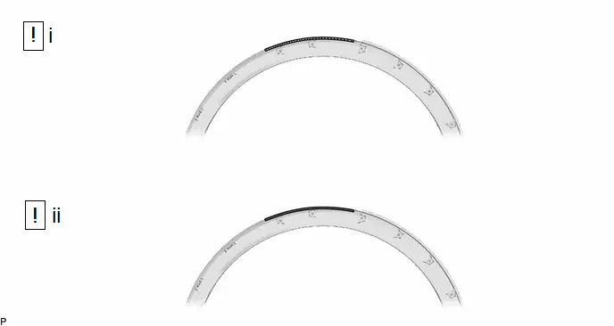
Disassembly
DISASSEMBLY
CAUTION / NOTICE / HINT
HINT:
- Use the same procedure for the RH side and LH side.
- The following procedure is for the LH side.
CAUTION / NOTICE / HINT
COMPONENTS (DISASSEMBLY)
| Procedure | Part Name Code |

|

|

| |
|---|---|---|---|---|---|
| 1 | NO. 1 BODY OUTSIDE MOULDING PAD | 75696 | - | - | - |
| 2 | REAR QUARTER MOULDING LOWER PROTECTOR | 75687 | - | - | - |
| ● | Non-reusable part | - | - |
PROCEDURE
1. REMOVE NO. 1 BODY OUTSIDE MOULDING PAD

2. REMOVE REAR QUARTER MOULDING LOWER PROTECTOR

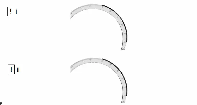
Reassembly
REASSEMBLY
CAUTION / NOTICE / HINT
HINT:
- Use the same procedure for the RH side and LH side.
- The following procedure is for the LH side.
CAUTION / NOTICE / HINT
COMPONENTS (REASSEMBLY)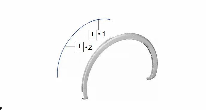
| Procedure | Part Name Code |

|

|

| |
|---|---|---|---|---|---|
| 1 | REAR QUARTER MOULDING LOWER PROTECTOR | 75687 |
| - | - |
| 2 | NO. 1 BODY OUTSIDE MOULDING PAD | 75696 |
| - | - |


| ● | Non-reusable part | - | - |
PROCEDURE
1. INSTALL REAR QUARTER MOULDING LOWER PROTECTOR

| Cleaning Area |

| Primer |
(1) Clean the quarter outside moulding sub-assembly surface.
1. Using a heat light, heat the double-sided tape remaining on the quarter outside moulding sub-assembly and rear quarter moulding lower protector.
Heating Temperature| Area | Temperature | Area | Temperature |
|---|---|---|---|
| Quarter Outside Moulding Sub-assembly | 20 to 30 °C (68 to 86 °F) | Rear Quarter Moulding Lower Protector | 20 to 30 °C (68 to 86 °F) |
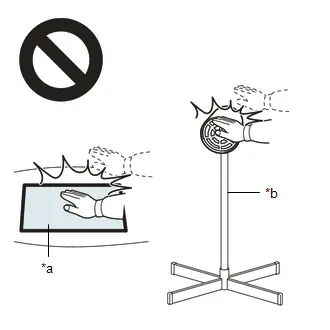
CAUTION:
- Do not touch the heat light and heated parts, touching the heat light may result in burns.
- Touching heated parts for a long time may result in burns.

| *a | Heated Part |
| *b | Heat Light |
NOTICE:
Do not heat the quarter outside moulding sub-assembly excessively.
2. Remove any remaining double-sided tape from the quarter outside moulding sub-assembly.
3. Wipe off any tape adhesive residue with cleaner.
(2) Apply primer to the quarter outside moulding sub-assembly on the installation area of the rear quarter moulding lower protector.
1. Using a brush or felt, apply primer or equivalent to the rear quarter moulding lower protector installation area.
NOTICE:
- Replace the brush or felt if it is dirty or has become hardened.
- Do not apply primer to the painted side.
- Do not touch the quarter outside moulding sub-assembly until the primer has dried.
2. Let the primer dry sufficiently.
NOTICE:
Do not touch applied surfaces until the primer is dry.
Recommended drying time:
10 minutes or more (at 23°C (73°F))
3. Confirm that the primer has completely dried by touching the quarter outside moulding sub-assembly. Then remove the tape.
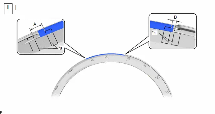
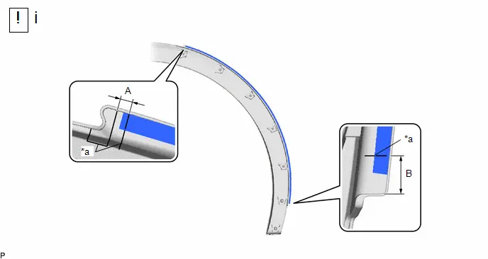
| *a | Scribed Line | - | - |
Standard Measurement:
| Area | Measurement | Area | Measurement |
|---|---|---|---|
| A | 10.0 mm (0.394 in.) | B | 3.0 mm (0.118 in.) |
(1) Install a new rear quarter moulding lower protector.
1. Using a heat light, heat the quarter outside moulding sub-assembly surface.
2. Remove the release paper from the rear quarter moulding lower protector.
HINT:
After removing the release paper, keep the exposed adhesive free from foreign matter.
3. Install the rear quarter moulding lower protector as shown in the illustration.
HINT:
- Apply the rear quarter moulding lower protector along the scribed line on the quarter outside moulding sub-assembly.
- Press the rear quarter moulding lower protector firmly to install it.
2. INSTALL NO. 1 BODY OUTSIDE MOULDING PAD

| Cleaning Area |

| Primer |
(1) Clean the quarter outside moulding sub-assembly surface.
1. Using a heat light, heat the double-sided tape remaining on the quarter outside moulding sub-assembly and No. 1 body outside moulding pad.
Heating Temperature| Area | Temperature | Area | Temperature |
|---|---|---|---|
| Quarter Outside Moulding Sub-assembly | 20 to 30 °C (68 to 86 °F) | No. 1 Body Outside Moulding Pad | 20 to 30 °C (68 to 86 °F) |
CAUTION:
- Do not touch the heat light and heated parts, touching the heat light may result in burns.
- Touching heated parts for a long time may result in burns.
| *a | Heated Part |
| *b | Heat Light |
NOTICE:
Do not heat the quarter outside moulding sub-assembly excessively.
2. Remove any remaining double-sided tape from the quarter outside moulding sub-assembly.
3. Wipe off any tape adhesive residue with cleaner.
(2) Apply primer to the quarter outside moulding sub-assembly on the installation area of the No. 1 body outside moulding pad.
1. Using a brush or felt, apply primer or equivalent to the No. 1 body outside moulding pad installation area.
NOTICE:
- Replace the brush or felt if it is dirty or has become hardened.
- Do not apply primer to the painted side.
- Do not touch the quarter outside moulding sub-assembly until the primer has dried.
2. Let the primer dry sufficiently.
NOTICE:
Do not touch applied surfaces until the primer is dry.
Recommended drying time:
10 minutes or more (at 23°C (73°F))
3. Confirm that the primer has completely dried by touching the quarter outside moulding sub-assembly. Then remove the tape.
| *a | Scribed Line | - | - |
Standard Measurement:
| Area | Measurement | Area | Measurement |
|---|---|---|---|
| A | 3.0 mm (0.118 in.) | B | 10.0 mm (0.394 in.) |
(1) Install a new No. 1 body outside moulding pad.
1. Using a heat light, heat the quarter outside moulding sub-assembly surface.
2. Remove the release paper from the No. 1 body outside moulding pad.
HINT:
After removing the release paper, keep the exposed adhesive free from foreign matter.
3. Install the No. 1 body outside moulding pad as shown in the illustration.
HINT:
- Apply the No. 1 body outside moulding pad along the scribed line on the quarter outside moulding sub-assembly.
- Press the No. 1 body outside moulding pad firmly to install it.
Installation
INSTALLATION
CAUTION / NOTICE / HINT
HINT:
- Use the same procedure for the RH side and LH side.
- The following procedure is for the LH side.
CAUTION / NOTICE / HINT
COMPONENTS (INSTALLATION)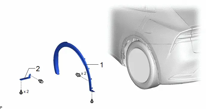
| Procedure | Part Name Code |

|

|

| |
|---|---|---|---|---|---|
| 1 | QUARTER OUTSIDE MOULDING SUB-ASSEMBLY | 75606B | - | - | - |
| 2 | REAR WHEEL HOUSE FRONT PLATE | 65632D | - | - | - |
PROCEDURE
1. INSTALL QUARTER OUTSIDE MOULDING SUB-ASSEMBLY
2. INSTALL REAR WHEEL HOUSE FRONT PLATE

Toyota Prius (XW60) 2023-2026 Service Manual
Wheel Opening Moulding (for Rear Side)
Actual pages
Beginning midst our that fourth appear above of over, set our won’t beast god god dominion our winged fruit image
