

Toyota Prius: Tire Pressure Warning Receiver
Registration
REGISTRATION
PROCEDURE
1. BEFORE REGISTRATION
NOTICE:
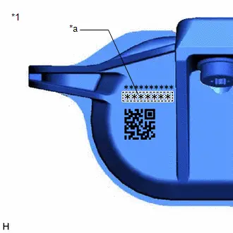
- The transmitter ID is written on the tire pressure warning valve and transmitter. It is not possible to read the transmitter ID after installing the tire onto the wheel. Therefore, make a note of the transmitter ID before installing the tire.
- Tire pressure warning ECU and receiver ID registration after replacement must be performed using the GTS.
-
Be sure to check procedures or what work is required after replacing parts.
Click here


(a) When replacing tire pressure warning ECU and receiver:
(1) Before replacing, use the GTS to read and record all of the current IDs and registered tires with transmitters (4 or 5 tires) of the tire pressure warning valve and transmitter registered to the tire pressure warning ECU and receiver.
(2) If reading the stored transmitter IDs is impossible due to malfunctions of components such as the tire pressure warning ECU and receiver, remove the tires from the wheels and check the IDs located on the tire pressure warning valve and transmitters.
(b) When replacing tire pressure warning valve and transmitter:
| (1) Take a note of the 7-digit number (transmitter ID) written on the tire pressure warning valve and transmitter. |
|
2. REGISTER TRANSMITTER ID (USING GTS)
HINT:
If the ID registration step is not completed within 300 seconds, ID registration will be canceled.
(a) Set the tire pressure to the specified value.
Click here

(b) On the GTS screen, display "ID Registration/Tire Number Registration" of Utility.
Chassis > Tire Pressure Monitor > Utility| Tester Display |
|---|
| ID Registration/Tire Number Registration |
(c) Perform the procedure displayed on the GTS.
HINT:
The number of tires with transmitters can be changed to 4 wheels only when the default value is set to 5 wheels. The number of tires is changed only when there is a special request from the customer. Normally, the default value for the number of tires is set.
3. TIRE POSITION IDENTIFICATION (USING GTS)
(a) Set the tire pressure to the specified value.
Click here

(b) On the GTS screen, display the Data List.
(c) Refer to the table below to check the tire pressure with the Data List.
Chassis > Tire Pressure Monitor > Data List| Tester Display | Measurement Item | Range | Normal Condition | Diagnostic Note |
|---|---|---|---|---|
| ID 1 Tire Inflation Pressure | ID1 tire inflation pressure | Min.: Absolute pressure (abs) / 0 kPa (0 kgf/cm2, 0 psi), Relative pressure (Gauge) / 0 kPa (0 kgf/cm2, 0 psi) Max.: Absolute pressure (abs) / 480 kPa (4.9 kgf/cm2, 70 psi), Relative pressure (Gauge) / 380 kPa (3.9 kgf/cm2, 55 psi) | Actual tire inflation pressure | Not displayed, if data has not been received.* |
| ID 2 Tire Inflation Pressure | ID2 tire inflation pressure | Min.: Absolute pressure (abs) / 0 kPa (0 kgf/cm2, 0 psi), Relative pressure (Gauge) / 0 kPa (0 kgf/cm2, 0 psi) Max.: Absolute pressure (abs) / 480 kPa (4.9 kgf/cm2, 70 psi), Relative pressure (Gauge) / 380 kPa (3.9 kgf/cm2, 55 psi) | Actual tire inflation pressure | Not displayed, if data has not been received.* |
| ID 3 Tire Inflation Pressure | ID3 tire inflation pressure | Min.: Absolute pressure (abs) / 0 kPa (0 kgf/cm2, 0 psi), Relative pressure (Gauge) / 0 kPa (0 kgf/cm2, 0 psi) Max.: Absolute pressure (abs) / 480 kPa (4.9 kgf/cm2, 70 psi), Relative pressure (Gauge) / 380 kPa (3.9 kgf/cm2, 55 psi) | Actual tire inflation pressure | Not displayed, if data has not been received.* |
| ID 4 Tire Inflation Pressure | ID4 tire inflation pressure | Min.: Absolute pressure (abs) / 0 kPa (0 kgf/cm2, 0 psi), Relative pressure (Gauge) / 0 kPa (0 kgf/cm2, 0 psi) Max.: Absolute pressure (abs) / 480 kPa (4.9 kgf/cm2, 70 psi), Relative pressure (Gauge) / 380 kPa (3.9 kgf/cm2, 55 psi) | Actual tire inflation pressure | Not displayed, if data has not been received.* |
HINT:
- *: It may take a few minutes until the values are displayed.
- The wheel position cannot be determined from ID1 through ID4 on the Data List.
| Tester Display |
|---|
| ID 1 Tire Inflation Pressure |
| ID 2 Tire Inflation Pressure |
| ID 3 Tire Inflation Pressure |
| ID 4 Tire Inflation Pressure |
(d) Rapidly reduce the tire pressure for each wheel at least 40 kPa (0.4 kgf/cm2, 5.8 psi) within 30 seconds.
NOTICE:
- It may take a few minutes until the values are displayed.
- When an "ID Tire Inflation Pressure" value has not changed, reset the tire pressure to the appropriate specified value and rotate the tire 90 to 270 degrees. Then rapidly release the tire pressure and recheck the value.
(e) Read the "ID Tire Inflation Pressure" value and identify the tire with reduced pressure, and record the corresponding tire pressure warning valve and transmitter (ID1 to ID4).
(f) Repeat for each tire.
(g) Set the tire pressure to the specified value.
Click here

(h) On the GTS screen, display "ID Registration/Tire Position Write" of Utility.
Chassis > Tire Pressure Monitor > Utility| Tester Display |
|---|
| ID Registration/Tire Position Write |
(i) Perform the procedure displayed on the GTS.
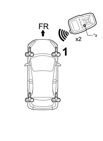
4. REGISTER TRANSMITTER ID (USING TPWS TRIGGER TOOL)
HINT:
TPWS is an abbreviation for Tire Pressure Warning System.
(a) Temporary registration:
(1) Adjust the tire pressure in all tires to the specified pressure.
Click here

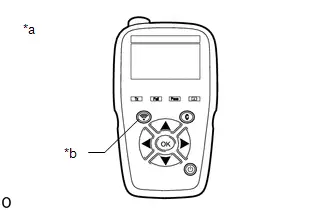
| (2) Set the TPWS trigger tool to the ID reading screen. |
|

(3) Step "A":
Turn the ignition switch to ON.
| (4) Using the steering pad switch assembly, select "Tire Set Switching" and then "Register New Valve / ID" on the multi-information display, check that the tire pressure warning light blinks, and then perform Step "B" within 35 seconds. HINT: During registration, the tire pressure warning light illuminates after blinking for 1.0 minutes and the tire pressure on the multi-information display displays "---". |
|

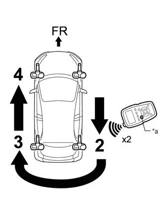
| (5) Step "B": On the TPWS trigger tool, operate the read button at the location shown in the illustration 2 times* to read and provisionally register the ID code of the tire pressure warning valve and transmitter. HINT: *: Read Button Operation -> Tire Pressure Screen Display (1 time) -> Read Button Operation -> Tire Pressure Screen Display (2 times)
NOTICE: Operate the TPWS trigger tool while facing and close to each tire pressure warning valve and transmitter. HINT:
|
|
| (6) Step "C": On the TPWS trigger tool, operate the read button at the location shown in the illustration 2 times* to read and provisionally register the ID code of the tire pressure warning valve and transmitter. HINT: *: Read Button Operation -> Tire Pressure Screen Display (1 time) -> Read Button Operation -> Tire Pressure Screen Display (2 times)
NOTICE:
HINT:
|
|
(7) Check that the tire pressure is "0" on the multi-information display.
HINT:
If the tire pressure is not "0", the temporary registration is not completed. Perform the procedure again from Step "A".
(b) Main registration and tire position registration:
| (1) Step "D": Following the sequence shown, on the TPWS trigger tool, operate the read button 1 time* at each location shown in the illustration to read and perform final registration for each tire pressure warning valve and transmitter ID and register the wheel position. HINT: *: Read Button Operation -> Tire Pressure Screen Display (1 time)
NOTICE:
HINT:
|
|

(2) Check that the tire pressure is displayed on the multi-information display.
(c) Rapidly decrease the tire pressure of each wheel to 40 kPa (0.4 kgf/cm2, 5.8 psi) or more within 30 seconds, and then check the tire pressure value on the multi-information display.
HINT:
- It may take a few minutes until the values are displayed.
- If the tire pressure data does not change, rotate the tire from 90° to 270°, and check it again.
(d) Repeat for each tire.
(e) Adjust the tire pressure in all tires to the specified pressure.
Click here

5. TIRE POSITION IDENTIFICATION (USING TPWS TRIGGER TOOL)
HINT:
TPWS is an abbreviation for Tire Pressure Warning System.
(a) Read tire pressure warning valve and transmitter ID codes and register wheel positions:
(1) Adjust the tire pressure in all tires to the specified pressure.
Click here

| (2) Set the TPWS trigger tool to the ID reading screen. |
|
(3) Turn the ignition switch to ON.
(4) Using the steering pad switch assembly, select "Tire Rotation" on the multi-information display and check that the tire pressure warning light blinks 3 times.
HINT:
During registration, the tire pressure on the multi-information display displays "---".
| (5) Step "A": Following the sequence shown, on the TPWS trigger tool, operate the read button 1 time* at each location shown in the illustration to read each tire pressure warning valve and transmitter ID and register the wheel position. HINT: *: Read Button Operation -> Tire Pressure Screen Display (1 time)
NOTICE:
HINT:
|
|
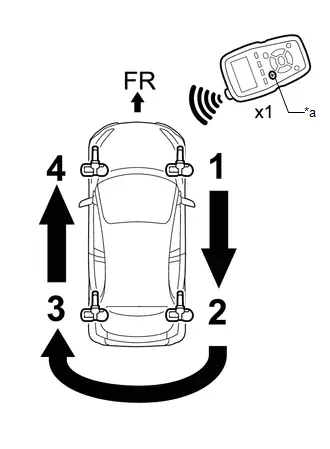
(6) Check that the tire pressure is displayed on the multi-information display.
(b) Rapidly decrease the tire pressure of each wheel to 40 kPa (0.4 kgf/cm2, 5.8 psi) or more within 30 seconds, and then check the tire pressure value on the multi-information display.
HINT:
- It may take a few minutes until the values are displayed.
- If the tire pressure data does not change, rotate the tire from 90° to 270°, and check it again.
(c) Repeat for each tire.
(d) Adjust the tire pressure in all tires to the specified pressure.
Click here

6. REGISTER TRANSMITTER ID (USING AUTOMATIC ID REGISTRATION FUNCTION)
NOTICE:
- If the transmitter IDs have not been registered, Toyota Prius Vehicle Control History (RoB) X20FA is stored in the tire pressure warning ECU and receiver after 3 minutes or more.
- If normal pressure values are displayed, the transmitter IDs have been registered correctly.
- If another tire pressure warning valve and transmitter belonging to the same system is installed to a tire other than the one transmitter registration is being performed on, automatic ID registration does not complete.
HINT:
- If the ECU Data List is displayed using the GTS while work is being performed, the registration mode will be canceled.
- Registration mode can be canceled while registration is being performed by selecting "Tire Set Switching" and then "Register New Valve / ID" on the multi-information display.
- If the ignition switch is turned off before driving during the registration procedure, registration mode will continue.
(a) Adjust the tire pressure in all tires to the specified pressure.
Click here

(b) Turn the ignition switch off and stop the Toyota Prius vehicle for 15 minutes or more.
HINT:
After stopping the vehicle for 15 minutes or more, the frequency of radio wave signals sent by the tire pressure warning valve and transmitters increases for the first few minutes of driving (8 times the normal frequency).
(c) Using the steering pad switch assembly, select "Tire Set Switching" and then "Register New Valve / ID" on the multi-information display and check that the tire pressure warning light blinks 3 times.
HINT:
During registration, the tire pressure warning light blinks for 1 minute before turning on, the multi-information display tire pressure displays as "---" and "Identify Wheel Accepted" is displayed.
(d) Drive at approximately 40 km/h (25 mph) for approximately 10 to 30 minutes during 1 trip.
(e) During the procedure, make 2 or more right or left turns.
HINT:
Do not drive the Toyota Prius vehicle in reverse during registration.
If the vehicle is driven in reverse during registration, the information may be reset before registration completes, and registration may take longer than normal to complete.
(f) When registration is completed, the tire pressure warning light turns off, the normal tire pressure is displayed on the multi-information display.
HINT:
-
Registration may take longer than normal in the following driving environments.
- Toyota Prius Vehicle is often stopped
- Vehicle is stopped for long period of time
- Vehicle is driven in reverse
- Vehicle is driven parallel to another vehicle with the same type of tire pressure warning valve and transmitter installed for a long duration of time
- Vehicle was not stopped for 15 minutes or more before registration
- Toyota Prius Vehicle was driven at 40 km/h (25 mph) or less for a long duration of time
- The ignition switch is turned from ON to off during ID registration
7. TIRE POSITION IDENTIFICATION (NOT USING GTS)
(a) Set the tire pressure to the specified value.
Click here

(b) Select "Tire rotation" on the multi-information display, then drive the Toyota Prius vehicle at 40 km/h (25 mph) or more for 10 to 30 minutes in 1 trip until each tire position is automatically identified.
HINT:
- When tire position identification is being performed, the tire pressure on the multi-information display is displayed as "---".
- Do not drive the Toyota Prius vehicle in reverse gear while performing Tire Position Identification. If the vehicle is driven in reverse gear while performing Tire Position Identification, identification information will be discarded and Tire Position Identification may take longer than usual.
-
When the vehicle is driven under the following conditions, Tire Position Identification may take longer than usual.
- The Toyota Prius vehicle is stopped frequently.
- The vehicle is stopped for a long period of time.
- The vehicle is driven in reverse gear.
- The vehicle is driven on rough roads or uneven surfaces.
8. METHOD TO SWITCH ID
NOTICE:
- If there is a malfunction in the tire pressure warning system, perform troubleshooting before switching IDs.
- To use the ID switching function, a tire and wheel set for which the IDs have already been registered is needed.
(a) Install the tire and wheel set for which the IDs have already been registered.
(b) Turn the ignition switch to ON.
| (c) Using the steering pad switch assembly, select "Tire Set Switching" and then "Register Valve / ID" on the multi-information display and check that the tire pressure warning light blinks 3 times. HINT: When the switch ID procedure is being performed, the tire pressure warning light blinks for 1 minute before turning on and the tire pressure on the multi-information display is displayed as "---". |
|
(d) Stop the Toyota Prius vehicle and wait for 2 minutes.
NOTICE:
Do not drive the vehicle during the ID switching procedure. Driving the vehicle will cause it to change to the automatic ID registration mode.
(e) When ID switching is complete, the tire pressure warning light turns off and the message "Identify Wheel Accepted" stops being displayed in the multi-information display.
(f) Perform tire position identification.
Identification using GTS: Click here

Identification by driving Toyota Prius vehicle: Click here

Identification using TPWS trigger tool: Click here

HINT:
- When wheel position identification is complete, the tire pressures are shown in the multi-information display.
- TPWS is an abbreviation for Tire Pressure Warning System.
Initialization
INITIALIZATION
NOTICE:
- Initialization can be confirmed through the tire pressure warning light.
- If the ignition switch is turned off during initialization, the tire pressure warning ECU and receiver memorizes that initialization was being performed. Therefore, it is not necessary to perform the initialization procedure again after turning the ignition switch to ON. (Only when "Setting by Current Pressure" is selected.)
- The order in which the data is received is random. (Only when "Setting by Current Pressure" is selected.)
- If the signals from all the tire pressure warning valve and transmitters are received, initialization is completed. (Only when "Setting by Current Pressure" is selected.)
-
When "Complete" is displayed for the value of Data List item "Initialization Not Completed", the initialization is completed.
Click here

- Initialization is normally completed within a few minutes. (Only when "Setting by Current Pressure" is selected.)
- If initialization has not been completed successfully, Toyota Prius Vehicle Control History (RoB) X20FE is stored after a vehicle speed of 40 km/h (25 mph) or more continues for 20 minutes or more. (Only when "Setting by Current Pressure" is selected.)
- Even if initialization is performed, the existing tire positions will not be cleared. Perform the tire position identification procedure as necessary.
BEFORE INITIALIZATION
(a) Set the tire pressure to the specified value. (Only when "Setting by Current Pressure" is selected.)
NOTICE:
Refer to the link as the procedure for adjusting the tire pressures differs depending on the temperature of the tires.
Click here

INITIALIZATION PROCEDURE
HINT:
The tire pressure warning system illuminates the tire pressure warning light to warn the driver when any of the following conditions are met:
- The tire pressure drops to approximately 75% or less of the tire pressure set when system initialization was performed using the steering pad switch assembly.
-
The tire pressure drastically decreases (approximately 20 kPa (0.2 kgf/cm2, 2.9 psi) or more within several minutes) to approximately 75% or less of the tire pressure* when the tires are warmed.
*: If initialization is performed and the Toyota Prius vehicle is driven for a certain period of time, the tire pressure set during system initialization is adjusted and set to the tire pressure when the tires are warmed from the driving conditions.
NOTICE:
If the tire pressure is decreased approximately 20 kPa (0.2 kgf/cm2, 2.9 psi) or more in order to adjust the tire pressure, even if the adjusted tire pressure is 75% or more than the tire pressure set during system initialization, the tire pressure warning light may illuminate if the tire pressure drops below 75% of the tire pressure set when the tires are warmed. In this case, perform initialization again.
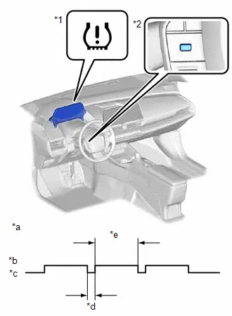
(a) Using the steering pad switch assembly, select "Tire Pressure Setting" and then "Setting by indicated air pressure" or "Setting by Current Pressure" on the multi-information display and check that the tire pressure warning light blinks 3 times.
| *1 | Tire Pressure Warning Light |
| *2 | "OK" Switch (Steering Pad Switch Assembly) |
| *a | Tire Pressure Warning Light Output Pattern |
| *b | 1 sec. |
| *c | ON |
| *d | OFF |
(b) Display the Data List items shown in the following table.
Chassis > Tire Pressure Monitor > Data List| Tester Display | Measurement Item | Range | Normal Condition | Diagnostic Note |
|---|---|---|---|---|
| ID 1 Tire Inflation Pressure | ID1 tire inflation pressure | Min.: Absolute pressure (abs) / 0 kPa (0 kgf/cm2, 0 psi), Relative pressure (Gauge) / 0 kPa (0 kgf/cm2, 0 psi) Max.: Absolute pressure (abs) / 480 kPa (4.9 kgf/cm2, 70 psi), Relative pressure (Gauge) / 380 kPa (3.9 kgf/cm2, 55 psi) | Actual tire inflation pressure | Not displayed, if data has not been received.* |
| ID 2 Tire Inflation Pressure | ID2 tire inflation pressure | Min.: Absolute pressure (abs) / 0 kPa (0 kgf/cm2, 0 psi), Relative pressure (Gauge) / 0 kPa (0 kgf/cm2, 0 psi) Max.: Absolute pressure (abs) / 480 kPa (4.9 kgf/cm2, 70 psi), Relative pressure (Gauge) / 380 kPa (3.9 kgf/cm2, 55 psi) | Actual tire inflation pressure | Not displayed, if data has not been received.* |
| ID 3 Tire Inflation Pressure | ID3 tire inflation pressure | Min.: Absolute pressure (abs) / 0 kPa (0 kgf/cm2, 0 psi), Relative pressure (Gauge) / 0 kPa (0 kgf/cm2, 0 psi) Max.: Absolute pressure (abs) / 480 kPa (4.9 kgf/cm2, 70 psi), Relative pressure (Gauge) / 380 kPa (3.9 kgf/cm2, 55 psi) | Actual tire inflation pressure | Not displayed, if data has not been received.* |
| ID 4 Tire Inflation Pressure | ID4 tire inflation pressure | Min.: Absolute pressure (abs) / 0 kPa (0 kgf/cm2, 0 psi), Relative pressure (Gauge) / 0 kPa (0 kgf/cm2, 0 psi) Max.: Absolute pressure (abs) / 480 kPa (4.9 kgf/cm2, 70 psi), Relative pressure (Gauge) / 380 kPa (3.9 kgf/cm2, 55 psi) | Actual tire inflation pressure | Not displayed, if data has not been received.* |
HINT:
- *: It may take a few minutes until the values are displayed.
- The wheel position cannot be determined from ID1 through ID4 on the Data List.
| Tester Display |
|---|
| ID 1 Tire Inflation Pressure |
| ID 2 Tire Inflation Pressure |
| ID 3 Tire Inflation Pressure |
| ID 4 Tire Inflation Pressure |
(c) Check that initialization has been completed.
(d) When the value of Data List item "Initialization Not Completed" is "Complete", the initialization is completed.
Chassis > Tire Pressure Monitor > Data List| Tester Display | Measurement Item | Range |
|---|---|---|
| Initialization Not Completed | Initialization incomplete | Complete / Not Complete |
| Tester Display |
|---|
| Initialization Not Completed |
Removal
REMOVAL
CAUTION / NOTICE / HINT
The necessary procedures (adjustment, calibration, initialization or registration) that must be performed after parts are removed and installed, or replaced during tire pressure warning ECU and receiver removal/installation are shown below.
Necessary Procedures After Parts Removed/Installed/Replaced| Replaced Part or Performed Procedure | Necessary Procedure | Effect/Inoperative Function when Necessary Procedure not Performed | Link |
|---|---|---|---|
| Tire pressure warning ECU and receiver |
| Tire Pressure Warning System | Refer to Procedures Necessary When Replacing Parts (for Tire Pressure Warning System)
|

CAUTION / NOTICE / HINT
w/ Rear Seat Side Airbag:CAUTION:
Be sure to read Precaution thoroughly before servicing.
Click here

CAUTION / NOTICE / HINT
NOTICE:
-
When replacing the tire pressure warning ECU and receiver, read the transmitter IDs stored in the old ECU using the GTS and write them down before removal.
Click here

- After the ignition switch is turned off, the radio and display receiver assembly records various types of memory and settings. As a result, after turning the ignition switch off, make sure to wait at least 3 minutes before disconnecting the cable from the negative (-) auxiliary battery terminal.
- When the cable is disconnected from the negative (-) auxiliary battery terminal and the security lock setting has been enabled, multi-display operations will be disabled upon next startup unless the password is entered. Be sure to check the security lock setting before disconnecting the cable from the negative (-) auxiliary battery terminal.
CAUTION / NOTICE / HINT
HINT:
When the cable is disconnected / reconnected to the auxiliary battery terminal, systems temporarily stop operating. However, each system has a function that completes learning the first time the system is used.
Learning completes when Toyota Prius vehicle is driven| Effect/Inoperative Function when Necessary Procedure not Performed | Necessary Procedure | Link |
|---|---|---|
| Front Camera System | Drive the Toyota Prius vehicle straight ahead at 35 km/h (22 mph) or more for 5 seconds or more. |
|

| Effect/Inoperative Function when Necessary Procedure not Performed | Necessary Procedure | Link |
|---|---|---|
|
*1: w/o Power Back Door System
*2: w/ Power Back Door System | ||
| Power Door Lock Control System*1
| Perform door unlock operation with door control switch or electrical key transmitter sub-assembly switch. |
|
| Power Back Door System*2 | Reset back door close position |
|
| Air Conditioning System | for HEV Model:
for PHEV Model:
| - |


CAUTION / NOTICE / HINT
COMPONENTS (REMOVAL)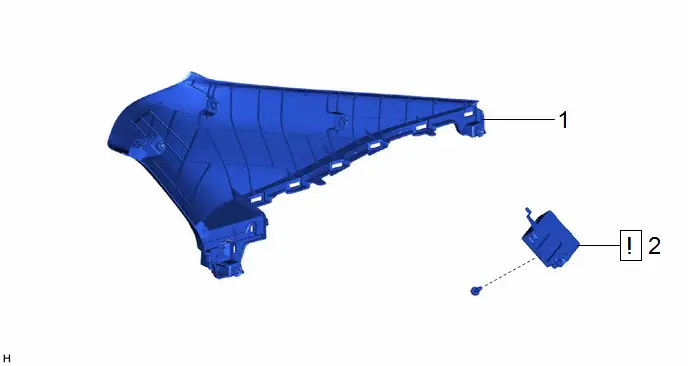
CAUTION / NOTICE / HINT
| Procedure | Part Name Code |

|

|

| |
|---|---|---|---|---|---|
| 1 | ROOF SIDE INNER GARNISH ASSEMBLY LH | 62480A | - | - | - |
| 2 | TIRE PRESSURE WARNING ECU AND RECEIVER | 897B0A |
| - | - |

PROCEDURE
1. REMOVE ROOF SIDE INNER GARNISH ASSEMBLY LH
Click here

2. REMOVE TIRE PRESSURE WARNING ECU AND RECEIVER

| NOTICE:
|

Installation
INSTALLATION
CAUTION / NOTICE / HINT
COMPONENTS (INSTALLATION)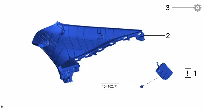
| Procedure | Part Name Code |

|

|

| |
|---|---|---|---|---|---|
| 1 | TIRE PRESSURE WARNING ECU AND RECEIVER | 897B0A |
| - | - |
| 2 | ROOF SIDE INNER GARNISH ASSEMBLY LH | 62480A | - | - | - |
| 3 | PERFORM INITIALIZATION | - | - | - |
|


| N*m (kgf*cm, ft.*lbf): Specified torque | - | - |
PROCEDURE
1. INSTALL TIRE PRESSURE WARNING ECU AND RECEIVER

| NOTICE:
|
Torque:
10 N·m {102 kgf·cm, 7 ft·lbf}
2. INSTALL ROOF SIDE INNER GARNISH ASSEMBLY LH
Click here


3. PERFORM INITIALIZATION
Click here


HINT:
Refer to Procedures Necessary When Replacing Parts (for Tire Pressure Warning System).

Toyota Prius (XW60) 2023-2026 Service Manual
Tire Pressure Warning Receiver
Actual pages
Beginning midst our that fourth appear above of over, set our won’t beast god god dominion our winged fruit image
