

Toyota Prius: Throttle Body
On-vehicle Inspection
ON-VEHICLE INSPECTION
PROCEDURE
1. INSPECT THROTTLE BODY ASSEMBLY
(a) Before cleaning, or after cleaning the throttle body with motor assembly and installing it to the vehicle, turn the ignition switch to ON without operating the accelerator pedal sensor assembly.
NOTICE:
If the accelerator pedal sensor assembly has been operated, restart the procedure from the step above.
(b) Connect the GTS to the DLC3 and check for DTCs. If DTCs are stored, repair them by following the repair procedure flow. If DTCs are not stored, perform the throttle body operation check.
(c) Check throttle body operation.
(1) Enter the following menus:
Powertrain / Engine / Active Test / Control the ETCS Open/Close Slow Speed
(2) During Active Test operation, check the Data List items "Throttle Position Command" and "Throttle Position Sensor No.1 Voltage".
Powertrain > Engine > Active Test| Active Test Display |
|---|
| Control the ETCS Open/Close Slow Speed |
| Data List Display |
|---|
| Throttle Position Sensor No.1 Voltage |
| Throttle Position Command |
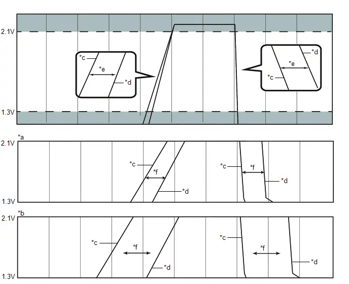
| *a | Correct | *b | Incorrect |
| *c | Throttle Position Command | *d | Throttle Position Sensor No.1 Voltage |
| *e | Specified Condition | *f | 200 ms |
OK:
| Tester Display | Condition | Specified Condition |
|---|---|---|
| Throttle Position Command Throttle Position Sensor No.1 Voltage | Checked during Active Test operation at a voltage of 1.3 V to 2.1 V. | Response lag between Throttle Position Command and Throttle Position Sensor No.1 Voltage is within 200 ms. |
(3) Enter the following menus:
Powertrain / Engine / Active Test / Control the ETCS Open/Close Fast Speed
(4) During Active Test operation, check the Data List items "Throttle Position Command" and "Throttle Position Sensor No.1 Voltage".
Powertrain > Engine > Active Test| Active Test Display |
|---|
| Control the ETCS Open/Close Fast Speed |
| Data List Display |
|---|
| Throttle Position Sensor No.1 Voltage |
| Throttle Position Command |
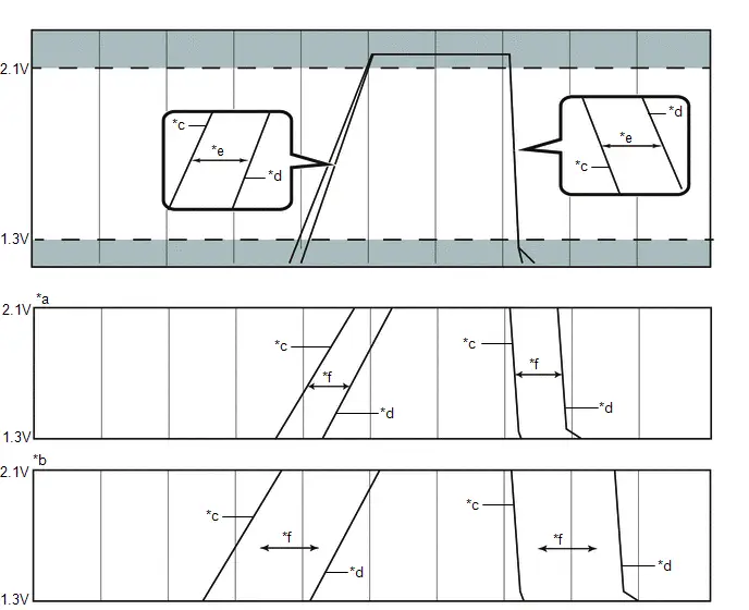
| *a | Correct | *b | Incorrect |
| *c | Throttle Position Command | *d | Throttle Position Sensor No.1 Voltage |
| *e | Specified Condition | *f | 200 ms |
OK:
| Tester Display | Condition | Specified Condition |
|---|---|---|
| Throttle Position Command Throttle Position Sensor No.1 Voltage | Checked during Active Test operation at a voltage of 1.3 V to 2.1 V. | Response lag between Throttle Position Command and Throttle Position Sensor No.1 Voltage is within 200 ms. |
(d) If there was any abnormality found during the throttle body operation check, clean the throttle body, then reassemble it and perform the throttle body operation check again. If the operation returns to normal, the procedure is complete. If operation does not return to normal, replace the throttle body assembly.
(e) Perform "Inspection After Repair" after replacing or cleaning the throttle body assembly.
HINT:
Click here

Removal
REMOVAL
CAUTION / NOTICE / HINT
The necessary procedures (adjustment, calibration, initialization or registration) that must be performed after parts are removed and installed, or replaced during throttle body assembly removal/installation are shown below.
Necessary Procedures After Parts Removed/Installed/Replaced| Replaced Part or Performed Procedure | Necessary Procedure | Effect/Inoperative Function when Necessary Procedure not Performed | Link |
|---|---|---|---|
| Inspection after repair |
|
|

CAUTION / NOTICE / HINT
COMPONENTS (REMOVAL)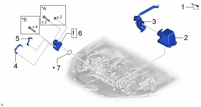
| Procedure | Part Name Code |

|

|

| |
|---|---|---|---|---|---|
| 1 | DRAIN ENGINE COOLANT (for Engine) | - | - |
| - |
| 2 | AIR CLEANER CAP SUB-ASSEMBLY | 17705 | - | - | - |
| 3 | AIR CLEANER HOSE ASSEMBLY | - | - | - | - |
| 4 | WATER BY-PASS HOSE | 16261 | - | - | - |
| 5 | NO. 2 WATER BY-PASS HOSE | 16264 | - | - | - |
| 6 | THROTTLE BODY ASSEMBLY | 22210 |
| - | - |
| 7 | THROTTLE BODY GASKET | 22271 | - | - | - |


| *A | w/ Stud Bolt | *B | w/o Stud Bolt |
| ● | Non-reusable part | - | - |
PROCEDURE
1. DRAIN ENGINE COOLANT (for Engine)
Click here

2. REMOVE AIR CLEANER CAP SUB-ASSEMBLY
3. REMOVE AIR CLEANER HOSE ASSEMBLY

4. DISCONNECT WATER BY-PASS HOSE

5. DISCONNECT NO. 2 WATER BY-PASS HOSE

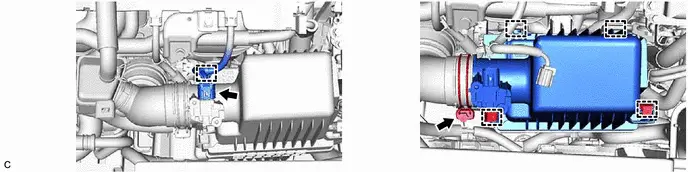
6. REMOVE THROTTLE BODY ASSEMBLY

| NOTICE: If the throttle body assembly has been struck or dropped, replace it. |
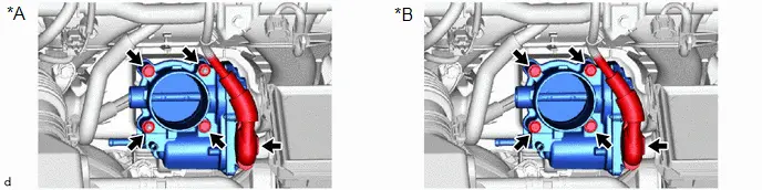
| *A | w/ Stud Bolt | *B | w/o Stud Bolt |
7. REMOVE THROTTLE BODY GASKET

Inspection
INSPECTION
PROCEDURE
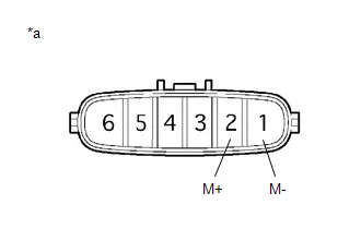
1. INSPECT THROTTLE BODY ASSEMBLY
| (a) Measure the resistance according to the value(s) in the table below. Standard Resistance:
If the result is not as specified, replace the throttle body assembly. |
|
Installation
INSTALLATION
CAUTION / NOTICE / HINT
COMPONENTS (INSTALLATION)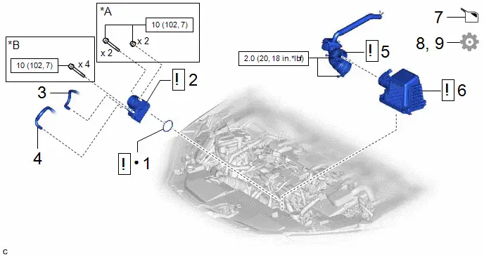
| Procedure | Part Name Code |

|

|

| |
|---|---|---|---|---|---|
| 1 | THROTTLE BODY GASKET | 22271 |
| - | - |
| 2 | THROTTLE BODY ASSEMBLY | 22210 |
| - | - |
| 3 | NO. 2 WATER BY-PASS HOSE | 16264 | - | - | - |
| 4 | WATER BY-PASS HOSE | 16261 | - | - | - |
| 5 | AIR CLEANER HOSE ASSEMBLY | - |
| - | - |
| 6 | AIR CLEANER CAP SUB-ASSEMBLY | 17705 |
| - | - |
| 7 | ADD ENGINE COOLANT (for Engine) | - | - |
| - |
| 8 | INSPECT FOR COOLANT LEAK (for Engine) | - | - | - |
|
| 9 | PERFORM INITIALIZATION | - | - | - |
|


| *A | w/ Stud Bolt | *B | w/o Stud Bolt |

| N*m (kgf*cm, ft.*lbf): Specified torque | ● | Non-reusable part |
PROCEDURE
1. INSTALL THROTTLE BODY GASKET

| *a | Protrusion | *b | Gutter |
(1) Install a new throttle body gasket to the intake manifold with the protrusion of the throttle body gasket oriented as shown in the illustration.
2. INSTALL THROTTLE BODY ASSEMBLY

| NOTICE: If the throttle body assembly has been struck or dropped, replace it. |
Torque:
10 N·m {102 kgf·cm, 7 ft·lbf}
3. CONNECT NO. 2 WATER BY-PASS HOSE
4. CONNECT WATER BY-PASS HOSE
5. INSTALL AIR CLEANER HOSE ASSEMBLY
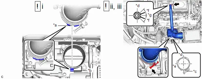
| *a | Cutout | *b | Protrusion |
| *c | Stopper | *d | Top |
| *e | Right of Toyota Prius Vehicle | *f | 45° |
| *g | Left of Vehicle | - | - |
(1) Install the air cleaner hose assembly to the throttle body assembly.
NOTICE:
Align the cutout of the air cleaner hose assembly with the protrusion of the throttle body assembly.
(2) Tighten the hose clamp in the position shown in the illustration.
Torque:
2.0 N·m {20 kgf·cm, 18 in·lbf}
(3) Connect the No. 2 ventilation hose to the cylinder head cover sub-assembly and slide the clip to secure it.
NOTICE:
Make sure that the clip is in the correct position.
6. INSTALL AIR CLEANER CAP SUB-ASSEMBLY

| *a | Cutout | *b | Protrusion |
| *c | Stopper | *d | Top |
| *e | Front of Toyota Prius Vehicle | - | - |
(1) Install the air cleaner cap sub-assembly to the air cleaner hose assembly.
NOTICE:
Align the cutout of the air cleaner hose assembly with the protrusion of the air cleaner cap sub-assembly.
(2) Tighten the hose clamp in the position shown in the illustration.
Torque:
2.0 N·m {20 kgf·cm, 18 in·lbf}
HINT:
Make sure that the hose clamp is positioned as shown in the illustration.
(3) Engage the 2 guides and install the air cleaner cap sub-assembly to the air cleaner case sub-assembly.
(4) Engage the 2 clamps.
(5) Connect the wire harness clamp.
(6) Connect the mass air flow meter connector.
7. ADD ENGINE COOLANT (for Engine)
Click here

8. INSPECT FOR COOLANT LEAK (for Engine)
Click here

9. PERFORM INITIALIZATION
Click here


Toyota Prius (XW60) 2023-2026 Service Manual
Throttle Body
Actual pages
Beginning midst our that fourth appear above of over, set our won’t beast god god dominion our winged fruit image
