

Toyota Prius: Sfi System
- Precaution
- Definition Of Terms
- Parts Location
- System Diagram
- How To Proceed With Troubleshooting
- Check For Intermittent Problems
- Basic Inspection
- Registration
- Initialization
- Terminals Of Ecm
- Diagnosis System
- Dtc Check / Clear
- Freeze Frame Data
- Check Mode Procedure
- Fail-safe Chart
- Data List / Active Test
- Vehicle Control History
- A Camshaft Position Actuator Bank 1 Circuit Open (P001013)
- Camshaft Position "A" - Timing Over-Advanced or System Performance Bank 1 (P001100,P001200)
- Crankshaft Position - Camshaft Position Correlation Bank 1 Sensor A (P001600)
- HO2S Heater Control Bank 1 Sensor 1 Circuit Short to Battery (P003012,P003013,P101A9E)
- HO2S Heater Control Circuit Bank 1 Sensor 2 Circuit Short to Battery (P003612,P003614,P102A9E)
- Manifold Absolute Pressure - Barometric Pressure Correlation (P006900)
- Mass or Volume Air Flow Sensor "A" Circuit Short to Battery (P010012,P010014)
- Manifold Absolute Pressure / Barometric Pressure Sensor Circuit Short to Ground (P010511)
- Manifold Absolute Pressure / Barometric Pressure Sensor Circuit Short to Battery or Open (P010515)
- Intake Air Temperature Sensor 1 Bank 1 Circuit Short to Ground (P011011)
- Intake Air Temperature Sensor 1 Bank 1 Circuit Short to Battery or Open (P011015)
- Engine Coolant Temperature Sensor 1 Circuit Short to Ground (P011511)
- Engine Coolant Temperature Sensor 1 Circuit Short to Battery or Open (P011515)
- Engine Coolant Temperature Sensor 1 Signal Stuck in Range (P01152A)
- Throttle / Pedal Position Sensor / Switch "A" Circuit Short to Ground (P012011)
- Throttle / Pedal Position Sensor / Switch "A" Circuit Short to Battery or Open (P012015)
- Throttle / Pedal Position Sensor / Switch "A" Circuit Voltage Out of Range (P01201C)
- O2 Sensor Circuit Bank 1 Sensor 2 Circuit Open (P013613,P013617,P01361C)
- System Too Lean Bank 1 (P017100,P017200)
- Throttle/Pedal Position Sensor/Switch "B" Circuit Short to Ground (P022011)
- Throttle/Pedal Position Sensor/Switch "B" Circuit Short to Battery or Open (P022015)
- Random/Multiple Cylinder Misfire Detected (P030000,P030027,P030085-P030400)
- Knock Sensor 1 Bank 1 or Single Sensor Circuit Short to Ground (P032511)
- Knock Sensor 1 Bank 1 or Single Sensor Circuit Short to Battery or Open (P032515)
- Crankshaft Position Sensor "A" Circuit Short to Ground (P033511)
- Crankshaft Position Sensor "A" Circuit Short to Battery or Open (P033515)
- Crankshaft Position Sensor "A" Signal Stuck in Range (P03352A)
- Crankshaft Position Sensor "A" No Signal (P033531)
- Camshaft Position Sensor "A" Bank 1 or Single Sensor Circuit Short to Ground (P034011)
- Camshaft Position Sensor "A" Bank 1 or Single Sensor Circuit Short to Battery or Open (P034015)
- Camshaft Position Sensor "A" Bank 1 or Single Sensor Signal Stuck in Range (P03402A)
- Camshaft Position Sensor "A" Bank 1 or Single Sensor No Signal (P034031)
- Exhaust Gas Recirculation "A" Low / Insufficient Flow (P04019C)
- Exhaust Gas Recirculation "A" Control Circuit 1 Open (P040314,P140000,P140596,P141004)
- Catalyst System Efficiency Below Threshold Bank 1 (P042000)
- Evaporative Emission System Purge Control Valve "A" Circuit Open (P044313)
- System Voltage Circuit Short to Ground or Open (P056014)
- Internal Control Module Random Access Memory (RAM) Error Data Memory Failure (P060444)
- Control Module Processor Watchdog/Safety MCU Failure (P060647)
- Control Module Performance Bank 1 Watchdog/Safety MCU Failure (P060747,P060787)
- Internal Control Module Throttle Position Performance Internal Electronic Failure (P060E49)
- VIN Not Programmed (P063051)
- Actuator Supply Voltage "A" Circuit Short to Ground or Open (P065714)
- Throttle Actuator "A" Control Motor Circuit Current Below Threshold (P210018,P210019)
- Throttle/Pedal Position Sensor "A" Minimum Stop Performance (P210900)
- Throttle Actuator "A" Control System Actuator Stuck Open (P211172,P211173)
- Throttle Actuator "A" Control Throttle Body Range/Performance (P211900,P211904,P211977,P21199B)
- Throttle/Pedal Position Sensor/Switch "A"/"B" Voltage Correlation Signal Cross Coupled (P21352B)
- A/F (O2) Sensor Signal Biased/Stuck Lean Bank 1 Sensor 1 Circuit Current Above Threshold (P219519,P219524,P219618,P219623)
- Barometric Pressure Sensor "A" Circuit Short to Ground (P222611,P222615)
- Barometric Pressure Sensor "A" Missing Message (P222687,P222696)
- A/F (O2) Sensor Positive Current Control Circuit / Open Bank 1 Sensor 1 (P223700,P223711,P223712,P223713,P22371B,P225111,P225112)
- Ignition Switch On/Start Position Circuit Low Circuit Short to Ground or Open (P253314)
- ECM/PCM Engine Off Timer Performance Signal Invalid (P261029)
- Engine Coolant Pump Circuit Short to Battery (P26CA12)
- Engine Coolant Pump No Signal (P26CA31)
- Engine Coolant Pump Actuator Stuck (P26CB71)
- Engine Coolant Pump Overspeed (P26CE37)
- O2 Sensor Circuit Range/Performance Bank 1 Sensor 1 Signal Rate of Change Below Threshold (P2A0026)
- Poor Engine Power (P319000,P319100)
- Fuel Run Out (P319300)
- Lost Communication with Drive Motor Control Module "A" Missing Message (U011087)
- Lost Communication with Hybrid/EV Battery Energy Control Module "A" Missing Message (U011187)
- Lost Communication With Hybrid Powertrain Control Module Missing Message (U029387)
- Lost Communication with Hybrid Powertrain Control Module (ch2) Missing Message (U115087)
- ECM Power Source Circuit
- VC Output Circuit
- Fuel Pump Control Circuit
- Fuel Injector Circuit
- MIL Circuit
- Ignition Circuit
- Rough Idling
Precaution
PRECAUTION
WHEN USING GTS
CAUTION:
Observe the following items for safety reasons:
- Before using the GTS, read the instruction manual.
- Prevent the GTS cable from being caught on the pedals, shift lever or steering wheel when driving with the GTS connected to the Toyota Prius vehicle.
- When driving the vehicle for testing purposes using the GTS, 2 persons are required. One to drive the vehicle, and another to operate the GTS.
INITIALIZATION
NOTICE:
-
Perform Registration (VIN registration or frame number registration) when replacing the ECM.
Click here

-
When the ECM is replaced, update the ECU security key.
Click here

-
Perform Learning Value Reset and Idle Learning after replacing or servicing parts related to engine operation.
Click here

PRECAUTIONS FOR DISCONNECTING CABLE FROM NEGATIVE (-) AUXILIARY BATTERY TERMINAL
NOTICE:
-
After the ignition switch is turned off, there may be a waiting time before disconnecting the negative (-) auxiliary battery terminal.
Click here

-
When disconnecting and reconnecting the auxiliary battery.
HINT:
When disconnecting and reconnecting the auxiliary battery, there is an automatic learning function that completes learning when the respective system is used.
Click here


PRECAUTIONS FOR INSPECTING HYBRID CONTROL SYSTEM
(a) Refer to Hybrid Control System.
Click here

NOTICE FOR HYBRID CONTROL SYSTEM ACTIVATION
(a) Refer to Hybrid Control System.
Click here

Definition Of Terms
DEFINITION OF TERMS
| Term | Definition |
|---|---|
| Monitor Description | Description of what the ECM monitors and how it detects malfunctions (monitoring purpose and details). |
| Typical Enabling Conditions | Preconditions that allow the ECM to detect malfunctions. With all preconditions satisfied, the ECM stores a DTC when the monitored value(s) exceeds the malfunction threshold(s). |
| Required Sensors/Components | The sensors and components that are used by the ECM to detect malfunctions. |
| Frequency of Operation | The number of times that the ECM checks for malfunctions per driving cycle. "Once per driving cycle" means that the ECM detects a malfunction only once during a single driving cycle. "Continuous" means that the ECM detects a malfunction every time the enabling conditions are met. |
| Duration | The minimum time for which the ECM must detect a continuous deviation in the monitored value(s) in order to store a DTC. Timing begins after the "typical enabling conditions" are met. |
| Typical Malfunction Thresholds | Value beyond which the ECM will determine that there is a malfunction and stores a DTC. |
Parts Location
PARTS LOCATION
ILLUSTRATION
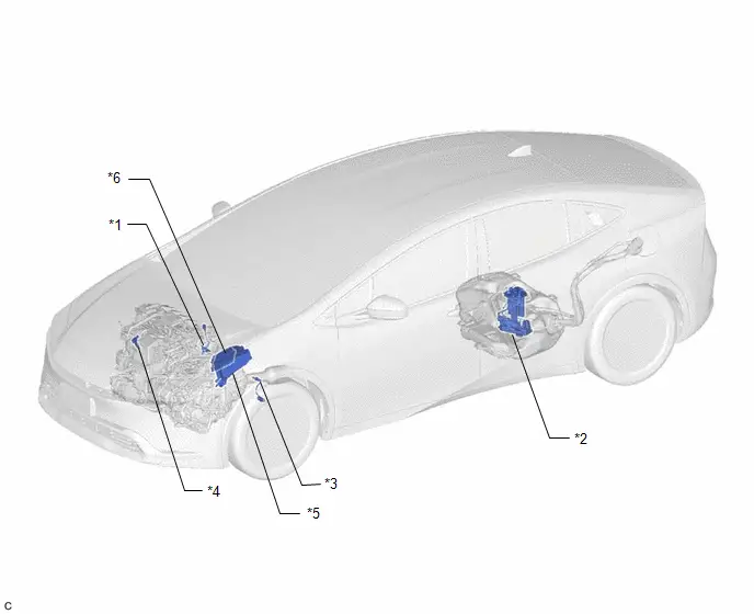
| *1 | AIR FUEL RATIO SENSOR | *2 | FUEL PUMP |
| *3 | HEATED OXYGEN SENSOR | *4 | MASS AIR FLOW METER SUB-ASSEMBLY |
| *5 | NO. 1 ENGINE ROOM RELAY BLOCK AND NO. 1 JUNCTION BLOCK ASSEMBLY | *6 | ECM |
ILLUSTRATION
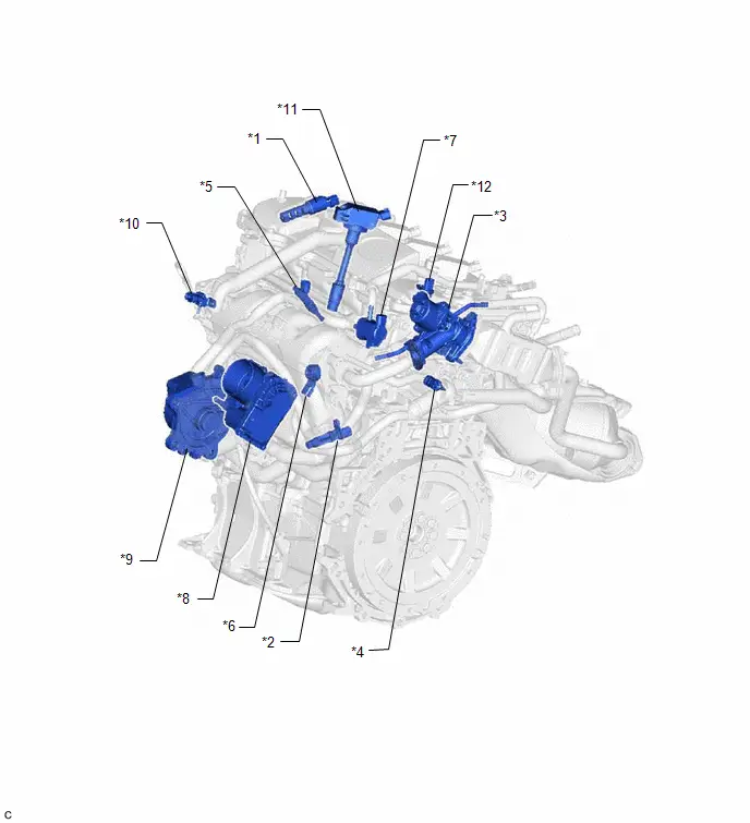
| *1 | CAMSHAFT TIMING OIL CONTROL VALVE ASSEMBLY | *2 | CRANKSHAFT POSITION SENSOR |
| *3 | EGR VALVE ASSEMBLY | *4 | ENGINE COOLANT TEMPERATURE SENSOR |
| *5 | FUEL INJECTOR ASSEMBLY | *6 | KNOCK CONTROL SENSOR |
| *7 | PURGE VSV | *8 | THROTTLE BODY ASSEMBLY |
| *9 | ENGINE WATER PUMP ASSEMBLY | *10 | MANIFOLD ABSOLUTE PRESSURE SENSOR |
| *11 | IGNITION COIL ASSEMBLY | *12 | CAMSHAFT POSITION SENSOR |
ILLUSTRATION
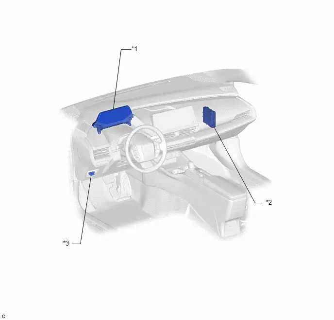
| *1 | COMBINATION METER ASSEMBLY | *2 | HYBRID Toyota Prius Vehicle CONTROL ECU |
| *3 | DLC3 | - | - |
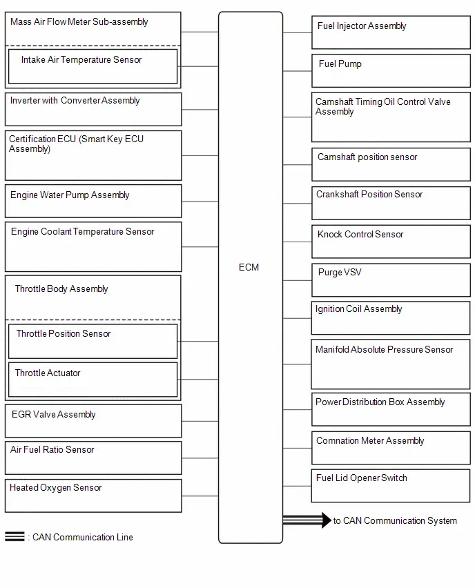
System Diagram
SYSTEM DIAGRAM
How To Proceed With Troubleshooting
CAUTION / NOTICE / HINT
HINT:
*: Use the GTS.
PROCEDURE
| 1. | VEHICLE BROUGHT TO WORKSHOP |
|

| 2. | CUSTOMER PROBLEM ANALYSIS |
|

| 3. | CONNECT GTS TO DLC3* |
HINT:
If the display indicates a communication malfunction, inspect the DLC3.
When any CAN communication system DTCs are output, perform troubleshooting for the CAN communication system first.
|

| 4. | CHECK DTC AND FREEZE FRAME DATA* |
(a) Check for DTCs.
Powertrain > Engine > Trouble Codes(b) Check for freeze frame data.
Click here

HINT:
Record or print DTCs and freeze frame data if necessary.
|

| 5. | CLEAR DTC AND FREEZE FRAME DATA* |
(a) Clear the DTCs and freeze frame data.
Powertrain > Engine > Clear DTCs
|

| 6. | CONDUCT VISUAL INSPECTION |
|

| 7. | SELECT CHECK MODE DIAGNOSIS* |
(a) Change the ECM from normal mode to check mode.
Click here

| Tester Display |
|---|
| Check Mode |
|

| 8. | CONFIRM PROBLEM SYMPTOMS |
(a) Confirm the problem symptoms.
HINT:
If the engine does not start, first perform the "Check DTC" procedure and "Conduct Basic Inspection" procedure below.
| Result | Proceed to |
|---|---|
| Malfunction does not occur | A |
| Malfunction occurs | B |
| B |

| GO TO STEP 10 |
|

| 9. | SIMULATE SYMPTOMS |
HINT:
Refer to Symptom Simulation.
Click here

|

| 10. | CHECK DTC* |
(a) Check for DTCs.
Powertrain > Engine > Trouble Codes| Result | Proceed to |
|---|---|
| DTCs are output | A |
| DTCs are not output | B |
| B |

| GO TO STEP 12 |
|

| 11. | REFER TO DTC CHART |
HINT:
Refer to Diagnostic Trouble Code Chart.
Click here

|

| 12. | CONDUCT BASIC INSPECTION |
(a) Conduct basic inspection.
Click here

| Result | Proceed to |
|---|---|
| Malfunctioning parts not confirmed | A |
| Malfunctioning parts confirmed | B |
| B |

| GO TO STEP 17 |
|

| 13. | REFER TO PROBLEM SYMPTOMS TABLE |
HINT:
Refer to Problem Symptoms Table.
Click here

| Result | Proceed to |
|---|---|
| Malfunctioning circuit confirmed | A |
| Malfunctioning parts confirmed | B |
| B |

| GO TO STEP 17 |
|

| 14. | CHECK ECM POWER SOURCE CIRCUIT |
(a) Check the ECM power source circuit.
Click here

|

| 15. | CONDUCT CIRCUIT INSPECTION |
| Result | Proceed to |
|---|---|
| Malfunction not confirmed | A |
| Malfunction confirmed | B |
| B |

| GO TO STEP 18 |
|

| 16. | CHECK FOR INTERMITTENT PROBLEMS |
(a) Check for intermittent problems.
Click here

|

| 17. | CONDUCT PARTS INSPECTION |
|

| 18. | IDENTIFY PROBLEM |
|

| 19. | ADJUST AND/OR REPAIR |
|

| 20. | CONDUCT CONFIRMATION TEST |
| NEXT |

| END |
Check For Intermittent Problems
CHECK FOR INTERMITTENT PROBLEMS
HINT:
Inspect the vehicle ECM using check mode. Intermittent problems are easier to detect with the GTS when the ECM is in check mode. In check mode, the ECM uses 1 trip detection logic, which is more sensitive to malfunctions than normal mode (default), which uses 2 trip detection logic.
-
Clear the DTCs.
Click here

-
Change the ECM from normal mode to check mode using the GTS.
Click here

-
Perform a simulation test.
Click here

-
Check and wiggle the harness(es), connector(s) and terminal(s).
Click here

Basic Inspection
CAUTION / NOTICE / HINT
When a malfunction is not confirmed by the DTC check, troubleshooting should be carried out for all circuits considered to be possible causes of the problem. In many cases, by carrying out the basic engine check shown in the following procedure, the location of the problem can be found quickly and efficiently. Therefore, using this check is essential when troubleshooting the engine.
PROCEDURE
| 1. | CHECK AUXILIARY BATTERY VOLTAGE |
NOTICE:
Carry out this check with the engine stopped and the ignition switch off.
| Result | Proceed to |
|---|---|
| 11 V or higher | OK |
| Below 11 V | NG |
| NG |

| CHARGE OR REPLACE AUXILIARY BATTERY |
|

| 2. | CHECK WHETHER ENGINE CRANKS |
| NG |

| PROCEED TO PROBLEM SYMPTOMS TABLE |
|

| 3. | CHECK WHETHER ENGINE STARTS |
| NG |

| GO TO STEP 6 |
|

| 4. | CHECK AIR CLEANER FILTER ELEMENT SUB-ASSEMBLY |
(a) Visually check that the air cleaner filter element sub-assembly is not excessively contaminated with dirt or oil.
| NG |

| REPLACE AIR CLEANER FILTER ELEMENT SUB-ASSEMBLY |
|

| 5. | CHECK IDLE SPEED |
(a) Check the engine idle speed.
Click here

| NG |

| PROCEED TO PAGE AND CONTINUE TO TROUBLESHOOT |
|

| 6. | CHECK FUEL PRESSURE |
(a) Check the fuel pressure.
Click here

| NG |

| PROCEED TO PAGE AND CONTINUE TO TROUBLESHOOT |
|

| 7. | CHECK FOR SPARK |
(a) Perform a spark test.
Click here

| OK |

| PROCEED TO PROBLEM SYMPTOMS TABLE |
| NG |

| PROCEED TO PAGE AND CONTINUE TO TROUBLESHOOT |
Registration
REGISTRATION
CAUTION / NOTICE / HINT
PROCEDURE
1. VIN or FRAME NUMBER
NOTICE:
The Vehicle Identification Number (VIN) or frame number must be written to a replacement ECM.
(a) DESCRIPTION
HINT:
This registration section consists of 2 parts: Read VIN or Frame Number and Write VIN or Frame Number.
(1) Read VIN or Frame Number: This procedure allows the VIN or frame number stored in the ECM to be read in order to confirm that the VINs or frame numbers, provided on the Toyota Prius vehicle body and stored in the vehicle ECM, are the same.
(2) Write VIN or Frame Number: This procedure allows the VIN or frame number to be written to the ECM. If the ECM is replaced, or the ECM VIN or frame number and vehicle VIN or frame number do not match, the VIN or frame number can be registered, or overwritten in the ECM by following this procedure.
(b) READ VIN OR FRAME NUMBER
(1) Confirm the Toyota Prius vehicle VIN or frame number.
(2) Enter the following menus: Powertrain / Engine / Utility / VIN / VIN Read.
Powertrain > Engine > Utility| Tester Display |
|---|
| VIN |
(3) According to the display on the GTS, read the frame number or VIN stored in the ECM.
(c) WRITE VIN OR FRAME NUMBER
(1) Confirm the Toyota Prius vehicle VIN or frame number.
(2) Enter the following menus: Powertrain / Engine / Utility / VIN / VIN Write.
Powertrain > Engine > Utility| Tester Display |
|---|
| VIN |
(3) According to the display on the GTS, write the Toyota Prius vehicle frame number or VIN to the ECM.
Initialization
INITIALIZATION
Inspection After Repair
Perform Learning Value Reset and Idle Learning after replacing or servicing parts related to engine operation. Details on procedures required are indicated by an asterisk and a number, and are explained in detail following the table.
| Part Replaced | Engine Operation | Learning Value Reset*1 | Idle Learning*2 |
|---|---|---|---|
| - | ○ | ○ |
| Engine assembly | - | ○ | ○ |
| Confirm the following and perform Learning Value Reset and Idle Learning when one or more of the following conditions is met:
| ○ | ○ |
| None of the conditions in the list above are met. | - | - | |
| Knock control sensor*4 | - | - | - |
- ○: Necessary.
- -: Unnecessary.
NOTICE:
Engine learned values cannot be reset by disconnecting the cable from the negative (-) auxiliary battery terminal or removing the EFI-MAIN and ETCS fuses.
-
*1: Learning Value Reset
- Enter the following menus: Powertrain / Engine / Utility / Learning Value Reset.
-
Confirm the following conditions as instructed on the screen.
- - Ignition switch ON
- - Engine stopped
- - Auxiliary battery voltage is higher than 9 V
-
Select "Next" and initialize the learned value.
HINT:
If a message indicating learned value initialization failure is displayed on the screen, confirm the execution conditions, and perform Learning Value Reset again.
-
After the completion of learned value initialization, confirm the air fuel ratio learned values (A/F Learn Value Idle Bank 1, A/F Learn Value Low Bank 1, A/F Learn Value Mid No.1 Bank 1, A/F Learn Value Mid No.2 Bank 1, and A/F Learn Value High Bank 1) in the Data List.
If 0 is displayed for all of the air fuel ratio learned values, initialization has completed correctly.
If a value other than 0 is displayed for one of the air fuel ratio learned values, perform initialization again. After initialization, confirm the air fuel ratio learned values. If a value other than 0 is displayed, replace the ECM.
-
*2: Idle Learning
- Turn the ignition switch off and wait for at least 30 seconds.
- Turn the ignition switch ON.
-
Put the engine in Inspection Mode (Maintenance Mode).
Click here

- Enter the following menus: Powertrain / Engine / Data List / Coolant Temperature.
- Start the engine and warm it up until the engine coolant temperature is 70°C (158°F) or higher.
- Turn the ignition switch off, and then ON (READY).
- With park (P) selected, lightly depress the accelerator pedal to start the engine.
-
Wait until the engine stops.
HINT:
The engine normally stops within 1 minute. However, when the HV battery SOC is low, the engine may remain running for approximately 3 minutes.
- Enter the following menus: Powertrain / Engine / Data List / ISC Learning.
- Confirm that "Compl" is displayed on the GTS screen.
-
Put the engine in Inspection Mode (Maintenance Mode).
Click here

- Start the engine.
- Enter the following menus: Powertrain / Engine / Data List / Engine Speed and Engine Independent.
-
Check the Engine Speed when the value of Data List item Engine Independent is "Operate".
Standard:
Engine Idle Speed
950 to 1050 rpm
HINT:
- Be sure to perform this step with the A/C switch and all accessories off.
- Make sure that park (P) is selected.
- If the value of Data List item Engine Independent is "Not Opr" when the engine is idling, charge control is being performed. Check the Engine Speed after charge control is complete ("Operate" is displayed).
-
*3: Perform Learning Value Reset and Idle Learning after replacing the throttle body assembly or cleaning deposits from the throttle body assembly.
After that, check the idle speed. If the idle speed is out of the specified range, perform the following procedure.
CAUTION:
When performing a driving test, obey all speed limits and traffic laws.
HINT:
History information for driving and stopping is necessary to update Idle Learning.
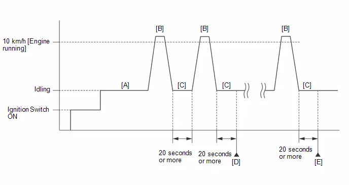
-
Put the engine in Inspection Mode (Maintenance Mode).
Click here

- Warm up the engine (engine coolant temperature of 80°C (176°F) or higher) with the A/C switch and all accessories off [A].
-
While the engine running, drive the Toyota Prius vehicle at a speed of 10 km/h (6 mph) or more [B].
HINT:
If the engine stops, further depress the accelerator pedal to restart the engine.
- Idle the engine for 20 seconds or more [C].
- Repeat procedure [B] and [C].
- Enter the following menus: Powertrain / Engine / Data List / Engine Speed and Engine Independent.
-
Check the Engine Speed when the value of Data List item Engine Independent is "Operate" [D].
Standard:
Engine Idle Speed
950 to 1050 rpm
HINT:
- Be sure to perform this step with the A/C switch and all accessories off.
- Make sure that park (P) is selected.
- If the value of Data List item Engine Independent is "Not Opr" when the engine is idling, charge control is being performed. Check the Engine Speed after charge control is complete ("Operate" is displayed).
- If the idle speed is still out of the specified range, repeat procedure [B] and [C] until the idle speed is within the specified range [E].
-
Put the engine in Inspection Mode (Maintenance Mode).
- *4: Drive the Toyota Prius vehicle for a short while after replacing the knock control sensor and check if knocking occurs. If knocking occurs, drive the vehicle until knocking stops.
Terminals Of Ecm
TERMINALS OF ECM
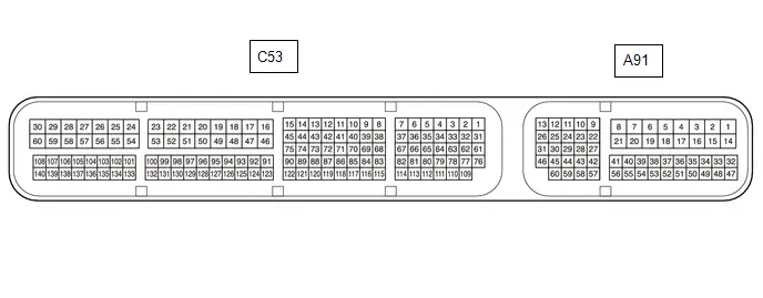
HINT:
The standard voltage, resistance and waveform between each pair of the ECM terminals is shown in the table below. The appropriate conditions for checking each pair of the terminals is also indicated. The result of checks should be compared with the standard voltage, resistance and waveform for each pair of the terminals as displayed in the Specified Condition column. The illustration above can be used as a reference to identify the ECM terminal locations.
| Terminal No. (Symbol) | Terminal Description | Condition | Specified Condition |
|---|---|---|---|
| A91-1 (BATT) - A91-17 (E1) | Auxiliary battery (for measuring auxiliary battery voltage and for ECM memory) | Ignition switch off | 11 to 16 V |
| A91-2 ( B) - A91-17 (E1) | Power source of ECM | Engine stopped, ignition switch ON | 11 to 14 V |
| A91-3 ( B2) - A91-17 (E1) | Power source of ECM | Engine stopped, ignition switch ON | 11 to 14 V |
| A91-9 (CFDH) - A91-17 (E1) | CAN communication line | Engine stopped, ignition switch ON | Pulse generation (See waveform 1) |
| A91-10 (CFDL) - A91-17 (E1) | CAN communication line | Engine stopped, ignition switch ON | Pulse generation (See waveform 2) |
| A91-11 (CFDT) - A91-17 (E1) | CAN communication line | Engine stopped, ignition switch ON | Pulse generation (See waveform 1) |
| A91-12 (CFDB) - A91-17 (E1) | CAN communication line | Engine stopped, ignition switch ON | Pulse generation (See waveform 2) |
| A91-15 (E01) - Body ground | Ground | Always | Below 1 Ω |
| A91-17 (E1) - Body ground | Ground | Always | Below 1 Ω |
| A91-22 (NEO) - A91-17 (E1) | Crankshaft revolution signal | Idling with warm engine | Pulse generation (See waveform 3) |
| A91-23 (G2O) - A91-17 (E1) | Camshaft revolution signal | Idling with warm engine | Pulse generation (See waveform 4) |
| A91-27 (MREL) - A91-17 (E1) | EFI-MAIN relay operation signal | Engine stopped, ignition switch ON | Below 1.5 V |
| A91-28 (FREL) - A91-17 (E1) | Fuel lid lock with motor assembly operation signal | Fuel lid lock with motor assembly operating | Below 1.0 V |
| Fuel lid lock with motor assembly not operating | 11 to 14 V | ||
| A91-29 (FC) - A91-17 (E1) | Fuel pump control | Engine stopped, ignition switch ON | 11 to 14 V |
| Idling | Below 1.5 V | ||
| A91-32 (EC) - Body ground | Ground | Always | Below 1 Ω |
| A91-39 (IGR) - A91-17 (E1) | Ignition signal | Ignitionr switch ON | 11 to 14 V |
| A91-41 (IGP) - A91-17 (E1) | Ignition switch signal | Ignition switch ON | 11 to 14 V |
| A91-42 (FANL) - A91-17 (E1) | Cooling fan motor operation signal (low) | Ignition switch ON | 11 to 14 V |
| Idling, high engine coolant temperature | Below 1.5 V | ||
| A91-43 (FANH) - A91-17 (E1) | Cooling fan motor operation signal (high) | Ignition switch ON | 11 to 14 V |
| Idling, high engine coolant temperature | Below 1.5 V | ||
| A91-60 (FUEL) - A91-17 (E1) | Fuel lid opener switch signal | Fuel lid opener switch pressed | Below 1.0 V |
| Fuel lid opener switch not pressed | 4.5 to 5.5 V | ||
| C53-28 (HA1A) - A91-17 (E1) | Air fuel ratio sensor heater operation signal | Engine stopped, ignition switch ON | 11 to 14 V |
| Idling with cold engine | Pulse generation (See waveform 5) | ||
| C53-29 (M ) - A91-17 (E1) | Throttle actuator operation signal (positive terminal) | Idling with warm engine | Pulse generation (See waveform 6) |
| C53-30 (M-) - A91-17 (E1) | Throttle actuator operation signal (negative terminal) | Idling with warm engine | Pulse generation (See waveform 7) |
| C53-33 (PRG) - A91-17 (E1) | Purge VSV operation signal | Engine stopped, ignition switch ON | 11 to 14 V |
| Idling with warm engine, under purge control | Pulse generation (See waveform 8) | ||
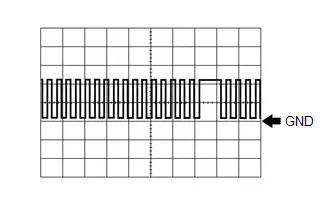
| C53-34 (#10) - A91-15 (E01) | No. 1 fuel injector assembly signal | Idling with warm engine | Pulse generation (See waveform 9) |
| C53-35 (#20) - A91-15 (E01) | No. 2 fuel injector assembly signal | Idling with warm engine | Pulse generation (See waveform 9) |
| C53-36 (#30) - A91-15 (E01) | No. 3 fuel injector assembly signal | Idling with warm engine | Pulse generation (See waveform 9) |
| C53-37 (#40) - A91-15 (E01) | No. 4 fuel injector assembly signal | Idling with warm engine | Pulse generation (See waveform 9) |
| C53-41 (OC1 ) - C53-40 (OC1-) | Camshaft timing oil control valve assembly operation signal | Idling | Pulse generation (See waveform 10) |
| C53-42 (EGR4) - A91-17 (E1) | EGR valve assembly signal | EGR valve assembly operating | Pulse generation (See waveform 11) |
| C53-43 (EGR2) - A91-17 (E1) | EGR valve assembly signal | EGR valve assembly operating | Pulse generation (See waveform 11) |
| C53-44 (EGR3) - A91-17 (E1) | EGR valve assembly signal | EGR valve assembly operating | Pulse generation (See waveform 11) |
| C53-45 (EGR1) - A91-17 (E1) | EGR valve assembly signal | EGR valve assembly operating | Pulse generation (See waveform 11) |
| C53-56 (HT1B) - A91-17 (E1) | Heated oxygen sensor heater operation signal | Engine stopped, ignition switch ON | 11 to 14 V |
| Idling with cold engine | Below 3.0 V | ||
| C53-70 (WPI) - A91-17 (E1) | Electric water pump assembly signal | Idling with warm engine | Pulse generation (See waveform 12) |
| C53-71 (WPO) - A91-17 (E1) | Electric water pump assembly signal | Idling with warm engine | Pulse generation (See waveform 13) |
| C53-72 (IGT4) - A91-17 (E1) | No. 4 ignition coil assembly signal (ignition signal) | Idling with warm engine | Pulse generation (See waveform 14) |
| C53-73 (IGT3) - A91-17 (E1) | No. 3 ignition coil assembly signal (ignition signal) | Idling with warm engine | Pulse generation (See waveform 14) |
| C53-74 (IGT2) - A91-17 (E1) | No. 2 ignition coil assembly signal (ignition signal) | Idling with warm engine | Pulse generation (See waveform 14) |
| C53-75 (IGT1) - A91-17 (E1) | No. 1 ignition coil assembly signal (ignition signal) | Idling with warm engine | Pulse generation (See waveform 14) |
| C53-80 (NE ) - C53-81 (NE-) | Crankshaft position sensor signal | Idling with warm engine | Pulse generation (See waveform 15) |
| C53-82 (VCNE) - A91-17 (E1) | Power source of crankshaft position sensor (specific voltage) | Ignition switch ON | 4.5 to 5.5 V |
| C53-87 (PIM) - C53-88 (EPIM) | Manifold absolute pressure sensor signal | Engine stopped, ignition switch ON | 3.0 to 4.5 V |
| C53-89 (VCPM) - C53-88 (EPIM) | Power source of manifold absolute pressure sensor | Engine stopped, ignition switch ON | 4.75 to 5.25 V |
| C53-92 (KNK1) - C53-91 (EKNK) | Knock control sensor signal | Engine speed maintained at 2500 rpm after warming up engine | Pulse generation (See waveform 16) |
| C53-100 (OX1B) - C53-99 (O1B-) | Heated oxygen sensor signal | Engine speed maintained at 2500 rpm for 2 minutes after warming up engine | Pulse generation (See waveform 17) |
| C53-101 (VTA2) - C53-133 (ETA) | Throttle position sensor signal (for sensor malfunction detection) | Engine stopped, ignition switch ON, accelerator pedal fully released | 2.1 to 3.1 V |
| C53-108 (VCVG) - A91-17 (E1) | Power source of mass air flow meter sub-assembly (specific voltage) | Ignition switch ON | 4.8 to 5.2 V |
| C53-110 (VV1 ) - C53-113 (VV1-) | Camshaft position sensor signal | Idling with warm engine | Pulse generation (See waveform 18) |
| C53-114 (VCV1) - A91-17 (E1) | Power source of camshaft position sensor | Engine stopped, ignition switch ON | 4.5 to 5.5 V |
| C53-124 (THW) - C53-123 (ETHW) | Engine coolant temperature sensor signal | Idling, engine coolant temperature 75 to 100°C (167 to 212°F) | 0.2 to 1.0 V |
| C53-131 (A1A-) - A91-17 (E1) | Air fuel ratio sensor signal | Engine stopped, ignition switch ON | 2.2 to 2.8 V*1 |
| C53-132 (A1A ) - A91-17 (E1) | Air fuel ratio sensor signal | Engine stopped, ignition switch ON | 2.2 to 3.5 V*1 |
| C53-134 (VCTA) - C53-133 (ETA) | Power source of throttle position sensor (specific voltage) | Engine stopped, ignition switch ON | 4.5 to 5.5 V |
| C53-135 (VTA1) - C53-133 (ETA) | Throttle position sensor signal (for engine control) | Engine stopped, ignition switch ON, accelerator pedal fully released | 0.6 to 1.1 V |
| C53-139 (THA) - C53-107 (E2G) | Intake air temperature sensor (mass air flow meter sub-assembly) signal | Idling, intake air temperature 0 to 80°C (32 to 176°F) | 0.5 to 3.4 V |
| C53-140 (VG) - C53-107 (E2G) | Mass air flow meter sub-assembly signal | Ignition switch ON | Pulse generation (See waveform 19) |
*1: The ECM terminal voltage is constant regardless of the voltage output from the sensor.
WAVEFORM 1
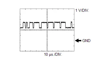 CAN Communication Signal (Reference)
 | ECM Terminal Name | Between CFDH and E1 Between CFDT and E1 |
| Tester Range | 1 V/DIV., 10 μs./DIV. |
| Condition | Engine stopped, ignition switch ON |
HINT:
The waveform varies depending on the CAN communication signal.
WAVEFORM 2
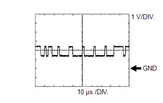 CAN Communication Signal (Reference)
 | ECM Terminal Name | Between CFDL and E1 Between CFDB and E1 |
| Tester Range | 1 V/DIV., 10 μs./DIV. |
| Condition | Engine stopped, ignition switch ON |
HINT:
The waveform varies depending on the CAN communication signal.
WAVEFORM 3
 Crankshaft Revolution Signal from ECM to Inverter with Converter Assembly
 | ECM Terminal Name | Between NEO and E1 |
| Tester Range | 5 V/DIV., 20 ms./DIV. |
| Condition | Idling with warm engine |
HINT:
The wavelength becomes shorter as the engine speed increases.
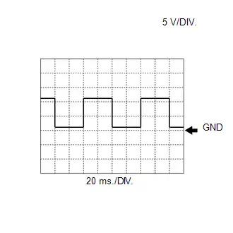
WAVEFORM 4
 Camshaft Revolution Signal from ECM to Inverter with Converter Assembly
 | ECM Terminal Name | Between G2O and E1 |
| Tester Range | 5 V/DIV., 20 ms./DIV. |
| Condition | Idling with warm engine |
HINT:
The wavelength becomes shorter as the engine speed increases.
WAVEFORM 5
 Air Fuel Ratio Sensor Heater Operation Signal
 | ECM Terminal Name | Between HA1A and E1 |
| Tester Range | 5 V/DIV., 10 ms./DIV. |
| Condition | Idling with cold engine |
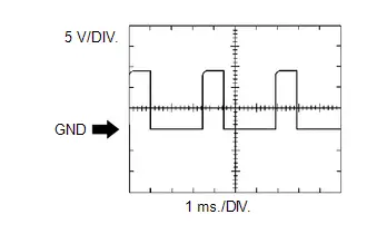
WAVEFORM 6
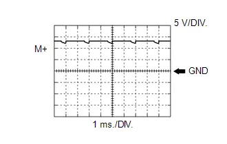 Throttle Actuator Positive Terminal Signal
 | ECM Terminal Name | Between M and E1 |
| Tester Range | 5 V/DIV., 1 ms./DIV. |
| Condition | Idling with warm engine |
HINT:
The duty ratio varies depending on the throttle actuator operation.
WAVEFORM 7
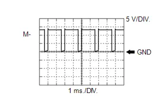 Throttle Actuator Negative Terminal Signal
 | ECM Terminal Name | Between M- and E1 |
| Tester Range | 5 V/DIV., 1 ms./DIV. |
| Condition | Idling with warm engine |
HINT:
The duty ratio varies depending on the throttle actuator operation.
WAVEFORM 8
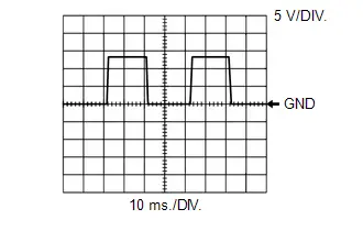
 Purge VSV Operation Signal
 | ECM Terminal Name | Between PRG and E1 |
| Tester Range | 10 V/DIV., 20 ms./DIV. |
| Condition | Idling with warm engine, under purge control |
HINT:
If the waveform is not similar to the illustration, check the waveform again after idling for 10 minutes or more.
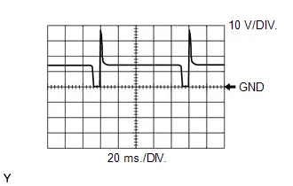
WAVEFORM 9
 No. 1 (to No. 4) Fuel Injector Assembly Signal
 | ECM Terminal Name | Between #10 (to #40) and E01 |
| Tester Range | 20 V/DIV., 20 ms./DIV. |
| Condition | Idling with warm engine |
HINT:
The wavelength becomes shorter as the engine speed increases.
WAVEFORM 10
 Camshaft Timing Oil Control Valve Assembly Operation Signal
 | ECM Terminal Name | Between OC1 and OC1- |
| Tester Range | 5 V/DIV., 1 ms./DIV. |
| Condition | Idling |
WAVEFORM 11
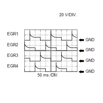 EGR Valve Assembly Signal
 | ECM Terminal Name | Between EGR (1 to 4) and E1 |
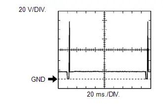
| Tester Range | 20 V/DIV., 50 ms./DIV. |
| Condition | EGR valve assembly operating |
WAVEFORM 12
 Engine Water Pump Assembly Signal (from Engine Water Pump Assembly to ECM)
 | ECM Terminal Name | Between WPI and E1 |
| Tester Range | 5 V/DIV., 20 ms./DIV. |
| Condition | Idling with warm engine |
HINT:
The wavelength becomes shorter as the engine water pump speed increases.
WAVEFORM 13
 Engine Water Pump Assembly Signal (from ECM to Engine Water Pump Assembly)
 | ECM Terminal Name | Between WPO and E1 |
| Tester Range | 5 V/DIV., 20 ms./DIV. |
| Condition | Idling with warm engine |
HINT:
The duty ratio varies depending on the engine water pump assembly speed.
WAVEFORM 14
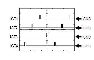 Ignition Coil Assembly Signal (IGT Signal)
 | ECM Terminal Name | Between IGT (1 to 4) and E1 |
| Tester Range | 5 V/DIV., 20 ms./DIV. |
| Condition | Idling with warm engine |
HINT:
The wavelength becomes shorter as the engine speed increases.
WAVEFORM 15
 Crankshaft Position Sensor Signal
 | ECM Terminal Name | Between NE and NE- |
| Tester Range | 2 V/DIV., 20 ms./DIV. |
| Condition | Idling with warm engine |
HINT:
The wavelength becomes shorter as the engine speed increases.
WAVEFORM 16
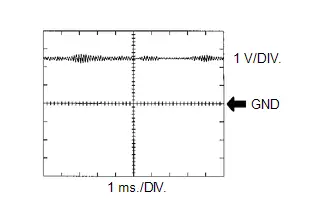 Knock Control Sensor Signal
 | ECM Terminal Name | Between KNK1 and EKNK |
| Tester Range | 1 V/DIV., 1 ms./DIV. |
| Condition | Engine speed maintained at 2500 rpm after warming up engine |
HINT:
- The wavelength becomes shorter as the engine speed increases.
- The waveforms and amplitudes displayed will differ slightly depending on the Toyota Prius vehicle.
WAVEFORM 17
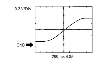 Heated Oxygen Sensor Signal
 | ECM Terminal Name | Between OX1B and O1B- |
| Tester Range | 0.2 V/DIV., 200 ms./DIV. |
| Condition | Engine speed maintained at 2500 rpm for 2 minutes after warming up engine |
HINT:
Data List item "O2 Sensor Voltage B1S2" shows the ECM values from the heated oxygen sensor.
WAVEFORM 18
 Camshaft Position Sensor Signal
 | ECM Terminal Name | Between VV1 and VV1- |
| Tester Range | 5 V/DIV., 20 ms./DIV. |
| Condition | Idling with warm engine |
HINT:
The wavelength becomes shorter as the engine speed increases.
WAVEFORM 19
 Mass Air Flow Meter Sub-assembly Signal
 | ECM Terminal Name | Between VG and E2G |
| Tester Range | 1 V/DIV., 100 μs./DIV. |
| Condition | Ignition switch ON |
Diagnosis System
DIAGNOSIS SYSTEM
EURO-OBD (EUROPEAN SPEC.)

When troubleshooting Europe On-Board Diagnostic (Euro-OBD) vehicles, the vehicle must be connected to an OBD scan tool (complying with ISO 15765-4). Various data output from the Toyota Prius vehicle's ECM can then be read.
Euro-OBD regulations require that the vehicle's on-board computer illuminate the Malfunction Indicator Lamp (MIL) on the instrument panel when the computer detects a malfunction in:
- The emission control system and components.
- The powertrain control components (which affect Toyota Prius vehicle emissions).
- The computer.
In addition, the applicable Diagnostic Trouble Codes (DTCs) prescribed by ISO 15765-4 are stored in the ECM memory. If the malfunction does not reoccur in 3 consecutive trips, the MIL turns off automatically but the DTCs remain stored in the ECM memory.
To check for DTCs, connect the GTS or OBD scan tool to the Data Link Connector 3 (DLC3) of the Toyota Prius vehicle.
The GTS displays DTCs, the freeze frame data and a variety of engine data.
The DTCs and freeze frame data can be cleared using the GTS.
Click here

NORMAL MODE AND CHECK MODE
The diagnosis system operates in normal mode during normal Toyota Prius vehicle use. In normal mode, 2 trip detection logic is used to ensure accurate detection of malfunctions. Check mode is also available as an option for technicians. In check mode, 1 trip detection logic is used for duplicating malfunction symptoms and increasing the system's ability to detect malfunctions, including intermittent problems (GTS only).
2 TRIP DETECTION LOGIC
When a malfunction is first detected, the malfunction is temporarily stored in the ECM memory (1st trip). If the same malfunction is detected during the subsequent drive cycle, the MIL is illuminated (2nd trip).
DLC3 (Data Link Connector 3)
(a) Check the DLC3.
Click here

FREEZE FRAME DATA
The ECM records Toyota Prius vehicle and driving condition information as freeze frame data the moment a DTC is stored. When troubleshooting, freeze frame data can be helpful in determining whether the vehicle was moving or stationary, whether the engine was warmed up or not, whether the air fuel ratio was lean or rich, and other data from the time the malfunction occurred.
AUXILIARY BATTERY VOLTAGE
Standard Voltage:
11 to 16 V
If the voltage is less than 11 V, recharge or replace the auxiliary battery.
MIL (Malfunction Indicator Lamp)
(a) The MIL is illuminated when the ignition switch is turned ON (with the engine is not running).
(b) The MIL will turn off when the ignition switch is turned ON (READY). If the MIL remains illuminated, the diagnosis system has detected a malfunction or abnormality in the system.
HINT:
If the MIL does not illuminate when the ignition switch is turned ON, check the MIL circuit.
Click here

ALL READINESS
HINT:
- With "All Readiness", you can use the GTS to check whether or not DTC judgment has been completed.
- You should check "All Readiness" after simulating malfunction symptoms or for validation after finishing repairs.
(a) Clear the DTCs.
Powertrain > Engine > Clear DTCs(b) Turn the ignition switch off and wait for at least 30 seconds.
(c) Turn the ignition switch ON.
(d) Perform the DTC judgment driving pattern to run the DTC judgment.
(e) Enter the following menus: Powertrain / Engine / Utility / All Readiness.
Powertrain > Engine > Utility| Tester Display |
|---|
| All Readiness |
(f) Input the DTCs to be confirmed.
(g) Check the DTC judgment result.
| GTS Display | Description |
|---|---|
| NORMAL |
|
| ABNORMAL |
|
| INCOMPLETE |
|
Diagnosis Related Information
HINT:
- If the detection conditions of certain DTCs are met before a malfunction can be confirmed, the ECM will store Diagnosis Related Information. Toyota Prius Vehicle condition information from when the detection conditions were met can be checked using the Diagnosis Related Information. Diagnosis Related Information should be used as a reference only, and should not be relied upon solely when determining whether a part is faulty or not.
- Clearing DTCs will also clear Diagnosis Related Information.
- DTCs and Diagnosis Related Information are saved in the GTS at the same time.
(a) Enter the following menus: Powertrain / Engine / Utility / Diagnosis Related Information.
Powertrain > Engine > Utility| Tester Display |
|---|
| Diagnosis Related Information |
(b) Select a Diagnosis Related Information item to display it' s details.
Dtc Check / Clear
DTC CHECK / CLEAR
NOTICE:
When the diagnosis system is changed from normal mode to check mode or vice versa, all DTCs and freeze frame data recorded in normal mode are cleared. Before changing modes, always check and make a note of DTCs and freeze frame data.
HINT:
- DTCs which are stored in the ECM can be displayed on the GTS. The GTS can display the confirmed and pending DTCs.
- Some DTCs are not stored if the ECM does not detect the same malfunction again during a second consecutive driving cycle. However, such malfunctions, detected on only one occasion, are stored as pending DTCs.
CHECK DTC
(a) Enter the following menus: Powertrain / Engine / Trouble Codes.
Powertrain > Engine > Trouble Codes(b) Check the DTC(s) and freeze frame data, and then write them down.
| GTS Display | Description |
|---|---|
| Test Failed | Shows the malfunction judgment results during the current trip. |
| Pending | Shows the malfunction judgment results up to now. (Indicates the possibility of a malfunction when no DTC is confirmed.) |
| Confirmed | Shows the DTCs confirmed up to now. (The number of current trips differs for each DTC.) |
(c) Check the details of the DTC(s).
Click here
![]()
CHECK TIME STAMP
HINT:
By checking Time Stamp, the time and order in which DTCs were stored in an ECU can be checked.
(a) Enter the following menus: Health Check.
(b) Perform the following steps when the data setting screen is displayed.
(c) Select the systems for which to perform Health Check and check for time stamp data.
- Powertrain
- Chassis
- Body
- Store All Data
(d) Select "Yes" when "Do you want to store time stamp data?" is displayed.
HINT:
If "Yes" is not selected, time stamp data will not be stored.
(e) After Health Check has completed, select "Time Stamp Data" to display the Time Stamp screen.
(f) Select the desired system from the drop-down list on the bottom of the Time Stamp screen.
(g) Check the order and time which DTCs were stored for the selected system.
CLEAR DTC
(a) Enter the following menus: Powertrain / Engine / Trouble Codes.
(b) Clear the DTCs.
Powertrain > Engine > Clear DTCsCLEAR DTC (Without using GTS)
(a) Perform either of the following operations:
NOTICE:
After turning ignition switch off, waiting time may be required before disconnecting the cable from the negative (-) auxiliary battery terminal. Therefore, make sure to read the disconnecting the cable from the negative (-) auxiliary battery terminal notices before proceeding with work.
Click here
![]()
![]()
(1) Disconnect the cable from the negative (-) auxiliary battery terminal for more than 1 minute.
(2) Remove the EFI-MAIN and ETCS fuses from the No. 1 engine room relay block and No. 1 junction block assembly located inside the engine compartment for more than 1 minute.
Freeze Frame Data
FREEZE FRAME DATA
DESCRIPTION
The ECM records vehicle and driving condition information as freeze frame data the moment a DTC is stored. When troubleshooting, freeze frame data can be helpful in determining whether the vehicle was moving or stationary, whether the engine was warmed up or not, whether the air fuel ratio was lean or rich, as well as other data recorded at the time of a malfunction.
HINT:
- If it is impossible to replicate the problem even though a DTC is detected, confirm the freeze frame data.
- Freeze frame data is available in long and short forms.
PENDING FREEZE FRAME DATA
HINT:
Pending freeze frame data is stored when a 2 trip detection logic DTC is first detected during the first trip.
(a) Enter the following menus: Powertrain / Engine / Trouble Codes.
(b) Select a DTC in order to display its pending freeze frame data.
Powertrain > Engine > Trouble CodesHINT:
-
Pending freeze frame data is cleared when any of the following occurs.
- Using the GTS, the DTCs cleared.
- The cable is disconnected from the negative (-) auxiliary battery terminal.
- 40 trips with the engine fully warmed up have been performed after returning to normal. (Pending freeze frame data will not be cleared by only returning the system to normal.)
- With previous pending freeze frame data stored, if pending freeze frame data is newly stored when a 2 trip detection logic DTC is detected in the first trip, the old freeze frame data will be replaced with the new data of the newly detected DTC in the next trip.
LIST OF FREEZE FRAME DATA
Powertrain > Engine| Tester Display |
|---|
| Total Distance Traveled |
| Total Distance Traveled - Unit |
| Key Cycle |
| Elapsed Time |
| Toyota Prius Vehicle Speed |
| Engine Speed |
| Calculate Load |
| Vehicle Load |
| Mass Air Flow Sensor |
| Atmospheric Pressure |
| Intake Manifold Absolute Pressure |
| Intake Manifold Absolute Pressure Supported |
| Coolant Temperature |
| Intake Air Temperature |
| Ambient Temperature |
| Engine Run Time |
| IG-ON Coolant Temperature |
| Initial Engine Coolant Temperature |
| IG-ON Intake Air Temperature |
| Initial Engine Intake Air Temperature |
| Battery Voltage |
| BATT Voltage |
| IG2 / IGP |
| IGR |
| Intake Camshaft Position Sensor Voltage |
| Intake Camshaft Position Sensor Speed Bank 1 |
| Crankshaft Position Sensor Voltage |
| Throttle Position Sensor No.1 Voltage % |
| Throttle Position Sensor No.2 Voltage % |
| System Guard |
| Open Side Malfunction |
| Throttle Request Position |
| Throttle Sensor Position |
| Throttle Position Sensor No.1 Voltage |
| Throttle Position Sensor No.2 Voltage |
| Throttle Position Command |
| Throttle Position Sensor Open Position No.1 |
| Throttle Position Sensor Open Position No.2 |
| Throttle Motor Current |
| Throttle Motor Duty Ratio |
| Throttle Motor Duty Ratio (Open) |
| Throttle Motor Duty Ratio (Close) |
| Throttle Position Sensor Fully Closed Learn Value |
| BM Voltage |
| Actuator Power Supply |
| Throttle Air Flow Learn Value (Area 1) |
| Throttle Air Flow Learn Value (Area 2) |
| Throttle Air Flow Learn Value (Area 3) |
| Throttle Air Flow Learn Value (Calculated Value) |
| Throttle Air Flow Learn Value (Atmosphere Pressure Offset Value) |
| Low Revolution Control |
| Engine Stall Control F/B Flow |
| Injector Cylinder #1 (Port) |
| Injection Volume Cylinder #1 |
| Injection Volume |
| Fuel Pump/Speed Status |
| Current Fuel Type |
| EVAP (Purge) VSV |
| Fuel Lid SW |
| Target Air-Fuel Ratio |
| A/F (O2) Lambda Sensor B1S1 |
| A/F (O2) Sensor Current B1S1 |
| A/F (O2) Sensor Heater Duty Ratio B1S1 |
| A/F Sensor Impedance B1S1 |
| O2 Sensor Voltage B1S2 |
| A/F (O2) Sensor Heater Current-Carrying Status B1S2 (at Heater OFF) |
| A/F (O2) Sensor Heater Overcurrent B1S2 |
| A/F (O2) Sensor Heater Control Run Time B1S2 |
| A/F (O2) Sensor Terminal Voltage Bank 1 |
| A/F (O2) Sensor -Terminal Voltage Bank 1 |
| A/F (O2) Sensor Heater Control Duty Ratio Bank1 |
| A/F (O2) Sensor Heater Output Duty Ratio Bank1 |
| A/F (O2) Sensor Heater ON Current Value Bank1 |
| A/F (O2) Sensor Heater Current-Carrying Status Bank1 (at Heater OFF) |
| A/F (O2) Sensor Heater Overcurrent Bank1 |
| A/F (O2) Sensor Heater Control Run Time Bank1 |
| A/F (O2) Sensor Impedance B1S2 |
| O2 Sensor Heater B1S2 |
| A/F (O2) Sensor Heater Current Value B1S2 |
| Short FT B1S1 |
| Short FT B1S2 |
| Long FT B1S1 |
| Long FT B1S2 |
| Total FT Bank 1 |
| Fuel System Status Bank 1 |
| Fuel System Status Bank 2 |
| Ignition Timing Cylinder #1 |
| Knock F/B Value |
| Knock Correct Learn Value |
| Idle Spark Advance Control Cylinder #1 |
| Idle Spark Advance Control Cylinder #2 |
| Idle Spark Advance Control Cylinder #3 |
| Idle Spark Advance Control Cylinder #4 |
| Mass Air Flow Circuit |
| Air Flow Meter Output Frequency |
| Target EGR Valve Position No.1 |
| Target EGR Valve Position No.1 Supported |
| Actual EGR Valve Position No.1 Supported |
| Target EGR Valve Position No.2 Supported |
| Actual EGR Valve Position No.2 Supported |
| EGR Step Position |
| VVT Advance Fail |
| Intake VVT Hold Learn Value Bank 1 |
| Intake VVT Change Angle Bank 1 |
| Intake VVT OCV Control Duty Ratio Bank 1 |
| Intake VVT Target Angle Bank 1 |
| Intake VVT Timing Most Over-Retarded Learn Value Bank 1 |
| Catalyst Temperature B1S1 |
| Catalyst Temperature B1S2 |
| TC Terminal |
| MIL ON Run Distance |
| Running Time from MIL ON |
| Time after DTC Cleared |
| Distance from DTC Cleared |
| Warmup Cycle Cleared DTC |
| Distance Traveled from Last Battery Cable Disconnect |
| IG OFF Elapsed Time |
| Soak IC Current Timer Value |
| Ignition Trigger Count |
| Misfire Count Cylinder #1 |
| Misfire Count Cylinder #2 |
| Misfire Count Cylinder #3 |
| Misfire Count Cylinder #4 |
| All Cylinders Misfire Count |
| Misfire RPM |
| Misfire Load |
| Misfire Margin |
| Catalyst OT Misfire Fuel Cut |
| Catalyst OT Misfire Fuel Cut History |
| Catalyst OT Misfire Fuel Cut Cylinder #1 |
| Catalyst OT Misfire Fuel Cut Cylinder #2 |
| Catalyst OT Misfire Fuel Cut Cylinder #3 |
| Catalyst OT Misfire Fuel Cut Cylinder #4 |
| IG ON Duration Time |
| IG OFF Duration Time |
| Engine Start Hesitation |
| Low Revolution for Engine Start |
| A/F Learn Value Idle Bank 1 |
| A/F Learn Value Low Bank 1 |
| A/F Learn Value Mid No.1 Bank 1 |
| A/F Learn Value Mid No.2 Bank 1 |
| A/F Learn Value High Bank 1 |
| Engine ECU Internal Temperature |
| Engine Cooling Fan |
| Engine Speed Cylinder #1 |
| Engine Speed Cylinder #2 |
| Engine Speed Cylinder #3 |
| Engine Speed Cylinder #4 |
| Average Engine Speed of All Cylinder |
| Requested Engine Torque |
| HV Target Engine Speed |
| Actual Engine Torque |
| Engine Driving Time |
| Request Engine Run Time |
| Judge Time Engine Ignition |
| Judge Time Engine Output |
| Fuel Level |
| ISC Learning Value |
| ISC Learning |
| F/C for Engine Stop Req |
| Engine Independent |
| Racing Operation |
| Request Warm-up |
| Engine Independent Control |
| Electric Water Pump Target Speed |
| Electric Water Pump Speed |
Check Mode Procedure
CHECK MODE PROCEDURE
HINT:
Compared to normal mode, check mode is more sensitive to malfunctions. Therefore, check mode can detect malfunctions that cannot be detected in normal mode.
NOTICE:
All of the stored DTCs and freeze frame data are cleared if: 1) the ECM is changed from normal mode to check mode or vice versa; or 2) the ignition switch is turned from ON to ACC or off while in check mode. Before changing modes, always check for and note any DTCs and freeze frame data.
CHECK MODE PROCEDURE
(a) Check and ensure the following conditions:
(1) Auxiliary battery voltage is 11 V or higher.
(2) Accelerator pedal fully released.
(3) Park (P) is selected.
(4) A/C switch is off.
(b) Turn the ignition switch off.
(c) Turn the ignition switch ON.
(d) Enter the following menus: Powertrain / Engine / Utility / Check Mode.
Powertrain > Engine > Utility| Tester Display |
|---|
| Check Mode |
(e) Change the ECM from normal mode to check mode.
(f) Check that the MIL flashes as shown in the illustration.
(g) Turn the ignition switch ON (READY).
(h) Check that the MIL turns off.
(i) Simulate the conditions of the malfunction described by the customer.
(j) Check for DTCs and freeze frame data using the GTS.
Fail-safe Chart
FAIL-SAFE CHART
If any of the following DTCs are stored, the ECM enters fail-safe mode to allow the vehicle to be driven temporarily or stops fuel injection.
| DTC Code | Component | Fail-Safe Operation | Fail-Safe Deactivation Condition |
|---|---|---|---|
| P001100 | VVT system | Idle up (control of combustion decreased). | Pass condition detected |
| P003012 P003013 P101A9E | Air fuel ratio sensor heater | The ECM turns off the air fuel ratio sensor heater. | Ignition switch off |
| P003612 P003614 P102A9E | Heated oxygen sensor heater | The ECM turns off the heated oxygen sensor heater. | Ignition switch off |
| P006900 P222611 P222615 P222687 P222696 |
| The ECM maintains the last learned atmospheric pressure value. | Pass condition detected |
| P010012 P010014 | Mass air flow meter sub-assembly | The ECM calculates ignition timing according to the engine speed and throttle valve position. | Pass condition detected |
| P010511 P010515 | Manifold absolute pressure sensor | The ECM disables EGR valve operation | Pass condition detected |
| P011011 P011015 | Intake air temperature sensor | The ECM estimates the intake air temperature to be 20°C (68°F). | Pass condition detected |
| P011511 P011515 P01152A | Engine coolant temperature sensor | The ECM estimates the engine coolant temperature to be 80°C (176°F). | Pass condition detected |
| P012011 P012015 P01201C P022011 P022015 P060444 P060647 P060747 P060787 P060E49 P065714 P06579E P16B09F P210018 P210019 P211900 P211904 P211977 P21199B P21352B | Electronic throttle control system | The ECM cuts off throttle actuator current and the throttle valve is returned to a 6.5° throttle position by the return spring. The ECM controls the fuel injection duration and ignition timing in accordance with the engine torque requested by the hybrid Toyota Prius vehicle control ECU. Fuel-cut is performed intermittently.*1 | Pass condition detected and then ignition switch turned off |
| P030000 P030027 P030085 P030100 P030200 P030300 P030400 *2 |
| When a catalyst-damaging misfire occurs (MIL blinking), the following fail-safe operation is performed for catalyst overheat malfunction prevention.
| Pass condition detected and then ignition switch turned off |
| P032511 P032515 | Knock control sensor | The ECM sets the ignition timing to maximum retard. | Ignition switch off |
| P04019C P040314 P140000 P140596 P141004 | EGR valve assembly | The ECM fully closes the EGR valve and stops EGR control. | Pass condition detected |
| P211172 P211173 | Electronic throttle control system | The ECM stops the engine and the Toyota Prius vehicle can be driven using solely the hybrid system.*1 | Pass condition detected and then ignition switch turned off |
| P223700 P223711 P223712 P223713 P22371B P225111 P225112 | Air fuel ratio sensor | Air fuel ratio feedback control is stopped. | Pass condition detected and then ignition switch turned off |
| P26CA12 P26CA31 P26CB71 | Inverter water pump with motor assembly |
| Pass condition detected and then ignition switch is turned off |
| P26CA14 | Inverter water pump with motor assembly |
| Pass condition detected and then ignition switch is turned off |
| P26CE37 | Inverter water pump with motor assembly | The inverter water pump with motor assembly is temporarily operated and stopped in a repeating cycle.
| Pass condition detected and then ignition switch is turned off |
HINT:
- *1: The Toyota Prius vehicle can be driven slowly when the accelerator pedal is depressed firmly and slowly.
- *2: Misfire-related fail-safe operations occur when catalyst overheat malfunctions occur.
Data List / Active Test
DATA LIST / ACTIVE TEST
DATA LIST
HINT:
Using the GTS to read the Data List allows the values or states of switches, sensors, actuators and other items to be read without removing any parts. This non-intrusive inspection can be very useful because intermittent conditions or signals may be discovered before parts or wiring is disturbed. Reading the Data List information early in troubleshooting is one way to save diagnostic time.
NOTICE:
In the table below, the values listed under "Normal Condition" are reference values. Do not depend solely on these reference values when deciding whether a part is faulty or not.
(a) Put the engine in Inspection Mode (Maintenance Mode).
Powertrain > Hybrid Control > Utility| Tester Display |
|---|
| Inspection Mode |
(b) Start the engine.
(c) Warm up the engine.
(d) Turn the A/C switch off.
(e) Turn the ignition switch off.
(f) Turn the ignition switch ON.
(g) Enter the following menus: Powertrain / Engine / Data List.
HINT:
- To display the list box, press the pull down menu button next to Primary. Then select a measurement group.
- When you select a measurement group, the ECU data belonging to that group is displayed.
-
Measurement Group List / Description
- All Data / All data
- Primary / -
- Engine Control / Engine control system related data
- Ptrl General / -
- Ptrl AF Control / Air fuel ratio control system related data
- Ptrl AF O2 Sensor / Air fuel ratio sensor and heated oxygen sensor related data
- Ptrl Throttle / Gasoline throttle system related data
- Ptrl Intake Control / Intake control system related data
- Ptrl Valve Control / Valve control system related data
- Ptrl Misfire / "Misfire" related data
- Ptrl Starting / "Difficult to start" related data
- Ptrl Rough Idle / "Rough idle" related data
- Ptrl Evaporative / Evaporative system related data
- Ptrl CAT Converter / Catalyst converter related data
- Check Mode / Check mode related data
- Monitor Status / Monitor status related data
- Ignition / Ignition system related data
- Charging Control / Charging control system related data
- Compression / Data used during "Check the Cylinder Compression" Active Test
- AT / Automatic transaxle system related data
- Toyota Prius Vehicle Information / Vehicle information
(h) Read the Data List according to the display on the GTS.
HINT:
The title used for each group of Data List items in this repair manual does not appear on the GTS. However, the name in parentheses after the title, which is a Measurement Group, does appear on the GTS. When the name shown in parentheses is selected on the GTS, all of the Data List items listed for that group will be displayed.
Various Toyota Prius Vehicle Conditions 1 (All Data)
Powertrain > Engine > Data List| Tester Display | Measurement Item | Range | Normal Condition | Diagnostic Note |
|---|---|---|---|---|
| Total Distance Traveled | Total distance traveled | Min.: 0, Max.: 16777215 | - | - |
| Total Distance Traveled - Unit | Total Distance Traveled unit | km or mile | - | - |
| Toyota Prius Vehicle Speed | Vehicle speed | Min.: 0 km/h (0 mph), Max.: 255 km/h (158 mph) | Actual vehicle speed | This is the current vehicle speed. |
| Engine Speed | Engine speed | Min.: 0 rpm, Max.: 16383 rpm | 950 to 1050 rpm: Idling with warmed up engine (inspection mode [maintenance mode], not charge control, park (P) selected) | When the crankshaft position sensor is malfunctioning, "Engine Speed" is approximately 0 rpm or varies greatly from the actual engine speed. |
| Calculate Load | Load calculated by ECM | Min.: 0%, Max.: 100% |
|
|
| Toyota Prius Vehicle Load | Vehicle load | Min.: 0%, Max.: 25700% | Actual vehicle load |
HINT: Due to individual engine differences, intake air temperature, etc., the value may exceed 100%. Intake airflow (g/rev.) = Intake airflow (gm/sec) x 60 / Engine speed (rpm) (Intake airflow (gm/sec) is value of Mass Air Flow Sensor) |
| Mass Air Flow Sensor | Airflow rate from mass air flow meter sub-assembly | Min.: 0 gm/sec, Max.: 655.35 gm/sec |
| This is the intake air amount measured by the mass air flow meter sub-assembly. |
| Atmospheric Pressure | Atmospheric pressure | Min.: 0 kPa (0 psi), Max.: 255 kPa (37 psi) | Equivalent to atmospheric pressure |
|
| Intake Manifold Absolute Pressure | Intake manifold absolute pressure | Min.: 0 kPa (0 psi), Max.: 2047.96 kPa (296.95 psi) |
|
HINT: When the ignition switch ON, the manifold absolute pressure and atmospheric pressure are approximately the same (standard atmospheric pressure = 101 kPa(abs) [15 psi(abs)]). |
| Intake Manifold Absolute Pressure Supported | Status of Intake Manifold Absolute Pressure | Unsupp or Supp | Supp | - |
| Coolant Temperature | Engine coolant temperature | Min.: -40°C (-40°F), Max.: 140°C (284°F) | 75 to 100°C (167 to 212°F): After warming up | This is the engine coolant temperature. HINT:
|
| Intake Air Temperature | Intake air temperature | Min.: -40°C (-40°F), Max.: 140°C (284°F) | Equivalent to temperature at location of mass air flow meter sub-assembly | This is the engine intake air temperature. HINT:
|
| Ambient Temperature | Ambient temperature | Min.: -40°C (-40°F), Max.: 215°C (419°F) | Equivalent to ambient temperature | This is the ambient temperature. HINT: After a long soak, the engine coolant temperature, intake air temperature and ambient air temperature will be approximately equal. |
| Engine Run Time | Engine run time | Min.: 0 sec, Max.: 65535 sec | Time after engine start |
|
| IG-ON Coolant Temperature | Engine coolant temperature when the ignition switch is turned ON | Min.: -40°C (-40°F), Max.: 119.3°C (246.7°F) | - | This is the engine coolant temperature stored when the ignition switch is turned ON. |
| Initial Engine Coolant Temperature | Engine coolant temperature when the ignition switch is turned ON (READY) | Min.: -40°C (-40°F), Max.: 119.3°C (246.7°F) | - | This is the engine coolant temperature stored when the ignition switch is turned ON (READY). |
| IG-ON Intake Air Temperature | Intake air temperature when the ignition switch is turned ON | Min.: -40°C (-40°F), Max.: 119.3°C (246.7°F) | - | This is the intake air temperature stored when the ignition switch is turned ON |
| Initial Engine Intake Air Temperature | Intake air temperature when the ignition switch is turned ON (READY) | Min.: -40°C (-40°F), Max.: 119.3°C (246.7°F) | - | This is the intake air temperature stored when the ignition switch is turned ON (READY). |
| Battery Voltage | Auxiliary battery voltage | Min.: 0 V, Max.: 65.5 V | 11 to 16 V: Ignition switch ON | If 11 V or less, characteristics of some electrical components may change. |
| BATT Voltage | Auxiliary battery voltage | Min.: 0 V, Max.: 79.998 V | 11 to 16 V: Ignition switch ON | If 11 V or less, characteristics of some electrical components may change. |
| IG2 / IGP | Status of IGP terminal | ON or OFF | ON: Ignition switch ON | - |
| IGR | Status of IGR terminal | ON or OFF | ON: Ignition switch ON | - |
| Intake Camshaft Position Sensor Voltage | Camshaft position sensor voltage | Min.: 0 V, Max.: 4.999 V | - | - |
| Intake Camshaft Position Sensor Speed Bank 1 | Intake camshaft speed | Min.: 0 rpm, Max.: 65535 rpm | - | - |
| Crankshaft Position Sensor Voltage | Crankshaft position sensor voltage | Min.: 0 V, Max.: 4.999 V | - | - |
Throttle Control (All Data)
Powertrain > Engine > Data List| Tester Display | Measurement Item | Range | Normal Condition | Diagnostic Note |
|---|---|---|---|---|
| Throttle Position Sensor No.1 Voltage % | Absolute No. 1 throttle position sensor | Min.: 0%, Max.: 100% | 10 to 22%: Ignition switch ON, accelerator pedal fully released | The No. 1 throttle position sensor output is converted using 5 V = 100%. HINT: If there are no throttle position sensor DTCs stored, it is possible to conclude that the throttle position sensor system is normal. |
| Throttle Position Sensor No.2 Voltage % | Absolute No. 2 throttle position sensor | Min.: 0%, Max.: 100% | 42 to 62%: Ignition switch ON, accelerator pedal fully released | The No. 2 throttle position sensor output is converted using 5 V = 100%. |
| System Guard | System guard | ON or OFF | ON: Idling or throttle actuator operating |
|
| Open Side Malfunction | Open malfunction | ON or OFF | OFF | This item indicates a malfunction in the electronic throttle when the throttle valve is open. |
| Throttle Request Position | Required throttle position | Min.: 0 V, Max.: 4.98 V | 0.6 to 1.1 V: Idling with warmed up engine (inspection mode [maintenance mode]) | The value of this item is calculated by the ECM and shows the voltage for the target throttle valve position. |
| Throttle Sensor Position | Throttle sensor position | Min.: 0%, Max.: 100% | - | - |
| Throttle Position Sensor No.1 Voltage | No. 1 throttle position sensor output voltage | Min.: 0 V, Max.: 4.98 V |
| This is the No. 1 throttle position sensor output voltage. |
| Throttle Position Sensor No.2 Voltage | No. 2 throttle position sensor output voltage | Min.: 0 V, Max.: 4.98 V |
| This is the No. 2 throttle position sensor output voltage. |
| Throttle Position Command | Throttle position command value | Min.: 0 V, Max.: 4.98 V | 0.6 to 1.1 V: Idling with warmed up engine (inspection mode [maintenance mode]) | The value displayed for this item is the same as Throttle Request Position. |
| Throttle Position Sensor Open Position No.1 | No. 1 throttle position sensor | Min.: 0 V, Max.: 4.98 V | 0.6 to 1.4 V | This is the No. 1 throttle position sensor output voltage when there is no current supplied to the electronic throttle actuator. If the accelerator pedal is released the throttle valve is kept open by the throttle valve opener when the ignition switch ON. |
| Throttle Position Sensor Open Position No.2 | No. 2 throttle position sensor | Min.: 0 V, Max.: 4.98 V | 1.7 to 2.5 V | This is the No. 2 throttle position sensor output voltage when there is no current supplied to the electronic throttle actuator. If the accelerator pedal is released the throttle valve is kept open by the throttle valve opener when the ignition switch ON. |
| Throttle Motor Current | Throttle actuator current | Min.: 0 A, Max.: 19.9 A | 0 to 3.0 A: Idling with warmed up engine (inspection mode [maintenance mode]) | When the value of this item is large but the actual opening angle (Throttle Position Sensor No.1 Voltage) does not reach the target opening angle (Throttle Request Position), there is an "unable to open" malfunction. |
| Throttle Motor Duty Ratio | Throttle actuator | Min.: 0%, Max.: 100% | 10 to 22%: Idling with warmed up engine (inspection mode [maintenance mode]) | This is the output duty ratio of the throttle actuator drive circuit. |
| Throttle Motor Duty Ratio (Open) | Throttle actuator duty ratio (open) | Min.: 0%, Max.: 255% | 0 to 40%: Idling with warmed up engine (inspection mode [maintenance mode]) | This is the duty ratio used to drive the throttle actuator and open the throttle valve. It is an ECM command signal. |
| Throttle Motor Duty Ratio (Close) | Throttle actuator duty ratio (close) | Min.: 0%, Max.: 255% | 0 to 40%: Idling with warmed up engine (inspection mode [maintenance mode]) | This is the duty ratio used to drive the throttle actuator and close the throttle valve. It is an ECM command signal. HINT: During idle, the throttle valve opening angle is usually controlled using a duty ratio drive signal which closes the throttle valve. However, if carbon deposits have built up, it may be necessary to open the throttle valve more than the throttle valve opener does. In that case, the opening angle is controlled using the Throttle Motor Duty Ratio (Open) signal. |
| Throttle Position Sensor Fully Closed Learn Value | Throttle valve fully closed position (learned value) | Min.: 0 V, Max.: 4.98 V | 0.4 to 1.0 V: Ignition switch ON, accelerator pedal fully released |
|
| BM Voltage | BM voltage | Min.: 0 V, Max.: 79.998 V | 11 to 16 V: Ignition switch ON | This is the power supply for the electronic throttle actuator. When the power supply is interrupted for approximately 1 second, DTCs P065714 (open circuit) and P06579E (short circuit, ECU malfunction) are stored and the electronic throttle control system enters fail-safe mode (normal operation is not restored until the ignition switch is turned off). |
| Actuator Power Supply | Actuator power supply | ON or OFF | ON: Engine running or throttle actuator operating | - |
| Throttle Air Flow Learn Value (Area 1) | Throttle air flow learning value of area 1 | Min.: 0, Max.: 1.99 | - | - |
| Throttle Air Flow Learn Value (Area 2) | Throttle air flow learning value of area 2 | Min.: 0, Max.: 1.99 | - | - |
| Throttle Air Flow Learn Value (Area 3) | Throttle air flow learning value of area 3 | Min.: 0, Max.: 1.99 | - | - |
| Throttle Air Flow Learn Value (Calculated Value) | Throttle air flow learning value (calculated value) | Min.: 0, Max.: 1.99 | - | - |
| Throttle Air Flow Learn Value (Atmosphere Pressure Offset Value) | Throttle air flow learning value (atmosphere pressure offset value) | Min.: 0, Max.: 2.55 | - | - |
Idle Speed Control (Ptrl Rough Idle)
Powertrain > Engine > Data List| Tester Display | Measurement Item | Range | Normal Condition | Diagnostic Note |
|---|---|---|---|---|
| Low Revolution Control | Low engine speed control operation state | ON or OFF | OFF | This item indicates whether the engine speed dropped immediately after starting due to poor combustion, etc. |
| Engine Stall Control F/B Flow | ISC torque lower limit value to prevent engine stall | Min.: -1024 Nm, Max.: 1023.96 Nm | - |
|
Fuel System (All Data)
Powertrain > Engine > Data List| Tester Display | Measurement Item | Range | Normal Condition | Diagnostic Note |
|---|---|---|---|---|
| Injector Cylinder #1 (Port) | Injection period of the No. 1 cylinder | Min.: 0 μs, Max.: 65535 μs | 1000 to 3000 μs: Idling with warmed up engine (inspection mode [maintenance mode], not charge control) | This is the injection period of the No. 1 cylinder (the command value from the ECM). |
| Injection Volume Cylinder #1 | Injection volume (cylinder 1) | Min.: 0 ml, Max.: 2 ml | 0.03 to 0.13 ml: Idling with warmed up engine (inspection mode [maintenance mode], not charge control) | This is the fuel injection volume for 10 injections. |
| Injection Volume | Fuel injection volume | Min.: -25%, Max.: 24.8% | - | Active Test [Control the Injection Volume for A/F Sensor] support data. |
| Engine Fuel Rate | Fuel consumption (engine) | Min.: 0 gm/sec, Max.: 1310.7 gm/sec | - | - |
| Toyota Prius Vehicle Fuel Rate | Fuel consumption (vehicle) | Min.: 0 gm/sec, Max.: 1310.7 gm/sec | - | - |
| Fuel Pump/Speed Status | Fuel pump status | ON or OFF | ON: Engine running | - |
| Current Fuel Type | Current fuel type | - | Gasoline/petrol | - |
EVAP System (Ptrl Evaporative)
Powertrain > Engine > Data List| Tester Display | Measurement Item | Range | Normal Condition | Diagnostic Note |
|---|---|---|---|---|
| EVAP (Purge) VSV | Purge VSV control duty | Min.: 0%, Max.: 100% | 10 to 70%: Idling with warmed up engine (inspection mode [maintenance mode]) |
|
| EVAP Purge Flow | Purge flow | Min.: 0%, Max.: 399.9% | - | This is the percentage of total engine airflow contributed by EVAP purge operation. (Evap Purge Flow = Purge flow / Engine airflow x 100 (%)) |
| EVAP Purge Density Learn Value | Purge density learned value | Min.: -200, Max.: 199.993 | - |
HINT:
|
| Fuel Lid SW | Fuel lid courtesy switch status | Open or Close |
| This item is displayed only with Canister Pump Module models. |
| EVAP Purge VSV | VSV status for EVAP control | ON or OFF | - | This item is ON when EVAP (Purge) VSV is approximately 30% or higher, and is OFF when the VSV duty ratio is less than 30%. |
| Purge Cut VSV Duty | Purge VSV duty | Min.: 0%, Max.: 399.9% | - | - |
Air Fuel Ratio Control 1 (All Data)
Powertrain > Engine > Data List| Tester Display | Measurement Item | Range | Normal Condition | Diagnostic Note |
|---|---|---|---|---|
| Target Air-Fuel Ratio | Target air fuel ratio | Min.: 0, Max.: 2 | 0.8 to 1.2: During idling (engine warmed up) |
|
Air Fuel Ratio Control 2 (Ptrl AF O2 Sensor)
Powertrain > Engine > Data List| Tester Display | Measurement Item | Range | Normal Condition | Diagnostic Note |
|---|---|---|---|---|
| A/F (O2) Lambda Sensor B1S1 | Output air fuel ratio associated | Min.: 0, Max.: 1.99 |
| This is the actual air fuel ratio calculated based on the air fuel ratio sensor output. |
| A/F (O2) Sensor Current B1S1 | Air fuel ratio sensor output current | Min.: -128 mA, Max.: 127.99 mA | -0.5 to 0.5 mA: Idling with warmed up engine (inspection mode [maintenance mode]) |
|
| A/F (O2) Sensor Heater Duty Ratio B1S1 | Air fuel ratio sensor heater duty ratio | Min.: 0%, Max.: 399.9% | 0 to 100% | When the value of this item is more than 0%, current is being supplied to the heater. |
| A/F Sensor Impedance B1S1 | Air fuel ratio sensor impedance | Min.: 0 ohm, Max.: 21247.67 ohm | 5 to 15000 ohm: Idling with warmed up engine (inspection mode [maintenance mode]) | - |
| O2 Sensor Voltage B1S2 | Heated oxygen sensor output voltage | Min.: 0 V, Max.: 1.275 V | 0 to 1.0 V |
|
| A/F (O2) Sensor Heater Current-Carrying Status B1S2 (at Heater OFF) | Air fuel ratio sensor heater off energizing status | ON or OFF | OFF: Ignition switch ON | - |
| A/F (O2) Sensor Heater Overcurrent B1S2 | Air fuel ratio sensor heater overcurrent | ON or OFF | OFF | - |
| A/F (O2) Sensor Heater Control Run Time B1S2 | Time elapsed since air fuel ratio sensor heater control started | Min.: 0 ms, Max.: 536862 ms | - | - |
| A/F (O2) Sensor Terminal Voltage Bank 1 | Air fuel ratio sensor positive terminal voltage | Min.: 0 V, Max.: 79.998 V | - | - |
| A/F (O2) Sensor -Terminal Voltage Bank 1 | Air fuel ratio sensor negative terminal voltage | Min.: 0 V, Max.: 79.998 V | - | - |
| A/F (O2) Sensor Heater Control Duty Ratio Bank1 | Air fuel ratio sensor heater control duty ratio | Min.: -327.68%, Max.: 327.67% | - |
|
| A/F (O2) Sensor Heater Output Duty Ratio Bank1 | Air fuel ratio sensor heater output duty ratio | Min.: 0%, Max.: 399.99% | - |
|
| A/F (O2) Sensor Heater ON Current Value Bank1 | Air fuel ratio sensor heater on output current | Min.: 0 A, Max.: 65.535 A | -0.5 to 0.5 mA: Idling with engine warmed up (inspection mode [maintenance mode], not charge control) | - |
| A/F (O2) Sensor Heater Current-Carrying Status Bank1 (at Heater OFF) | Air fuel ratio sensor heater off energizing status | ON or OFF | OFF: Ignition switch ON | - |
| A/F (O2) Sensor Heater Overcurrent Bank1 | Air fuel ratio sensor heater overcurrent | ON or OFF | OFF | - |
| A/F (O2) Sensor Heater Control Run Time Bank1 | Time elapsed since air fuel ratio sensor heater control started | Min.: 0 ms, Max.: 65535 ms | - | - |
| A/F (O2) Sensor Impedance B1S2 | Air fuel ratio sensor impedance | Min.: 0 ms, Max.: 21247.67 ohm | 5 to 15000 ohm: Idling with warmed up engine (inspection mode [maintenance mode]) | - |
| O2 Sensor Heater B1S2 | Heated oxygen sensor heater | Active or Not Act | Active: Heater on | - |
| A/F (O2) Sensor Heater Current Value B1S2 | Heated oxygen sensor current | Min.: 0 A, Max.: 4.999 A | - | When the value of this item is more than 0 A, current is being supplied to the heater. |
| Short FT B1S1 | Short-term fuel trim | Min.: -100%, Max.: 99.21% | -20 to 20% | This item is the "short-term fuel injection volume compensation ratio" used to maintain the air fuel ratio at the stoichiometric ratio using the air fuel ratio sensor for feedback. |
| Short FT B1S2 | Short-term fuel trim | Min.: -100%, Max.: 99.21% | - | - |
| Long FT B1S1 | Long-term fuel trim | Min.: -100%, Max.: 99.21% | -20 to 20% |
|
| Long FT B1S2 | Long-term fuel trim | Min.: -100%, Max.: 99.21% | - | - |
| Total FT Bank 1 | Total fuel trim | Min.: -0.5, Max.: 0.496 | -0.28 to 0.2: Idling with warmed up engine (inspection mode [maintenance mode]) | Total FT Bank 1 = Short FT B1S1 Long FT B1S1 |
| Fuel System Status Bank 1 | Fuel system status (bank 1) | Unused, OL, CL, OLDrive, OLFault or CLFault | CL: Idling after warming up |
HINT: CL (Closed Loop): During air fuel ratio feedback control, A/F (O2) Lambda Sensor B1S1 is approximately 1.0 and A/F (O2) Sensor Voltage B1S1 is approximately 3.3 V. |
| Fuel System Status Bank 2 | Fuel system status (bank 2) | Unused, OL, CL, OLDrive, OLFault or CLFault | Unused | - |
| A/F Learn Value Idle Bank 1 | Air fuel ratio learn value of idle area | Min.: -50%, Max.: 49.6% | -20 to 20% | Learning is performed when idling with the engine warmed up (engine coolant temperature is 80°C [176°F] or higher). |
| A/F Learn Value Low Bank 1 | Air fuel ratio learn value of low load area | Min.: -50%, Max.: 49.6% | -20 to 20% | Learning is performed when driving with the engine warmed up (engine coolant temperature is 80°C [176°F] or higher) and operating in the low load range (when the range of engine loads is divided into four parts). |
| A/F Learn Value Mid No.1 Bank 1 | Air fuel ratio learn value of middle 1 load area | Min.: -50%, Max.: 49.6% | -20 to 20% | Learning is performed when driving with the engine warmed up (engine coolant temperature is 80°C [176°F] or higher) and operating in the medium load range closer to the low load range (when the range of engine loads is divided into four parts). |
| A/F Learn Value Mid No.2 Bank 1 | Air fuel ratio learn value of middle 2 load area | Min.: -50%, Max.: 49.6% | -20 to 20% | Learning is performed when driving with the engine warmed up (engine coolant temperature is 80°C [176°F] or higher) and operating in the medium load range closer to the high load range (when the range of engine loads is divided into four parts). |
| A/F Learn Value High Bank 1 | Air fuel ratio learn value of high load area | Min.: -50%, Max.: 49.6% | -20 to 20% | Learning is performed when driving with the engine warmed up (engine coolant temperature is 80°C [176°F] or higher) and operating in the high load range (when the range of engine loads is divided into four parts). |
Ignition System (Ignition)
Powertrain > Engine > Data List| Tester Display | Measurement Item | Range | Normal Condition | Diagnostic Note |
|---|---|---|---|---|
| Ignition Timing Cylinder #1 | Ignition timing advance for No. 1 cylinder | Min.: -64 deg, Max.: 63.5 deg | 8 to 24 deg: Idling with warmed up engine (inspection mode [maintenance mode], not charge control) | - |
| Knock F/B Value | Knocking feedback value | Min.: -1024 deg(CA), Max.: 1023.9 deg(CA) | -20 to 0 deg(CA): Driving at 70 km/h (43 mph) (Engine running) | This is the ignition timing retard compensation amount determined by the presence or absence of knocking. Ignition timing = Most retarded timing value*1 Knock Correct Learn Value*2 Knock F/B Value*3 each compensation amount Example: 21 deg(CA) = 10 deg(CA) 14 deg(CA) - 3 deg(CA) *1: The most retarded timing value is a constant determined by the engine speed and engine load. *2: The knock correction learned value is calculated as shown below in order to keep Knock F/B Value as close to -3 deg(CA) as possible. When Knock F/B Value is less than -4 deg(CA), Knock Correct Learn Value is slowly decreased. When Knock F/B Value is higher than -2 deg(CA), Knock Correct Learn Value is slowly increased. *3: The base value is -3 deg(CA) and is adjusted based on the presence or absence of knocking. When there is no knocking, the value is increased, and when knocking is present, the value is decreased. HINT: If Knock F/B Value does not change around the time when knocking occurs even though knocking continues (for example, stays at -3 deg(CA)), it can be determined that knocking is not being detected. Possible Causes:
|
| Knock Correct Learn Value | Knocking correction learned value | Min.: -1024 deg(CA), Max.: 1023.9 deg(CA) | 0 to 22 deg(CA): Driving at 70 km/h (43 mph) (Engine running) |
HINT: When knocking continues even though Knock Correct Learn Value is less than that of the Toyota Prius vehicle being used for comparison (in other words, the ignition timing is being retarded but the knocking does not stop), there may be a buildup of deposits or other such problems due to deterioration over time (oil entering the cylinders, poor quality fuel, etc.). |
| Idle Spark Advance Control Cylinder #1 | Individual cylinder timing advance compensation amount (No. 1) | Min.: 0 deg(CA), Max.: 15.93 deg(CA) | - |
|
| Idle Spark Advance Control Cylinder #2 | Individual cylinder timing advance compensation amount (No. 2) | Min.: 0 deg(CA), Max.: 15.93 deg(CA) | - |
|
| Idle Spark Advance Control Cylinder #3 | Individual cylinder timing advance compensation amount (No. 3) | Min.: 0 deg(CA), Max.: 15.93 deg(CA) | - |
|
| Idle Spark Advance Control Cylinder #4 | Individual cylinder timing advance compensation amount (No. 4) | Min.: 0 deg(CA), Max.: 15.93 deg(CA) | - |
|
Mass Air Flow Meter (All Data)
Powertrain > Engine > Data List| Tester Display | Measurement Item | Range | Normal Condition | Diagnostic Note |
|---|---|---|---|---|
| Mass Air Flow Circuit | Status of the mass air flow meter sub-assembly circuit | Normal or Abnormal | Normal | - |
| Air Flow Meter Output Frequency | Mass air flow meter sub-assembly output frequency | Min.: 0 kHz, Max.: 9.999 kHz | 3 to 5 kHz: Idling (A/C off, engine warmed up, inspection mode [maintenance mode], not charge control) | - |
EGR System (All Data)
Powertrain > Engine > Data List| Tester Display | Measurement Item | Range | Normal Condition | Diagnostic Note |
|---|---|---|---|---|
| Target EGR Valve Position No.1 | EGR valve target opening amount | Min.: 0%, Max.: 100% | 0%: Idling with warmed up engine (inspection mode [maintenance mode]) |
|
| Target EGR Valve Position No.1 Supported | Status of Target EGR Valve Position No.1 | Unsupp or Supp | Supp | - |
| Actual EGR Valve Position No.1 Supported | Status of Actual EGR Valve Position No.1 | Unsupp or Supp | Unsupp | - |
| Target EGR Valve Position No.2 Supported | Status of Target EGR Valve Position No.2 | Unsupp or Supp | Unsupp | - |
| Actual EGR Valve Position No.2 Supported | Status of Actual EGR Valve Position No.2 | Unsupp or Supp | Unsupp | - |
| EGR Step Position | EGR step position | Min.: 0 step, Max.: 255 step | - |
|
VVT Control (Ptrl Valve Control)
Powertrain > Engine > Data List| Tester Display | Measurement Item | Range | Normal Condition | Diagnostic Note |
|---|---|---|---|---|
| VVT Advance Fail | VVT control failure status | ON or OFF | OFF: Idling | ON: There is an intake VVT timing advance malfunction. |
| Intake VVT Hold Learn Value Bank 1 | Intake VVT hold correct learned value | Min.: 0%, Max.: 399.9% | - | - |
| Intake VVT Change Angle Bank 1 | Intake VVT displacement angle | Min.: 0 DegFR, Max.: 639.9 DegFR | - | - |
| Intake VVT OCV Control Duty Ratio Bank 1 | Camshaft timing oil control valve operation duty | Min.: 0%, Max.: 399.9% | - | - |
| Intake VVT Target Angle Bank 1 | Intake VVT target angle | Min.: 0 DegFR, Max.: 639.9 DegFR | 10 DegFR: Idling with warmed up engine (inspection mode [maintenance mode], not charge control) | - |
| Intake VVT Timing Most Over-Retarded Learn Value Bank 1 | Intake VVT maximum retarded angle learned value | Min.: 0 deg(CA), Max.: 639.99 deg(CA) | 22 to 47 deg(CA): Idling with engine warmed up (inspection mode [maintenance mode], not charge control) | - |
Catalyst (Ptrl CAT Converter)
Powertrain > Engine > Data List| Tester Display | Measurement Item | Range | Normal Condition | Diagnostic Note |
|---|---|---|---|---|
| Engine Exhaust Flow Rate | Exhaust flow rate | Min.: 0 kg/h, Max.: 13107 kg/h | - | - |
| Catalyst Temperature B1S1 | Front catalyst temperature | Min.: -40°C (-40°F), Max.: 6513.5°C (11756.3°F) | - |
|
| Catalyst Temperature B1S2 | Rear catalyst temperature | Min.: -40°C (-40°F), Max.: 6513.5°C (11756.3°F) | - | This is the temperature of the rear catalyst estimated by the ECM. |
Check Mode (Check Mode)
Powertrain > Engine > Data List| Tester Display | Measurement Item | Range | Normal Condition | Diagnostic Note |
|---|---|---|---|---|
| Misfire Test Result | Check mode result for misfire monitor | Compl or Incmpl | - | - |
| A/F (O2) Sensor B1S2 Test Results | Check mode result for heated oxygen sensor | Compl or Incmpl | - | - |
| A/F (O2) Sensor B1S1 Test Results | Check mode result for air fuel ratio sensor | Compl or Incmpl | - | - |
Test Result (Monitor Status)
Powertrain > Engine > Data List| Tester Display | Measurement Item | Range | Normal Condition | Diagnostic Note |
|---|---|---|---|---|
| Complete Parts Monitor | Comprehensive component monitor | Not Avl or Avail | - |
|
| Complete Parts Monitor Result | Comprehensive component monitor | Compl or Incmpl | - |
|
| Ignition Monitor | Ignition monitor | Spark Ignition or Compression Ignition | - | - |
| Fuel System Monitor | Fuel system monitor | Not Avl or Avail | - |
|
| Fuel System Monitor Result | Fuel system monitor | Compl or Incmpl | - |
|
| Misfire Monitor | Misfire monitor | Not Avl or Avail | - |
|
| Misfire Monitor Result | Misfire monitor | Compl or Incmpl | - |
|
| EGR/VVT Monitor | EGR/VVT monitor | Not Avl or Avail | - |
|
| EGR/VVT Monitor Result | EGR/VVT monitor | Compl or Incmpl | - |
|
| A/F (O2) Sensor Heater Monitor | A/F (O2) sensor heater monitor | Not Avl or Avail | - |
|
| A/F (O2) Sensor Heater Monitor Result | A/F (O2) sensor heater monitor | Compl or Incmpl | - |
|
| A/F (O2) Sensor Monitor | A/F (O2) sensor monitor | Not Avl or Avail | - |
|
| A/F (O2) Sensor Monitor Result | A/F (O2) sensor monitor | Compl or Incmpl | - |
|
| Secondary Air Injection System Monitor | Secondary air injection system monitor | Not Avl or Avail | - |
|
| Secondary Air Injection System Monitor Result | Secondary air injection system monitor | Compl or Incmpl | - |
|
| EVAP Monitor | EVAP monitor | Not Avl or Avail | - |
|
| EVAP Monitor Result | EVAP monitor | Compl or Incmpl | - |
|
| Heated Catalyst Monitor | Heated catalyst monitor | Not Avl or Avail | - |
|
| Heated Catalyst Monitor Result | Heated catalyst monitor | Compl or Incmpl | - |
|
| Catalyst Monitor | Catalyst monitor | Not Avl or Avail | - |
|
| Catalyst Monitor Result | Catalyst monitor | Compl or Incmpl | - |
|
*:
Avail: The monitor is available on this Toyota Prius vehicle.
Not Avl: The monitor is not available on this vehicle.
Incmpl / Compl: The item changes from Incmpl to Compl if the monitor was completed at least once at some time in the past. This item does not change when the ignition switch is turned off. However, the item changes back to Incmpl when DTCs are cleared or cable is disconnected from the negative (-) auxiliary battery terminal.
Various Toyota Prius Vehicle Conditions 2 (All Data)
Powertrain > Engine > Data List| Tester Display | Measurement Item | Range | Normal Condition | Diagnostic Note |
|---|---|---|---|---|
| TC Terminal | TC terminal status | ON or OFF | - | Active Test [Activate the TC Terminal] support data. |
| MIL | MIL status | ON or OFF | OFF | - |
| MIL ON Run Distance | Distance driven with MIL on | Min.: 0 Km (0 mile), Max.: 65535 Km (40723 mile) | - | This is the distance driven since the MIL was illuminated. |
| Running Time from MIL ON | Running time from MIL on | Min.: 0 min, Max.: 65535 min | Running time after MIL turned on | - |
| Time after DTC Cleared | Time after DTCs cleared | Min.: 0 min, Max.: 65535 min | Time after DTCs cleared | - |
| Distance from DTC Cleared | Distance driven after DTCs cleared | Min.: 0 km (0 mile), Max.: 65535 km (40723 mile) | Distance driven after DTCs cleared | This is the distance driven since DTCs were cleared (or since the Toyota Prius vehicle left the factory). |
| Warmup Cycle Cleared DTC | Warmup cycles after DTCs cleared | Min.: 0, Max.: 255 | - | This is the number of warmup cycles after the DTCs were cleared. |
| Distance Traveled from Last Battery Cable Disconnect | Distance driven after auxiliary battery cable disconnected | Min.: 0 Km (0 mile), Max.: 65535 Km (40723 mile) | Total distance Toyota Prius vehicle driven after auxiliary battery cable disconnected | - |
| IG OFF Elapsed Time | Time after ignition switch off | Min.: 0 min, Max.: 655350 min | Cumulative time after ignition switch off | - |
| Soak IC Current Timer Value | Length of most recent soak timer operation | Min.: 0 sec, Max.: 614390.625 sec | - | This item displays the length of time the soak timer operated from when the ignition switch was last turned off until it was turned ON. |
| OBD Requirements | OBD requirement | - | EOBD (Euro OBD) | - |
| Number of Emission DTC | Emissions-related DTCs | Min.: 0, Max.: 127 | - | This is the number of emissions-related DTCs stored. |
| Toyota Prius Vehicle Speed for PDTC | Displays the vehicle speed for universal trip | Min.: 0 km/h (0 mph), Max.: 255 km/h (158 mph) | - | - |
| Start Status for PDTC | Displays whether the ignition switch is ON for universal trip | Min.: 0, Max.: 255 | - | - |
| Accelerator Pedal Idle Status for PDTC | Displays whether the accelerator pedal is released for universal trip | Min.: 0, Max.: 255 | - | - |
Misfire (Ptrl Misfire)
Powertrain > Engine > Data List| Tester Display | Measurement Item | Range | Normal Condition | Diagnostic Note |
|---|---|---|---|---|
| Ignition Trigger Count | Ignition counter | Min.: 0, Max.: 65535 | 0 to 400 |
HINT:
|
| Misfire Count Cylinder #1 | Misfire count of No. 1 cylinder | Min.: 0, Max.: 255 | 0 |
|
| Misfire Count Cylinder #2 | Misfire count of No. 2 cylinder | Min.: 0, Max.: 255 | 0 |
|
| Misfire Count Cylinder #3 | Misfire count of No. 3 cylinder | Min.: 0, Max.: 255 | 0 |
|
| Misfire Count Cylinder #4 | Misfire count of No. 4 cylinder | Min.: 0, Max.: 255 | 0 |
|
| All Cylinders Misfire Count | Misfire count of all cylinders | Min.: 0, Max.: 255 | 0 |
|
| Misfire RPM | Engine speed for first misfire range | Min.: 0 rpm, Max.: 6375 rpm | 0 rpm: 0 misfires |
|
| Misfire Load | Engine load for first misfire range | Min.: 0%., Max.: 510% | 0%: 0 misfires |
|
| Misfire Margin | Misfire monitoring | Min.: -128%, Max.: 127% | 0 to 127%: Idling with warmed up engine (inspection mode [maintenance mode]) |
|
| Catalyst OT Misfire Fuel Cut | Fuel cut to prevent catalyst from overheating during misfire | Not Avl or Avail |
|
|
| Catalyst OT Misfire Fuel Cut History | History of fuel cut to prevent catalyst from overheating during misfire | ON or OFF | OFF | This can be used to tell whether there was a large amount of misfires occurred at a certain cylinder. |
| Catalyst OT Misfire Fuel Cut Cylinder #1 | Fuel cut operation of No. 1 cylinder (if certain level of misfire malfunction is detected) | ON or OFF | OFF | - |
| Catalyst OT Misfire Fuel Cut Cylinder #2 | Fuel cut operation of No. 2 cylinder (if certain level of misfire malfunction is detected) | ON or OFF | OFF | - |
| Catalyst OT Misfire Fuel Cut Cylinder #3 | Fuel cut operation of No. 3 cylinder (if certain level of misfire malfunction is detected) | ON or OFF | OFF | - |
| Catalyst OT Misfire Fuel Cut Cylinder #4 | Fuel cut operation of No. 4 cylinder (if certain level of misfire malfunction is detected) | ON or OFF | OFF | - |
Various Toyota Prius Vehicle Conditions 3 (All Data)
Powertrain > Engine > Data List| Tester Display | Measurement Item | Range | Normal Condition | Diagnostic Note |
|---|---|---|---|---|
| IG ON Duration Time | Ignition switch ON duration time | Min.: 0 ms, Max.: 2147483647 ms | - | - |
| IG OFF Duration Time | Ignition switch off duration time | Min.: 0 ms, Max.: 2147483647 ms | - | The continuous time until the ignition switch is turned ON is displayed. |
| Engine Start Hesitation | History of hesitation during engine start | ON or OFF | - | This item changes to ON when the engine speed does not reach 500 rpm during cranking. |
| Low Revolution for Engine Start | History of low engine speed after engine start | ON or OFF | - | This item changes to ON when the engine speed drops to 200 rpm or less within approximately 2 seconds of the engine was starting. |
| Engine ECU Internal Temperature | ECM internal temperature | Min.: -40°C (-40°F), Max.: 215°C (419°F) | - | - |
| Engine Cooling Fan | Engine cooling fan operation status | OFF, Low or High | - | - |
| Electric Water Pump | Electric water pump speed status | Min.: 0 rpm, Max.: 10200 rpm | - | - |
Compression (Compression)
Powertrain > Engine > Data List| Tester Display | Measurement Item | Range | Normal Condition | Diagnostic Note |
|---|---|---|---|---|
| Engine Speed Cylinder #1 | Engine speed for No. 1 cylinder | Min.: 0 rpm, Max.: 51199 rpm | - |
HINT: When multiple cylinders have compression loss, the engine speeds for multiple cylinders increase and it is not possible to determine which cylinders have compression loss. At this time, it is necessary to actually perform a compression measurement. |
| Engine Speed Cylinder #2 | Engine speed for No. 2 cylinder | Min.: 0 rpm, Max.: 51199 rpm | - |
HINT: When multiple cylinders have compression loss, the engine speeds for multiple cylinders increase and it is not possible to determine which cylinders have compression loss. At this time, it is necessary to actually perform a compression measurement. |
| Engine Speed Cylinder #3 | Engine speed for No. 3 cylinder | Min.: 0 rpm, Max.: 51199 rpm | - |
HINT: When multiple cylinders have compression loss, the engine speeds for multiple cylinders increase and it is not possible to determine which cylinders have compression loss. At this time, it is necessary to actually perform a compression measurement. |
| Engine Speed Cylinder #4 | Engine speed for No. 4 cylinder | Min.: 0 rpm, Max.: 51199 rpm | - |
HINT: When multiple cylinders have compression loss, the engine speeds for multiple cylinders increase and it is not possible to determine which cylinders have compression loss. At this time, it is necessary to actually perform a compression measurement. |
| Average Engine Speed of All Cylinder | Average engine speed for all cylinders | Min.: 0 rpm, Max.: 51199 rpm | - | Values for this item are only displayed when the Active Test "Check the Cylinder Compression" is performed. |
Various Toyota Prius Vehicle Conditions 4 (All Data)
Powertrain > Engine > Data List| Tester Display | Measurement Item | Range | Normal Condition | Diagnostic Note |
|---|---|---|---|---|
| Requested Engine Torque | Requested engine power | Min.: 0 kW, Max.: 16383.75 kW | 0 to 72 kW | - |
| HV Target Engine Speed | HV target engine speed | Min.: 0 rpm, Max.: 6375 rpm | 0 to 5200 rpm | - |
| Actual Engine Torque | Actual engine torque | Min.: -32768 Nm, Max.: 32767 Nm | 0 Nm: Idling (inspection mode [maintenance mode], not charge control) | - |
| Actual Engine Percent Torque | Actual engine percent torque | Min.: -125%, Max.: 130% | 4%: Idling (A/C off, engine warmed up, inspection mode [maintenance mode], not charge control) | - |
| Engine Reference Torque (Fixed Value) | Engine reference torque (fixed value) | Min.: 0 Nm, Max.: 65535 Nm | 149 Nm: Idling (A/C off, engine warmed up, inspection mode [maintenance mode], not charge control) | - |
| Engine Friction Percent Torque | Engine friction percent torque | Min.: -125%, Max.: 130% | 3%: Idling (A/C off, engine warmed up, inspection mode [maintenance mode], not charge control) | - |
| Engine Driving Time | Engine driving time | Min.: 0 sec, Max.: 255 sec | 0 to 255 sec | - |
| Request Engine Run Time | Request engine run time | Min.: 0 sec, Max.: 25.5 sec | 0 to 25.5 sec | - |
| Judge Time Engine Ignition | Judgment time for complete explosion of ignition | Min.: 0 sec, Max.: 25.5 sec | 0 to 25.5 sec | - |
| Judge Time Engine Output | Judgment time for time until engine output | Min.: 0 sec, Max.: 25.5 sec | 0 to 25.5 sec | - |
| Fuel Level | Fuel level | Empty or Not Emp | Not Emp | - |
| ISC Learning Value | ISC learning value | Min.: -1024 Nm, Max.: 1023.96 Nm | -5 to 10 Nm: Idling with warmed up engine (inspection mode [maintenance mode]) | - |
| ISC Learning | ISC learning | Compl or Incmpl |
| - |
| F/C for Engine Stop Req | Fuel cut for engine stop request | ON or OFF | ON → OFF: Engine stopped → Engine start | - |
| Engine Independent | Engine independent operation | Not Opr or Operate |
| "Not Opr" is displayed during charge control. |
| Racing Operation | Racing operation | Not Opr or Operate |
| - |
| Request Warm-up | Request engine warm up | Not Req or Request | - | - |
| Engine Independent Control | Engine independent control operation | Not Opr or Operate | - | - |
| Electric Water Pump Target Speed | Engine water pump assembly target speed | Min.: 0 rpm, Max.: 6375 rpm | - | Target motor speed of the engine water pump. |
| Electric Water Pump Speed | Engine water pump assembly speed | Min.: 0 rpm, Max.: 6375 rpm | - | Actual motor speed of the engine water pump. |
Various Toyota Prius Vehicle Conditions 5 (All Data)
Powertrain > Engine > Data List| Tester Display | Measurement Item | Range | Normal Condition | Diagnostic Note |
|---|---|---|---|---|
| All Universal Condition History | All universal condition history | Min.: 0, Max.: 255 | - | - |
| Universal Condition 1 Judgment History | Universal condition 1 judgment history | Min.: 0, Max.: 255 | - | - |
| Total Universal Condition 1 Judgment Time | Total universal condition 1 judgment time | Min.: -2147483 ms, Max.: 2147418 ms | - | - |
| Universal Condition 2 Judgment History | Universal condition 2 judgment history | Min.: 0, Max.: 255 | - | - |
| Total Universal Condition 2 Judgment Time | Total universal condition 2 judgment time | Min.: -2147483 ms, Max.: 2147418 ms | - | - |
| Universal Condition 3 Judgment History | Universal condition 3 judgment history | Min.: 0, Max.: 255 | - | - |
| Total Universal Condition 3 Judgment Time | Total universal condition 3 judgment time | Min.: -2147483 ms, Max.: 2147418 ms | - | - |
ACTIVE TEST
HINT:
Using the GTS to perform Active Tests allows relays, VSVs, actuators and other items to be operated without removing any parts. This non-intrusive functional inspection can be very useful because intermittent operation may be discovered before parts or wiring is disturbed. Performing Active Tests early in troubleshooting is one way to save diagnostic time. Data List information can be displayed while performing Active Tests.
(a) Put the engine in Inspection Mode (Maintenance Mode).
Powertrain > Hybrid Control > Utility| Tester Display |
|---|
| Inspection Mode |
(b) Start the engine.
(c) Warm up the engine.
(d) Turn the ignition switch off.
(e) Turn the ignition switch ON.
(f) Enter the following menus: Powertrain / Engine / Active Test.
(g) According to the display on the GTS, perform the Active Test.
Powertrain > Engine > Active Test| Tester Display | Measurement Item | Control Range | Diagnostic Note |
|---|---|---|---|
| Control the Injection Volume | Control the injection volume | Between -12.5% and 24.8% |
|
| Control the Injection Volume for A/F Sensor | Change injection volume | -12.5%/0%/12.5% |
|
| Activate the EVAP Purge VSV | Activate purge VSV control | ON/OFF |
|
| Activate the Circuit Relay | Activate fuel pump | ON/OFF | Perform this test when the following conditions are met:
|
| Activate the TC Terminal | Turn on and off TC and TE1 (CG) connection | ON/OFF |
|
| Prohibit the Idle Fuel Cut | Prohibit idling fuel cut control | Start/Stop | Perform this test when the following conditions are met:
|
| Prohibit the Catalyst OT Misfire Prevent Fuel Cut | Prohibit catalyst overheat protection fuel cut | Start/Stop Start: Fuel cut prohibited | Perform this test when the Toyota Prius vehicle is stopped and the engine speed is 3000 rpm or less. |
| Control the ETCS Open/Close Slow Speed | Throttle actuator |
Open: Throttle valve opens slowly | Perform this test when the following conditions are met:
|
| Control the ETCS Open/Close Fast Speed | Throttle actuator |
Open: Throttle valve opens quickly |
|
| Control the Intake VVT OCV Duty Ratio Bank 1 | Control camshaft timing oil control valve assembly | -100 to 100% (This value added to present camshaft timing oil control valve assembly control duty) 100%: Maximum advance -100%: Maximum retard |
|
| Control the EGR Step Position | Control EGR valve assembly | From 0 to 110 step |
|
| Control the Select Cylinder Fuel Cut | Selected cylinder (cylinder #1 to #4) injector fuel cut |
|
|
| Control the All Cylinders Fuel Cut | Fuel cut for all cylinders | Start/Stop |
|
| Check the Cylinder Compression | Check the cylinder compression pressure | Start/Stop |
|
| Control the Engine Cooling Fan | Control electric cooling fan motor | OFF/Low/High | Perform this test when Toyota Prius vehicle is stopped. |
| Activate the Electric Water Pump | Engine water pump assembly speed control | 0 rpm/3000 rpm | Perform this test when engine coolant temperature less than 100°C (212°F). |
NOTICE:
- If the display of the Data List item Catalyst OT Misfire Fuel Cut item is Not Avl, perform this Active Test with the Toyota Prius vehicle stopped and the engine idling.
-
If the display of the Data List item Catalyst OT Misfire Fuel Cut item is Avail, perform this Active Test as described below.
- Stop the engine, turn the ignition switch ON.
- Enter the Control the Select Cylinder Fuel Cut.
- Select the cylinder for fuel cut (No. 1 to No. 4 cylinder) and turn the Active Test ON.
- Start the engine.
NOTICE:
Use a fully-charged HV battery.
HINT:
While the Check the Cylinder Compression Active Test is being performed, if the speed of one cylinder is more than the other cylinders, it can be determined that the compression pressure of that cylinder is lower than the other cylinders.
-
Put the engine in Inspection Mode (Maintenance Mode).
Click here

- Start the engine and warm it up.
- Turn the ignition switch off.
- Turn the ignition switch ON.
-
Put the engine in Inspection Mode (Maintenance Mode).
Click here

HINT:
Do not start the engine.
-
Enter the following menus: Powertrain / Engine / Active Test / Check the Cylinder Compression.
HINT:
To display the entire Data List, press the pull down menu button next to Primary. Then select Compression.
-
Push the snapshot button to turn the snapshot function on.
HINT:
Using the snapshot function, data can be recorded while performing the Active Test.
-
While the engine is not running, press the Active Test button to change Check the Cylinder Compression to "Start".
HINT:
After performing the above procedure, Check the Cylinder Compression will start. Fuel injection for all cylinders is prohibited and each cylinder engine speed measurement enters standby mode.
-
Crank the engine.
HINT:
Continue to crank the engine until the values change from the default value (51199 rpm).
-
Monitor the engine speed (Engine Speed Cylinder #1 to #4) displayed on the GTS.
NOTICE:
- If the Check the Cylinder Compression Active Test needs to be performed after it is changed to "Start" and performed once, press the Exit button to return to the Active Test menu screen. Then perform the Check the Cylinder Compression Active Test again.
- As soon as the measurements are obtained, stop the Active Test.
HINT:
- At first, the GTS display will show each cylinder's engine speed measurement to be extremely high. After the engine has started, each cylinder's engine speed measurement will change to the actual engine speed.
- If the cylinder engine speed values (Engine Speed Cylinder #1 to #4) displayed in the Data List do not change from an extremely high value, return to the Active Test menu screen, change "Check the Cylinder Compression" to "Start" and crank the engine again within 1 second.
-
Stop the engine and change the Active Test "Check the Cylinder Compression" to "Stop" after the engine stops.
NOTICE:
After performing the Active Test, make sure to check and clear the DTCs.
- Push the snapshot button to turn the snapshot function off.
-
Select "Stored Data" on the GTS screen, select the recorded data and display the data as a graph.
HINT:
If the data is not displayed as a graph, the change of the values cannot be observed.
- Check the change in engine speed values.
-
*3: Control the Injection Volume for A/F Sensor (Engine warmed up and idling, inspection mode [maintenance mode], not charge control)
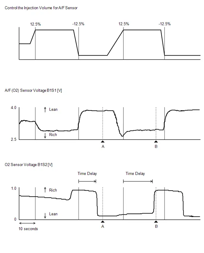
GTS Display
Measurement Item/Operation
Normal Condition
Control the Injection Volume for A/F Sensor
-
▲A
▲B
Active Test operation
-12.5%
12.5%
A/F (O2) Sensor Voltage B1S1
3.724 V
2.397 V
O2 Sensor Voltage B1S2
0.055 V
0.955 V
HINT:
- While performing the Active Test, air fuel ratio feedback control and feedback learning are stopped.
- Usually, the value of A/F (O2) Sensor Voltage B1S1 drops below 3.1 V when the control value for Control the Injection Volume for A/F Sensor is changed to 12.5%.
- Usually, the value of A/F (O2) Sensor Voltage B1S1 changes to 3.4 V or higher when the control value for Control the Injection Volume for A/F Sensor is changed to -12.5%.
- Usually, the value of O2 Sensor Voltage B1S2 changes to 0.55 V or higher when the control value for Control the Injection Volume for A/F Sensor is changed to 12.5%.
- Usually, the value of O2 Sensor Voltage B1S2 drops below 0.4 V when the control value for Control the Injection Volume for A/F Sensor is changed to -12.5%.
- The air fuel ratio sensor has an output delay of a few seconds and the heated oxygen sensor has a maximum output delay of approximately 20 seconds.
- If the sensor output voltage does not change (almost no reaction) while performing the Active Test, the sensor may be malfunctioning.
-
*4: Control the ETCS Open/Close Fast Speed [Active Test for electrical throttle control system] (Ignition switch ON, Accelerator pedal fully depressed)
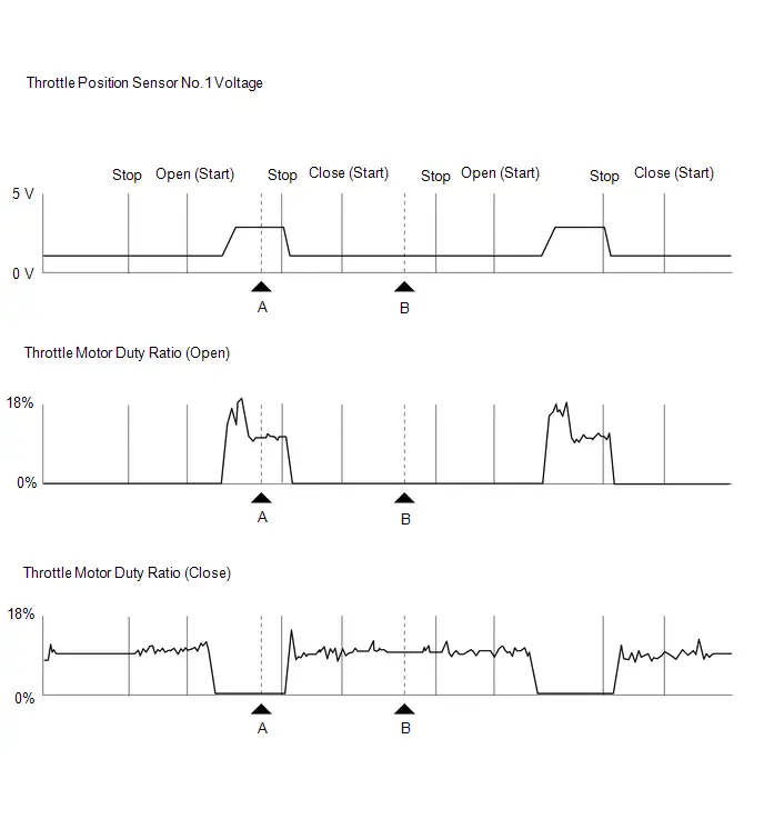
GTS Display
Measurement Item/Operation
Normal Condition
Control the ETCS Open/Close Fast Speed
-
▲A
▲B
Active Test operation
Open
Close
Throttle Position Sensor No.1 Voltage
2.597 V
0.742 V
Throttle Motor Duty Ratio (Open)
13.0%
0.0%
Throttle Motor Duty Ratio (Close)
0.0%
13.0%
HINT:
If any DTCs related to the Electronic Throttle Control System (ETCS) are stored, this Active Test cannot be performed.
-
*5: Activate the EVAP Purge VSV (Engine warmed up and idling, inspection mode [maintenance mode], not charge control)
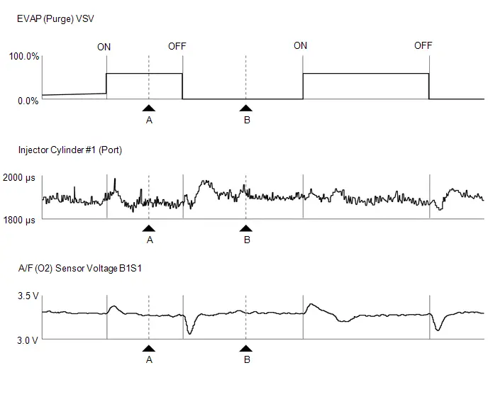
GTS Display
Measurement Item/Operation
Normal Condition
Activate the EVAP Purge VSV
-
▲A
▲B
Active Test operation
ON
OFF
EVAP (Purge) VSV
49.8%
0.0%
Injector Cylinder #1 (Port)
1859 μs
1894 μs
A/F (O2) Sensor Voltage B1S1
3.296 V
3.301 V
HINT:
- The graphs and values above are for reference only because the fuel injection volume (compensation volume) varies depending on the HC density of the purge air from the canister.
- Even when the Active Test is performed (the purge VSV is opened approximately 50%), the ECM performs air fuel ratio feedback to maintain the air fuel ratio at the stoichiometric ratio. Therefore, by observing the change in the Data List item "Injector Cylinder #1 (Port)", it is possible to determine whether the purge VSV is actually open.
-
*6: Control the EGR Step Position (Engine warmed up and idling, inspection mode [maintenance mode], not charge control)
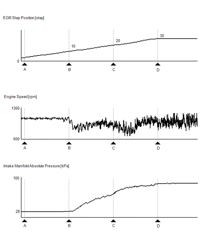
GTS Display
Measurement Item/Operation
Normal Condition
Control the EGR Step Position
-
▲A
▲B
▲C
▲D
EGR Step Position
0 step
10 step
20 step
30 step
Intake Manifold Absolute Pressure
28 kPa (4.06 psi)
28 kPa (4.06 psi)
67 kPa (9.72 psi)
88 kPa (12.76 psi)
NOTICE:
- Make sure that the value of Data List item Engine Independent is "Operate" while performing the Active Test.
- Do not leave the EGR valve open for 10 seconds or more while performing Active Test.
- Be sure to return the EGR valve to step 0 when the Active Test is completed.
- Do not open the EGR valve 30 steps or more during the Active Test.
HINT:
- When the value of Control the EGR Step Position is "0 step", the value of Intake Manifold Absolute Pressure should be between 20 and 40 kPa (2.9 to 5.8 psi).
- When the EGR system is normal and the value of Control the EGR Step Position is changed from "0 step" to "30 step", the value of Intake Manifold Absolute Pressure will increase to a value at least 10 kPa (1.45 psi) higher than the value of Intake Manifold Absolute Pressure when the value of Control the EGR Step Position was "0 step".
- If the value of Data List item Engine Independent is "Not Opr" when the engine is idling, charge control is being performed. Perform the Active Test after charge control is complete ("Operate" is displayed).
-
*7: Control the Intake VVT OCV Duty Ratio Bank 1 (Idling, inspection mode [maintenance mode], not charge control)
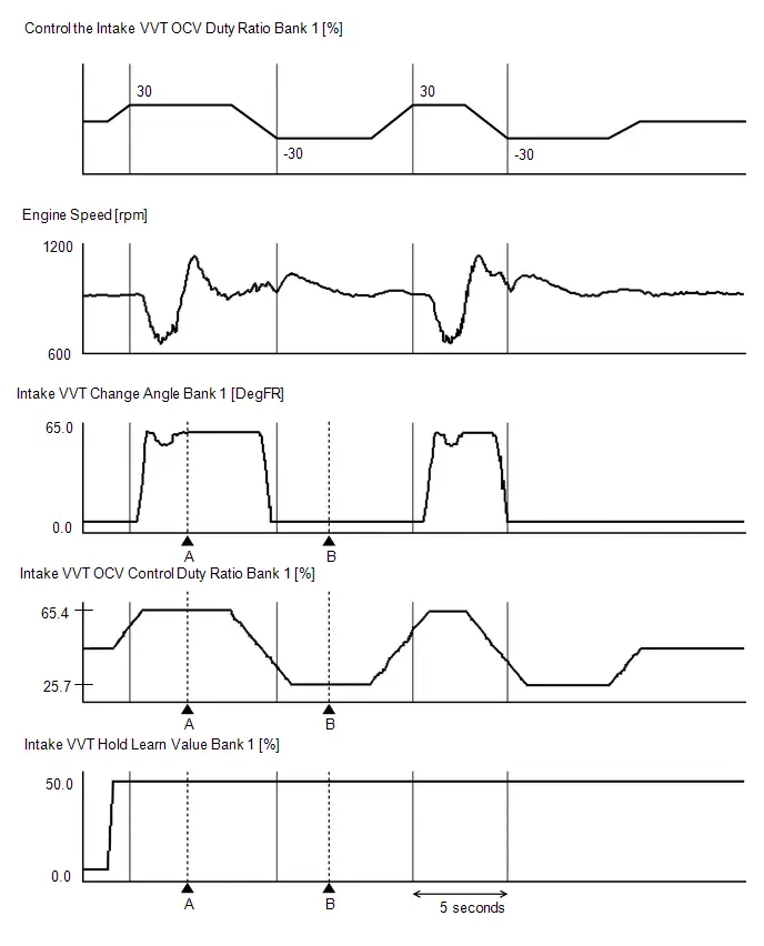
GTS Display
Measurement Item/Operation
Normal Condition
Control the Intake VVT OCV Duty Ratio Bank 1
-
▲A
▲B
Active Test operation*
30%
-30%
Intake VVT Change Angle Bank 1
62.5 DegFR
0.0 DegFR
Intake VVT OCV Control Duty Ratio Bank 1
65.4%
25.7%
Intake VVT Hold Learn Value Bank 1
50.0%
50.0%
HINT:
- *: Change the control value for Control the Intake VVT OCV Duty Ratio Bank 1 to 30% or -30%.
- Test not possible with park (P) selected during charge control. Select neutral (N) to perform test.
Vehicle Control History
VEHICLE CONTROL HISTORY
DESCRIPTION (SFI SYSTEM)
- Vehicle Control History is a function that captures and stores ECU data when triggered by specific vehicle behavior.
- If the customer states that the engine stalled or will not start, it may be possible to diagnose the cause of the malfunction by checking the Toyota Prius vehicle history information and freeze frame data.
- The number of possible stored Freeze Frame Data sets, whether multi Freeze Frame Data is available, the number of freeze frame points, Freeze Frame Data items, the ECU internal range, etc., is different depending on the stored group.
-
The stored data items for Toyota Prius Vehicle Control History Freeze Frame Data are different depending on the stored group. When the value of a data item does not change across all points, only the value of the detection point will be displayed. The contents of the Freeze Frame Data is almost the same as that of the Data List.
Click here

PRECAUTIONS (SFI SYSTEM)
- As Toyota Prius Vehicle Control History may be overwritten whenever the trigger conditions are met, make sure to save Vehicle Control History before performing any inspections.
- As Vehicle Control History may be stored when performing an Active Test, learning, etc., make sure to clear the Vehicle Control History before returning the Toyota Prius vehicle to the customer.
CHECK VEHICLE CONTROL HISTORY (SFI SYSTEM)
HINT:
- Vehicle control history (SFI system) is stored when Switch Specification Information learning is incomplete.
- Perform Switch Specification Information after replacing the ECM.
(a) Enter the following menus: Powertrain / Engine / Utility / Toyota Prius Vehicle Control History (RoB).
Powertrain > Engine > Utility| Tester Display |
|---|
| Vehicle Control History (RoB) |
HINT:
It is also possible to display Toyota Prius Vehicle Control History during the Health Check, if "Store All Data" is selected.
Vehicle Control History Item| Code | Item | Trigger Description | Stored Group | Reference Inspection Procedure | Link |
|---|---|---|---|---|---|
| XF01B | ECU Security Key Not Registered | ECU security key not updated | - | - |
|

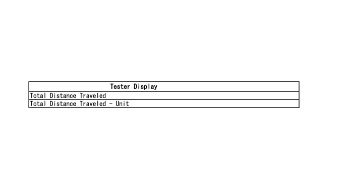
CLEAR VEHICLE CONTROL HISTORY (SFI SYSTEM)
(a) Enter the following menus: Powertrain / Engine / Utility / Vehicle Control History (RoB) (Clear).
NOTICE:
By performing this procedure, all stored Toyota Prius Vehicle Control History items will be cleared.
Powertrain > Engine > Utility| Tester Display |
|---|
| Vehicle Control History (RoB) |
VEHICLE CONTROL HISTORY (AIRBAG SYSTEM)
HINT:
A part of the control history can be confirmed using the Toyota Prius vehicle control history.
Click here

VEHICLE CONTROL HISTORY (HYBRID CONTROL SYSTEM)
HINT:
A part of the control history can be confirmed using the vehicle control history.
Click here

A Camshaft Position Actuator Bank 1 Circuit Open (P001013)
DESCRIPTION
The Variable Valve Timing (VVT) system consists of the ECM, camshaft timing oil control valve assembly and camshaft timing gear assembly.
The VVT system controls the camshaft timing oil control valve assembly to operate the camshaft timing gear assembly and optimize the intake valve timing according to driving conditions. This control is performed based on the air flow volume, throttle position, engine coolant temperature, etc. Based on signals from each sensor, the ECM controls the position of the camshaft timing control valve assembly to change the relative position of the camshaft, enhance the engine torque and fuel economy and decrease the exhaust gas emissions. Using signals from the camshaft position sensor, the ECM detects the actual valve timing and performs feedback control to optimize the valve timing.
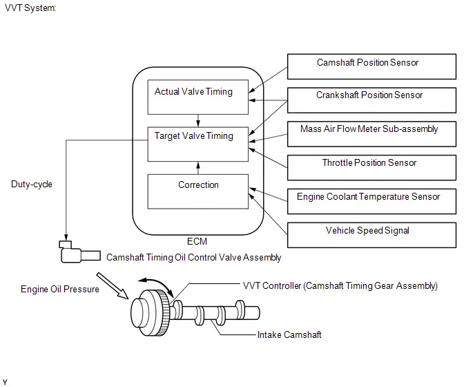
| DTC No. | Detection Item | DTC Detection Condition | Trouble Area | MIL | DTC Output from | Priority | Note |
|---|---|---|---|---|---|---|---|
| P001013 | A Camshaft Position Actuator Bank 1 Circuit Open | Open or short in camshaft timing oil control valve assembly circuit (1 trip detection logic). |
| Comes on | Engine | A | SAE Code: P0010 |
MONITOR DESCRIPTION
This DTC is designed to detect an open or short in the camshaft timing oil control valve assembly circuit. If the camshaft timing oil control valve assembly duty-cycle is excessively high or low while the ignition switch is ON or the engine is running, the ECM will illuminate the MIL and store this DTC.
CONFIRMATION DRIVING PATTERN
- Clear the DTCs (even if no DTCs are stored, perform the clear DTC procedure).
- Turn the ignition switch off and wait for at least 30 seconds.
- Turn the ignition switch ON.
- Wait 5 seconds or more.
- Enter the following menus: Powertrain / Engine / Trouble Codes.
-
Read the pending DTCs.
HINT:
- If a pending DTC is output, the system is malfunctioning.
- If a pending DTC is not output, perform the following procedure.
- Enter the following menus: Powertrain / Engine / Utility / All Readiness.
- Input the DTC: P001013.
-
Check the DTC judgment result.
HINT:
- If the judgment result is NORMAL, the system is normal.
- If the judgment result is ABNORMAL, the system is malfunctioning.
- If the judgment result is INCOMPLETE, perform the Confirmation Driving Pattern and check the DTC judgment result again.
WIRING DIAGRAM
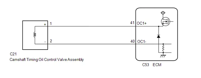
CAUTION / NOTICE / HINT
NOTICE:
-
Toyota Prius Vehicle Control History may be stored in the hybrid vehicle control ECU assembly if the engine is malfunctioning. Certain vehicle condition information is recorded when Vehicle Control History is stored. Reading the vehicle conditions recorded in both the freeze frame data and Vehicle Control History can be useful for troubleshooting.
Click here

(Select Powertrain in Health Check and then check the time stamp data.)
-
If any "Engine Malfunction" Toyota Prius Vehicle Control History item has been stored in the hybrid vehicle control ECU assembly, make sure to clear it. However, as all Vehicle Control History items are cleared simultaneously, if any Vehicle Control History items other than "Engine Malfunction" are stored, make sure to perform any troubleshooting for them before clearing Toyota Prius Vehicle Control History.
Click here

PROCEDURE
| 1. | CLEAR DTC |
Pre-procedure1
(a) None
Procedure1
(b) Clear the DTC after recording the freeze frame data and DTC.
Powertrain > Engine > Clear DTCsPost-procedure1
(c) Turn the ignition switch off and wait for at least 30 seconds.
|

| 2. | READ OUTPUT DTC (DTC P001013) |
Pre-procedure1
(a) Put the engine in Inspection Mode (Maintenance Mode).
Powertrain > Hybrid Control > Utility| Tester Display |
|---|
| Inspection Mode |
(b) Start the engine.
Procedure1
(c) Read the DTCs.
Powertrain > Engine > Trouble Codes| Result | Proceed to |
|---|---|
| DTCs are not output | A |
| P001013 is output | B |
Post-procedure1
(d) None
| A |

| CHECK FOR INTERMITTENT PROBLEMS |
|

| 3. | INSPECT CAMSHAFT TIMING OIL CONTROL VALVE ASSEMBLY |
Click here

| NG |

| REPLACE CAMSHAFT TIMING OIL CONTROL VALVE ASSEMBLY |
|

| 4. | CHECK HARNESS AND CONNECTOR (CAMSHAFT TIMING OIL CONTROL VALVE ASSEMBLY - ECM) |
Pre-procedure1
(a) Disconnect the camshaft timing oil control valve assembly connector.
(b) Disconnect the ECM connector.
Procedure1
(c) Measure the resistance according to the value(s) in the table below.
Standard Resistance:
 Click Location & Routing(C21,C53) Click Connector(C21) Click Connector(C53)
 | Tester Connection | Condition | Specified Condition | Result |
|---|---|---|---|
| C21-1 ( ) - C53-41 (OC1 ) | Always | Below 1 Ω | Ω |
| C21-2 (-) - C53-40 (OC1-) | Always | Below 1 Ω | Ω |
| C21-1 ( ) or C53-41 (OC1 ) - Body ground and other terminals | Always | 10 kΩ or higher | kΩ |
| C21-2 (-) or C53-40 (OC1-) - Body ground and other terminals | Always | 10 kΩ or higher | kΩ |
Post-procedure1
(d) None
| OK |

| REPLACE ECM |
| NG |

| REPAIR OR REPLACE HARNESS OR CONNECTOR |
Camshaft Position "A" - Timing Over-Advanced or System Performance Bank 1 (P001100,P001200)
DESCRIPTION
Refer to DTC P001013.
Click here

| DTC No. | Detection Item | DTC Detection Condition | Trouble Area | MIL | DTC Output from | Priority | Note |
|---|---|---|---|---|---|---|---|
| P001100 | Camshaft Position "A" - Timing Over-Advanced or System Performance Bank 1 | Intake valve timing is stuck at a certain value when in the advance range (1 trip detection logic). |
| Comes on | Engine | B | SAE Code: P0011 |
| P001200 | Camshaft Position "A" - Timing Over-Retarded Bank 1 | Intake valve timing is stuck at a certain value when in the retard range (2 trip detection logic). |
| Comes on | Engine | B | SAE Code: P0012 |
MONITOR DESCRIPTION
The ECM optimizes the intake valve timing using the Variable Valve Timing (VVT) system to control the intake camshaft. The VVT system includes the ECM, camshaft timing oil control valve assembly and VVT controller (camshaft timing gear assembly). The ECM sends a target duty-cycle control signal to the camshaft timing oil control valve assembly. This control signal regulates the oil pressure supplied to the VVT controller. The VVT controller can advance or retard the intake camshaft.
If the difference between the target and actual intake valve timing is large, and changes in the actual intake valve timing are small, the ECM interprets this as a VVT controller stuck malfunction and stores a DTC.
- Example:
-
A DTC is stored when the following conditions are met:
- It takes 5 seconds or more to change the valve timing by 5°CA.
- After the above condition is met, the camshaft timing oil control valve assembly is forcibly activated for 9.5 seconds or more.
DTC P001100 (Advanced Camshaft Timing) is subject to 1 trip detection logic.
DTC P001200 (Retarded Camshaft Timing) is subject to 2 trip detection logic.
These DTCs indicate that the VVT controller cannot operate properly due to a camshaft timing oil control valve assembly malfunction or the presence of foreign matter in the camshaft timing oil control valve assembly.
MONITOR STRATEGY
| Required Sensors/Components (Main) | Camshaft timing oil control valve assembly Camshaft timing gear assembly |
| Required Sensors/Components (Related) | Crankshaft position sensor Camshaft position sensor Engine coolant temperature sensor |
| Frequency of Operation | Continuous |
CONFIRMATION DRIVING PATTERN
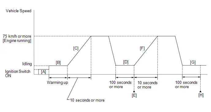
-
Clear the DTCs (even if no DTCs are stored, perform the clear DTC procedure).
HINT:
-
If P001100 was output:
Clear the DTC without using the GTS.
-
If P001200 was output:
Clear the DTC using the GTS.
-
If P001100 was output:
- Turn the ignition switch off and wait for at least 30 seconds.
- Turn the ignition switch ON [A].
-
Put the engine in Inspection Mode (Maintenance Mode).
Click here

- Start the engine and warm it up until the engine coolant temperature is 75°C (167°F) or higher [B].
-
With the engine running, accelerate the Toyota Prius vehicle to 75 km/h (46 mph) or more by depressing the accelerator pedal for 10 seconds or more [C].
CAUTION:
When performing the confirmation driving pattern, obey all speed limits and traffic laws.
HINT:
If the engine stops, further depress the accelerator pedal to restart the engine.
- Idle the engine for 100 seconds or more [D].
- Enter the following menus: Powertrain / Engine / Trouble Codes [E].
-
Read the pending DTCs.
HINT:
- If a pending DTC is output, the system is malfunctioning.
- If a pending DTC is not output, perform the following procedure.
- Enter the following menus: Powertrain / Engine / Utility / All Readiness.
- Input the DTC: P001100 or P001200.
-
Check the DTC judgment result.
HINT:
- If the judgment result is NORMAL, the system is normal.
- If the judgment result is ABNORMAL, the system is malfunctioning.
- If the judgment result is INCOMPLETE, perform steps [F] through [H].
-
With the engine running, accelerate the Toyota Prius vehicle to 75 km/h (46 mph) or more by depressing the accelerator pedal for 10 seconds or more [F].
CAUTION:
When performing the confirmation driving pattern, obey all speed limits and traffic laws.
HINT:
If the engine stops, further depress the accelerator pedal to restart the engine.
- Idle the engine for 100 seconds or more [G].
- Enter the following menus: Powertrain / Engine / Trouble Codes [H].
-
Read the pending DTCs.
HINT:
- If a pending DTC is output, the system is malfunctioning.
- If a pending DTCs are not output, perform the following procedure.
-
Check the DTC judgment result again.
HINT:
- If the judgment result is NORMAL, the system is normal.
- If the judgment result is ABNORMAL, the system is malfunctioning.
WIRING DIAGRAM
Refer to DTC P001013.
Click here

CAUTION / NOTICE / HINT
NOTICE:
-
Toyota Prius Vehicle Control History may be stored in the hybrid vehicle control ECU assembly if the engine is malfunctioning. Certain vehicle condition information is recorded when Vehicle Control History is stored. Reading the vehicle conditions recorded in both the freeze frame data and Vehicle Control History can be useful for troubleshooting.
Click here

(Select Powertrain in Health Check and then check the time stamp data.)
-
If any "Engine Malfunction" Toyota Prius Vehicle Control History item has been stored in the hybrid vehicle control ECU assembly, make sure to clear it. However, as all Vehicle Control History items are cleared simultaneously, if any Vehicle Control History items other than "Engine Malfunction" are stored, make sure to perform any troubleshooting for them before clearing Toyota Prius Vehicle Control History.
Click here

HINT:
DTC P001100 or P001200 may be stored when foreign matter in the engine oil is caught in parts of the system. The DTC will remain stored even if the system returns to normal after a short time. The foreign matter may then be captured by the oil filter.
PROCEDURE
| 1. | CHECK ANY OTHER DTCS OUTPUT (IN ADDITION TO DTC P001100 OR P001200) |
(a) Read the DTCs.
Powertrain > Engine > Trouble Codes| Result | Proceed to |
|---|---|
| P001100 or P001200 and other DTCs are output | A |
| P001100 or P001200 is output | B |
HINT:
If any DTCs other than P001100 or P001200 are output, troubleshoot those DTCs first.
| A |

| GO TO DTC CHART |
|

| 2. | PERFORM ACTIVE TEST USING GTS (CONTROL THE INTAKE VVT OCV DUTY RATIO BANK 1) |
Pre-procedure1
(a) Put the engine in Inspection Mode (Maintenance Mode).
Powertrain > Hybrid Control > Utility| Tester Display |
|---|
| Inspection Mode |
(b) Start the engine.
Procedure1
(c) Check the engine speed while operating the camshaft timing oil control valve assembly using the GTS.
Powertrain > Engine > Active Test| Tester Display |
|---|
| Control the Intake VVT OCV Duty Ratio Bank 1 |
OK:
| GTS Operation | Specified Condition |
|---|---|
| 0% | Normal engine speed |
| 100% | Engine idles roughly or stalls |
HINT:
- Test not possible with park (P) selected during charge control. Select neutral (N) to perform test.
- If DTCs are stored after the Active Test, clear the DTCs.
Post-procedure1
(d) None
| NG |

| GO TO STEP 5 |
|

| 3. | CLEAR DTC |
Pre-procedure1
(a) None
Procedure1
(b) Clear the DTCs.
Powertrain > Engine > Clear DTCsHINT:
-
If P001100 was output:
Clear the DTC without using the GTS.
-
If P001200 was output:
Clear the DTC using the GTS.
Post-procedure1
(c) Turn the ignition switch off and wait for at least 30 seconds.
|

| 4. | CHECK WHETHER DTC OUTPUT RECURS (DTC P001100 OR P001200) |
Pre-procedure1
(a) Drive the Toyota Prius vehicle in accordance with the driving pattern described in Confirmation Driving Pattern.
Procedure1
(b) Read the DTCs.
Powertrain > Engine > Trouble Codes| Result | Proceed to |
|---|---|
| DTCs are not output | A |
| P001100 or P001200 is output | B |
HINT:
DTC P001100 or P001200 may be stored when foreign matter in the engine oil is caught in parts of the system. The DTC will remain stored even if the system returns to normal after a short time. The foreign matter may then be captured by the oil filter.
Post-procedure1
(c) None
| A |

| CHECK FOR INTERMITTENT PROBLEMS |
| B |

| GO TO STEP 5 |
| 5. | INSPECT CAMSHAFT TIMING OIL CONTROL VALVE ASSEMBLY |
Click here

| NG |

| REPLACE CAMSHAFT TIMING OIL CONTROL VALVE ASSEMBLY |
|

| 6. | CHECK VALVE TIMING (CHECK FOR LOOSE TIMING CHAIN AND JUMPED TEETH) |
Pre-procedure1
(a) Remove the cylinder head cover sub-assembly.

| *a | 39.5° | *b | Timing Mark |
| *c | "0" Timing Mark | *d | Groove |
(b) Turn the crankshaft pulley and align its groove with the "0" timing mark of the timing chain or belt cover sub-assembly.
Procedure1
(c) Check that the timing marks of the camshaft timing gear assembly and camshaft timing sprocket are at the positions shown in the illustration.
HINT:
If the timing marks are not as shown, turn the crankshaft one revolution clockwise.
OK:
Timing marks on camshaft timing gear assembly and camshaft timing sprocket are at the positions shown in the illustration.
HINT:
If the result is not as specified, check for mechanical malfunctions that may have affected the valve timing, such as a jumped tooth or stretching of the timing chain.
Post-procedure1
(d) None
| NG |

| GO TO STEP 9 |
|

| 7. | INSPECT CAMSHAFT TIMING GEAR ASSEMBLY |
Click here

| NG |

| REPLACE CAMSHAFT TIMING GEAR ASSEMBLY |
|

| 8. | INSPECT OIL CONTROL VALVE FILTER |
Pre-procedure1
| (a) Remove the oil control valve filter. HINT: Click here
|
|


Procedure1
(b) Check that the filter is not clogged.
OK:
Filter is not clogged.
Post-procedure1
(c) None
| OK |

| GO TO STEP 10 |
| NG |

| REPLACE OIL CONTROL VALVE FILTER |
| 9. | CHECK ENGINE MECHANICAL SYSTEM |
(a) Check for mechanical malfunctions that affect the valve timing, such as a jumped tooth or stretching of the timing chain.
HINT:
Perform "Inspection After Repair" after repairing or replacing the engine mechanical system.
Click here

| NG |

| REPAIR OR REPLACE MALFUNCTIONING PARTS, COMPONENT AND AREA |
|

| 10. | CLEAR DTC |
Pre-procedure1
(a) None
Procedure1
(b) Clear the DTCs.
Powertrain > Engine > Clear DTCsHINT:
-
If P001100 was output:
Clear the DTC without using the GTS.
-
If P001200 was output:
Clear the DTC using the GTS.
Post-procedure1
(c) Turn the ignition switch off and wait for at least 30 seconds.
|

| 11. | CHECK WHETHER DTC OUTPUT RECURS (DTC P001100 OR P001200) |
Pre-procedure1
(a) Drive the Toyota Prius vehicle in accordance with the driving pattern described in Confirmation Driving Pattern.
Procedure1
(b) Read the DTCs.
Powertrain > Engine > Trouble Codes| Result | Proceed to |
|---|---|
| DTCs are not output | A |
| P001100 or P001200 is output | B |
Post-procedure1
(c) None
| A |

| CHECK FOR INTERMITTENT PROBLEMS |
| B |

| REPLACE ECM |
Crankshaft Position - Camshaft Position Correlation Bank 1 Sensor A (P001600)
DESCRIPTION
Refer to DTC P001013.
Click here

| DTC No. | Detection Item | DTC Detection Condition | Trouble Area | MIL | DTC Output from | Priority | Note |
|---|---|---|---|---|---|---|---|
| P001600 | Crankshaft Position - Camshaft Position Correlation Bank 1 Sensor A | Deviation in the crankshaft position sensor signal and camshaft position sensor signal (2 trip detection logic). |
| Comes on / Does not come on | Engine | B | SAE Code: P0016 |
MONITOR DESCRIPTION
To monitor the correlation of the intake camshaft position and crankshaft position, the ECM checks the VVT learned value while the engine is idling. The VVT learned value is calibrated based on the camshaft position and crankshaft position. The intake valve timing is set to the most retarded angle while the engine is idling. If the VVT learned value is out of the specified range in consecutive driving cycles, the ECM stores this DTC.
MONITOR STRATEGY
| Required Sensors/Components (Main) | Camshaft timing gear assembly |
| Required Sensors/Components (Related) | Camshaft position sensor Crankshaft position sensor |
| Frequency of Operation | Continuous |
TYPICAL ENABLING CONDITIONS
| Engine speed | 900 to 1100 rpm |
CONFIRMATION DRIVING PATTERN
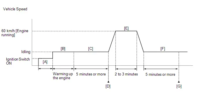
- Clear the DTCs (even if no DTCs are stored, perform the clear DTC procedure).
- Turn the ignition switch off and wait for at least 30 seconds.
- Turn the ignition switch ON [A].
-
Put the engine in Inspection Mode (Maintenance Mode).
Click here

- Start the engine and warm it up until the engine coolant temperature is 75°C (167°F) or higher [B].
- Idle the engine for 5 minutes or more [C].
- Enter the following menus: Powertrain / Engine / Trouble Codes [D].
-
Read the pending DTCs.
HINT:
- If a pending DTC is output, the system is malfunctioning.
- If a pending DTC is not output, perform the following procedure.
- Enter the following menus: Powertrain / Engine / Utility / All Readiness.
- Input the DTC: P001600.
-
Check the DTC judgment result.
HINT:
- If the judgment result is NORMAL, the system is normal.
- If the judgment result is ABNORMAL, the system is malfunctioning.
- If the judgment result is INCOMPLETE, perform steps [E] through [G].
-
With the engine running, drive the Toyota Prius vehicle at 60 km/h (37 mph) for 2 to 3 minutes [E].
CAUTION:
When performing the confirmation driving pattern, obey all speed limits and traffic laws.
HINT:
If the engine stops, further depress the accelerator pedal to restart the engine.
- Idle the engine for 5 minutes or more [F].
- Enter the following menus: Powertrain / Engine / Trouble Codes [G].
-
Read the pending DTCs.
HINT:
- If a pending DTC is output, the system is malfunctioning.
- If a pending DTC is not output, perform the following procedure.
-
Check the DTC judgment result.
HINT:
- If the judgment result is NORMAL, the system is normal.
- If the judgment result is ABNORMAL, the system is malfunctioning.
CAUTION / NOTICE / HINT
NOTICE:
-
Toyota Prius Vehicle Control History may be stored in the hybrid vehicle control ECU assembly if the engine is malfunctioning. Certain vehicle condition information is recorded when Vehicle Control History is stored. Reading the vehicle conditions recorded in both the freeze frame data and Vehicle Control History can be useful for troubleshooting.
Click here

(Select Powertrain in Health Check and then check the time stamp data.)
-
If any "Engine Malfunction" Toyota Prius Vehicle Control History item has been stored in the hybrid vehicle control ECU assembly, make sure to clear it. However, as all Vehicle Control History items are cleared simultaneously, if any Vehicle Control History items other than "Engine Malfunction" are stored, make sure to perform any troubleshooting for them before clearing Toyota Prius Vehicle Control History.
Click here

HINT:
The monitor for this DTC detects when the timing chain is shifted by one tooth or more.
PROCEDURE
| 1. | CHECK ANY OTHER DTCS OUTPUT (IN ADDITION TO DTC P001600) |
(a) Read the DTCs.
Powertrain > Engine > Trouble Codes| Result | Proceed to |
|---|---|
| P001600 and other DTCs are output | A |
| P001600 is output | B |
HINT:
If any DTCs other than P001600 are output, troubleshoot those DTCs first.
| A |

| GO TO DTC CHART |
|

| 2. | PERFORM ACTIVE TEST USING GTS (CONTROL THE INTAKE VVT OCV DUTY RATIO BANK 1) |
Pre-procedure1
HINT:
If the VVT system can be operated through the Active Test, it can be assumed that the VVT system is operating normally.
(a) Put the engine in Inspection Mode (Maintenance Mode).
Powertrain > Hybrid Control > Utility| Tester Display |
|---|
| Inspection Mode |
(b) Start the engine.
Procedure1
(c) Perform the Active Test according to the display on the GTS and check that the displacement angle changes.
Powertrain > Engine > Active Test| Active Test Display |
|---|
| Control the Intake VVT OCV Duty Ratio Bank 1 |
| Data List Display |
|---|
| Intake VVT Change Angle Bank 1 |
OK:
Displacement angle changes.
HINT:
- Test not possible with park (P) selected during charge control. Select neutral (N) to perform test.
- If DTCs are stored after the Active Test, clear the DTCs.
Post-procedure1
(d) None
| NG |

| GO TO STEP 4 |
|

| 3. | CHECK ENGINE MECHANICAL SYSTEM |
(a) Check for mechanical malfunctions that affect the valve timing, such as a jumped tooth or stretching of the timing chain.
HINT:
Perform "Inspection After Repair" after repairing or replacing the engine mechanical system.
Click here

| OK |

| GO TO STEP 7 |
| NG |

| REPAIR OR REPLACE MALFUNCTIONING PARTS, COMPONENT AND AREA |
| 4. | INSPECT CAMSHAFT TIMING OIL CONTROL VALVE ASSEMBLY |
Click here

| NG |

| REPLACE CAMSHAFT TIMING OIL CONTROL VALVE ASSEMBLY |
|

| 5. | INSPECT CAMSHAFT TIMING GEAR ASSEMBLY |
Click here

| NG |

| REPLACE CAMSHAFT TIMING GEAR ASSEMBLY |
|

| 6. | INSPECT OIL CONTROL VALVE FILTER |
Pre-procedure1
| (a) Remove the oil control valve filter. HINT: Click here
|
|

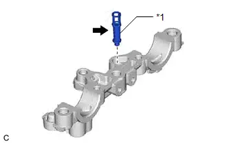
Procedure1
(b) Check that the filter is not clogged.
OK:
Filter is not clogged.
Post-procedure1
(c) None
| NG |

| REPLACE OIL CONTROL VALVE FILTER |
|

| 7. | CLEAR DTC |
Pre-procedure1
(a) None
Procedure1
(b) Clear the DTCs.
Powertrain > Engine > Clear DTCsPost-procedure1
(c) Turn the ignition switch off and wait for at least 30 seconds.
|

| 8. | CHECK WHETHER DTC OUTPUT RECURS (DTC P001600) |
Pre-procedure1
(a) Drive the Toyota Prius vehicle in accordance with the driving pattern described in Confirmation Driving Pattern.
Procedure1
(b) Read the pending DTCs.
Powertrain > Engine > Trouble Codes| Result | Proceed to |
|---|---|
| DTCs are not output | A |
| P001600 is output | B |
Post-procedure1
(c) None
| A |

| CHECK FOR INTERMITTENT PROBLEMS |
| B |

| REPLACE ECM |
HO2S Heater Control Bank 1 Sensor 1 Circuit Short to Battery (P003012,P003013,P101A9E)
DESCRIPTION
The air fuel ratio sensor generates voltage* that corresponds to the actual air fuel ratio. This sensor voltage is used to provide the ECM with feedback so that it can control the air fuel ratio. The ECM determines the deviation from the stoichiometric air fuel ratio, and regulates the fuel injection time. If the air fuel ratio sensor malfunctions, the ECM is unable to control the air fuel ratio accurately.
The air fuel ratio sensor is a planar type and integrated with a heater, which heats the solid electrolyte (zirconia element). This heater is controlled by the ECM. When the intake air volume is low (the exhaust gas temperature is low), current flows to the heater to heat the sensor, in order to facilitate accurate oxygen concentration detection. In addition, the sensor and heater portions are a narrow type. The heat generated by the heater is conducted to the solid electrolyte through alumina, therefore sensor activation is accelerated.
In order to obtain a high purification rate of the carbon monoxide (CO), hydrocarbon (HC) and nitrogen oxide (NOx) components in the exhaust gas, a three-way catalytic converter is used. For the most efficient use of the three-way catalytic converter, the air fuel ratio must be precisely controlled so that it is always close to the stoichiometric air fuel ratio.
*: Value changes inside the ECM. Since the air fuel ratio sensor is a current output element, the current is converted into a voltage inside the ECM. Any measurements taken at the air fuel ratio sensor or ECM connectors will show a constant voltage.
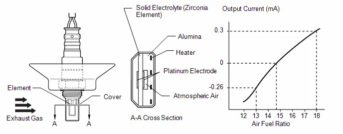
HINT:
- Although the DTC titles say oxygen sensor, these DTCs relate to the air fuel ratio sensor.
- When any of these DTCs are stored, the ECM enters fail-safe mode. The ECM turns off the air fuel ratio sensor heater in fail-safe mode. Fail-safe mode continues until the ignition switch is turned off.
-
The ECM has a pulse width modulated control circuit to adjust the current through the heater. The air fuel ratio sensor heater circuit uses a relay on the B side of the circuit.
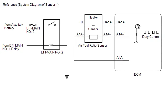
| DTC No. | Detection Item | DTC Detection Condition | Trouble Area | MIL | DTC Output from | Priority | Note |
|---|---|---|---|---|---|---|---|
| P003012 | HO2S Heater Control Bank 1 Sensor 1 Circuit Short to Battery | The air fuel ratio sensor heater current is more than the specified value while the heater is operating (1 trip detection logic). |
| Comes on | Engine | A | SAE Code: P0032 |
| P003013 | HO2S Heater Control Bank 1 Sensor 1 Circuit Open | The air fuel ratio sensor heater current is less than the specified value while the heater is operating (1 trip detection logic). |
| Comes on | Engine | A | SAE Code: P0031 |
| P101A9E | A/F Sensor Heater Performance Bank 1 Sensor 1 Stuck On | The air fuel ratio sensor heater voltage level is low while the heater is not operating (1 trip detection logic). |
| Comes on | Engine | A | SAE Code: P101D |
MONITOR DESCRIPTION
The ECM uses information from the air fuel ratio sensor to regulate the air fuel ratio and keep it close to the stoichiometric level. This maximizes the ability of the three-way catalytic converter to purify the exhaust gases.
The air fuel ratio sensor detects oxygen levels in the exhaust gas and transmits the information to the ECM. The inner surface of the sensor element is exposed to the outside air. The outer surface of the sensor element is exposed to the exhaust gas. The sensor element is made of platinum-coated zirconia and includes an integrated heating element.
The zirconia element generates a small voltage when there is a large difference in the oxygen concentrations between the exhaust gas and outside air. The platinum coating amplifies this voltage generation.
The air fuel ratio sensor is more efficient when heated. When the exhaust gas temperature is low, the sensor cannot generate a useful current signals without supplementary heating. The ECM regulates the supplementary heating using a duty-cycle approach to adjust the average current in the sensor heater element. If the heater current is outside the normal range, the signal transmitted by the air fuel ratio sensor becomes inaccurate. As a result, the ECM is unable to regulate the air fuel ratio properly.
When the current in the air fuel ratio sensor heater is outside the normal operating range, the ECM interprets this as a malfunction in the sensor heater and stores a DTC.
MONITOR STRATEGY
| Required Sensors/Components | Air fuel ratio sensor (sensor 1) heater |
| Frequency of Operation | Continuous |
TYPICAL ENABLING CONDITIONS
P003012| Output duty cycle | 7% or higher |
| Output duty cycle | 7% or higher |
| Output duty cycle | Less than 75% |
CONFIRMATION DRIVING PATTERN
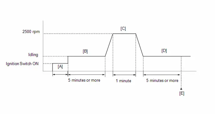
- Clear the DTCs (even if no DTCs are stored, perform the clear DTC procedure).
- Turn the ignition switch off and wait for at least 30 seconds.
- Turn the ignition switch ON [A].
-
Put the engine in Inspection Mode (Maintenance Mode).
Click here

- Start the engine and idle it for 5 minutes or more [B].
-
With the Toyota Prius vehicle stationary, depress the accelerator pedal and maintain an engine speed of 2500 rpm for 1 minute [C].
HINT:
During charge control, the engine speed is set at idle. Therefore, the engine speed will not increase when the accelerator pedal is depressed. In this case, perform steps [C] and [D] after charge control has completed.
- Idle the engine for 5 minutes or more [D].
- Enter the following menus: Powertrain / Engine / Trouble Codes [E].
-
Read the pending DTCs.
HINT:
- If a pending DTC is output, the system is malfunctioning.
- If a pending DTC is not output, perform the following procedure.
- Enter the following menus: Powertrain / Engine / Utility / All Readiness.
- Input the DTC: P003012, P003013 or P101A9E.
-
Check the DTC judgment result.
HINT:
- If the judgment result is NORMAL, the system is normal.
- If the judgment result is ABNORMAL, the system is malfunctioning.
- If the judgment result is INCOMPLETE, perform steps [B] through [E] again.
WIRING DIAGRAM
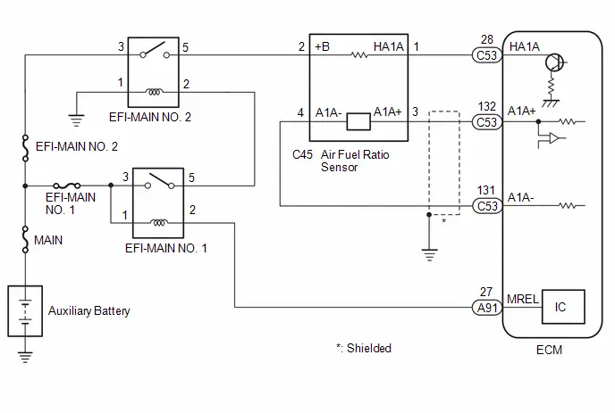
CAUTION / NOTICE / HINT
NOTICE:
- Inspect the fuses for circuits related to this system before performing the following procedure.
-
Toyota Prius Vehicle Control History may be stored in the hybrid vehicle control ECU assembly if the engine is malfunctioning. Certain vehicle condition information is recorded when Vehicle Control History is stored. Reading the vehicle conditions recorded in both the freeze frame data and Vehicle Control History can be useful for troubleshooting.
Click here

(Select Powertrain in Health Check and then check the time stamp data.)
-
If any "Engine Malfunction" Toyota Prius Vehicle Control History item has been stored in the hybrid vehicle control ECU assembly, make sure to clear it. However, as all Vehicle Control History items are cleared simultaneously, if any Vehicle Control History items other than "Engine Malfunction" are stored, make sure to perform any troubleshooting for them before clearing Toyota Prius Vehicle Control History.
Click here

HINT:
-
The operation of the air fuel ratio sensor heater can be checked by referring to the Data List item A/F (O2) Sensor Heater Duty Ratio B1S1.
Click here

- Sensor 1 refers to the sensor closest to the engine assembly.
- Sensor 2 refers to the sensor farthest away from the engine assembly.
-
Change the fuel injection volume using the Active Test "Control the Injection Volume for A/F Sensor" and monitor the air fuel ratio sensor output voltage (Click here
 ). If the air fuel ratio sensor output voltage does not change (almost no reaction) while performing the Active Test, the air fuel ratio sensor may be malfunctioning.
PROCEDURE
| 1. | INSPECT AIR FUEL RATIO SENSOR (HEATER RESISTANCE) |
Click here

| NG |

| REPLACE AIR FUEL RATIO SENSOR |
|

| 2. | CHECK TERMINAL VOLTAGE (POWER SOURCE OF AIR FUEL RATIO SENSOR) |
Pre-procedure1
(a) Disconnect the air fuel ratio sensor connector.
(b) Turn the ignition switch ON.
Procedure1
(c) Measure the voltage according to the value(s) in the table below.
Standard Voltage:
 Click Location & Routing(C45) Click Connector(C45)
 | Tester Connection | Condition | Specified Condition | Result |
|---|---|---|---|
| C45-2 ( B) - Body ground | Ignition switch ON | 11 to 14 V | V |
Post-procedure1
(d) None
| NG |

| GO TO STEP 6 |
|

| 3. | CHECK HARNESS AND CONNECTOR (AIR FUEL RATIO SENSOR - ECM) |
Pre-procedure1
(a) Disconnect the air fuel ratio sensor connector.
(b) Disconnect the ECM connector.
Procedure1
(c) Measure the resistance according to the value(s) in the table below.
Standard Resistance:
 Click Location & Routing(C45,C53) Click Connector(C45) Click Connector(C53)
 | Tester Connection | Condition | Specified Condition | Result |
|---|---|---|---|
| C45-1 (HA1A) - C53-28 (HA1A) | Always | Below 1 Ω | Ω |
| C45-1 (HA1A) or C53-28 (HA1A) - Body ground and other terminals | Always | 10 kΩ or higher | kΩ |
Post-procedure1
(d) None
| NG |

| REPAIR OR REPLACE HARNESS OR CONNECTOR |
|

| 4. | CLEAR DTC |
Pre-procedure1
(a) Clear the DTCs.
Powertrain > Engine > Clear DTCsProcedure1
(b) Turn the ignition switch off and wait for at least 30 seconds.
Post-procedure1
(c) None
|

| 5. | CHECK WHETHER DTC OUTPUT RECURS (DTC P003012, P003013 OR P101A9E) |
Pre-procedure1
(a) Drive the Toyota Prius vehicle in accordance with the driving pattern described in Confirmation Driving Pattern.
Procedure1
(b) Read the DTCs.
Powertrain > Engine > Trouble Codes| Result | Proceed to |
|---|---|
| DTCs are not output | A |
| P003012, P003013 or P101A9E is output | B |
Post-procedure1
(c) None
| A |

| CHECK FOR INTERMITTENT PROBLEMS |
| B |

| REPLACE ECM |
| 6. | INSPECT EFI-MAIN NO. 2 RELAY |
Click here

| NG |

| REPLACE EFI-MAIN NO. 2 RELAY |
|

| 7. | CHECK TERMINAL VOLTAGE (POWER SOURCE OF EFI-MAIN NO. 2 RELAY) |
Pre-procedure1
(a) Remove the EFI-MAIN NO. 2 relay from the No. 1 engine room relay block and No. 1 junction block assembly.
Procedure1
(b) Measure the voltage according to the value(s) in the table below.
Standard Voltage:
| Tester Connection | Condition | Specified Condition | Result |
|---|---|---|---|
| 3 (EFI-MAIN NO. 2 relay) - Body ground | Always | 11 to 14 V | V |
Post-procedure1
(c) None
| NG |

| REPAIR OR REPLACE HARNESS OR CONNECTOR (AUXILIARY BATTERY - EFI-MAIN NO. 2 RELAY) |
|

| 8. | CHECK HARNESS AND CONNECTOR (EFI-MAIN NO. 2 RELAY - BODY GROUND) |
Pre-procedure1
(a) Remove the EFI-MAIN NO. 2 relay from the No. 1 engine room relay block and No. 1 junction block assembly.
Procedure1
(b) Measure the resistance according to the value(s) in the table below.
Standard Resistance:
| Tester Connection | Condition | Specified Condition | Result |
|---|---|---|---|
| 1 (EFI-MAIN NO. 2 relay) - Body ground | Always | Below 1 Ω | Ω |
Post-procedure1
(c) None
| NG |

| REPAIR OR REPLACE HARNESS OR CONNECTOR |
|

| 9. | CHECK HARNESS AND CONNECTOR (EFI-MAIN NO. 2 RELAY - AIR FUEL RATIO SENSOR) |
Pre-procedure1
(a) Remove the EFI-MAIN NO. 2 relay from the No. 1 engine room relay block and No. 1 junction block assembly.
(b) Disconnect the air fuel ratio sensor connector.
Procedure1
(c) Measure the resistance according to the value(s) in the table below.
Standard Resistance:
 Click Location & Routing(C45) Click Connector(C45)
 | Tester Connection | Condition | Specified Condition | Result |
|---|---|---|---|
| 5 (EFI-MAIN NO. 2 relay) - C45-2 ( B) | Always | Below 1 Ω | Ω |
| 5 (EFI-MAIN NO. 2 relay) or C45-2 ( B) - Body ground and other terminals | Always | 10 kΩ or higher | kΩ |
Post-procedure1
(d) None
| OK |

| REPAIR OR REPLACE HARNESS OR CONNECTOR (EFI-MAIN NO. 1 RELAY - EFI-MAIN NO. 2 RELAY) |
| NG |

| REPAIR OR REPLACE HARNESS OR CONNECTOR |
HO2S Heater Control Circuit Bank 1 Sensor 2 Circuit Short to Battery (P003612,P003614,P102A9E)
DESCRIPTION
In order to obtain a high purification rate of the carbon monoxide (CO), hydrocarbon (HC) and nitrogen oxide (NOx) components in the exhaust gas, a TWC (Three-Way Catalytic Converter) is used. For the most efficient use of the TWC, the air fuel ratio must be precisely controlled so that it is always close to the stoichiometric air fuel ratio. For the purpose of helping the ECM to deliver accurate air fuel ratio control, a heated oxygen sensor is used.
The heated oxygen sensor is located behind the TWC, and detects the oxygen concentration in the exhaust gas. Since the sensor is integrated with the heater that heats the sensing portion, it is possible to detect the oxygen concentration even when the intake air volume is low (the exhaust gas temperature is low).
When the air fuel ratio becomes lean, the oxygen concentration in the exhaust gas is high. The heated oxygen sensor informs the ECM that the post-TWC air fuel ratio is lean (low voltage, i.e. less than 0.45 V).
Conversely, when the air fuel ratio is richer than the stoichiometric air fuel ratio, the oxygen concentration in the exhaust gas is low. The heated oxygen sensor informs the ECM that the post-TWC air fuel ratio is rich (high voltage, i.e. higher than 0.45 V). The heated oxygen sensor has the property of changing its output voltage drastically when the air fuel ratio is close to the stoichiometric air fuel ratio.
The ECM uses the supplementary information from the heated oxygen sensor to determine whether the air fuel ratio after the TWC is rich or lean, and adjusts the fuel injection duration accordingly. Thus, if the heated oxygen sensor is working improperly due to an internal malfunction, the ECM is unable to compensate for deviations in the primary air fuel ratio control.
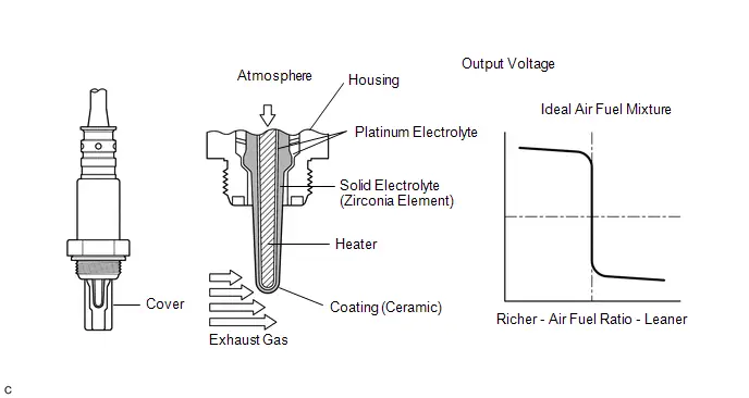
HINT:
- When any of these DTCs are stored, the ECM enters fail-safe mode. The ECM turns off the heated oxygen sensor heater in fail-safe mode. Fail-safe mode continues until the ignition switch is turned off.
-
The heated oxygen sensor heater circuit uses a relay on the B side of the circuit.
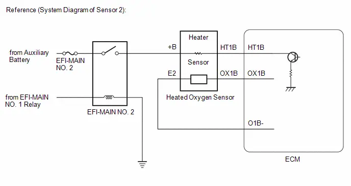
| DTC No. | Detection Item | DTC Detection Condition | Trouble Area | MIL | DTC Output from | Priority | Note |
|---|---|---|---|---|---|---|---|
| P003612 | HO2S Heater Control Circuit Bank 1 Sensor 2 Circuit Short to Battery | The heated oxygen sensor heater current is the specified value or higher while the heater is operating (1 trip detection logic). |
| Comes on | Engine | A | SAE Code: P0038 |
| P003614 | HO2S Heater Control Circuit Bank 1 Sensor 2 Circuit Short to Ground or Open | The heated oxygen sensor heater current is the specified value or less while the heater is operating (1 trip detection logic). |
| Comes on | Engine | A | SAE Code: P0037 |
| P102A9E | O2 Sensor Heater Performance Bank 1 Sensor 2 Stuck On | The heated oxygen sensor heater voltageis the specified value orless while the heater isnot operating (1 trip detection logic). |
| Comes on | Engine | A | SAE Code: P102D |
MONITOR DESCRIPTION
The sensing portion of the heated oxygen sensor has a zirconia element which is used to detect the oxygen concentration in the exhaust gas. If the zirconia element is at the appropriate temperature, and the difference between the oxygen concentrations surrounding the inside and outside surfaces of the sensor is large, the zirconia element generates voltage. In order to increase the oxygen concentration detecting capacity of the zirconia element, the ECM supplements the heat from the exhaust with heat from a heating element inside the sensor.
Heated Oxygen Sensor Heater Range Check and Heater Performance (Stuck ON):-
The ECM monitors the current applied to the heated oxygen sensor heater to check the heater for malfunctions.
If the heater current is outside the normal range, the signal transmitted by the heated oxygen sensor becomes inaccurate. When the current in the heated oxygen sensor heater is outside the normal operating range, the ECM interprets this as a malfunction of the sensor heater and stores a DTC.
MONITOR STRATEGY
| Required Sensors/Components | Heated oxygen sensor (sensor 2) heater |
| Frequency of Operation | Continuous |
TYPICAL ENABLING CONDITIONS
| Time after heater on | 5 seconds or more |
CONFIRMATION DRIVING PATTERN
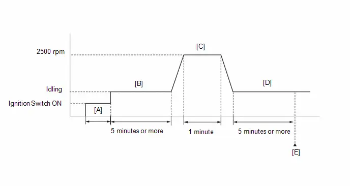
- Clear the DTCs (even if no DTCs are stored, perform the clear DTC procedure).
- Turn the ignition switch off and wait for at least 30 seconds.
- Turn the ignition switch ON [A].
-
Put the engine in Inspection Mode (Maintenance Mode).
Click here

- Start the engine and idle it for 5 minutes or more [B].
-
With the Toyota Prius vehicle stationary, depress the accelerator pedal and maintain an engine speed of 2500 rpm for 1 minute [C].
HINT:
During charge control, the engine speed is set at idle. Therefore, the engine speed will not increase when the accelerator pedal is depressed. In this case, perform steps [C] and [D] after charge control has completed.
- Idle the engine for 5 minutes or more [D].
- Enter the following menus: Powertrain / Engine / Trouble Codes [E].
-
Read the pending DTCs.
HINT:
- If a pending DTC is output, the system is malfunctioning.
- If a pending DTC is not output, perform the following procedure.
- Enter the following menus: Powertrain / Engine / Utility / All Readiness.
- Input the DTC: P003612, P003614 or P102A9E.
-
Check the DTC judgment result.
HINT:
- If the judgment result is NORMAL, the system is normal.
- If the judgment result is ABNORMAL, the system is malfunctioning.
- If the judgment result is INCOMPLETE, perform steps [B] through [E] again.
WIRING DIAGRAM
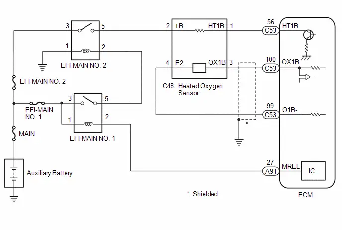
CAUTION / NOTICE / HINT
NOTICE:
- Inspect the fuses for circuits related to this system before performing the following procedure.
-
Toyota Prius Vehicle Control History may be stored in the hybrid vehicle control ECU assembly if the engine is malfunctioning. Certain vehicle condition information is recorded when Vehicle Control History is stored. Reading the vehicle conditions recorded in both the freeze frame data and Vehicle Control History can be useful for troubleshooting.
Click here

(Select Powertrain in Health Check and then check the time stamp data.)
-
If any "Engine Malfunction" Toyota Prius Vehicle Control History item has been stored in the hybrid vehicle control ECU assembly, make sure to clear it. However, as all Vehicle Control History items are cleared simultaneously, if any Vehicle Control History items other than "Engine Malfunction" are stored, make sure to perform any troubleshooting for them before clearing Toyota Prius Vehicle Control History.
Click here

HINT:
-
The operation of the heated oxygen sensor heater can be checked by referring to the Data List items "O2 Sensor Heater B1S2" and "O2 Sensor Heater Current Value B1S2".
Click here

- Sensor 1 refers to the sensor closest to the engine assembly.
- Sensor 2 refers to the sensor farthest away from the engine assembly.
- When the value of the Data List item O2 Sensor Heater Current Value B1S2 is not 0 A, the heater is on.
-
Change the fuel injection volume using the Active Test "Control the Injection Volume for A/F Sensor" and monitor the heated oxygen sensor output voltage (Click here
 ). If the heated oxygen sensor output voltage does not change (almost no reaction) while performing the Active Test, the heated oxygen sensor may be malfunctioning.
PROCEDURE
| 1. | INSPECT HEATED OXYGEN SENSOR (HEATER RESISTANCE) |
Click here

| NG |

| REPLACE HEATED OXYGEN SENSOR |
|

| 2. | CHECK TERMINAL VOLTAGE (POWER SOURCE OF HEATED OXYGEN SENSOR) |
Pre-procedure1
(a) Disconnect the heated oxygen sensor connector.
(b) Turn the ignition switch ON.
Procedure1
(c) Measure the voltage according to the value(s) in the table below.
Standard Voltage:
 Click Location & Routing(C48) Click Connector(C48)
 | Tester Connection | Condition | Specified Condition | Result |
|---|---|---|---|
| C48-2 ( B) - Body ground | Ignition switch ON | 11 to 14 V | V |
Post-procedure1
(d) None
| NG |

| GO TO STEP 6 |
|

| 3. | CHECK HARNESS AND CONNECTOR (HEATED OXYGEN SENSOR - ECM) |
Pre-procedure1
(a) Disconnect the heated oxygen sensor connector.
(b) Disconnect the ECM connector.
Procedure1
(c) Measure the resistance according to the value(s) in the table below.
Standard Resistance:
 Click Location & Routing(C48,C53) Click Connector(C48) Click Connector(C53)
 | Tester Connection | Condition | Specified Condition | Result |
|---|---|---|---|
| C48-1 (HT1B) - C53-56 (HT1B) | Always | Below 1 Ω | Ω |
| C48-1 (HT1B) or C53-56 (HT1B) - Body ground and other terminals | Always | 10 kΩ or higher | kΩ |
Post-procedure1
(d) None
| NG |

| REPAIR OR REPLACE HARNESS OR CONNECTOR |
|

| 4. | CLEAR DTC |
Pre-procedure1
(a) None
Post-procedure1
(b) Clear the DTCs.
Powertrain > Engine > Clear DTCsProcedure1
(c) Turn the ignition switch off and wait for at least 30 seconds.
|

| 5. | CHECK WHETHER DTC OUTPUT RECURS (DTC P003612, P003614 OR P102A9E) |
Pre-procedure1
(a) Drive the Toyota Prius vehicle in accordance with the driving pattern described in Confirmation Driving Pattern.
Procedure1
(b) Read the pending DTCs.
Powertrain > Engine > Trouble Codes| Result | Proceed to |
|---|---|
| DTCs are not output | A |
| P003612, P003614 or P102A9E is output | B |
Post-procedure1
(c) None
| A |

| CHECK FOR INTERMITTENT PROBLEMS |
| B |

| REPLACE ECM |
| 6. | INSPECT EFI-MAIN NO. 2 RELAY |
Click here

| NG |

| REPLACE EFI-MAIN NO. 2 RELAY |
|

| 7. | CHECK TERMINAL VOLTAGE (POWER SOURCE OF EFI-MAIN NO. 2 RELAY) |
Pre-procedure1
(a) Remove the EFI-MAIN NO. 2 relay from the No. 1 engine room relay block and No. 1 junction block assembly.
Procedure1
(b) Measure the voltage according to the value(s) in the table below.
Standard Voltage:
| Tester Connection | Condition | Specified Condition | Result |
|---|---|---|---|
| 3 (EFI-MAIN NO. 2 relay) - Body ground | Always | 11 to 14 V | V |
Post-procedure1
(c) None
| NG |

| REPAIR OR REPLACE HARNESS OR CONNECTOR (AUXILIARY BATTERY - EFI-MAIN NO. 2 RELAY) |
|

| 8. | CHECK HARNESS AND CONNECTOR (EFI-MAIN NO. 2 RELAY - BODY GROUND) |
Pre-procedure1
(a) Remove the EFI-MAIN NO. 2 relay from the No. 1 engine room relay block and No. 1 junction block assembly.
Procedure1
(b) Measure the resistance according to the value(s) in the table below.
Standard Resistance:
| Tester Connection | Condition | Specified Condition | Result |
|---|---|---|---|
| 1 (EFI-MAIN NO. 2 relay) - Body ground | Always | Below 1 Ω | Ω |
Post-procedure1
(c) None
| NG |

| REPAIR OR REPLACE HARNESS OR CONNECTOR |
|

| 9. | CHECK HARNESS AND CONNECTOR (EFI-MAIN NO. 2 RELAY - HEATED OXYGEN SENSOR) |
Pre-procedure1
(a) Remove the EFI-MAIN NO. 2 relay from the No. 1 engine room relay block and No. 1 junction block assembly.
(b) Disconnect the heated oxygen sensor connector.
Procedure1
(c) Measure the resistance according to the value(s) in the table below.
Standard Resistance:
 Click Location & Routing(C48) Click Connector(C48)
 | Tester Connection | Condition | Specified Condition | Result |
|---|---|---|---|
| 5 (EFI-MAIN NO. 2 relay) - C48-2 ( B) | Always | Below 1 Ω | Ω |
| 5 (EFI-MAIN NO. 2 relay) or C48-2 ( B) - Body ground and other terminals | Always | 10 kΩ or higher | kΩ |
Post-procedure1
(d) None
| OK |

| REPAIR OR REPLACE HARNESS OR CONNECTOR (EFI-MAIN NO. 1 RELAY - EFI-MAIN NO. 2 RELAY) |
| NG |

| REPAIR OR REPLACE HARNESS OR CONNECTOR |
Manifold Absolute Pressure - Barometric Pressure Correlation (P006900)
DESCRIPTION
The manifold absolute pressure sensor installed to the intake manifold detects the intake manifold pressure using a built-in sensor.
An atmospheric pressure sensor is built in the ECM. When the engine is stopped, the value of the manifold absolute pressure sensor and atmospheric pressure sensor will be approximately the same as the atmospheric pressure.
| DTC No. | Detection Item | DTC Detection Condition | Trouble Area | MIL | DTC Output from | Priority | Note |
|---|---|---|---|---|---|---|---|
| P006900 | Manifold Absolute Pressure - Barometric Pressure Correlation | Difference between atmospheric pressure value of the absolute pressure sensor and atmospheric pressure sensor is higher than threshold value (2 trip detection logic). |
| Comes on | Engine | B | SAE Code: P0069 |
MONITOR DESCRIPTION
Approximately 50 minutes after the ignition switch is turned off, the soak timer is activated and the values of the manifold absolute pressure sensor and atmospheric pressure sensor are compared. If the difference between the values of the manifold absolute pressure sensor and atmospheric pressure sensor is higher than a threshold value in consecutive driving cycles, the ECM will store this DTC.
MONITOR STRATEGY
| Required Sensors/Components (Main) | Manifold absolute pressure sensor ECM |
| Required Sensors/Components (Related) | Mass air flow meter sub-assembly Engine coolant temperature sensor |
| Frequency of Operation | Once per driving cycle |
CONFIRMATION DRIVING PATTERN
- Clear the DTCs (even if no DTCs are stored, perform the clear DTC procedure).
- Turn the ignition switch off and wait for at least 55 minutes.
- Turn the ignition switch ON.
- Enter the following menus: Powertrain / Engine / Trouble Codes.
-
Read the pending DTCs.
HINT:
- If a pending DTC is output, the system is malfunctioning.
- If a pending DTC is not output, perform the following procedure.
- Enter the following menus: Powertrain / Engine / Utility / All Readiness.
- Input the DTC: P006900.
-
Check the DTC judgment result.
HINT:
- If the judgment result is NORMAL, the system is normal.
- If the judgment result is ABNORMAL, the system is malfunctioning.
CAUTION / NOTICE / HINT
NOTICE:
-
Toyota Prius Vehicle Control History may be stored in the hybrid vehicle control ECU assembly if the engine is malfunctioning. Certain vehicle condition information is recorded when Vehicle Control History is stored. Reading the vehicle conditions recorded in both the freeze frame data and Vehicle Control History can be useful for troubleshooting.
Click here

(Select Powertrain in Health Check and then check the time stamp data.)
-
If any "Engine Malfunction" Toyota Prius Vehicle Control History item has been stored in the hybrid vehicle control ECU assembly, make sure to clear it. However, as all Vehicle Control History items are cleared simultaneously, if any Vehicle Control History items other than "Engine Malfunction" are stored, make sure to perform any troubleshooting for them before clearing Toyota Prius Vehicle Control History.
Click here

PROCEDURE
| 1. | CHECK ANY OTHER DTCS OUTPUT (IN ADDITION TO DTC P006900) |
(a) Read the DTCs.
Powertrain > Engine > Trouble Codes| Result | Proceed to |
|---|---|
| P006900 and other DTCs are output | A |
| P006900 is output | B |
HINT:
If any DTCs other than P006900 are output, troubleshoot those DTCs first.
| A |

| GO TO DTC CHART |
|

| 2. | READ VALUE USING GTS (INTAKE MANIFOLD ABSOLUTE PRESSURE) |
Pre-procedure1
(a) Turn the ignition switch off and wait for at least 50 minutes.
(b) Turn the ignition switch ON.
(c) Using the following table, determine the normal atmospheric pressure for the current altitude and temperature.
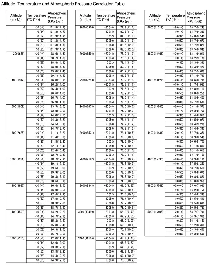
HINT:
- Standard atmospheric pressure is approximately 101 kPa(abs) [15 psi(abs)].
- For every 100 m (328 ft.) increase in altitude, atmospheric pressure drops by approximately 1 kPa (0.1 psi). This varies depending on the weather.
Procedure1
(d) Compare the value of the Data List item Intake Manifold Absolute Pressure with the actual atmospheric pressure.
Powertrain > Engine > Data List| Tester Display |
|---|
| Intake Manifold Absolute Pressure |
| Result | Proceed to |
|---|---|
| Approximately the same as the actual atmospheric pressure | A |
| Not approximately the same as the actual atmospheric pressure | B |
Post-procedure1
(e) None
| B |

| REPLACE MANIFOLD ABSOLUTE PRESSURE SENSOR |
|

| 3. | READ VALUE USING GTS (ATMOSPHERIC PRESSURE) |
Pre-procedure1
(a) Using the following table, determine the normal atmospheric pressure for the current altitude and temperature.

HINT:
- Standard atmospheric pressure is approximately 101 kPa(abs) [15 psi(abs)].
- For every 100 m (328 ft.) increase in altitude, atmospheric pressure drops by approximately 1 kPa (0.1 psi). This varies depending on the weather.
Procedure1
(b) Compare the value of the Data List item Atmospheric Pressure with the actual atmospheric pressure.
Powertrain > Engine > Data List| Tester Display |
|---|
| Atmospheric Pressure |
| Result | Proceed to |
|---|---|
| Approximately the same as the actual atmospheric pressure | A |
| Not approximately the same as the actual atmospheric pressure | B |
Post-procedure1
(c) None
| A |

| CHECK FOR INTERMITTENT PROBLEMS |
| B |

| REPLACE ECM |
Mass or Volume Air Flow Sensor "A" Circuit Short to Battery (P010012,P010014)
DESCRIPTION
The mass air flow meter sub-assembly is a sensor that measures the intake air volume using the following built-in components:
- By-pass passage (allows some of the intake air to flow past a silicon chip sensor)
- Silicon chip sensor (uses a heater control bridge circuit and temperature sensor bridge circuit to detect the difference in the temperature of the intake air that passes the sensors positioned before and after the heater).
- Control circuit (converts the difference in temperature into a pulse signal and performs correction)
Intake air flows over the temperature sensor (before heater), the heater, and then the temperature sensor (after heater) on the silicon chip sensor in the by-pass passage. As the intake air is warmed up when it is exposed to the heater, the temperature of the intake air flowing over the temperature sensor (after heater) is higher than that over the temperature sensor (before heater). The difference in temperature of the intake air at each temperature sensor varies depending on the velocity of the intake air that flows over the silicon chip sensor. The temperature sensor bridge circuit detects the difference in temperature and the control circuit converts it into a pulse signal and outputs it to the ECM. When the temperature detected by the temperature sensor (before heater) is higher than that detected by the temperature sensor (after heater), backflow of the intake air is detected.
The ECM calculates the intake air amount based on the pulse signal received from the mass air flow meter sub-assembly, and uses it to determine the fuel injection duration necessary for an optimal air-fuel ratio.
The heater control bridge circuit includes temperature sensors and power transistor, and maintains the heater temperature at a specific temperature.
HINT:
When DTCs are stored, the ECM enters fail-safe mode. During fail-safe mode, the ECM calculates the fuel injection duration based on the engine speed and throttle valve angle. Fail-safe mode continues until a pass condition is detected.
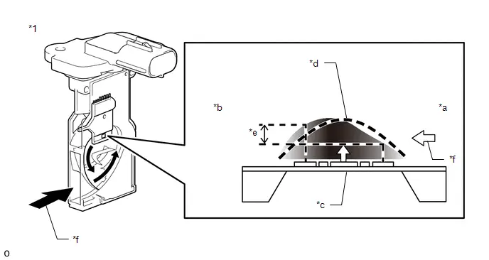
| *1 | Mass Air Flow Meter Sub-assembly | - | - |
| *a | Upstream Side | *b | Downstream Side |
| *c | Heater | *d | Temperature Distribution WithoutAirflow |
| *e | Flow Rate Detection by TemperatureDifferential | *f | Intake Air |
| DTC No. | Detection Item | DTC Detection Condition | Trouble Area | MIL | DTC Output from | Priority | Note |
|---|---|---|---|---|---|---|---|
| P010012 | Mass or Volume Air Flow Sensor "A" Circuit Short to Battery | The mass air flow meter sub-assembly output frequency is higher than 9.8 kHz for 3 seconds or more (1 trip detection logic). |
| Comes on | Engine | A | SAE Code: P0103 |
| P010014 | Mass or Volume Air Flow Sensor "A" Circuit Short to Ground or Open | The mass air flow meter sub-assembly output frequency is less than 0.1 kHz for 3 seconds or more (1 trip detection logic). |
| Comes on | Engine | A | SAE Code: P0102 |
MONITOR DESCRIPTION
If there is a defect or an open or short circuit in the mass air flow meter sub-assembly, the frequency level deviates from the normal operating range. The ECM interprets this deviation as a malfunction in the mass air flow meter sub-assembly circuit and stores a DTC.
Example:
When the sensor output frequency remains less than 0.1 kHz, or higher than 9.8 kHz for 3 seconds, the ECM stores a DTC.
MONITOR STRATEGY
| Frequency of Operation | Continuous |
CONFIRMATION DRIVING PATTERN
- Clear the DTCs (even if no DTCs are stored, perform the clear DTC procedure).
- Turn the ignition switch off and wait for at least 30 seconds.
- Turn the ignition switch ON.
- Wait 5 seconds or more [A].
- Enter the following menus: Powertrain / Engine / Trouble Codes [B].
-
Read the pending DTCs.
HINT:
- If a pending DTC is output, the system is malfunctioning.
- If a pending DTC is not output, perform the following procedure.
- Enter the following menus: Powertrain / Engine / Utility / All Readiness.
- Input the DTC: P010012 or P010014.
-
Check the DTC judgment result.
HINT:
- If the judgment result is NORMAL, the system is normal.
- If the judgment result is ABNORMAL, the system has a malfunction.
- If the judgment result is INCOMPLETE, perform steps [A] through [B] again.
-
[A] to [B]: Normal judgment procedure.
The normal judgment procedure is used to complete DTC judgment and also used when clearing permanent DTCs.
- When clearing the permanent DTCs, do not disconnect the cable from the auxiliary battery terminal or attempt to clear the DTCs during this procedure, as doing so will clear the universal trip and normal judgment histories.
WIRING DIAGRAM
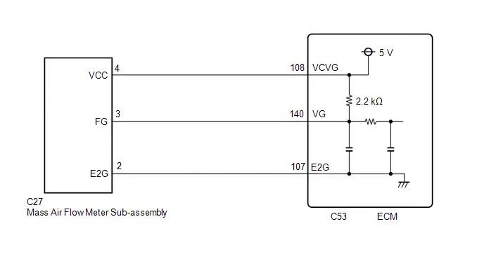
CAUTION / NOTICE / HINT
NOTICE:
-
Toyota Prius Vehicle Control History may be stored in the hybrid vehicle control ECU if the engine is malfunctioning. Certain vehicle condition information is recorded when Vehicle Control History is stored. Reading the vehicle conditions recorded in both the freeze frame data and Vehicle Control History can be useful for troubleshooting.
Click here

(Select Powertrain in Health Check and then check the time stamp data.)
-
If any "Engine Malfunction" Toyota Prius Vehicle Control History item has been stored in the hybrid vehicle control ECU, make sure to clear it. However, as all Vehicle Control History items are cleared simultaneously, if any Vehicle Control History items other than "Engine Malfunction" are stored, make sure to perform any troubleshooting for them before clearing Toyota Prius Vehicle Control History.
Click here

PROCEDURE
| 1. | CHECK HARNESS AND CONNECTOR |
Pre-procedure1
(a) Disconnect the mass air flow meter sub-assembly connector.
(b) Turn the ignition switch ON.
Procedure1
(c) Measure the voltage according to the value(s) in the table below.
Standard Voltage:
 Click Location & Routing(C27) Click Connector(C27)
 | Tester Connection | Condition | Specified Condition | Result |
|---|---|---|---|
| C27-4 (VCC) - C27-2 (E2G) | Ignition switch ON | 4.8 to 5.2 V | V |
| C27-3 (FG) - C27-2 (E2G) | Ignition switch ON | 4.8 to 5.2 V | V |
Post-procedure1
(d) Turn the ignition switch off and wait for at least 30 seconds.
Pre-procedure2
(e) None
Procedure2
(f) Measure the resistance according to the value(s) in the table below.
Standard Resistance:
 Click Location & Routing(C27) Click Connector(C27)
 | Tester Connection | Condition | Specified Condition | Result |
|---|---|---|---|
| C27-4 (VCC) - C27-3 (FG) | Ignition switch off | 2.09 to 2.31 kΩ | kΩ |
Post-procedure2
(g) None
| NG |

| GO TO STEP 5 |
|

| 2. | INSPECT MASS AIR FLOW METER SUB-ASSEMBLY |
Click here

|

| 3. | CLEAR DTC |
Pre-procedure1
(a) None
Procedure1
(b) Clear the DTCs.
Powertrain > Engine > Clear DTCsPost-procedure1
(c) Turn the ignition switch off and wait for at least 30 seconds.
|

| 4. | CHECK WHETHER DTC OUTPUT RECURS (DTC P010012 OR P010014) |
Pre-procedure1
(a) Drive the Toyota Prius vehicle in accordance with the driving pattern described in Confirmation Driving Pattern.
Procedure1
(b) Read the DTCs.
Powertrain > Engine > Trouble Codes| Result | Proceed to |
|---|---|
| DTCs are not output | A |
| P010012 or P010014 is output | B |
Post-procedure1
(c) None
| A |

| END |
| B |

| REPLACE ECM |
| 5. | CHECK HARNESS AND CONNECTOR (MASS AIR FLOW METER SUB-ASSEMBLY - ECM) |
Pre-procedure1
(a) Disconnect the mass air flow meter sub-assembly connector.
(b) Disconnect the ECM connector.
Procedure1
(c) Measure the resistance according to the value(s) in the table below.
Standard Resistance:
 Click Location & Routing(C27,C53) Click Connector(C27) Click Connector(C53)
 | Tester Connection | Condition | Specified Condition | Result |
|---|---|---|---|
| C27-4 (VCC) - C53-108 (VCVG) | Always | Below 1 Ω | Ω |
| C27-3 (FG) - C53-140 (VG) | Always | Below 1 Ω | Ω |
| C27-2 (E2G) - C53-107 (E2G) | Always | Below 1 Ω | Ω |
| C27-4 (VCC) or C53-108 (VCVG) - Body ground and other terminals | Always | 10 kΩ or higher | kΩ |
| C27-3 (FG) or C53-140 (VG) - Body ground and other terminals | Always | 10 kΩ or higher | kΩ |
| C27-2 (E2G) or C53-107 (E2G) - Body ground and other terminals | Always | 10 kΩ or higher | kΩ |
Post-procedure1
(d) None
| OK |

| REPLACE ECM |
| NG |

| REPAIR OR REPLACE HARNESS OR CONNECTOR |
Manifold Absolute Pressure / Barometric Pressure Sensor Circuit Short to Ground (P010511)
DESCRIPTION
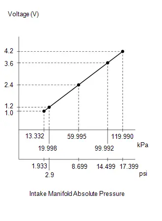
The manifold absolute pressure sensor detects the intake manifold pressure as a change in voltage. The ECM calculates the intake manifold pressure based on this voltage. The ECM calculates the EGR valve assembly and purge VSV opening amount according to changes in the intake manifold pressure and also detects malfunctions of the manifold absolute pressure sensor using these changes in pressure.
| DTC No. | Detection Item | DTC Detection Condition | Trouble Area | MIL | DTC Output from | Priority | Note |
|---|---|---|---|---|---|---|---|
| P010511 | Manifold Absolute Pressure / Barometric Pressure Sensor Circuit Short to Ground | The manifold absolute pressure sensor output voltage is less than 0.5 V for 0.5 seconds or more (1 trip detection logic). |
| Comes on | Engine | A | SAE Code: P0107 |
HINT:
When this DTC is output, check the intake manifold absolute pressure in the Data List. Enter the following menus: Powertrain / Engine / Data List / Intake Manifold Absolute Pressure.
| DTC No. | Intake Manifold Absolute Pressure | Malfunction |
|---|---|---|
| P010511 | Approximately 0 kPa (0 psi) |
|
If the Data List value is normal it may be due to a temporary recovery from the malfunction condition. Check for intermittent problems.
MONITOR DESCRIPTION
The ECM monitors the manifold absolute pressure sensor voltage and uses this value to calculate the intake manifold pressure. When the manifold absolute pressure sensor output voltage deviates from the normal operating range, the ECM interprets this as a malfunction in the manifold absolute pressure circuit, illuminates the MIL and stores a DTC.
Example:
If the manifold absolute pressure sensor output voltage is less than 0.5 V for 0.5 seconds or more, the ECM stores this DTC.
MONITOR STRATEGY
| Frequency of Operation | Continuous |
CONFIRMATION DRIVING PATTERN
- Clear the DTCs (even if no DTCs are stored, perform the clear DTC procedure).
- Turn the ignition switch off and wait for at least 30 seconds.
- Turn the ignition switch ON.
-
Put the engine in Inspection Mode (Maintenance Mode).
Click here

- Start the engine and wait 5 seconds or more.
- Enter the following menus: Powertrain / Engine / Trouble Codes.
-
Read the pending DTCs.
HINT:
- If a pending DTC is output, the system is malfunctioning.
- If a pending DTC is not output, perform the following procedure.
- Enter the following menus: Powertrain / Engine / Utility / All Readiness.
- Input the DTC: P010511.
-
Check the DTC judgment result.
HINT:
- If the judgment result is NORMAL, the system is normal.
- If the judgment result is ABNORMAL, the system is malfunctioning.
- If the judgment result is INCOMPLETE, perform the Confirmation Driving Pattern and check the DTC judgment result again.
WIRING DIAGRAM
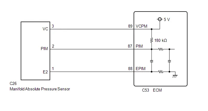
CAUTION / NOTICE / HINT
NOTICE:
-
Toyota Prius Vehicle Control History may be stored in the hybrid vehicle control ECU assembly if the engine is malfunctioning. Certain vehicle condition information is recorded when Vehicle Control History is stored. Reading the vehicle conditions recorded in both the freeze frame data and Vehicle Control History can be useful for troubleshooting.
Click here

(Select Powertrain in Health Check and then check the time stamp data.)
-
If any "Engine Malfunction" Toyota Prius Vehicle Control History item has been stored in the hybrid vehicle control ECU assembly, make sure to clear it. However, as all Vehicle Control History items are cleared simultaneously, if any Vehicle Control History items other than "Engine Malfunction" are stored, make sure to perform any troubleshooting for them before clearing Toyota Prius Vehicle Control History.
Click here

PROCEDURE
| 1. | CHECK HARNESS AND CONNECTOR |
HINT:
Make sure that the connector is properly connected. If it is not, securely connect it and check for DTCs again.
Pre-procedure1
(a) Disconnect the manifold absolute pressure sensor connector.
(b) Turn the ignition switch ON.
Procedure1
(c) Measure the voltage according to the value(s) in the table below.
Standard Voltage:
 Click Location & Routing(C26) Click Connector(C26)
 | Tester Connection | Condition | Specified Condition | Result |
|---|---|---|---|
| C26-3 (VC) - C26-1 (E2) | Ignition switch ON | 4.75 to 5.25 V | V |
| C26-2 (PIM) - C26-1 (E2) | Ignition switch ON | 3.0 to 5.25 V | V |
Post-procedure1
(d) Turn the ignition switch off and wait for at least 30 seconds.
Pre-procedure2
(e) None
Procedure2
(f) Measure the resistance according to the value(s) in the table below.
Standard Resistance:
 Click Location & Routing(C26) Click Connector(C26)
 | Tester Connection | Condition | Specified Condition | Result |
|---|---|---|---|
| C26-3 (VC) - C26-2 (PIM) | Ignition switch off | 171 to 189 kΩ | kΩ |
Post-procedure2
(g) None
| OK |

| REPLACE MANIFOLD ABSOLUTE PRESSURE SENSOR |
|

| 2. | CHECK HARNESS AND CONNECTOR (MANIFOLD ABSOLUTE PRESSURE SENSOR - ECM) |
Pre-procedure1
(a) Disconnect the manifold absolute pressure sensor connector.
(b) Disconnect the ECM connector.
Procedure1
(c) Measure the resistance according to the value(s) in the table below.
Standard Resistance:
 Click Location & Routing(C26,C53) Click Connector(C26) Click Connector(C53)
 | Tester Connection | Condition | Specified Condition | Result |
|---|---|---|---|
| C26-3 (VC) - C53-89 (VCPM) | Always | Below 1 Ω | Ω |
| C26-2 (PIM) or C53-87 (PIM) - Body ground and other terminals | Always | 10 kΩ or higher | kΩ |
Post-procedure1
(d) None
| OK |

| REPLACE ECM |
| NG |

| REPAIR OR REPLACE HARNESS OR CONNECTOR |
Manifold Absolute Pressure / Barometric Pressure Sensor Circuit Short to Battery or Open (P010515)
DESCRIPTION
Refer to DTC P010511.
Click here

| DTC No. | Detection Item | DTC Detection Condition | Trouble Area | MIL | DTC Output from | Priority | Note |
|---|---|---|---|---|---|---|---|
| P010515 | Manifold Absolute Pressure / Barometric Pressure Sensor Circuit Short to Battery or Open | The manifold absolute pressure sensor output voltage is higher than 4.5 V for 0.5 seconds or more (1 trip detection logic). |
| Comes on | Engine | A | SAE Code: P0108 |
HINT:
When this DTC is output, check the intake manifold absolute pressure in the Data List. Enter the following menus: Powertrain / Engine / Data List / Intake Manifold Absolute Pressure.
| DTC No. | Intake Manifold Absolute Pressure | Malfunction |
|---|---|---|
| P010515 | Higher than 130 kPa (18.85 psi) |
|
If the Data List value is normal it may be due to a temporary recovery from the malfunction condition. Check for intermittent problems.
MONITOR DESCRIPTION
The ECM monitors the manifold absolute pressure sensor voltage and uses this value to calculate the intake manifold pressure. When the manifold absolute pressure sensor output voltage deviates from the normal operating range, the ECM interprets this as a malfunction in the manifold absolute pressure sensor circuit, illuminates the MIL and stores a DTC.
Example:
If the manifold absolute pressure sensor output voltage is higher than 4.5 V for 0.5 seconds or more, the ECM stores this DTC
MONITOR STRATEGY
| Frequency of Operation | Continuous |
CONFIRMATION DRIVING PATTERN
- Clear the DTCs (even if no DTCs are stored, perform the clear DTC procedure).
- Turn the ignition switch off and wait for at least 30 seconds.
- Turn the ignition switch ON.
-
Put the engine in Inspection Mode (Maintenance Mode).
Click here

- Start the engine and wait 5 seconds or more.
- Enter the following menus: Powertrain / Engine / Trouble Codes.
-
Read the pending DTCs.
HINT:
- If a pending DTC is output, the system is malfunctioning.
- If a pending DTC is not output, perform the following procedure.
- Enter the following menus: Powertrain / Engine / Utility / All Readiness.
- Input the DTC: P010515.
-
Check the DTC judgment result.
HINT:
- If the judgment result is NORMAL, the system is normal.
- If the judgment result is ABNORMAL, the system is malfunctioning.
- If the judgment result is INCOMPLETE, perform the Confirmation Driving Pattern and check the DTC judgment result again.
WIRING DIAGRAM
Refer to DTC P010511.
Click here

CAUTION / NOTICE / HINT
NOTICE:
-
Toyota Prius Vehicle Control History may be stored in the hybrid vehicle control ECU assembly if the engine is malfunctioning. Certain vehicle condition information is recorded when Vehicle Control History is stored. Reading the vehicle conditions recorded in both the freeze frame data and Vehicle Control History can be useful for troubleshooting.
Click here

(Select Powertrain in Health Check and then check the time stamp data.)
-
If any "Engine Malfunction" Toyota Prius Vehicle Control History item has been stored in the hybrid vehicle control ECU assembly, make sure to clear it. However, as all Vehicle Control History items are cleared simultaneously, if any Vehicle Control History items other than "Engine Malfunction" are stored, make sure to perform any troubleshooting for them before clearing Toyota Prius Vehicle Control History.
Click here

PROCEDURE
| 1. | CHECK HARNESS AND CONNECTOR |
HINT:
Make sure that the connector is properly connected. If it is not, securely connect it and check for DTCs again.
Pre-procedure1
(a) Disconnect the manifold absolute pressure sensor connector.
(b) Turn the ignition switch ON.
Procedure1
(c) Measure the voltage according to the value(s) in the table below.
Standard Voltage:
 Click Location & Routing(C26) Click Connector(C26)
 | Tester Connection | Condition | Specified Condition | Result |
|---|---|---|---|
| C26-3 (VC) - C26-1 (E2) | Ignition switch ON | 4.75 to 5.25 V | V |
| C26-2 (PIM) - C26-1 (E2) | Ignition switch ON | 3.0 to 5.25 V | V |
Post-procedure1
(d) Turn the ignition switch off and wait for at least 30 seconds.
Pre-procedure2
(e) None
Procedure2
(f) Measure the resistance according to the value(s) in the table below.
Standard Resistance:
 Click Location & Routing(C26) Click Connector(C26)
 | Tester Connection | Condition | Specified Condition | Result |
|---|---|---|---|
| C26-1 (E2) - Body ground | Ignition switch off | Below 1 Ω | Ω |
| C26-3 (VC) - C26-2 (PIM) | Ignition switch off | 171 to 189 kΩ | kΩ |
Post-procedure2
(g) None
| OK |

| REPLACE MANIFOLD ABSOLUTE PRESSURE SENSOR |
|

| 2. | CHECK HARNESS AND CONNECTOR (MANIFOLD ABSOLUTE PRESSURE SENSOR - ECM) |
Pre-procedure1
(a) Disconnect the manifold absolute pressure sensor connector.
(b) Disconnect the ECM connector.
Procedure1
(c) Measure the resistance according to the value(s) in the table below.
Standard Resistance:
 Click Location & Routing(C26,C53) Click Connector(C26) Click Connector(C53)
 | Tester Connection | Condition | Specified Condition | Result |
|---|---|---|---|
| C26-1 (E2) - C53-88 (EPIM) | Always | Below 1 Ω | Ω |
| C26-2 (PIM) - C53-87 (PIM) | Always | Below 1 Ω | Ω |
| C26-2 (PIM) or C53-87 (PIM) - Other terminals | Always | 10 kΩ or higher | kΩ |
Post-procedure1
(d) None
| OK |

| REPLACE ECM |
| NG |

| REPAIR OR REPLACE HARNESS OR CONNECTOR |
Intake Air Temperature Sensor 1 Bank 1 Circuit Short to Ground (P011011)
DESCRIPTION
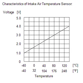
The intake air temperature sensor, mounted on the mass air flow meter sub-assembly, monitors the intake air temperature. The intake air temperature sensor has a built-in thermistor with a resistance that varies according to the temperature of the intake air. When the intake air temperature is low, the resistance of the thermistor increases. When the temperature is high, the resistance drops. These variations in resistance are transmitted to the ECM as voltage changes.
The intake air temperature detected by the inlet air temperature sensor is converted to a voltage value inside the intake airflow meter assembly, and the voltage value is then output to the ECM. Based on this signal, the ECM increases the fuel injection volume when the engine is cold to improve driveability.
HINT:
When DTC P011011 is stored, the ECM enters fail-safe mode. During fail-safe mode, the intake air temperature is estimated to be 20°C (68°F) by the ECM. Fail-safe mode continues until a pass condition is detected.
| DTC No. | Detection Item | DTC Detection Condition | Trouble Area | MIL | DTC Output from | Priority | Note |
|---|---|---|---|---|---|---|---|
| P011011 | Intake Air Temperature Sensor 1 Bank 1 Circuit Short to Ground | The intake air temperature sensor output voltage is below 0.663 V for 0.5 seconds or more (1 trip detection logic). |
| Comes on | Engine | A | SAE Code: P0112 |
HINT:
When this DTC is output, check the intake air temperature in the Data List. Enter the following menus: Powertrain / Engine / Data List / Intake Air Temperature.
| DTC No. | Intake Air Temperature | Malfunction |
|---|---|---|
| P011011 | -40°C (-40°F) or less |
|
If the Data List value is normal it may be due to a temporary recovery from the malfunction condition. Check for intermittent problems.
Click here

MONITOR DESCRIPTION
When the ignition switch is turned ON and the output voltage of the intake air temperature sensor is less than 0.142 V for 0.5 seconds or more, the ECM determines that the intake air temperature sensor circuit is malfunctioning and illuminates the MIL and stores a DTC.
MONITOR STRATEGY
| Frequency of Operation | Continuous |
CONFIRMATION DRIVING PATTERN
- Clear the DTCs (even if no DTCs are stored, perform the clear DTC procedure).
- Turn the ignition switch off and wait for at least 30 seconds.
- Turn the ignition switch ON.
- Wait 0.5 seconds or more.
- Enter the following menus: Powertrain / Engine / Trouble Codes.
-
Read the pending DTCs.
HINT:
- If a pending DTC is output, the system is malfunctioning.
- If a pending DTC is not output, perform the following procedure.
- Enter the following menus: Powertrain / Engine / Utility / All Readiness.
- Proceed to the next screen and enter the DTC to be checked.
-
Check the DTC judgment result.
HINT:
- If the judgment result is NORMAL, the system is normal.
- If the judgment result is ABNORMAL, the system is malfunctioning.
WIRING DIAGRAM
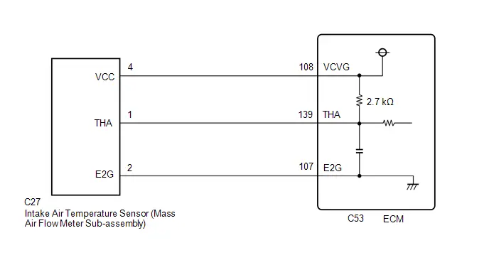
CAUTION / NOTICE / HINT
NOTICE:
-
Toyota Prius Vehicle Control History may be stored in the hybrid vehicle control ECU assembly if the engine is malfunctioning. Certain vehicle condition information is recorded when Vehicle Control History is stored. Reading the vehicle conditions recorded in both the freeze frame data and Vehicle Control History can be useful for troubleshooting.
Click here

(Select Powertrain in Health Check and then check the time stamp data.)
-
If any "Engine Malfunction" Toyota Prius Vehicle Control History item has been stored in the hybrid vehicle control ECU assembly, make sure to clear it. However, as all Vehicle Control History items are cleared simultaneously, if any Vehicle Control History items other than "Engine Malfunction" are stored, make sure to perform any troubleshooting for them before clearing Toyota Prius Vehicle Control History.
Click here

PROCEDURE
| 1. | CHECK HARNESS AND CONNECTOR |
HINT:
Make sure that the connector is properly connected. If it is not, securely connect it and check for DTCs again.
Pre-procedure1
(a) Disconnect the mass air flow meter sub-assembly connector.
(b) Turn the ignition switch ON.
Procedure1
(c) Measure the voltage according to the value(s) in the table below.
Standard Voltage:
 Click Location & Routing(C27) Click Connector(C27)
 | Tester Connection | Condition | Specified Condition | Result |
|---|---|---|---|
| C27-4 (VCC) - C27-2 (E2G) | Ignition switch ON | 4.8 to 5.2 V | V |
| C27-1 (THA) - C27-2 (E2G) | Ignition switch ON | 4.8 to 5.2 V | V |
Post-procedure1
(d) Turn the ignition switch off and wait for at least 30 seconds.
Pre-procedure2
(e) None
Procedure2
(f) Measure the resistance according to the value(s) in the table below.
Standard Resistance:
 Click Location & Routing(C27) Click Connector(C27)
 | Tester Connection | Condition | Specified Condition | Result |
|---|---|---|---|
| C27-4 (VCC) - C27-1 (THA) | Ignition switch ON | 2.565 to 2.835 kΩ | kΩ |
Post-procedure2
(g) None
| OK |

| REPLACE MASS AIR FLOW METER SUB-ASSEMBLY |
|

| 2. | CHECK HARNESS AND CONNECTOR (INTAKE AIR TEMPERATURE SENSOR - ECM) |
Pre-procedure1
(a) Disconnect the mass air flow meter sub-assembly connector.
(b) Disconnect the ECM connector.
Procedure1
(c) Measure the resistance according to the value(s) in the table below.
Standard Resistance:
 Click Location & Routing(C27,C53) Click Connector(C27) Click Connector(C53)
 | Tester Connection | Condition | Specified Condition | Result |
|---|---|---|---|
| C27-4 (VCC) - C53-108 (VCVG) | Always | Below 1 Ω | Ω |
| C27-1 (THA) or C53-139 (THA) - Body ground and other terminals | Always | 10 kΩ or higher | kΩ |
Post-procedure1
(d) None
| OK |

| REPLACE ECM |
| NG |

| REPAIR OR REPLACE HARNESS OR CONNECTOR |
Intake Air Temperature Sensor 1 Bank 1 Circuit Short to Battery or Open (P011015)
DESCRIPTION
Refer to DTC P011011.
Click here

HINT:
When DTC P011015 is stored, the ECM enters fail-safe mode. During fail-safe mode, the intake air temperature is estimated to be 20°C (68°F) by the ECM. Fail-safe mode continues until a pass condition is detected.
| DTC No. | Detection Item | DTC Detection Condition | Trouble Area | MIL | DTC Output from | Priority | Note |
|---|---|---|---|---|---|---|---|
| P011015 | Intake Air Temperature Sensor 1 Bank 1 Circuit Short to Battery or Open | The intake air temperature sensor output voltage is higher than 3.76 V for 0.5 seconds or more (1 trip detection logic). |
| Comes on | Engine | A | SAE Code: P0113 |
HINT:
When this DTC is output, check the intake air temperature in the Data List. Enter the following menus: Powertrain / Engine / Data List / Intake Air Temperature.
| DTC No. | Intake Air Temperature | Malfunction |
|---|---|---|
| P011015 | Higher than 123°C (253°F) |
|
If the Data List value is normal it may be due to a temporary recovery from the malfunction condition. Check for intermittent problems.
Click here

MONITOR DESCRIPTION
When the ignition switch is turned ON and the output voltage of the intake air temperature sensor is higher than 3.76 V for 0.5 seconds or more, the ECM determines that the intake air temperature sensor circuit is malfunctioning and illuminates the MIL and stores a DTC.
MONITOR STRATEGY
| Frequency of Operation | Continuous |
CONFIRMATION DRIVING PATTERN
Refer to DTC P011011.
Click here

WIRING DIAGRAM
Refer to DTC P011011.
Click here

CAUTION / NOTICE / HINT
NOTICE:
-
Toyota Prius Vehicle Control History may be stored in the hybrid vehicle control ECU assembly if the engine is malfunctioning. Certain vehicle condition information is recorded when Vehicle Control History is stored. Reading the vehicle conditions recorded in both the freeze frame data and Vehicle Control History can be useful for troubleshooting.
Click here

(Select Powertrain in Health Check and then check the time stamp data.)
-
If any "Engine Malfunction" Toyota Prius Vehicle Control History item has been stored in the hybrid vehicle control ECU assembly, make sure to clear it. However, as all Vehicle Control History items are cleared simultaneously, if any Vehicle Control History items other than "Engine Malfunction" are stored, make sure to perform any troubleshooting for them before clearing Toyota Prius Vehicle Control History.
Click here

PROCEDURE
| 1. | CHECK HARNESS AND CONNECTOR |
HINT:
Make sure that the connector is properly connected. If it is not, securely connect it and check for DTCs again.
Pre-procedure1
(a) Disconnect the mass air flow meter sub-assembly connector.
(b) Turn the ignition switch ON.
Procedure1
(c) Measure the voltage according to the value(s) in the table below.
Standard Voltage:
 Click Location & Routing(C27) Click Connector(C27)
 | Tester Connection | Condition | Specified Condition | Result |
|---|---|---|---|
| C27-4 (VCC) - C27-2 (E2G) | Ignition switch ON | 4.8 to 5.2 V | V |
| C27-1 (THA) - C27-2 (E2G) | Ignition switch ON | 4.8 to 5.2 V | V |
Post-procedure1
(d) Turn the ignition switch off and wait for at least 30 seconds.
Pre-procedure2
(e) None
Procedure2
(f) Measure the resistance according to the value(s) in the table below.
Standard Resistance:
 Click Location & Routing(C27) Click Connector(C27)
 | Tester Connection | Condition | Specified Condition | Result |
|---|---|---|---|
| C27-2 (E2G) - Body ground | Ignition switch off | Below 1 Ω | Ω |
| C27-4 (VCC) - C27-1 (THA) | Always | 2.565 to 2.835 kΩ | kΩ |
Post-procedure2
(g) None
| OK |

| REPLACE MASS AIR FLOW METER SUB-ASSEMBLY |
|

| 2. | CHECK HARNESS AND CONNECTOR (INTAKE AIR TEMPERATURE SENSOR - ECM) |
Pre-procedure1
(a) Disconnect the mass air flow meter sub-assembly connector.
(b) Disconnect the ECM connector.
Procedure1
(c) Measure the resistance according to the value(s) in the table below.
Standard Resistance:
 Click Location & Routing(C27,C53) Click Connector(C27) Click Connector(C53)
 | Tester Connection | Condition | Specified Condition | Result |
|---|---|---|---|
| C27-1 (THA) - C53-139 (THA) | Always | Below 1 Ω | Ω |
| C27-2 (E2G) - C53-107 (E2G) | Always | Below 1 Ω | Ω |
| C27-1 (THA) or C53-139 (THA) - Other terminals | Always | 10 kΩ or higher | kΩ |
Post-procedure1
(d) None
| OK |

| REPLACE ECM |
| NG |

| REPAIR OR REPLACE HARNESS OR CONNECTOR |
Engine Coolant Temperature Sensor 1 Circuit Short to Ground (P011511)
DESCRIPTION
A thermistor, whose resistance value varies according to the engine coolant temperature, is built into the engine coolant temperature sensor. The structure of the thermistor in the engine coolant temperature sensor and its connection to the ECM are the same as those of the intake air temperature sensor.
Refer to DTC P011011.
Click here

HINT:
When DTC P011511 is stored, the ECM enters fail-safe mode. During fail-safe mode, the engine coolant temperature is estimated to be 80°C (176°F) by the ECM. Fail-safe mode continues until a pass condition is detected.
| DTC No. | Detection Item | DTC Detection Condition | Trouble Area | MIL | DTC Output from | Priority | Note |
|---|---|---|---|---|---|---|---|
| P011511 | Engine Coolant Temperature Sensor 1 Circuit Short to Ground | Diagnosis condition:
Abnormal condition:
Malfunction time:
Trip logic:
Detection conditions:
Sensors/components used for detection:
|
| Comes on | Engine | A | SAE Code: P0117 |
HINT:
When this DTC is output, check the engine coolant temperature in the Data List. Enter the following menus: Powertrain / Engine / Data List / Coolant Temperature.
| DTC No. | Coolant Temperature | Malfunction |
|---|---|---|
| P011511 | Higher than 135°C (275°F) | Short to ground in THW circuit |
If the Data List value is normal it may be due to a temporary recovery from the malfunction condition. Check for intermittent problems.
Click here

MONITOR DESCRIPTION
When the ignition switch is turned ON and the output voltage of the engine coolant temperature sensor is less than 0.142 V for 0.5 seconds or more, the ECM determines that the engine coolant temperature sensor circuit is malfunctioning and illuminates the MIL and stores a DTC.
MONITOR STRATEGY
| Frequency of Operation | Continuous |
CONFIRMATION DRIVING PATTERN
- Clear the DTCs (even if no DTCs are stored, perform the clear DTC procedure).
- Turn the ignition switch off and wait for at least 30 seconds.
- Turn the ignition switch ON.
- Wait 0.5 seconds or more.
- Enter the following menus: Powertrain / Engine / Trouble Codes.
-
Read the pending DTCs.
HINT:
- If a pending DTC is output, the system is malfunctioning.
- If a pending DTC is not output, perform the following procedure.
- Enter the following menus: Powertrain / Engine / Utility / All Readiness.
- Proceed to the next screen and enter the DTC to be checked.
-
Check the DTC judgment result.
HINT:
- If the judgment result is NORMAL, the system is normal.
- If the judgment result is ABNORMAL, the system is malfunctioning.
WIRING DIAGRAM

CAUTION / NOTICE / HINT
NOTICE:
-
Toyota Prius Vehicle Control History may be stored in the hybrid vehicle control ECU assembly if the engine is malfunctioning. Certain vehicle condition information is recorded when Vehicle Control History is stored. Reading the vehicle conditions recorded in both the freeze frame data and Vehicle Control History can be useful for troubleshooting.
Click here

(Select Powertrain in Health Check and then check the time stamp data.)
-
If any "Engine Malfunction" Toyota Prius Vehicle Control History item has been stored in the hybrid vehicle control ECU assembly, make sure to clear it. However, as all Vehicle Control History items are cleared simultaneously, if any Vehicle Control History items other than "Engine Malfunction" are stored, make sure to perform any troubleshooting for them before clearing Toyota Prius Vehicle Control History.
Click here

HINT:
If DTC P011511 is stored, check that the engine does not overheat (DTC P011511 may be stored due to engine overheating).
PROCEDURE
| 1. | READ VALUE USING GTS (COOLANT TEMPERATURE) |
Pre-procedure1
| (a) Disconnect the engine coolant temperature sensor connector. |
|
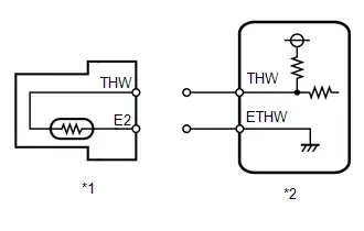
Procedure1
(b) According to the display on the GTS, read the Data List.
Powertrain > Engine > Data List| Tester Display |
|---|
| Coolant Temperature |
OK:
| GTS Display | Specified Condition |
|---|---|
| Coolant Temperature | -40°C (-40°F) |
| Result | Proceed to |
|---|---|
| The value of Coolant Temperature is -40 °C | A |
| None of the above conditions are met | B |
Post-procedure1
(c) None
| A |

| REPLACE ENGINE COOLANT TEMPERATURE SENSOR |
|

| 2. | CHECK HARNESS AND CONNECTOR (ENGINE COOLANT TEMPERATURE SENSOR - ECM) |
Pre-procedure1
(a) Disconnect the engine coolant temperature sensor connector.
(b) Disconnect the ECM connector.
Procedure1
(c) Measure the resistance according to the value(s) in the table below.
Standard Resistance:
 Click Location & Routing(C39,C53) Click Connector(C39) Click Connector(C53)
 | Tester Connection | Condition | Specified Condition | Result |
|---|---|---|---|
| C39-2 (THW) or C53-124 (THW) - Body ground and other terminals | Always | 10 kΩ or higher | kΩ |
Post-procedure1
(d) None
| OK |

| REPLACE ECM |
| NG |

| REPAIR OR REPLACE HARNESS OR CONNECTOR |
Engine Coolant Temperature Sensor 1 Circuit Short to Battery or Open (P011515)
DESCRIPTION
Refer to DTC P011511.
Click here

HINT:
When DTC P011515 is stored, the ECM enters fail-safe mode. During fail-safe mode, the engine coolant temperature is estimated to be 80°C (176°F) by the ECM. Fail-safe mode continues until a pass condition is detected.
| DTC No. | Detection Item | DTC Detection Condition | Trouble Area | MIL | DTC Output from | Priority | Note |
|---|---|---|---|---|---|---|---|
| P011515 | Engine Coolant Temperature Sensor 1 Circuit Short to Battery or Open | Diagnosis condition:
Abnormal condition:
Malfunction time:
Trip logic:
Detection conditions:
Sensors/components used for detection:
|
| Comes on | Engine | A | SAE Code: P0118 |
HINT:
When this DTC is output, check the engine coolant temperature in the Data List. Enter the following menus: Powertrain / Engine / Data List / Coolant Temperature.
| DTC No. | Coolant Temperature | Malfunction |
|---|---|---|
| P011515 | -40°C (-40°F) |
|
If the Data List value is normal it may be due to a temporary recovery from the malfunction condition. Check for intermittent problems.
Click here

MONITOR DESCRIPTION
When the ignition switch is turned ON and the output voltage of the engine coolant temperature sensor is higher than 4.91 V for 0.5 seconds or more, the ECM determines that the engine coolant temperature sensor circuit is malfunctioning and illuminates the MIL and stores a DTC.
MONITOR STRATEGY
| Frequency of Operation | Continuous |
CONFIRMATION DRIVING PATTERN
Refer to DTC P011511.
Click here

WIRING DIAGRAM
Refer to DTC P011511.
Click here

CAUTION / NOTICE / HINT
NOTICE:
-
Toyota Prius Vehicle Control History may be stored in the hybrid vehicle control ECU assembly if the engine is malfunctioning. Certain vehicle condition information is recorded when Vehicle Control History is stored. Reading the vehicle conditions recorded in both the freeze frame data and Vehicle Control History can be useful for troubleshooting.
Click here

(Select Powertrain in Health Check and then check the time stamp data.)
-
If any "Engine Malfunction" Toyota Prius Vehicle Control History item has been stored in the hybrid vehicle control ECU assembly, make sure to clear it. However, as all Vehicle Control History items are cleared simultaneously, if any Vehicle Control History items other than "Engine Malfunction" are stored, make sure to perform any troubleshooting for them before clearing Toyota Prius Vehicle Control History.
Click here

PROCEDURE
| 1. | CHECK TERMINAL VOLTAGE (ENGINE COOLANT TEMPERATURE SENSOR) |
Pre-procedure1
(a) Disconnect the engine coolant temperature sensor connector.
(b) Turn the ignition switch ON.
Procedure1
(c) Measure the voltage according to the value(s) in the table below.
Standard Voltage:
 Click Location & Routing(C39) Click Connector(C39)
 | Tester Connection | Condition | Specified Condition | Result |
|---|---|---|---|
| C39-2 (THW) - Body ground | Ignition switch ON | 0 to 5.5 V | V |
Post-procedure1
(d) None
| NG |

| GO TO STEP 4 |
|

| 2. | READ VALUE USING GTS (COOLANT TEMPERATURE) |
Pre-procedure1
(a) Disconnect the engine coolant temperature sensor connector.
(b) Connect terminals 2 (THW) and 1 (E2) of the engine coolant temperature sensor connector on the wire harness side.
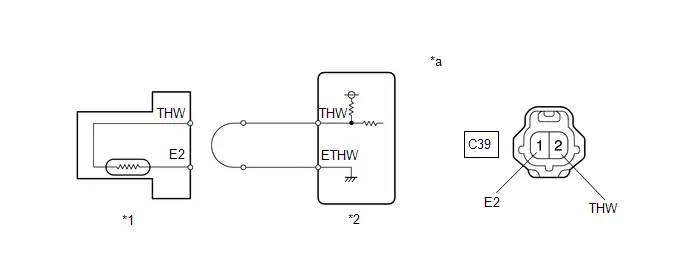
| *1 | Engine Coolant Temperature Sensor | *2 | ECM |
| *a | Front view of wire harness connector (to Engine Coolant Temperature Sensor) | - | - |
Procedure1
(c) According to the display on the GTS, read the Data List.
Powertrain > Engine > Data List| Tester Display |
|---|
| Coolant Temperature |
OK:
| GTS Display | Specified Condition |
|---|---|
| Coolant Temperature | 140°C (284°F) |
| Result | Proceed to |
|---|---|
| The value of Coolant Temperature is more than 140 °C | A |
| None of the above conditions are met | B |
Post-procedure1
(d) None
| A |

| REPLACE ENGINE COOLANT TEMPERATURE SENSOR |
|

| 3. | CHECK HARNESS AND CONNECTOR (ENGINE COOLANT TEMPERATURE SENSOR - ECM) |
Pre-procedure1
(a) Disconnect the engine coolant temperature sensor connector.
(b) Disconnect the ECM connector.
Procedure1
(c) Measure the resistance according to the value(s) in the table below.
Standard Resistance:
 Click Location & Routing(C39,C53) Click Connector(C39) Click Connector(C53)
 | Tester Connection | Condition | Specified Condition | Result |
|---|---|---|---|
| C39-2 (THW) - C53-124 (THW) | Always | Below 1 Ω | Ω |
| C39-1 (E2) - C53-123 (ETHW) | Always | Below 1 Ω | Ω |
Post-procedure1
(d) None
| OK |

| REPLACE ECM |
| NG |

| REPAIR OR REPLACE HARNESS OR CONNECTOR |
| 4. | CHECK HARNESS AND CONNECTOR (ENGINE COOLANT TEMPERATURE SENSOR - ECM) |
Pre-procedure1
(a) Disconnect the engine coolant temperature sensor connector.
(b) Disconnect the ECM connector.
Procedure1
(c) Measure the resistance according to the value(s) in the table below.
Standard Resistance:
 Click Location & Routing(C39,C53) Click Connector(C39) Click Connector(C53)
 | Tester Connection | Condition | Specified Condition | Result |
|---|---|---|---|
| C39-2 (THW) or C53-124 (THW) - Other terminals | Always | 10 kΩ or higher | kΩ |
Post-procedure1
(d) None
| OK |

| REPLACE ECM |
| NG |

| REPAIR OR REPLACE HARNESS OR CONNECTOR |
Engine Coolant Temperature Sensor 1 Signal Stuck in Range (P01152A)
DESCRIPTION
Refer to DTC P011511.
Click here

| DTC No. | Detection Item | DTC Detection Condition | Trouble Area | MIL | DTC Output from | Priority | Note |
|---|---|---|---|---|---|---|---|
| P01152A | Engine Coolant Temperature Sensor 1 Signal Stuck in Range | Either of the following conditions is met (2 trip detection logic):
|
| Comes on | Engine | B | SAE Code: P0116 |
MONITOR DESCRIPTION
Engine Coolant Temperature Sensor Cold Start MonitorWhen a cold engine start is performed and then the engine is warmed up, if the engine coolant temperature sensor value does not change, it is determined that a malfunction has occurred. If this is detected in 2 consecutive driving cycles, the MIL is illuminated and this DTC is stored.
Engine Coolant Temperature Sensor Soak MonitorIf the engine coolant temperature sensor value does not change after the warmed up engine is stopped and then the next cold engine start is performed, it is determined that a malfunction has occurred. If this is detected in 2 consecutive driving cycles, the MIL is illuminated and this DTC is stored.
MONITOR STRATEGY
| Required Sensors/Components | Engine coolant temperature sensor |
| Frequency of Operation | Once per driving cycle |
CONFIRMATION DRIVING PATTERN

- Enter the following menus: Powertrain / Engine / Data List / Coolant Temperature.
- Check that the engine coolant temperature is 60°C (140°F) or less.
- Clear the DTCs (even if no DTCs are stored, perform the clear DTC procedure).
- Turn the ignition switch off and wait for at least 30 seconds.
- Turn the ignition switch ON [A].
-
Put the engine in Inspection Mode (Maintenance Mode).
Click here

-
Start the engine and idle it for 5 minutes or more [B].
HINT:
If the engine coolant temperature does not change by 5°C (9°F) or higher, the engine coolant temperature sensor is malfunctioning. It is not necessary to continue this procedure.
- Enter the following menus: Powertrain / Engine / Trouble Codes [C].
-
Read the pending DTCs.
HINT:
- If a pending DTC is output, the system is malfunctioning.
- If a pending DTC is not output, perform the following procedure.
- Enter the following menus: Powertrain / Engine / Utility / All Readiness.
- Input the DTC: P01152A.
-
Check the DTC judgment result.
HINT:
- If the judgment result is NORMAL, the system is normal.
- If the judgment result is ABNORMAL, the system is malfunctioning.
- If the judgment result is INCOMPLETE, perform steps [D] and [E].
-
With the engine running, drive the Toyota Prius vehicle at 40 km/h (25 mph) or more for a total of 5 minutes or more [D].
CAUTION:
When performing the confirmation driving pattern, obey all speed limits and traffic laws.
HINT:
- In the event of the drive pattern being interrupted (possibly due to factors such as traffic conditions), the drive pattern can be resumed.
- If the engine stops, further depress the accelerator pedal to restart the engine.
-
Check the DTC judgment result again [E].
HINT:
If the judgment result is INCOMPLETE, perform steps [D] and [E] again.
CAUTION / NOTICE / HINT
NOTICE:
-
Toyota Prius Vehicle Control History may be stored in the hybrid vehicle control ECU assembly if the engine is malfunctioning. Certain vehicle condition information is recorded when Vehicle Control History is stored. Reading the vehicle conditions recorded in both the freeze frame data and Vehicle Control History can be useful for troubleshooting.
Click here

(Select Powertrain in Health Check and then check the time stamp data.)
-
If any "Engine Malfunction" Toyota Prius Vehicle Control History item has been stored in the hybrid vehicle control ECU assembly, make sure to clear it. However, as all Vehicle Control History items are cleared simultaneously, if any Vehicle Control History items other than "Engine Malfunction" are stored, make sure to perform any troubleshooting for them before clearing Toyota Prius Vehicle Control History.
Click here

HINT:
- If any of DTCs P011511 or P011515 are output simultaneously with DTC P01152A, the engine coolant temperature sensor may have an open or a short circuit. Troubleshoot those DTCs first.
- When this DTC is output, check the engine coolant temperature using the GTS. Enter the following menus: Powertrain / Engine / Data List / Coolant Temperature. If the value of Coolant Temperature is lower than the actual engine coolant temperature, the engine coolant temperature sensor circuit may be malfunctioning. In this case, check the wire harnesses and connectors (and their connection condition) between the ECM and the engine coolant temperature sensor first.
PROCEDURE
| 1. | CHECK ANY OTHER DTCS OUTPUT (IN ADDITION TO DTC P01152A) |
(a) Read the DTCs.
Powertrain > Engine > Trouble Codes| Result | Proceed to |
|---|---|
| P01152A and other DTCs are output | A |
| P01152A is output | B |
HINT:
If any DTCs other than P01152A are output, troubleshoot those DTCs first.
| A |

| GO TO DTC CHART |
|

| 2. | INSPECT WATER INLET WITH THERMOSTAT SUB-ASSEMBLY |
Click here

| OK |

| REPLACE ENGINE COOLANT TEMPERATURE SENSOR |
| NG |

| REPLACE WATER INLET WITH THERMOSTAT SUB-ASSEMBLY |
Throttle / Pedal Position Sensor / Switch "A" Circuit Short to Ground (P012011)
DESCRIPTION
The throttle position sensor is built into the throttle body assembly and detects the opening angle of the throttle valve. This sensor is a non-contact type sensor. It uses Hall-effect elements in order to yield accurate signals even in extreme driving conditions, such as at high speeds as well as very low speeds.
The throttle position sensor has 2 sensor circuits, VTA1 and VTA2, each of which transmits a signal. VTA1 is used to detect the throttle valve angle and VTA2 is used to detect malfunctions in VTA1. The sensor signal voltages vary between 0 V and 5 V in proportion to the throttle valve opening angle, and are transmitted to the VTA1 and VTA2 terminals of the ECM.
As the valve closes, the sensor output voltage decreases and as the valve opens, the sensor output voltage increases. The ECM calculates the throttle valve opening angle according to these signals and controls the throttle actuator in response to a request from the hybrid system. These signals are also used in calculations such as air fuel ratio correction, power increase correction and fuel-cut control.
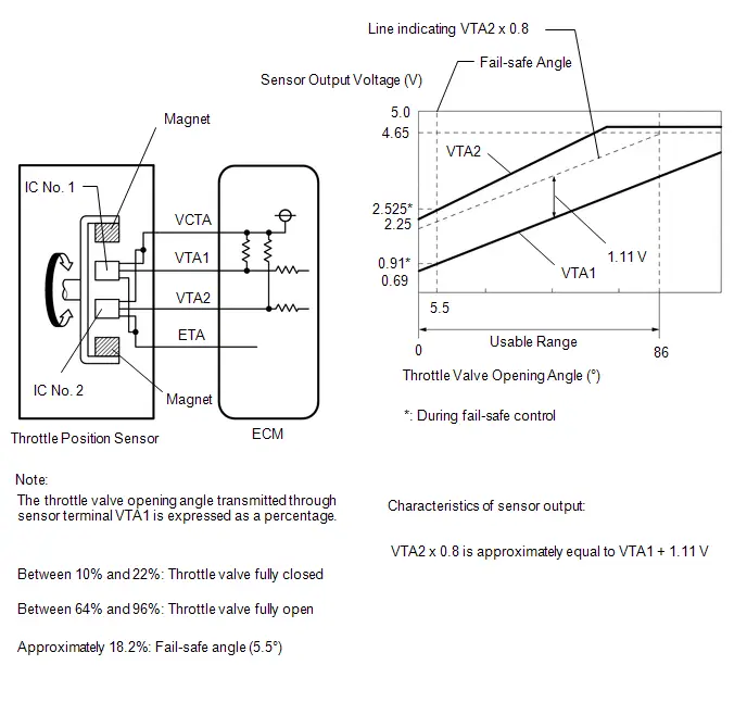
HINT:
- When throttle position sensor DTCs are output, check the throttle valve opening angle using the GTS. Enter the following menus: Powertrain / Engine / Data List / Throttle Position Sensor No.1 Voltage and Throttle Position Sensor No.2 Voltage.
-
Throttle Position Sensor No.1 Voltage is the VTA1 signal, and Throttle Position Sensor No.2 Voltage is the VTA2 signal.
Reference (Normal Condition):
GTS Display
Accelerator Pedal Fully Released
Throttle Position Sensor No.1 Voltage
0.6 to 1.1 V
Throttle Position Sensor No.2 Voltage
2.1 to 3.1 V
| DTC No. | Detection Item | DTC Detection Condition | Trouble Area | MIL | DTC Output from | Priority | Note |
|---|---|---|---|---|---|---|---|
| P012011 | Throttle / Pedal Position Sensor / Switch "A" Circuit Short to Ground | The output voltage of VTA1 is less than 0.56 V for 2 seconds or more (1 trip detection logic). |
| Comes on | Engine | A | SAE Code: P0122 |
MONITOR DESCRIPTION
The ECM uses the throttle position sensor to monitor the throttle valve opening angle. If the VTA1 terminal voltage is less than the threshold, the ECM will illuminate the MIL and store this DTC.
MONITOR STRATEGY
| Frequency of Operation | Continuous |
CONFIRMATION DRIVING PATTERN

- Clear the DTCs (even if no DTCs are stored, perform the clear DTC procedure).
- Turn the ignition switch off and wait for at least 30 seconds.
- Turn the ignition switch ON [A].
-
Put the engine in Inspection Mode (Maintenance Mode).
Click here

- Start the engine.
-
With the Toyota Prius vehicle stationary, fully depress and release the accelerator pedal [B].
HINT:
During charge control, the engine speed is set at idle. Therefore, the engine speed will not increase when the accelerator pedal is depressed. In this case, perform step [B] after charge control has completed.
- Idle the engine for 2 seconds or more [C].
- Enter the following menus: Powertrain / Engine / Trouble Codes [D].
-
Read the pending DTCs.
HINT:
- If a pending DTC is output, the system is malfunctioning.
- If a pending DTC is not output, perform the following procedure.
- Enter the following menus: Powertrain / Engine / Utility / All Readiness.
- Input the DTC: P012011.
-
Check the DTC judgment result.
HINT:
- If the judgment result is NORMAL, the system is normal.
- If the judgment result is ABNORMAL, the system is malfunctioning.
- If the judgment result is INCOMPLETE, perform steps [B] through [D] again.
FAIL-SAFE
When this DTC is stored, the ECM enters fail-safe mode. During fail-safe mode, the ECM cuts the current to the throttle actuator, and the throttle valve is returned to a 5.5° throttle valve opening angle by the return spring. The ECM then adjusts the engine output, by controlling the fuel injection (intermittent fuel cut) and ignition timing, in accordance with the engine torque request signal sent from the hybrid Toyota Prius vehicle control ECU, to allow the vehicle to continue being driven at a minimal speed. If the accelerator pedal is depressed firmly and gently, the vehicle can be driven slowly.
Fail-safe mode continues until a pass condition is detected, and the ignition switch is turned off.
WIRING DIAGRAM
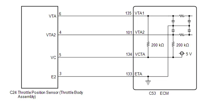
CAUTION / NOTICE / HINT
NOTICE:
-
Toyota Prius Vehicle Control History may be stored in the hybrid vehicle control ECU if the engine is malfunctioning. Certain vehicle condition information is recorded when Vehicle Control History is stored. Reading the vehicle conditions recorded in both the freeze frame data and Vehicle Control History can be useful for troubleshooting.
Click here

(Select Powertrain in Health Check and then check the time stamp data.)
-
If any "Engine Malfunction" Toyota Prius Vehicle Control History item has been stored in the hybrid vehicle control ECU, make sure to clear it. However, as all Vehicle Control History items are cleared simultaneously, if any Vehicle Control History items other than "Engine Malfunction" are stored, make sure to perform any troubleshooting for them before clearing Toyota Prius Vehicle Control History.
Click here

PROCEDURE
| 1. | READ VALUE USING GTS (THROTTLE POSITION SENSOR NO.1 VOLTAGE) |
Pre-procedure1
(a) Read the values displayed on the GTS.
Powertrain > Engine > Data List| Tester Display |
|---|
| Throttle Position Sensor No.1 Voltage |
(b) Disconnect the throttle body assembly connector.
Procedure1
(c) Compare the value of the Data List item Throttle Position Sensor No. 1 Voltage after disconnecting the throttle body assembly connector to the value when the connector was connected.
| Result | Proceed to |
|---|---|
| Changes from less than 0.56 V to higher than 4.535 V | A |
| Does not change from less than 0.56 V | B |
Post-procedure1
(d) None
| A |

| REPLACE THROTTLE BODY ASSEMBLY |
|

| 2. | CHECK HARNESS AND CONNECTOR (THROTTLE POSITION SENSOR - ECM) |
Pre-procedure1
(a) Disconnect the throttle body assembly connector.
(b) Disconnect the ECM connector.
Procedure1
(c) Measure the resistance according to the value(s) in the table below.
Standard Resistance:
 Click Location & Routing(C24,C53) Click Connector(C24) Click Connector(C53)
 | Tester Connection | Condition | Specified Condition | Result |
|---|---|---|---|
| C24-5 (VC) - C53-134 (VCTA) | Always | Below 1 Ω | Ω |
| C24-6 (VTA) or C53-135 (VTA1) - Body ground and other terminals | Always | 10 kΩ or higher | kΩ |
Post-procedure1
(d) None
| OK |

| REPLACE ECM |
| NG |

| REPAIR OR REPLACE HARNESS OR CONNECTOR |
Throttle / Pedal Position Sensor / Switch "A" Circuit Short to Battery or Open (P012015)
DESCRIPTION
Refer to DTC P012011.
Click here

| DTC No. | Detection Item | DTC Detection Condition | Trouble Area | MIL | DTC Output from | Priority | Note |
|---|---|---|---|---|---|---|---|
| P012015 | Throttle / Pedal Position Sensor / Switch "A" Circuit Short to Battery or Open | The output voltage of VTA1 is higher than 4.535 V for 2 seconds or more (1 trip detection logic). |
| Comes on | Engine | A | SAE Code: P0123 |
MONITOR DESCRIPTION
The ECM uses the throttle position sensor to monitor the throttle valve opening angle. If the VTA1 terminal voltage is higher than the threshold, the ECM will illuminate the MIL and store this DTC.
MONITOR STRATEGY
| Frequency of Operation | Continuous |
CONFIRMATION DRIVING PATTERN

- Clear the DTCs (even if no DTCs are stored, perform the clear DTC procedure).
- Turn the ignition switch off and wait for at least 30 seconds.
- Turn the ignition switch ON [A].
-
Put the engine in Inspection Mode (Maintenance Mode).
Click here

- Start the engine.
-
With the Toyota Prius vehicle stationary, fully depress and release the accelerator pedal [B].
HINT:
During charge control, the engine speed is set at idle. Therefore, the engine speed will not increase when the accelerator pedal is depressed. In this case, perform step [B] after charge control has completed.
- Idle the engine for 2 seconds or more [C].
- Enter the following menus: Powertrain / Engine / Trouble Codes [D].
-
Read the pending DTCs.
HINT:
- If a pending DTC is output, the system is malfunctioning.
- If a pending DTC is not output, perform the following procedure.
- Enter the following menus: Powertrain / Engine / Utility / All Readiness.
- Input the DTC: P012015.
-
Check the DTC judgment result.
HINT:
- If the judgment result is NORMAL, the system is normal.
- If the judgment result is ABNORMAL, the system is malfunctioning.
- If the judgment result is INCOMPLETE, perform steps [B] through [D] again.
FAIL-SAFE
When this DTC is stored, the ECM enters fail-safe mode. During fail-safe mode, the ECM cuts the current to the throttle actuator, and the throttle valve is returned to a 5.5° throttle valve opening angle by the return spring. The ECM then adjusts the engine output, by controlling the fuel injection (intermittent fuel cut) and ignition timing, in accordance with the engine torque request signal sent from the hybrid Toyota Prius vehicle control ECU, to allow the vehicle to continue being driven at a minimal speed. If the accelerator pedal is depressed firmly and gently, the vehicle can be driven slowly.
Fail-safe mode continues until a pass condition is detected, and the ignition switch is turned off.
WIRING DIAGRAM
Refer to DTC P012011.
Click here

CAUTION / NOTICE / HINT
NOTICE:
-
Toyota Prius Vehicle Control History may be stored in the hybrid vehicle control ECU if the engine is malfunctioning. Certain vehicle condition information is recorded when Vehicle Control History is stored. Reading the vehicle conditions recorded in both the freeze frame data and Vehicle Control History can be useful for troubleshooting.
Click here

(Select Powertrain in Health Check and then check the time stamp data.)
-
If any "Engine Malfunction" Toyota Prius Vehicle Control History item has been stored in the hybrid vehicle control ECU, make sure to clear it. However, as all Vehicle Control History items are cleared simultaneously, if any Vehicle Control History items other than "Engine Malfunction" are stored, make sure to perform any troubleshooting for them before clearing Toyota Prius Vehicle Control History.
Click here

PROCEDURE
| 1. | CHECK HARNESS AND CONNECTOR (THROTTLE POSITION SENSOR - ECM) |
Pre-procedure1
(a) Disconnect the throttle body assembly connector.
(b) Disconnect the ECM connector.
Procedure1
(c) Measure the resistance according to the value(s) in the table below.
Standard Resistance:
 Click Location & Routing(C24,C53) Click Connector(C24) Click Connector(C53)
 | Tester Connection | Condition | Specified Condition | Result |
|---|---|---|---|
| C24-6 (VTA) - C53-135 (VTA1) | Always | Below 1 Ω | Ω |
| C24-3 (E2) - C53-133 (ETA) | Always | Below 1 Ω | Ω |
| C24-5 (VC) or C53-134 (VCTA) - Body ground and other terminals | Always | 10 kΩ or higher | kΩ |
| C24-6 (VTA) or C53-135 (VTA1) - Body ground and other terminals | Always | 10 kΩ or higher | kΩ |
Post-procedure1
(d) None
| NG |

| REPAIR OR REPLACE HARNESS OR CONNECTOR |
|

| 2. | CHECK TERMINAL VOLTAGE (POWER SOURCE OF THROTTLE POSITION SENSOR) |
Pre-procedure1
(a) Disconnect the throttle body assembly connector.
(b) Turn the ignition switch ON.
Procedure1
(c) Measure the voltage according to the value(s) in the table below.
Standard Voltage:
 Click Location & Routing(C24) Click Connector(C24)
 | Tester Connection | Condition | Specified Condition | Result |
|---|---|---|---|
| C24-5 (VC) - C24-3 (E2) | Ignition switch ON | 4.5 to 5.5 V | V |
| C24-6 (VTA) - C24-3 (E2) | Ignition switch ON | 3.0 to 5.0 V | V |
Post-procedure1
(d) None
| NG |

| REPLACE ECM |
|

| 3. | CHECK HARNESS AND CONNECTOR (RESISTANCE OF ECM) |
Pre-procedure1
(a) Disconnect the throttle body assembly connector.
Procedure1
(b) Measure the resistance according to the value(s) in the table below.
Standard Resistance:
 Click Location & Routing(C24) Click Connector(C24)
 | Tester Connection | Condition | Specified Condition | Result |
|---|---|---|---|
| C24-5 (VC) - C24-6 (VTA) | Ignition switch off | 190 to 210 kΩ | kΩ |
Post-procedure1
(c) None
| NG |

| REPLACE ECM |
|

| 4. | READ VALUE USING GTS (THROTTLE POSITION SENSOR NO.1 VOLTAGE) |
Pre-procedure1
(a) Disconnect the throttle body assembly connector.
Procedure1
(b) According to the display on the GTS, read the Data List.
Powertrain > Engine > Data List| Tester Display |
|---|
| Throttle Position Sensor No.1 Voltage |
HINT:
Use the snapshot function to record the value displayed or make a note of it.
Post-procedure1
(c) Turn the ignition switch off.
Pre-procedure2
(d) Connect terminals 3 (E2) and 6 (VTA) of the throttle body assembly connector on the wire harness side.
NOTICE:
If the VTA terminal voltage or the resistance between VTA and E2 is abnormal and terminals 3 (E2) and 6 (VTA) of the throttle body assembly connector are connected, excessive current may flow through the circuit. In this case, do not connect the terminals.
Procedure2
(e) Compare the Toyota Prius vehicle of the Data List item Throttle Position Sensor No.1 Voltage after the circuit is shorted to the value when the throttle body assembly connector was connected.
| Result | Proceed to |
|---|---|
| Changes from higher than 4.535 V to less than 0.56 V | A |
| Does not change from higher than 4.535 V | B |
Post-procedure2
(f) None
| A |

| REPLACE THROTTLE BODY ASSEMBLY |
| B |

| REPLACE ECM |
Throttle / Pedal Position Sensor / Switch "A" Circuit Voltage Out of Range (P01201C)
DESCRIPTION
Refer to DTC P012011.
Click here

| DTC No. | Detection Item | DTC Detection Condition | Trouble Area | MIL | DTC Output from | Priority | Note |
|---|---|---|---|---|---|---|---|
| P01201C | Throttle / Pedal Position Sensor / Switch "A" Circuit Voltage Out of Range | The difference between the output voltage of VTA1 and VTA2 is less than 0.8 V, or higher than 1.6 V for 2 seconds or more (1 trip detection logic). |
| Comes on | Engine | A | SAE Code: P0121 |
MONITOR DESCRIPTION
The ECM uses the throttle position sensor to monitor the throttle valve opening angle. There are several checks that the ECM performs to confirm the proper operation of the throttle position sensor.
This sensor transmits two signals: VTA1 and VTA2. VTA1 is used to detect the throttle opening angle and VTA2 is used to detect malfunctions in VTA1. The ECM performs several checks to confirm the proper operation of the throttle position sensor and VTA1.
For each throttle opening angle, a specific voltage difference is expected between the outputs of VTA1 and VTA2. If the output voltage difference between the two signals deviates from the normal operating range, the ECM interprets this as a malfunction of the throttle position sensor, illuminates the MIL and stores a DTC.
MONITOR STRATEGY
| Frequency of Operation | Continuous |
CONFIRMATION DRIVING PATTERN
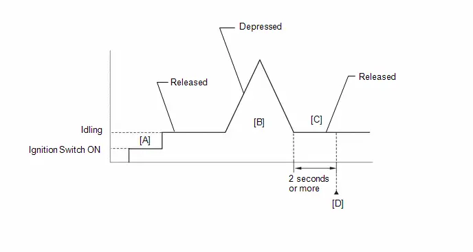
- Clear the DTCs (even if no DTCs are stored, perform the clear DTC procedure).
- Turn the ignition switch off and wait for at least 30 seconds.
- Turn the ignition switch ON [A].
-
Put the engine in Inspection Mode (Maintenance Mode).
Click here

- Start the engine.
-
With the Toyota Prius vehicle stationary, fully depress and release the accelerator pedal [B].
HINT:
During charge control, the engine speed is set at idle. Therefore, the engine speed will not increase when the accelerator pedal is depressed. In this case, perform step [B] after charge control has completed.
- Idle the engine for 2 seconds or more [C].
- Enter the following menus: Powertrain / Engine / Trouble Codes [D].
-
Read the pending DTCs.
HINT:
- If a pending DTC is output, the system is malfunctioning.
- If a pending DTC is not output, perform the following procedure.
- Enter the following menus: Powertrain / Engine / Utility / All Readiness.
- Input the DTC: P01201C.
-
Check the DTC judgment result.
HINT:
- If the judgment result is NORMAL, the system is normal.
- If the judgment result is ABNORMAL, the system is malfunctioning.
- If the judgment result is INCOMPLETE, perform steps [B] through [D] again.
FAIL-SAFE
When this DTC is stored, the ECM enters fail-safe mode. During fail-safe mode, the ECM cuts the current to the throttle actuator, and the throttle valve is returned to a 5.5° throttle valve opening angle by the return spring. The ECM then adjusts the engine output, by controlling the fuel injection (intermittent fuel cut) and ignition timing, in accordance with the engine torque request signal sent from the hybrid Toyota Prius vehicle control ECU, to allow the vehicle to continue being driven at a minimal speed. If the accelerator pedal is depressed firmly and gently, the vehicle can be driven slowly.
Fail-safe mode continues until a pass condition is detected, and the ignition switch is turned off.
WIRING DIAGRAM
Refer to DTC P012011.
Click here

CAUTION / NOTICE / HINT
NOTICE:
-
Toyota Prius Vehicle Control History may be stored in the hybrid vehicle control ECU if the engine is malfunctioning. Certain vehicle condition information is recorded when Vehicle Control History is stored. Reading the vehicle conditions recorded in both the freeze frame data and Vehicle Control History can be useful for troubleshooting.
Click here

(Select Powertrain in Health Check and then check the time stamp data.)
-
If any "Engine Malfunction" Toyota Prius Vehicle Control History item has been stored in the hybrid vehicle control ECU, make sure to clear it. However, as all Vehicle Control History items are cleared simultaneously, if any Vehicle Control History items other than "Engine Malfunction" are stored, make sure to perform any troubleshooting for them before clearing Toyota Prius Vehicle Control History.
Click here

HINT:
-
DTC P01201C is stored when the VTA1 and VTA2 output voltages are not consistent with the sensor characteristics. Therefore, check the freeze frame data for this DTC. Use the following formula to confirm the relative differences in voltage.
Characteristic Sensor Output:
VTA2 x 0.8 is approximately equal to VTA1 1.11 V
VTA1: Throttle Position Sensor No.1 Voltage
VTA2: Throttle Position Sensor No.2 Voltage
PROCEDURE
| 1. | CHECK HARNESS AND CONNECTOR (THROTTLE POSITION SENSOR - ECM) |
Pre-procedure1
(a) Disconnect the throttle body assembly connector.
(b) Disconnect the ECM connector.
Procedure1
(c) Measure the resistance according to the value(s) in the table below.
Standard Resistance:
 Click Location & Routing(C24,C53) Click Connector(C24) Click Connector(C53)
 | Tester Connection | Condition | Specified Condition | Result |
|---|---|---|---|
| C24-5 (VC) - C53-134 (VCTA) | Always | Below 1 Ω | Ω |
| C24-6 (VTA) - C53-135 (VTA1) | Always | Below 1 Ω | Ω |
| C24-4 (VTA2) - C53-101 (VTA2) | Always | Below 1 Ω | Ω |
| C24-3 (E2) - C53-133 (ETA) | Always | Below 1 Ω | Ω |
| C24-5 (VC) or C53-134 (VCTA) - Body ground and other terminals | Always | 10 kΩ or higher | kΩ |
| C24-6 (VTA) or C53-135 (VTA1) - Body ground and other terminals | Always | 10 kΩ or higher | kΩ |
| C24-4 (VTA2) or C53-101 (VTA2) - Body ground and other terminals | Always | 10 kΩ or higher | kΩ |
(d) Inspect the condition of the terminals of the connectors.
HINT:
Click here

Post-procedure1
(e) None
| OK |

| GO TO STEP 5 |
|

| 2. | REPAIR OR REPLACE HARNESS OR CONNECTOR |
(a) Repair or replace the wire harness or connector.
|

| 3. | CLEAR DTC |
Pre-procedure1
(a) None
Procedure1
(b) Clear the DTCs.
Powertrain > Engine > Clear DTCsPost-procedure1
(c) Turn the ignition switch off and wait for at least 30 seconds.
|

| 4. | CHECK WHETHER DTC OUTPUT RECURS (DTC P01201C) |
Pre-procedure1
(a) Drive the Toyota Prius vehicle in accordance with the driving pattern described in Confirmation Driving Pattern.
Procedure1
(b) Read the DTCs.
Powertrain > Engine > Trouble Codes| Result | Proceed to |
|---|---|
| DTCs are not output | A |
| P01201C is output | B |
Post-procedure1
(c) None
| A |

| END |
|

| 5. | CHECK HARNESS AND CONNECTOR (RESISTANCE OF ECM) |
Pre-procedure1
(a) Disconnect the throttle body assembly connector.
Procedure1
(b) Measure the resistance according to the value(s) in the table below.
Standard Resistance:
 Click Location & Routing(C24) Click Connector(C24)
 | Tester Connection | Condition | Specified Condition | Result |
|---|---|---|---|
| C24-5 (VC) - C24-6 (VTA) | Ignition switch off | 190 to 210 kΩ | kΩ |
| C24-5 (VC) - C24-4 (VTA2) | Ignition switch off | 190 to 210 kΩ | kΩ |
Post-procedure1
(c) None
| OK |

| REPLACE THROTTLE BODY ASSEMBLY |
| NG |

| REPLACE ECM |
O2 Sensor Circuit Bank 1 Sensor 2 Circuit Open (P013613,P013617,P01361C)
DESCRIPTION
Refer to DTC P003612.
Click here

| DTC No. | Detection Item | DTC Detection Condition | Trouble Area | MIL | DTC Output from | Priority | Note |
|---|---|---|---|---|---|---|---|
| P013613 | O2 Sensor Circuit Bank 1 Sensor 2 Circuit Open | Abnormal output voltage:
|
| Comes on | Engine | B | SAE Code: P0136 |
| P013617 | O2 Sensor Circuit Bank 1 Sensor 2 Circuit Voltage Above Threshold | Low voltage (open):
|
| Comes on | Engine | B | SAE Code: P0137 |
| P01361C | O2 Sensor Circuit Bank 1 Sensor 2 Circuit Voltage Out of Range | High voltage (short):
|
| Comes on | Engine | B | SAE Code: P0138 |
MONITOR DESCRIPTION
Active Air fuel Ratio Control
The ECM usually performs air fuel ratio feedback control so that the air fuel ratio sensor output indicates a near stoichiometric air fuel ratio. This Toyota Prius vehicle includes active air fuel ratio control in addition to regular air fuel ratio control. The ECM performs active air fuel ratio control to detect any deterioration in the Three-Way Catalytic Converter (TWC) and any malfunctions of the heated oxygen sensor (refer to the diagram below).
Active air fuel ratio control is performed for approximately 30 seconds while driving with a warm engine. During active air fuel ratio control, the air fuel ratio is forcibly regulated to become lean or rich by the ECM. If the ECM detects a malfunction, a DTC is stored.
Abnormal Heated Oxygen Sensor Output Voltage (DTC P013613)
While the ECM is performing active air fuel ratio control, the air fuel ratio is forcibly regulated to become rich or lean. If the sensor is not functioning properly, the variation in output voltage is small. For example, when the heated oxygen sensor voltage does not increase to 0.71 V or higher during active air fuel ratio control, the ECM determines that the sensor output voltage is abnormal and stores DTC P013613.

Open or Short in Heated Oxygen Sensor Circuit (DTC P013617 or P01361C)
During active air fuel ratio control, the ECM calculates the Oxygen Storage Capacity (OSC)* of the Three-Way Catalytic Converter (TWC) by forcibly regulating the air fuel ratio to become rich or lean.
If the heated oxygen sensor has an open circuit, or the output voltage of the sensor noticeably decreases, the OSC will be an extremely high value. Even if the ECM attempts to continue regulating the air fuel ratio to become rich or lean, the heated oxygen sensor output will not change.
While performing active air fuel ratio control, when the target air fuel ratio is rich and the heated oxygen sensor output voltage is less than 0.21 V (lean), the ECM interprets this as an abnormally low sensor output voltage and stores DTC P013617.
When the target air fuel ratio is lean and the output voltage is higher than 0.71 V (rich) during active air fuel ratio control, the ECM determines that the sensor output voltage is abnormally high and stores DTC P01361C.
HINT:
*: The TWC has the capability to store oxygen. The OSC and the emission purification capacity of the TWC are mutually related. The ECM determines whether the catalyst has deteriorated based on the calculated OSC value.
Click here

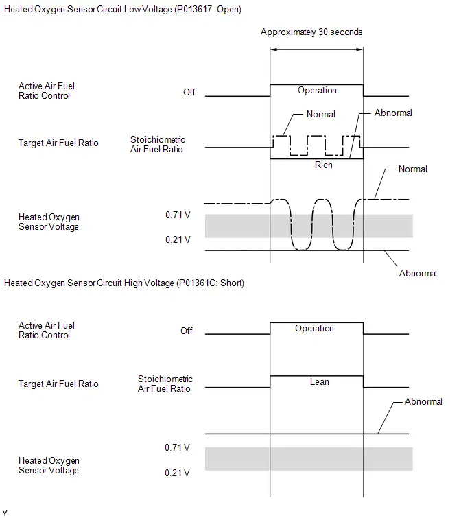
MONITOR STRATEGY
| Required Sensors/Components (Main) | Heated oxygen sensor (sensor 2) |
| Required Sensors/Components (Related) | Crankshaft position sensor Engine coolant temperature sensor Mass air flow meter sub-assembly Throttle position sensor Air fuel ratio sensor |
| Frequency of Operation | Once per driving cycle |
TYPICAL ENABLING CONDITIONS
Heated Oxygen Sensor Voltage Check (Voltage Malfunction, High Voltage and Low Voltage)| Active air fuel ratio control | Executing |
| Active air fuel ratio control begins when all of following conditions met: | - |
| Auxiliary battery voltage | 11 V or higher |
| Engine coolant temperature | 75°C (167°F) or higher |
| Idling | Off |
| Engine speed | Less than 4000 rpm |
| Air fuel ratio sensor status | Activated |
| Fuel system status | Closed loop |
| Engine load | 10% or higher, and less than 70% |
TYPICAL MALFUNCTION THRESHOLDS
P013613: Heated Oxygen Sensor Voltage Check (Voltage Malfunction)| Either of following conditions is met | 1 or 2 |
| 1. Both of following conditions are met | - |
| (a) Commanded air fuel ratio | 14.4 or less |
| (b) Heated oxygen sensor voltage | 0.21 V or higher, and less than 0.71 V |
| 2. Both of following conditions are met | - |
| (c) Commanded air fuel ratio | 14.8 or more |
| (d) Heated oxygen sensor voltage | 0.21 V or higher, and less than 0.71 V |
| Both of following conditions are met | - |
| (a) Commanded air fuel ratio | 14.4 or less |
| (b) Heated oxygen sensor voltage | Less than 0.21 V |
| Both of following conditions are met | - |
| (a) Commanded air fuel ratio | 14.8 or more |
| (b) Heated oxygen sensor voltage | Higher than 0.71 V |
CONFIRMATION DRIVING PATTERN
HINT:
- This confirmation driving pattern is used for the "Perform Confirmation Driving Pattern" procedure of the following diagnostic troubleshooting procedure.
- Performing this confirmation driving pattern will activate the heated oxygen sensor monitor (the catalyst monitor is performed simultaneously). This is very useful for verifying the completion of a repair.

- Clear the DTCs (even if no DTCs are stored, perform the clear DTC procedure).
- Turn the ignition switch off and wait for at least 30 seconds.
- Turn the ignition switch ON [A].
-
Put the engine in Inspection Mode (Maintenance Mode).
Click here

- Start the engine and warm it up until the engine coolant temperature is 75°C (167°F) or higher [B].
-
With the engine running, drive the Toyota Prius vehicle at 75 to 120 km/h (46 to 75 mph) for 10 minutes or more [C].
CAUTION:
When performing the confirmation driving pattern, obey all speed limits and traffic laws.
HINT:
If the engine stops, further depress the accelerator pedal to restart the engine.
- Enter the following menus: Powertrain / Engine / Trouble Codes [D].
-
Read the pending DTCs.
HINT:
- If a pending DTC is output, the system is malfunctioning.
- If a pending DTC is not output, perform the following procedure.
- Enter the following menus: Powertrain / Engine / Utility / All Readiness.
- Input the DTC: P013613, P013617 or P01361C.
-
Check the DTC judgment result.
HINT:
- If the judgment result is NORMAL, the system is normal.
- If the judgment result is ABNORMAL, the system is malfunctioning.
- If the judgment result is INCOMPLETE, perform steps [C] and [D] again.
WIRING DIAGRAM
Refer to DTC P003612.
Click here

CAUTION / NOTICE / HINT
HINT:
Malfunctioning areas can be identified by performing the Active Test "Control the Injection Volume for A/F Sensor". This Active Test can help to determine whether the air fuel ratio sensor, heated oxygen sensor and other potential trouble areas are malfunctioning.
The following procedure describes how to perform the Active Test "Control the Injection Volume for A/F Sensor" using the GTS.
-
Put the engine in Inspection Mode (Maintenance Mode).
Click here

- Start the engine and warm it up until the engine coolant temperature is 75°C (167°F) or higher.
- Idle the engine for 5 minutes or more with park (P) selected.
- Enter the following menus: Powertrain / Engine / Active Test / Control the Injection Volume for A/F Sensor / Data List / A/F (O2) Sensor Current B1S1 and O2 Sensor Voltage B1S2.
- Perform the Active Test with the engine idling (change the fuel injection volume).
- Monitor the output voltage of the air fuel ratio sensor (A/F (O2) Sensor Current B1S1) and heated oxygen sensor (O2 Sensor Voltage B1S2) displayed on the GTS.
HINT:
- The Active Test "Control the Injection Volume for A/F Sensor" can be used to lower the fuel injection volume by 12.5% or increase the injection volume by 12.5%.
- Each sensor reacts in accordance with the increases and decreases in the fuel injection volume.
Standard:
| GTS Display (Sensor) | Injection Volume | Status | Voltage |
|---|---|---|---|
| A/F (O2) Sensor Current B1S1 (Air fuel ratio) | 12.5% | Rich | Below -0.075 mA |
| -12.5% | Lean | Higher than 0.037 mA | |
| O2 Sensor Voltage B1S2 (Heated oxygen) | 12.5% | Rich | Higher than 0.55 V |
| -12.5% | Lean | Below 0.4 V |
NOTICE:
The air fuel ratio sensor has an output delay of a few seconds and the heated oxygen sensor has a maximum output delay of approximately 20 seconds.

- Performing the Active Test "Control the Injection Volume for A/F Sensor" allows the output voltage of the air fuel ratio sensor and heated oxygen sensor to be checked and graphed.
- To display the graph, enter the following menus: Powertrain / Engine / Active Test / Control the Injection Volume for A/F Sensor / Data List / A/F (O2) Sensor Voltage B1S1 and O2 Sensor Voltage B1S2; and then press the graph button on the Data List view.
NOTICE:
- Inspect the fuses for circuits related to this system before performing the following procedure.
-
Toyota Prius Vehicle Control History may be stored in the hybrid vehicle control ECU assembly if the engine is malfunctioning. Certain vehicle condition information is recorded when Vehicle Control History is stored. Reading the vehicle conditions recorded in both the freeze frame data and Vehicle Control History can be useful for troubleshooting.
Click here

(Select Powertrain in Health Check and then check the time stamp data.)
-
If any "Engine Malfunction" Toyota Prius Vehicle Control History item has been stored in the hybrid vehicle control ECU assembly, make sure to clear it. However, as all Vehicle Control History items are cleared simultaneously, if any Vehicle Control History items other than "Engine Malfunction" are stored, make sure to perform any troubleshooting for them before clearing Toyota Prius Vehicle Control History.
Click here

HINT:
- Sensor 1 refers to the sensor closest to the engine assembly.
- Sensor 2 refers to the sensor farthest away from the engine assembly.
PROCEDURE
| 1. | READ OUTPUT DTC (DTC P013613, P013617 OR P01361C) |
(a) Read the DTCs.
Powertrain > Engine > Trouble Codes| Result | Proceed to |
|---|---|
| P013613, P013617 or P01361C and other DTCs are output | A |
| P01361C is output | B |
| P013617 is output | C |
| P013613 is output | D |
HINT:
If any DTCs other than P013613, P013617 and P01361C are output, troubleshoot those DTCs first.
| A |

| GO TO DTC CHART |
| C |

| GO TO STEP 43 |
| D |

| GO TO STEP 7 |
|

| 2. | READ VALUE USING GTS (O2 SENSOR VOLTAGE B1S2) |
Pre-procedure1
(a) Put the engine in Inspection Mode (Maintenance Mode).
Powertrain > Hybrid Control > Utility| Tester Display |
|---|
| Inspection Mode |
(b) Start the engine and warm it up until the engine coolant temperature is 75°C (167°F) or higher.
Powertrain > Engine > Data List| Tester Display |
|---|
| Coolant Temperature |
(c) Idle the engine for 5 minutes or more with park (P) selected.
(d) Enter the following menus: Powertrain / Engine / Data List / O2 Sensor Voltage B1S2.
Procedure1
(e) Read the heated oxygen sensor output voltage while idling.
Powertrain > Engine > Data List| Tester Display |
|---|
| O2 Sensor Voltage B1S2 |
| Result | Proceed to |
|---|---|
| The value of O2 Sensor Voltage B1S2 is 1.0 V or more | A |
| None of the above conditions are met | B |
Post-procedure1
(f) None
| B |

| GO TO STEP 5 |
|

| 3. | INSPECT HEATED OXYGEN SENSOR (CHECK FOR SHORT) |
Pre-procedure1
| (a) Disconnect the heated oxygen sensor connector. |
|
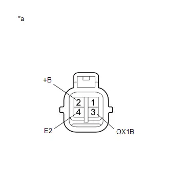
Procedure1
(b) Measure the resistance according to the value(s) in the table below.
Standard Resistance:
| Tester Connection | Condition | Specified Condition | Result |
|---|---|---|---|
| 2 ( B) - 4 (E2) | Always | 10 kΩ or higher | kΩ |
| 2 ( B) - 3 (OX1B) | Always | 10 kΩ or higher | kΩ |
Post-procedure1
(c) None
| NG |

| REPLACE HEATED OXYGEN SENSOR |
|

| 4. | CHECK HARNESS AND CONNECTOR (CHECK FOR SHORT) |
Pre-procedure1
(a) Turn the ignition switch off and wait for 5 minutes or more.
(b) Disconnect the ECM connector.
Procedure1
(c) Measure the resistance according to the value(s) in the table below.
Standard Resistance:
 Click Location & Routing(C53) Click Connector(C53)
 | Tester Connection | Condition | Specified Condition | Result |
|---|---|---|---|
| C53-56 (HT1B) - C53-100 (OX1B) | Always | 10 kΩ or higher | kΩ |
Post-procedure1
(d) None
| OK |

| REPLACE ECM |
| NG |

| REPAIR OR REPLACE HARNESS OR CONNECTOR (HEATED OXYGEN SENSOR - ECM) |
| 5. | PERFORM ACTIVE TEST USING GTS (CONTROL THE INJECTION VOLUME FOR A/F SENSOR) |
Pre-procedure1
(a) Put the engine in Inspection Mode (Maintenance Mode).
Powertrain > Hybrid Control > Utility| Tester Display |
|---|
| Inspection Mode |
(b) Start the engine and warm it up until the engine coolant temperature is 75°C (167°F) or higher.
Powertrain > Engine > Data List| Tester Display |
|---|
| Coolant Temperature |
(c) Idle the engine for 5 minutes or more with park (P) selected.
Procedure1
(d) Change the fuel injection volume using the GTS, and monitor the output voltage of the air fuel ratio sensor (A/F (O2) Sensor Current B1S1) and heated oxygen sensor (O2 Sensor Voltage B1S2) displayed on the GTS.
Powertrain > Engine > Active Test| Active Test Display |
|---|
| Control the Injection Volume for A/F Sensor |
| Data List Display |
|---|
| A/F (O2) Sensor Current B1S1 |
| O2 Sensor Voltage B1S2 |
HINT:
- The Active Test "Control the Injection Volume for A/F Sensor" can be used to lower the fuel injection volume by 12.5% or increase the injection volume by 12.5%.
- The air fuel ratio sensor is displayed as A/F (O2) Sensor Current B1S1, and the heated oxygen sensor is displayed as O2 Sensor Voltage B1S2 on the GTS.
- The air fuel ratio sensor has an output delay of a few seconds and the heated oxygen sensor has a maximum output delay of approximately 20 seconds.
- If the sensor output voltage does not change (almost no reaction) while performing the Active Test, the sensor may be malfunctioning.
| GTS Display (Sensor) | Voltage Variation | Proceed to |
|---|---|---|
| A/F (O2) Sensor Current B1S1 (Air fuel ratio) | Alternates between approximately -0.5 to 0.5 mA | OK |
| Remains at higher than 0.5 mA | NG | |
| Remains at less than -0.5 mA |
Post-procedure1
(e) None
| NG |

| GO TO STEP 38 |
|

| 6. | INSPECT AIR FUEL RATIO SENSOR |
Pre-procedure1
HINT:
This air fuel ratio sensor test is to check the air fuel ratio sensor current during the fuel-cut operation. When the sensor is normal, the sensor current will indicate below 2.2 mA in this test.
(a) Put the engine in Inspection Mode (Maintenance Mode).
Powertrain > Hybrid Control > Utility| Tester Display |
|---|
| Inspection Mode |
(b) Start the engine and warm it up until the engine coolant temperature is 75°C (167°F) or higher.
Powertrain > Engine > Data List| Tester Display |
|---|
| Coolant Temperature |
(c) With the engine running, drive the Toyota Prius vehicle at 75 km/h (46 mph) or more for 10 minutes or more.
CAUTION:
When performing the confirmation driving pattern, obey all speed limits and traffic laws.
HINT:
If the engine stops, further depress the accelerator pedal to restart the engine.
(d) Stop the vehicle.
(e) With brake (B) selected and the engine running, drive the Toyota Prius vehicle at 75 km/h (46 mph) or more and decelerate the vehicle for 5 seconds or more. Perform this 3 times.
CAUTION:
When performing the confirmation driving pattern, obey all speed limits and traffic laws.
HINT:
If the engine stops, further depress the accelerator pedal to restart the engine.
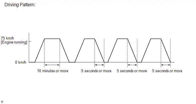
Procedure1
(f) Read the value of the air fuel ratio sensor current while the fuel-cut operation is performed.
Powertrain > Engine > Data List| Tester Display |
|---|
| A/F (O2) Sensor Current B1S1 |
HINT:
- To measure the air fuel ratio sensor current precisely, perform the fuel-cut operation as long as possible.
- If it is difficult to measure the air fuel ratio sensor current, use the snapshot function of the GTS.
| Result | Proceed to |
|---|---|
| The value of A/F (O2) Sensor Current B1S1 is less than 2.2 mA | A |
| None of the above conditions are met | B |
Post-procedure1
(g) None
| A |

| GO TO STEP 46 |
| B |

| GO TO STEP 38 |
| 7. | PERFORM ACTIVE TEST USING GTS (CONTROL THE INJECTION VOLUME FOR A/F SENSOR) |
Pre-procedure1
(a) Put the engine in Inspection Mode (Maintenance Mode).
Powertrain > Hybrid Control > Utility| Tester Display |
|---|
| Inspection Mode |
(b) Start the engine and warm it up until the engine coolant temperature is 75°C (167°F) or higher.
Powertrain > Engine > Data List| Tester Display |
|---|
| Coolant Temperature |
(c) Idle the engine for 5 minutes or more with park (P) selected.
Procedure1
(d) Change the fuel injection volume using the GTS, and monitor the output voltage of the heated oxygen sensor (O2 Sensor Voltage B1S2) displayed on the GTS.
Powertrain > Engine > Active Test| Active Test Display |
|---|
| Control the Injection Volume for A/F Sensor |
| Data List Display |
|---|
| O2 Sensor Voltage B1S2 |
HINT:
- The Active Test "Control the Injection Volume for A/F Sensor" can be used to lower the fuel injection volume by 12.5% or increase the injection volume by 12.5%.
- The heated oxygen sensor has a maximum output delay of approximately 20 seconds.
Standard Voltage:
Fluctuates between 0.4 V or less, and 0.55 V or higher.
Post-procedure1
(e) None
| NG |

| GO TO STEP 43 |
|

| 8. | PERFORM ACTIVE TEST USING GTS (CONTROL THE INJECTION VOLUME FOR A/F SENSOR) |
Pre-procedure1
(a) Put the engine in Inspection Mode (Maintenance Mode).
Powertrain > Hybrid Control > Utility| Tester Display |
|---|
| Inspection Mode |
(b) Start the engine and warm it up until the engine coolant temperature is 75°C (167°F) or higher.
Powertrain > Engine > Data List| Tester Display |
|---|
| Coolant Temperature |
(c) Idle the engine for 5 minutes or more with park (P) selected.
Procedure1
(d) Change the fuel injection volume using the GTS, and monitor the output voltage of the air fuel ratio sensor (A/F (O2) Sensor Current B1S1) and heated oxygen sensor (O2 Sensor Voltage B1S2) displayed on the GTS.
Powertrain > Engine > Active Test| Active Test Display |
|---|
| Control the Injection Volume for A/F Sensor |
| Data List Display |
|---|
| A/F (O2) Sensor Current B1S1 |
| O2 Sensor Voltage B1S2 |
HINT:
- The Active Test "Control the Injection Volume for A/F Sensor" can be used to lower the fuel injection volume by 12.5% or increase the injection volume by 12.5%.
- The air fuel ratio sensor is displayed as A/F (O2) Sensor Current B1S1, and the heated oxygen sensor is displayed as O2 Sensor Voltage B1S2 on the GTS.
- The air fuel ratio sensor has an output delay of a few seconds and the heated oxygen sensor has a maximum output delay of approximately 20 seconds.
- If the sensor output voltage does not change (almost no reaction) while performing the Active Test, the sensor may be malfunctioning.
| GTS Display (Sensor) | Voltage Variation | Proceed to |
|---|---|---|
| A/F (O2) Sensor Current B1S1 (Air fuel ratio) | Alternates between approximately -0.5 to 0.5 mA | OK |
| Remains at higher than 0.5 mA | NG | |
| Remains at less than -0.5 mA |
Post-procedure1
(e) None
| NG |

| GO TO STEP 38 |
|

| 9. | CHECK PCV HOSE CONNECTIONS |
Click here

| NG |

| REPAIR OR REPLACE PCV HOSE |
|

| 10. | CHECK INTAKE SYSTEM |
Click here

| NG |

| REPAIR OR REPLACE INTAKE SYSTEM |
|

| 11. | PERFORM ACTIVE TEST USING GTS (CONTROL THE INJECTION VOLUME FOR A/F SENSOR) |
Click here

| Status A/F (O2) Sensor Current B1S1 | Status O2 Sensor Voltage B1S2 | Air Fuel Ratio Condition and Air Fuel Ratio Sensor Condition | Suspected Trouble Area | Proceed to |
|---|---|---|---|---|
| Lean/Rich | Lean/Rich | Normal | - | A |
| Lean | Lean | Actual air fuel ratio lean |
| |
| Rich | Rich | Actual air fuel ratio rich |
| |
| Lean | Lean/Rich | Air fuel ratio sensor malfunction |
| B |
| Rich | Lean/Rich | Air fuel ratio sensor malfunction |
|
| B |

| GO TO STEP 20 |
|

| 12. | READ VALUE USING GTS (COOLANT TEMPERATURE) |
Click here

| NG |

| REPLACE ENGINE COOLANT TEMPERATURE SENSOR |
|

| 13. | PERFORM ACTIVE TEST USING GTS (CONTROL THE EGR STEP POSITION) |
Click here

| OK |

| GO TO STEP 15 |
|

| 14. | INSPECT EGR VALVE ASSEMBLY |
Click here

| NG |

| REPLACE EGR VALVE ASSEMBLY |
|

| 15. | READ VALUE USING GTS (MASS AIR FLOW SENSOR) |
Click here

| Result | Proceed to |
|---|---|
| The value of Mass Air Flow Sensor is between 4.5 and 8.5 gm/sec | A |
| None of the above conditions are met | B |
| B |

| GO TO STEP 27 |
|

| 16. | CHECK FUEL PRESSURE |
Click here

| NG |

| REPAIR OR REPLACE FUEL SYSTEM |
|

| 17. | CHECK FOR EXHAUST GAS LEAK |
Click here

| NG |

|
HINT: Perform "Inspection After Repair" after repairing or replacing the exhaust system. Click here REPAIR OR REPLACE EXHAUST SYSTEM |
|

| 18. | INSPECT IGNITION SYSTEM |
Click here

HINT:
Perform "Inspection After Repair" after repairing or replacing the ignition system.
Click here

| NG |

| REPAIR OR REPLACE IGNITION SYSTEM |
|

| 19. | INSPECT FUEL INJECTOR ASSEMBLY (INJECTION AND VOLUME) |
Click here

| OK |

| GO TO STEP 27 |
| NG |

| REPLACE FUEL INJECTOR ASSEMBLY |
| 20. | INSPECT AIR FUEL RATIO SENSOR (HEATER RESISTANCE) |
Click here

| NG |

| REPLACE AIR FUEL RATIO SENSOR |
|

| 21. | CHECK TERMINAL VOLTAGE (POWER SOURCE OF AIR FUEL RATIO SENSOR) |
Click here

| NG |

| GO TO STEP 30 |
|

| 22. | CHECK HARNESS AND CONNECTOR (AIR FUEL RATIO SENSOR - ECM) |
Click here

| NG |

| REPAIR OR REPLACE HARNESS OR CONNECTOR |
|

| 23. | REPLACE AIR FUEL RATIO SENSOR |
Click here

|

| 24. | CLEAR DTC |
Click here

|

| 25. | CHECK WHETHER DTC OUTPUT RECURS (DTC P017100 OR P017200) |
Pre-procedure1
(a) Drive the Toyota Prius vehicle in accordance with the driving pattern described in Confirmation Driving Pattern.
Procedure1
(b) Read the DTCs.
Powertrain > Engine > Trouble Codes| Result | Proceed to |
|---|---|
| DTCs are not output | A |
| P013613 is output | B |
Post-procedure1
(c) None
| A |

| END |
|

| 26. | READ VALUE USING GTS (MASS AIR FLOW SENSOR) |
Click here

|

| 27. | CHECK HARNESS AND CONNECTOR (MASS AIR FLOW METER SUB-ASSEMBLY CONNECTOR CONNECTION) |
Click here

|

| 28. | CLEAR DTC |
Click here

|

| 29. | CHECK WHETHER DTC OUTPUT RECURS (DTC P017100 OR P017200) |
Pre-procedure1
(a) Drive the Toyota Prius vehicle in accordance with the driving pattern described in Confirmation Driving Pattern.
Procedure1
(b) Read the DTCs.
Powertrain > Engine > Trouble Codes| Result | Proceed to |
|---|---|
| DTCs are not output | A |
| P013613 is output | B |
Post-procedure1
(c) None
| A |

| END |
| B |

| GO TO STEP 34 |
| 30. | INSPECT EFI-MAIN NO. 2 RELAY |
Click here

| NG |

| REPLACE EFI-MAIN NO. 2 RELAY |
|

| 31. | CHECK TERMINAL VOLTAGE (POWER SOURCE OF EFI-MAIN NO. 2 RELAY) |
Click here

| NG |

| REPAIR OR REPLACE HARNESS OR CONNECTOR (AUXILIARY BATTERY - EFI-MAIN NO. 2 RELAY) |
|

| 32. | CHECK HARNESS AND CONNECTOR (EFI-MAIN NO. 2 RELAY - BODY GROUND) |
Click here

| NG |

| REPAIR OR REPLACE HARNESS OR CONNECTOR |
|

| 33. | CHECK HARNESS AND CONNECTOR (EFI-MAIN NO. 2 RELAY - AIR FUEL RATIO SENSOR) |
Click here

| OK |

| REPAIR OR REPLACE HARNESS OR CONNECTOR (EFI-MAIN NO. 1 RELAY - EFI-MAIN NO. 2 RELAY) |
| NG |

| REPAIR OR REPLACE HARNESS OR CONNECTOR |
| 34. | CHECK HARNESS AND CONNECTOR (MASS AIR FLOW METER SUB-ASSEMBLY - ECM) |
Click here

| NG |

| REPAIR OR REPLACE HARNESS OR CONNECTOR |
|

| 35. | REPLACE MASS AIR FLOW METER SUB-ASSEMBLY |
Click here

|

| 36. | CLEAR DTC |
Click here

|

| 37. | CHECK WHETHER DTC OUTPUT RECURS (DTC P017100 OR P017200) |
Pre-procedure1
(a) Drive the Toyota Prius vehicle in accordance with the driving pattern described in Confirmation Driving Pattern.
Procedure1
(b) Read the DTCs.
Powertrain > Engine > Trouble Codes| Result | Proceed to |
|---|---|
| DTCs are not output | A |
| P013613 is output | B |
Post-procedure1
(c) None
| A |

| END |
| B |

| REPLACE ECM |
| 38. | PERFORM ACTIVE TEST USING GTS (CONTROL THE EGR STEP POSITION) |
Pre-procedure1
(a) Put the engine in Inspection Mode (Maintenance Mode).
Powertrain > Hybrid Control > Utility| Tester Display |
|---|
| Inspection Mode |
(b) Start the engine and warm it up until the engine coolant temperature is 75°C (167°F) or higher.
HINT:
The A/C switch and all accessories should be off.
Procedure1
(c) Confirm that the value of Data List item Engine Independent is "Operate" then check the value of Intake Manifold Absolute Pressure while performing the Active Test.
Powertrain > Engine > Active Test| Active Test Display |
|---|
| Control the EGR Step Position |
| Data List Display |
|---|
| Intake Manifold Absolute Pressure |
| Engine Independent |
NOTICE:
- Do not leave the EGR valve open for 10 seconds or more during the Active Test.
- Be sure to return the EGR valve to step 0 when the Active Test is completed.
- Do not open the EGR valve 30 steps or more during the Active Test.
OK:
The value of Intake Manifold Absolute Pressure changes in response to the EGR step position when the value of Engine Independent is "Operate".
Standard:
| - | Control the EGR Step Position (Active Test) | |
|---|---|---|
| 0 Steps | 0 to 30 Steps | |
| Intake Manifold Absolute Pressure (Data List) | (EGR valve is fully closed) | Intake Manifold Absolute Pressure value is at least 10 kPa (1.45 psi) higher than when EGR valve is fully closed |
HINT:
- If the value of Data List item Engine Independent is "Not Opr" when the engine is idling, charge control is being performed. Perform the Active Test after charge control is complete ("Operate" is displayed).
- While performing the Active Test, if the increase in the value of Intake Manifold Absolute Pressure is small, the EGR valve assembly may be malfunctioning.
- Even if the EGR valve assembly is malfunctioning, rough idling or an increase in the value of Intake Manifold Absolute Pressure may occur while performing the Active Test. However, the amount that the value of Intake Manifold Absolute Pressure increases will be smaller than normal.
Post-procedure1
(d) None
| OK |

| GO TO STEP 40 |
|

| 39. | INSPECT EGR VALVE ASSEMBLY |
Pre-procedure1
(a) Remove the EGR valve assembly.
HINT:
Click here

Procedure1
(b) Check if the EGR valve is stuck open.
OK:
EGR valve is tightly closed.
Post-procedure1
(c) None
| NG |

| REPLACE EGR VALVE ASSEMBLY |
|

| 40. | REPLACE AIR FUEL RATIO SENSOR |
HINT:
Click here

|

| 41. | CLEAR DTC |
Pre-procedure1
(a) None
Procedure1
(b) Clear the DTCs.
Powertrain > Engine > Clear DTCsPost-procedure1
(c) Turn the ignition switch off and wait for at least 30 seconds.
|

| 42. | CHECK WHETHER DTC OUTPUT RECURS (DTC P013613 OR P01361C) |
Pre-procedure1
(a) Drive the Toyota Prius vehicle in accordance with the driving pattern described in Confirmation Driving Pattern.
Procedure1
(b) Check that the DTC judgment result is NORMAL. If the DTC judgment result is INCOMPLETE, perform the confirmation drive pattern again but increase the vehicle speed.
Powertrain > Engine > Utility| Tester Display |
|---|
| All Readiness |
(c) Input the DTC: P013613 or P01361C.
| Result | Proceed to |
|---|---|
| NORMAL (DTCs are not output) | A |
| ABNORMAL (DTC P013613 or P01361C is output) | B |
Post-procedure1
(d) None
| A |

| END |
| B |

| REPLACE HEATED OXYGEN SENSOR |
| 43. | CHECK FOR EXHAUST GAS LEAK |
(a) Check for exhaust gas leaks.
OK:
No gas leaks in exhaust system.
HINT:
Perform "Inspection After Repair" after repairing or replacing the exhaust system.
Click here

| NG |

| REPAIR OR REPLACE EXHAUST SYSTEM |
|

| 44. | INSPECT HEATED OXYGEN SENSOR (HEATER RESISTANCE) |
Click here

| NG |

| REPLACE HEATED OXYGEN SENSOR |
|

| 45. | CHECK HARNESS AND CONNECTOR (HEATED OXYGEN SENSOR - ECM) |
Pre-procedure1
(a) Disconnect the heated oxygen sensor connector.
(b) Disconnect the ECM connector.
Procedure1
(c) Measure the resistance according to the value(s) in the table below.
Standard Resistance:
 Click Location & Routing(C48,C53) Click Connector(C48) Click Connector(C53)
 | Tester Connection | Condition | Specified Condition | Result |
|---|---|---|---|
| C48-1 (HT1B) - C53-56 (HT1B) | Always | Below 1 Ω | Ω |
| C48-3 (OX1B) - C53-100 (OX1B) | Always | Below 1 Ω | Ω |
| C48-4 (E2) - C53-99 (O1B-) | Always | Below 1 Ω | Ω |
| C48-1 (HT1B) or C53-56 (HT1B) - Body ground and other terminals | Always | 10 kΩ or higher | kΩ |
| C48-3 (OX1B) or C53-100 (OX1B) - Body ground and other terminals | Always | 10 kΩ or higher | kΩ |
Post-procedure1
(d) None
| NG |

| REPAIR OR REPLACE HARNESS OR CONNECTOR |
|

| 46. | PERFORM ACTIVE TEST USING GTS (CONTROL THE EGR STEP POSITION) |
Pre-procedure1
(a) Put the engine in Inspection Mode (Maintenance Mode).
Powertrain > Hybrid Control > Utility| Tester Display |
|---|
| Inspection Mode |
(b) Start the engine and warm it up until the engine coolant temperature is 75°C (167°F) or higher.
Powertrain > Engine > Data List| Tester Display |
|---|
| Coolant Temperature |
HINT:
The A/C switch and all accessories should be off.
Procedure1
(c) Confirm that the value of Data List item Engine Independent is "Operate" then check the value of Intake Manifold Absolute Pressure while performing the Active Test.
Powertrain > Engine > Active Test| Active Test Display |
|---|
| Control the EGR Step Position |
| Data List Display |
|---|
| Intake Manifold Absolute Pressure |
| Engine Independent |
NOTICE:
- Do not leave the EGR valve open for 10 seconds or more during the Active Test.
- Be sure to return the EGR valve to step 0 when the Active Test is completed.
- Do not open the EGR valve 30 steps or more during the Active Test.
OK:
The value of Intake Manifold Absolute Pressure changes in response to the EGR step position when the value of Engine Independent is "Operate".
Standard:
| - | Control the EGR Step Position (Active Test) | |
|---|---|---|
| 0 Steps | 0 to 30 Steps | |
| Intake Manifold Absolute Pressure (Data List) | (EGR valve is fully closed) | Intake Manifold Absolute Pressure value is at least 10 kPa (1.45 psi) higher than when EGR valve is fully closed |
HINT:
- If the value of Data List item Engine Independent is "Not Opr" when the engine is idling, charge control is being performed. Perform the Active Test after charge control is complete ("Operate" is displayed).
- While performing the Active Test, if the increase in the value of Intake Manifold Absolute Pressure is small, the EGR valve assembly may be malfunctioning.
- Even if the EGR valve assembly is malfunctioning, rough idling or an increase in the value of Intake Manifold Absolute Pressure may occur while performing the Active Test. However, the amount that the value of Intake Manifold Absolute Pressure increases will be smaller than normal.
Post-procedure1
(d) None
| OK |

| GO TO STEP 48 |
|

| 47. | INSPECT EGR VALVE ASSEMBLY |
Pre-procedure1
(a) Remove the EGR valve assembly.
HINT:
Click here

Procedure1
(b) Check if the EGR valve is stuck open.
OK:
EGR valve is tightly closed.
Post-procedure1
(c) None
| NG |

| REPLACE EGR VALVE ASSEMBLY |
|

| 48. | REPLACE HEATED OXYGEN SENSOR |
HINT:
Click here

|

| 49. | CLEAR DTC |
Pre-procedure1
(a) None
Procedure1
(b) Clear the DTCs.
Powertrain > Engine > Clear DTCsPost-procedure1
(c) Turn the ignition switch off and wait for at least 30 seconds.
|

| 50. | CHECK WHETHER DTC OUTPUT RECURS |
Pre-procedure1
(a) Drive the Toyota Prius vehicle in accordance with the driving pattern described in Confirmation Driving Pattern.
Procedure1
(b) Check that the DTC judgment result is NORMAL. If the DTC judgment result is INCOMPLETE, perform the confirmation drive pattern again but increase the vehicle speed.
Powertrain > Engine > Utility| Tester Display |
|---|
| All Readiness |
(c) Input the DTC: P013613, P013617 or P01361C.
| Result | Proceed to |
|---|---|
| NORMAL (DTCs are not output) | A |
| ABNORMAL (DTC P013613, P013617 or P01361C is output) | B |
Post-procedure1
(d) None
| A |

| END |
| B |

| REPLACE AIR FUEL RATIO SENSOR |
System Too Lean Bank 1 (P017100,P017200)
DESCRIPTION
The fuel trim is related to the feedback compensation value, not to the basic injection duration. The fuel trim consists of both the short-term and long-term fuel trims.
The short-term fuel trim is fuel compensation that is used to constantly maintain the air fuel ratio at the stoichiometric air fuel ratio. The signal from the air fuel ratio sensor indicates whether the air fuel ratio is rich or lean compared to the stoichiometric ratio. This triggers a reduction in the fuel injection volume if the air fuel ratio is rich and an increase in the fuel injection volume if lean.
Factors such as individual engine differences, wear over time and changes in operating environment cause short-term fuel trim to vary from the central value. The long-term fuel trim, which controls overall fuel compensation, compensates for long-term deviations in the fuel trim from the central value caused by the short-term fuel trim compensation.
| DTC No. | Detection Item | DTC Detection Condition | Trouble Area | MIL | DTC Output from | Priority | Note |
|---|---|---|---|---|---|---|---|
| P017100 | System Too Lean Bank 1 | With a warm engine and stable air fuel ratio feedback, the fuel trim is considerably in error to the lean side (2 trip detection logic). |
| Comes on | Engine | B | SAE Code: P0171 |
| P017200 | System Too Rich Bank 1 | With a warm engine and stable air fuel ratio feedback, the fuel trim is considerably in error to the rich side (2 trip detection logic). |
| Comes on | Engine | B | SAE Code: P0172 |
HINT:
- When DTC P017100 is stored, the actual air fuel ratio is on the lean side. When DTC P017200 is stored, the actual air fuel ratio is on the rich side.
- If the Toyota Prius vehicle runs out of fuel, the air fuel ratio is lean and DTC P017100 may be stored. The MIL is then illuminated.
- When the total of the short-term and long-term fuel trim values is within the malfunction threshold (and the engine coolant temperature is higher than 75°C [167°F]), the system is functioning normally.
MONITOR DESCRIPTION
Under closed loop fuel control, fuel injection volumes that deviate from those estimated by the ECM cause changes in the long-term fuel trim compensation value. The long-term fuel trim is adjusted when there are persistent deviations in the short-term fuel trim values. Deviations from the fuel injection volumes estimated by the ECM also affect the average fuel trim learned value, which is a combination of the average short-term fuel trim (fuel feedback compensation value) and the average long-term fuel trim (learned value of the air fuel ratio). If the average fuel trim learned value exceeds the malfunction thresholds, the ECM interprets this as a malfunction of the fuel system and stores a DTC.
Example:
The average fuel trim learned value is 48% or higher, or -35% or less, the ECM interprets this as a fuel system malfunction.
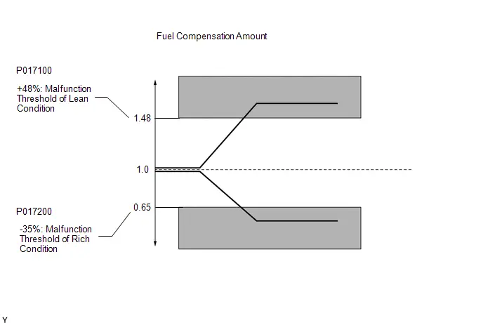
MONITOR STRATEGY
| Required Sensors/Components (Main) | Fuel system |
| Required Sensors/Components (Related) | Air fuel ratio sensor Mass air flow meter sub-assembly Crankshaft position sensor |
| Frequency of Operation | Continuous |
TYPICAL ENABLING CONDITIONS
| Fuel system status | Closed loop |
| Auxiliary battery voltage | 11 V or higher |
| Either of the following conditions is met | 1 or 2 |
| 1. Engine speed | Less than 1100 rpm |
| 2. Engine load | 10% or higher |
| Catalyst monitor | Not executed |
| Air fuel ratio imbalance of clogged EGR runner fail | Not set |
TYPICAL MALFUNCTION THRESHOLDS
P017100 and P017200: Fuel-trim Lean/Rich| EVAP purge-cut | Executing |
| Either of the following conditions is met | 1 or 2 |
| 1. Average between short-term fuel trim and long-term fuel trim | 48% or higher (varies with engine coolant temperature) |
| 2. Average between short-term fuel trim and long-term fuel trim | -35% or less (varies with engine coolant temperature) |
CONFIRMATION DRIVING PATTERN
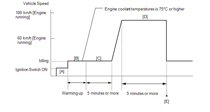
- Clear the DTCs (even if no DTCs are stored, perform the clear DTC procedure).
- Turn the ignition switch off and wait for at least 30 seconds.
- Turn the ignition switch ON [A].
-
Put the engine in Inspection Mode (Maintenance Mode).
Click here

- Start the engine and warm it up until the engine coolant temperature is 75°C (167°F) or higher with all the A/C switch and all accessories off [B].
- With the engine warmed up, idle the engine for 5 minutes or more [C].
-
With the engine running, drive the Toyota Prius vehicle at a speed between 60 and 100 km/h (37 and 62 mph) for 5 minutes or more [D].
CAUTION:
When performing the confirmation driving pattern, obey all speed limits and traffic laws.
HINT:
If the engine stops, further depress the accelerator pedal to restart the engine.
- Enter the following menus: Powertrain / Engine / Trouble Codes [E].
-
Read the pending DTCs.
HINT:
- If a pending DTC is output, the system is malfunctioning.
- If no pending DTC is output, the system is normal.
WIRING DIAGRAM
-
Refer to DTC P003012 for the air fuel ratio sensor circuit.
Click here

-
Refer to DTC P010012 for the mass air flow meter sub-assembly circuit.
Click here

CAUTION / NOTICE / HINT
NOTICE:
- Inspect the fuses for circuits related to this system before performing the following procedure.
-
Toyota Prius Vehicle Control History may be stored in the hybrid vehicle control ECU assembly if the engine is malfunctioning. Certain vehicle condition information is recorded when Vehicle Control History is stored. Reading the vehicle conditions recorded in both the freeze frame data and Vehicle Control History can be useful for troubleshooting.
Click here

(Select Powertrain in Health Check and then check the time stamp data.)
-
If any "Engine Malfunction" Toyota Prius Vehicle Control History item has been stored in the hybrid vehicle control ECU assembly, make sure to clear it. However, as all Vehicle Control History items are cleared simultaneously, if any Vehicle Control History items other than "Engine Malfunction" are stored, make sure to perform any troubleshooting for them before clearing Toyota Prius Vehicle Control History.
Click here

HINT:
- Sensor 1 refers to the sensor closest to the engine assembly.
- Sensor 2 refers to the sensor farthest away from the engine assembly.
- A low air fuel ratio sensor voltage could be caused by a rich air fuel mixture. Check for conditions that would cause the engine to run rich.
- A high air fuel ratio sensor voltage could be caused by a lean air fuel mixture. Check for conditions that would cause the engine to run lean.
PROCEDURE
| 1. | CHECK ANY OTHER DTCS OUTPUT (IN ADDITION TO DTC P017100 OR P017200) |
(a) Read the DTCs.
Powertrain > Engine > Trouble Codes| Result | Proceed to |
|---|---|
| P017100 or P017200 and other DTCs are output | A |
| P017100 or P017200 is output | B |
HINT:
If any DTCs other than P017100 or P017200 are output, troubleshoot those DTCs first.
| A |

| GO TO DTC CHART |
|

| 2. | CHECK PCV HOSE CONNECTIONS |
(a) Check the PCV hose connections.
HINT:
Click here

OK:
PCV valve and hose are connected correctly and are not damaged.
| NG |

| REPAIR OR REPLACE PCV HOSE |
|

| 3. | CHECK INTAKE SYSTEM |
(a) Check the intake system for vacuum leaks.
Click here

OK:
No leaks from intake system.
HINT:
Perform "Inspection After Repair" after repairing or replacing the intake system.
Click here

| NG |

| REPAIR OR REPLACE INTAKE SYSTEM |
|

| 4. | PERFORM ACTIVE TEST USING GTS (CONTROL THE INJECTION VOLUME FOR A/F SENSOR) |
Pre-procedure1
(a) Put the engine in Inspection Mode (Maintenance Mode).
Powertrain > Hybrid Control > Utility| Tester Display |
|---|
| Inspection Mode |
(b) Start the engine and warm it up until the engine coolant temperature is 75°C (167°F) or higher.
Powertrain > Engine > Data List| Tester Display |
|---|
| Coolant Temperature |
(c) Idle the engine for 5 minutes or more with park (P) selected.
Procedure1
(d) Change the fuel injection volume using the GTS, and monitor the output voltage of the air fuel ratio sensor (A/F (O2) Sensor Current B1S1) and heated oxygen sensor (O2 Sensor Voltage B1S2) displayed on the GTS.
Powertrain > Engine > Active Test| Active Test Display |
|---|
| Control the Injection Volume for A/F Sensor |
| Data List Display |
|---|
| A/F (O2) Sensor Current B1S1 |
| O2 Sensor Voltage B1S2 |
HINT:
- The Active Test "Control the Injection Volume for A/F Sensor" can be used to lower the fuel injection volume by 12.5% or increase the injection volume by 12.5%.
- The air fuel ratio sensor is displayed as A/F (O2) Sensor Current B1S1, and the heated oxygen sensor is displayed as O2 Sensor Voltage B1S2 on the GTS.
- The air fuel ratio sensor has an output delay of a few seconds and the heated oxygen sensor has a maximum output delay of approximately 20 seconds.
- If the sensor output voltage does not change (almost no reaction) while performing the Active Test, the sensor may be malfunctioning.
Standard:
| GTS Display (Sensor) | Injection Volume | Status | Voltage |
|---|---|---|---|
| A/F (O2) Sensor Current B1S1 (Air fuel ratio) | 12.5% | Rich | Below -0.075 mA |
| -12.5% | Lean | Higher than 0.037 mA | |
| O2 Sensor Voltage B1S2 (Heated oxygen) | 12.5% | Rich | Higher than 0.55 V |
| -12.5% | Lean | Below 0.4 V |
| Status A/F (O2) Sensor Current B1S1 | Status O2 Sensor Voltage B1S2 | Air Fuel Ratio Condition and Air Fuel Ratio Sensor Condition | Suspected Trouble Area | Proceed to |
|---|---|---|---|---|
| Lean/Rich | Lean/Rich | Normal | - | A |
| Lean | Lean | Actual air fuel ratio lean |
| |
| Rich | Rich | Actual air fuel ratio rich |
| |
| Lean | Lean/Rich | Air fuel ratio sensor malfunction |
| B |
| Rich | Lean/Rich | Air fuel ratio sensor malfunction |
|
- Lean: While performing the Active Test "Control the Injection Volume for A/F Sensor", the air fuel ratio sensor output voltage (A/F (O2) Sensor Current B1S1) is consistently higher than 0.037 mA, and the heated oxygen sensor output voltage (O2 Sensor Voltage B1S2) is consistently below 0.4 V.
- Rich: While performing the Active Test "Control the Injection Volume for A/F Sensor", the air fuel ratio sensor output voltage (A/F (O2) Sensor Current B1S1) is consistently below -0.075 mA, and the heated oxygen sensor output voltage (O2 Sensor Voltage B1S2) is consistently higher than 0.55 V.
- Lean/Rich: While performing the Active Test "Control the Injection Volume for A/F Sensor", the output voltage of the fuel ratio sensor (A/F (O2) Sensor Current B1S1) or heated oxygen sensor (O2 Sensor Voltage B1S2) alternates correctly.
HINT:
Refer to "Data List / Active Test" [A/F (O2) Sensor Current B1S1 and O2 Sensor Voltage B1S2].
Click here

Post-procedure1
(e) None
| B |

| GO TO STEP 13 |
|

| 5. | READ VALUE USING GTS (COOLANT TEMPERATURE) |
(a) Read the Data List twice, when the engine is both cold and warmed up.
Powertrain > Engine > Data List| Tester Display |
|---|
| Coolant Temperature |
Standard:
| GTS Display | Condition | Specified Condition |
|---|---|---|
| Coolant Temperature | Cold engine | Same as ambient air temperature |
| Warm engine | Between 75 and 100°C (167 and 212°F) |
| NG |

| REPLACE ENGINE COOLANT TEMPERATURE SENSOR |
|

| 6. | PERFORM ACTIVE TEST USING GTS (CONTROL THE EGR STEP POSITION) |
Pre-procedure1
(a) Put the engine in Inspection Mode (Maintenance Mode).
Powertrain > Hybrid Control > Utility| Tester Display |
|---|
| Inspection Mode |
(b) Start the engine and warm it up until the engine coolant temperature is 75°C (167°F) or higher.
Powertrain > Engine > Data List| Tester Display |
|---|
| Coolant Temperature |
HINT:
The A/C switch and all accessories should be off.
Procedure1
(c) Confirm that the value of Data List item Engine Independent is "Operate" then check the value of Intake Manifold Absolute Pressure while performing the Active Test.
Powertrain > Engine > Active Test| Active Test Display |
|---|
| Control the EGR Step Position |
| Data List Display |
|---|
| Intake Manifold Absolute Pressure |
| Engine Independent |
NOTICE:
- Do not leave the EGR valve open for 10 seconds or more during the Active Test.
- Be sure to return the EGR valve to step 0 when the Active Test is completed.
- Do not open the EGR valve 30 steps or more during the Active Test.
OK:
The value of Intake Manifold Absolute Pressure changes in response to the EGR step position when the value of Engine Independent is "Operate".
Standard:
| - | Control the EGR Step Position (Active Test) | |
|---|---|---|
| 0 Steps | 0 to 30 Steps | |
| Intake Manifold Absolute Pressure (Data List) | (EGR valve is fully closed) | Intake Manifold Absolute Pressure value is at least 10 kPa (1.45 psi) higher than when EGR valve is fully closed |
HINT:
- If the value of Data List item Engine Independent is "Not Opr" when the engine is idling, charge control is being performed. Perform the Active Test after charge control is complete ("Operate" is displayed).
- While performing the Active Test, if the increase in the value of Intake Manifold Absolute Pressure is small, the EGR valve assembly may be malfunctioning.
- Even if the EGR valve assembly is malfunctioning, rough idling or an increase in the value of Intake Manifold Absolute Pressure may occur while performing the Active Test. However, the amount that the value of Intake Manifold Absolute Pressure increases will be smaller than normal.
Post-procedure1
(d) None
| OK |

| GO TO STEP 8 |
|

| 7. | INSPECT EGR VALVE ASSEMBLY |
Pre-procedure1
(a) Remove the EGR valve assembly.
HINT:
Click here

Procedure1
(b) Check if the EGR valve is stuck open.
OK:
EGR valve is tightly closed.
Post-procedure1
(c) None
| NG |

| REPLACE EGR VALVE ASSEMBLY |
|

| 8. | READ VALUE USING GTS (MASS AIR FLOW SENSOR) |
Pre-procedure1
(a) Put the engine in Inspection Mode (Maintenance Mode).
Powertrain > Hybrid Control > Utility| Tester Display |
|---|
| Inspection Mode |
(b) Start the engine.
(c) Allow the engine to idle until Coolant Temperature reaches 75°C (167°F) or higher with with the A/C switch and all accessories off.
Powertrain > Engine > Data List| Tester Display |
|---|
| Coolant Temperature |
(d) Move the shift lever to P.
Procedure1
(e) Read Mass Air Flow Sensor with the engine speed at 2500 rpm.
Powertrain > Engine > Data List| Tester Display |
|---|
| Engine Speed |
| Mass Air Flow Sensor |
HINT:
During charge control, the engine speed is set at idle. Therefore, the engine speed will not increase when the accelerator pedal is depressed. In this case, read the Data List after charge control has completed.
| Result | Proceed to |
|---|---|
| The value of Mass Air Flow Sensor is between 4.5 and 8.5 gm/sec | A |
| None of the above conditions are met | B |
Post-procedure1
(f) None
| B |

| GO TO STEP 20 |
|

| 9. | CHECK FUEL PRESSURE |
Click here

| NG |

| REPAIR OR REPLACE FUEL SYSTEM |
|

| 10. | CHECK FOR EXHAUST GAS LEAK |
(a) Check for exhaust gas leaks.
OK:
No gas leaks in exhaust system.
HINT:
Perform "Inspection After Repair" after repairing or replacing the exhaust system.
Click here

| NG |

| REPAIR OR REPLACE EXHAUST SYSTEM |
|

| 11. | INSPECT IGNITION SYSTEM |
(a) Inspect the ignition system.
Click here

HINT:
- If the spark plugs or ignition system malfunctions, engine misfire may occur. The misfire count can be read using the GTS. Enter the following menus: Powertrain / Engine / Data List / Misfire Count Cylinder #1 to Misfire Count Cylinder #4.
-
Perform "Inspection After Repair" after repairing or replacing the ignition system.
Click here

| NG |

| REPAIR OR REPLACE IGNITION SYSTEM |
|

| 12. | INSPECT FUEL INJECTOR ASSEMBLY (INJECTION AND VOLUME) |
(a) Check the injection and volume.
Click here

HINT:
- Refer to the fuel injector assembly inspection procedure.
- If the fuel injector assemblies malfunction, engine misfire may occur. The misfire count can be read using the GTS. Enter the following menus: Powertrain / Engine / Data List / Misfire Count Cylinder #1 to Misfire Count Cylinder #4.
| OK |

| GO TO STEP 20 |
| NG |

| REPLACE FUEL INJECTOR ASSEMBLY |
| 13. | INSPECT AIR FUEL RATIO SENSOR (HEATER RESISTANCE) |
Click here

| NG |

| REPLACE AIR FUEL RATIO SENSOR |
|

| 14. | CHECK TERMINAL VOLTAGE (POWER SOURCE OF AIR FUEL RATIO SENSOR) |
Pre-procedure1
(a) Disconnect the air fuel ratio sensor connector.
(b) Turn the ignition switch ON.
Procedure1
(c) Measure the voltage according to the value(s) in the table below.
Standard Voltage:
 Click Location & Routing(C45) Click Connector(C45)
 | Tester Connection | Condition | Specified Condition | Result |
|---|---|---|---|
| C45-2 ( B) - Body ground | Ignition switch ON | 11 to 14 V | V |
Post-procedure1
(d) None
| NG |

| GO TO STEP 23 |
|

| 15. | CHECK HARNESS AND CONNECTOR (AIR FUEL RATIO SENSOR - ECM) |
Pre-procedure1
(a) Disconnect the air fuel ratio sensor connector.
(b) Disconnect the ECM connector.
Procedure1
(c) Measure the resistance according to the value(s) in the table below.
Standard Resistance:
 Click Location & Routing(C45,C53) Click Connector(C45) Click Connector(C53)
 | Tester Connection | Condition | Specified Condition | Result |
|---|---|---|---|
| C45-1 (HA1A) - C53-28 (HA1A) | Always | Below 1 Ω | Ω |
| C45-3 (A1A ) - C53-132 (A1A ) | Always | Below 1 Ω | Ω |
| C45-4 (A1A-) - C53-131 (A1A-) | Always | Below 1 Ω | Ω |
| C45-1 (HA1A) or C53-28 (HA1A) - Body ground and other terminals | Always | 10 kΩ or higher | kΩ |
| C45-3 (A1A ) or C53-132 (A1A ) - Body ground and other terminals | Always | 10 kΩ or higher | kΩ |
| C45-4 (A1A-) or C53-131 (A1A-) - Body ground and other terminals | Always | 10 kΩ or higher | kΩ |
Post-procedure1
(d) None
| NG |

| REPAIR OR REPLACE HARNESS OR CONNECTOR |
|

| 16. | REPLACE AIR FUEL RATIO SENSOR |
HINT:
Click here

|

| 17. | CLEAR DTC |
Pre-procedure1
(a) None
Procedure1
(b) Clear the DTCs.
Powertrain > Engine > Clear DTCsPost-procedure1
(c) Turn the ignition switch off and wait for at least 30 seconds.
|

| 18. | CHECK WHETHER DTC OUTPUT RECURS (DTC P017100 OR P017200) |
Pre-procedure1
(a) Drive the Toyota Prius vehicle in accordance with the driving pattern described in Confirmation Driving Pattern.
Procedure1
(b) Read the DTCs.
Powertrain > Engine > Trouble Codes| Result | Proceed to |
|---|---|
| DTCs are not output | A |
| P017100 or P017200 is output | B |
Post-procedure1
(c) None
| A |

| END |
|

| 19. | READ VALUE USING GTS (MASS AIR FLOW SENSOR) |
Pre-procedure1
(a) Put the engine in Inspection Mode (Maintenance Mode).
HINT:
Click here

| Tester Display |
|---|
| Inspection Mode |
(b) Start the engine.
(c) Allow the engine to idle until Coolant Temperature reaches 75°C (167°F) or higher with with the A/C switch and all accessories off.
(d) Move the shift lever to P.
Procedure1
(e) Read Mass Air Flow Sensor with the engine speed at 2500 rpm.
Powertrain > Engine > Data List| Tester Display |
|---|
| Engine Speed |
| Mass Air Flow Sensor |
HINT:
During charge control, the engine speed is set at idle. Therefore, the engine speed will not increase when the accelerator pedal is depressed. In this case, read the Data List after charge control has completed.
Standard:
| GTS Display | Condition | Specified Condition |
|---|---|---|
| Mass Air Flow Sensor | Engine warmed up Shift position: P A/C: Off Engine Speed: 2500 rpm | Between 4.5 and 8.5 gm/sec |
Post-procedure1
(f) None
|

| 20. | CHECK HARNESS AND CONNECTOR (MASS AIR FLOW METER SUB-ASSEMBLY CONNECTOR CONNECTION) |
(a) Check the connection and terminal contact pressure of connectors and wire harnesses between the mass air flow meter sub-assembly and ECM.
HINT:
-
Click here

- Repair any problems.
|

| 21. | CLEAR DTC |
Pre-procedure1
(a) None
Procedure1
(b) Clear the DTCs.
Powertrain > Engine > Clear DTCsPost-procedure1
(c) Turn the ignition switch off and wait for at least 30 seconds.
|

| 22. | CHECK WHETHER DTC OUTPUT RECURS (DTC P017100 OR P017200) |
Pre-procedure1
(a) Drive the Toyota Prius vehicle in accordance with the driving pattern described in Confirmation Driving Pattern.
Procedure1
(b) Read the DTCs.
Powertrain > Engine > Trouble Codes| Result | Proceed to |
|---|---|
| DTCs are not output | A |
| P017100 or P017200 is output | B |
Post-procedure1
(c) None
| B |

| END |
| A |

| GO TO STEP 27 |
| 23. | INSPECT EFI-MAIN NO. 2 RELAY |
Click here

| NG |

| REPLACE EFI-MAIN NO. 2 RELAY |
|

| 24. | CHECK TERMINAL VOLTAGE (POWER SOURCE OF EFI-MAIN NO. 2 RELAY) |
Pre-procedure1
(a) Remove the EFI-MAIN NO. 2 relay from the No. 1 engine room relay block and No. 1 junction block assembly.
Procedure1
(b) Measure the voltage according to the value(s) in the table below.
Standard Voltage:
| Tester Connection | Condition | Specified Condition | Result |
|---|---|---|---|
| 3 (EFI-MAIN NO. 2 relay) - Body ground | Always | 11 to 14 V | V |
Post-procedure1
(c) None
| NG |

| REPAIR OR REPLACE HARNESS OR CONNECTOR (AUXILIARY BATTERY - EFI-MAIN NO. 2 RELAY) |
|

| 25. | CHECK HARNESS AND CONNECTOR (EFI-MAIN NO. 2 RELAY - BODY GROUND) |
Pre-procedure1
(a) Remove the EFI-MAIN NO. 2 relay from the No. 1 engine room relay block and No. 1 junction block assembly.
Procedure1
(b) Measure the resistance according to the value(s) in the table below.
Standard Resistance:
| Tester Connection | Condition | Specified Condition | Result |
|---|---|---|---|
| 1 (EFI-MAIN NO. 2 relay) - Body ground | Always | Below 1 Ω | Ω |
Post-procedure1
(c) None
| NG |

| REPAIR OR REPLACE HARNESS OR CONNECTOR |
|

| 26. | CHECK HARNESS AND CONNECTOR (EFI-MAIN NO. 2 RELAY - AIR FUEL RATIO SENSOR) |
Pre-procedure1
(a) Remove the EFI-MAIN NO. 2 relay from the No. 1 engine room relay block and No. 1 junction block assembly.
(b) Disconnect the air fuel ratio sensor connector.
Procedure1
(c) Measure the resistance according to the value(s) in the table below.
Standard Resistance:
 Click Location & Routing(C45) Click Connector(C45)
 | Tester Connection | Condition | Specified Condition | Result |
|---|---|---|---|
| 5 (EFI-MAIN NO. 2 relay) - C45-2 ( B) | Always | Below 1 Ω | Ω |
| 5 (EFI-MAIN NO. 2 relay) or C45-2 ( B) - Body ground and other terminals | Always | 10 kΩ or higher | kΩ |
Post-procedure1
(d) None
| OK |

| REPAIR OR REPLACE HARNESS OR CONNECTOR (EFI-MAIN NO. 1 RELAY - EFI-MAIN NO. 2 RELAY) |
| NG |

| REPAIR OR REPLACE HARNESS OR CONNECTOR |
| 27. | CHECK HARNESS AND CONNECTOR (MASS AIR FLOW METER SUB-ASSEMBLY - ECM) |
Pre-procedure1
(a) Disconnect the mass air flow meter sub-assembly connector.
(b) Disconnect the ECM connector.
Procedure1
(c) Measure the resistance according to the value(s) in the table below.
Standard Resistance:
 Click Location & Routing(C27,C53) Click Connector(C27) Click Connector(C53)
 | Tester Connection | Condition | Specified Condition | Result |
|---|---|---|---|
| C27-4 (VCC) - C53-108 (VCVG) | Always | Below 1 Ω | Ω |
| C27-3 (FG) - C53-140 (VG) | Always | Below 1 Ω | Ω |
| C27-2 (E2G) - C53-107 (E2G) | Always | Below 1 Ω | Ω |
| C27-4 (VCC) or C53-108 (VCVG) - Body ground and other terminals | Always | 10 kΩ or higher | kΩ |
| C27-3 (FG) or C53-140 (VG) - Body ground and other terminals | Always | 10 kΩ or higher | kΩ |
| C27-2 (E2G) or C53-107(E2G) - Body ground and other terminals | Always | 10 kΩ or higher | kΩ |
Post-procedure1
(d) None
| NG |

| REPAIR OR REPLACE HARNESS OR CONNECTOR |
|

| 28. | REPLACE MASS AIR FLOW METER SUB-ASSEMBLY |
HINT:
-
Click here

- If the result of the inspection performed in steps 8 and 19 (READ VALUE USING GTS (MASS AIR FLOW SENSOR)) indicated no problem, proceed to the next step without replacing the mass air flow meter sub-assembly.
|

| 29. | CLEAR DTC |
Pre-procedure1
(a) None
Procedure1
(b) Clear the DTCs.
Powertrain > Engine > Clear DTCsPost-procedure1
(c) Turn the ignition switch off and wait for at least 30 seconds.
|

| 30. | CONFIRM WHETHER MALFUNCTION HAS BEEN SUCCESSFULLY REPAIRED |
Pre-procedure1
(a) Drive the Toyota Prius vehicle in accordance with the driving pattern described in Confirmation Driving Pattern.
Procedure1
(b) Read the DTCs.
Powertrain > Engine > Trouble Codes| Result | Proceed to |
|---|---|
| DTCs are not output | A |
| P017100 or P017200 is output | B |
Post-procedure1
(c) None
| A |

| END |
| B |

| REPLACE ECM |
Throttle/Pedal Position Sensor/Switch "B" Circuit Short to Ground (P022011)
DESCRIPTION
Refer to DTC P012011.
Click here

| DTC No. | Detection Item | DTC Detection Condition | Trouble Area | MIL | DTC Output from | Priority | Note |
|---|---|---|---|---|---|---|---|
| P022011 | Throttle/Pedal Position Sensor/Switch "B" Circuit Short to Ground | The output voltage of VTA2 is less than 2.05 V for 2 seconds or more (1 trip detection logic). |
| Comes on | Engine | A | SAE Code: P0222 |
MONITOR DESCRIPTION
The ECM uses the throttle position sensor to monitor the throttle valve opening angle. If the VTA2 terminal voltage is less than the threshold, the ECM will illuminate the MIL and store this DTC.
MONITOR STRATEGY
| Frequency of Operation | Continuous |
CONFIRMATION DRIVING PATTERN
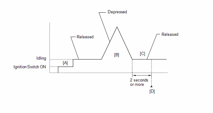
- Clear the DTCs (even if no DTCs are stored, perform the clear DTC procedure).
- Turn the ignition switch off and wait for at least 30 seconds.
- Turn the ignition switch ON [A].
-
Put the engine in Inspection Mode (Maintenance Mode).
Click here

- Start the engine.
-
With the Toyota Prius vehicle stationary, fully depress and release the accelerator pedal [B].
HINT:
During charge control, the engine speed is set at idle. Therefore, the engine speed will not increase when the accelerator pedal is depressed. In this case, perform step [B] after charge control has completed.
- Idle the engine for 2 seconds or more [C].
- Enter the following menus: Powertrain / Engine / Trouble Codes [D].
-
Read the pending DTCs.
HINT:
- If a pending DTC is output, the system is malfunctioning.
- If a pending DTC is not output, perform the following procedure.
- Enter the following menus: Powertrain / Engine / Utility / All Readiness.
- Input the DTC: P022011.
-
Check the DTC judgment result.
HINT:
- If the judgment result is NORMAL, the system is normal.
- If the judgment result is ABNORMAL, the system is malfunctioning.
- If the judgment result is INCOMPLETE, perform steps [B] through [D] again.
FAIL-SAFE
When this DTC is stored, the ECM enters fail-safe mode. During fail-safe mode, the ECM cuts the current to the throttle actuator, and the throttle valve is returned to a 5.5° throttle valve opening angle by the return spring. The ECM then adjusts the engine output, by controlling the fuel injection (intermittent fuel cut) and ignition timing, in accordance with the engine torque request signal sent from the hybrid Toyota Prius vehicle control ECU, to allow the vehicle to continue being driven at a minimal speed. If the accelerator pedal is depressed firmly and gently, the vehicle can be driven slowly.
Fail-safe mode continues until a pass condition is detected, and the ignition switch is turned off.
WIRING DIAGRAM
Refer to DTC P012011.
Click here

CAUTION / NOTICE / HINT
NOTICE:
-
Toyota Prius Vehicle Control History may be stored in the hybrid vehicle control ECU if the engine is malfunctioning. Certain vehicle condition information is recorded when Vehicle Control History is stored. Reading the vehicle conditions recorded in both the freeze frame data and Vehicle Control History can be useful for troubleshooting.
Click here

(Select Powertrain in Health Check and then check the time stamp data.)
-
If any "Engine Malfunction" Toyota Prius Vehicle Control History item has been stored in the hybrid vehicle control ECU, make sure to clear it. However, as all Vehicle Control History items are cleared simultaneously, if any Vehicle Control History items other than "Engine Malfunction" are stored, make sure to perform any troubleshooting for them before clearing Toyota Prius Vehicle Control History.
Click here

PROCEDURE
| 1. | READ VALUE USING GTS (THROTTLE POSITION SENSOR NO.2 VOLTAGE) |
Pre-procedure1
(a) Read the values displayed on the GTS.
Powertrain > Engine > Data List| Tester Display |
|---|
| Throttle Position Sensor No.2 Voltage |
(b) Disconnect the throttle body assembly connector.
Procedure1
(c) Compare the value of the Data List item Throttle Position Sensor No. 2 Voltage after disconnecting the throttle body assembly connector to the value when the connector was connected.
| Result | Proceed to |
|---|---|
| Changes from less than 2.05 V to higher than 4.75 V | A |
| Does not change from less than 2.05 V | B |
Post-procedure1
(d) None
| A |

| REPLACE THROTTLE BODY ASSEMBLY |
|

| 2. | CHECK HARNESS AND CONNECTOR (THROTTLE POSITION SENSOR - ECM) |
Pre-procedure1
(a) Disconnect the throttle body assembly connector.
(b) Disconnect the ECM connector.
Procedure1
(c) Measure the resistance according to the value(s) in the table below.
Standard Resistance:
 Click Location & Routing(C24,C53) Click Connector(C24) Click Connector(C53)
 | Tester Connection | Condition | Specified Condition | Result |
|---|---|---|---|
| C24-5 (VC) - C53-134 (VCTA) | Always | Below 1 Ω | Ω |
| C24-4 (VTA2) or C53-101 (VTA2) - Body ground and other terminals | Always | 10 kΩ or higher | kΩ |
Post-procedure1
(d) None
| OK |

| REPLACE ECM |
| NG |

| REPAIR OR REPLACE HARNESS OR CONNECTOR |
Throttle/Pedal Position Sensor/Switch "B" Circuit Short to Battery or Open (P022015)
DESCRIPTION
Refer to DTC P012011.
Click here

| DTC No. | Detection Item | DTC Detection Condition | Trouble Area | MIL | DTC Output from | Priority | Note |
|---|---|---|---|---|---|---|---|
| P022015 | Throttle/Pedal Position Sensor/Switch "B" Circuit Short to Battery or Open | The output voltage of VTA2 is higher than 4.75 V, and VTA1 is less than 2.367 V for 2 seconds or more (1 trip detection logic). |
| Comes on | Engine | A | SAE Code: P0223 |
MONITOR DESCRIPTION
The ECM uses the throttle position sensor to monitor the throttle valve opening angle. If the VTA2 terminal voltage is higher than the threshold, the ECM will illuminate the MIL and store this DTC.
MONITOR STRATEGY
| Frequency of Operation | Continuous |
CONFIRMATION DRIVING PATTERN

- Clear the DTCs (even if no DTCs are stored, perform the clear DTC procedure).
- Turn the ignition switch off and wait for at least 30 seconds.
- Turn the ignition switch ON [A].
-
Put the engine in Inspection Mode (Maintenance Mode).
Click here

- Start the engine.
-
With the Toyota Prius vehicle stationary, fully depress and release the accelerator pedal [B].
HINT:
During charge control, the engine speed is set at idle. Therefore, the engine speed will not increase when the accelerator pedal is depressed. In this case, perform step [B] after charge control has completed.
- Idle the engine for 2 seconds or more [C].
- Enter the following menus: Powertrain / Engine / Trouble Codes [D].
-
Read the pending DTCs.
HINT:
- If a pending DTC is output, the system is malfunctioning.
- If a pending DTC is not output, perform the following procedure.
- Enter the following menus: Powertrain / Engine / Utility / All Readiness.
- Input the DTC: P022015.
-
Check the DTC judgment result.
HINT:
- If the judgment result is NORMAL, the system is normal.
- If the judgment result is ABNORMAL, the system is malfunctioning.
- If the judgment result is INCOMPLETE, perform steps [B] through [D] again.
FAIL-SAFE
When this DTC is stored, the ECM enters fail-safe mode. During fail-safe mode, the ECM cuts the current to the throttle actuator, and the throttle valve is returned to a 5.5° throttle valve opening angle by the return spring. The ECM then adjusts the engine output, by controlling the fuel injection (intermittent fuel cut) and ignition timing, in accordance with the engine torque request signal sent from the hybrid Toyota Prius vehicle control ECU, to allow the vehicle to continue being driven at a minimal speed. If the accelerator pedal is depressed firmly and gently, the vehicle can be driven slowly.
Fail-safe mode continues until a pass condition is detected, and the ignition switch is turned off.
WIRING DIAGRAM
Refer to DTC P012011.
Click here

CAUTION / NOTICE / HINT
NOTICE:
-
Toyota Prius Vehicle Control History may be stored in the hybrid vehicle control ECU if the engine is malfunctioning. Certain vehicle condition information is recorded when Vehicle Control History is stored. Reading the vehicle conditions recorded in both the freeze frame data and Vehicle Control History can be useful for troubleshooting.
Click here

(Select Powertrain in Health Check and then check the time stamp data.)
-
If any "Engine Malfunction" Toyota Prius Vehicle Control History item has been stored in the hybrid vehicle control ECU, make sure to clear it. However, as all Vehicle Control History items are cleared simultaneously, if any Vehicle Control History items other than "Engine Malfunction" are stored, make sure to perform any troubleshooting for them before clearing Toyota Prius Vehicle Control History.
Click here

PROCEDURE
| 1. | CHECK HARNESS AND CONNECTOR (THROTTLE POSITION SENSOR - ECM) |
Pre-procedure1
(a) Disconnect the throttle body assembly connector.
(b) Disconnect the ECM connector.
Procedure1
(c) Measure the resistance according to the value(s) in the table below.
Standard Resistance:
 Click Location & Routing(C24,C53) Click Connector(C24) Click Connector(C53)
 | Tester Connection | Condition | Specified Condition | Result |
|---|---|---|---|
| C24-4 (VTA2) - C53-101 (VTA2) | Always | Below 1 Ω | Ω |
| C24-5 (VC) or C53-134 (VCTA) - Body ground and other terminals | Always | 10 kΩ or higher | kΩ |
| C24-4 (VTA2) or C53-101 (VTA2) - Body ground and other terminals | Always | 10 kΩ or higher | kΩ |
Post-procedure1
(d) None
| NG |

| REPAIR OR REPLACE HARNESS OR CONNECTOR |
|

| 2. | CHECK TERMINAL VOLTAGE (POWER SOURCE OF THROTTLE POSITION SENSOR) |
Pre-procedure1
(a) Disconnect the throttle body assembly connector.
(b) Turn the ignition switch ON.
Procedure1
(c) Measure the voltage according to the value(s) in the table below.
Standard Voltage:
 Click Location & Routing(C24) Click Connector(C24)
 | Tester Connection | Condition | Specified Condition | Result |
|---|---|---|---|
| C24-5 (VC) - C24-3 (E2) | Ignition switch ON | 4.5 to 5.5 V | V |
| C24-4 (VTA2) - C24-3 (E2) | Ignition switch ON | 3.0 to 5.0 V | V |
Post-procedure1
(d) None
| NG |

| REPLACE ECM |
|

| 3. | CHECK HARNESS AND CONNECTOR (RESISTANCE OF ECM) |
Pre-procedure1
(a) Disconnect the throttle body assembly connector.
Procedure1
(b) Measure the resistance according to the value(s) in the table below.
Standard Resistance:
 Click Location & Routing(C24) Click Connector(C24)
 | Tester Connection | Condition | Specified Condition | Result |
|---|---|---|---|
| C24-5 (VC) - C24-4 (VTA2) | Ignition switch off | 190 to 210 kΩ | kΩ |
Post-procedure1
(c) None
| NG |

| REPLACE ECM |
|

| 4. | READ VALUE USING GTS (THROTTLE POSITION SENSOR NO.2 VOLTAGE) |
Pre-procedure1
(a) Disconnect the throttle body assembly connector.
(b) According to the display on the GTS, read the Data List.
Powertrain > Engine > Data List| Tester Display |
|---|
| Throttle Position Sensor No.2 Voltage |
HINT:
Use the snapshot function to record the value displayed or make a note of it.
(c) Turn the ignition switch off.
(d) Turn the GTS off.
(e) Connect terminals 3 (E2) and 4 (VTA2) of the throttle body assembly connector on the wire harness side.
NOTICE:
If the VTA terminal voltage or the resistance between VTA2 and E2 is abnormal and terminals 3 (E2) and 4 (VTA2) of the throttle body assembly connector are connected, excessive current may flow through the circuit. In this case, do not connect the terminals.
(f) Turn the ignition switch ON.
Procedure1
(g) Compare the Toyota Prius vehicle of the Data List item Throttle Position Sensor No.2 Voltage after the circuit is shorted to the value when the throttle body assembly connector was connected.
| Result | Proceed to |
|---|---|
| Changes from higher than 4.75 V to less than 2.05 V | A |
| Does not change from higher than 4.75 V | B |
Post-procedure1
(h) None
| A |

| REPLACE THROTTLE BODY ASSEMBLY |
| B |

| REPLACE ECM |
Random/Multiple Cylinder Misfire Detected (P030000,P030027,P030085-P030400)
DESCRIPTION
When the engine misfires, high concentrations of hydrocarbons (HC) enter the exhaust gas. Extremely high hydrocarbon concentration levels can cause an increase in exhaust emission levels. Extremely high concentrations of hydrocarbons can also cause increases in the three-way catalytic converter temperature, which may cause damage to the three-way catalytic converter. To prevent this increase in emissions and to limit the possibility of thermal damage, the ECM monitors the misfire count. When the temperature of the three-way catalytic converter reaches the point of thermal degradation, the ECM blinks the MIL. To monitor misfires, the ECM uses both the camshaft position sensor and the crankshaft position sensor. The camshaft position sensor is used to identify any misfiring cylinders and the crankshaft position sensor is used to measure variations in the crankshaft rotation speed. Misfires are counted when the crankshaft rotation speed variations exceed predetermined thresholds. If the misfire count exceeds the threshold levels, and could cause emission control system performance deterioration, the ECM illuminates the MIL and stores a DTC.
| DTC No. | Detection Item | DTC Detection Condition | Trouble Area | MIL | DTC Output from | Priority | Note |
|---|---|---|---|---|---|---|---|
| P030000 | Random/Multiple Cylinder Misfire Detected | Simultaneous misfiring of several cylinders occurs and one of the following conditions is met (2 trip detection logic):
|
| Comes on/Blinks* *: The MIL flashes when a catalyst-damaging misfire is detected. | Engine | B | SAE Code: P0300 |
| P030027 | Random/Multiple Cylinder Misfire Detected (Emission) Signal Rate of Change Above Threshold | An emission deterioration misfire occurs (2 trip detection logic). |
| Comes on | Engine | B | SAE Code: - |
| P030085 | Random / Multiple Cylinder Misfire Detected (Over Temperature) Signal Above Allowable Range | A misfire occurs that may damage the three-way catalytic converter (2 trip detection logic). |
| Comes on/Blinks* *: The MIL flashes when a catalyst-damaging misfire is detected. | Engine | B | SAE Code: - |
| P030100 | Cylinder 1 Misfire Detected | Misfiring of a specific cylinder occurs and one of the following conditions is met (2 trip detection logic):
|
| Comes on/Blinks* *: The MIL flashes when a catalyst-damaging misfire is detected. | Engine | B | SAE Code: P0301 |
| P030200 | Cylinder 2 Misfire Detected | Misfiring of a specific cylinder occurs and one of the following conditions is met (2 trip detection logic):
|
| Comes on/Blinks* *: The MIL flashes when a catalyst-damaging misfire is detected. | Engine | B | SAE Code: P0302 |
| P030300 | Cylinder 3 Misfire Detected | Misfiring of a specific cylinder occurs and one of the following conditions is met (2 trip detection logic):
|
| Comes on/Blinks* *: The MIL flashes when a catalyst-damaging misfire is detected. | Engine | B | SAE Code: P0303 |
| P030400 | Cylinder 4 Misfire Detected | Misfiring of a specific cylinder occurs and one of the following conditions is met (2 trip detection logic):
|
| Comes on/Blinks* *: The MIL flashes when a catalyst-damaging misfire is detected. | Engine | B | SAE Code: P0304 |
When DTCs for misfiring cylinders are randomly stored, but DTC P030000 is not stored, it indicates that misfires have been detected in different cylinders at different times. DTC P030000 is only stored when several misfiring cylinders are detected at the same time.
MONITOR DESCRIPTION
The ECM illuminates the MIL and stores a DTC when either one of the following conditions, which could cause emission deterioration, is detected (2 trip detection logic).
- Within the first 1000 crankshaft revolutions after the engine starts, an excessive number of misfires approximately 10 to 50 misfires per 1000 crankshaft revolutions) occurs once.
The ECM flashes the MIL (immediate detection logic) and stores a DTC (2 trip detection logic) when either one of the following condition, which could cause damage to the three-way catalytic converter, is detected.
- At a high engine speed, a sufficient amount of misfires to damage the catalyst occurring within 200 crankshaft revolutions is detected once.
- At a normal engine speed, a sufficient amount of misfires to damage the catalyst occurring within 200 crankshaft revolutions is detected 3 times.
MONITOR STRATEGY
| Required Sensors/Components (Main) | Crankshaft position sensor Camshaft position sensor |
| Required Sensors/Components (Related) | Engine coolant temperature Intake air temperature sensor (mass air flow meter sub-assembly) Mass air flow meter sub-assembly |
| Frequency of Operation | Continuous |
TYPICAL ENABLING CONDITIONS
Misfire| Either of the following conditions is met | (a) or (b) |
| (a) Engine coolant temperature at engine start | Higher than -7°C (19°F) |
| (b) Engine coolant temperature | Higher than 20°C (68°F) |
| Monitor period | Crankshaft 1000 revolutions x 4 |
| Monitor period | Crankshaft 200 revolutions x 3 |
TYPICAL MALFUNCTION THRESHOLDS
Monitor Period of Emission-related Misfire| Misfire rate | 4.0% or higher |
| Number of misfires per 200 revolutions | 108 or more (varies with engine speed and engine load) |
CONFIRMATION DRIVING PATTERN
- Record the DTC(s) and freeze frame data.
- Clear the DTCs (even if no DTCs are stored, perform the clear DTC procedure).
- Turn the ignition switch off and wait for at least 30 seconds.
- Turn the ignition switch ON.
-
Put the engine in Inspection Mode (Maintenance Mode).
Click here

HINT:
Do not start the engine.
-
Using the GTS, change the ECM from normal mode to check mode.
Click here

- Start the engine.
- Read the misfire counts of each cylinder (Misfire Count Cylinder #1 to Misfire Count Cylinder #4) with the engine idling. If a value is displayed for any misfire count, skip the following confirmation driving pattern.
-
Drive the Toyota Prius vehicle so that the vehicle conditions displayed in Misfire RPM and Misfire Load of the Data List are the same as the freeze frame data. Perform this step several times.
HINT:
In order to store misfire DTCs, it is necessary to operate the vehicle for the period of time shown in the table below, confirm the Misfire RPM and Misfire Load in the Data List.
Engine speed
Duration
Idling
4.5 minutes or more
1000
4.5 minutes or more
2000
2.5 minutes or more
3000
1.5 minutes or more
-
Check whether misfires have occurred by checking for DTCs and freeze frame data.
HINT:
Do not turn the ignition switch off until the output DTC(s) and freeze frame data have been recorded. When the ECM returns to normal mode (default), the stored DTC(s), freeze frame data and other data are cleared.
- Record the DTC(s), freeze frame data and misfire counts.
- Clear the DTCs (even if no DTCs are stored, perform the clear DTC procedure).
- Turn the ignition switch off and wait for at least 30 seconds.
WIRING DIAGRAM
-
Refer to DTC P010012 for the mass air flow meter sub-assembly circuit.
Click here

-
Refer to Fuel Injector Circuit.
Click here

CAUTION / NOTICE / HINT
NOTICE:
- Inspect the fuses for circuits related to this system before performing the following procedure.
-
Toyota Prius Vehicle Control History may be stored in the hybrid vehicle control ECU assembly if the engine is malfunctioning. Certain vehicle condition information is recorded when Vehicle Control History is stored. Reading the vehicle conditions recorded in both the freeze frame data and Vehicle Control History can be useful for troubleshooting.
Click here

(Select Powertrain in Health Check and then check the time stamp data.)
-
If any "Engine Malfunction" Toyota Prius Vehicle Control History item has been stored in the hybrid vehicle control ECU assembly, make sure to clear it. However, as all Vehicle Control History items are cleared simultaneously, if any Vehicle Control History items other than "Engine Malfunction" are stored, make sure to perform any troubleshooting for them before clearing Toyota Prius Vehicle Control History.
Click here

HINT:
- If any DTCs other than misfire DTCs are output, troubleshoot those DTCs first.
- If the misfire does not recur when the vehicle is brought to the workshop, reproduce the conditions stored in the ECM as freeze frame data.
-
If the misfire still cannot be reproduced even though the conditions stored in the ECM as freeze frame data have been reproduced, one of the following factors is considered to be a possible cause of the problem:
- There was insufficient fuel in the tank.
- Improper fuel was used.
- The spark plugs have been contaminated.
- The problem requires further diagnosis.
- After finishing repairs, check the misfire counts of the cylinders (Misfire Count Cylinder #1 to Misfire Count Cylinder #4).
- Be sure to confirm that no misfiring cylinder DTCs are stored again by conducting the confirmation driving pattern after finishing repairs.
- When one of Short FT B1S1, Long FT B1S1 in the freeze frame data is outside the range of /-20%, the air fuel ratio may be rich (-20% or less) or lean ( 20% or higher).
- When Coolant Temperature in the freeze frame data is less than 75°C (167°F), the misfires have occurred only while warming up the engine.
- Toyota Prius Vehicle body vibration caused by an extremely imbalanced drive wheel may cause misfire DTCs to be stored.
PROCEDURE
| 1. | CHECK ANY OTHER DTCS OUTPUT (IN ADDITION TO MISFIRE DTCS) |
Pre-procedure1
(a) None
Procedure1
(b) Read the DTCs.
Powertrain > Engine > Trouble Codes| Result | Proceed to |
|---|---|
| P030000, P030027, P030085, P030100, P030200, P030300 or P030400 and other DTCs are output | A |
| P030000, P030027, P030085, P030100, P030200, P030300 and P030400 are output | B |
HINT:
If any DTCs other than P030000, P030027, P030085, P030100, P030200, P030300 and/or P030400 are output, troubleshoot those DTCs first.
Post-procedure1
(c) None
| A |

| GO TO DTC CHART |
|

| 2. | CHECK PCV HOSE CONNECTIONS |
(a) Check the PCV hose connections.
HINT:
Click here

OK:
PCV valve and hose are correctly connected and are not damaged.
| NG |

| REPAIR OR REPLACE PCV HOSE |
|

| 3. | READ VALUE USING GTS (MISFIRE RPM AND MISFIRE LOAD) |
Pre-procedure1
(a) None
Procedure1
(b) Read and note the Misfire RPM and Misfire Load values.
Powertrain > Engine > Data List| Tester Display |
|---|
| Misfire RPM |
| Misfire Load |
HINT:
The Misfire RPM and Misfire Load values indicate the Toyota Prius vehicle conditions under which the misfire occurred.
Post-procedure1
(c) None
|

| 4. | READ VALUE USING GTS (CATALYST OT MISFIRE FUEL CUT) |
Pre-procedure1
(a) None
Procedure1
(b) Read the value displayed on the GTS.
Powertrain > Engine > Data List| Tester Display |
|---|
| Catalyst OT Misfire Fuel Cut |
| Data List | Result | Proceed to |
|---|---|---|
| Catalyst OT Misfire Fuel Cut | Avail | A |
| Not Avl | B |
Post-procedure1
(c) None
| B |

| GO TO STEP 6 |
|

| 5. | PERFORM ACTIVE TEST USING GTS (PROHIBIT THE CATALYST OT MISFIRE PREVENT FUEL CUT) |
Pre-procedure1
(a) None
Procedure1
(b) Perform the Active Test.
Powertrain > Engine > Active Test| Tester Display |
|---|
| Prohibit the Catalyst OT Misfire Prevent Fuel Cut |
NOTICE:
When performing the Active Test, make sure the Toyota Prius vehicle is stopped and the engine is either idling or being revved within 3000 rpm.
Post-procedure1
(c) None
|

| 6. | READ VALUE USING GTS (MISFIRE COUNT) |
Pre-procedure1
(a) Put the engine in Inspection Mode (Maintenance Mode).
Powertrain > Hybrid Control > Utility| Tester Display |
|---|
| Inspection Mode |
(b) Start the engine and allow the engine to idle.
Procedure1
(c) Read each value for Misfire Count Cylinder #1 to Misfire Count Cylinder #4 displayed on the GTS. If no misfire counts occur in any cylinders, perform procedure [A] and [B] and then check the misfire counts again.
Powertrain > Engine > Data List| Tester Display |
|---|
| Misfire Count Cylinder #1 |
| Misfire Count Cylinder #2 |
| Misfire Count Cylinder #3 |
| Misfire Count Cylinder #4 |
(1) Drive the Toyota Prius vehicle with the Misfire RPM and Misfire Load noted in the "Read Value Using GTS (Misfire RPM and Misfire Load)" procedures above [A].
(2) Read the Misfire Count Cylinder #1 to Misfire Count Cylinder #4 or DTCs displayed on the GTS [B].
| Result | Proceed to |
|---|---|
| Most misfires occur in only 1 or 2 cylinders | A |
| 3 cylinders or more have equal misfire counts | B |
HINT:
- If it is difficult to reproduce misfires for each cylinder, check the Data List item called Misfire Margin. Try to find Toyota Prius vehicle driving conditions that lower the Misfire Margin value. Values above 30% are considered normal.
- If the freeze frame data record of the engine coolant temperature is less than 75°C (167°F), the misfire may be detected only when the engine is cold.
Post-procedure1
(d) None
| B |

| GO TO STEP 20 |
|

| 7. | INSPECT SPARK PLUG |
(a) Inspect the spark plug of the misfiring cylinder.
Click here

| NG |

| REPLACE SPARK PLUG |
|

| 8. | CHECK FOR SPARKS (SPARK TEST) |
Click here

HINT:
- If the result of the spark test is normal, proceed to the next step.
-
Perform "Inspection After Repair" after repairing or replacing the ignition system.
Click here

|

| 9. | CHECK CYLINDER COMPRESSION PRESSURE |
(a) Measure the cylinder compression pressure of the misfiring cylinder.
Click here

HINT:
Perform "Inspection After Repair" after repairing or replacing the engine assembly.
Click here

| NG |

| CHECK ENGINE TO DETERMINE CAUSE OF LOW COMPRESSION |
|

| 10. | CHECK TERMINAL VOLTAGE (#10, #20, #30 AND/OR #40) |
Pre-procedure1
(a) Disconnect the ECM connector.
(b) Turn the ignition switch ON.
Procedure1
(c) Measure the voltage according to the value(s) in the table below.
Standard Voltage:
 Click Location & Routing(C53,A91) Click Connector(C53) Click Connector(A91)
 | Tester Connection | Condition | Specified Condition | Result |
|---|---|---|---|
| C53-34 (#10) - A91-15 (E01) | Ignition switch ON | 11 to 14 V | V |
| C53-35 (#20) - A91-15 (E01) | Ignition switch ON | 11 to 14 V | V |
| C53-36 (#30) - A91-15 (E01) | Ignition switch ON | 11 to 14 V | V |
| C53-37 (#40) - A91-15 (E01) | Ignition switch ON | 11 to 14 V | V |
Post-procedure1
(d) None
| NG |

| CHECK FUEL INJECTOR CIRCUIT |
|

| 11. | CHECK FUEL INJECTOR ASSEMBLY |
(a) Check the fuel injector assembly (whether fuel volume is high or low, and whether injection pattern is poor).
Click here

| NG |

| REPLACE FUEL INJECTOR ASSEMBLY |
|

| 12. | CHECK INTAKE SYSTEM |
(a) Check the intake system for vacuum leaks.
Click here

OK:
No leaks from intake system.
HINT:
Perform "Inspection After Repair" after repairing or replacing the intake system.
Click here

| NG |

| REPAIR OR REPLACE INTAKE SYSTEM |
|

| 13. | CHECK FUEL PRESSURE |
Click here

| NG |

| GO TO STEP 43 |
|

| 14. | READ VALUE USING GTS (COOLANT TEMPERATURE) |
Pre-procedure1
(a) None
Procedure1
(b) Read the Data List twice, when the engine is both cold and warmed up.
Powertrain > Engine > Data List| Tester Display |
|---|
| Coolant Temperature |
Standard:
| GTS Display | Condition | Specified Condition |
|---|---|---|
| Coolant Temperature | Cold engine | Same as ambient air temperature |
| Warm engine | Between 75 and 100°C (167 and 212°F) |
Post-procedure1
(c) None
| NG |

| REPLACE ENGINE COOLANT TEMPERATURE SENSOR |
|

| 15. | READ VALUE USING GTS (INTAKE AIR TEMPERATURE) |
Pre-procedure1
(a) None
Procedure1
(b) According to the display on the GTS, read the Data List.
Powertrain > Engine > Data List| Tester Display |
|---|
| Intake Air Temperature |
OK:
Same as actual intake air temperature.
Post-procedure1
(c) None
| NG |

| REPLACE MASS AIR FLOW METER SUB-ASSEMBLY |
|

| 16. | READ VALUE USING GTS (MASS AIR FLOW SENSOR) |
Pre-procedure1
(a) Put the engine in Inspection Mode (Maintenance Mode).
Powertrain > Hybrid Control > Utility| Tester Display |
|---|
| Inspection Mode |
(b) Start the engine.
(c) Allow the engine to idle until Coolant Temperature reaches 75°C (167°F) or higher with with the A/C switch and all accessories off.
Powertrain > Engine > Data List| Tester Display |
|---|
| Coolant Temperature |
(d) Move the shift lever to P.
Procedure1
(e) Read Mass Air Flow Sensor with the engine speed at 2500 rpm.
Powertrain > Engine > Data List| Tester Display |
|---|
| Engine Speed |
| Mass Air Flow Sensor |
HINT:
During charge control, the engine speed is set at idle. Therefore, the engine speed will not increase when the accelerator pedal is depressed. In this case, read the Data List after charge control has completed.
| Result | Proceed to |
|---|---|
| The value of Mass Air Flow Sensor is between 4.5 and 8.5 gm/sec | A |
| None of the above conditions are met | B |
Post-procedure1
(f) None
| B |

| GO TO STEP 36 |
|

| 17. | CHECK VALVE TIMING (CHECK FOR LOOSE TIMING CHAIN AND JUMPED TEETH) |
Pre-procedure1
(a) Remove the cylinder head cover sub-assembly.
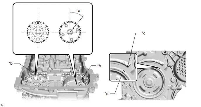
| *a | 39.5° | *b | Timing Mark |
| *c | "0" Timing Mark | *d | Groove |
(b) Turn the crankshaft pulley and align its groove with the "0" timing mark of the timing chain or belt cover sub-assembly.
Procedure1
(c) Check that the timing marks of the camshaft timing gear assembly and camshaft timing sprocket are at the positions shown in the illustration.
HINT:
If the timing marks are not as shown, turn the crankshaft one revolution clockwise.
OK:
Timing marks on camshaft timing gear assembly and camshaft timing sprocket are at the positions shown in the illustration.
HINT:
If the result is not as specified, check for mechanical malfunctions that may have affected the valve timing, such as a jumped tooth or stretching of the timing chain.
Post-procedure1
(d) None
| NG |

| GO TO STEP 33 |
|

| 18. | PERFORM ACTIVE TEST USING GTS (CONTROL THE EGR STEP POSITION) |
Pre-procedure1
(a) Put the engine in Inspection Mode (Maintenance Mode).
Powertrain > Hybrid Control > Utility| Tester Display |
|---|
| Inspection Mode |
(b) Start the engine and warm it up until the engine coolant temperature is 75°C (167°F) or higher.
HINT:
The A/C switch and all accessories should be off.
Procedure1
(c) Confirm that the value of Data List item Engine Independent is "Operate" then check the value of Intake Manifold Absolute Pressure while performing the Active Test.
Powertrain > Engine > Active Test| Active Test Display |
|---|
| Control the EGR Step Position |
| Data List Display |
|---|
| Intake Manifold Absolute Pressure |
| Engine Independent |
NOTICE:
- Do not leave the EGR valve open for 10 seconds or more during the Active Test.
- Be sure to return the EGR valve to step 0 when the Active Test is completed.
- Do not open the EGR valve 30 steps or more during the Active Test.
OK:
The value of Intake Manifold Absolute Pressure changes in response to the EGR step position when the value of Engine Independent is "Operate".
Standard:
| - | Control the EGR Step Position (Active Test) | |
|---|---|---|
| 0 Steps | 0 to 30 Steps | |
| Intake Manifold Absolute Pressure (Data List) | (EGR valve is fully closed) | Intake Manifold Absolute Pressure value is at least 10 kPa (1.45 psi) higher than when EGR valve is fully closed |
HINT:
- If the value of Data List item Engine Independent is "Not Opr" when the engine is idling, charge control is being performed. Perform the Active Test after charge control is complete ("Operate" is displayed).
- While performing the Active Test, if the increase in the value of Intake Manifold Absolute Pressure is small, the EGR valve assembly may be malfunctioning.
- Even if the EGR valve assembly is malfunctioning, rough idling or an increase in the value of Intake Manifold Absolute Pressure may occur while performing the Active Test. However, the amount that the value of Intake Manifold Absolute Pressure increases will be smaller than normal.
Post-procedure1
(d) None
| OK |

| GO TO STEP 36 |
|

| 19. | INSPECT EGR VALVE ASSEMBLY |
Pre-procedure1
(a) Remove the EGR valve assembly.
HINT:
Click here

Procedure1
(b) Check if the EGR valve is stuck open.
OK:
EGR valve is tightly closed.
Post-procedure1
(c) None
| OK |

| GO TO STEP 36 |
| NG |

| REPLACE EGR VALVE ASSEMBLY |
| 20. | CHECK INTAKE SYSTEM |
(a) Check the intake system for vacuum leaks.
Click here

OK:
No leaks from intake system.
HINT:
Perform "Inspection After Repair" after repairing or replacing the intake system.
Click here

| NG |

| REPAIR OR REPLACE INTAKE SYSTEM |
|

| 21. | CHECK FUEL PRESSURE |
Click here

| NG |

| GO TO STEP 43 |
|

| 22. | READ VALUE USING GTS (COOLANT TEMPERATURE) |
Pre-procedure1
(a) None
Procedure1
(b) Read the Data List twice, when the engine is both cold and warmed up.
Powertrain > Engine > Data List| Tester Display |
|---|
| Coolant Temperature |
Standard:
| GTS Display | Condition | Specified Condition |
|---|---|---|
| Coolant Temperature | Cold engine | Same as ambient air temperature |
| Warm engine | Between 75 and 100°C (167 and 212°F) |
Post-procedure1
(c) None
| NG |

| REPLACE ENGINE COOLANT TEMPERATURE SENSOR |
|

| 23. | READ VALUE USING GTS (INTAKE AIR TEMPERATURE) |
Pre-procedure1
(a) None
Procedure1
(b) According to the display on the GTS, read the Data List.
Powertrain > Engine > Data List| Tester Display |
|---|
| Intake Air Temperature |
OK:
Same as actual intake air temperature.
Post-procedure1
(c) None
| NG |

| REPLACE MASS AIR FLOW METER SUB-ASSEMBLY |
|

| 24. | READ VALUE USING GTS (MASS AIR FLOW SENSOR) |
Pre-procedure1
(a) Put the engine in Inspection Mode (Maintenance Mode).
Powertrain > Hybrid Control > Utility| Tester Display |
|---|
| Inspection Mode |
(b) Start the engine.
(c) Allow the engine to idle until Coolant Temperature reaches 75°C (167°F) or higher with with the A/C switch and all accessories off.
Powertrain > Engine > Data List| Tester Display |
|---|
| Coolant Temperature |
(d) Move the shift lever to P.
Procedure1
(e) Read Mass Air Flow Sensor with the engine speed at 2500 rpm.
Powertrain > Engine > Data List| Tester Display |
|---|
| Engine Speed |
| Mass Air Flow Sensor |
HINT:
During charge control, the engine speed is set at idle. Therefore, the engine speed will not increase when the accelerator pedal is depressed. In this case, read the Data List after charge control has completed.
| Result | Proceed to |
|---|---|
| The value of Mass Air Flow Sensor is between 4.5 and 8.5 gm/sec | A |
| None of the above conditions are met | B |
Post-procedure1
(f) None
| B |

| GO TO STEP 36 |
|

| 25. | CHECK VALVE TIMING (CHECK FOR LOOSE TIMING CHAIN AND JUMPED TEETH) |
Pre-procedure1
(a) Remove the cylinder head cover sub-assembly.

| *a | 39.5° | *b | Timing Mark |
| *c | "0" Timing Mark | *d | Groove |
(b) Turn the crankshaft pulley and align its groove with the "0" timing mark of the timing chain or belt cover sub-assembly.
Procedure1
(c) Check that the timing marks of the camshaft timing gear assembly and camshaft timing sprocket are at the positions shown in the illustration.
HINT:
If the timing marks are not as shown, turn the crankshaft one revolution clockwise.
OK:
Timing marks on camshaft timing gear assembly and camshaft timing sprocket are at the positions shown in the illustration.
HINT:
If the result is not as specified, check for mechanical malfunctions that may have affected the valve timing, such as a jumped tooth or stretching of the timing chain.
Post-procedure1
(d) None
| NG |

| GO TO STEP 33 |
|

| 26. | PERFORM ACTIVE TEST USING GTS (CONTROL THE EGR STEP POSITION) |
Pre-procedure1
(a) Put the engine in Inspection Mode (Maintenance Mode).
Powertrain > Hybrid Control > Utility| Tester Display |
|---|
| Inspection Mode |
(b) Start the engine and warm it up until the engine coolant temperature is 75°C (167°F) or higher.
HINT:
The A/C switch and all accessories should be off.
Procedure1
(c) Confirm that the value of Data List item Engine Independent is "Operate" then check the value of Intake Manifold Absolute Pressure while performing the Active Test.
Powertrain > Engine > Active Test| Active Test Display |
|---|
| Control the EGR Step Position |
| Data List Display |
|---|
| Intake Manifold Absolute Pressure |
| Engine Independent |
NOTICE:
- Do not leave the EGR valve open for 10 seconds or more during the Active Test.
- Be sure to return the EGR valve to step 0 when the Active Test is completed.
- Do not open the EGR valve 30 steps or more during the Active Test.
OK:
The value of Intake Manifold Absolute Pressure changes in response to the EGR step position when the value of Engine Independent is "Operate".
Standard:
| - | Control the EGR Step Position (Active Test) | |
|---|---|---|
| 0 Steps | 0 to 30 Steps | |
| Intake Manifold Absolute Pressure (Data List) | (EGR valve is fully closed) | Intake Manifold Absolute Pressure value is at least 10 kPa (1.45 psi) higher than when EGR valve is fully closed |
HINT:
- If the value of Data List item Engine Independent is "Not Opr" when the engine is idling, charge control is being performed. Perform the Active Test after charge control is complete ("Operate" is displayed).
- While performing the Active Test, if the increase in the value of Intake Manifold Absolute Pressure is small, the EGR valve assembly may be malfunctioning.
- Even if the EGR valve assembly is malfunctioning, rough idling or an increase in the value of Intake Manifold Absolute Pressure may occur while performing the Active Test. However, the amount that the value of Intake Manifold Absolute Pressure increases will be smaller than normal.
Post-procedure1
(d) None
| OK |

| GO TO STEP 28 |
|

| 27. | INSPECT EGR VALVE ASSEMBLY |
Pre-procedure1
(a) Remove the EGR valve assembly.
HINT:
Click here

Procedure1
(b) Check if the EGR valve is stuck open.
OK:
EGR valve is tightly closed.
Post-procedure1
(c) None
| NG |

| REPLACE EGR VALVE ASSEMBLY |
|

| 28. | INSPECT SPARK PLUG |
(a) Inspect the spark plug of the misfiring cylinder.
Click here

| NG |

| REPLACE SPARK PLUG |
|

| 29. | CHECK FOR SPARKS (SPARK TEST) |
Click here

HINT:
- If the result of the spark test is normal, proceed to the next step.
-
Perform "Inspection After Repair" after repairing or replacing the ignition system.
Click here

|

| 30. | CHECK CYLINDER COMPRESSION PRESSURE |
(a) Measure the cylinder compression pressure of the misfiring cylinder.
Click here

HINT:
Perform "Inspection After Repair" after repairing or replacing the engine assembly.
Click here

| NG |

| CHECK ENGINE TO DETERMINE CAUSE OF LOW COMPRESSION |
|

| 31. | CHECK TERMINAL VOLTAGE (#10, #20, #30 AND/OR #40) |
Pre-procedure1
(a) Disconnect the ECM connector.
(b) Turn the ignition switch ON.
Procedure1
(c) Measure the voltage according to the value(s) in the table below.
Standard Voltage:
 Click Location & Routing(C53,A91) Click Connector(C53) Click Connector(A91)
 | Tester Connection | Condition | Specified Condition | Result |
|---|---|---|---|
| C53-34 (#10) - A91-15 (E01) | Ignition switch ON | 11 to 14 V | V |
| C53-35 (#20) - A91-15 (E01) | Ignition switch ON | 11 to 14 V | V |
| C53-36 (#30) - A91-15 (E01) | Ignition switch ON | 11 to 14 V | V |
| C53-37 (#40) - A91-15 (E01) | Ignition switch ON | 11 to 14 V | V |
Post-procedure1
(d) None
| NG |

| CHECK FUEL INJECTOR CIRCUIT |
|

| 32. | CHECK FUEL INJECTOR ASSEMBLY |
(a) Check the fuel injector assembly (whether fuel volume is high or low, and whether injection pattern is poor).
Click here

| OK |

| GO TO STEP 36 |
| NG |

| REPLACE FUEL INJECTOR ASSEMBLY |
| 33. | CHECK ENGINE MECHANICAL SYSTEM |
(a) Check for mechanical malfunctions that affect the valve timing, such as a jumped tooth or stretching of the timing chain.
HINT:
Perform "Inspection After Repair" after repairing or replacing the engine mechanical system.
Click here

| NG |

| REPAIR OR REPLACE MALFUNCTIONING PARTS, COMPONENT AND AREA |
|

| 34. | CLEAR DTC |
Pre-procedure1
(a) None
Procedure1
(b) Clear the DTCs.
Powertrain > Engine > Clear DTCsPost-procedure1
(c) Turn the ignition switch off and wait for at least 30 seconds.
|

| 35. | CHECK WHETHER DTC OUTPUT RECURS (MISFIRE DTCS) |
Pre-procedure1
(a) Drive the Toyota Prius vehicle in accordance with the driving pattern described in Confirmation Driving Pattern.
Procedure1
(b) Check the DTC judgment result.
Powertrain > Engine > Utility| Tester Display |
|---|
| All Readiness |
(c) Input the DTC: P030000, P030027, P030085, P030100, P030200, P030300 or P030400.
| Result | Proceed to |
|---|---|
| NORMAL (DTCs are not output) | A |
| ABNORMAL (DTC P030000, P030027, P030085, P030100, P030200, P030300 and/or P030400 is output) | B |
Post-procedure1
(d) None
| A |

| CHECK FOR INTERMITTENT PROBLEMS |
|

| 36. | CHECK HARNESS AND CONNECTOR (MASS AIR FLOW METER SUB-ASSEMBLY CONNECTOR CONNECTION) |
(a) Check the connection and terminal contact pressure of connectors and wire harnesses between the mass air flow meter sub-assembly and ECM.
HINT:
-
Click here

- Repair any problems.
|

| 37. | CLEAR DTC |
Pre-procedure1
(a) None
Procedure1
(b) Clear the DTCs.
Powertrain > Engine > Clear DTCsPost-procedure1
(c) Turn the ignition switch off and wait for at least 30 seconds.
|

| 38. | CHECK WHETHER DTC OUTPUT RECURS (MISFIRE DTCS) |
Pre-procedure1
(a) Drive the Toyota Prius vehicle in accordance with the driving pattern described in Confirmation Driving Pattern.
Procedure1
(b) Check the DTC judgment result.
Powertrain > Engine > Utility| Tester Display |
|---|
| All Readiness |
(c) Input the DTC: P030000, P030027, P030085, P030100, P030200, P030300 or P030400.
| Result | Proceed to |
|---|---|
| NORMAL (DTCs are not output) | A |
| ABNORMAL (DTC P030000, P030027, P030085, P030100, P030200, P030300 and/or P030400 is output) | B |
Post-procedure1
(d) None
| A |

| END |
|

| 39. | CHECK HARNESS AND CONNECTOR (MASS AIR FLOW METER SUB-ASSEMBLY - ECM) |
Pre-procedure1
(a) Disconnect the mass air flow meter sub-assembly connector.
(b) Disconnect the ECM connector.
Procedure1
(c) Measure the resistance according to the value(s) in the table below.
Standard Resistance:
 Click Location & Routing(C27,C53) Click Connector(C27) Click Connector(C53)
 | Tester Connection | Condition | Specified Condition | Result |
|---|---|---|---|
| C27-4 (VCC) - C53-108 (VCVG) | Always | Below 1 Ω | Ω |
| C27-3 (FG) - C53-140 (VG) | Always | Below 1 Ω | Ω |
| C27-2 (E2G) - C53-107 (E2G) | Always | Below 1 Ω | Ω |
| C27-4 (VCC) or C53-108 (VCVG) - Body ground and other terminals | Always | 10 kΩ or higher | kΩ |
| C27-3 (FG) or C53-140 (VG) - Body ground and other terminals | Always | 10 kΩ or higher | kΩ |
| C27-2 (E2G) or C53-107 (E2G) - Body ground and other terminals | Always | 10 kΩ or higher | kΩ |
Post-procedure1
(d) None
| NG |

| REPAIR OR REPLACE HARNESS OR CONNECTOR |
|

| 40. | REPLACE MASS AIR FLOW METER SUB-ASSEMBLY |
HINT:
-
Click here

- If the results of the inspections performed in steps 16 and 24 (READ VALUE USING GTS (MASS AIR FLOW SENSOR)) indicated no problem, proceed to the next step without replacing the mass air flow meter sub-assembly.
|

| 41. | CLEAR DTC |
Pre-procedure1
(a) None
Procedure1
(b) Clear the DTCs.
Powertrain > Engine > Clear DTCsPost-procedure1
(c) Turn the ignition switch off and wait for at least 30 seconds.
|

| 42. | CONFIRM WHETHER MALFUNCTION HAS BEEN SUCCESSFULLY REPAIRED |
Pre-procedure1
(a) Drive the Toyota Prius vehicle in accordance with the driving pattern described in Confirmation Driving Pattern.
Procedure1
(b) Input the DTC: P030000, P030027, P030085, P030100, P030200, P030300 or P030400.
Powertrain > Engine > Utility| Tester Display |
|---|
| All Readiness |
(c) Check the DTC judgment result.
| Result | Proceed to |
|---|---|
| NORMAL (DTCs are not output) | A |
| ABNORMAL (DTC P030000, P030027, P030085, P030100, P030200, P030300 and/or P030400 is output) | B |
Post-procedure1
(d) None
| A |

| END |
| B |

| REPLACE ECM |
| 43. | INSPECT FUEL PUMP |
Click here

| OK |

| REPAIR OR REPLACE FUEL LINE |
| NG |

| REPLACE FUEL PUMP |
Knock Sensor 1 Bank 1 or Single Sensor Circuit Short to Ground (P032511)
DESCRIPTION
A flat-type knock control sensor (non-resonant type) has a structure that can detect vibrations between approximately 5 and 23 kHz.
The knock control sensor is installed to the engine block to detect engine knocking.
The knock control sensor contains a piezoelectric element which generates a voltage when it becomes deformed.
The voltage is generated when the engine block vibrates due to knocking. Any occurrence of engine knocking can be suppressed by delaying the ignition timing.
HINT:
When DTC P032511 is stored, the ECM enters fail-safe mode. During fail-safe mode, the ignition timing is delayed to its maximum retardation. Fail-safe mode continues until the ignition switch is turned off.
| DTC No. | Detection Item | DTC Detection Condition | Trouble Area | MIL | DTC Output from | Priority | Note |
|---|---|---|---|---|---|---|---|
| P032511 | Knock Sensor 1 Bank 1 or Single Sensor Circuit Short to Ground | The knock control sensor output voltage is less than 0.5 V for 1 second or more (1 trip detection logic). |
| Comes on | Engine | A | SAE Code: P0327 |
Reference: Inspection using an oscilloscope

HINT:
The correct waveform is as shown.
| ECM Terminal Name | Between KNK1 and EKNK |
| Tester Range | 1 V/DIV., 1 ms./DIV. |
| Condition | Engine speed maintained at 2500 rpm after warming up engine |
MONITOR DESCRIPTION
If the output voltage transmitted by the knock control sensor remains low for 1 second or more, the ECM interprets this as a malfunction in the sensor circuit, illuminates the MIL and stores this DTC.
MONITOR STRATEGY
| Frequency of Operation | Continuous |
CONFIRMATION DRIVING PATTERN
- Clear the DTCs (even if no DTCs are stored, perform the clear DTC procedure).
- Turn the ignition switch off and wait for at least 30 seconds.
- Turn the ignition switch ON.
-
Put the engine in Inspection Mode (Maintenance Mode).
Click here

- Start the engine and wait 5 minutes.
- Enter the following menus: Powertrain / Engine / Trouble Codes.
-
Read the pending DTCs.
HINT:
- If a pending DTC is output, the system is malfunctioning.
- If a pending DTC is not output, perform the following procedure.
- Enter the following menus: Powertrain / Engine / Utility / All Readiness.
- Input the DTC: P032511.
-
Check the DTC judgment result.
HINT:
- If the judgment result is NORMAL, the system is normal.
- If the judgment result is ABNORMAL, the system is malfunctioning.
- If the judgment result is INCOMPLETE, idle the engine for 5 minutes and check the DTC judgment result again.
WIRING DIAGRAM
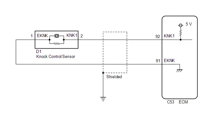
CAUTION / NOTICE / HINT
NOTICE:
-
Toyota Prius Vehicle Control History may be stored in the hybrid vehicle control ECU if the engine is malfunctioning. Certain vehicle condition information is recorded when Vehicle Control History is stored. Reading the vehicle conditions recorded in both the freeze frame data and Vehicle Control History can be useful for troubleshooting.
Click here

(Select Powertrain in Health Check and then check the time stamp data.)
-
If any "Engine Malfunction" Toyota Prius Vehicle Control History item has been stored in the hybrid vehicle control ECU, make sure to clear it. However, as all Vehicle Control History items are cleared simultaneously, if any Vehicle Control History items other than "Engine Malfunction" are stored, make sure to perform any troubleshooting for them before clearing Toyota Prius Vehicle Control History.
Click here

PROCEDURE
| 1. | CHECK TERMINAL VOLTAGE (POWER SOURCE OF KNOCK CONTROL SENSOR) |
Pre-procedure1
(a) Disconnect the knock control sensor connector.
(b) Turn the ignition switch ON.
Procedure1
(c) Measure the voltage according to the value(s) in the table below.
Standard Voltage:
 Click Location & Routing(D1) Click Connector(D1)
 | Tester Connection | Condition | Specified Condition | Result |
|---|---|---|---|
| D1-2 (KNK1) - D1-1 (EKNK) | Ignition switch ON | 4.5 to 5.5 V | V |
Post-procedure1
(d) None
| NG |

| GO TO STEP 3 |
|

| 2. | INSPECT KNOCK CONTROL SENSOR |
Click here

| OK |

| GO TO STEP 4 |
| NG |

| REPLACE KNOCK CONTROL SENSOR |
| 3. | CHECK HARNESS AND CONNECTOR (KNOCK CONTROL SENSOR - ECM) |
Pre-procedure1
(a) Disconnect the knock control sensor connector.
(b) Disconnect the ECM connector.
Procedure1
(c) Measure the resistance according to the value(s) in the table below.
Standard Resistance:
 Click Location & Routing(D1,C53) Click Connector(D1) Click Connector(C53)
 | Tester Connection | Condition | Specified Condition | Result |
|---|---|---|---|
| D1-2 (KNK1) or C53-92 (KNK1) - Body ground | Always | 10 kΩ or higher | kΩ |
Post-procedure1
(d) None
| NG |

| REPAIR OR REPLACE HARNESS OR CONNECTOR |
|

| 4. | CLEAR DTC |
Pre-procedure1
(a) None
Procedure1
(b) Clear the DTCs.
Powertrain > Engine > Clear DTCsPost-procedure1
(c) Turn the ignition switch off and wait for at least 30 seconds.
|

| 5. | CHECK WHETHER DTC OUTPUT RECURS (DTC P032511) |
Pre-procedure1
(a) Drive the Toyota Prius vehicle in accordance with the driving pattern described in Confirmation Driving Pattern.
Procedure1
(b) Read the DTCs.
Powertrain > Engine > Trouble Codes| Result | Proceed to |
|---|---|
| DTCs are not output | A |
| P032511 is output | B |
Post-procedure1
(c) None
| A |

| CHECK FOR INTERMITTENT PROBLEMS |
| B |

| REPLACE ECM |
Knock Sensor 1 Bank 1 or Single Sensor Circuit Short to Battery or Open (P032515)
DESCRIPTION
Refer to DTC P032511.
Click here

HINT:
When DTC P032515 is stored, the ECM enters fail-safe mode. During fail-safe mode, the ignition timing is delayed to its maximum retardation. Fail-safe mode continues until the ignition switch is turned off.
| DTC No. | Detection Item | DTC Detection Condition | Trouble Area | MIL | DTC Output from | Priority | Note |
|---|---|---|---|---|---|---|---|
| P032515 | Knock Sensor 1 Bank 1 or Single Sensor Circuit Short to Battery or Open | The knock control sensor output voltage is higher than 4.5 V for 1 second or more (1 trip detection logic). |
| Comes on | Engine | A | SAE Code: P0328 |
Reference: Inspection using an oscilloscope.
Click here

MONITOR DESCRIPTION
If the output voltage transmitted by the knock control sensor remains high for 1 second or more, the ECM interprets this as a malfunction in the sensor circuit, illuminates the MIL and stores this DTC.
MONITOR STRATEGY
| Frequency of Operation | Continuous |
CONFIRMATION DRIVING PATTERN
- Clear the DTCs (even if no DTCs are stored, perform the clear DTC procedure).
- Turn the ignition switch off and wait for at least 30 seconds.
- Turn the ignition switch ON.
-
Put the engine in Inspection Mode (Maintenance Mode).
Click here

- Start the engine and wait 5 minutes.
- Enter the following menus: Powertrain / Engine / Trouble Codes.
-
Read the pending DTCs.
HINT:
- If a pending DTC is output, the system is malfunctioning.
- If a pending DTC is not output, perform the following procedure.
- Enter the following menus: Powertrain / Engine / Utility / All Readiness.
- Input the DTC: P032515.
-
Check the DTC judgment result.
HINT:
- If the judgment result is NORMAL, the system is normal.
- If the judgment result is ABNORMAL, the system is malfunctioning.
- If the judgment result is INCOMPLETE, idle the engine for 5 minutes and check the DTC judgment result again.
WIRING DIAGRAM
Refer to DTC P032511.
Click here

CAUTION / NOTICE / HINT
NOTICE:
-
Toyota Prius Vehicle Control History may be stored in the hybrid vehicle control ECU if the engine is malfunctioning. Certain vehicle condition information is recorded when Vehicle Control History is stored. Reading the vehicle conditions recorded in both the freeze frame data and Vehicle Control History can be useful for troubleshooting.
Click here

(Select Powertrain in Health Check and then check the time stamp data.)
-
If any "Engine Malfunction" Toyota Prius Vehicle Control History item has been stored in the hybrid vehicle control ECU, make sure to clear it. However, as all Vehicle Control History items are cleared simultaneously, if any Vehicle Control History items other than "Engine Malfunction" are stored, make sure to perform any troubleshooting for them before clearing Toyota Prius Vehicle Control History.
Click here

PROCEDURE
| 1. | CHECK TERMINAL VOLTAGE (POWER SOURCE OF KNOCK CONTROL SENSOR) |
Pre-procedure1
(a) Disconnect the knock control sensor connector.
(b) Turn the ignition switch ON.
Procedure1
(c) Measure the voltage according to the value(s) in the table below.
Standard Voltage:
 Click Location & Routing(D1) Click Connector(D1)
 | Tester Connection | Condition | Specified Condition | Result |
|---|---|---|---|
| D1-2 (KNK1) - D1-1 (EKNK) | Ignition switch ON | 4.5 to 5.5 V | V |
Post-procedure1
(d) None
| NG |

| GO TO STEP 3 |
|

| 2. | INSPECT KNOCK CONTROL SENSOR |
Click here

| OK |

| GO TO STEP 4 |
| NG |

| REPLACE KNOCK CONTROL SENSOR |
| 3. | CHECK HARNESS AND CONNECTOR (KNOCK CONTROL SENSOR - ECM) |
Pre-procedure1
(a) Disconnect the knock control sensor connector.
(b) Disconnect the ECM connector.
Procedure1
(c) Measure the resistance according to the value(s) in the table below.
Standard Resistance:
 Click Location & Routing(D1,C53) Click Connector(D1) Click Connector(C53)
 | Tester Connection | Condition | Specified Condition | Result |
|---|---|---|---|
| D1-2 (KNK1) - C53-92 (KNK1) | Always | Below 1 Ω | Ω |
| D1-1 (EKNK) - C53-91 (EKNK) | Always | Below 1 Ω | Ω |
| D1-2 (KNK1) or C53-92 (KNK1) - Other terminals | Always | 10 kΩ or higher | kΩ |
Post-procedure1
(d) None
| NG |

| REPAIR OR REPLACE HARNESS OR CONNECTOR |
|

| 4. | CLEAR DTC |
Pre-procedure1
(a) None
Procedure1
(b) Clear the DTCs.
Powertrain > Engine > Clear DTCsPost-procedure1
(c) Turn the ignition switch off and wait for at least 30 seconds.
|

| 5. | CHECK WHETHER DTC OUTPUT RECURS (DTC P032515) |
Pre-procedure1
(a) Drive the Toyota Prius vehicle in accordance with the driving pattern described in Confirmation Driving Pattern.
Procedure1
(b) Read the DTCs.
Powertrain > Engine > Trouble Codes| Result | Proceed to |
|---|---|
| DTCs are not output | A |
| P032515 is output | B |
Post-procedure1
(c) None
| A |

| CHECK FOR INTERMITTENT PROBLEMS |
| B |

| REPLACE ECM |
Crankshaft Position Sensor "A" Circuit Short to Ground (P033511)
DESCRIPTION
The crankshaft position sensor system consists of a crankshaft position sensor plate and Magneto Resistance Element (MRE) type sensor. The crankshaft position sensor plate has 34 teeth at 10° intervals (2 teeth are missing for detecting top dead center), and is installed on the crankshaft. The crankshaft position sensor generates 34 signals per crankshaft revolution. The ECM uses the crankshaft position sensor signal (NE signal) to detect the crankshaft position and engine speed.
| DTC No. | Detection Item | DTC Detection Condition | Trouble Area | MIL | DTC Output from | Priority | Note |
|---|---|---|---|---|---|---|---|
| P033511 | Crankshaft Position Sensor "A" Circuit Short to Ground | Diagnosis condition:
Abnormal condition:
Malfunction time:
Trip logic:
Detection conditions:
Sensors/components used for detection (Main):
Sensors/components used for detection (Related):
|
| Comes on | Engine | A | SAE Code: P0337 |
-
Reference: Inspection using an oscilloscope.
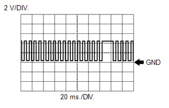
HINT:
The correct waveform is as shown.
ECM Terminal Name
Between NE and NE-
Tester Range
2 V/DIV., 20 ms./DIV.
Condition
Idling with warm engine
MONITOR DESCRIPTION
When the ignition switch is turned ON and the output voltage of the crankshaft position sensor is less than 0.3 V for 4 seconds or more, the ECM determines that the crankshaft position sensor circuit is malfunctioning and illuminates the MIL and stores a DTC.
MONITOR STRATEGY
| Required Sensors/Components (Main) | Crankshaft position sensor |
| Required Sensors/Components (Related) | Camshaft position sensor |
| Frequency of Operation | Continuous |
CONFIRMATION DRIVING PATTERN
- Clear the DTCs (even if no DTCs are stored, perform the clear DTC procedure).
- Turn the ignition switch off and wait for at least 30 seconds.
- Turn the ignition switch ON.
- Wait 5 seconds or more.
- Enter the following menus: Powertrain / Engine / Trouble Codes.
-
Read the pending DTCs.
HINT:
- If a pending DTC is output, the system is malfunctioning.
- If a pending DTC is not output, perform the following procedure.
- Enter the following menus: Powertrain / Engine / Utility / All Readiness.
- Proceed to the next screen and enter the DTC to be checked.
-
Check the DTC judgment result.
HINT:
- If the judgment result is NORMAL, the system is normal.
- If the judgment result is ABNORMAL, the system has a malfunction.
WIRING DIAGRAM
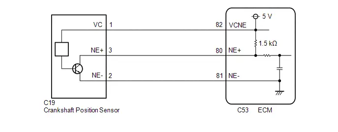
CAUTION / NOTICE / HINT
NOTICE:
-
Toyota Prius Vehicle Control History may be stored in the hybrid vehicle control ECU assembly if the engine is malfunctioning. Certain vehicle condition information is recorded when Vehicle Control History is stored. Reading the vehicle conditions recorded in both the Freeze Frame Data and Vehicle Control History can be useful for troubleshooting.
Click here

(Select Powertrain in Health Check and then check the time stamp data.)
-
If any "Engine Malfunction" Toyota Prius Vehicle Control History item has been stored in the hybrid vehicle control ECU assembly, make sure to clear it. However, as all Vehicle Control History items are cleared simultaneously, if any Vehicle Control History items other than "Engine Malfunction" are stored, make sure to perform any troubleshooting for them before clearing Toyota Prius Vehicle Control History.
Click here

HINT:
The engine speed can be checked by using the GTS. To perform the check, follow the procedures below:
- Enter the following menus: Powertrain / Engine / Data List / Engine Speed.
- Start the engine.
- The engine speed may be indicated as zero despite the engine running normally. This is caused by a lack of NE signals from the crankshaft position sensor. Alternatively, the engine speed may be indicated as lower than the actual engine speed if the crankshaft position sensor output voltage is insufficient.
PROCEDURE
| 1. | CLEAR DTC |
Pre-procedure1
(a) None
Procedure1
(b) Clear the DTCs.
Powertrain > Engine > Clear DTCsPost-procedure1
(c) Turn the ignition switch off and wait for at least 30 seconds.
|

| 2. | CHECK DTC OUTPUT (DTC P033511 OR P033515) |
Pre-procedure1
HINT:
Make sure that the connector is properly connected. If it is not, securely connect it and check for DTCs again.
(a) Disconnect the crankshaft position sensor connector.
(b) Drive the Toyota Prius vehicle in accordance with the driving pattern described in Confirmation Driving Pattern.
Procedure1
(c) Read the DTCs.
Powertrain > Engine > Trouble CodesHINT:
When the ECM, wire harnesses and connectors are normal, DTC P033515 will be stored when the connector of the sensor is disconnected.
| Result | Proceed to |
|---|---|
| P033515 is output | A |
| P033511 is output | B |
Post-procedure1
(d) None
| A |

| REPLACE CRANKSHAFT POSITION SENSOR |
|

| 3. | CHECK HARNESS AND CONNECTOR (CRANKSHAFT POSITION SENSOR - ECM) |
Pre-procedure1
(a) Disconnect the crankshaft position sensor connector.
(b) Disconnect the ECM connector.
Procedure1
(c) Measure the resistance according to the value(s) in the table below.
Standard Resistance:
 Click Location & Routing(C19,C53) Click Connector(C19) Click Connector(C53)
 | Tester Connection | Condition | Specified Condition | Result |
|---|---|---|---|
| C19-3 (NE ) or C53-80 (NE ) - Body ground and other terminals | Always | 10 kΩ or higher | kΩ |
| C19-2 (NE-) or C53-81 (NE-) - Body ground and other terminals | Always | 10 kΩ or higher | kΩ |
Post-procedure1
(d) None
| OK |

| REPLACE ECM |
| NG |

| REPAIR OR REPLACE HARNESS OR CONNECTOR |
Crankshaft Position Sensor "A" Circuit Short to Battery or Open (P033515)
DESCRIPTION
Refer to DTC P033511.
Click here

| DTC No. | Detection Item | DTC Detection Condition | Trouble Area | MIL | DTC Output from | Priority | Note |
|---|---|---|---|---|---|---|---|
| P033515 | Crankshaft Position Sensor "A" Circuit Short to Battery or Open | Diagnosis condition:
Abnormal condition:
Malfunction time:
Trip logic:
Detection conditions:
Sensors/components used for detection (Main):
Sensors/components used for detection (Related):
|
| Comes on | Engine | A | SAE Code: P0338 |
-
Reference: Inspection using an oscilloscope.
Click here

MONITOR DESCRIPTION
When the ignition switch is turned ON and the output voltage of the crankshaft position sensor is higher than 4.7 V for 4 seconds or more, the ECM determines that the crankshaft position sensor circuit is malfunctioning and illuminates the MIL and stores a DTC.
MONITOR STRATEGY
| Required Sensors/Components (Main) | Crankshaft position sensor |
| Required Sensors/Components (Related) | Camshaft position sensor |
| Frequency of Operation | Continuous |
CONFIRMATION DRIVING PATTERN
Refer to DTC P033511.
Click here

WIRING DIAGRAM
Refer to DTC P033511.
Click here

CAUTION / NOTICE / HINT
NOTICE:
-
Toyota Prius Vehicle Control History may be stored in the hybrid vehicle control ECU assembly if the engine is malfunctioning. Certain vehicle condition information is recorded when Vehicle Control History is stored. Reading the vehicle conditions recorded in both the Freeze Frame Data and Vehicle Control History can be useful for troubleshooting.
Click here

(Select Powertrain in Health Check and then check the time stamp data.)
-
If any "Engine Malfunction" Toyota Prius Vehicle Control History item has been stored in the hybrid vehicle control ECU assembly, make sure to clear it. However, as all Vehicle Control History items are cleared simultaneously, if any Vehicle Control History items other than "Engine Malfunction" are stored, make sure to perform any troubleshooting for them before clearing Toyota Prius Vehicle Control History.
Click here

HINT:
The engine speed can be checked by using the GTS. To perform the check, follow the procedures below:
- Enter the following menus: Powertrain / Engine / Data List / Engine Speed.
- Start the engine.
- The engine speed may be indicated as zero despite the engine running normally. This is caused by a lack of NE signals from the crankshaft position sensor. Alternatively, the engine speed may be indicated as lower than the actual engine speed if the crankshaft position sensor output voltage is insufficient.
PROCEDURE
| 1. | CHECK TERMINAL VOLTAGE (CRANKSHAFT POSITION SENSOR) |
HINT:
Make sure that the connector is properly connected. If it is not, securely connect it and check for DTCs again.
Pre-procedure1
(a) Disconnect the crankshaft position sensor connector.
(b) Turn the ignition switch ON.
Procedure1
(c) Measure the voltage according to the value(s) in the table below.
Standard Voltage:
 Click Location & Routing(C19) Click Connector(C19)
 | Tester Connection | Condition | Specified Condition |
|---|---|---|
| C19-1 (VC) - Body ground | Ignition switch ON | 4.5 to 5.5 V |
| Result | Proceed to |
|---|---|
| Higher than 5.5 V | A |
| 4.5 to 5.5 V | B |
| Below 4.5 V | C |
Post-procedure1
(d) None
| B |

| GO TO STEP 3 |
| C |

| GO TO STEP 10 |
|

| 2. | CHECK HARNESS AND CONNECTOR (CRANKSHAFT POSITION SENSOR - ECM) |
Pre-procedure1
(a) Disconnect the crankshaft position sensor connector.
(b) Disconnect the ECM connector.
Procedure1
(c) Measure the resistance according to the value(s) in the table below.
Standard Resistance:
 Click Location & Routing(C19,C53) Click Connector(C19) Click Connector(C53)
 | Tester Connection | Condition | Specified Condition | Result |
|---|---|---|---|
| C19-1 (VC) or C53-82 (VCNE) - Other terminals | Always | 10 kΩ or higher | kΩ |
Post-procedure1
(d) None
| OK |

| REPLACE ECM |
| NG |

| REPAIR OR REPLACE HARNESS OR CONNECTOR |
| 3. | CHECK TERMINAL VOLTAGE (CRANKSHAFT POSITION SENSOR) |
Pre-procedure1
(a) Disconnect the crankshaft position sensor connector.
(b) Turn the ignition switch ON.
Procedure1
(c) Measure the voltage according to the value(s) in the table below.
Standard Voltage:
 Click Location & Routing(C19) Click Connector(C19)
 | Tester Connection | Condition | Specified Condition |
|---|---|---|
| C19-3 (NE ) - Body ground | Ignition switch ON | 3.0 to 5.0 V |
| Result | Proceed to |
|---|---|
| Higher than 5.0 V | A |
| 3.0 to 5.0 V | B |
| Below 3.0 V | C |
Post-procedure1
(d) None
| B |

| GO TO STEP 5 |
| C |

| GO TO STEP 9 |
|

| 4. | CHECK HARNESS AND CONNECTOR (CRANKSHAFT POSITION SENSOR - ECM) |
Pre-procedure1
(a) Disconnect the crankshaft position sensor connector.
(b) Disconnect the ECM connector.
Procedure1
(c) Measure the resistance according to the value(s) in the table below.
Standard Resistance:
 Click Location & Routing(C19,C53) Click Connector(C19) Click Connector(C53)
 | Tester Connection | Condition | Specified Condition | Result |
|---|---|---|---|
| C19-3 (NE ) or C53-80 (NE ) - Other terminals | Always | 10 kΩ or higher | kΩ |
Post-procedure1
(d) None
| OK |

| REPLACE ECM |
| NG |

| REPAIR OR REPLACE HARNESS OR CONNECTOR |
| 5. | CHECK HARNESS AND CONNECTOR (CRANKSHAFT POSITION SENSOR - BODY GROUND) |
Pre-procedure1
(a) Disconnect the crankshaft position sensor connector.
Procedure1
(b) Measure the resistance according to the value(s) in the table below.
Standard Resistance:
 Click Location & Routing(C19) Click Connector(C19)
 | Tester Connection | Condition | Specified Condition | Result |
|---|---|---|---|
| C19-2 (NE-) - Body ground | Always | Below 1 Ω | Ω |
Post-procedure1
(c) None
| NG |

| GO TO STEP 8 |
|

| 6. | CHECK INTERNAL RESISTANCE (ECM) |
Pre-procedure1
(a) Turn the ignition switch off.
(b) Disconnect the crankshaft position sensor connector.
Procedure1
(c) Measure the resistance according to the value(s) in the table below.
Standard Resistance:
 Click Location & Routing(C19) Click Connector(C19)
 | Tester Connection | Condition | Specified Condition | Result |
|---|---|---|---|
| C19-1 (VC) - C19-3 (NE ) | Ignition switch off | 1.425 to 1.575 kΩ | kΩ |
HINT:
As voltage is still supplied to the ECM after the ignition switch is turned off, this check cannot be performed correctly during the shut-down process.
Post-procedure1
(d) None
| OK |

| REPLACE CRANKSHAFT POSITION SENSOR |
|

| 7. | CHECK HARNESS AND CONNECTOR (CRANKSHAFT POSITION SENSOR - ECM) |
Pre-procedure1
(a) Disconnect the crankshaft position sensor connector.
(b) Disconnect the ECM connector.
Procedure1
(c) Measure the resistance according to the value(s) in the table below.
Standard Resistance:
 Click Location & Routing(C19,C53) Click Connector(C19) Click Connector(C53)
 | Tester Connection | Condition | Specified Condition | Result |
|---|---|---|---|
| C19-1 (VC) - C19-3 (NE ) or C53-82 (VCNE) - C53-80 (NE ) | Always | 10 kΩ or higher | kΩ |
Post-procedure1
(d) None
| OK |

| REPLACE ECM |
| NG |

| REPAIR OR REPLACE HARNESS OR CONNECTOR |
| 8. | CHECK HARNESS AND CONNECTOR (CRANKSHAFT POSITION SENSOR - ECM) |
Pre-procedure1
(a) Disconnect the crankshaft position sensor connector.
(b) Disconnect the ECM connector.
Procedure1
(c) Measure the resistance according to the value(s) in the table below.
Standard Resistance:
 Click Location & Routing(C19,C53) Click Connector(C19) Click Connector(C53)
 | Tester Connection | Condition | Specified Condition | Result |
|---|---|---|---|
| C19-2 (NE-) - C53-81 (NE-) | Always | Below 1 Ω | Ω |
Post-procedure1
(d) None
| OK |

| REPLACE ECM |
| NG |

| REPAIR OR REPLACE HARNESS OR CONNECTOR |
| 9. | CHECK HARNESS AND CONNECTOR (CRANKSHAFT POSITION SENSOR - ECM) |
Pre-procedure1
(a) Disconnect the crankshaft position sensor connector.
(b) Disconnect the ECM connector.
Procedure1
(c) Measure the resistance according to the value(s) in the table below.
Standard Resistance:
 Click Location & Routing(C19,C53) Click Connector(C19) Click Connector(C53)
 | Tester Connection | Condition | Specified Condition | Result |
|---|---|---|---|
| C19-3 (NE ) - C53-80 (NE ) | Always | Below 1 Ω | Ω |
Post-procedure1
(d) None
| OK |

| REPLACE ECM |
| NG |

| REPAIR OR REPLACE HARNESS OR CONNECTOR |
| 10. | CHECK HARNESS AND CONNECTOR (CRANKSHAFT POSITION SENSOR - ECM) |
Pre-procedure1
(a) Disconnect the crankshaft position sensor connector.
(b) Disconnect the ECM connector.
Procedure1
(c) Measure the resistance according to the value(s) in the table below.
Standard Resistance:
 Click Location & Routing(C19,C53) Click Connector(C19) Click Connector(C53)
 | Tester Connection | Condition | Specified Condition | Result |
|---|---|---|---|
| C19-1 (VC) - C53-82 (VCNE) | Always | Below 1 Ω | Ω |
Post-procedure1
(d) None
| OK |

| REPLACE ECM |
| NG |

| REPAIR OR REPLACE HARNESS OR CONNECTOR |
Crankshaft Position Sensor "A" Signal Stuck in Range (P03352A)
DESCRIPTION
Refer to DTC P033511.
Click here

| DTC No. | Detection Item | DTC Detection Condition | Trouble Area | MIL | DTC Output from | Priority | Note |
|---|---|---|---|---|---|---|---|
| P03352A | Crankshaft Position Sensor "A" Signal Stuck in Range | Diagnosis condition:
Abnormal condition:
Malfunction time:
Trip logic:
Detection conditions:
Sensors/components used for detection (Main):
Sensors/components used for detection (Related):
|
| Comes on | Engine | A | SAE Code: P0335 |
-
Reference: Inspection using an oscilloscope.
Click here

MONITOR DESCRIPTION
When the engine is cranking and no crankshaft position sensor signal is received for 4.7 seconds or more, the ECM determines that the crankshaft position sensor circuit is malfunctioning and illuminates the MIL and stores a DTC.
MONITOR STRATEGY
| Required Sensors/Components (Main) | Crankshaft position sensor |
| Required Sensors/Components (Related) | Camshaft position sensor |
| Frequency of Operation | Continuous |
CONFIRMATION DRIVING PATTERN
- Clear the DTCs (even if no DTCs are stored, perform the clear DTC procedure).
- Turn the ignition switch off and wait for at least 30 seconds.
- Start the engine [A].
- Idle the engine for 20 seconds or more [B].
- Enter the following menus: Powertrain / Engine / Trouble Codes [C].
-
Read the pending DTCs.
HINT:
- If a pending DTC is output, the system is malfunctioning.
- If a pending DTC is not output, perform the following procedure.
- Enter the following menus: Powertrain / Engine / Utility / All Readiness.
- Proceed to the next screen and enter the DTC to be checked.
-
Check the DTC judgment result.
HINT:
- If the judgment result is NORMAL, the system is normal.
- If the judgment result is ABNORMAL, the system has a malfunction.
- If the judgment result is INCOMPLETE, perform steps [A] through [C] again.
WIRING DIAGRAM
Refer to DTC P033511.
Click here

CAUTION / NOTICE / HINT
NOTICE:
-
Toyota Prius Vehicle Control History may be stored in the hybrid vehicle control ECU assembly if the engine is malfunctioning. Certain vehicle condition information is recorded when Vehicle Control History is stored. Reading the vehicle conditions recorded in both the Freeze Frame Data and Vehicle Control History can be useful for troubleshooting.
Click here

(Select Powertrain in Health Check and then check the time stamp data.)
-
If any "Engine Malfunction" Toyota Prius Vehicle Control History item has been stored in the hybrid vehicle control ECU assembly, make sure to clear it. However, as all Vehicle Control History items are cleared simultaneously, if any Vehicle Control History items other than "Engine Malfunction" are stored, make sure to perform any troubleshooting for them before clearing Toyota Prius Vehicle Control History.
Click here

HINT:
- If no problem is found by this diagnostic troubleshooting procedure, check for problems by referring to the engine mechanical section.
-
The engine speed can be checked by using the GTS. To perform the check, follow the procedures below:
- Enter the following menus: Powertrain / Engine / Data List / Engine Speed.
- Start the engine.
- The engine speed may be indicated as zero despite the engine running normally. This is caused by a lack of NE signals from the crankshaft position sensor. Alternatively, the engine speed may be indicated as lower than the actual engine speed if the crankshaft position sensor output voltage is insufficient.
PROCEDURE
| 1. | CHECK TERMINAL VOLTAGE AND INTERNAL RESISTANCE (CRANKSHAFT POSITION SENSOR AND ECM) |
HINT:
Make sure that the connector is properly connected. If it is not, securely connect it and check for DTCs again.
Pre-procedure1
(a) Disconnect the crankshaft position sensor connector.
(b) Turn the ignition switch ON.
Procedure1
(c) Measure the voltage according to the value(s) in the table below.
Standard Voltage:
 Click Location & Routing(C19) Click Connector(C19)
 | Tester Connection | Condition | Specified Condition | Result |
|---|---|---|---|
| C19-1 (VC) - Body ground | Ignition switch ON | 4.5 to 5.5 V | V |
| C19-3 (NE ) - Body ground | Ignition switch ON | 3.0 to 5.0 V | V |
Post-procedure1
(d) Turn the ignition switch off.
Pre-procedure2
(e) None
Procedure2
(f) Measure the resistance according to the value(s) in the table below.
Standard Resistance:
 Click Location & Routing(C19) Click Connector(C19)
 | Tester Connection | Condition | Specified Condition | Result |
|---|---|---|---|
| C19-2 (NE-) - Body ground | Ignition switch off | Below 1 Ω | Ω |
Post-procedure2
(g) None
| NG |

| GO TO STEP 4 |
|

| 2. | INSPECT CRANKSHAFT POSITION SENSOR |
Pre-procedure1
(a) Remove the crankshaft position sensor.
HINT:
Click here

Procedure1
(b) Confirm that there is no oil on the connecting parts of the crankshaft position sensor connector.
OK:
There is no oil on the connecting parts of the crankshaft position sensor connector
Post-procedure1
(c) None
| NG |

| REPLACE CRANKSHAFT POSITION SENSOR |
|

| 3. | INSPECT CRANKSHAFT POSITION SENSOR |
Pre-procedure1
| (a) Disconnect the crankshaft position sensor connector. |
|

Procedure1
(b) Measure the resistance according to the value(s) in the table below.
Standard Resistance:
| Tester Connection | Condition | Specified Condition | Result |
|---|---|---|---|
| 1 (VC) - 3 (NE ) | Always | 10 kΩ or higher | kΩ |
| 1 (VC) - 2 (NE-) | Always | 10 kΩ or higher | kΩ |
| 3 (NE ) - 2 (NE-) | Always | 10 kΩ or higher | kΩ |
Post-procedure1
(c) None
| OK |

| REPLACE ECM |
| NG |

| REPLACE CRANKSHAFT POSITION SENSOR |
| 4. | CHECK HARNESS AND CONNECTOR (CRANKSHAFT POSITION SENSOR - ECM) |
Pre-procedure1
(a) Disconnect the crankshaft position sensor connector.
(b) Disconnect the ECM connector.
Procedure1
(c) Measure the resistance according to the value(s) in the table below.
Standard Resistance:
 Click Location & Routing(C19,C53) Click Connector(C19) Click Connector(C53)
 | Tester Connection | Condition | Specified Condition | Result |
|---|---|---|---|
| C19-1 (VC) - C53-82 (VCNE) | Always | Below 1 Ω | Ω |
| C19-3 (NE ) - C53-80 (NE ) | Always | Below 1 Ω | Ω |
| C19-2 (NE-) - C53-81 (NE-) | Always | Below 1 Ω | Ω |
| C19-1 (VC) or C53-82 (VCNE) - Body ground and other terminals | Always | 10 kΩ or higher | kΩ |
| C19-3 (NE ) or C53-80 (NE ) - Body ground and other terminals | Always | 10 kΩ or higher | kΩ |
| C19-2 (NE-) or C53-81 (NE-) - Body ground and other terminals | Always | 10 kΩ or higher | kΩ |
Post-procedure1
(d) None
| OK |

| REPLACE ECM |
| NG |

| REPAIR OR REPLACE HARNESS OR CONNECTOR |
Crankshaft Position Sensor "A" No Signal (P033531)
DESCRIPTION
Refer to DTC P033511.
Click here

| DTC No. | Detection Item | DTC Detection Condition | Trouble Area | MIL | DTC Output from | Priority | Note |
|---|---|---|---|---|---|---|---|
| P033531 | Crankshaft Position Sensor "A" No Signal | Diagnosis condition:
Abnormal condition:
Malfunction time:
Trip logic:
Detection conditions:
Sensors/components used for detection (Main):
Sensors/components used for detection (Related):
|
| Comes on | Engine | B | SAE Code: P0335 |
-
Reference: Inspection using an oscilloscope.
Click here

MONITOR DESCRIPTION
When the engine speed fluctuates abnormally during engine stall judgement, the ECM determines that the crankshaft position sensor circuit is malfunctioning and illuminates the MIL and stores a DTC.(Under normal circumstances, the engine speed gradually decreases.)
MONITOR STRATEGY
| Required Sensors/Components (Main) | Crankshaft position sensor |
| Required Sensors/Components (Related) | Camshaft position sensor |
| Frequency of Operation | Continuous |
CONFIRMATION DRIVING PATTERN
Refer to DTC P03352A.
Click here

WIRING DIAGRAM
Refer to DTC P033511.
Click here

CAUTION / NOTICE / HINT
NOTICE:
-
Toyota Prius Vehicle Control History may be stored in the hybrid vehicle control ECU assembly if the engine is malfunctioning. Certain vehicle condition information is recorded when Vehicle Control History is stored. Reading the vehicle conditions recorded in both the Freeze Frame Data and Vehicle Control History can be useful for troubleshooting.
Click here

(Select Powertrain in Health Check and then check the time stamp data.)
-
If any "Engine Malfunction" Toyota Prius Vehicle Control History item has been stored in the hybrid vehicle control ECU assembly, make sure to clear it. However, as all Vehicle Control History items are cleared simultaneously, if any Vehicle Control History items other than "Engine Malfunction" are stored, make sure to perform any troubleshooting for them before clearing Toyota Prius Vehicle Control History.
Click here

HINT:
- If no problem is found by this diagnostic troubleshooting procedure, check for problems by referring to the engine mechanical section.
-
The engine speed can be checked by using the GTS. To perform the check, follow the procedures below:
- Enter the following menus: Powertrain / Engine / Data List / Engine Speed.
- Start the engine.
- The engine speed may be indicated as zero despite the engine running normally. This is caused by a lack of NE signals from the crankshaft position sensor. Alternatively, the engine speed may be indicated as lower than the actual engine speed if the crankshaft position sensor output voltage is insufficient.
PROCEDURE
| 1. | CHECK DTC OUTPUT (DTC P033531 AND P033511 OR P033515) |
(a) Read the DTCs.
Powertrain > Engine > Trouble Codes| Result | Proceed to |
|---|---|
| P033531 and P033511 are output | A |
| P033531 and P033515 are output | B |
| P033531 is output | C |
HINT:
If DTC P033511 or P033515 is output, perform troubleshooting for it first.
| A |

| GO TO DTC CHART |
| B |

| GO TO DTC CHART |
|

| 2. | CHECK TERMINAL VOLTAGE AND INTERNAL RESISTANCE (CRANKSHAFT POSITION SENSOR AND ECM) |
HINT:
Make sure that the connector is properly connected. If it is not, securely connect it and check for DTCs again.
Pre-procedure1
(a) Disconnect the crankshaft position sensor connector.
(b) Turn the ignition switch ON.
Procedure1
(c) Measure the voltage according to the value(s) in the table below.
Standard Voltage:
 Click Location & Routing(C19) Click Connector(C19)
 | Tester Connection | Condition | Specified Condition | Result |
|---|---|---|---|
| C19-1 (VC) - Body ground | Ignition switch ON | 4.5 to 5.5 V | V |
| C19-3 (NE ) - Body ground | Ignition switch ON | 3.0 to 5.0 V | V |
Post-procedure1
(d) Turn the ignition switch off.
Pre-procedure2
(e) None
Procedure2
(f) Measure the resistance according to the value(s) in the table below.
Standard Resistance:
 Click Location & Routing(C19) Click Connector(C19)
 | Tester Connection | Condition | Specified Condition | Result |
|---|---|---|---|
| C19-2 (NE-) - Body ground | Ignition switch off | Below 1 Ω | Ω |
Post-procedure2
(g) None
| NG |

| GO TO STEP 5 |
|

| 3. | INSPECT CRANKSHAFT POSITION SENSOR |
Pre-procedure1
(a) Remove the crankshaft position sensor.
HINT:
Click here

Procedure1
(b) Confirm that there is no oil on the connecting parts of the crankshaft position sensor connector.
OK:
There is no oil on the connecting parts of the crankshaft position sensor connector
Post-procedure1
(c) None
| NG |

| REPLACE CRANKSHAFT POSITION SENSOR |
|

| 4. | INSPECT CRANKSHAFT POSITION SENSOR |
Pre-procedure1
| (a) Disconnect the crankshaft position sensor connector. |
|
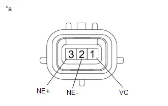
Procedure1
(b) Measure the resistance according to the value(s) in the table below.
Standard Resistance:
| Tester Connection | Condition | Specified Condition | Result |
|---|---|---|---|
| 1 (VC) - 3 (NE ) | Always | 10 kΩ or higher | kΩ |
| 1 (VC) - 2 (NE-) | Always | 10 kΩ or higher | kΩ |
| 3 (NE ) - 2 (NE-) | Always | 10 kΩ or higher | kΩ |
Post-procedure1
(c) None
| OK |

| REPLACE ECM |
| NG |

| REPLACE CRANKSHAFT POSITION SENSOR |
| 5. | CHECK HARNESS AND CONNECTOR (CRANKSHAFT POSITION SENSOR - ECM) |
Pre-procedure1
(a) Disconnect the crankshaft position sensor connector.
(b) Disconnect the ECM connector.
Procedure1
(c) Measure the resistance according to the value(s) in the table below.
Standard Resistance:
 Click Location & Routing(C19,C53) Click Connector(C19) Click Connector(C53)
 | Tester Connection | Condition | Specified Condition | Result |
|---|---|---|---|
| C19-1 (VC) - C53-82 (VCNE) | Always | Below 1 Ω | Ω |
| C19-3 (NE ) - C53-80 (NE ) | Always | Below 1 Ω | Ω |
| C19-2 (NE-) - C53-81 (NE-) | Always | Below 1 Ω | Ω |
| C19-1 (VC) or C53-82 (VCNE) - Body ground and other terminals | Always | 10 kΩ or higher | kΩ |
| C19-3 (NE ) or C53-80 (NE ) - Body ground and other terminals | Always | 10 kΩ or higher | kΩ |
| C19-2 (NE-) or C53-81 (NE-) - Body ground and other terminals | Always | 10 kΩ or higher | kΩ |
Post-procedure1
(d) None
| OK |

| REPLACE ECM |
| NG |

| REPAIR OR REPLACE HARNESS OR CONNECTOR |
Camshaft Position Sensor "A" Bank 1 or Single Sensor Circuit Short to Ground (P034011)
DESCRIPTION
The camshaft position sensor (VV1 signal) consists of a magnet and MRE (Magneto Resistance Element).
The intake camshaft has a timing rotor for the camshaft position sensor. When the intake camshaft rotates, changes occur in the air gaps between the timing rotor and MRE, which affects the magnetic field. As a result, the resistance of the MRE material fluctuates. The camshaft position sensor converts the camshaft rotation data to pulse signals, uses the pulse signals. The ECM uses the pulse signals to determine the camshaft angle. Then the ECM uses this data to control fuel injection duration and injection timing.
| DTC No. | Detection Item | DTC Detection Condition | Trouble Area | MIL | DTC Output from | Priority | Note |
|---|---|---|---|---|---|---|---|
| P034011 | Camshaft Position Sensor "A" Bank 1 or Single Sensor Circuit Short to Ground | Diagnosis condition:
Abnormal condition:
Malfunction time:
Trip logic:
Detection conditions:
Sensors/components used for detection (Main):
Sensors/components used for detection (Related):
|
| Comes on | Engine | A | SAE Code: P0342 |
-
Reference: Inspection using an oscilloscope.

HINT:
- The correct waveform is as shown.
- VV1 represents the camshaft position sensor signal.
ECM Terminal Name
Between VV1 and VV1-
Tester Range
5 V/DIV., 20 ms./DIV.
Condition
Idling with warm engine
MONITOR DESCRIPTION
2 seconds or more after the ignition switch has been turned ON, if the output voltage of the camshaft position sensor is less than 0.3 V for 4 seconds or more, the ECM determines that the camshaft position sensor circuit is malfunctioning and illuminates the MIL and stores a DTC.
MONITOR STRATEGY
| Required Sensors/Components (Main) | Camshaft position sensor |
| Required Sensors/Components (Related) | Crankshaft position sensor |
| Frequency of Operation | Continuous |
CONFIRMATION DRIVING PATTERN
- Clear the DTCs (even if no DTCs are stored, perform the clear DTC procedure).
- Turn the ignition switch off and wait for at least 30 seconds.
- Turn the ignition switch ON.
- Wait for 5 seconds or more.
- Enter the following menus: Powertrain / Engine / Trouble Codes.
-
Read the pending DTCs.
HINT:
- If a pending DTC is output, the system is malfunctioning.
- If a pending DTC is not output, perform the following procedure.
- Enter the following menus: Powertrain / Engine / Utility / All Readiness.
- Proceed to the next screen and enter the DTC to be checked.
-
Check the DTC judgment result.
HINT:
- If the judgment result is NORMAL, the system is normal.
- If the judgment result is ABNORMAL, the system is malfunctioning.
WIRING DIAGRAM
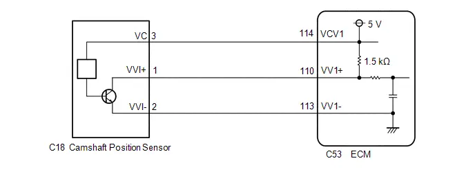
CAUTION / NOTICE / HINT
NOTICE:
-
Toyota Prius Vehicle Control History may be stored in the hybrid vehicle control ECU if the engine is malfunctioning. Certain vehicle condition information is recorded when Vehicle Control History is stored. Reading the vehicle conditions recorded in both the freeze frame data and Vehicle Control History can be useful for troubleshooting.
Click here

(Select Powertrain in Health Check and then check the time stamp data.)
-
If any "Engine Malfunction" Toyota Prius Vehicle Control History item has been stored in the hybrid vehicle control ECU, make sure to clear it. However, as all Vehicle Control History items are cleared simultaneously, if any Vehicle Control History items other than "Engine Malfunction" are stored, make sure to perform any troubleshooting for them before clearing Toyota Prius Vehicle Control History.
Click here

HINT:
If no problem is found through this diagnostic troubleshooting procedure, there may be a mechanical problem with the engine.
PROCEDURE
| 1. | CLEAR DTC |
Pre-procedure1
(a) None
Procedure1
(b) Clear the DTCs.
Powertrain > Engine > Clear DTCsPost-procedure1
(c) Turn the ignition switch off and wait for at least 30 seconds.
|

| 2. | CHECK DTC OUTPUT (DTC P034011 OR P034015) |
HINT:
Make sure that the connector is properly connected. If it is not, securely connect it and check for DTCs again.
Pre-procedure1
(a) Disconnect the camshaft position sensor connector.
(b) Drive the Toyota Prius vehicle in accordance with the driving pattern described in Confirmation Driving Pattern.
Procedure1
(c) Read the DTCs.
Powertrain > Engine > Trouble CodesHINT:
When the ECM, wire harnesses and connectors are normal, DTC P034015 will be stored when the connector of the sensor is disconnected.
| Result | Proceed to |
|---|---|
| P034015 is output | A |
| P034011 is output | B |
Post-procedure1
(d) None
| A |

| REPLACE CAMSHAFT POSITION SENSOR |
|

| 3. | CHECK HARNESS AND CONNECTOR (CAMSHAFT POSITION SENSOR - ECM) |
Pre-procedure1
(a) Disconnect the camshaft position sensor connector.
(b) Disconnect the ECM connector.
Procedure1
(c) Measure the resistance according to the value(s) in the table below.
Standard Resistance:
 Click Location & Routing(C18,C53) Click Connector(C18) Click Connector(C53)
 | Tester Connection | Condition | Specified Condition | Result |
|---|---|---|---|
| C18-1 (VVI ) or C53-110 (VV1 ) - Body ground and other terminals | Always | 10 kΩ or higher | kΩ |
| C18-2 (VVI-) or C53-113 (VV1-) - Body ground and other terminals | Always | 10 kΩ or higher | kΩ |
Post-procedure1
(d) None
| OK |

| REPLACE ECM |
| NG |

| REPAIR OR REPLACE HARNESS OR CONNECTOR |
Camshaft Position Sensor "A" Bank 1 or Single Sensor Circuit Short to Battery or Open (P034015)
DESCRIPTION
Refer to DTC P034011.
Click here

| DTC No. | Detection Item | DTC Detection Condition | Trouble Area | MIL | DTC Output from | Priority | Note |
|---|---|---|---|---|---|---|---|
| P034015 | Camshaft Position Sensor "A" Bank 1 or Single Sensor Circuit Short to Battery or Open | Diagnosis condition:
Abnormal condition:
Malfunction time:
Trip logic:
Detection conditions:
Sensors/components used for detection (Main):
Sensors/components used for detection (Related):
|
| Comes on | Engine | A | SAE Code: P0343 |
-
Reference: Inspection using an oscilloscope.
Click here

MONITOR DESCRIPTION
2 seconds or more after the ignition switch has been turned ON, if the output voltage of the camshaft position sensor is higher than 4.7 V for 4 seconds or more, the ECM determines that the camshaft position sensor circuit is malfunctioning and illuminates the MIL and stores a DTC.
MONITOR STRATEGY
| Required Sensors/Components (Main) | Camshaft position sensor |
| Required Sensors/Components (Related) | Crankshaft position sensor |
| Frequency of Operation | Continuous |
CONFIRMATION DRIVING PATTERN
Refer to DTC P034011.
Click here

WIRING DIAGRAM
Refer to DTC P034011.
Click here

CAUTION / NOTICE / HINT
NOTICE:
-
Toyota Prius Vehicle Control History may be stored in the hybrid vehicle control ECU if the engine is malfunctioning. Certain vehicle condition information is recorded when Vehicle Control History is stored. Reading the vehicle conditions recorded in both the freeze frame data and Vehicle Control History can be useful for troubleshooting.
Click here

(Select Powertrain in Health Check and then check the time stamp data.)
-
If any "Engine Malfunction" Toyota Prius Vehicle Control History item has been stored in the hybrid vehicle control ECU, make sure to clear it. However, as all Vehicle Control History items are cleared simultaneously, if any Vehicle Control History items other than "Engine Malfunction" are stored, make sure to perform any troubleshooting for them before clearing Toyota Prius Vehicle Control History.
Click here

HINT:
If no problem is found through this diagnostic troubleshooting procedure, there may be a mechanical problem with the engine.
PROCEDURE
| 1. | CHECK TERMINAL VOLTAGE (CAMSHAFT POSITION SENSOR) |
HINT:
Make sure that the connector is properly connected. If it is not, securely connect it and check for DTCs again.
Pre-procedure1
(a) Disconnect the camshaft position sensor connector.
(b) Turn the ignition switch ON.
Procedure1
(c) Measure the voltage according to the value(s) in the table below.
Standard Voltage:
 Click Location & Routing(C18) Click Connector(C18)
 | Tester Connection | Condition | Specified Condition |
|---|---|---|
| C18-3 (VC) - Body ground | Ignition switch ON | 4.5 to 5.5 V |
| Result | Proceed to |
|---|---|
| Higher than 5.5 V | A |
| 4.5 to 5.5 V | B |
| Below 4.5 V | C |
Post-procedure1
(d) None
| B |

| GO TO STEP 3 |
| C |

| GO TO STEP 10 |
|

| 2. | CHECK HARNESS AND CONNECTOR (CAMSHAFT POSITION SENSOR - ECM) |
Pre-procedure1
(a) Disconnect the camshaft position sensor connector.
(b) Disconnect the ECM connector.
Procedure1
(c) Measure the resistance according to the value(s) in the table below.
Standard Resistance:
 Click Location & Routing(C18,C53) Click Connector(C18) Click Connector(C53)
 | Tester Connection | Condition | Specified Condition | Result |
|---|---|---|---|
| C18-3 (VC) or C53-114 (VCV1) - Other terminals | Always | 10 kΩ or higher | kΩ |
Post-procedure1
(d) None
| OK |

| REPLACE ECM |
| NG |

| REPAIR OR REPLACE HARNESS OR CONNECTOR |
| 3. | CHECK TERMINAL VOLTAGE (CAMSHAFT POSITION SENSOR) |
Pre-procedure1
(a) Disconnect the camshaft position sensor connector.
(b) Turn the ignition switch ON.
Procedure1
(c) Measure the voltage according to the value(s) in the table below.
Standard Voltage:
 Click Location & Routing(C18) Click Connector(C18)
 | Tester Connection | Condition | Specified Condition |
|---|---|---|
| C18-1 (VVI ) - Body ground | Ignition switch ON | 3.0 to 5.0 V |
| Result | Proceed to |
|---|---|
| Higher than 5.0 V | A |
| 3.0 to 5.0 V | B |
| Below 3.0 V | C |
Post-procedure1
(d) None
| B |

| GO TO STEP 5 |
| C |

| GO TO STEP 9 |
|

| 4. | CHECK HARNESS AND CONNECTOR (CAMSHAFT POSITION SENSOR - ECM) |
Pre-procedure1
(a) Disconnect the camshaft position sensor connector.
(b) Disconnect the ECM connector.
Procedure1
(c) Measure the resistance according to the value(s) in the table below.
Standard Resistance:
 Click Location & Routing(C18,C53) Click Connector(C18) Click Connector(C53)
 | Tester Connection | Condition | Specified Condition | Result |
|---|---|---|---|
| C18-1 (VVI ) or C53-110 (VV1 ) - Other terminals | Always | 10 kΩ or higher | kΩ |
Post-procedure1
(d) None
| OK |

| REPLACE ECM |
| NG |

| REPAIR OR REPLACE HARNESS OR CONNECTOR |
| 5. | CHECK HARNESS AND CONNECTOR (CAMSHAFT POSITION SENSOR - BODY GROUND) |
Pre-procedure1
(a) Disconnect the camshaft position sensor connector.
Procedure1
(b) Measure the resistance according to the value(s) in the table below.
Standard Resistance:
 Click Location & Routing(C18) Click Connector(C18)
 | Tester Connection | Condition | Specified Condition | Result |
|---|---|---|---|
| C18-2 (VVI-) - Body ground | Always | Below 1 Ω | Ω |
Post-procedure1
(c) None
| NG |

| GO TO STEP 8 |
|

| 6. | CHECK INTERNAL RESISTANCE (ECM) |
Pre-procedure1
(a) Turn the ignition switch off.
(b) Disconnect the camshaft position sensor connector.
Procedure1
(c) Measure the resistance according to the value(s) in the table below.
Standard Resistance:
 Click Location & Routing(C18) Click Connector(C18)
 | Tester Connection | Condition | Specified Condition | Result |
|---|---|---|---|
| C18-3 (VC) - C18-1 (VVI ) | Ignition switch off | 1.425 to 1.575 kΩ | kΩ |
HINT:
As voltage is still supplied to the ECM after the ignition switch is turned off, this check cannot be performed correctly during the shut-down process.
Post-procedure1
(d) None
| OK |

| REPLACE CAMSHAFT POSITION SENSOR |
|

| 7. | CHECK HARNESS AND CONNECTOR (CAMSHAFT POSITION SENSOR - ECM) |
Pre-procedure1
(a) Disconnect the camshaft position sensor connector.
(b) Disconnect the ECM connector.
Procedure1
(c) Measure the resistance according to the value(s) in the table below.
Standard Resistance:
 Click Location & Routing(C18,C53) Click Connector(C18) Click Connector(C53)
 | Tester Connection | Condition | Specified Condition | Result |
|---|---|---|---|
| C18-3 (VC) - C18-1 (VVI ) or C53-114 (VCV1) - C53-110 (VV1 ) | Always | 10 kΩ or higher | kΩ |
Post-procedure1
(d) None
| OK |

| REPLACE ECM |
| NG |

| REPAIR OR REPLACE HARNESS OR CONNECTOR |
| 8. | CHECK HARNESS AND CONNECTOR (CAMSHAFT POSITION SENSOR - ECM) |
Pre-procedure1
(a) Disconnect the camshaft position sensor connector.
(b) Disconnect the ECM connector.
Procedure1
(c) Measure the resistance according to the value(s) in the table below.
Standard Resistance:
 Click Location & Routing(C18,C53) Click Connector(C18) Click Connector(C53)
 | Tester Connection | Condition | Specified Condition | Result |
|---|---|---|---|
| C18-2 (VVI-) - C53-113 (VV1-) | Always | Below 1 Ω | Ω |
Post-procedure1
(d) None
| OK |

| REPLACE ECM |
| NG |

| REPAIR OR REPLACE HARNESS OR CONNECTOR |
| 9. | CHECK HARNESS AND CONNECTOR (CAMSHAFT POSITION SENSOR - ECM) |
Pre-procedure1
(a) Disconnect the camshaft position sensor connector.
(b) Disconnect the ECM connector.
Procedure1
(c) Measure the resistance according to the value(s) in the table below.
Standard Resistance:
 Click Location & Routing(C18,C53) Click Connector(C18) Click Connector(C53)
 | Tester Connection | Condition | Specified Condition | Result |
|---|---|---|---|
| C18-1 (VVI ) - C53-110 (VV1 ) | Always | Below 1 Ω | Ω |
Post-procedure1
(d) None
| OK |

| REPLACE ECM |
| NG |

| REPAIR OR REPLACE HARNESS OR CONNECTOR |
| 10. | CHECK HARNESS AND CONNECTOR (CAMSHAFT POSITION SENSOR - ECM) |
Pre-procedure1
(a) Disconnect the camshaft position sensor connector.
(b) Disconnect the ECM connector.
Procedure1
(c) Measure the resistance according to the value(s) in the table below.
Standard Resistance:
 Click Location & Routing(C18,C53) Click Connector(C18) Click Connector(C53)
 | Tester Connection | Condition | Specified Condition | Result |
|---|---|---|---|
| C18-3 (VC) - C53-114 (VCV1) | Always | Below 1 Ω | Ω |
Post-procedure1
(d) None
| OK |

| REPLACE ECM |
| NG |

| REPAIR OR REPLACE HARNESS OR CONNECTOR |
Camshaft Position Sensor "A" Bank 1 or Single Sensor Signal Stuck in Range (P03402A)
DESCRIPTION
Refer to DTC P034011.
Click here

| DTC No. | Detection Item | DTC Detection Condition | Trouble Area | MIL | DTC Output from | Priority | Note |
|---|---|---|---|---|---|---|---|
| P03402A | Camshaft Position Sensor "A" Bank 1 or Single Sensor Signal Stuck in Range | Diagnosis condition:
Abnormal condition:
Malfunction time:
Trip logic:
Detection conditions:
Sensors/components used for detection (Main):
Sensors/components used for detection (Related):
|
| Comes on | Engine | A | SAE Code: P0340 |
-
Reference: Inspection using an oscilloscope.
Click here

MONITOR DESCRIPTION
When the engine is cranking and no camshaft position sensor signal is received for 2 times, the ECM determines that the camshaft position sensor circuit is malfunctioning and illuminates the MIL and stores a DTC.
MONITOR STRATEGY
| Required Sensors/Components (Main) | Camshaft position sensor |
| Required Sensors/Components (Related) | Crankshaft position sensor |
| Frequency of Operation | Continuous |
CONFIRMATION DRIVING PATTERN
- Clear the DTCs (even if no DTCs are stored, perform the clear DTC procedure).
- Turn the ignition switch off and wait for at least 30 seconds.
- Turn the ignition switch ON.
-
Put the engine in Inspection Mode (Maintenance Mode).
Click here

- Start the engine.
- Idle the engine for 10 seconds or more.
- Enter the following menus: Powertrain / Engine / Trouble Codes.
-
Read the pending DTCs.
HINT:
- If a pending DTC is output, the system is malfunctioning.
- If a pending DTC is not output, perform the following procedure.
- Enter the following menus: Powertrain / Engine / Utility / All Readiness.
- Proceed to the next screen and enter the DTC to be checked.
-
Check the DTC judgment result.
HINT:
- If the judgment result is NORMAL, the system is normal.
- If the judgment result is ABNORMAL, the system is malfunctioning.
- If the judgment result is INCOMPLETE, perform the Confirmation Driving Pattern and check the DTC judgment result again.
WIRING DIAGRAM
Refer to DTC P034011.
Click here

CAUTION / NOTICE / HINT
NOTICE:
-
Toyota Prius Vehicle Control History may be stored in the hybrid vehicle control ECU if the engine is malfunctioning. Certain vehicle condition information is recorded when Vehicle Control History is stored. Reading the vehicle conditions recorded in both the freeze frame data and Vehicle Control History can be useful for troubleshooting.
Click here

(Select Powertrain in Health Check and then check the time stamp data.)
-
If any "Engine Malfunction" Toyota Prius Vehicle Control History item has been stored in the hybrid vehicle control ECU, make sure to clear it. However, as all Vehicle Control History items are cleared simultaneously, if any Vehicle Control History items other than "Engine Malfunction" are stored, make sure to perform any troubleshooting for them before clearing Toyota Prius Vehicle Control History.
Click here

HINT:
If no problem is found through this diagnostic troubleshooting procedure, there may be a mechanical problem with the engine.
PROCEDURE
| 1. | CHECK TERMINAL VOLTAGE AND INTERNAL RESISTANCE (CAMSHAFT POSITION SENSOR AND ECM) |
HINT:
Make sure that the connector is properly connected. If it is not, securely connect it and check for DTCs again.
Pre-procedure1
(a) Disconnect the camshaft position sensor connector.
(b) Turn the ignition switch ON.
Procedure1
(c) Measure the voltage according to the value(s) in the table below.
Standard Voltage:
 Click Location & Routing(C18) Click Connector(C18)
 | Tester Connection | Condition | Specified Condition | Result |
|---|---|---|---|
| C18-3 (VC) - Body ground | Ignition switch ON | 4.5 to 5.5 V | V |
| C18-1 (VVI ) - Body ground | Ignition switch ON | 3.0 to 5.0 V | V |
Post-procedure1
(d) Turn the ignition switch off.
Pre-procedure2
(e) None
Procedure2
(f) Measure the resistance according to the value(s) in the table below.
Standard Resistance:
 Click Location & Routing(C18) Click Connector(C18)
 | Tester Connection | Condition | Specified Condition | Result |
|---|---|---|---|
| C18-2 (VVI-) - Body ground | Ignitionr switch off | Below 1 Ω | Ω |
Post-procedure2
(g) None
| NG |

| GO TO STEP 4 |
|

| 2. | INSPECT CAMSHAFT POSITION SENSOR |
Pre-procedure1
(a) Remove the camshaft position sensor.
HINT:
Click here

Procedure1
(b) Confirm that there is no oil on the connecting parts of the camshaft position sensor connector.
OK:
There is no oil on the connecting parts of the camshaft position sensor connector.
Post-procedure1
(c) None
| NG |

| REPLACE CAMSHAFT POSITION SENSOR |
|

| 3. | INSPECT CAMSHAFT POSITION SENSOR |
Pre-procedure1
| (a) Disconnect the camshaft position sensor connector. |
|
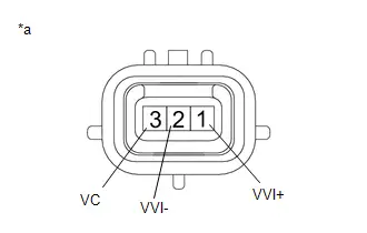
Procedure1
(b) Measure the resistance according to the value(s) in the table below.
Standard Resistance:
| Tester Connection | Condition | Specified Condition | Result |
|---|---|---|---|
| 3 (VC) - 1 (VVI ) | Always | 10 kΩ or higher | kΩ |
| 3 (VC) - 2 (VVI-) | Always | 10 kΩ or higher | kΩ |
| 1 (VVI ) - 2 (VVI-) | Always | 10 kΩ or higher | kΩ |
Post-procedure1
(c) None
| OK |

| REPLACE ECM |
| NG |

| REPLACE CAMSHAFT POSITION SENSOR |
| 4. | CHECK HARNESS AND CONNECTOR (CAMSHAFT POSITION SENSOR - ECM) |
Pre-procedure1
(a) Disconnect the camshaft position sensor connector.
(b) Disconnect the ECM connector.
Procedure1
(c) Measure the resistance according to the value(s) in the table below.
Standard Resistance:
 Click Location & Routing(C18,C53) Click Connector(C18) Click Connector(C53)
 | Tester Connection | Condition | Specified Condition | Result |
|---|---|---|---|
| C18-3 (VC) - C53-114 (VCV1) | Always | Below 1 Ω | Ω |
| C18-1 (VVI ) - C53-110 (VV1 ) | Always | Below 1 Ω | Ω |
| C18-2 (VVI-) - C53-113 (VV1-) | Always | Below 1 Ω | Ω |
| C18-3 (VC) or C53-114 (VCV1) - Body ground and other terminals | Always | 10 kΩ or higher | kΩ |
| C18-1 (VVI ) or C53-110 (VV1 ) - Body ground and other terminals | Always | 10 kΩ or higher | kΩ |
| C18-2 (VVI-) or C53-113 (VV1-) - Body ground and other terminals | Always | 10 kΩ or higher | kΩ |
Post-procedure1
(d) None
| OK |

| REPLACE ECM |
| NG |

| REPAIR OR REPLACE HARNESS OR CONNECTOR |
Camshaft Position Sensor "A" Bank 1 or Single Sensor No Signal (P034031)
DESCRIPTION
Refer to DTC P034011.
Click here

| DTC No. | Detection Item | DTC Detection Condition | Trouble Area | MIL | DTC Output from | Priority | Note |
|---|---|---|---|---|---|---|---|
| P034031 | Camshaft Position Sensor "A" Bank 1 or Single Sensor No Signal | Diagnosis condition:
Abnormal condition:
Malfunction time:
Trip logic:
Detection conditions:
Sensors/components used for detection (Main):
Sensors/components used for detection (Related):
|
| Comes on | Engine | B | SAE Code: P0340 |
-
Reference: Inspection using an oscilloscope.
Click here

MONITOR DESCRIPTION
When the engine is running and no camshaft position sensor signal is received for 5 seconds or more, the ECM determines that the camshaft position sensor circuit is malfunctioning and illuminates the MIL and stores a DTC.
MONITOR STRATEGY
| Required Sensors/Components (Main) | Camshaft position sensor |
| Required Sensors/Components (Related) | Crankshaft position sensor |
| Frequency of Operation | Continuous |
CONFIRMATION DRIVING PATTERN
Refer to DTC P03402A.
Click here

WIRING DIAGRAM
Refer to DTC P034011.
Click here

CAUTION / NOTICE / HINT
NOTICE:
-
Toyota Prius Vehicle Control History may be stored in the hybrid vehicle control ECU if the engine is malfunctioning. Certain vehicle condition information is recorded when Vehicle Control History is stored. Reading the vehicle conditions recorded in both the freeze frame data and Vehicle Control History can be useful for troubleshooting.
Click here

(Select Powertrain in Health Check and then check the time stamp data.)
-
If any "Engine Malfunction" Toyota Prius Vehicle Control History item has been stored in the hybrid vehicle control ECU, make sure to clear it. However, as all Vehicle Control History items are cleared simultaneously, if any Vehicle Control History items other than "Engine Malfunction" are stored, make sure to perform any troubleshooting for them before clearing Toyota Prius Vehicle Control History.
Click here

HINT:
If no problem is found through this diagnostic troubleshooting procedure, there may be a mechanical problem with the engine.
PROCEDURE
| 1. | CHECK DTC OUTPUT (DTC P034031 AND P034011 OR P034015) |
(a) Read the DTCs.
Powertrain > Engine > Trouble Codes| Result | Proceed to |
|---|---|
| P034031 and P034011 are output | A |
| P034031 and P034015 are output | B |
| P034031 is output | C |
HINT:
If DTC P034011 or P034015 is output, perform troubleshooting for it first.
| A |

| GO TO DTC CHART |
| B |

| GO TO DTC CHART |
|

| 2. | CHECK TERMINAL VOLTAGE AND INTERNAL RESISTANCE (CAMSHAFT POSITION SENSOR AND ECM) |
HINT:
Make sure that the connector is properly connected. If it is not, securely connect it and check for DTCs again.
Pre-procedure1
(a) Disconnect the camshaft position sensor connector.
(b) Turn the ignition switch ON.
Procedure1
(c) Measure the voltage according to the value(s) in the table below.
Standard Voltage:
 Click Location & Routing(C18) Click Connector(C18)
 | Tester Connection | Condition | Specified Condition | Result |
|---|---|---|---|
| C18-3 (VC) - Body ground | Ignition switch ON | 4.5 to 5.5 V | V |
| C18-1 (VVI ) - Body ground | Ignition switch ON | 3.0 to 5.0 V | V |
Post-procedure1
(d) Turn the ignition switch off.
Pre-procedure2
(e) None
Procedure2
(f) Measure the resistance according to the value(s) in the table below.
Standard Resistance:
 Click Location & Routing(C18) Click Connector(C18)
 | Tester Connection | Condition | Specified Condition | Result |
|---|---|---|---|
| C18-2 (VVI-) - Body ground | Ignition switch off | Below 1 Ω | Ω |
Post-procedure2
(g) None
| NG |

| GO TO STEP 5 |
|

| 3. | INSPECT CAMSHAFT POSITION SENSOR |
Pre-procedure1
(a) Remove the camshaft position sensor.
HINT:
Click here

Procedure1
(b) Confirm that there is no oil on the connecting parts of the camshaft position sensor connector.
OK:
There is no oil on the connecting parts of the camshaft position sensor connector.
Post-procedure1
(c) None
| NG |

| REPLACE CAMSHAFT POSITION SENSOR |
|

| 4. | INSPECT CAMSHAFT POSITION SENSOR |
Pre-procedure1
| (a) Disconnect the camshaft position sensor connector. |
|

Procedure1
(b) Measure the resistance according to the value(s) in the table below.
Standard Resistance:
| Tester Connection | Condition | Specified Condition | Result |
|---|---|---|---|
| 3 (VC) - 1 (VVI ) | Always | 10 kΩ or higher | kΩ |
| 3 (VC) - 2 (VVI-) | Always | 10 kΩ or higher | kΩ |
| 1 (VVI ) - 2 (VVI-) | Always | 10 kΩ or higher | kΩ |
Post-procedure1
(c) None
| OK |

| REPLACE ECM |
| NG |

| REPLACE CAMSHAFT POSITION SENSOR |
| 5. | CHECK HARNESS AND CONNECTOR (CAMSHAFT POSITION SENSOR - ECM) |
Pre-procedure1
(a) Disconnect the camshaft position sensor connector.
(b) Disconnect the ECM connector.
Procedure1
(c) Measure the resistance according to the value(s) in the table below.
Standard Resistance:
 Click Location & Routing(C18,C53) Click Connector(C18) Click Connector(C53)
 | Tester Connection | Condition | Specified Condition | Result |
|---|---|---|---|
| C18-3 (VC) - C53-114 (VCV1) | Always | Below 1 Ω | Ω |
| C18-1 (VVI ) - C53-110 (VV1 ) | Always | Below 1 Ω | Ω |
| C18-2 (VVI-) - C53-113 (VV1-) | Always | Below 1 Ω | Ω |
| C18-3 (VC) or C53-114 (VCV1) - Body ground and other terminals | Always | 10 kΩ or higher | kΩ |
| C18-1 (VVI ) or C53-110 (VV1 ) - Body ground and other terminals | Always | 10 kΩ or higher | kΩ |
| C18-2 (VVI-) or C53-113 (VV1-) - Body ground and other terminals | Always | 10 kΩ or higher | kΩ |
Post-procedure1
(d) None
| OK |

| REPLACE ECM |
| NG |

| REPAIR OR REPLACE HARNESS OR CONNECTOR |
Exhaust Gas Recirculation "A" Low / Insufficient Flow (P04019C)
DESCRIPTION
Based on the driving conditions, the ECM regulates the volume of exhaust gas that is recirculated to each engine cylinder in order to lower the combustion temperature and reduce NOx emissions. The ECM monitors signals such as engine speed, engine coolant temperature, electric load, and Toyota Prius vehicle speed. When the EGR permission conditions are met, the ECM controls the opening of the EGR valve linearly through signals to the EGR step motor.
| DTC No. | Detection Item | DTC Detection Condition | Trouble Area | MIL | DTC Output from | Priority | Note |
|---|---|---|---|---|---|---|---|
| P04019C | Exhaust Gas Recirculation "A" Low / Insufficient Flow | Change in intake manifold pressure is small when the EGR valve opened and closed during fuel cut operation (2 trip detection logic). |
| Comes on | Engine | B | SAE Code: P0401 |
MONITOR DESCRIPTION
The ECM monitors the pressure inside the intake manifold while opening and closing the EGR valve during fuel cut operation. If there is no change in the manifold absolute pressure sensor value, the ECM interprets this as a malfunction of the EGR valve assembly, illuminates the MIL and stores this DTC.
MONITOR STRATEGY
| Required Sensors/Components (Main) | EGR valve assembly Manifold absolute pressure sensor |
| Required Sensors/Components (Related) | Engine coolant temperature sensor |
| Frequency of Operation | Once per driving cycle |
TYPICAL ENABLING CONDITIONS
| Engine speed | 950 to 1600 rpm |
| Toyota Prius Vehicle speed | 32 km/h (20 mph) or more |
| Intake air temperature | -10°C (14°F) or higher |
TYPICAL MALFUNCTION THRESHOLDS
| Manifold pressure change | Less than 1.72 kPa [0.25 psi] |
| At engine speed | 1050 rpm |
CONFIRMATION DRIVING PATTERN
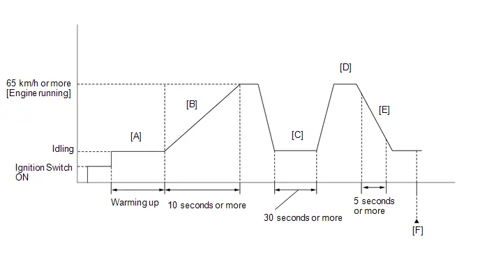
- Clear the DTCs (even if no DTCs are stored, perform the clear DTC procedure).
- Turn the ignition switch off and wait for at least 30 seconds.
- Turn the ignition switch ON.
-
Put the engine in Inspection Mode (Maintenance Mode).
Click here

- Start the engine and warm it up until the engine coolant temperature is 75°C (167°F) or higher [A].
-
With the engine running, accelerate the Toyota Prius vehicle to 65 km/h (40 mph) or more by depressing the accelerator pedal for at least 10 seconds or more [B].
CAUTION:
When performing the confirmation driving pattern, obey all speed limits and traffic laws.
HINT:
When accelerating the vehicle, depress the accelerator pedal more than normal to start the engine.
- Idle the engine for 30 seconds or more [C].
-
With brake (B) selected and the engine running, accelerate the Toyota Prius vehicle to 65 km/h (40 mph) or more [D].
CAUTION:
When performing the confirmation driving pattern, obey all speed limits and traffic laws.
HINT:
If the engine stops, further depress the accelerator pedal to restart the engine.
- Perform the fuel cut operation for 5 seconds or more, with the accelerator pedal fully released [E].
- Enter the following menus: Powertrain / Engine / Trouble Codes [F].
-
Read the pending DTCs.
HINT:
- If a pending DTC is output, the system is malfunctioning.
- If a pending DTC is not output, perform the following procedure.
- Enter the following menus: Powertrain / Engine / Utility / All Readiness.
- Input the DTC P04019C.
-
Check the DTC judgment result.
HINT:
- If the judgment result is NORMAL, the system is normal.
- If the judgment result is ABNORMAL, the system is malfunctioning.
- If the DTC judgment result is INCOMPLETE, perform steps [D] and [E].
WIRING DIAGRAM
Refer to the DTC P040314.
Click here

CAUTION / NOTICE / HINT
NOTICE:
-
Toyota Prius Vehicle Control History may be stored in the hybrid vehicle control ECU assembly if the engine is malfunctioning. Certain vehicle condition information is recorded when Vehicle Control History is stored. Reading the vehicle conditions recorded in both the freeze frame data and Vehicle Control History can be useful for troubleshooting.
Click here

(Select Powertrain in Health Check and then check the time stamp data.)
-
If any "Engine Malfunction" Toyota Prius Vehicle Control History item has been stored in the hybrid vehicle control ECU assembly, make sure to clear it. However, as all Vehicle Control History items are cleared simultaneously, if any Vehicle Control History items other than "Engine Malfunction" are stored, make sure to perform any troubleshooting for them before clearing Toyota Prius Vehicle Control History.
Click here

HINT:
- By using the Control the EGR Step Position Active Test, the operation of the EGR valve can be checked.
-
If the EGR valve is normal and is opened using the Active Test, the Data List value changes as follows.
Data List Item
Change in Data List when Number of Steps is Increased Using Control the EGR Step Position Active Test
Intake Manifold Absolute Pressure
Pressure rises
PROCEDURE
| 1. | CHECK ANY OTHER DTCS OUTPUT (IN ADDITION TO DTC P04019C) |
(a) Read the DTCs.
Powertrain > Engine > Trouble Codes| Result | Proceed to |
|---|---|
| P04019C and other DTCs are output | A |
| P04019C is output | B |
HINT:
If any DTCs other than P04019C are output, troubleshoot those DTCs first.
| A |

| GO TO DTC CHART |
|

| 2. | READ VALUE USING GTS (INTAKE MANIFOLD ABSOLUTE PRESSURE) |
Pre-procedure1
(a) None
Procedure1
(b) Read the value of Intake Manifold Absolute Pressure.
Powertrain > Engine > Data List| Tester Display |
|---|
| Intake Manifold Absolute Pressure |
| Result | Proceed to |
|---|---|
| The value of Intake Manifold Absolute Pressure is between 80 and 110 kPa(abs) | A |
| None of the above conditions are met | B |
HINT:
80 to 110 kPa(abs) = 11.6 to 15.95 psi(abs)
Post-procedure1
(c) None
| B |

| REPLACE MANIFOLD ABSOLUTE PRESSURE SENSOR |
|

| 3. | PERFORM ACTIVE TEST USING GTS (CONTROL THE EGR STEP POSITION) |
Pre-procedure1
(a) Put the engine in Inspection Mode (Maintenance Mode).
Powertrain > Hybrid Control > Utility| Tester Display |
|---|
| Inspection Mode |
(b) Start the engine and warm it up until the engine coolant temperature is 75°C (167°F) or higher.
HINT:
The A/C switch and all accessories should be off.
Procedure1
(c) According to the display on the GTS, compare the values of Data List item Intake Manifold Absolute Pressure before and while performing the Active Test.
Powertrain > Engine > Active Test| Active Test Display |
|---|
| Control the EGR Step Position |
| Data List Display |
|---|
| Intake Manifold Absolute Pressure |
| Engine Independent |
NOTICE:
- Make sure that the value of Data List item Engine Independent is "Operate" while performing the Active Test.
- Do not leave the EGR valve open for 10 seconds or more during the Active Test.
- Be sure to return the EGR valve to step 0 when the Active Test is completed.
- Do not open the EGR valve 30 steps or more during the Active Test.
Standard:
The value of Intake Manifold Absolute Pressure changes according to the EGR valve step set by the Active Test.
| Data List | Control the EGR Step Position (Active Test) | ||
|---|---|---|---|
| Before Active Test (Engine idling) | 0 Steps | 0 to 30 Steps (Engine idling) | |
| Intake Manifold Absolute Pressure | 20 to 40 kPa (2.9 to 5.8 psi) | (EGR valve is fully closed) | Intake Manifold Absolute Pressure value is at least 10 kPa (1.45 psi) higher than when EGR valve is fully closed |
HINT:
- If the value of Data List item Engine Independent is "Not Opr" when the engine is idling, charge control is being performed. Perform the Active Test after charge control is complete ("Operate" is displayed).
- While performing the Active Test, if the increase in the value of Intake Manifold Absolute Pressure is small, the EGR valve assembly may be malfunctioning.
- Even if the EGR valve assembly is malfunctioning, rough idling or an increase in the value of Intake Manifold Absolute Pressure may occur while performing the Active Test. However, the amount that the value of Intake Manifold Absolute Pressure increases will be smaller than normal.
| Result | Proceed to |
|---|---|
| Before performing the Active Test (while the engine is idling), the value of Intake Manifold Absolute Pressure is not between 20 to 40 kPa (2.9 to 5.8 psi). | A |
| When performing the Active Test to change the EGR valve step between 0 (EGR valve fully closed) and 30, the value of Intake Manifold Absolute Pressure changes less than 10 kPa (1.42 psi). | B |
| Other than above | C |
Post-procedure1
(d) None
| B |

| GO TO STEP 6 |
| C |

| GO TO STEP 12 |
|

| 4. | CHECK INTAKE SYSTEM |
(a) Check the intake system for vacuum leaks.
Click here

OK:
No leaks from intake system.
HINT:
Perform "Inspection After Repair" after replacing the intake system.
Click here

| NG |

| REPAIR OR REPLACE INTAKE SYSTEM |
|

| 5. | INSPECT EGR VALVE ASSEMBLY |
Pre-procedure1
(a) Remove the EGR valve assembly.
HINT:
Click here

Procedure1
(b) Check if the EGR valve is stuck open.
OK:
EGR valve is tightly closed.
Post-procedure1
(c) None
| OK |

| REPLACE MANIFOLD ABSOLUTE PRESSURE SENSOR |
| NG |

| REPLACE EGR VALVE ASSEMBLY |
| 6. | REPLACE EGR VALVE ASSEMBLY |
HINT:
Click here

|

| 7. | CLEAR DTC |
Pre-procedure1
(a) None
Procedure1
(b) Clear the DTCs.
Powertrain > Engine > Clear DTCsPost-procedure1
(c) Turn the ignition switch off and wait for at least 30 seconds.
|

| 8. | CHECK WHETHER DTC OUTPUT RECURS (DTC P04019C) |
Pre-procedure1
(a) Drive the Toyota Prius vehicle in accordance with the driving pattern described in Confirmation Driving Pattern.
Procedure1
(b) Read the DTCs.
Powertrain > Engine > Trouble Codes| Result | Proceed to |
|---|---|
| DTCs are not output | A |
| P04019C is output | B |
Post-procedure1
(c) None
| A |

| END |
|

| 9. | REPLACE EGR PIPE WITH COOLER SUB-ASSEMBLY |
HINT:
-
Click here

- If any of the EGR system related pipes (EGR pipe, exhaust manifold, etc.) are cracked, damaged or clogged, replace them as necessary.
-
Perform "Inspection After Repair" after replacing the EGR system.
Click here

|

| 10. | CLEAR DTC |
Pre-procedure1
(a) None
Procedure1
(b) Clear the DTCs.
Powertrain > Engine > Clear DTCsPost-procedure1
(c) Turn the ignition switch off and wait for at least 30 seconds.
|

| 11. | CHECK WHETHER DTC OUTPUT RECURS (DTC P04019C) |
Pre-procedure1
(a) Drive the Toyota Prius vehicle in accordance with the driving pattern described in Confirmation Driving Pattern.
Procedure1
(b) Read the DTCs.
Powertrain > Engine > Trouble CodesOK:
DTCs are not output.
Post-procedure1
(c) None
| NEXT |

| END |
| 12. | CLEAR DTC |
Pre-procedure1
(a) None
Procedure1
(b) Clear the DTCs.
Powertrain > Engine > Clear DTCsPost-procedure1
(c) Turn the ignition switch off and wait for at least 30 seconds.
|

| 13. | CHECK WHETHER DTC OUTPUT RECURS (DTC P04019C) |
Pre-procedure1
(a) Drive the Toyota Prius vehicle in accordance with the driving pattern described in Confirmation Driving Pattern.
Procedure1
(b) Read the DTCs.
Powertrain > Engine > Trouble Codes| Result | Proceed to |
|---|---|
| DTCs are not output | A |
| P04019C is output | B |
Post-procedure1
(c) None
| A |

| END |
| B |

| REPLACE EGR VALVE ASSEMBLY |
Exhaust Gas Recirculation "A" Control Circuit 1 Open (P040314,P140000,P140596,P141004)
DESCRIPTION
Refer to DTC P04019C.
Click here

| DTC No. | Detection Item | DTC Detection Condition | Trouble Area | MIL | DTC Output from | Priority | Note |
|---|---|---|---|---|---|---|---|
| P040314 | Exhaust Gas Recirculation "A" Control Circuit 1 Open | Open or short in EGR1 circuit for 1 second or more (1 trip detection logic). |
| Comes on | Engine | A | SAE Code: P0403 |
| P140000 | Exhaust Gas Recirculation "A" Control Circuit 2 Open | Open or short in EGR2 circuit for 1 second or more (1 trip detection logic). |
| Comes on | Engine | A | SAE Code: P0403 |
| P140596 | Exhaust Gas Recirculation "A" Control Circuit 3 Open | Open or short in EGR3 circuit for 1 second or more (1 trip detection logic). |
| Comes on | Engine | A | SAE Code: P0403 |
| P141004 | Exhaust Gas Recirculation "A" Control Circuit 4 Open | Open or short in EGR4 circuit for 1 second or more (1 trip detection logic). |
| Comes on | Engine | A | SAE Code: P0403 |
MONITOR DESCRIPTION
These DTCs are stored if an open or short in the EGR valve assembly circuit is detected.
Example:
- If the EGR1, EGR2, EGR3 or EGR4 terminal output voltage is excessively low, but the step motor is still operating, the ECM determines that there is a short in the EGR valve assembly circuit, illuminate the MIL and stores a DTC.
- If the EGR1, EGR2, EGR3 or EGR4 terminal output voltage is excessively low, and the step motor is not operating, the ECM determines that there is an open in the EGR valve assembly circuit, illuminate the MIL and stores a DTC.
MONITOR STRATEGY
| Frequency of Operation | Continuous |
CONFIRMATION DRIVING PATTERN
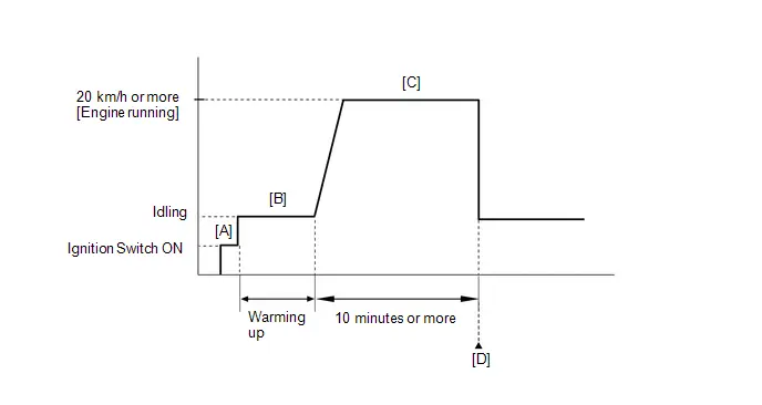
- Clear the DTCs (even if no DTCs are stored, perform the clear DTC procedure).
- Turn the ignition switch off and wait for at least 30 seconds.
- Turn the ignition switch ON [A].
-
Put the engine in Inspection Mode (Maintenance Mode).
Click here

- Start the engine and warm it up [B].
-
With the engine running, drive the Toyota Prius vehicle at 20 km/h (12 mph) or more for 10 minutes or more [C].
CAUTION:
When performing the confirmation driving pattern, obey all speed limits and traffic laws.
HINT:
If the engine stops, further depress the accelerator pedal to restart the engine.
- Enter the following menus: Powertrain / Engine / Trouble Codes [D].
-
Read the pending DTCs.
HINT:
- If a pending DTC is output, the system is malfunctioning.
- If a pending DTC is not output, perform the following procedure.
- Enter the following menus: Powertrain / Engine / Utility / All Readiness.
- Input the DTC: P040314, P140000, P140596 or P141004.
-
Check the DTC judgment result.
HINT:
- If the judgment result is NORMAL, the system is normal.
- If the judgment result is ABNORMAL, the system is malfunctioning.
- If the judgment result is INCOMPLETE, perform the Confirmation Driving Pattern and check the DTC judgment result again.
WIRING DIAGRAM
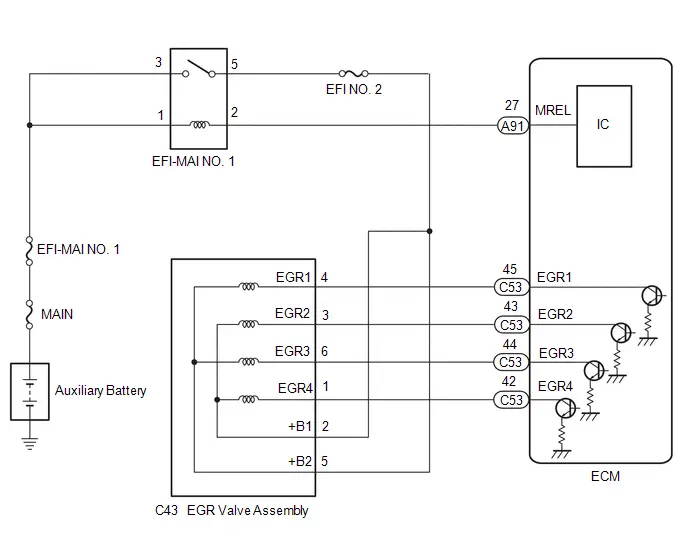
CAUTION / NOTICE / HINT
NOTICE:
- Inspect the fuses for circuits related to this system before performing the following procedure.
-
Toyota Prius Vehicle Control History may be stored in the hybrid vehicle control ECU assembly if the engine is malfunctioning. Certain vehicle condition information is recorded when Vehicle Control History is stored. Reading the vehicle conditions recorded in both the freeze frame data and Vehicle Control History can be useful for troubleshooting.
Click here

(Select Powertrain in Health Check and then check the time stamp data.)
-
If any "Engine Malfunction" Toyota Prius Vehicle Control History item has been stored in the hybrid vehicle control ECU assembly, make sure to clear it. However, as all Vehicle Control History items are cleared simultaneously, if any Vehicle Control History items other than "Engine Malfunction" are stored, make sure to perform any troubleshooting for them before clearing Toyota Prius Vehicle Control History.
Click here

PROCEDURE
| 1. | PERFORM ACTIVE TEST USING GTS (CONTROL THE EGR STEP POSITION) |
Pre-procedure1
(a) Put the engine in Inspection Mode (Maintenance Mode).
Powertrain > Hybrid Control > Utility| Tester Display |
|---|
| Inspection Mode |
(b) Start the engine and warm it up until the engine coolant temperature is 75°C (167°F) or higher.
Powertrain > Engine > Data List| Tester Display |
|---|
| Coolant Temperature |
HINT:
The A/C switch and all accessories should be off.
Procedure1
(c) Confirm that the value of Data List item Engine Independent is "Operate" then check the value of Intake Manifold Absolute Pressure while performing the Active Test.
Powertrain > Engine > Active Test| Active Test Display |
|---|
| Control the EGR Step Position |
| Data List Display |
|---|
| Intake Manifold Absolute Pressure |
| Engine Independent |
NOTICE:
- Do not leave the EGR valve open for 10 seconds or more during the Active Test.
- Be sure to return the EGR valve to step 0 when the Active Test is completed.
- Do not open the EGR valve 30 steps or more during the Active Test.
OK:
The value of Intake Manifold Absolute Pressure changes in response to the EGR step position when the value of Engine Independent is "Operate".
Standard:
| - | Control the EGR Step Position (Active Test) | |
|---|---|---|
| 0 Steps | 0 to 30 Steps | |
| Intake Manifold Absolute Pressure (Data List) | (EGR valve is fully closed) | Intake Manifold Absolute Pressure value is at least 10 kPa (1.45 psi) higher than when EGR valve is fully closed |
HINT:
- If the value of Data List item Engine Independent is "Not Opr" when the engine is idling, charge control is being performed. Perform the Active Test after charge control is complete ("Operate" is displayed).
- While performing the Active Test, if the increase in the value of Intake Manifold Absolute Pressure is small, the EGR valve assembly may be malfunctioning.
- Even if the EGR valve assembly is malfunctioning, rough idling or an increase in the value of Intake Manifold Absolute Pressure may occur while performing the Active Test. However, the amount that the value of Intake Manifold Absolute Pressure increases will be smaller than normal.
Post-procedure1
(d) None
| OK |

| CHECK FOR INTERMITTENT PROBLEMS |
|

| 2. | INSPECT EGR VALVE ASSEMBLY |
Click here

| NG |

| REPLACE EGR VALVE ASSEMBLY |
|

| 3. | CHECK TERMINAL VOLTAGE (POWER SOURCE OF EGR VALVE ASSEMBLY) |
Pre-procedure1
(a) Disconnect the EGR valve assembly connector.
(b) Turn the ignition switch ON.
Procedure1
(c) Measure the voltage according to the value(s) in the table below.
Standard Voltage:
 Click Location & Routing(C43) Click Connector(C43)
 | Tester Connection | Condition | Specified Condition | Result |
|---|---|---|---|
| C43-2 ( B1) - Body ground | Ignition switch ON | 11 to 14 V | V |
| C43-5 ( B2) - Body ground | Ignition switch ON | 11 to 14 V | V |
Post-procedure1
(d) None
| NG |

| GO TO STEP 5 |
|

| 4. | CHECK HARNESS AND CONNECTOR (EGR VALVE ASSEMBLY - ECM) |
Pre-procedure1
(a) Disconnect the EGR valve assembly connector.
(b) Disconnect the ECM connector.
Procedure1
(c) Measure the resistance according to the value(s) in the table below.
Standard Resistance:
 Click Location & Routing(C43,C53) Click Connector(C43) Click Connector(C53)
 | Tester Connection | Condition | Specified Condition | Result |
|---|---|---|---|
| C43-4 (EGR1) - C53-45 (EGR1) | Always | Below 1 Ω | Ω |
| C43-3 (EGR2) - C53-43 (EGR2) | Always | Below 1 Ω | Ω |
| C43-6 (EGR3) - C53-44 (EGR3) | Always | Below 1 Ω | Ω |
| C43-1 (EGR4) - C53-42 (EGR4) | Always | Below 1 Ω | Ω |
| C43-4 (EGR1) or C53-45 (EGR1) - Body ground and other terminals | Always | 10 kΩ or higher | kΩ |
| C43-3 (EGR2) or C53-43 (EGR2) - Body ground and other terminals | Always | 10 kΩ or higher | kΩ |
| C43-6 (EGR3) or C53-44 (EGR3) - Body ground and other terminals | Always | 10 kΩ or higher | kΩ |
| C43-1 (EGR4) or C53-42 (EGR4) - Body ground and other terminals | Always | 10 kΩ or higher | kΩ |
Post-procedure1
(d) None
| OK |

| REPLACE ECM |
| NG |

| REPAIR OR REPLACE HARNESS OR CONNECTOR |
| 5. | INSPECT EFI-MAIN NO. 1 RELAY |
Click here

| NG |

| REPLACE EFI-MAIN NO. 1 RELAY |
|

| 6. | CHECK TERMINAL VOLTAGE (POWER SOURCE OF EFI-MAIN NO. 1 RELAY) |
Pre-procedure1
(a) Remove the EFI-MAIN NO. 1 relay from the No. 1 engine room relay block and No. 1 junction block assembly.
Procedure1
(b) Measure the voltage according to the value(s) in the table below.
Standard Voltage:
| Tester Connection | Condition | Specified Condition | Result |
|---|---|---|---|
| 3 (EFI-MAIN NO. 1 relay) - Body ground | Always | 11 to 14 V | V |
| 1 (EFI-MAIN NO. 1 relay) - Body ground | Always | 11 to 14 V | V |
Post-procedure1
(c) None
| OK |

| REPLACE ECM |
| NG |

| REPAIR OR REPLACE HARNESS OR CONNECTOR (AUXILIARY BATTERY - EFI-MAIN NO. 1 RELAY) |
Catalyst System Efficiency Below Threshold Bank 1 (P042000)
MONITOR DESCRIPTION
The ECM uses sensors mounted in front of and behind the Three-Way Catalytic Converter (TWC) to monitor its efficiency.
The first sensor, the air fuel ratio sensor, sends pre-catalyst information to the ECM. The second sensor, the heated oxygen sensor, sends post-catalyst information to the ECM.
In order to detect any deterioration in the three-way catalytic converter, the ECM calculates the oxygen storage capacity of the three-way catalytic converter. This calculation is based on the output voltage of the heated oxygen sensor while performing active air fuel ratio control.
The oxygen storage capacity value is an indication of the oxygen storage capacity of the three-way catalytic converter. When the Toyota Prius vehicle is being driven with a warm engine, active air fuel ratio control is performed for approximately 30 seconds. When it is performed, the ECM deliberately sets the air fuel ratio to lean or rich levels. If the cycle of the waveform for the heated oxygen sensor is long, the oxygen storage capacity is great. There is a direct correlation between the heated oxygen sensor and the oxygen storage capacity of the three-way catalytic converter.
The ECM uses the oxygen storage capacity value to determine the state of the three-way catalytic converter. If any deterioration has occurred, the ECM will illuminate the MIL and store a DTC.
This system determines the deterioration of the entire catalyst system (including the front and rear catalysts), by using the oxygen storage capacity value of the front catalyst, that is more sensitive than the rear catalyst, as the representative value. Therefore, be sure to replace the front and rear catalysts together when catalyst replacement is necessary.
| DTC No. | Detection Item | DTC Detection Condition | Trouble Area | MIL | DTC Output from | Priority | Note |
|---|---|---|---|---|---|---|---|
| P042000 | Catalyst System Efficiency Below Threshold Bank 1 | The oxygen storage capacity value is less than the standard value under active air fuel ratio control (2 trip detection logic). |
| Comes on | Engine | B | SAE Code: P0420 |
CATALYST LOCATION
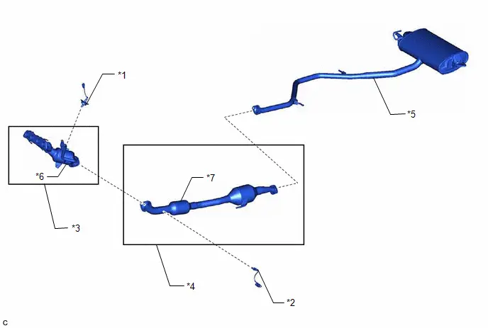
| *1 | Air Fuel Ratio Sensor (Sensor 1) | *2 | Heated Oxygen Sensor (Sensor 2) |
| *3 | Exhaust Manifold | *4 | Front Exhaust Pipe Assembly |
| *5 | Tail Exhaust Pipe Assembly | *6 | TWC: Front Catalyst |
| *7 | TWC: Rear Catalyst | - | - |
NOTICE:
When replacing the exhaust manifold (*3) and the front exhaust pipe assembly (*4) in order to replace the three-way catalytic converter, it is not necessary to replace the air fuel ratio sensor (*1) and the heated oxygen sensor (*2).
MONITOR STRATEGY
| Required Sensors/Components (Main) | Air fuel ratio sensor Heated oxygen sensor |
| Required Sensors/Components (Related) | Intake air temperature sensor Mass air flow meter sub-assembly Crankshaft position sensor Engine coolant temperature sensor |
| Frequency of Operation | Once per driving cycle |
TYPICAL ENABLING CONDITIONS
| Auxiliary battery voltage | 11 V or higher |
| Intake air temperature | -10°C (14°F) or higher |
| Engine coolant temperature | 75°C (167°F) or higher |
| Atmospheric pressure | 76 kPa(abs) [11 psi(abs)] or higher |
| Idling | Off |
| Engine speed | Less than 4000 rpm |
| Air fuel ratio sensor status | Activated |
| Fuel system status | Closed loop |
| Engine load | 10% or higher, and less than 70% |
| All of the following conditions are met | - |
| Mass air flow rate | 7 gm/sec or more, and less than 30 gm/sec |
| Front catalyst temperature (estimated) | 520°C (968°F) or higher, and less than 710°C (1310°F) |
| Rear catalyst temperature (estimated) | 330°C (626°F) or higher, and less than 700°C (1292°F) |
CONFIRMATION DRIVING PATTERN
HINT:
- It is necessary for the response of the heated oxygen sensor to be normal in order to confirm DTC P042000. Therefore, perform the confirmation driving pattern for the heated oxygen sensor monitor before performing the confirmation driving pattern for the catalyst efficiency monitor.
- Performing this confirmation driving pattern will activate the catalyst efficiency monitor. This is very useful for verifying the completion of a repair.
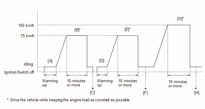
- Clear the DTCs (even if no DTCs are stored, perform the clear DTC procedure).
- Turn the ignition switch off and wait for at least 30 seconds.
- Turn the ignition switch ON.
-
Put the engine in Inspection Mode (Maintenance Mode).
Click here

-
Start the engine and warm it up until the engine coolant temperature is 75°C (167°F) or higher with park (P) selected [A].
HINT:
In order to keep the idle stable, turn the A/C and all other electric loads off and do not perform any shift operations.
-
With the engine running, drive the Toyota Prius vehicle at approximately 75 km/h (47 mph) for 10 minutes or more [B].
CAUTION:
When performing the confirmation driving pattern, obey all speed limits and traffic laws.
HINT:
- Drive the vehicle while keeping the engine load as constant as possible.
- If the engine stops, further depress the accelerator pedal to restart the engine.
- Turn the ignition switch off and wait for at least 30 seconds [C].
- Turn the ignition switch ON.
-
Put the engine in Inspection Mode (Maintenance Mode).
Click here

- Start the engine and warm it up until the engine coolant temperature is 75°C (167°F) or higher [D].
-
With the engine running, drive the Toyota Prius vehicle at approximately 75 km/h (47 mph) for 10 minutes or more [E].
CAUTION:
When performing the confirmation driving pattern, obey all speed limits and traffic laws.
HINT:
- Drive the vehicle while keeping the engine load as constant as possible.
- If the engine stops, further depress the accelerator pedal to restart the engine.
- Enter the following menus: Powertrain / Engine / Trouble Codes [F].
-
Read the pending DTCs.
HINT:
- If a pending DTC is output, the system is malfunctioning.
- If a pending DTC is not output, perform the following procedure.
- Enter the following menus: Powertrain / Engine / Utility / All Readiness.
- Input the DTC: P042000.
-
Check the DTC judgment result.
HINT:
- If the judgment result is NORMAL, the system is normal.
- If the judgment result is ABNORMAL, the system is malfunctioning.
- If the judgment result is INCOMPLETE and no pending DTC is output, perform the following procedure.
-
Drive the Toyota Prius vehicle at 100 km/h (63 mph) for 10 minutes or more [G].
CAUTION:
When performing the confirmation driving pattern, obey all speed limits and traffic laws.
HINT:
- Drive the vehicle while keeping the engine load as constant as possible.
- If the engine stops, further depress the accelerator pedal to restart the engine.
- Enter the following menus: Powertrain / Engine / Trouble Codes [H].
-
Read the pending DTCs.
HINT:
- If a pending DTC is output, the system is malfunctioning.
- If a pending DTC is not output, perform the following procedure.
- Enter the following menus: Powertrain / Engine / Utility / All Readiness.
- Input the DTC: P042000.
-
Check the DTC judgment result.
HINT:
- If the judgment result is NORMAL, the system is normal.
- If the judgment result is ABNORMAL, the system is malfunctioning.
CAUTION / NOTICE / HINT
NOTICE:
-
Toyota Prius Vehicle Control History may be stored in the hybrid vehicle control ECU assembly if the engine is malfunctioning. Certain vehicle condition information is recorded when Vehicle Control History is stored. Reading the vehicle conditions recorded in both the freeze frame data and Vehicle Control History can be useful for troubleshooting.
Click here

(Select Powertrain in Health Check and then check the time stamp data.)
-
If any "Engine Malfunction" Toyota Prius Vehicle Control History item has been stored in the hybrid vehicle control ECU assembly, make sure to clear it. However, as all Vehicle Control History items are cleared simultaneously, if any Vehicle Control History items other than "Engine Malfunction" are stored, make sure to perform any troubleshooting for them before clearing Toyota Prius Vehicle Control History.
Click here

HINT:
- If a malfunction cannot be found when troubleshooting DTC P042000, a lean or rich abnormality may be the cause. Perform troubleshooting by following the inspection procedure for P017100 (System Too Lean) and P017200 (System Too Rich).
- Sensor 1 refers to the sensor closest to the engine assembly.
- Sensor 2 refers to the sensor farthest away from the engine assembly.
PROCEDURE
| 1. | CHECK ANY OTHER DTCS OUTPUT (IN ADDITION TO DTC P042000) |
(a) Read the DTCs.
Powertrain > Engine > Trouble Codes| Result | Proceed to |
|---|---|
| P042000 and other DTCs are output | A |
| P042000 is output | B |
HINT:
If any DTCs other than P042000 are output, troubleshoot those DTCs first.
| A |

| GO TO DTC CHART |
|

| 2. | PERFORM ACTIVE TEST USING GTS (CONTROL THE INJECTION VOLUME FOR A/F SENSOR) |
Pre-procedure1
(a) Put the engine in Inspection Mode (Maintenance Mode).
Powertrain > Hybrid Control > Utility| Tester Display |
|---|
| Inspection Mode |
(b) Start the engine and warm it up until the engine coolant temperature is 75°C (167°F) or higher.
Powertrain > Engine > Data List| Tester Display |
|---|
| Coolant Temperature |
(c) Idle the engine for 5 minutes or more with park (P) selected.
Procedure1
(d) Change the fuel injection volume using the GTS, and monitor the output voltage of the air fuel ratio sensor (A/F (O2) Sensor Current B1S1) and heated oxygen sensor (O2 Sensor Voltage B1S2) displayed on the GTS.
Powertrain > Engine > Active Test| Active Test Display |
|---|
| Control the Injection Volume for A/F Sensor |
| Data List Display |
|---|
| A/F (O2) Sensor Current B1S1 |
| O2 Sensor Voltage B1S2 |
HINT:
- The Active Test "Control the Injection Volume for A/F Sensor" can be used to lower the fuel injection volume by 12.5% or increase the injection volume by 12.5%.
- The air fuel ratio sensor is displayed as A/F (O2) Sensor Current B1S1, and the heated oxygen sensor is displayed as O2 Sensor Voltage B1S2 on the GTS.
- The air fuel ratio sensor has an output delay of a few seconds and the heated oxygen sensor has a maximum output delay of approximately 20 seconds.
- If the sensor output voltage does not change (almost no reaction) while performing the Active Test, the sensor may be malfunctioning.
Standard:
| GTS Display (Sensor) | Injection Volume | Status | Voltage |
|---|---|---|---|
| A/F (O2) Sensor Current B1S1 (Air fuel ratio) | 12.5% | Rich | Below -0.075 mA |
| -12.5% | Lean | Higher than 0.037 mA | |
| O2 Sensor Voltage B1S2 (Heated oxygen) | 12.5% | Rich | Higher than 0.55 V |
| -12.5% | Lean | Below 0.4 V |
| Status A/F (O2) Sensor Current B1S1 | Status O2 Sensor Voltage B1S2 | Actual air fuel ratio, air fuel ratio sensor and heated oxygen sensor condition | Main Suspected Trouble Area | Proceed to |
|---|---|---|---|---|
| Lean/Rich | Lean/Rich | Normal |
| A |
| Lean | Lean/Rich | Air fuel ratio sensor malfunction |
| B |
| Rich | Lean/Rich | Air fuel ratio sensor malfunction |
| |
| Lean/Rich | Lean | Heated oxygen sensor malfunction |
| C |
| Lean/Rich | Rich | Heated oxygen sensor malfunction |
| |
| Lean | Lean | Actual air fuel ratio lean |
| D |
| Rich | Rich | Actual air fuel ratio rich |
|
- Lean: While performing the Active Test "Control the Injection Volume for A/F Sensor", the air fuel ratio sensor output voltage (A/F (O2) Sensor Current B1S1) is consistently higher than 0.037 mA, and the heated oxygen sensor output voltage (O2 Sensor Voltage B1S2) is consistently below 0.4 V.
- Rich: While performing the Active Test "Control the Injection Volume for A/F Sensor", the air fuel ratio sensor output voltage (A/F (O2) Sensor Current B1S1) is consistently below -0.075 mA, and the heated oxygen sensor output voltage (O2 Sensor Voltage B1S2) is consistently higher than 0.55 V.
- Lean/Rich: While performing the Active Test "Control the Injection Volume for A/F Sensor", the output voltage of the fuel ratio sensor (A/F (O2) Sensor Current B1S1) or heated oxygen sensor (O2 Sensor Voltage B1S2) alternates correctly.
Post-procedure1
(e) None
| B |

| GO TO STEP 6 |
| C |

| GO TO STEP 7 |
| D |

| GO TO STEP 9 |
|

| 3. | CHECK FOR EXHAUST GAS LEAK |
(a) Check for exhaust gas leaks.
OK:
No gas leaks in exhaust system.
| NG |

| GO TO STEP 41 |
|

| 4. | PERFORM ACTIVE TEST USING GTS (CONTROL THE EGR STEP POSITION) |
Pre-procedure1
(a) Put the engine in Inspection Mode (Maintenance Mode).
Powertrain > Hybrid Control > Utility| Tester Display |
|---|
| Inspection Mode |
(b) Start the engine and warm it up until the engine coolant temperature is 75°C (167°F) or higher.
HINT:
The A/C switch and all accessories should be off.
Powertrain > Engine > Data List| Tester Display |
|---|
| Coolant Temperature |
Procedure1
(c) Confirm that the value of Data List item Engine Independent is "Operate" then check the value of Intake Manifold Absolute Pressure while performing the Active Test.
Powertrain > Engine > Active Test| Active Test Display |
|---|
| Control the EGR Step Position |
| Data List Display |
|---|
| Intake Manifold Absolute Pressure |
| Engine Independent |
NOTICE:
- Do not leave the EGR valve open for 10 seconds or more during the Active Test.
- Be sure to return the EGR valve to step 0 when the Active Test is completed.
- Do not open the EGR valve 30 steps or more during the Active Test.
OK:
The value of Intake Manifold Absolute Pressure changes in response to the EGR step position when the value of Engine Independent is "Operate".
Standard:
| - | Control the EGR Step Position (Active Test) | |
|---|---|---|
| 0 Steps | 0 to 30 Steps | |
| Intake Manifold Absolute Pressure (Data List) | (EGR valve is fully closed) | Intake Manifold Absolute Pressure value is at least 10 kPa (1.45 psi) higher than when EGR valve is fully closed |
HINT:
- If the value of Data List item Engine Independent is "Not Opr" when the engine is idling, charge control is being performed. Perform the Active Test after charge control is complete ("Operate" is displayed).
- While performing the Active Test, if the increase in the value of Intake Manifold Absolute Pressure is small, the EGR valve assembly may be malfunctioning.
- Even if the EGR valve assembly is malfunctioning, rough idling or an increase in the value of Intake Manifold Absolute Pressure may occur while performing the Active Test. However, the amount that the value of Intake Manifold Absolute Pressure increases will be smaller than normal.
Post-procedure1
(d) None
| OK |

| GO TO STEP 44 |
|

| 5. | INSPECT EGR VALVE ASSEMBLY |
Pre-procedure1
(a) Remove the EGR valve assembly.
HINT:
Click here

Procedure1
(b) Check if the EGR valve is stuck open.
OK:
EGR valve is tightly closed.
Post-procedure1
(c) None
| OK |

| GO TO STEP 44 |
| NG |

| REPLACE EGR VALVE ASSEMBLY |
| 6. | REPLACE AIR FUEL RATIO SENSOR |
HINT:
Click here

| NEXT |

| GO TO STEP 42 |
| 7. | CHECK FOR EXHAUST GAS LEAK |
(a) Check for exhaust gas leaks.
OK:
No gas leaks in exhaust system.
| NG |

| GO TO STEP 41 |
|

| 8. | REPLACE HEATED OXYGEN SENSOR |
HINT:
Click here

| NEXT |

| GO TO STEP 42 |
| 9. | CHECK FOR EXHAUST GAS LEAK |
(a) Check for exhaust gas leaks.
OK:
No gas leaks in exhaust system.
| NG |

| GO TO STEP 41 |
|

| 10. | PERFORM ACTIVE TEST USING GTS (CONTROL THE EGR STEP POSITION) |
Pre-procedure1
(a) Put the engine in Inspection Mode (Maintenance Mode).
Powertrain > Hybrid Control > Utility| Tester Display |
|---|
| Inspection Mode |
(b) Start the engine and warm it up until the engine coolant temperature is 75°C (167°F) or higher.
Powertrain > Engine > Data List| Tester Display |
|---|
| Coolant Temperature |
HINT:
The A/C switch and all accessories should be off.
Procedure1
(c) Confirm that the value of Data List item Engine Independent is "Operate" then check the value of Intake Manifold Absolute Pressure while performing the Active Test.
Powertrain > Engine > Active Test| Active Test Display |
|---|
| Control the EGR Step Position |
| Data List Display |
|---|
| Intake Manifold Absolute Pressure |
| Engine Independent |
NOTICE:
- Do not leave the EGR valve open for 10 seconds or more during the Active Test.
- Be sure to return the EGR valve to step 0 when the Active Test is completed.
- Do not open the EGR valve 30 steps or more during the Active Test.
OK:
The value of Intake Manifold Absolute Pressure changes in response to the EGR step position when the value of Engine Independent is "Operate".
Standard:
| - | Control the EGR Step Position (Active Test) | |
|---|---|---|
| 0 Steps | 0 to 30 Steps | |
| Intake Manifold Absolute Pressure (Data List) | (EGR valve is fully closed) | Intake Manifold Absolute Pressure value is at least 10 kPa (1.45 psi) higher than when EGR valve is fully closed |
HINT:
- If the value of Data List item Engine Independent is "Not Opr" when the engine is idling, charge control is being performed. Perform the Active Test after charge control is complete ("Operate" is displayed).
- While performing the Active Test, if the increase in the value of Intake Manifold Absolute Pressure is small, the EGR valve assembly may be malfunctioning.
- Even if the EGR valve assembly is malfunctioning, rough idling or an increase in the value of Intake Manifold Absolute Pressure may occur while performing the Active Test. However, the amount that the value of Intake Manifold Absolute Pressure increases will be smaller than normal.
Post-procedure1
(d) None
| NG |

| GO TO STEP 40 |
|

| 11. | CHECK PCV HOSE CONNECTIONS |
Click here

| NG |

| REPAIR OR REPLACE PCV HOSE |
|

| 12. | CHECK INTAKE SYSTEM |
Click here

| NG |

| REPAIR OR REPLACE INTAKE SYSTEM |
|

| 13. | PERFORM ACTIVE TEST USING GTS (CONTROL THE INJECTION VOLUME FOR A/F SENSOR) |
Click here

| Status A/F (O2) Sensor Current B1S1 | Status O2 Sensor Voltage B1S2 | Air Fuel Ratio Condition and Air Fuel Ratio Sensor Condition | Suspected Trouble Area | Proceed to |
|---|---|---|---|---|
| Lean/Rich | Lean/Rich | Normal | - | A |
| Lean | Lean | Actual air fuel ratio lean |
| |
| Rich | Rich | Actual air fuel ratio rich |
| |
| Lean | Lean/Rich | Air fuel ratio sensor malfunction |
| B |
| Rich | Lean/Rich | Air fuel ratio sensor malfunction |
|
| B |

| GO TO STEP 22 |
|

| 14. | READ VALUE USING GTS (COOLANT TEMPERATURE) |
Click here

| NG |

| REPLACE ENGINE COOLANT TEMPERATURE SENSOR |
|

| 15. | PERFORM ACTIVE TEST USING GTS (CONTROL THE EGR STEP POSITION) |
Click here

| OK |

| GO TO STEP 17 |
|

| 16. | INSPECT EGR VALVE ASSEMBLY |
Click here

| NG |

| REPLACE EGR VALVE ASSEMBLY |
|

| 17. | READ VALUE USING GTS (MASS AIR FLOW SENSOR) |
Click here

| Result | Proceed to |
|---|---|
| The value of Mass Air Flow Sensor is between 4.5 and 8.5 gm/sec | A |
| None of the above conditions are met | B |
| B |

| GO TO STEP 29 |
|

| 18. | CHECK FUEL PRESSURE |
Click here

| NG |

| REPAIR OR REPLACE FUEL SYSTEM |
|

| 19. | CHECK FOR EXHAUST GAS LEAK |
Click here

HINT:
Perform "Inspection After Repair" after repairing or replacing the exhaust system.
Click here

| NG |

| REPAIR OR REPLACE EXHAUST SYSTEM |
|

| 20. | INSPECT IGNITION SYSTEM |
Click here

HINT:
Perform "Inspection After Repair" after repairing or replacing the ignition system.
Click here

| NG |

| REPAIR OR REPLACE IGNITION SYSTEM |
|

| 21. | INSPECT FUEL INJECTOR ASSEMBLY (INJECTION AND VOLUME) |
Click here

| OK |

| GO TO STEP 29 |
| NG |

| REPLACE FUEL INJECTOR ASSEMBLY |
| 22. | INSPECT AIR FUEL RATIO SENSOR (HEATER RESISTANCE) |
Click here

| NG |

| REPLACE AIR FUEL RATIO SENSOR |
|

| 23. | CHECK TERMINAL VOLTAGE (POWER SOURCE OF AIR FUEL RATIO SENSOR) |
Click here

| NG |

| GO TO STEP 32 |
|

| 24. | CHECK HARNESS AND CONNECTOR (AIR FUEL RATIO SENSOR - ECM) |
Click here

| NG |

| REPAIR OR REPLACE HARNESS OR CONNECTOR |
|

| 25. | REPLACE AIR FUEL RATIO SENSOR |
Click here

|

| 26. | CLEAR DTC |
Click here

|

| 27. | CHECK WHETHER DTC OUTPUT RECURS (DTC P042000) |
Pre-procedure1
(a) Drive the Toyota Prius vehicle in accordance with the driving pattern described in Confirmation Driving Pattern.
Procedure1
(b) Read the DTCs.
Powertrain > Engine > Trouble Codes| Result | Proceed to |
|---|---|
| DTCs are not output | A |
| P042000 is output | B |
Post-procedure1
(c) None
| A |

| END |
|

| 28. | READ VALUE USING GTS (MASS AIR FLOW SENSOR) |
Click here

|

| 29. | CHECK HARNESS AND CONNECTOR (MASS AIR FLOW METER SUB-ASSEMBLY CONNECTOR CONNECTION) |
Click here

|

| 30. | CLEAR DTC |
Click here

|

| 31. | CHECK WHETHER DTC OUTPUT RECURS (DTC P042000) |
Pre-procedure1
(a) Drive the Toyota Prius vehicle in accordance with the driving pattern described in Confirmation Driving Pattern.
Procedure1
(b) Read the DTCs.
Powertrain > Engine > Trouble Codes| Result | Proceed to |
|---|---|
| DTCs are not output | A |
| P042000 is output | B |
Post-procedure1
(c) None
| A |

| END |
| B |

| GO TO STEP 36 |
| 32. | INSPECT EFI-MAIN NO. 2 RELAY |
Click here

| NG |

| REPLACE EFI-MAIN NO. 2 RELAY |
|

| 33. | CHECK TERMINAL VOLTAGE (POWER SOURCE OF EFI-MAIN NO. 2 RELAY) |
Click here

| NG |

| REPAIR OR REPLACE HARNESS OR CONNECTOR (AUXILIARY BATTERY - EFI-MAIN NO. 2 RELAY) |
|

| 34. | CHECK HARNESS AND CONNECTOR (EFI-MAIN NO. 2 RELAY - BODY GROUND) |
Click here

| NG |

| REPAIR OR REPLACE HARNESS OR CONNECTOR |
|

| 35. | CHECK HARNESS AND CONNECTOR (EFI-MAIN NO. 2 RELAY - AIR FUEL RATIO SENSOR) |
Click here

| OK |

| REPAIR OR REPLACE HARNESS OR CONNECTOR (EFI-MAIN NO. 1 RELAY - EFI-MAIN NO. 2 RELAY) |
| NG |

| REPAIR OR REPLACE HARNESS OR CONNECTOR |
| 36. | CHECK HARNESS AND CONNECTOR (MASS AIR FLOW METER SUB-ASSEMBLY - ECM) |
Click here

| NG |

| REPAIR OR REPLACE HARNESS OR CONNECTOR |
|

| 37. | REPLACE MASS AIR FLOW METER SUB-ASSEMBLY |
Click here

|

| 38. | CLEAR DTC |
Click here

|

| 39. | CHECK WHETHER DTC OUTPUT RECURS (DTC P042000) |
Pre-procedure1
(a) Drive the Toyota Prius vehicle in accordance with the driving pattern described in Confirmation Driving Pattern.
Procedure1
(b) Read the DTCs.
Powertrain > Engine > Trouble Codes| Result | Proceed to |
|---|---|
| DTCs are not output | A |
| P042000 is output | B |
Post-procedure1
(c) None
| A |

| END |
| B |

| REPLACE ECM |
| 40. | INSPECT EGR VALVE ASSEMBLY |
Pre-procedure1
(a) Remove the EGR valve assembly.
HINT:
Click here

Procedure1
(b) Check if the EGR valve is stuck open.
OK:
EGR valve is tightly closed.
Post-procedure1
(c) None
| OK |

| REPLACE EGR VALVE ASSEMBLY |
| NG |

| REPLACE EGR VALVE ASSEMBLY |
| 41. | REPAIR OR REPLACE EXHAUST SYSTEM |
(a) Repair or replace exhaust system.
HINT:
Perform "Inspection After Repair" after repairing or replacing the exhaust system.
Click here

|

| 42. | CLEAR DTC |
Pre-procedure1
(a) None
Procedure1
(b) Clear the DTCs.
Powertrain > Engine > Clear DTCsPost-procedure1
(c) Turn the ignition switch off and wait for at least 30 seconds.
|

| 43. | CONFIRM WHETHER MALFUNCTION HAS BEEN SUCCESSFULLY REPAIRED |
Pre-procedure1
(a) Drive the Toyota Prius vehicle in accordance with the driving pattern described in Confirmation Driving Pattern.
Procedure1
(b) Read the DTCs.
Powertrain > Engine > Trouble Codes| Result | Proceed to |
|---|---|
| DTCs are not output | A |
| P042000 is output | B |
Post-procedure1
(c) None
| A |

| END |
|

| 44. | REPLACE EXHAUST MANIFOLD (TWC: FRONT CATALYST) AND FRONT EXHAUST PIPE ASSEMBLY (TWC: REAR CATALYST) |
NOTICE:
When replacing the exhaust manifold and front exhaust pipe assembly in order to replace the three-way catalytic converter, it is not necessary to replace the air fuel ratio sensor and the heated oxygen sensor.
HINT:
Confirm the replacement parts, referring to the illustration in the Catalyst Location.
(a) Replace the exhaust manifold (TWC: Front catalyst).
HINT:
Click here

(b) Replace the front exhaust pipe assembly (TWC: Rear catalyst).
HINT:
Click here

| NEXT |

| END |
Evaporative Emission System Purge Control Valve "A" Circuit Open (P044313)
DESCRIPTION
To reduce hydrocarbon (HC) emissions, evaporated fuel from the fuel tank is routed through a canister to the intake manifold for combustion in the cylinders.
The ECM changes the duty signals to the purge VSV so that the intake amount of evaporated fuel routed to the cylinders is appropriate for the driving conditions (engine load, engine speed, Toyota Prius vehicle speed, etc.) after the engine is warmed up.
| DTC No. | Detection Item | DTC Detection Condition | Trouble Area | MIL | DTC Output from | Priority | Note |
|---|---|---|---|---|---|---|---|
| P044313 | Evaporative Emission System Purge Control Valve "A" Circuit Open | Both of the following conditions are met for 10 seconds or more (1 trip detection logic):
|
| Comes on | Engine | A | SAE Code: P0443 |
CONFIRMATION DRIVING PATTERN
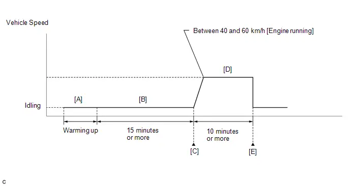
- Clear the DTCs (even if no DTCs are stored, perform the clear DTC procedure).
- Turn the ignition switch off and wait for at least 30 seconds.
- Turn the ignition switch ON.
-
Put the engine in Inspection Mode (Maintenance Mode).
Click here

-
Start the engine and warm it up until the engine coolant temperature is 75°C (167°F) or higher [A].
HINT:
The A/C switch and all accessories should be off.
-
Idle the engine for 15 minutes or more [B].
HINT:
Check the Data List item "EVAP (Purge) VSV". When the value of this item is between 5 and 95%, the judgment will be performed.
- Enter the following menus: Powertrain / Engine / Trouble Codes [C].
-
Read the pending DTCs.
HINT:
- If a pending DTC is output, the system is malfunctioning.
- If a pending DTC is not output, perform the following procedure.
- Enter the following menus: Powertrain / Engine / Utility / All Readiness.
- Input the DTC: P044313.
-
Check the DTC judgment result.
HINT:
- If the judgment result is NORMAL, the system is normal.
- If the judgment result is ABNORMAL, the system is malfunctioning.
- If the judgment result is INCOMPLETE, perform steps [D] and [E].
-
With the engine running, drive the Toyota Prius vehicle at a constant speed between 40 and 60 km/h (25 and 37 mph) for 10 minutes or more [D].
CAUTION:
When performing the confirmation driving pattern, obey all speed limits and traffic laws.
HINT:
If the engine stops, further depress the accelerator pedal to restart the engine.
- Enter the following menus: Powertrain / Engine / Trouble Codes [E].
-
Read the pending DTCs.
HINT:
- If a pending DTC is output, the system is malfunctioning.
- If a pending DTC is not output, perform the following procedure.
- Enter the following menus: Powertrain / Engine / Utility / All Readiness.
- Input the DTC: P044313.
-
Check the DTC judgment result.
HINT:
- If the judgment result is NORMAL, the system is normal.
- If the judgment result is ABNORMAL, the system is malfunctioning.
WIRING DIAGRAM
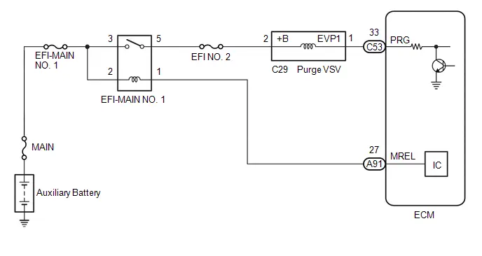
CAUTION / NOTICE / HINT
NOTICE:
- Inspect the fuses for circuits related to this system before performing the following procedure.
-
Toyota Prius Vehicle Control History may be stored in the hybrid vehicle control ECU assembly if the engine is malfunctioning. Certain vehicle condition information is recorded when Vehicle Control History is stored. Reading the vehicle conditions recorded in both the freeze frame data and Vehicle Control History can be useful for troubleshooting.
Click here

(Select Powertrain in Health Check and then check the time stamp data.)
-
If any "Engine Malfunction" Toyota Prius Vehicle Control History item has been stored in the hybrid vehicle control ECU assembly, make sure to clear it. However, as all Vehicle Control History items are cleared simultaneously, if any Vehicle Control History items other than "Engine Malfunction" are stored, make sure to perform any troubleshooting for them before clearing Toyota Prius Vehicle Control History.
Click here

PROCEDURE
| 1. | PERFORM ACTIVE TEST USING GTS (ACTIVATE THE EVAP PURGE VSV) |
Pre-procedure1
| (a) Disconnect the fuel vapor feed hose assembly (canister side) of the purge VSV. |
|
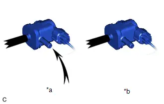
(b) Put the engine in Inspection Mode (Maintenance Mode).
Powertrain > Hybrid Control > Utility| Tester Display |
|---|
| Inspection Mode |
(c) Start the engine.
Procedure1
(d) When the purge VSV is operated using the GTS, check whether the port of the purge VSV applies suction your finger.
Powertrain > Engine > Active Test| Tester Display |
|---|
| Activate the EVAP Purge VSV |
OK:
| GTS Operation | Specified Condition |
|---|---|
| ON | Purge VSV port applies suction to finger |
| OFF | Purge VSV port applies no suction to finger |
HINT:
Jiggle the wire harness and connector to increase the likelihood of detecting malfunctions that do not always occur.
Post-procedure1
(e) None
| OK |

| CHECK FOR INTERMITTENT PROBLEMS |
|

| 2. | INSPECT PURGE VSV |
Click here

| NG |

| REPLACE PURGE VSV |
|

| 3. | CHECK TERMINAL VOLTAGE (POWER SOURCE OF PURGE VSV) |
Pre-procedure1
(a) Disconnect the purge VSV connector.
(b) Turn the ignition switch ON.
Procedure1
(c) Measure the voltage according to the value(s) in the table below.
Standard Voltage:
 Click Location & Routing(C29) Click Connector(C29)
 | Tester Connection | Condition | Specified Condition | Result |
|---|---|---|---|
| C29-2 ( B) - Body ground | Ignition switch ON | 11 to 14 V | V |
Post-procedure1
(d) None
| NG |

| REPAIR OR REPLACE HARNESS OR CONNECTOR (NO. 1 INTEGRATION RELAY - PURGE VSV) |
|

| 4. | CHECK HARNESS AND CONNECTOR (PURGE VSV - ECM) |
Pre-procedure1
(a) Disconnect the purge VSV connector.
(b) Disconnect the ECM connector.
Procedure1
(c) Measure the resistance according to the value(s) in the table below.
Standard Resistance:
 Click Location & Routing(C29,C53) Click Connector(C29) Click Connector(C53)
 | Tester Connection | Condition | Specified Condition | Result |
|---|---|---|---|
| C29-1 (EVP1) - C53-33 (PRG) | Always | Below 1 Ω | Ω |
| C29-1 (EVP1) - C53-33 (PRG) - Body ground and other terminals | Always | 10 kΩ or higher | kΩ |
Post-procedure1
(d) None
| OK |

| REPLACE ECM |
| NG |

| REPAIR OR REPLACE HARNESS OR CONNECTOR |
System Voltage Circuit Short to Ground or Open (P056014)
MONITOR DESCRIPTION
The auxiliary battery supplies electricity to the ECM even when the ignition switch is off. This power allows the ECM to store data such as DTC history, freeze frame data and fuel trim values. If the auxiliary battery voltage falls below a minimum level, the memory is cleared and the ECM determines that there is a malfunction in the power supply circuit. The ECM will illuminate the MIL and store this DTC.
| DTC No. | Detection Item | DTC Detection Condition | Trouble Area | MIL | DTC Output from | Priority | Note |
|---|---|---|---|---|---|---|---|
| P056014 | System Voltage Circuit Short to Ground or Open | An open or short in the ECM backup power source circuit (1 trip detection logic). |
| Comes on | Engine | A | SAE Code: P0562 |
MONITOR STRATEGY
| Required Sensors/Components | ECM |
| Frequency of Operation | Continuous |
TYPICAL MALFUNCTION THRESHOLDS
| Continuous auxiliary battery voltage | Less than 3.5 V |
CONFIRMATION DRIVING PATTERN
- Clear the DTCs (even if no DTCs are stored, perform the clear DTC procedure).
- Turn the ignition switch off and wait for at least 30 seconds.
- Turn the ignition switch ON.
- Wait 5 seconds or more.
- Enter the following menus: Powertrain / Engine / Trouble Codes.
-
Read the pending DTCs.
HINT:
- If a pending DTC is output, the system is malfunctioning.
- If a pending DTC is not output, perform the following procedure.
- Enter the following menus: Powertrain / Engine / Utility / All Readiness.
- Input the DTC: P056014.
-
Check the DTC judgment result.
HINT:
- If the judgment result is NORMAL, the system is normal.
- If the judgment result is ABNORMAL, the system is malfunctioning.
- If the judgment result is INCOMPLETE, perform the Confirmation Driving Pattern and check the DTC judgment result again.
WIRING DIAGRAM
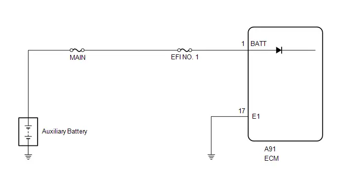
CAUTION / NOTICE / HINT
NOTICE:
- Inspect the fuses for circuits related to this system before performing the following procedure.
-
Toyota Prius Vehicle Control History may be stored in the hybrid vehicle control ECU assembly if the engine is malfunctioning. Certain vehicle condition information is recorded when Vehicle Control History is stored. Reading the vehicle conditions recorded in both the freeze frame data and Vehicle Control History can be useful for troubleshooting.
Click here

(Select Powertrain in Health Check and then check the time stamp data.)
-
If any "Engine Malfunction" Toyota Prius Vehicle Control History item has been stored in the hybrid vehicle control ECU assembly, make sure to clear it. However, as all Vehicle Control History items are cleared simultaneously, if any Vehicle Control History items other than "Engine Malfunction" are stored, make sure to perform any troubleshooting for them before clearing Toyota Prius Vehicle Control History.
Click here

-
After the ignition switch is turned off, there may be a waiting time before disconnecting the negative (-) auxiliary battery terminal.
Click here

-
When disconnecting and reconnecting the auxiliary battery.
HINT:
When disconnecting and reconnecting the auxiliary battery, there is an automatic learning function that completes learning when the respective system is used.
Click here


PROCEDURE
| 1. | INSPECT AUXILIARY BATTERY |
(a) Inspect the auxiliary battery.
Click here

OK:
Auxiliary battery voltage is between 11 to 14 V.
| NG |

| CHARGE OR REPLACE AUXILIARY BATTERY |
|

| 2. | CHECK AUXILIARY BATTERY TERMINAL |
(a) Check that the auxiliary battery terminals are not loose or corroded.
Click here

OK:
Auxiliary battery terminals are not loose or corroded.
| NG |

| REPAIR OR REPLACE AUXILIARY BATTERY TERMINAL |
|

| 3. | CHECK TERMINAL VOLTAGE (POWER SOURCE OF ECM) |
Pre-procedure1
(a) Disconnect the ECM connector.
Procedure1
(b) Measure the voltage according to the value(s) in the table below.
Standard Voltage:
 Click Location & Routing(A91) Click Connector(A91)
 | Tester Connection | Condition | Specified Condition | Result |
|---|---|---|---|
| A91-1 (BATT) - Body ground | Always | 11 to 16 V | V |
Post-procedure1
(c) None
| NG |

| REPAIR OR REPLACE HARNESS OR CONNECTOR (AUXILIARY BATTERY - ECM) |
|

| 4. | CLEAR DTC |
Pre-procedure1
(a) None
Procedure1
(b) Clear the DTCs.
Powertrain > Engine > Clear DTCsPost-procedure1
(c) Turn the ignition switch off and wait for at least 30 seconds.
|

| 5. | CHECK WHETHER DTC OUTPUT RECURS (DTC P056014) |
Pre-procedure1
(a) Wait 5 seconds or more.
Procedure1
(b) Read the DTCs.
Powertrain > Engine > Trouble Codes| Result | Proceed to |
|---|---|
| DTCs are not output | A |
| P056014 is output | B |
Post-procedure1
(c) None
| A |

| CHECK FOR INTERMITTENT PROBLEMS |
| B |

| REPLACE ECM |
Internal Control Module Random Access Memory (RAM) Error Data Memory Failure (P060444)
MONITOR DESCRIPTION
The ECM continuously monitors its internal memory status. This self-check ensures that the ECM is functioning properly. The ECM memory status is diagnosed by internal mirroring of the main CPU and sub CPU to detect Random Access Memory (RAM) errors. If outputs from these CPUs are different and deviate from the standard, the ECM will illuminate the MIL and store this DTC.
| DTC No. | Detection Item | DTC Detection Condition | Trouble Area | MIL | DTC Output from | Priority | Note |
|---|---|---|---|---|---|---|---|
| P060444 | Internal Control Module Random Access Memory (RAM) Error Data Memory Failure | ECM RAM error (1 trip detection logic). | ECM | Comes on | Engine | A | SAE Code: P0604 |
MONITOR STRATEGY
| Required Sensors/Components | ECM |
| Frequency of Operation | Continuous |
CONFIRMATION DRIVING PATTERN
- Clear the DTCs (even if no DTCs are stored, perform the clear DTC procedure).
- Turn the GTS off.
- Turn the ignition switch off.
- Disconnect the GTS.
- Disconnect the cable from the negative (-) auxiliary battery terminal and wait for 1 minute.
- Connect the cable to the negative (-) auxiliary battery terminal.
- Turn the ignition switch ON.
- Wait 16 seconds or more.
- Enter the following menus: Powertrain / Engine / Trouble Codes.
-
Read the pending DTCs.
HINT:
- If a pending DTC is output, the system is malfunctioning.
- If a pending DTC is not output, perform the following procedure.
- Enter the following menus: Powertrain / Engine / Utility / All Readiness.
- Input the DTC: P060444.
-
Check the DTC judgment result.
HINT:
- If the judgment result is NORMAL, the system is normal.
- If the judgment result is ABNORMAL, the system is malfunctioning.
CAUTION / NOTICE / HINT
NOTICE:
-
Toyota Prius Vehicle Control History may be stored in the hybrid vehicle control ECU if the engine is malfunctioning. Certain vehicle condition information is recorded when Vehicle Control History is stored. Reading the vehicle conditions recorded in both the freeze frame data and Vehicle Control History can be useful for troubleshooting.
Click here

(Select Powertrain in Health Check and then check the time stamp data.)
-
If any "Engine Malfunction" Toyota Prius Vehicle Control History item has been stored in the hybrid vehicle control ECU, make sure to clear it. However, as all Vehicle Control History items are cleared simultaneously, if any Vehicle Control History items other than "Engine Malfunction" are stored, make sure to perform any troubleshooting for them before clearing Toyota Prius Vehicle Control History.
Click here

-
After the ignition switch is turned off, there may be a waiting time before disconnecting the negative (-) auxiliary battery terminal.
Click here

-
When disconnecting and reconnecting the auxiliary battery.
HINT:
When disconnecting and reconnecting the auxiliary battery, there is an automatic learning function that completes learning when the respective system is used.
Click here


PROCEDURE
| 1. | CLEAR DTC |
Pre-procedure1
(a) None
Procedure1
(b) Clear the DTCs.
Powertrain > Engine > Clear DTCsPost-procedure1
(c) Turn the ignition switch off.
|

| 2. | READ OUTPUT DTC (DTC P060444) |
Pre-procedure1
(a) Disconnect the cable from the negative (-) auxiliary battery terminal and wait for 1 minute.
(b) Connect the cable to the negative (-) auxiliary battery terminal.
(c) Turn the ignition switch ON.
(d) Wait 16 seconds or more.
Procedure1
(e) Read the DTCs.
Powertrain > Engine > Trouble Codes| Result | Proceed to |
|---|---|
| DTCs are not output | A |
| P060444 is output | B |
Post-procedure1
(f) None
| A |

| CHECK FOR INTERMITTENT PROBLEMS |
| B |

| REPLACE ECM |
Control Module Processor Watchdog/Safety MCU Failure (P060647)
MONITOR DESCRIPTION
The ECM continuously monitors its main and sub CPUs. This self-check ensures that the ECM is functioning properly. If outputs from these CPUs are different and deviate from the standard, the ECM will illuminate the MIL and store this DTC.
| DTC No. | Detection Item | DTC Detection Condition | Trouble Area | MIL | DTC Output from | Priority | Note |
|---|---|---|---|---|---|---|---|
| P060647 | Control Module Processor Watchdog/Safety MCU Failure | ECM main CPU malfunction (1 trip detection logic) | ECM | Comes on | Engine | A | SAE Code: P0606 |
MONITOR STRATEGY
| Required Sensors/Components | ECM |
| Frequency of Operation | Continuous |
CONFIRMATION DRIVING PATTERN
- Clear the DTCs (even if no DTCs are stored, perform the clear DTC procedure).
- Turn the GTS off.
- Turn the ignition switch off.
- Disconnect the GTS.
- Disconnect the cable from the negative (-) auxiliary battery terminal and wait for 1 minute.
- Connect the cable to the negative (-) auxiliary battery terminal.
- Turn the ignition switch ON.
- Wait 1 second or more.
- Enter the following menus: Powertrain / Engine / Trouble Codes.
-
Read the pending DTCs.
HINT:
- If a pending DTC is output, the system is malfunctioning.
- If a pending DTC is not output, perform the following procedure.
- Enter the following menus: Powertrain / Engine / Utility / All Readiness.
- Input the DTC: P060647.
-
Check the DTC judgment result.
HINT:
- If the judgment result is NORMAL, the system is normal.
- If the judgment result is ABNORMAL, the system is malfunctioning.
CAUTION / NOTICE / HINT
NOTICE:
-
Toyota Prius Vehicle Control History may be stored in the hybrid vehicle control ECU assembly if the engine is malfunctioning. Certain vehicle condition information is recorded when Vehicle Control History is stored. Reading the vehicle conditions recorded in both the freeze frame data and Vehicle Control History can be useful for troubleshooting.
Click here

(Select Powertrain in Health Check and then check the time stamp data.)
-
If any "Engine Malfunction" Toyota Prius Vehicle Control History item has been stored in the hybrid vehicle control ECU assembly, make sure to clear it. However, as all Vehicle Control History items are cleared simultaneously, if any Vehicle Control History items other than "Engine Malfunction" are stored, make sure to perform any troubleshooting for them before clearing Toyota Prius Vehicle Control History.
Click here

-
After the ignition switch is turned off, there may be a waiting time before disconnecting the negative (-) auxiliary battery terminal.
Click here

-
When disconnecting and reconnecting the auxiliary battery.
HINT:
When disconnecting and reconnecting the auxiliary battery, there is an automatic learning function that completes learning when the respective system is used.
Click here


PROCEDURE
| 1. | CLEAR DTC |
Pre-procedure1
(a) None
Procedure1
(b) Clear the DTCs.
Powertrain > Engine > Clear DTCsPost-procedure1
(c) Turn the ignition switch off.
|

| 2. | READ OUTPUT DTC (DTC P060647) |
Pre-procedure1
(a) Disconnect the cable from the negative (-) auxiliary battery terminal and wait for 1 minute.
(b) Connect the cable to the negative (-) auxiliary battery terminal.
(c) Turn the ignition switch ON.
(d) Wait 1 second or more.
Procedure1
(e) Read the DTCs.
Powertrain > Engine > Trouble Codes| Result | Proceed to |
|---|---|
| DTCs are not output | A |
| P060647 is output | B |
Post-procedure1
(f) None
| A |

| CHECK FOR INTERMITTENT PROBLEMS |
| B |

| REPLACE ECM |
Control Module Performance Bank 1 Watchdog/Safety MCU Failure (P060747,P060787)
MONITOR DESCRIPTION
The ECM continuously monitors its internal ICs and the monitor IC. If the monitor IC is abnormal, the ECM illuminates the MIL and stores DTC P060747. If an internal IC is abnormal, the ECM illuminates the MIL and stores DTC P060787.
| DTC No. | Detection Item | DTC Detection Condition | Trouble Area | MIL | DTC Output from | Priority | Note |
|---|---|---|---|---|---|---|---|
| P060747 | Control Module Performance Bank 1 Watchdog/Safety MCU Failure | ECM monitor IC malfunction (1 trip detection logic). | ECM | Comes on | Engine | A | SAE Code: P0607 |
| P060787 | Control Module Performance Bank 1 Missing Message | ECM internal IC malfunction (1 trip detection logic). | ECM | Comes on | Engine | A | SAE Code: P0607 |
MONITOR STRATEGY
| Required Sensors/Components | ECM |
| Frequency of Operation | Continuous |
CONFIRMATION DRIVING PATTERN
- Clear the DTCs (even if no DTCs are stored, perform the clear DTC procedure).
- Turn the GTS off.
- Turn the ignition switch off.
- Disconnect the GTS.
- Disconnect the cable from the negative (-) auxiliary battery terminal and wait for 1 minute.
- Connect the cable to the negative (-) auxiliary battery terminal.
- Turn the ignition switch ON.
- Wait 1 second or more [A].
- Enter the following menus: Powertrain / Engine / Trouble Codes [B].
-
Read the pending DTCs.
HINT:
- If a pending DTC is output, the system is malfunctioning.
- If a pending DTC is not output, perform the following procedure.
- Enter the following menus: Powertrain / Engine / Utility / All Readiness.
- Input the DTC: P060747 or P060787
-
Check the DTC judgment result.
HINT:
- If the judgment result is NORMAL, the system is normal.
- If the judgment result is ABNORMAL, the system is malfunctioning.
-
[A] to [B]: Normal judgment procedure.
The normal judgment procedure is used to complete DTC judgment and also used when clearing permanent DTCs.
- When clearing the permanent DTCs, do not disconnect the cable from the auxiliary battery terminal or attempt to clear the DTCs during this procedure, as doing so will clear the universal trip and normal judgment histories.
CAUTION / NOTICE / HINT
NOTICE:
-
Toyota Prius Vehicle Control History may be stored in the hybrid vehicle control ECU if the engine is malfunctioning. Certain vehicle condition information is recorded when Vehicle Control History is stored. Reading the vehicle conditions recorded in both the freeze frame data and Vehicle Control History can be useful for troubleshooting.
Click here

(Select Powertrain in Health Check and then check the time stamp data.)
-
If any "Engine Malfunction" Toyota Prius Vehicle Control History item has been stored in the hybrid vehicle control ECU, make sure to clear it. However, as all Vehicle Control History items are cleared simultaneously, if any Vehicle Control History items other than "Engine Malfunction" are stored, make sure to perform any troubleshooting for them before clearing Toyota Prius Vehicle Control History.
Click here

-
After the ignition switch is turned off, there may be a waiting time before disconnecting the negative (-) auxiliary battery terminal.
Click here

-
When disconnecting and reconnecting the auxiliary battery.
HINT:
When disconnecting and reconnecting the auxiliary battery, there is an automatic learning function that completes learning when the respective system is used.
Click here


PROCEDURE
| 1. | CLEAR DTC |
Pre-procedure1
(a) None
Procedure1
(b) Clear the DTCs.
Powertrain > Engine > Clear DTCsPost-procedure1
(c) Turn the ignition switch off.
|

| 2. | READ OUTPUT DTC (DTC P060747 OR P060787) |
Pre-procedure1
(a) Disconnect the cable from the negative (-) auxiliary battery terminal and wait for 1 minute.
(b) Connect the cable to the negative (-) auxiliary battery terminal.
(c) Wait 1 second or more.
Procedure1
(d) Read the DTCs.
Powertrain > Engine > Trouble Codes| Result | Proceed to |
|---|---|
| DTCs are not output | A |
| P060747 or P060787 is output | B |
Post-procedure1
(e) None
| A |

| CHECK FOR INTERMITTENT PROBLEMS |
| B |

| REPLACE ECM |
Internal Control Module Throttle Position Performance Internal Electronic Failure (P060E49)
MONITOR DESCRIPTION
The ECM monitors the signals received from the No. 1 throttle position sensor. As the ECM monitors the VTA1 signal of the No. 1 throttle position sensor, if these signals do not correlate, a DTC will be stored.
| DTC No. | Detection Item | DTC Detection Condition | Trouble Area | MIL | DTC Output from | Priority | Note |
|---|---|---|---|---|---|---|---|
| P060E49 | Internal Control Module Throttle Position Performance Internal Electronic Failure | Either of the following conditions is met (1 trip detection logic):
| ECM | Comes on | Engine | A | SAE Code: P060E |
MONITOR STRATEGY
| Required Sensors/Components | ECM |
| Frequency of Operation | Continuous |
CONFIRMATION DRIVING PATTERN
- Clear the DTCs (even if no DTCs are stored, perform the clear DTC procedure).
- Turn the GTS off.
- Turn the ignition switch off.
- Disconnect the GTS.
- Disconnect the cable from the negative (-) auxiliary battery terminal and wait for 1 minute.
- Connect the cable to the negative (-) auxiliary battery terminal.
- Connect the GTS to the DLC3.
- Turn the ignition switch ON.
- Wait 16 seconds or more.
- Enter the following menus: Powertrain / Engine / Trouble Codes.
-
Read the pending DTCs.
HINT:
- If a pending DTC is output, the system is malfunctioning.
- If a pending DTC is not output, perform the following procedure.
- Enter the following menus: Powertrain / Engine / Utility / All Readiness.
- Input the DTC: P060E49.
-
Check the DTC judgment result.
HINT:
- If the judgment result is NORMAL, the system is normal.
- If the judgment result is ABNORMAL, the system is malfunctioning.
CAUTION / NOTICE / HINT
NOTICE:
-
Toyota Prius Vehicle Control History may be stored in the hybrid vehicle control ECU if the engine is malfunctioning. Certain vehicle condition information is recorded when Vehicle Control History is stored. Reading the vehicle conditions recorded in both the freeze frame data and Vehicle Control History can be useful for troubleshooting.
Click here

(Select Powertrain in Health Check and then check the time stamp data.)
-
If any "Engine Malfunction" Toyota Prius Vehicle Control History item has been stored in the hybrid vehicle control ECU, make sure to clear it. However, as all Vehicle Control History items are cleared simultaneously, if any Vehicle Control History items other than "Engine Malfunction" are stored, make sure to perform any troubleshooting for them before clearing Toyota Prius Vehicle Control History.
Click here

-
After the ignition switch is turned off, there may be a waiting time before disconnecting the negative (-) auxiliary battery terminal.
Click here

-
When disconnecting and reconnecting the auxiliary battery.
HINT:
When disconnecting and reconnecting the auxiliary battery, there is an automatic learning function that completes learning when the respective system is used.
Click here


PROCEDURE
| 1. | CLEAR DTC |
Pre-procedure1
(a) None
Procedure1
(b) Clear the DTCs.
Powertrain > Engine > Clear DTCsPost-procedure1
(c) Turn the ignition switch off.
|

| 2. | READ OUTPUT DTC (DTC P060E49) |
Pre-procedure1
(a) Disconnect the cable from the negative (-) auxiliary battery terminal and wait for 1 minute.
(b) Connect the cable to the negative (-) auxiliary battery terminal.
(c) Turn the ignition switch ON.
(d) Wait 16 seconds or more.
Procedure1
(e) Read the DTCs.
Powertrain > Engine > Trouble Codes| Result | Proceed to |
|---|---|
| DTCs are not output | A |
| P060E49 is output | B |
Post-procedure1
(f) None
| A |

| CHECK FOR INTERMITTENT PROBLEMS |
| B |

| REPLACE ECM |
VIN Not Programmed (P063051)
MONITOR DESCRIPTION
DTC P063051 is stored when the Vehicle Identification Number (VIN) or frame number is not stored in the ECM or the stored VIN or frame number is not accurate.
| DTC No. | Detection Item | DTC Detection Condition | Trouble Area | MIL | DTC Output from | Priority | Note |
|---|---|---|---|---|---|---|---|
| P063051 | VIN Not Programmed | Either of the following conditions is met (1 trip detection logic).
|
| Comes on | Engine | B | SAE Code: P0630 |
MONITOR STRATEGY
| Required Sensors/Components | ECM |
| Frequency of Operation | Continuous |
CONFIRMATION DRIVING PATTERN
- Clear the DTCs (even if no DTCs are stored, perform the clear DTC procedure).
- Turn the ignition switch off and wait for at least 30 seconds.
- Turn the ignition switch ON.
- Wait 5 seconds or more.
- Enter the following menus: Powertrain / Engine / Trouble Codes.
-
Read the pending DTCs.
HINT:
- If a pending DTC is output, the system is malfunctioning.
- If a pending DTC is not output, perform the following procedure.
- Enter the following menus: Powertrain / Engine / Utility / All Readiness.
- Input the DTC: P063051.
-
Check the DTC judgment result.
HINT:
- If the judgment result is NORMAL, the system is normal.
- If the judgment result is ABNORMAL, the system is malfunctioning.
CAUTION / NOTICE / HINT
NOTICE:
-
Toyota Prius Vehicle Control History may be stored in the hybrid vehicle control ECU assembly if the engine is malfunctioning. Certain vehicle condition information is recorded when Vehicle Control History is stored. Reading the vehicle conditions recorded in both the freeze frame data and Vehicle Control History can be useful for troubleshooting.
Click here

(Select Powertrain in Health Check and then check the time stamp data.)
-
If any "Engine Malfunction" Toyota Prius Vehicle Control History item has been stored in the hybrid vehicle control ECU assembly, make sure to clear it. However, as all Vehicle Control History items are cleared simultaneously, if any Vehicle Control History items other than "Engine Malfunction" are stored, make sure to perform any troubleshooting for them before clearing Toyota Prius Vehicle Control History.
Click here

PROCEDURE
| 1. | CHECK ANY OTHER DTCS OUTPUT (IN ADDITION TO DTC P063051) |
(a) Read the DTCs.
Powertrain > Engine > Trouble CodesNOTICE:
If P063051 is output, the VIN or frame number must be written to the ECM using the GTS. However, all DTCs are cleared automatically by the GTS when the VIN or frame number is written. If DTCs other than P063051 are output, troubleshoot them first.
| Result | Proceed to |
|---|---|
| P063051 and other DTCs are output | A |
| P063051 is output | B |
| A |

| GO TO DTC CHART |
|

| 2. | WRITE VIN OR FRAME NUMBER |
(a) Write the VIN or frame number.
Click here

| NEXT |

| END |
Actuator Supply Voltage "A" Circuit Short to Ground or Open (P065714)
DESCRIPTION
The electronic throttle control system has a dedicated power supply circuit. The voltage ( BM) is monitored and when it is low (less than 4 V), the ECM determines that there is a malfunction in the electronic throttle control system and cuts off the current to the throttle actuator.
When the voltage becomes unstable, the electronic throttle control system itself becomes unstable. For this reason, when the voltage is low, the current to the throttle actuator is cut. If repairs are made and the system returns to normal, turn the ignition switch off. The ECM then allows the current to flow to the throttle actuator so that it can be restarted.
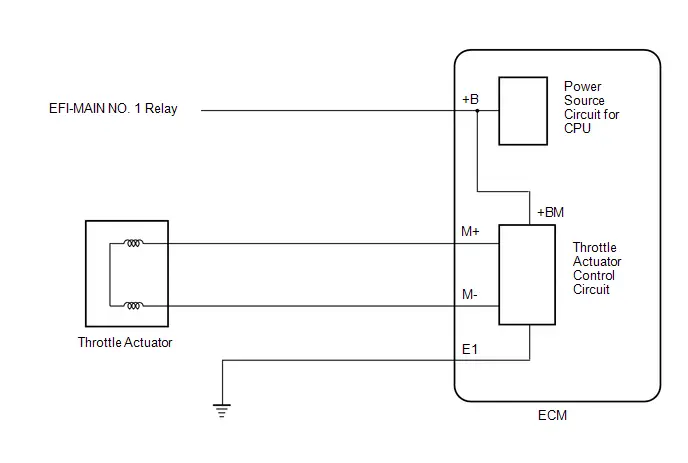
| DTC No. | Detection Item | DTC Detection Condition | Trouble Area | MIL | DTC Output from | Priority | Note |
|---|---|---|---|---|---|---|---|
| P065714 | Actuator Supply Voltage "A" Circuit Short to Ground or Open | An open or short is detected in the electronic throttle control system power source ( BM) circuit (1 trip detection logic). |
| Comes on | Engine | A | SAE Code: P0658 |
MONITOR DESCRIPTION
The ECM monitors the auxiliary battery supply voltage applied to the throttle actuator.
When the power supply voltage ( BM) is less than 4 V for 0.8 seconds or more, the ECM interprets this as an open or ground short in the power supply circuit, then illuminates the MIL and stores this DTC.
MONITOR STRATEGY
| Required Sensors/Components | Throttle actuator Throttle valve (throttle body assembly) |
| Frequency of Operation | Continuous |
CONFIRMATION DRIVING PATTERN
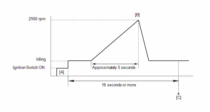
- Clear the DTCs (even if no DTCs are stored, perform the clear DTC procedure).
- Turn the ignition switch off and wait for at least 30 seconds.
- Turn the ignition switch ON [A].
-
Put the engine in Inspection Mode (Maintenance Mode).
Click here

- Start the engine.
-
Slowly depress the accelerator pedal, raise the engine speed to approximately 2500 rpm over approximately 5 seconds, and then idle the engine [B].
HINT:
During charge control, the engine speed is set at idle. Therefore, the engine speed will not increase when the accelerator pedal is depressed. In this case, perform step [B] after charge control has completed.
- Check that 16 seconds or more have elapsed since the engine was started.
- Enter the following menus: Powertrain / Engine / Trouble Codes [C].
-
Read the pending DTCs.
HINT:
- If a pending DTC is output, the system is malfunctioning.
- If a pending DTC is not output, perform the following procedure.
- Enter the following menus: Powertrain / Engine / Utility / All Readiness.
- Input the DTC: P065714.
-
Check the DTC judgment result.
HINT:
- If the judgment result is NORMAL, the system is normal.
- If the judgment result is ABNORMAL, the system is malfunctioning.
- If the judgment result is INCOMPLETE, perform steps [B] and [C] again.
FAIL-SAFE
When this DTC is stored, the ECM enters fail-safe mode. During fail-safe mode, the ECM cuts the current to the throttle actuator, and the throttle valve is returned to a 5.5° throttle valve opening angle by the return spring. The ECM then adjusts the engine output, by controlling the fuel injection (intermittent fuel cut) and ignition timing, in accordance with the engine torque request signal sent from the hybrid Toyota Prius vehicle control ECU, to allow the vehicle to continue being driven at a minimal speed. If the accelerator pedal is depressed firmly and gently, the vehicle can be driven slowly.
Fail-safe mode continues until a pass condition is detected, and the ignition switch is then turned off.
WIRING DIAGRAM
Refer to DTC P210018.
Click here

CAUTION / NOTICE / HINT
NOTICE:
- Inspect the fuses for circuits related to this system before performing the following procedure.
-
Toyota Prius Vehicle Control History may be stored in the hybrid vehicle control ECU if the engine is malfunctioning. Certain vehicle condition information is recorded when Vehicle Control History is stored. Reading the vehicle conditions recorded in both the freeze frame data and Vehicle Control History can be useful for troubleshooting.
Click here

(Select Powertrain in Health Check and then check the time stamp data.)
-
If any "Engine Malfunction" Toyota Prius Vehicle Control History item has been stored in the hybrid vehicle control ECU, make sure to clear it. However, as all Vehicle Control History items are cleared simultaneously, if any Vehicle Control History items other than "Engine Malfunction" are stored, make sure to perform any troubleshooting for them before clearing Toyota Prius Vehicle Control History.
Click here

PROCEDURE
| 1. | CHECK ANY OTHER DTCS OUTPUT (IN ADDITION TO DTC P065714) |
(a) Read the DTCs.
Powertrain > Engine > Trouble Codes| Result | Proceed to |
|---|---|
| P065714 is output | A |
| DTCs are not output | B |
| A |

| REPLACE ECM |
| B |

| CHECK FOR INTERMITTENT PROBLEMS |
Throttle Actuator "A" Control Motor Circuit Current Below Threshold (P210018,P210019)
DESCRIPTION
The throttle actuator is operated by the ECM and opens and closes the throttle valve using gears.
The opening angle of the throttle valve is detected by the throttle position sensor, which is built into the throttle body assembly. The throttle position sensor provides feedback to the ECM. This feedback allows the ECM to appropriately control the throttle actuator and monitor the throttle opening angle as the ECM responds to a request from the hybrid system.
| DTC No. | Detection Item | DTC Detection Condition | Trouble Area | MIL | DTC Output from | Priority | Note |
|---|---|---|---|---|---|---|---|
| P210018 | Throttle Actuator "A" Control Motor Circuit Current Below Threshold | Both of the following conditions are met for 2 seconds or more (1 trip detection logic):
|
| Comes on | Engine | A | SAE Code: P2102 |
| P210019 | Throttle Actuator "A" Control Motor Circuit Current Above Threshold | Either of the following conditions is met (1 trip detection logic):
|
| Comes on | Engine | A | SAE Code: P2103 |
MONITOR DESCRIPTION
The ECM monitors the electrical current through the electronic actuator, and detects malfunctions and open circuits in the throttle actuator based on this value. If the current is outside the standard range, the ECM determines that there is a malfunction in the throttle actuator. In addition, if the throttle valve does not operate properly (for example, it is stuck open), the ECM will determines there is a malfunction, illuminate the MIL and store a DTC.
MONITOR STRATEGY
| Required Sensors/Components | Throttle actuator (throttle body assembly) |
| Frequency of Operation | Continuous |
CONFIRMATION DRIVING PATTERN
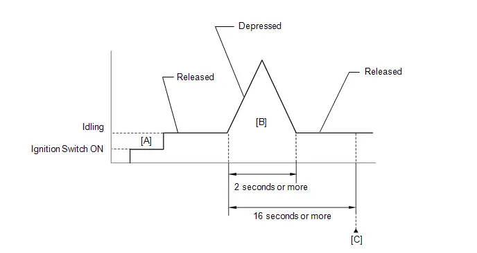
- Clear the DTCs (even if no DTCs are stored, perform the clear DTC procedure).
- Turn the ignition switch off and wait for at least 30 seconds.
- Turn the ignition switch ON [A].
-
Put the engine in Inspection Mode (Maintenance Mode).
Click here

- Start the engine.
-
With the Toyota Prius vehicle stationary, fully depress the accelerator pedal and quickly release it [B].
HINT:
During charge control, the engine speed is set at idle. Therefore, the engine speed will not increase when the accelerator pedal is depressed. In this case, perform step [B] after charge control has completed.
- Check that 16 seconds or more have elapsed since the accelerator pedal was first depressed.
- Enter the following menus: Powertrain / Engine / Trouble Codes [C].
-
Read the pending DTCs.
HINT:
- If a pending DTC is output, the system is malfunctioning.
- If a pending DTC is not output, perform the following procedure.
- Enter the following menus: Powertrain / Engine / Utility / All Readiness.
- Input the DTC: P210018 or P210019.
-
Check the DTC judgment result.
HINT:
- If the judgment result is NORMAL, the system is normal.
- If the judgment result is ABNORMAL, the system is malfunctioning.
- If the judgment result is INCOMPLETE, perform steps [B] and [C] again.
FAIL-SAFE
When this DTC is stored, the ECM enters fail-safe mode. During fail-safe mode, the ECM cuts the current to the throttle actuator, and the throttle valve is returned to a 5.5° throttle valve opening angle by the return spring. The ECM then adjusts the engine output, by controlling the fuel injection (intermittent fuel cut) and ignition timing, in accordance with the engine torque request signal sent from the hybrid Toyota Prius vehicle control ECU, to allow the vehicle to continue being driven at a minimal speed. If the accelerator pedal is depressed firmly and gently, the vehicle can be driven slowly.
Fail-safe mode continues until a pass condition is detected, and the ignition switch is then turned off.
WIRING DIAGRAM

CAUTION / NOTICE / HINT
NOTICE:
- Inspect the fuses for circuits related to this system before performing the following procedure.
-
Toyota Prius Vehicle Control History may be stored in the hybrid vehicle control ECU if the engine is malfunctioning. Certain vehicle condition information is recorded when Vehicle Control History is stored. Reading the vehicle conditions recorded in both the freeze frame data and Vehicle Control History can be useful for troubleshooting.
Click here

(Select Powertrain in Health Check and then check the time stamp data.)
-
If any "Engine Malfunction" Toyota Prius Vehicle Control History item has been stored in the hybrid vehicle control ECU, make sure to clear it. However, as all Vehicle Control History items are cleared simultaneously, if any Vehicle Control History items other than "Engine Malfunction" are stored, make sure to perform any troubleshooting for them before clearing Toyota Prius Vehicle Control History.
Click here

HINT:
The throttle actuator current (Throttle Motor Current) and the throttle actuator duty ratio (Throttle Motor Duty Ratio (Open) / Throttle Motor Duty Ratio (Close)) can be read using the GTS. However, the ECM shuts off the throttle actuator current when the electronic throttle control system malfunctions.
PROCEDURE
| 1. | INSPECT THROTTLE BODY ASSEMBLY (RESISTANCE OF THROTTLE ACTUATOR) |
Click here

| NG |

| REPLACE THROTTLE BODY ASSEMBLY |
|

| 2. | CHECK HARNESS AND CONNECTOR (THROTTLE BODY ASSEMBLY - ECM) |
Pre-procedure1
(a) Disconnect the throttle body assembly connector.
(b) Disconnect the ECM connector.
Procedure1
(c) Measure the resistance according to the value(s) in the table below.
Standard Resistance:
 Click Location & Routing(C24,C53) Click Connector(C24) Click Connector(C53)
 | Tester Connection | Condition | Specified Condition | Result |
|---|---|---|---|
| C24-2 (M ) - C53-29 (M ) | Always | Below 1 Ω | Ω |
| C24-1 (M-) - C53-30 (M-) | Always | Below 1 Ω | Ω |
| C24-2 (M ) or C53-29 (M ) - Body ground and other terminals | Always | 10 kΩ or higher | kΩ |
| C24-1 (M-) or C53-30 (M-) - Body ground and other terminals | Always | 10 kΩ or higher | kΩ |
Post-procedure1
(d) None
| NG |

| REPAIR OR REPLACE HARNESS OR CONNECTOR |
|

| 3. | INSPECT THROTTLE BODY ASSEMBLY (VISUALLY CHECK THROTTLE VALVE) |
(a) Check for foreign matter between the throttle valve and the housing.
OK:
No foreign matter between the throttle valve and housing.
HINT:
Perform "Inspection After Repair" after cleaning the throttle body assembly.
Click here

| NG |

| REMOVE FOREIGN MATTER AND CLEAN THROTTLE BODY ASSEMBLY |
|

| 4. | INSPECT THROTTLE BODY ASSEMBLY (THROTTLE VALVE) |
(a) Check if the throttle valve opens and closes smoothly.
OK:
Throttle valve opens and closes smoothly.
| OK |

| REPLACE ECM |
| NG |

| REPLACE THROTTLE BODY ASSEMBLY |
Throttle/Pedal Position Sensor "A" Minimum Stop Performance (P210900)
DESCRIPTION
The idle speed is controlled by the Electronic Throttle Control System (ETCS). The ETCS is comprised of a throttle actuator, which operates the throttle valve, and a throttle position sensor, which detects the opening amount of the throttle valve. The ECM controls the throttle actuator to adjust the throttle valve opening amount so that the idle speed is maintained at the target idle speed.
| DTC No. | Detection Item | DTC Detection Condition | Trouble Area | MIL | DTC Output from | Priority | Note |
|---|---|---|---|---|---|---|---|
| P210900 | Throttle/Pedal Position Sensor "A" Minimum Stop Performance | The ISC learned value is approximately 3 times larger than normal even though the actual intake air amount during idle is within the normal range (up to 1.5 times the normal amount) (1 trip detection logic). | Throttle body assembly | Does not come on | Engine | B | SAE Code: P2109 |
HINT:
- The ISC learned value is the calculated intake air amount corresponding to the throttle opening amount necessary to maintain the idling speed.
- This malfunction is only detected once per trip. After it has been detected once, the system will not monitor for the malfunction for the rest of the trip.
- The system uses the throttle body assembly and mass air flow meter sub-assembly to detect this malfunction.
MONITOR DESCRIPTION
If there are deposits in the throttle valve, a decrease in the ISC flow rate may cause engine stall or unstable idling. Therefore, the necessary ISC flow rate for idling is maintained using the ISC learned value and feedback. The ECM stores this DTC if the ISC learned value approaches its limit. The ECM begins monitoring for the DTC detection conditions when the following preconditions are met:
- The mass air flow meter sub-assembly is normal.
- Atmospheric pressure is 85 kPa(abs) [12.3 psi(abs)] or higher.
- The Toyota Prius vehicle has been driven at a speed of 30 km/h (19 mph) or more at least once.
- The engine coolant temperature is 45°C (113°F) or less at engine start, the engine is warmed up and conditions for ISC learning are met, or the ignition switch has been turned ON (READY) (including when the engine is running) for 1 hour or more, the engine is warmed up and conditions for ISC learning are met.
CAUTION / NOTICE / HINT
NOTICE:
-
Toyota Prius Vehicle Control History may be stored in the hybrid vehicle control ECU assembly if the engine is malfunctioning. Certain vehicle condition information is recorded when Vehicle Control History is stored. Reading the vehicle conditions recorded in both the freeze frame data and Vehicle Control History can be useful for troubleshooting.
Click here

(Select Powertrain in Health Check and then check the time stamp data.)
-
If any "Engine Malfunction" Toyota Prius Vehicle Control History item has been stored in the hybrid vehicle control ECU assembly, make sure to clear it. However, as all Vehicle Control History items are cleared simultaneously, if any Vehicle Control History items other than "Engine Malfunction" are stored, make sure to perform any troubleshooting for them before clearing Toyota Prius Vehicle Control History.
Click here

HINT:
Since a pending DTC is not stored for this DTC, it takes time to confirm whether the malfunction has been successfully repaired by checking for this DTC. When confirming whether the malfunction has been successfully repaired, compare "ISC Learning Value" recorded in the freeze frame data with "ISC Learning Value" in the Data List after repairs have been made to save time.
PROCEDURE
| 1. | CHECK ANY OTHER DTCS OUTPUT (IN ADDITION TO DTC P210900) |
(a) Read the DTCs.
Powertrain > Engine > Trouble Codes| Result | Proceed to |
|---|---|
| P210900 and other DTCs are output | A |
| P210900 is output | B |
HINT:
If any DTCs other than P210900 are output, troubleshoot those DTCs first.
| A |

| GO TO DTC CHART |
|

| 2. | READ FREEZE FRAME DATA (ISC LEARNING VALUE) |
(a) Using the GTS, check "ISC Learning Value" in the freeze frame data.
HINT:
-
Click here

- Be sure to confirm that the freeze frame date item "ISC Learning Value" is the same as that used when confirming whether the malfunction has been successfully repaired.
|

| 3. | INSPECT THROTTLE BODY ASSEMBLY |
(a) Check for foreign matter between the throttle valve and the housing.
| *1 | Throttle Body Assembly | *2 | Bore |
| *3 | Throttle Valve | - | - |
| *a | Reference | *b | Throttle Body Assembly Cross-section Diagram |
| *c | When valve fully opened | *d | Deposits |
HINT:
The illustration is for reference only, actual parts may differ.
| Result | Proceed to |
|---|---|
| Foreign matter between the throttle valve and housing | A |
| No foreign matter between the throttle valve and housing | B |
| B |

| REPLACE THROTTLE BODY ASSEMBLY |
|

| 4. | REMOVE FOREIGN MATTER (CLEAN THROTTLE BODY ASSEMBLY) |
(a) Clean off any deposits inside of the throttle body assembly.
| *1 | Throttle Body Assembly | *2 | Bore |
| *3 | Throttle Valve | - | - |
| *a | Reference | *b | Throttle Body Assembly Cross-section Diagram |
| *c | When valve fully opened | *d | Do not directly apply cleaner |
| *e | Deposits | - | - |
(1) Push open the throttle valve and wipe off any deposits from the valve and bore using a cloth soaked in non-residue solvent.
NOTICE:
- Make sure that the cloth or your fingers do not get caught in the valve.
- Make sure that foreign matter does not enter the throttle valve.
- Do not directly apply non-residue solvent to the throttle body assembly or wash the throttle body assembly. Cleaning solvent may leak into the motor from the shaft and cause problems such as rust or valve movement problems.
- If there is coating material on the edge of the throttle valve, be careful not to remove it.
- Push the throttle valve open gently with your finger and check that the throttle valve moves smoothly.
HINT:
-
If the throttle valve does not open smoothly, replace the throttle body assembly.
Click here

- The illustration is for reference only, actual parts may differ.
|

| 5. | READ VALUE USING GTS (ISC LEARNING VALUE) |
Pre-procedure1
(a) Perform "Inspection After Repair" after cleaning the throttle body assembly.
HINT:
Click here

Procedure1
(b) According to the display on the GTS, read the Data List.
Powertrain > Engine > Data List| Tester Display |
|---|
| ISC Learning Value |
OK:
The value of ISC Learning Value is half or less of ISC Learning Value recorded in the freeze frame data.
Post-procedure1
(c) None
| OK |

| END |
| NG |

| REPLACE THROTTLE BODY ASSEMBLY |
Throttle Actuator "A" Control System Actuator Stuck Open (P211172,P211173)
DESCRIPTION
The throttle actuator is operated by the ECM and opens and closes the throttle valve using gears. The opening angle of the throttle valve is detected by the throttle position sensor, which is built into the throttle body assembly. The throttle position sensor provides feedback to the ECM. This feedback allows the ECM to appropriately control the throttle actuator and monitor the throttle opening angle as the ECM responds to a request from the hybrid system.
| DTC No. | Detection Item | DTC Detection Condition | Trouble Area | MIL | DTC Output from | Priority | Note |
|---|---|---|---|---|---|---|---|
| P211172 | Throttle Actuator "A" Control System Actuator Stuck Open | The ECM signals the throttle actuator to close, but the actuator is stuck (1 trip detection logic). |
| Comes on | Engine | B | SAE Code: P2111 |
| P211173 | Throttle Actuator "A" Control System Actuator Stuck Closed | The ECM signals the throttle actuator to open, but the actuator is stuck (1 trip detection logic). |
| Comes on | Engine | B | SAE Code: P2112 |
MONITOR DESCRIPTION
If throttle valve remains at a certain angle despite a high drive current from the ECM, the ECM determines that there is a malfunction in the ETCS, illuminates the MIL and stores a DTC.
MONITOR STRATEGY
| Required Sensors/Components | Throttle actuator (throttle body assembly) |
| Frequency of Operation | Continuous |
TYPICAL ENABLING CONDITIONS
P2111: Throttle Actuator Stuck Open| All of the following conditions are met | - |
| System guard* judge condition | On |
| Throttle actuator current | 2 A or higher |
| Duty-cycle to close throttle | 80% or higher |
| All of the following conditions are met | - |
| System guard* judge condition | On |
| Throttle actuator current | 2 A or higher |
| Duty-cycle to open throttle | 80% or higher |
| *: System guard set when following conditions are met | - |
| Throttle actuator | On |
| Throttle actuator duty calculation | Executing |
| Throttle position sensor fail | Not detected |
| Throttle actuator current-cut operation | Not executing |
| Throttle actuator power supply | 4 V or higher |
| Throttle actuator fail | Not detected |
TYPICAL MALFUNCTION THRESHOLDS
P2111: Throttle Actuator Stuck Open| Throttle position sensor voltage | No change |
| Throttle position sensor voltage | No change |
CONFIRMATION DRIVING PATTERN
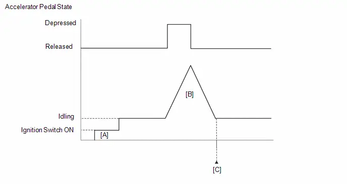
- Clear the DTCs (even if no DTCs are stored, perform the clear DTC procedure).
- Turn the ignition switch off and wait for at least 30 seconds.
- Turn the ignition switch ON [A].
- Turn the GTS on.
-
Put the engine in Inspection Mode (Maintenance Mode).
Click here

-
Start the engine and depress and release the accelerator pedal quickly (to open and close the throttle valve) [B].
HINT:
During charge control, the engine speed is set at idle. Therefore, the engine speed will not increase when the accelerator pedal is depressed. In this case, perform step [B] after charge control has completed.
- Enter the following menus: Powertrain / Engine / Trouble Codes [C].
-
Read the pending DTCs.
HINT:
- If a pending DTC is output, the system is malfunctioning.
- If a pending DTC is not output, perform the following procedure.
- Enter the following menus: Powertrain / Engine / Utility / All Readiness.
- Input the DTC: P211172 or P211173.
-
Check the DTC judgment result.
HINT:
- If the judgment result is NORMAL, the system is normal.
- If the judgment result is ABNORMAL, the system is malfunctioning.
FAIL-SAFE
When these DTCs or other DTCs relating to Electronic Throttle Control System (ETCS) malfunctions are stored, the ECM enters fail-safe mode. During fail-safe mode, the ECM cuts the current to the throttle actuator, and the throttle valve is returned to a 5.5° throttle valve opening angle by the return spring. The ECM stops the engine and the Toyota Prius vehicle can be driven using solely the hybrid system. If the accelerator pedal is depressed firmly and gently, the vehicle can be driven slowly.
Fail-safe mode continues until a pass condition is detected, and the ignition switch is then turned off.
WIRING DIAGRAM
Refer to DTC P210018.
Click here

CAUTION / NOTICE / HINT
NOTICE:
-
Toyota Prius Vehicle Control History may be stored in the hybrid vehicle control ECU if the engine is malfunctioning. Certain vehicle condition information is recorded when Vehicle Control History is stored. Reading the vehicle conditions recorded in both the freeze frame data and Vehicle Control History can be useful for troubleshooting.
Click here

(Select Powertrain in Health Check and then check the time stamp data.)
-
If any "Engine Malfunction" Toyota Prius Vehicle Control History item has been stored in the hybrid vehicle control ECU, make sure to clear it. However, as all Vehicle Control History items are cleared simultaneously, if any Vehicle Control History items other than "Engine Malfunction" are stored, make sure to perform any troubleshooting for them before clearing Toyota Prius Vehicle Control History.
Click here

HINT:
Refer to "Data List / Active Test" [Throttle Position Sensor No.1 Voltage, Throttle Position Sensor No.2 Voltage, Throttle Position Command, Throttle Motor Current, Throttle Motor Duty Ratio (Open) and Throttle Motor Duty Ratio (Close)].
Click here

PROCEDURE
| 1. | CHECK ANY OTHER DTCS OUTPUT (IN ADDITION TO DTC P211172 OR P211173) |
(a) Read the DTCs.
Powertrain > Engine > Trouble Codes| Result | Proceed to |
|---|---|
| P211172 or P211173 and other DTCs are output | A |
| P211172 or P211173 is output | B |
HINT:
If any DTCs other than P211172 or P211173 are output, troubleshoot those DTCs first.
| A |

| GO TO DTC CHART |
|

| 2. | INSPECT THROTTLE BODY ASSEMBLY (VISUALLY CHECK THROTTLE VALVE) |
(a) Check for foreign matter between the throttle valve and housing. If necessary, clean the throttle body assembly. Also check that the throttle valve moves smoothly.
OK:
Throttle valve is not contaminated with foreign matter and moves smoothly.
HINT:
Perform "Inspection After Repair" after cleaning the throttle body assembly.
Click here

| NG |

| GO TO STEP 6 |
|

| 3. | CLEAR DTC |
Pre-procedure1
(a) None
Procedure1
(b) Clear the DTCs.
Powertrain > Engine > Clear DTCsPost-procedure1
(c) Turn the ignition switch off and wait for at least 30 seconds.
|

| 4. | READ VALUE USING GTS (THROTTLE POSITION) |
(a) Read the values displayed on the GTS while wiggling the ECM wire harness.
Powertrain > Engine > Data List| Tester Display |
|---|
| Throttle Position Sensor No.1 Voltage |
| Throttle Position Sensor No.2 Voltage |
| Throttle Position Command |
(b) Read the DTCs.
Powertrain > Engine > Trouble Codes| Result | Proceed to |
|---|---|
| Value in Data List changes when wire harness is wiggled, or DTC is output | A |
| Other than above | B |
| B |

| GO TO STEP 7 |
|

| 5. | REPAIR OR REPLACE HARNESS OR CONNECTOR (THROTTLE BODY ASSEMBLY - ECM) |
(a) As the DTC was stored due to a change in the contact resistance of the connector, repair or replace the wire harness or connector.
HINT:
Click here

| NEXT |

| END |
| 6. | REPLACE THROTTLE BODY ASSEMBLY |
HINT:
Click here

|

| 7. | CLEAR DTC |
Pre-procedure1
(a) None
Procedure1
(b) Clear the DTCs.
Powertrain > Engine > Clear DTCsPost-procedure1
(c) Turn the ignition switch off and wait for at least 30 seconds.
|

| 8. | CHECK WHETHER DTC OUTPUT RECURS (DTC P211172 OR P211173) |
Pre-procedure1
(a) Drive the Toyota Prius vehicle in accordance with the driving pattern described in Confirmation Driving Pattern.
Procedure1
(b) Read the DTCs.
Powertrain > Engine > Trouble Codes| Result | Proceed to |
|---|---|
| DTCs are not output | A |
| P211172 or P211173 is output | B |
Post-procedure1
(c) None
| A |

| END |
| B |

| REPLACE ECM |
Throttle Actuator "A" Control Throttle Body Range/Performance (P211900,P211904,P211977,P21199B)
DESCRIPTION
The electronic throttle control system is composed of the throttle actuator, throttle position sensor, and ECM. The ECM operates the throttle actuator to regulate the throttle valve in response to a request from the hybrid system. The throttle position sensor detects the opening angle of the throttle valve, and provides the ECM with feedback so that the throttle valve can be appropriately controlled by the ECM.
| DTC No. | Detection Item | DTC Detection Condition | Trouble Area | MIL | DTC Output from | Priority | Note |
|---|---|---|---|---|---|---|---|
| P211900 | Throttle Actuator "A" Control Throttle Body Range/Performance | The throttle valve opening angle continues to vary greatly from the target opening angle (1 trip detection logic). |
| Comes on | Engine | B | SAE Code: P2119 |
| P211904 | Throttle Actuator "A" Control Throttle Body Range/Performance System Internal Failure | The throttle valve opening angle continues to vary greatly from the target opening angle (1 trip detection logic). |
| Comes on | Engine | B | SAE Code: P2119 |
| P211977 | Throttle Actuator "A" Control Throttle Body Range/Performance Commanded Position Not Reachable | The throttle valve opening angle continues to vary greatly from the target opening angle (1 trip detection logic). |
| Comes on | Engine | B | SAE Code: P2119 |
| P21199B | Throttle Actuator "A" Control Throttle Body High/Excessive Flow | The throttle valve opening angle continues to vary greatly from the target opening angle (1 trip detection logic). |
| Comes on | Engine | B | SAE Code: P2119 |
MONITOR DESCRIPTION
The ECM determines the actual opening angle of the throttle valve from the throttle position sensor signal. The actual opening angle is compared to the target opening angle commanded by the ECM. If the difference between these two values is outside the standard range, the ECM interprets this as a malfunction in the electronic throttle control system, illuminates the MIL and stores this DTC.
MONITOR STRATEGY
| Required Sensors/Components | Throttle actuator (throttle body assembly) |
| Frequency of Operation | Continuous |
TYPICAL ENABLING CONDITIONS
| System guard* judge condition | On |
| *: System guard is on when the following conditions are met | - |
| Throttle actuator | On |
| Throttle actuator duty calculation | Executing |
| Throttle position sensor fail | Not detected |
| Throttle actuator current-cut operation | Not executing |
| Throttle actuator power supply | 4 V or higher |
| Throttle actuator fail | Not detected |
TYPICAL MALFUNCTION THRESHOLDS
| Either of the following conditions is met | 1 or 2 |
| 1. Difference between commanded closed throttle position and current closed throttle position | 0.3 V or higher |
| 2. Difference between commanded open throttle position and current open throttle position | 0.3 V or higher |
CONFIRMATION DRIVING PATTERN
- Clear the DTCs (even if no DTCs are stored, perform the clear DTC procedure).
- Turn the ignition switch off and wait for at least 30 seconds.
- Turn the ignition switch ON [A].
-
Put the engine in Inspection Mode (Maintenance Mode).
Click here

- Start the engine.
- Idle the engine for 20 seconds.
- Enter the following menus: Powertrain / Engine / Trouble Codes [B].
-
Read the pending DTCs.
HINT:
- If a pending DTC is output, the system is malfunctioning.
- If a pending DTC is not output, perform the following procedure.
- Enter the following menus: Powertrain / Engine / Utility / All Readiness.
- Input the DTC: P211900, P211904 or P211977.
-
Check the DTC judgment result.
HINT:
- If the judgment result is NORMAL, the system is normal.
- If the judgment result is ABNORMAL, the system is malfunctioning.
- If the judgment result is INCOMPLETE, fully depress and release the accelerator pedal 3 times, and then check the DTC judgment result [C].
- During charge control, the engine speed is set at idle. Therefore, the engine speed will not increase when the accelerator pedal is depressed. In this case, perform step [C] after charge control has completed.
FAIL-SAFE
When this DTC is stored, the ECM enters fail-safe mode. During fail-safe mode, the ECM cuts the current to the throttle actuator, and the throttle valve is returned to a 5.5° throttle valve opening angle by the return spring. The ECM then adjusts the engine output, by controlling the fuel injection (intermittent fuel cut) and ignition timing, in accordance with the engine torque request signal sent from the hybrid Toyota Prius vehicle control ECU, to allow the vehicle to continue being driven at a minimal speed. If the accelerator pedal is depressed firmly and gently, the vehicle can be driven slowly.
Fail-safe mode continues until a pass condition is detected, and the ignition switch is then turned off.
WIRING DIAGRAM
Refer to DTC P210018.
Click here

CAUTION / NOTICE / HINT
NOTICE:
-
Toyota Prius Vehicle Control History may be stored in the hybrid vehicle control ECU if the engine is malfunctioning. Certain vehicle condition information is recorded when Vehicle Control History is stored. Reading the vehicle conditions recorded in both the freeze frame data and Vehicle Control History can be useful for troubleshooting.
Click here

(Select Powertrain in Health Check and then check the time stamp data.)
-
If any "Engine Malfunction" Toyota Prius Vehicle Control History item has been stored in the hybrid vehicle control ECU, make sure to clear it. However, as all Vehicle Control History items are cleared simultaneously, if any Vehicle Control History items other than "Engine Malfunction" are stored, make sure to perform any troubleshooting for them before clearing Toyota Prius Vehicle Control History.
Click here

HINT:
Refer to "Data List / Active Test" [Throttle Position Sensor No.1 Voltage, Throttle Position Sensor No.2 Voltage, Throttle Position Command, Throttle Motor Current, Throttle Motor Duty Ratio (Open) and Throttle Motor Duty Ratio (Close)].
Click here

PROCEDURE
| 1. | CHECK ANY OTHER DTCS OUTPUT (IN ADDITION TO DTC P211900, P211904, P211977 OR P21199B) |
(a) Read the DTCs.
Powertrain > Engine > Trouble Codes| Result | Proceed to |
|---|---|
| P211900, P211904, P211977 or P21199B and other DTCs are output | A |
| P211900, P211904, P211977 or P21199B is output | B |
HINT:
If any DTCs other than P211900, P211904, P211977 or P21199B are output, troubleshoot those DTCs first.
| A |

| GO TO DTC CHART |
|

| 2. | CLEAR DTC |
Pre-procedure1
(a) None
Procedure1
(b) Clear the DTCs.
Powertrain > Engine > Clear DTCsPost-procedure1
(c) Turn the ignition switch off and wait for at least 30 seconds.
|

| 3. | READ VALUE USING GTS (THROTTLE POSITION) |
(a) Turn the ignition switch on (READY).
(b) Read the values displayed on the GTS while fully depressing and releasing the accelerator pedal quickly.
Powertrain > Engine > Data List| Tester Display |
|---|
| Throttle Position Sensor No.1 Voltage |
| Throttle Position Command |
HINT:
During charge control, the engine speed is set at idle. Therefore, the engine speed will not increase when the accelerator pedal is depressed. In this case, perform this step after charge control has completed.
| Result | Proceed to |
|---|---|
| Throttle Position Sensor No.1 Voltage does not change | A |
| Throttle Position Sensor No.1 Voltage changes even a little | B |
HINT:
When a DTC is output, the system changes to fail-safe mode. Therefore, only use the data up until the time the DTC is stored for confirmation.
| B |

| GO TO STEP 5 |
|

| 4. | INSPECT THROTTLE BODY ASSEMBLY (RESISTANCE OF THROTTLE ACTUATOR) |
Click here

| NG |

| GO TO STEP 9 |
|

| 5. | INSPECT THROTTLE BODY ASSEMBLY (VISUALLY CHECK THROTTLE VALVE) |
(a) Check for foreign matter between the throttle valve and housing. If necessary, clean the throttle body assembly. Also, check that the throttle valve moves smoothly.
OK:
Throttle valve is not contaminated with foreign matter and moves smoothly.
HINT:
Perform "Inspection After Repair" after cleaning the throttle body assembly.
Click here

| NG |

| GO TO STEP 9 |
|

| 6. | CLEAR DTC |
Pre-procedure1
(a) None
Procedure1
(b) Clear the DTCs.
Powertrain > Engine > Clear DTCsPost-procedure1
(c) Turn the ignition switch off and wait for at least 30 seconds.
|

| 7. | READ VALUE USING GTS (THROTTLE POSITION) |
(a) Read the values displayed on the GTS while wiggling the ECM wire harness.
Powertrain > Engine > Data List| Tester Display |
|---|
| Throttle Position Sensor No.1 Voltage |
| Throttle Position Sensor No.2 Voltage |
| Throttle Position Command |
(b) Read the DTCs.
Powertrain > Engine > Trouble Codes| Result | Proceed to |
|---|---|
| Value in Data List changes when wire harness is wiggled, or DTC is output | A |
| Other than above | B |
| B |

| GO TO STEP 10 |
|

| 8. | REPAIR OR REPLACE HARNESS OR CONNECTOR (THROTTLE BODY ASSEMBLY - ECM) |
(a) As the DTC was stored due to a change in the contact resistance of the connector, repair or replace the wire harness or connector.
HINT:
Click here

| NEXT |

| END |
| 9. | REPLACE THROTTLE BODY ASSEMBLY |
HINT:
Click here

|

| 10. | CLEAR DTC |
Pre-procedure1
(a) None
Procedure1
(b) Clear the DTCs.
Powertrain > Engine > Clear DTCsPost-procedure1
(c) Turn the ignition switch off and wait for at least 30 seconds.
|

| 11. | CHECK WHETHER DTC OUTPUT RECURS (DTC P211900, P211904, P211977 OR P21199B) |
Pre-procedure1
(a) Drive the Toyota Prius vehicle in accordance with the driving pattern described in Confirmation Driving Pattern.
Procedure1
(b) Read the DTCs.
Powertrain > Engine > Trouble Codes| Result | Proceed to |
|---|---|
| DTCs are not output | A |
| P211900, P211904, P211977 or P21199B is output | B |
Post-procedure1
(c) None
| A |

| END |
| B |

| REPLACE ECM |
Throttle/Pedal Position Sensor/Switch "A"/"B" Voltage Correlation Signal Cross Coupled (P21352B)
DESCRIPTION
Refer to DTC P012011.
Click here

| DTC No. | Detection Item | DTC Detection Condition | Trouble Area | MIL | DTC Output from | Priority | Note |
|---|---|---|---|---|---|---|---|
| P21352B | Throttle/Pedal Position Sensor/Switch "A"/"B" Voltage Correlation Signal Cross Coupled | The difference between the output voltage of VTA1 and VTA2 is 0.02 V or less for 2 seconds or more (1 trip detection logic). |
| Comes on | Engine | A | SAE Code: P2135 |
MONITOR DESCRIPTION
VTA1 and VTA2 should never be close to the same voltage level. If VTA1 is within 0.02 V or less of VTA2 for 2 seconds or more, the ECM will determine there is a short in the sensor circuit, illuminate the MIL and store this DTC.
MONITOR STRATEGY
| Frequency of Operation | Continuous |
CONFIRMATION DRIVING PATTERN

- Clear the DTCs (even if no DTCs are stored, perform the clear DTC procedure).
- Turn the ignition switch off and wait for at least 30 seconds.
- Turn the ignition switch ON [A].
-
Put the engine in Inspection Mode (Maintenance Mode).
Click here

- Start the engine.
-
With the Toyota Prius vehicle stationary, fully depress and release the accelerator pedal [B].
HINT:
During charge control, the engine speed is set at idle. Therefore, the engine speed will not increase when the accelerator pedal is depressed. In this case, perform step [B] after charge control has completed.
- Idle the engine for 2 seconds or more [C].
- Enter the following menus: Powertrain / Engine / Trouble Codes [D].
-
Read the pending DTCs.
HINT:
- If a pending DTC is output, the system is malfunctioning.
- If a pending DTC is not output, perform the following procedure.
- Enter the following menus: Powertrain / Engine / Utility / All Readiness.
- Input the DTC: P21352B.
-
Check the DTC judgment result.
HINT:
- If the judgment result is NORMAL, the system is normal.
- If the judgment result is ABNORMAL, the system is malfunctioning.
- If the judgment result is INCOMPLETE, perform steps [B] through [D] again.
FAIL-SAFE
When this DTC is stored, the ECM enters fail-safe mode. During fail-safe mode, the ECM cuts the current to the throttle actuator, and the throttle valve is returned to a 5.5° throttle valve opening angle by the return spring. The ECM then adjusts the engine output, by controlling the fuel injection (intermittent fuel cut) and ignition timing, in accordance with the engine torque request signal sent from the hybrid Toyota Prius vehicle control ECU, to allow the vehicle to continue being driven at a minimal speed. If the accelerator pedal is depressed firmly and gently, the vehicle can be driven slowly.
Fail-safe mode continues until a pass condition is detected, and the ignition switch is turned off.
WIRING DIAGRAM
Refer to DTC P012011.
Click here

CAUTION / NOTICE / HINT
NOTICE:
-
Toyota Prius Vehicle Control History may be stored in the hybrid vehicle control ECU if the engine is malfunctioning. Certain vehicle condition information is recorded when Vehicle Control History is stored. Reading the vehicle conditions recorded in both the freeze frame data and Vehicle Control History can be useful for troubleshooting.
Click here

(Select Powertrain in Health Check and then check the time stamp data.)
-
If any "Engine Malfunction" Toyota Prius Vehicle Control History item has been stored in the hybrid vehicle control ECU, make sure to clear it. However, as all Vehicle Control History items are cleared simultaneously, if any Vehicle Control History items other than "Engine Malfunction" are stored, make sure to perform any troubleshooting for them before clearing Toyota Prius Vehicle Control History.
Click here

PROCEDURE
| 1. | READ VALUE USING GTS (THROTTLE POSITION SENSOR VOLTAGE) |
(a) Read the values displayed on the GTS.
Powertrain > Engine > Data List| Tester Display |
|---|
| Throttle Position Sensor No.1 Voltage |
| Throttle Position Sensor No.2 Voltage |
| Result | Proceed to |
|---|---|
| Value of both Throttle Position Sensor No.1 Voltage and Throttle Position Sensor No.2 Voltage are less than 0.56 V | A |
| Value of both Throttle Position Sensor No.1 Voltage and Throttle Position Sensor No.2 Voltage are higher than 4.535 V | B |
| Value of both Throttle Position Sensor No.1 Voltage and Throttle Position Sensor No.2 Voltage are between 0.56 V and 4.535 V | C |
| B |

| GO TO STEP 4 |
| C |

| GO TO STEP 6 |
|

| 2. | CHECK HARNESS AND CONNECTOR (THROTTLE POSITION SENSOR - ECM) |
Pre-procedure1
(a) Disconnect the throttle body assembly connector.
(b) Disconnect the ECM connector.
Procedure1
(c) Measure the resistance according to the value(s) in the table below.
Standard Resistance:
 Click Location & Routing(C24,C53) Click Connector(C24) Click Connector(C53)
 | Tester Connection | Condition | Specified Condition | Result |
|---|---|---|---|
| C24-5 (VC) - C53-134 (VCTA) | Always | Below 1 Ω | Ω |
| C24-6 (VTA) - C53-135 (VTA1) | Always | Below 1 Ω | Ω |
| C24-4 (VTA2) - C53-101 (VTA2) | Always | Below 1 Ω | Ω |
| C24-3 (E2) - C53-133 (ETA) | Always | Below 1 Ω | Ω |
| C24-5 (VC) or C53-134 (VCTA) - Body ground and other terminals | Always | 10 kΩ or higher | kΩ |
| C24-6 (VTA) or C53-135 (VTA1) - Body ground and other terminals | Always | 10 kΩ or higher | kΩ |
| C24-4 (VTA2) or C53-101 (VTA2) - Body ground and other terminals | Always | 10 kΩ or higher | kΩ |
Post-procedure1
(d) None
| NG |

| REPAIR OR REPLACE HARNESS OR CONNECTOR |
|

| 3. | INSPECT TERMINAL VOLTAGE (POWER SOURCE OF THROTTLE POSITION SENSOR) |
Pre-procedure1
(a) Disconnect the throttle body assembly connector.
(b) Turn the ignition switch ON.
Procedure1
(c) Measure the voltage according to the value(s) in the table below.
Standard Voltage:
 Click Location & Routing(C24) Click Connector(C24)
 | Tester Connection | Condition | Specified Condition | Result |
|---|---|---|---|
| C24-5 (VC) - C24-3 (E2) | Ignition switch ON | 4.5 to 5.5 V | V |
Post-procedure1
(d) None
| OK |

| REPLACE THROTTLE BODY ASSEMBLY |
| NG |

| REPLACE ECM |
| 4. | CHECK HARNESS AND CONNECTOR (GROUND CIRCUIT) |
HINT:
Make sure that the connector is properly connected. If it is not, securely connect it and check for DTCs again.
Pre-procedure1
(a) Disconnect the throttle body assembly connector.
Procedure1
(b) Measure the resistance according to the value(s) in the table below.
Standard Resistance:
 Click Location & Routing(C24) Click Connector(C24)
 | Tester Connection | Condition | Specified Condition | Result |
|---|---|---|---|
| C24-3 (E2) - Body ground | Always | Below 1 Ω | Ω |
Post-procedure1
(c) None
| OK |

| REPLACE THROTTLE BODY ASSEMBLY |
|

| 5. | CHECK HARNESS AND CONNECTOR (THROTTLE POSITION SENSOR - ECM) |
Pre-procedure1
(a) Disconnect the throttle body assembly connector.
(b) Disconnect the ECM connector.
Procedure1
(c) Measure the resistance according to the value(s) in the table below.
Standard Resistance:
 Click Location & Routing(C24,C53) Click Connector(C24) Click Connector(C53)
 | Tester Connection | Condition | Specified Condition | Result |
|---|---|---|---|
| C24-5 (VC) - C53-134 (VCTA) | Always | Below 1 Ω | Ω |
| C24-6 (VTA) - C53-135 (VTA1) | Always | Below 1 Ω | Ω |
| C24-4 (VTA2) - C53-101 (VTA2) | Always | Below 1 Ω | Ω |
| C24-3 (E2) - C53-133 (ETA) | Always | Below 1 Ω | Ω |
| C24-5 (VC) or C53-134 (VCTA) - Body ground and other terminals | Always | 10 kΩ or higher | kΩ |
| C24-6 (VTA) or C53-135 (VTA1) - Body ground and other terminals | Always | 10 kΩ or higher | kΩ |
| C24-4 (VTA2) or C53-101 (VTA2) - Body ground and other terminals | Always | 10 kΩ or higher | kΩ |
Post-procedure1
(d) None
| OK |

| REPLACE ECM |
| NG |

| REPAIR OR REPLACE HARNESS OR CONNECTOR |
| 6. | CHECK HARNESS AND CONNECTOR (SHORT CIRCUIT) |
Pre-procedure1
(a) Disconnect the throttle body assembly connector.
Procedure1
(b) Measure the resistance according to the value(s) in the table below.
Standard Resistance:
 Click Location & Routing(C24) Click Connector(C24)
 | Tester Connection | Condition | Specified Condition | Result |
|---|---|---|---|
| C24-6 (VTA) - C24-4 (VTA2) | Always | 10 kΩ or higher | kΩ |
Post-procedure1
(c) None
| OK |

| REPLACE THROTTLE BODY ASSEMBLY |
|

| 7. | CHECK HARNESS AND CONNECTOR (SHORT CIRCUIT) |
Pre-procedure1
(a) Disconnect the throttle body assembly connector.
(b) Disconnect the ECM connector.
Procedure1
(c) Measure the resistance according to the value(s) in the table below.
Standard Resistance:
 Click Location & Routing(C24) Click Connector(C24)
 | Tester Connection | Condition | Specified Condition | Result |
|---|---|---|---|
| C24-6 (VTA) - C24-4 (VTA2) | Always | 10 kΩ or higher | kΩ |
HINT:
If the resistance changes when the ECM connector is disconnected, there is an internal short in the ECM.
Post-procedure1
(d) None
| OK |

| REPLACE ECM |
| NG |

| REPAIR OR REPLACE HARNESS OR CONNECTOR (THROTTLE POSITION SENSOR - ECM) |
A/F (O2) Sensor Signal Biased/Stuck Lean Bank 1 Sensor 1 Circuit Current Above Threshold (P219519,P219524,P219618,P219623)
DESCRIPTION
Refer to DTC P003012.
Click here

HINT:
Although the DTC titles say oxygen sensor, these DTCs relate to the air fuel ratio sensor.
| DTC No. | Detection Item | DTC Detection Condition | Trouble Area | MIL | DTC Output from | Priority | Note |
|---|---|---|---|---|---|---|---|
| P219519 | A/F (O2) Sensor Signal Biased/Stuck Lean Bank 1 Sensor 1 Circuit Current Above Threshold | While the fuel-cut operation is performed (during Toyota Prius vehicle deceleration), the air fuel ratio sensor current is 2.2 mA or higher for 3 seconds or more (2 trip detection logic). |
| Comes on | Engine | B | SAE Code: P2195 |
| P219524 | A/F (O2) Sensor Signal Biased/Stuck Lean Bank 1 Sensor 1 Signal Stuck High | Both of the following conditions are met for 5 seconds or more (2 trip detection logic):
|
| Comes on | Engine | B | SAE Code: P2195 |
| P219618 | A/F (O2) Sensor Signal Biased/Stuck Rich Bank 1 Sensor 1 Circuit Current Below Threshold | While the fuel-cut operation is performed (during Toyota Prius vehicle deceleration), the air fuel ratio sensor current is less than 0.7 mA for 3 seconds or more (2 trip detection logic). |
| Comes on | Engine | B | SAE Code: P2196 |
| P219623 | A/F (O2) Sensor Signal Biased/Stuck Rich Bank 1 Sensor 1 Signal Stuck Low | Both of the following conditions are met for 5 seconds or more (2 trip detection logic):
|
| Comes on | Engine | B | SAE Code: P2196 |
HINT:
- When any of these DTCs are stored, check the air fuel ratio sensor output voltage by entering the following menus on the GTS: Powertrain / Engine / Data List / A/F (O2) Sensor Current B1S1.
- Short-term fuel trim values can also be read using the GTS.
- The ECM regulates the voltages at terminals A1A and A1A- of the ECM to a constant level. Therefore, the air fuel ratio sensor output voltage cannot be confirmed without using the GTS.
- If an air fuel ratio sensor malfunction is detected, the ECM will store a DTC.
MONITOR DESCRIPTION
Sensor Voltage Detection Monitor:Under air fuel ratio feedback control, If the air fuel ratio sensor output current is less than -0.1883 mA (very rich condition) for 5 seconds despite the heated oxygen sensor output voltage being less than 0.71 V, the ECM stores DTC P219623. Alternatively, if the air fuel ratio sensor output current is more than 0.1883 mA (very lean condition) for 5 seconds despite the heated oxygen sensor output voltage being 0.21 V or higher, DTC P219524 is stored.
Sensor Current Detection Monitor:A rich air fuel mixture causes a low air fuel ratio sensor current, and a lean air fuel mixture causes a high air fuel ratio sensor current. Therefore, the sensor output becomes low during acceleration, and it becomes high during deceleration with the throttle valve fully closed. The ECM monitors the air fuel ratio sensor current during fuel-cut and detects any abnormal current values.
If the air fuel ratio sensor output is 2.2 mA or higher for 3 seconds or more of cumulative time, the ECM interprets this as a malfunction of the air fuel ratio sensor and stores DTC P219519 (stuck on high side). If the air fuel ratio sensor output is less than 0.7 mA for 3 seconds or more of cumulative time, the ECM stores DTC P219618 (stuck on low side).

MONITOR STRATEGY
| Required Sensors/Components (Main) | Air fuel ratio sensor |
| Required Sensors/Components (Related) | Heated oxygen sensor |
| Frequency of Operation | Continuous: Sensor voltage detection monitor Once per driving cycle: Sensor current detection monitor |
| Duration | 3 seconds: Sensor current detection monitor 5 seconds: Sensor voltage detection monitor |
TYPICAL ENABLING CONDITIONS
Air Fuel Ratio Sensor Low/High Current| Time after engine start | 30 seconds or more |
| Auxiliary battery voltage | 11 V or higher |
| Air fuel ratio sensor status | Activated |
| Fuel system status | Closed-loop |
| Auxiliary battery voltage | 11 V or higher |
| Engine coolant temperature | 75°C (167°F) or higher |
| Atmospheric pressure | 76 kPa(abs) [11 psi(abs)] or higher |
| Air fuel ratio sensor status | Activated |
| Continuous time of fuel-cut | 3 seconds or more, and less than 10 seconds |
TYPICAL MALFUNCTION THRESHOLDS
P219524: Sensor Voltage Detection Monitor (Lean Side Malfunction)| Heated oxygen sensor voltage | 0.21 V or higher |
| Air fuel ratio sensor current | More than 0.1883 mA |
| Heated oxygen sensor voltage | Less than 0.71 V |
| Air fuel ratio sensor current | Less than -0.1883 mA |
| Duration of following condition | 3 seconds or more |
| Air fuel ratio sensor current | 2.2 mA or higher |
| Duration of following condition | 3 seconds or more |
| Air fuel ratio sensor current | Less than 0.7 mA |
CONFIRMATION DRIVING PATTERN

- Clear the DTCs (even if no DTCs are stored, perform the clear DTC procedure).
- Turn the ignition switch off and wait for at least 30 seconds.
- Turn the ignition switch ON.
-
Put the engine in Inspection Mode (Maintenance Mode).
Click here

- Start the engine and warm it up until the engine coolant temperature is 75°C (167°F) or higher [A].
-
With the engine running, drive the Toyota Prius vehicle at a speed between 75 and 100 km/h (47 and 62 mph) for at least 10 minutes [B].
CAUTION:
When performing the confirmation driving pattern, obey all speed limits and traffic laws.
HINT:
If the engine stops, further depress the accelerator pedal to restart the engine.
-
With shift state B selected [C] and the engine running, accelerate the Toyota Prius vehicle to 75 km/h (47 mph) or more by depressing the accelerator pedal for at least 10 seconds [D].
CAUTION:
When performing the confirmation driving pattern, obey all speed limits and traffic laws.
HINT:
If the engine stops, further depress the accelerator pedal to restart the engine.
- Soon after performing step [D] above, release the accelerator pedal for at least 5 seconds without depressing the brake pedal in order to execute fuel-cut control [E].
- Allow the Toyota Prius vehicle to decelerate until the vehicle speed is less than 10 km/h (6 mph).
- Repeat steps [C] through [E] above at least 3 times in one driving cycle.
- Enter the following menus: Powertrain / Engine / Trouble Codes [F].
-
Read the pending DTCs.
HINT:
- If a pending DTC is output, the system is malfunctioning.
- If a pending DTC is not output, perform the following procedure.
- Enter the following menus: Powertrain / Engine / Utility / All Readiness.
- Input the DTC: P219519, P219524, P219618 or P219623.
-
Check the DTC judgment result.
HINT:
- If the judgment result is NORMAL, the system is normal.
- If the judgment result is ABNORMAL, the system is malfunctioning.
- If the judgment result is INCOMPLETE, perform steps [B] through [F] again.
WIRING DIAGRAM
Refer to DTC P003012.
Click here

CAUTION / NOTICE / HINT
NOTICE:
- Inspect the fuses for circuits related to this system before performing the following procedure.
-
Toyota Prius Vehicle Control History may be stored in the hybrid vehicle control ECU assembly if the engine is malfunctioning. Certain vehicle condition information is recorded when Vehicle Control History is stored. Reading the vehicle conditions recorded in both the freeze frame data and Vehicle Control History can be useful for troubleshooting.
Click here

(Select Powertrain in Health Check and then check the time stamp data.)
-
If any "Engine Malfunction" Toyota Prius Vehicle Control History item has been stored in the hybrid vehicle control ECU assembly, make sure to clear it. However, as all Vehicle Control History items are cleared simultaneously, if any Vehicle Control History items other than "Engine Malfunction" are stored, make sure to perform any troubleshooting for them before clearing Toyota Prius Vehicle Control History.
Click here

HINT:
- A low air fuel ratio sensor voltage could be caused by a rich air fuel mixture. Check for conditions that would cause the engine to run rich.
- A high air fuel ratio sensor voltage could be caused by a lean air fuel mixture. Check for conditions that would cause the engine to run lean.
- Sensor 1 refers to the sensor closest to the engine assembly.
- Sensor 2 refers to the sensor farthest away from the engine assembly.
PROCEDURE
| 1. | CHECK ANY OTHER DTCS OUTPUT (IN ADDITION TO DTC P219519, P219524, P219618 OR P219623) |
(a) Read the DTCs.
Powertrain > Engine > Trouble Codes| Result | Proceed to |
|---|---|
| P219519, P219524, P219618 or P219623 and other DTCs are output | A |
| P219519, P219524, P219618 or P219623 is output | B |
| P219519, P219524, P219618 or P219623 is output and any DTCs in the table below are output | C |
| System | Relevant DTC | |
|---|---|---|
| SFI System | P013613 | O2 Sensor Circuit Bank 1 Sensor 2 Circuit Open |
| P013617 | O2 Sensor Circuit Bank 1 Sensor 2 Circuit Voltage Above Threshold | |
| P01361C | O2 Sensor Circuit Bank 1 Sensor 2 Circuit Voltage Out of Range | |
HINT:
If any DTCs relating to the air fuel ratio sensor (DTCs for the air fuel ratio sensor heater or air fuel ratio sensor admittance) are output, troubleshoot those DTCs first.
| A |

| GO TO DTC CHART |
| B |

| GO TO STEP 2 |
|

| 2. | CONFIRM IF Toyota Prius Vehicle HAS RUN OUT OF FUEL IN PAST |
(a) Has the vehicle run out of fuel in the past?
| NO |

| GO TO STEP 5 |
|

| 3. | CLEAR DTC |
Pre-procedure1
(a) None
Procedure1
(b) Clear the DTCs.
Powertrain > Engine > Clear DTCsPost-procedure1
(c) Turn the ignition switch off and wait for at least 30 seconds.
|

| 4. | CHECK WHETHER DTC OUTPUT RECURS (DTC P219519, P219524, P219618 OR P219623) |
Pre-procedure1
(a) Drive the Toyota Prius vehicle in accordance with the driving pattern described in the Confirmation Driving Pattern.
Procedure1
(b) Check the DTC judgment result.
Powertrain > Engine > Utility| Tester Display |
|---|
| All Readiness |
(c) Input the DTC: P219519, P219524, P219618 or P219623.
| Result | Proceed to |
|---|---|
| NORMAL (DTCs are not output) | A |
| ABNORMAL (DTC P219519, P219524, P219618 or P219623 is output) | B |
Post-procedure1
(d) None
| A |

| DTC CAUSED BY RUNNING OUT OF FUEL |
| B |

| GO TO STEP 5 |
| 5. | CLEAR DTC |
Pre-procedure1
(a) None
Procedure1
(b) Clear the DTCs.
Powertrain > Engine > Clear DTCsPost-procedure1
(c) Turn the ignition switch off and wait for at least 30 seconds.
|

| 6. | READ VALUE USING GTS (A/F (O2) SENSOR CURRENT B1S1) |
Pre-procedure1
(a) Put the engine in Inspection Mode (Maintenance Mode).
Powertrain > Hybrid Control > Utility| Tester Display |
|---|
| Inspection Mode |
(b) Start the engine.
Procedure1
(c) Check the test value of the air fuel ratio sensor output current during fuel-cut, referring to the Driving Pattern Detail for [C] through [E] in Confirmation Driving Pattern.
Powertrain > Engine > Data List| Tester Display |
|---|
| A/F (O2) Sensor Current B1S1 |
HINT:
- To measure the air fuel ratio sensor current precisely, perform the fuel-cut operation as long as possible.
- If it is difficult to measure the air fuel ratio sensor current, use the snapshot function of the GTS.
| Test Value | Proceed to |
|---|---|
| Within normal range (0.7 mA or higher, and less than 2.2 mA) | A |
| Outside normal range (Less than 0.7 mA, or 2.2 mA or higher) | B |
Post-procedure1
(d) None
| B |

| GO TO STEP 17 |
|

| 7. | PERFORM ACTIVE TEST USING GTS (CONTROL THE INJECTION VOLUME FOR A/F SENSOR) |
Pre-procedure1
(a) Put the engine in Inspection Mode (Maintenance Mode).
Powertrain > Hybrid Control > Utility| Tester Display |
|---|
| Inspection Mode |
(b) Start the engine and warm it up until the engine coolant temperature is 75°C (167°F) or higher.
(c) Idle the engine for 5 minutes or more with park (P) selected.
Procedure1
(d) Change the fuel injection volume using the GTS, and monitor the output voltage of the air fuel ratio sensor (A/F (O2) Sensor Current B1S1) and heated oxygen sensor (O2 Sensor Voltage B1S2) displayed on the GTS.
Powertrain > Engine > Active Test| Active Test Display |
|---|
| Control the Injection Volume for A/F Sensor |
| Data List Display |
|---|
| A/F (O2) Sensor Current B1S1 |
| O2 Sensor Voltage B1S2 |
HINT:
- The Active Test "Control the Injection Volume for A/F Sensor" can be used to lower the fuel injection volume by 12.5% or increase the injection volume by 12.5%.
- The air fuel ratio sensor is displayed as A/F (O2) Sensor Current B1S1, and the heated oxygen sensor is displayed as O2 Sensor Voltage B1S2 on the GTS.
- The air fuel ratio sensor has an output delay of a few seconds and the heated oxygen sensor has a maximum output delay of approximately 20 seconds.
- If the sensor output voltage does not change (almost no reaction) while performing the Active Test, the sensor may be malfunctioning.
Standard:
| GTS Display (Sensor) | Injection Volume | Status | Voltage |
|---|---|---|---|
| A/F (O2) Sensor Current B1S1 (Air fuel ratio) | 12.5% | Rich | Below -0.075 mA |
| -12.5% | Lean | Higher than 0.037 mA | |
| O2 Sensor Voltage B1S2 (Heated oxygen) | 12.5% | Rich | Higher than 0.55 V |
| -12.5% | Lean | Below 0.4 V |
| Status of A/F (O2) Sensor Current B1S1 | Status of O2 Sensor Voltage B1S2 | Air Fuel Ratio Condition and Air Fuel Ratio Sensor Condition | Proceed to |
|---|---|---|---|
| Lean | Lean | Actual air fuel ratio lean | A |
| Rich | Rich | Actual air fuel ratio rich | |
| Lean | Lean/Rich | Air fuel ratio sensor malfunction | B |
| Rich | Lean/Rich | Air fuel ratio sensor malfunction | |
| Lean/Rich | Lean/Rich | Normal | C |
- Lean: While performing the Active Test "Control the Injection Volume for A/F Sensor", the air fuel ratio sensor output voltage (A/F (O2) Sensor Current B1S1) is consistently higher than 0.037 mA, and the heated oxygen sensor output voltage (O2 Sensor Voltage B1S2) is consistently below 0.4 V.
- Rich: While performing the Active Test "Control the Injection Volume for A/F Sensor", the air fuel ratio sensor output voltage (A/F (O2) Sensor Current B1S1) is consistently below -0.075 mA, and the heated oxygen sensor output voltage (O2 Sensor Voltage B1S2) is consistently higher than 0.55 V.
- Lean/Rich: While performing the Active Test "Control the Injection Volume for A/F Sensor", the output voltage of the fuel ratio sensor (A/F (O2) Sensor Current B1S1) or heated oxygen sensor (O2 Sensor Voltage B1S2) alternates correctly.
HINT:
Refer to "Data List / Active Test" [A/F (O2) Sensor Current B1S1 and O2 Sensor Voltage B1S2].
Click here

Post-procedure1
(e) None
| B |

| GO TO STEP 17 |
| C |

| GO TO STEP 15 |
|

| 8. | CHECK INTAKE SYSTEM |
(a) Check the intake system for vacuum leaks.
Click here

OK:
No leaks from the intake system.
HINT:
Perform "Inspection After Repair" after repairing or replacing the intake system.
Click here

| NG |

| REPAIR OR REPLACE INTAKE SYSTEM |
|

| 9. | CHECK FOR EXHAUST GAS LEAK |
(a) Check for exhaust gas leaks.
OK:
No gas leaks in exhaust system.
HINT:
Perform "Inspection After Repair" after repairing or replacing the exhaust system.
Click here

| NG |

| REPAIR OR REPLACE EXHAUST SYSTEM |
|

| 10. | PERFORM ACTIVE TEST USING GTS (CONTROL THE EGR STEP POSITION) |
Pre-procedure1
(a) Put the engine in Inspection Mode (Maintenance Mode).
Powertrain > Hybrid Control > Utility| Tester Display |
|---|
| Inspection Mode |
(b) Start the engine and warm it up until the engine coolant temperature is 75°C (167°F) or higher.
Powertrain > Engine > Data List| Tester Display |
|---|
| Coolant Temperature |
HINT:
The A/C switch and all accessories should be off.
Procedure1
(c) Confirm that the value of Data List item Engine Independent is "Operate" then check the value of Intake Manifold Absolute Pressure while performing the Active Test.
Powertrain > Engine > Active Test| Active Test Display |
|---|
| Control the EGR Step Position |
| Data List Display |
|---|
| Intake Manifold Absolute Pressure |
| Engine Independent |
NOTICE:
- Do not leave the EGR valve open for 10 seconds or more during the Active Test.
- Be sure to return the EGR valve to step 0 when the Active Test is completed.
- Do not open the EGR valve 30 steps or more during the Active Test.
OK:
The value of Intake Manifold Absolute Pressure changes in response to the EGR step position when the value of Engine Independent is "Operate".
Standard:
| - | Control the EGR Step Position (Active Test) | |
|---|---|---|
| 0 Steps | 0 to 30 Steps | |
| Intake Manifold Absolute Pressure (Data List) | (EGR valve is fully closed) | Intake Manifold Absolute Pressure value is at least 10 kPa (1.45 psi) higher than when EGR valve is fully closed |
HINT:
- If the value of Data List item Engine Independent is "Not Opr" when the engine is idling, charge control is being performed. Perform the Active Test after charge control is complete ("Operate" is displayed).
- While performing the Active Test, if the increase in the value of Intake Manifold Absolute Pressure is small, the EGR valve assembly may be malfunctioning.
- Even if the EGR valve assembly is malfunctioning, rough idling or an increase in the value of Intake Manifold Absolute Pressure may occur while performing the Active Test. However, the amount that the value of Intake Manifold Absolute Pressure increases will be smaller than normal.
| Result | Proceed to |
|---|---|
| Intake Manifold Absolute Pressure value is at least 10 kPa (1.45 psi) higher than when EGR valve is fully closed | A |
| None of the above conditions are met | B |
Post-procedure1
(d) None
| A |

| GO TO STEP 12 |
|

| 11. | INSPECT EGR VALVE ASSEMBLY |
Pre-procedure1
(a) Remove the EGR valve assembly.
HINT:
Click here

Procedure1
(b) Check if the EGR valve is stuck open.
OK:
EGR valve is tightly closed.
Post-procedure1
(c) None
| NG |

| REPLACE EGR VALVE ASSEMBLY |
|

| 12. | CHECK FUEL PRESSURE |
Click here

| NG |

| GO TO STEP 14 |
|

| 13. | INSPECT FUEL INJECTOR ASSEMBLY |
(a) Inspect the fuel injector assembly (whether fuel volume is high or low, and whether injection pattern is poor).
Click here

| OK |

| GO TO STEP 17 |
| NG |

| REPLACE FUEL INJECTOR ASSEMBLY |
| 14. | INSPECT FUEL PUMP |
Click here

| OK |

| REPAIR OR REPLACE FUEL LINE |
| NG |

| REPLACE FUEL PUMP |
| 15. | PERFORM ACTIVE TEST USING GTS (CONTROL THE EGR STEP POSITION) |
Pre-procedure1
(a) Put the engine in Inspection Mode (Maintenance Mode).
Powertrain > Hybrid Control > Utility| Tester Display |
|---|
| Inspection Mode |
(b) Start the engine and warm it up until the engine coolant temperature is 75°C (167°F) or higher.
Powertrain > Engine > Data List| Tester Display |
|---|
| Coolant Temperature |
HINT:
The A/C switch and all accessories should be off.
Procedure1
(c) Enter the following menus: Powertrain / Engine / Active Test / Control the EGR Step Position / Data List / Intake Manifold Absolute Pressure and Engine Independent.
Powertrain > Engine > Active Test| Active Test Display |
|---|
| Control the EGR Step Position |
| Data List Display |
|---|
| Intake Manifold Absolute Pressure |
| Engine Independent |
(d) Confirm that the value of Data List item Engine Independent is "Operate" then check the value of Intake Manifold Absolute Pressure while performing the Active Test.
NOTICE:
- Do not leave the EGR valve open for 10 seconds or more during the Active Test.
- Be sure to return the EGR valve to step 0 when the Active Test is completed.
- Do not open the EGR valve 30 steps or more during the Active Test.
OK:
The value of Intake Manifold Absolute Pressure changes in response to the EGR step position when the value of Engine Independent is "Operate".
Standard:
| - | Control the EGR Step Position (Active Test) | |
|---|---|---|
| 0 Steps | 0 to 30 Steps | |
| Intake Manifold Absolute Pressure (Data List) | (EGR valve is fully closed) | Intake Manifold Absolute Pressure value is at least 10 kPa (1.45 psi) higher than when EGR valve is fully closed |
HINT:
- If the value of Data List item Engine Independent is "Not Opr" when the engine is idling, charge control is being performed. Perform the Active Test after charge control is complete ("Operate" is displayed).
- While performing the Active Test, if the increase in the value of Intake Manifold Absolute Pressure is small, the EGR valve assembly may be malfunctioning.
- Even if the EGR valve assembly is malfunctioning, rough idling or an increase in the value of Intake Manifold Absolute Pressure may occur while performing the Active Test. However, the amount that the value of Intake Manifold Absolute Pressure increases will be smaller than normal.
| Result | Proceed to |
|---|---|
| Intake Manifold Absolute Pressure value is at least 10 kPa (1.45 psi) higher than when EGR valve is fully closed | A |
| None of the above conditions are met | B |
Post-procedure1
(e) None
| A |

| GO TO STEP 17 |
|

| 16. | INSPECT EGR VALVE ASSEMBLY |
Pre-procedure1
(a) Remove the EGR valve assembly.
HINT:
Click here

Procedure1
(b) Check if the EGR valve is stuck open.
OK:
EGR valve is tightly closed.
Post-procedure1
(c) None
| OK |

| GO TO STEP 17 |
| NG |

| REPLACE EGR VALVE ASSEMBLY |
| 17. | REPLACE AIR FUEL RATIO SENSOR |
HINT:
Click here

|

| 18. | CLEAR DTC |
Pre-procedure1
(a) None
Procedure1
(b) Clear the DTCs.
Powertrain > Engine > Clear DTCsPost-procedure1
(c) Turn the ignition switch off and wait for at least 30 seconds.
|

| 19. | CHECK WHETHER DTC OUTPUT RECURS (DTC P219519, P219524, P219618 OR P219623) |
Pre-procedure1
(a) Drive the Toyota Prius vehicle in accordance with the driving pattern described in the Confirmation Driving Pattern.
Procedure1
(b) Check the DTC judgment result.
Powertrain > Engine > Utility| Tester Display |
|---|
| All Readiness |
(c) Input the DTC: P219519, P219524, P219618 or P219623.
| Result | Proceed to |
|---|---|
| NORMAL (DTCs are not output) | A |
| ABNORMAL (DTC P219519, P219524, P219618 or P219623 is output) | B |
Post-procedure1
(d) None
| A |

| END |
| B |

| REPLACE ECM |
Barometric Pressure Sensor "A" Circuit Short to Ground (P222611,P222615)
DESCRIPTION
The atmospheric pressure sensor is built into the ECM. The ECM provides optimal control in response to atmospheric pressure fluctuations.
| DTC No. | Detection Item | DTC Detection Condition | Trouble Area | MIL | DTC Output from | Priority | Note |
|---|---|---|---|---|---|---|---|
| P222611 | Barometric Pressure Sensor "A" Circuit Short to Ground | Open or short in atmospheric pressure sensor circuit (ECM internal malfunction) (1 trip detection logic). | ECM | Comes on | Engine | A | SAE Code: P2228 |
| P222615 | Barometric Pressure Sensor "A" Circuit Short to Battery or Open | Open or short in atmospheric pressure sensor circuit (ECM internal malfunction) (1 trip detection logic). | ECM | Comes on | Engine | A | SAE Code: P2229 |
MONITOR DESCRIPTION
The ECM calculates the atmospheric pressure from the atmospheric pressure sensor output voltage. When the atmospheric sensor assembly output voltage is outside of the normal range, there may be an open or short in the atmospheric pressure sensor circuit or the atmospheric pressure sensor may be malfunctioning. In this case, the ECM will illuminate the MIL and store a DTC.
MONITOR STRATEGY
| Required Sensors/Components | Atmospheric pressure sensor (ECM) |
| Frequency of Operation | Continuous |
CONFIRMATION DRIVING PATTERN
- Clear the DTCs (even if no DTCs are stored, perform the clear DTC procedure).
- Turn the ignition switch off and wait for at least 30 seconds.
- Turn the ignition switch ON.
- Wait 5 seconds or more.
- Enter the following menus: Powertrain / Engine / Trouble Codes.
-
Read the pending DTCs.
HINT:
- If a pending DTC is output, the system is malfunctioning.
- If a pending DTC is not output, perform the following procedure.
- Enter the following menus: Powertrain / Engine / Utility / All Readiness.
- Input the DTC: P222611 or P222615.
-
Check the DTC judgment result.
HINT:
- If the judgment result is NORMAL, the system is normal.
- If the judgment result is ABNORMAL, the system is malfunctioning.
CAUTION / NOTICE / HINT
NOTICE:
-
Toyota Prius Vehicle Control History may be stored in the hybrid vehicle control ECU assembly if the engine is malfunctioning. Certain vehicle condition information is recorded when Vehicle Control History is stored. Reading the vehicle conditions recorded in both the freeze frame data and Vehicle Control History can be useful for troubleshooting.
Click here

(Select Powertrain in Health Check and then check the time stamp data.)
-
If any "Engine Malfunction" Toyota Prius Vehicle Control History item has been stored in the hybrid vehicle control ECU assembly, make sure to clear it. However, as all Vehicle Control History items are cleared simultaneously, if any Vehicle Control History items other than "Engine Malfunction" are stored, make sure to perform any troubleshooting for them before clearing Toyota Prius Vehicle Control History.
Click here

PROCEDURE
| 1. | CHECK DTC OUTPUT |
(a) Read the DTCs.
Powertrain > Engine > Trouble Codes| NEXT |

| REPLACE ECM |
Barometric Pressure Sensor "A" Missing Message (P222687,P222696)
DESCRIPTION
Refer to DTC P222611.
Click here

| DTC No. | Detection Item | DTC Detection Condition | Trouble Area | MIL | DTC Output from | Priority | Note |
|---|---|---|---|---|---|---|---|
| P222687 | Barometric Pressure Sensor "A" Missing Message | A communication malfunction between the atmospheric pressure sensor and main CPU of the ECM continues for 3 seconds or more. (ECM internal malfunction) (1 trip detection logic) | ECM | Comes on | Engine | A | SAE Code: P2226 |
| P222696 | Barometric Pressure Sensor "A" Component Internal Failure | An atmospheric pressure sensor internal malfunction continues for 3 seconds or more. (ECM internal malfunction) (1 trip detection logic) | ECM | Comes on | Engine | A | SAE Code: P2226 |
MONITOR DESCRIPTION
The ECM calculates the atmospheric pressure based on the output voltage of the atmospheric pressure sensor.
If it is judged that there is a communication malfunction between the atmospheric pressure sensor and main CPU of the ECM or there is an atmospheric pressure sensor internal malfunction, the ECM illuminates the check engine warning light and stores a DTC.
MONITOR STRATEGY
| Required Sensors/Components | Atmospheric pressure sensor (ECM) |
| Frequency of Operation | Continuous |
CONFIRMATION DRIVING PATTERN
- Clear the DTCs (even if no DTCs are stored, perform the clear DTC procedure).
- Turn the ignition switch off and wait for at least 30 seconds.
- Turn the ignition switch ON.
- Wait 3 seconds or more.
- Enter the following menus: Powertrain / Engine / Trouble Codes.
-
Read the pending DTCs.
HINT:
- If a pending DTC is output, the system is malfunctioning.
- If a pending DTC is not output, perform the following procedure.
- Enter the following menus: Powertrain / Engine / Utility / All Readiness.
- Input the DTC: P222687 or P222696.
-
Check the DTC judgment result.
HINT:
- If the judgment result is NORMAL, the system is normal.
- If the judgment result is ABNORMAL, the system is malfunctioning.
CAUTION / NOTICE / HINT
NOTICE:
-
Toyota Prius Vehicle Control History may be stored in the hybrid vehicle control ECU assembly if the engine is malfunctioning. Certain vehicle condition information is recorded when Vehicle Control History is stored. Reading the vehicle conditions recorded in both the freeze frame data and Vehicle Control History can be useful for troubleshooting.
Click here

(Select Powertrain in Health Check and then check the time stamp data.)
-
If any "Engine Malfunction" Toyota Prius Vehicle Control History item has been stored in the hybrid vehicle control ECU assembly, make sure to clear it. However, as all Vehicle Control History items are cleared simultaneously, if any Vehicle Control History items other than "Engine Malfunction" are stored, make sure to perform any troubleshooting for them before clearing Toyota Prius Vehicle Control History.
Click here

HINT:
Read freeze frame data using the GTS. The ECM records vehicle and driving condition information as freeze frame data the moment a DTC is stored. When troubleshooting, freeze frame data can help determine if the Toyota Prius vehicle was moving or stationary, if the engine was warmed up or not, if the air fuel ratio was lean or rich, and other data from the time the malfunction occurred.
PROCEDURE
| 1. | CHECK DTC OUTPUT |
(a) Read the DTCs.
Powertrain > Engine > Trouble Codes| NEXT |

| REPLACE ECM |
A/F (O2) Sensor Positive Current Control Circuit / Open Bank 1 Sensor 1 (P223700,P223711,P223712,P223713,P22371B,P225111,P225112)
DESCRIPTION
HINT:
Although the DTC titles say oxygen sensor, these DTCs relate to the air fuel ratio sensor.
Refer to DTC P003012.
Click here

| DTC No. | Detection Item | DTC Detection Condition | Trouble Area | MIL | DTC Output from | Priority | Note |
|---|---|---|---|---|---|---|---|
| P223700 | A/F (O2) Sensor Positive Current Control Circuit / Open Bank 1 Sensor 1 | Air fuel artio sensor impedance is less than 10 Ω for 5 seconds or more (2 trip detection logic). |
| Comes on | Engine | A | SAE Code: P2237 |
| P223711 | A/F (O2) Sensor Positive Current Control Bank 1 Sensor 1 Circuit Short to Ground | The A1A voltage is 1.26 V or less for 5 seconds or more (2 trip detection logic). |
| Comes on | Engine | A | SAE Code: P2238 |
| P223712 | A/F (O2) Sensor Positive Current Control Bank 1 Sensor 1 Circuit Short to Battery | The A1A voltage is higher than 4.47 V for 5 seconds or more (2 trip detection logic). |
| Comes on | Engine | A | SAE Code: P2239 |
| P223713 | A/F (O2) Sensor Positive Current Control Bank 1 Sensor 1 Circuit Open | An open or ground short in the circuit between terminals A1A and A1A- of the air fuel ratio sensor while the engine is running (2 trip detection logic). |
| Comes on | Engine | A | SAE Code: P2237 |
| P22371B | A/F (O2) Sensor Positive Current Control Bank 1 Sensor 1 Circuit Resistance Above Threshold | The air fuel ratio sensor admittance is less than 0.0054 1/Ω (2 trip detection logic). |
| Comes on | Engine | A | SAE Code: P2238 |
| P225111 | O2 Sensor Negative Current Control Bank 1 Sensor 1 Circuit Short to Ground | The A1A- voltage is 1.07 V or less for 5 seconds or more (2 trip detection logic). |
| Comes on | Engine | A | SAE Code: P2252 |
| P225112 | O2 Sensor Negative Current Control Bank 1 Sensor 1 Circuit Short to Battery | The A1A- voltage is higher than 3.93 V for 5 seconds or more (2 trip detection logic). |
| Comes on | Engine | A | SAE Code: P2253 |
MONITOR DESCRIPTION
These DTCs are stored when there is an open or short in the air fuel ratio sensor (sensor 1) circuit, or theair fuel ratio sensor (sensor 1) output value is abnormal. The voltage of the air fuel ratio sensor (sensor1) is monitored while the ignition switch is ON, and the impedance (impedance is an electrical term thatindicates the difficulty of flow of current) is checked while engine running. If the voltage of the air fuelratio sensor (sensor 1) is outside the normal range, or the impedance is outside the normal range, theECM illuminates the MIL and stores a DTC.
MONITOR STRATEGY
| Required Sensors/Components | Air fuel ratio sensor |
| Frequency of Operation | Continuous |
CONFIRMATION DRIVING PATTERN
- Clear the DTCs (even if no DTCs are stored, perform the clear DTC procedure).
- Turn the ignition switch off and wait for at least 30 seconds.
- Turn the ignition switch ON.
-
Put the engine in Inspection Mode (Maintenance Mode).
Click here

- Start the engine and wait 5 minutes or more.
- Enter the following menus: Powertrain / Engine / Trouble Codes.
-
Read the pending DTCs.
HINT:
- If a pending DTC is output, the system is malfunctioning.
- If a pending DTC is not output, perform the following procedure.
- Enter the following menus: Powertrain / Engine / Utility / All Readiness.
- Input the DTC: P223700, P223711, P223712, P223713, P22371B, P225111 or P225112.
-
Check the DTC judgment result.
HINT:
- If the judgment result is NORMAL, the system is normal.
- If the judgment result is ABNORMAL, the system is malfunctioning.
- If the judgment result is INCOMPLETE, idle the engine for 5 minutes and check the DTC judgment result again.
WIRING DIAGRAM
Refer to DTC P003012.
Click here

CAUTION / NOTICE / HINT
NOTICE:
- Inspect the fuses for circuits related to this system before performing the following procedure.
-
Toyota Prius Vehicle Control History may be stored in the hybrid vehicle control ECU assembly if the engine is malfunctioning. Certain vehicle condition information is recorded when Vehicle Control History is stored. Reading the vehicle conditions recorded in both the freeze frame data and Vehicle Control History can be useful for troubleshooting.
Click here

(Select Powertrain in Health Check and then check the time stamp data.)
-
If any "Engine Malfunction" Toyota Prius Vehicle Control History item has been stored in the hybrid vehicle control ECU assembly, make sure to clear it. However, as all Vehicle Control History items are cleared simultaneously, if any Vehicle Control History items other than "Engine Malfunction" are stored, make sure to perform any troubleshooting for them before clearing Toyota Prius Vehicle Control History.
Click here

HINT:
- Sensor 1 refers to the sensor closest to the engine assembly.
- Sensor 2 refers to the sensor farthest away from the engine assembly.
-
Refer to "Data List / Active Test" [A/F (O2) Sensor Current B1S1].
Click here

PROCEDURE
| 1. | CHECK TERMINAL VOLTAGE (AIR FUEL RATIO SENSOR VOLTAGE) |
HINT:
Make sure that the connector is properly connected. If it is not, securely connect it and check for DTCs again.
Pre-procedure1
(a) Disconnect the air fuel ratio sensor connector.
(b) Turn the ignition switch ON.
Procedure1
(c) Measure the voltage according to the value(s) in the table below.
Standard Voltage:
 Click Location & Routing(C45) Click Connector(C45)
 | Tester Connection | Condition | Specified Condition | Result |
|---|---|---|---|
| C45-3 (A1A ) - Body ground | Ignition switch ON | 3.2 to 3.4 V | V |
| C45-4 (A1A-) - Body ground | Ignition switch ON | 2.8 to 3.0 V | V |
| C45-3 (A1A ) - C45-4 (A1A-) | Ignition switch ON | 0.2 to 0.6 V | V |
Post-procedure1
(d) None
| OK |

| REPLACE AIR FUEL RATIO SENSOR |
|

| 2. | CHECK HARNESS AND CONNECTOR (AIR FUEL RATIO SENSOR - ECM) |
Pre-procedure1
(a) Disconnect the air fuel ratio sensor connector.
(b) Disconnect the ECM connector.
Procedure1
(c) Measure the resistance according to the value(s) in the table below.
Standard Resistance:
 Click Location & Routing(C45,C53) Click Connector(C45) Click Connector(C53)
 | Tester Connection | Condition | Specified Condition | Result |
|---|---|---|---|
| C45-1 (HA1A) - C53-28 (HA1A) | Always | Below 1 Ω | Ω |
| C45-3 (A1A ) - C53-132 (A1A ) | Always | Below 1 Ω | Ω |
| C45-4 (A1A-) - C53-131 (A1A-) | Always | Below 1 Ω | Ω |
| C45-1 (HA1A) or C53-28 (HA1A) - Body ground and other terminals | Always | 10 kΩ or higher | kΩ |
| C45-3 (A1A ) or C53-132 (A1A ) - Body ground and other terminals | Always | 10 kΩ or higher | kΩ |
| C45-4 (A1A-) or C53-131 (A1A-) - Body ground and other terminals | Always | 10 kΩ or higher | kΩ |
Post-procedure1
(d) None
| OK |

| REPLACE ECM |
| NG |

| REPAIR OR REPLACE HARNESS OR CONNECTOR |
Ignition Switch On/Start Position Circuit Low Circuit Short to Ground or Open (P253314)
DESCRIPTION
When the ignition switch is turned ON, the auxiliary battery power source is supplied to the IGP and IGR terminals of the ECM. When the ignition switch is off, the auxiliary battery power source is cut off.
When the ignition switch is turned off during driving, the auxiliary battery power source supplied to the IGP terminal is cut off. However, the auxiliary battery power source supplied to the IGR terminal is supplied until the Toyota Prius vehicle is stopped and the ignition switch is turned off.
| DTC No. | Detection Item | DTC Detection Condition | Trouble Area | MIL | DTC Output from | Priority | Note |
|---|---|---|---|---|---|---|---|
| P253314 | Ignition Switch On/Start Position Circuit Low Circuit Short to Ground or Open | Short to ground or open in IGR terminal circuit (2 trip detection logic). |
| Does not come on | Engine | A | SAE Code: P2534 |
MONITOR DESCRIPTION
The ECM stores a DTC when there is no auxiliary battery voltage to the IGR terminal even though there is auxiliary battery voltage to the IGP terminal.
CONFIRMATION DRIVING PATTERN
- Clear the DTCs (even if no DTCs are stored, perform the clear DTC procedure).
- Turn the ignition switch off and wait for at least 30 seconds.
- Turn the ignition switch ON.
-
Put the engine in Inspection Mode (Maintenance Mode).
Click here

- Start the engine and wait 1 minute.
- Enter the following menus: Powertrain / Engine / Trouble Codes.
-
Read the pending DTCs.
HINT:
- If a pending DTC is output, the system is malfunctioning.
- If a pending DTC is not output, perform the following procedure.
- Enter the following menus: Powertrain / Engine / Utility / All Readiness.
- Input the DTC: P253314.
-
Check the DTC judgment result.
HINT:
- If the judgment result shows NORMAL, the system is normal.
- If the judgment result shows ABNORMAL, the system is malfunctioning.
WIRING DIAGRAM
CAUTION / NOTICE / HINT
NOTICE:
-
Toyota Prius Vehicle Control History may be stored in the hybrid vehicle control ECU if the engine is malfunctioning. Certain vehicle condition information is recorded when Vehicle Control History is stored. Reading the vehicle conditions recorded in both the freeze frame data and Vehicle Control History can be useful for troubleshooting.
Click here

(Select Powertrain in Health Check and then check the time stamp data.)
-
If any "Engine Malfunction" Toyota Prius Vehicle Control History item has been stored in the hybrid vehicle control ECU, make sure to clear it. However, as all Vehicle Control History items are cleared simultaneously, if any Vehicle Control History items other than "Engine Malfunction" are stored, make sure to perform any troubleshooting for them before clearing Toyota Prius Vehicle Control History.
Click here

PROCEDURE
| 1. | READ VALUE USING GTS (IGR) |
(a) Read the Data List.
Powertrain > Engine > Data List| Tester Display |
|---|
| IGR |
| Result | Proceed to |
|---|---|
| The value of IGR is ON | A |
| None of the above conditions are met | B |
| A |

| CHECK FOR INTERMITTENT PROBLEMS |
|

| 2. | CHECK TERMINAL VOLTAGE (IGR VOLTAGE) |
Pre-procedure1
(a) Disconnect the ECM connector.
(b) Turn the ignition switch ON.
Procedure1
(c) Measure the voltage according to the value(s) in the table below.
Standard Voltage:
 Click Location & Routing(A91) Click Connector(A91)
 | Tester Connection | Switch Condition | Specified Condition | Result |
|---|---|---|---|
| A91-39 (IGR) - Body ground | Ignition switch ON | 11 to 14 V | V |
Post-procedure1
(d) None
| OK |

| REPLACE ECM |
|

| 3. | CHECK HARNESS AND CONNECTOR (POWER DISTRIBUTION BOX ASSEMBLY - ECM) |
Pre-procedure1
(a) Disconnect the ECM connector.
(b) Disconnect the power distribution box assembly connector.
Procedure1
(c) Measure the resistance according to the value(s) in the table below.
Standard Resistance:
 Click Location & Routing(A12,A91) Click Connector(A12) Click Connector(A91)
 | Tester Connection | Condition | Specified Condition | Result |
|---|---|---|---|
| A12-22 - A91-39 (IGR) | Always | Below 1 Ω | Ω |
| A12-22 - A91-39 (IGR) - Body ground and other terminals | Always | 10 kΩ or higher | kΩ |
Post-procedure1
(d) None
| NG |

| REPAIR OR REPLACE HARNESS OR CONNECTOR |
|

| 4. | CHECK HARNESS AND CONNECTOR (POWER DISTRIBUTION BOX ASSEMBLY - BODY GROUND) |
Pre-procedure1
(a) Disconnect the power distribution box assembly connectors.
Procedure1
(b) Measure the resistance according to the value(s) in the table below.
Standard Resistance:
 Click Location & Routing(K20,K21) Click Connector(K20) Click Connector(K21)
 | Tester Connection | Condition | Specified Condition | Result |
|---|---|---|---|
| K20-36 - Body ground | Always | Below 1 Ω | Ω |
| K21-41 - Body ground | Always | Below 1 Ω | Ω |
Post-procedure1
(c) None
| OK |

| REPLACE POWER DISTRIBUTION BOX ASSEMBLY
|


| NG |

| REPAIR OR REPLACE HARNESS OR CONNECTOR |
ECM/PCM Engine Off Timer Performance Signal Invalid (P261029)
DESCRIPTION
The soak timer operates after the ignition switch is turned off. When a certain amount of time has elapsed since the ignition switch was turned off, the soak timer activates the ECM to perform malfunction checks which can only be performed after the ignition switch is turned off. The soak timer is built into the ECM.
| DTC No. | Detection Item | DTC Detection Condition | Trouble Area | MIL | DTC Output from | Priority | Note |
|---|---|---|---|---|---|---|---|
| P261029 | ECM/PCM Engine Off Timer Performance Signal Invalid | ECM internal malfunction (2 trip detection logic) | ECM | Comes on | Engine | A | SAE Code: P2610 |
MONITOR STRATEGY
| Required Sensors/Components | ECM |
| Frequency of Operation | Once per driving cycle |
CONFIRMATION DRIVING PATTERN
- Clear the DTCs (even if no DTCs are stored, perform the clear DTC procedure).
- Turn the ignition switch off and wait for at least 30 seconds.
- Turn the ignition switch ON.
-
Put the engine in Inspection Mode (Maintenance Mode).
Click here

- Start the engine and warm it up.
- Turn the ignition switch off and wait for at least 30 seconds.
- Turn the ignition switch ON.
- Enter the following menus: Powertrain / Engine / Trouble Codes.
-
Read the pending DTCs.
HINT:
- If a pending DTC is output, the system is malfunctioning.
- If a pending DTC is not output, perform the following procedure.
- Enter the following menus: Powertrain / Engine / Utility / All Readiness.
- Input the DTC: P261029.
-
Check the DTC judgment result.
HINT:
- If the judgment result is NORMAL, the system is normal.
- If the judgment result is ABNORMAL, the system is malfunctioning.
CAUTION / NOTICE / HINT
NOTICE:
-
Toyota Prius Vehicle Control History may be stored in the hybrid vehicle control ECU assembly if the engine is malfunctioning. Certain vehicle condition information is recorded when Vehicle Control History is stored. Reading the vehicle conditions recorded in both the freeze frame data and Vehicle Control History can be useful for troubleshooting.
Click here

(Select Powertrain in Health Check and then check the time stamp data.)
-
If any "Engine Malfunction" Toyota Prius Vehicle Control History item has been stored in the hybrid vehicle control ECU assembly, make sure to clear it. However, as all Vehicle Control History items are cleared simultaneously, if any Vehicle Control History items other than "Engine Malfunction" are stored, make sure to perform any troubleshooting for them before clearing Toyota Prius Vehicle Control History.
Click here

HINT:
DTC P261029 is stored if an internal ECM problem is detected. In this case, diagnostic not required. ECM replacement is required.
PROCEDURE
| 1. | REPLACE ECM |
HINT:
Click here

|

| 2. | CLEAR DTC |
Pre-procedure1
(a) None
Procedure1
(b) Clear the DTCs.
Powertrain > Engine > Clear DTCsPost-procedure1
(c) Turn the ignition switch off and wait for at least 30 seconds.
|

| 3. | CHECK WHETHER DTC OUTPUT RECURS (DTC P261029) |
Pre-procedure1
(a) Drive the Toyota Prius vehicle in accordance with the driving pattern described in Confirmation Driving Pattern.
Procedure1
(b) If no pending DTC is output, the repair has been successfully completed.
Powertrain > Engine > Trouble CodesPost-procedure1
(c) None
| NEXT |

| END |
Engine Coolant Pump Circuit Short to Battery (P26CA12)
DESCRIPTION
The ECM calculates the necessary cooling amount based on the engine coolant temperature, engine speed and vehicle speed, and controls the engine water pump assembly accordingly. The engine water pump assembly controls the speed of the engine water pump assembly steplessly and optimally based on a duty cycle signal sent by the ECM, which reduces engine warm-up time, improves fuel efficiency and reduces cooling loss.
| DTC No. | Detection Item | DTC Detection Condition | Trouble Area | MIL | DTC Output from | Priority | Note |
|---|---|---|---|---|---|---|---|
| P26CA12 | Engine Coolant Pump Circuit Short to Battery | The operation duty ratio signal (WPO) of the engine water pump assembly is a certain value or more when the engine water pump assembly operation signal is being output (1 trip detection logic). |
| Comes on | Engine | A | SAE Code: P26CD |
| DTC No. | Data List |
|---|---|
| P26CA12 |
|
MONITOR DESCRIPTION
The ECM outputs an operation duty signal (WPO) to steplessly control the speed of the engine water pump assembly. The ECM outputs an operation duty signal (WPO) to the engine water pump assembly and monitors the actual duty signal (WPO) being output. When the actual operation duty signal (WPO) exceeds a certain value when outputting an operation duty signal (WPO) to the engine water pump assembly, the ECM detects a malfunction and stores a DTC.
MONITOR STRATEGY
| Required Sensors/Components | Engine water pump assembly |
| Frequency of Operation | Continuous |
CONFIRMATION DRIVING PATTERN
- Clear the DTCs (even if no DTCs are stored, perform the clear DTC procedure).
- Turn the ignition switch off and wait for at least 30 seconds.
- Turn the ignition switch ON [A].
-
Put the engine in Inspection Mode (Maintenance Mode).
Click here

- Start the engine and maintain the engine speed at 2500 rpm or more for at least 40 seconds [B].
- Enter the following menus: Powertrain / Engine / Trouble Codes [C].
-
Read the pending DTCs.
HINT:
- If a pending DTC is output, the system is malfunctioning.
- If a pending DTC is not output, perform the following procedure.
- Enter the following menus: Powertrain / Engine / Utility / All Readiness.
- Input the DTC: P26CA12.
-
Check the DTC judgment result.
HINT:
- If the judgment result is NORMAL, the system is normal.
- If the judgment result is ABNORMAL, the system has a malfunction.
- If the judgment result is INCOMPLETE, perform steps [B] through [C] again.
-
[A] to [C]: Normal judgment procedure.
The normal judgment procedure is used to complete DTC judgment and also used when clearing permanent DTCs.
- When clearing the permanent DTCs, do not disconnect the cable from the auxiliary battery terminal or attempt to clear the DTCs during this procedure, as doing so will clear the universal trip and normal judgment histories.
WIRING DIAGRAM
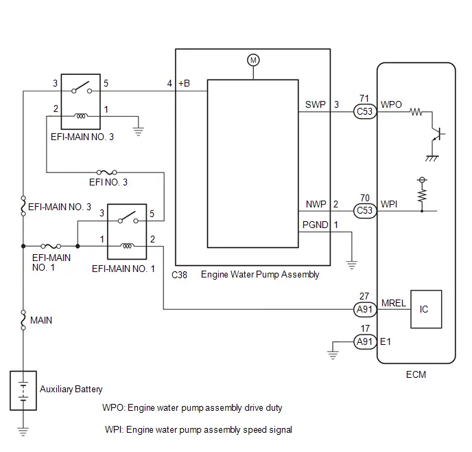
CAUTION / NOTICE / HINT
NOTICE:
-
Toyota Prius Vehicle Control History may be stored in the hybrid vehicle control ECU if the engine is malfunctioning. Certain vehicle condition information is recorded when Vehicle Control History is stored. Reading the vehicle conditions recorded in both the freeze frame data and Vehicle Control History can be useful for troubleshooting.
Click here

(Select Powertrain in Health Check and then check the time stamp data.)
-
If any "Engine Malfunction" Toyota Prius Vehicle Control History item has been stored in the hybrid vehicle control ECU, make sure to clear it. However, as all Vehicle Control History items are cleared simultaneously, if any Vehicle Control History items other than "Engine Malfunction" are stored, make sure to perform any troubleshooting for them before clearing Toyota Prius Vehicle Control History.
Click here

PROCEDURE
| 1. | CHECK TERMINAL VOLTAGE (POWER SOURCE OF ENGINE WATER PUMP ASSEMBLY (WATER INLET HOUSING)) |
Pre-procedure1
(a) Disconnect the engine water pump assembly (water inlet housing) connector.
(b) Turn the ignition switch ON.
Procedure1
(c) Measure the voltage according to the value(s) in the table below.
Standard Voltage:
 Click Location & Routing(C38) Click Connector(C38)
 | Tester Connection | Condition | Specified Condition | Result |
|---|---|---|---|
| C38-3 (SWP) - Body ground | Ignition switch ON | Below 1 V | V |
Post-procedure1
(d) None
| NG |

| GO TO STEP 3 |
|

| 2. | INSPECT ECM (INTERNAL CIRCUIT) |
Pre-procedure1
(a) Disconnect the engine water pump assembly (water inlet housing) connector.
(b) Perform the Active Test using the GTS.
Powertrain > Engine > Active Test| Tester Display |
|---|
| Activate the Electric Water Pump |
Procedure1
(c) Measure the resistance according to the value(s) in the table below.
Standard:
 Click Location & Routing(C38) Click Connector(C38)
 | Tester Connection | Condition | Specified Condition |
|---|---|---|
| C38-3 (SWP) - Body ground | During Active Test | Resistance fluctuates* |
HINT:
*: Using the Active Test, duty control of the transistors in the ECM will be performed. Due to the duty control, resistance of the SWP terminal will be unstable during the Active Test. If the resistance fluctuates while performing the Active Test, it can be determined that the transistor is operating. If the transistor does not operate during the Active Test, the ECM may be malfunctioning.
Post-procedure1
(d) None
| OK |

| REPLACE ENGINE WATER PUMP ASSEMBLY (WATER INLET HOUSING) |
| NG |

| REPLACE ECM |
| 3. | CHECK HARNESS AND CONNECTOR (ENGINE WATER PUMP ASSEMBLY (WATER INLET HOUSING) - ECM) |
Pre-procedure1
(a) Disconnect the engine water pump assembly (water inlet housing) connector.
(b) Disconnect the ECM connector.
Procedure1
(c) Measure the resistance according to the value(s) in the table below.
Standard Resistance:
 Click Location & Routing(C38,C53) Click Connector(C38) Click Connector(C53)
 | Tester Connection | Condition | Specified Condition | Result |
|---|---|---|---|
| C38-3 (SWP) or C53-71 (WPO) - Other terminals | Always | 10 kΩ or higher | kΩ |
Post-procedure1
(d) None
| OK |

| REPLACE ECM |
| NG |

| REPAIR OR REPLACE HARNESS OR CONNECTOR |
Engine Coolant Pump No Signal (P26CA31)
DESCRIPTION
Refer to DTC P26CA12.
Click here

| DTC No. | Detection Item | DTC Detection Condition | Trouble Area | MIL | DTC Output from | Priority | Note |
|---|---|---|---|---|---|---|---|
| P26CA31 | Engine Coolant Pump No Signal | The speed of the engine water pump calculated from the WPI signal is less than 10 rpm (open or short in the WPI circuit) (1 trip detection logic). |
| Comes on | Engine | A | SAE Code: P26CA |
| DTC No. | Data List |
|---|---|
| P26CA31 |
|
MONITOR DESCRIPTION
The ECM receives a frequency signal (WPI) from the engine water pump assembly and calculates the speed of the engine water pump assembly. As the frequency signal (WPI) is 4 Hz when the engine water pump assembly is stopped to enable the ECM to detect an open or short in the signal line, the engine water pump assembly speed will be displayed as approximately 160 rpm even when the pump is stopped. If the engine water pump assembly speed is calculated to be less than 10 rpm, the ECM judges that there is an open or short in the WPI circuit and stores this DTC.
MONITOR STRATEGY
| Required Sensors/Components | Engine water pump assembly |
| Frequency of Operation | Continuous |
CONFIRMATION DRIVING PATTERN
- Clear the DTCs (even if no DTCs are stored, perform the clear DTC procedure).
- Turn the ignition switch off and wait for at least 30 seconds.
- Turn the ignition switch ON [A].
-
Put the engine in Inspection Mode (Maintenance Mode).
Click here

- Start the engine and maintain the engine speed at 2500 rpm or more for at least 40 seconds [B].
- Enter the following menus: Powertrain / Engine / Trouble Codes [C].
-
Read the pending DTCs.
HINT:
- If a pending DTC is output, the system is malfunctioning.
- If a pending DTC is not output, perform the following procedure.
- Enter the following menus: Powertrain / Engine / Utility / All Readiness.
- Input the DTC: P26CA31.
-
Check the DTC judgment result.
HINT:
- If the judgment result is NORMAL, the system is normal.
- If the judgment result is ABNORMAL, the system has a malfunction.
- If the judgment result is INCOMPLETE, perform steps [B] through [C] again.
-
[A] to [C]: Normal judgment procedure.
The normal judgment procedure is used to complete DTC judgment and also used when clearing permanent DTCs.
- When clearing the permanent DTCs, do not disconnect the cable from the auxiliary battery terminal or attempt to clear the DTCs during this procedure, as doing so will clear the universal trip and normal judgment histories.
WIRING DIAGRAM
Refer to DTC P26CA12.
Click here

CAUTION / NOTICE / HINT
NOTICE:
- Inspect the fuses for circuits related to this system before performing the following procedure.
-
Toyota Prius Vehicle Control History may be stored in the hybrid vehicle control ECU if the engine is malfunctioning. Certain vehicle condition information is recorded when Vehicle Control History is stored. Reading the vehicle conditions recorded in both the freeze frame data and Vehicle Control History can be useful for troubleshooting.
Click here

(Select Powertrain in Health Check and then check the time stamp data.)
-
If any "Engine Malfunction" Toyota Prius Vehicle Control History item has been stored in the hybrid vehicle control ECU, make sure to clear it. However, as all Vehicle Control History items are cleared simultaneously, if any Vehicle Control History items other than "Engine Malfunction" are stored, make sure to perform any troubleshooting for them before clearing Toyota Prius Vehicle Control History.
Click here

PROCEDURE
| 1. | CHECK TERMINAL VOLTAGE (POWER SOURCE OF ENGINE WATER PUMP ASSEMBLY (WATER INLET HOUSING)) |
Pre-procedure1
(a) Disconnect the engine water pump assembly (water inlet housing) connector.
(b) Turn the ignition switch ON.
Procedure1
(c) Measure the voltage according to the value(s) in the table below.
Standard Voltage:
 Click Location & Routing(C38) Click Connector(C38)
 | Tester Connection | Condition | Specified Condition | Result |
|---|---|---|---|
| C38-2 (NWP) - Body ground | Ignition switch ON | 11 to 14 V | V |
Post-procedure1
(d) None
| NG |

| GO TO STEP 8 |
|

| 2. | CHECK HARNESS AND CONNECTOR (ENGINE WATER PUMP ASSEMBLY (WATER INLET HOUSING) - BODY GROUND) |
Pre-procedure1
(a) Disconnect the engine water pump assembly (water inlet housing) connector.
Procedure1
(b) Measure the resistance according to the value(s) in the table below.
Standard Resistance:
 Click Location & Routing(C38) Click Connector(C38)
 | Tester Connection | Condition | Specified Condition | Result |
|---|---|---|---|
| C38-1 (PGND) - Body ground | Always | Below 1 Ω | Ω |
Post-procedure1
(c) None
| NG |

| REPAIR OR REPLACE HARNESS OR CONNECTOR |
|

| 3. | CHECK TERMINAL VOLTAGE (POWER SOURCE OF ENGINE WATER PUMP ASSEMBLY (WATER INLET HOUSING)) |
Pre-procedure1
(a) Disconnect the engine water pump assembly (water inlet housing) connector.
(b) Turn the ignition switch ON.
Procedure1
(c) Measure the voltage according to the value(s) in the table below.
Standard Voltage:
 Click Location & Routing(C38) Click Connector(C38)
 | Tester Connection | Condition | Specified Condition | Result |
|---|---|---|---|
| C38-4 ( B) - Body ground | Ignition switch ON | 11 to 14 V | V |
Post-procedure1
(d) None
| OK |

| REPLACE ENGINE WATER PUMP ASSEMBLY (WATER INLET HOUSING) |
|

| 4. | INSPECT EFI-MAIN NO. 3 RELAY |
Click here

| NG |

| REPLACE EFI-MAIN NO. 3 RELAY |
|

| 5. | CHECK HARNESS AND CONNECTOR (POWER SOURCE OF EFI-MAIN NO. 3 RELAY) |
Pre-procedure1
(a) Remove the EFI-MAIN NO. 3 relay from the No. 1 engine room relay block and No. 1 junction block assembly.
Procedure1
(b) Measure the voltage according to the value(s) in the table below.
Standard Voltage:
| Tester Connection | Condition | Specified Condition | Result |
|---|---|---|---|
| 3 (EFI-MAIN NO. 3 relay) - Body ground | Always | 11 to 14 V | V |
Post-procedure1
(c) None
| NG |

| REPAIR OR REPLACE HARNESS OR CONNECTOR (AUXILIARY BATTERY - EFI-MAIN NO. 3 RELAY) |
|

| 6. | CHECK HARNESS AND CONNECTOR (EFI-MAIN NO. 3 RELAY - BODY GROUND) |
Pre-procedure1
(a) Remove the EFI-MAIN NO. 3 relay from the No. 1 engine room relay block and No. 1 junction block assembly.
Procedure1
(b) Measure the resistance according to the value(s) in the table below.
Standard Resistance:
| Tester Connection | Condition | Specified Condition | Result |
|---|---|---|---|
| 1 (EFI-MAIN NO. 3 relay) - Body ground | Always | Below 1 Ω | Ω |
Post-procedure1
(c) None
| NG |

| REPAIR OR REPLACE HARNESS OR CONNECTOR |
|

| 7. | CHECK HARNESS AND CONNECTOR (EFI-MAIN NO. 3 RELAY - ENGINE WATER PUMP ASSEMBLY (WATER INLET HOUSING)) |
Pre-procedure1
(a) Remove the EFI-MAIN NO. 3 relay from the No. 1 engine room relay block and No. 1 junction block assembly.
(b) Disconnect the engine water pump assembly (water inlet housing) connector.
Procedure1
(c) Measure the resistance according to the value(s) in the table below.
Standard Resistance:
 Click Location & Routing(C38) Click Connector(C38)
 | Tester Connection | Condition | Specified Condition | Result |
|---|---|---|---|
| 5 (EFI-MAIN NO. 3 relay) - C38-4 ( B) | Always | Below 1 Ω | Ω |
| 5 (EFI-MAIN NO. 3 relay) or C38-4 ( B) - Body ground and other terminals | Always | 10 kΩ or higher | kΩ |
Post-procedure1
(d) None
| OK |

| REPAIR OR REPLACE HARNESS OR CONNECTOR (EFI-MAIN NO. 1 RELAY - EFI-MAIN NO. 3 RELAY) |
| NG |

| REPAIR OR REPLACE HARNESS OR CONNECTOR |
| 8. | CHECK HARNESS AND CONNECTOR (ENGINE WATER PUMP ASSEMBLY (WATER INLET HOUSING) - ECM) |
Pre-procedure1
(a) Disconnect the engine water pump assembly (water inlet housing) connector.
Procedure1
(b) Disconnect the ECM connector.
(c) Measure the resistance according to the value(s) in the table below.
Standard Resistance:
 Click Location & Routing(C38,C53) Click Connector(C38) Click Connector(C53)
 | Tester Connection | Condition | Specified Condition | Result |
|---|---|---|---|
| C38-2 (NWP) - C53-70 (WPI) | Always | Below 1 Ω | Ω |
| C38-2 (NWP) - C53-70 (WPI) - Body ground and other terminals | Always | 10 kΩ or higher | kΩ |
Post-procedure1
(d) None
| OK |

| REPLACE ECM |
| NG |

| REPAIR OR REPLACE HARNESS OR CONNECTOR |
Engine Coolant Pump Actuator Stuck (P26CB71)
DESCRIPTION
Refer to DTC P26CA12.
Click here

| DTC No. | Detection Item | DTC Detection Condition | Trouble Area | MIL | DTC Output from | Priority | Note |
|---|---|---|---|---|---|---|---|
| P26CB71 | Engine Coolant Pump Actuator Stuck | Even though an operation request signal is being output, the engine water pump assembly does not rotate* (1 trip detection logic). |
| Comes on | Engine | B | SAE Code: P26CB |
*: As the frequency signal (WPI) is 4 Hz when the engine water pump assembly is stopped to enable the ECM to detect an open or short in the signal line, the engine water pump assembly speed will be displayed as approximately 160 rpm even when the pump is stopped. If there is an open in the WPI circuit, the engine water pump speed will be displayed as 0 rpm.
Related Data List| DTC No. | Data List |
|---|---|
| P26CB71 |
|
MONITOR DESCRIPTION
The ECM receives a frequency signal (WPI) from the engine water pump assembly and calculates the speed of the engine water pump assembly. The ECM outputs an operation duty signal (WPO) to steplessly control the speed of the engine water pump assembly. If the duty signal (WPI) indicates that the engine water pump assembly is stopped even though the ECM is outputting an operation duty signal (WPO), the ECM judges that the engine water pump assembly is stuck and stores this DTC.
As the frequency signal (WPI) is 4 Hz when the engine water pump assembly is stopped to enable the ECM to detect an open or short in the signal line, the engine water pump assembly speed will be displayed as approximately 160 rpm even when the pump is stopped.
MONITOR STRATEGY
| Required Sensors/Components | Engine water pump assembly |
| Frequency of Operation | Continuous |
CONFIRMATION DRIVING PATTERN
- Clear the DTCs (even if no DTCs are stored, perform the clear DTC procedure).
- Turn the ignition switch off and wait for at least 30 seconds.
- Turn the ignition switch ON [A].
-
Put the engine in Inspection Mode (Maintenance Mode).
Click here

- Start the engine and maintain the engine speed at 2500 rpm or more for at least 40 seconds [B].
- Enter the following menus: Powertrain / Engine / Trouble Codes [C].
-
Read the pending DTCs.
HINT:
- If a pending DTC is output, the system is malfunctioning.
- If a pending DTC is not output, perform the following procedure.
- Enter the following menus: Powertrain / Engine / Utility / All Readiness.
- Input the DTC: P26CB71.
-
Check the DTC judgment result.
HINT:
- If the judgment result is NORMAL, the system is normal.
- If the judgment result is ABNORMAL, the system has a malfunction.
- If the judgment result is INCOMPLETE, perform steps [B] through [C] again.
-
[A] to [C]: Normal judgment procedure.
The normal judgment procedure is used to complete DTC judgment and also used when clearing permanent DTCs.
- When clearing the permanent DTCs, do not disconnect the cable from the auxiliary battery terminal or attempt to clear the DTCs during this procedure, as doing so will clear the universal trip and normal judgment histories.
WIRING DIAGRAM
Refer to DTC P26CA12.
Click here

CAUTION / NOTICE / HINT
NOTICE:
-
Toyota Prius Vehicle Control History may be stored in the hybrid vehicle control ECU if the engine is malfunctioning. Certain vehicle condition information is recorded when Vehicle Control History is stored. Reading the vehicle conditions recorded in both the freeze frame data and Vehicle Control History can be useful for troubleshooting.
Click here

(Select Powertrain in Health Check and then check the time stamp data.)
-
If any "Engine Malfunction" Toyota Prius Vehicle Control History item has been stored in the hybrid vehicle control ECU, make sure to clear it. However, as all Vehicle Control History items are cleared simultaneously, if any Vehicle Control History items other than "Engine Malfunction" are stored, make sure to perform any troubleshooting for them before clearing Toyota Prius Vehicle Control History.
Click here

HINT:
As the frequency signal (WPI) is 4 Hz when the engine water pump assembly is stopped to enable the ECM to detect an open or short in the signal line, the engine water pump assembly speed will be displayed as approximately 160 rpm even when the pump is stopped.
PROCEDURE
| 1. | CHECK ANY OTHER DTCS OUTPUT (IN ADDITION TO DTC P26CB71) |
(a) Read the DTCs.
Powertrain > Engine > Trouble Codes| Result | Proceed to |
|---|---|
| P26CB71 and other DTCs are output | A |
| P26CB71 is output | B |
| P26CB71 and P26CE37 are output | C |
HINT:
If any DTCs other than P26CB71 are output, troubleshoot those DTCs first.
| A |

| GO TO DTC CHART |
| B |

| GO TO STEP 2 |
|

| 2. | CHECK ENGINE COOLANT LEVEL IN RESERVOIR TANK |
(a) Check that the engine coolant level is between the FULL and LOW lines.
Click here

| Result | Proceed to |
|---|---|
| Engine coolant level is above the LOW line | A |
| Engine coolant level is below the LOW line | B |
| A |

| GO TO STEP 6 |
|

| 3. | CHECK FOR ENGINE COOLANT LEAKS |
(a) Check the areas around the engine and heater for engine coolant leaks.
Click here

HINT:
If the engine oil is cloudy during the engine oil level dipstick check, it means that engine coolant has entered the engine lubrication system.
OK:
No leaks.
| NG |

| GO TO STEP 5 |
|

| 4. | ADD ENGINE COOLANT |
(a) Fill the reservoir tank up to the FULL line with engine coolant.
NOTICE:
Make sure not to add engine coolant when the engine is hot.
HINT:
Click here

| NEXT |

| GO TO STEP 6 |
| 5. | REPAIR OR REPLACE MALFUNCTIONING PARTS, COMPONENT AND AREA |
(a) Repair any engine coolant leaks.
HINT:
Add engine coolant and perform air bleeding after repair.
|

| 6. | PERFORM ACTIVE TEST USING GTS (ACTIVATE THE ELECTRIC WATER PUMP) |
(a) According to the display on the GTS, read the Data List while performing the Active Test.
Powertrain > Engine > Active Test| Active Test Display |
|---|
| Activate the Electric Water Pump |
| Data List Display |
|---|
| Electric Water Pump Speed |
Standard:
| Active Test Operation | Electric Water Pump Speed |
|---|---|
| 3000 rpm | 2000 rpm or higher |
| OK |

| GO TO STEP 8 |
|

| 7. | INSPECT ECM (INTERNAL CIRCUIT) |
Pre-procedure1
(a) Disconnect the engine water pump assembly (water inlet housing) connector.
(b) Perform the Active Test using the GTS.
Powertrain > Engine > Active Test| Tester Display |
|---|
| Activate the Electric Water Pump |
Procedure1
(c) Measure the resistance according to the value(s) in the table below.
Standard:
 Click Location & Routing(C38) Click Connector(C38)
 | Tester Connection | Condition | Specified Condition |
|---|---|---|
| C38-3 (SWP) - Body ground | During Active Test | Resistance fluctuates* |
HINT:
*: Using the Active Test, duty control of the transistors in the ECM will be performed. Due to the duty control, resistance of the SWP terminal will be unstable during the Active Test. If the resistance fluctuates while performing the Active Test, it can be determined that the transistor is operating. If the transistor does not operate during the Active Test, the ECM may be malfunctioning.
Post-procedure1
(d) None
| NG |

| REPLACE ECM |
|

| 8. | REPLACE ENGINE WATER PUMP ASSEMBLY (WATER INLET HOUSING) |
HINT:
-
Click here

- When replacing any cooling system parts, if excessive deposits of rust or scale exist or the concentration of the engine coolant is abnormal, replace the engine coolant.
|

| 9. | CLEAR DTC |
Pre-procedure1
(a) None
Procedure1
(b) Clear the DTCs.
Powertrain > Engine > Clear DTCsPost-procedure1
(c) Turn the ignition switch off and wait for at least 30 seconds.
|

| 10. | CHECK WHETHER DTC OUTPUT RECURS (DTC P26CB71) |
Pre-procedure1
(a) Drive the Toyota Prius vehicle in accordance with the driving pattern described in Confirmation Driving Pattern.
Procedure1
(b) Read the DTCs.
Powertrain > Engine > Trouble CodesHINT:
If no DTC is output, the repair has been successfully completed.
Post-procedure1
(c) None
| NEXT |

| END |
Engine Coolant Pump Overspeed (P26CE37)
DESCRIPTION
Refer to DTC P26CA12.
Click here

| DTC No. | Detection Item | DTC Detection Condition | Trouble Area | MIL | DTC Output from | Priority | Note |
|---|---|---|---|---|---|---|---|
| P26CE37 | Engine Coolant Pump Overspeed | The speed of the engine water pump assembly is a certain value or more when an operation request signal is being output to the engine water pump assembly (1 trip detection logic). |
| Does not come on | Engine | B | SAE Code: P26CE |
| DTC No. | Data List |
|---|---|
| P26CE37 |
|
MONITOR DESCRIPTION
The ECM monitors the speed of the engine water pump assembly. When the speed becomes a certain value or more, the ECM judges that the speed is abnormally high and stores a DTC (The MIL does not illuminate).
MONITOR STRATEGY
| Frequency of Operation | Continuous |
CONFIRMATION DRIVING PATTERN
- Clear the DTCs (even if no DTCs are stored, perform the clear DTC procedure).
- Turn the ignition switch off and wait for at least 30 seconds.
- Turn the ignition switch ON.
-
Put the engine in Inspection Mode (Maintenance Mode).
Click here

- Start the engine and maintain an engine speed of 2500 rpm or more for at least 40 seconds [A].
- Enter the following menus: Powertrain / Engine / Trouble Codes [B].
-
Read the pending DTCs.
HINT:
- If a pending DTC is output, the system is malfunctioning.
- If a pending DTC is not output, perform the following procedure.
- Enter the following menus: Powertrain / Engine / Utility / All Readiness.
- Input the DTC: P26CE37.
-
Check the DTC judgment result.
HINT:
- If the judgment result is NORMAL, the system is normal.
- If the judgment result is ABNORMAL, the system has a malfunction.
- If the judgment result is INCOMPLETE, perform steps [C] through [D].
- Idle the engine for 5 minutes or more [C].
- Enter the following menus: Powertrain / Engine / Trouble Codes [D].
-
Read the pending DTCs.
HINT:
- If a pending DTC is output, the system is malfunctioning.
- If a pending DTC is not output, perform the following procedure.
- Enter the following menus: Powertrain / Engine / Utility / All Readiness.
-
Check the DTC judgment result.
HINT:
- If the judgment result is NORMAL, the system is normal.
- If the judgment result is ABNORMAL, the system has a malfunction.
CAUTION / NOTICE / HINT
NOTICE:
-
Toyota Prius Vehicle Control History may be stored in the hybrid vehicle control ECU if the engine is malfunctioning. Certain vehicle condition information is recorded when Vehicle Control History is stored. Reading the vehicle conditions recorded in both the freeze frame data and Vehicle Control History can be useful for troubleshooting.
Click here

(Select Powertrain in Health Check and then check the time stamp data.)
-
If any "Engine Malfunction" Toyota Prius Vehicle Control History item has been stored in the hybrid vehicle control ECU, make sure to clear it. However, as all Vehicle Control History items are cleared simultaneously, if any Vehicle Control History items other than "Engine Malfunction" are stored, make sure to perform any troubleshooting for them before clearing Toyota Prius Vehicle Control History.
Click here

HINT:
- If the engine is run continuously with a low engine coolant level, DTC P26CE37 may be stored.
- If the engine coolant level is sufficient but DTC P26CE37 is output, confirm with the customer whether engine coolant was added after the Toyota Prius vehicle had been driven with insufficient engine coolant.
- Read Freeze Frame Data using the GTS. The ECM records vehicle and driving condition information as Freeze Frame Data the moment a DTC is stored. When troubleshooting, Freeze Frame Data can help determine if the vehicle was moving or stationary, if the engine was warmed up or not, if the air fuel ratio was lean or rich, and other data from the time the malfunction occurred.
PROCEDURE
| 1. | CHECK ANY OTHER DTCS OUTPUT (IN ADDITION TO DTC P26CE37) |
(a) Read the DTCs.
Powertrain > Engine > Trouble Codes| Result | Proceed to |
|---|---|
| P26CE37 and P26CB71 are output | A |
| P26CE37 and other DTCs are output | B |
| P26CE37 is output | C |
HINT:
- If any DTCs other than P26CE37 are output, troubleshoot those DTCs first.
- If both DTC P26CB71 (pump stuck) and P26CE37 (pump overspeed) are stored, perform troubleshooting for DTC P26CB71 first as the engine coolant pump assembly may be stuck.
| A |

| GO TO DTC P26CB71 |
| B |

| GO TO DTC CHART |
|

| 2. | CHECK ENGINE COOLANT LEVEL IN RESERVOIR TANK |
(a) Check that the engine coolant level is between the FULL and LOW lines.
Click here

| Result | Proceed to |
|---|---|
| Engine coolant level is above the LOW line | A |
| Engine coolant level is below the LOW line | B |
| A |

| GO TO STEP 6 |
|

| 3. | CHECK FOR ENGINE COOLANT LEAKS |
(a) Check the areas around the engine and heater for engine coolant leaks.
Click here

HINT:
If the engine oil is cloudy during the engine oil level dipstick check, it means that engine coolant has entered the engine lubrication system.
OK:
No leaks.
| NG |

| GO TO STEP 5 |
|

| 4. | ADD ENGINE COOLANT |
(a) Fill the reservoir tank up to the FULL line with engine coolant.
NOTICE:
Make sure not to add engine coolant when the engine is hot.
HINT:
Click here

| NEXT |

| GO TO STEP 6 |
| 5. | REPAIR OR REPLACE MALFUNCTIONING PARTS, COMPONENT AND AREA |
(a) Repair any engine coolant leaks.
HINT:
Add engine coolant and perform air bleeding after repair.
|

| 6. | BLEED ENGINE COOLANT |
HINT:
Bleed air from the cooling system.
Click here

|

| 7. | CLEAR DTC |
Pre-procedure1
(a) None
Procedure1
(b) Clear the DTCs.
Powertrain > Engine > Clear DTCsPost-procedure1
(c) Turn the ignition switch off and wait for at least 30 seconds.
|

| 8. | CHECK WHETHER DTC OUTPUT RECURS (DTC P26CE37) |
Pre-procedure1
(a) Drive the Toyota Prius vehicle in accordance with the driving pattern described in Confirmation Driving Pattern.
Procedure1
(b) Read the DTCs.
Powertrain > Engine > Trouble Codes| Result | Proceed to |
|---|---|
| DTCs are not output | A |
| P26CB71 is output | B |
| P26CE37 is output | C |
Post-procedure1
(c) None
| A |

| END |
| B |

| GO TO DTC P26CB71 |
|

| 9. | BLEED ENGINE COOLANT |
(a) Bleed air from the cooling system.
HINT:
Click here

|

| 10. | CLEAR DTC |
Pre-procedure1
(a) None
Procedure1
(b) Clear the DTCs.
Powertrain > Engine > Clear DTCsPost-procedure1
(c) Turn the ignition switch off and wait for at least 30 seconds.
|

| 11. | CHECK WHETHER DTC OUTPUT RECURS (DTC P26CE37) |
Pre-procedure1
(a) Drive the Toyota Prius vehicle in accordance with the driving pattern described in Confirmation Driving Pattern.
Procedure1
(b) Read the DTCs.
Powertrain > Engine > Trouble Codes| Result | Proceed to |
|---|---|
| DTCs are not output | A |
| P26CE37 is output | B |
Post-procedure1
(c) None
| A |

| END |
|

| 12. | REPLACE ENGINE WATER PUMP ASSEMBLY (WATER INLET HOUSING) |
HINT:
-
Click here

- When replacing any cooling system parts, if excessive deposits of rust or scale exist or the concentration of the engine coolant is abnormal, replace the engine coolant.
|

| 13. | CLEAR DTC |
Pre-procedure1
(a) None
Procedure1
(b) Clear the DTCs.
Powertrain > Engine > Clear DTCsPost-procedure1
(c) Turn the ignition switch off and wait for at least 30 seconds.
|

| 14. | CHECK WHETHER DTC OUTPUT RECURS (DTC P26CE37) |
Pre-procedure1
(a) Drive the Toyota Prius vehicle in accordance with the driving pattern described in Confirmation Driving Pattern.
Procedure1
(b) Read the DTCs.
Powertrain > Engine > Trouble CodesHINT:
If no DTC is output, the repair has been successfully completed.
Post-procedure1
(c) None
| NEXT |

| END |
O2 Sensor Circuit Range/Performance Bank 1 Sensor 1 Signal Rate of Change Below Threshold (P2A0026)
DESCRIPTION
Refer to DTC P003012.
Click here

| DTC No. | Detection Item | DTC Detection Condition | Trouble Area | MIL | DTC Output from | Priority | Note |
|---|---|---|---|---|---|---|---|
| P2A0026 | O2 Sensor Circuit Range/Performance Bank 1 Sensor 1 Signal Rate of Change Below Threshold | The calculated value for the air fuel ratio sensor response rate deterioration level is less than the threshold (2 trip detection logic). |
| Comes on | Engine | B | SAE Code: P2A00 |
MONITOR DESCRIPTION
After the engine is warmed up, the ECM performs air fuel ratio feedback control to maintain the air fuel ratio at the stoichiometric level. In addition, active air fuel ratio control is performed for approximately 30 seconds after preconditions are met in order to measure the air fuel ratio sensor response rate. During active air fuel ratio control, the ECM forcibly increases and decreases the injection volume by a certain amount, based on the stoichiometric air fuel ratio learned during normal air fuel ratio control, and measures the air fuel ratio sensor response rate. The ECM receives a signal from the air fuel ratio sensor while performing active air fuel ratio control and uses it to calculate the air fuel ratio sensor response rate deterioration level.
If the value for the air fuel ratio sensor response rate deterioration level is less than the threshold, the ECM interprets this as a malfunction and stores this DTC.

MONITOR STRATEGY
| Required Sensors/Components | Air fuel ratio sensor |
| Frequency of Operation | Once per driving cycle |
TYPICAL ENABLING CONDITIONS
| Active air fuel ratio control | Performing |
| Active air fuel ratio control performed when following conditions met | - |
| Engine coolant temperature | 75°C (167°F) or higher |
| Idling | Off |
| Engine speed | 1000 rpm or more, and less than 4000 rpm |
| Air fuel ratio sensor status | Activated |
| Engine load | 10% or higher, and less than 70% |
| Catalyst monitor | Not yet |
| Mass air flow | 5 gm/sec or more, and less than 14 gm/sec |
CONFIRMATION DRIVING PATTERN
HINT:
Performing this confirmation driving pattern will activate the air fuel ratio sensor response monitor.

- Clear the DTCs (even if no DTCs are stored, perform the clear DTC procedure).
- Turn the ignition switch off and wait for at least 30 seconds.
- Turn the ignition switch ON .
-
Put the engine in Inspection Mode (Maintenance Mode).
Click here

- Start the engine and warm it up until the engine coolant temperature is 75°C (167°F) or higher [A].
-
With the engine running, drive the Toyota Prius vehicle at a speed between 60 and 100 km/h (37 and 62 mph) for 10 minutes or more in a city area [B].
CAUTION:
When performing the confirmation driving pattern, obey all speed limits and traffic laws.
HINT:
If the engine stops, further depress the accelerator pedal to restart the engine.
- Enter the following menus: Powertrain / Engine / Trouble Codes [C].
-
Read the pending DTCs.
HINT:
- If a pending DTC is output, the system is malfunctioning.
- If a pending DTC is not output, perform the following procedure.
- Enter the following menus: Powertrain / Engine / Utility / All Readiness.
- Input the DTC: P2A0026.
-
Check the DTC judgment result.
HINT:
- If the judgment result is NORMAL, the system is normal.
- If the judgment result is ABNORMAL, the system is malfunctioning.
- If the judgment result is INCOMPLETE and no pending DTC is output, perform the following procedure.
-
With the engine running, drive the Toyota Prius vehicle at a speed between 75 and 100 km/h (47 and 62 mph) for 10 minutes [D].
CAUTION:
When performing the confirmation driving pattern, obey all speed limits and traffic laws.
HINT:
If the engine stops, further depress the accelerator pedal to restart the engine.
- Enter the following menus: Powertrain / Engine / Trouble Codes [E].
-
Read the pending DTCs.
HINT:
- If a pending DTC is output, the system is malfunctioning.
- If a pending DTC is not output, perform the following procedure.
- Enter the following menus: Powertrain / Engine / Utility / All Readiness.
- Input the DTC: P2A0026.
-
Check the DTC judgment result.
HINT:
- If the judgment result is NORMAL, the system is normal.
- If the judgment result is ABNORMAL, the system is malfunctioning.
- If the judgment result is INCOMPLETE, drive the Toyota Prius vehicle again under an increased load and then recheck the judgment result.
WIRING DIAGRAM
Refer to DTC P003012.
Click here

CAUTION / NOTICE / HINT
NOTICE:
- Inspect the fuses for circuits related to this system before performing the following procedure.
-
Toyota Prius Vehicle Control History may be stored in the hybrid vehicle control ECU assembly if the engine is malfunctioning. Certain vehicle condition information is recorded when Vehicle Control History is stored. Reading the vehicle conditions recorded in both the freeze frame data and Vehicle Control History can be useful for troubleshooting.
Click here

(Select Powertrain in Health Check and then check the time stamp data.)
-
If any "Engine Malfunction" Toyota Prius Vehicle Control History item has been stored in the hybrid vehicle control ECU assembly, make sure to clear it. However, as all Vehicle Control History items are cleared simultaneously, if any Vehicle Control History items other than "Engine Malfunction" are stored, make sure to perform any troubleshooting for them before clearing Toyota Prius Vehicle Control History.
Click here

HINT:
- DTC P2A0026 may be also stored when the air fuel ratio is stuck at rich or lean.
- A low air fuel ratio sensor voltage could be caused by a rich air fuel mixture. Check for conditions that would cause the engine to run rich.
- A high air fuel ratio sensor voltage could be caused by a lean air fuel mixture. Check for conditions that would cause the engine to run lean.
- Sensor 1 refers to the sensor closest to the engine assembly.
- Sensor 2 refers to the sensor farthest away from the engine assembly.
PROCEDURE
| 1. | CHECK ANY OTHER DTCS OUTPUT (IN ADDITION TO DTC P2A0026) |
(a) Read the DTCs.
Powertrain > Engine > Trouble Codes| Result | Proceed to |
|---|---|
| P2A0026 and other DTCs are output | A |
| P2A0026 is output | B |
HINT:
If any DTCs other than P2A0026 are output, troubleshoot those DTCs first.
| A |

| GO TO DTC CHART |
|

| 2. | PERFORM ACTIVE TEST USING GTS (CONTROL THE INJECTION VOLUME FOR A/F SENSOR) |
Pre-procedure1
(a) Put the engine in Inspection Mode (Maintenance Mode).
Powertrain > Hybrid Control > Utility| Tester Display |
|---|
| Inspection Mode |
(b) Start the engine and warm it up until the engine coolant temperature is 75°C (167°F) or higher.
Powertrain > Engine > Data List| Tester Display |
|---|
| Coolant Temperature |
(c) Idle the engine for 5 minutes or more with park (P) selected.
Procedure1
(d) Change the fuel injection volume using the GTS, and monitor the output voltage of the air fuel ratio sensor (A/F (O2) Sensor Current B1S1) and heated oxygen sensor (O2 Sensor Voltage B1S2) displayed on the GTS.
Powertrain > Engine > Active Test| Active Test Display |
|---|
| Control the Injection Volume for A/F Sensor |
| Data List Display |
|---|
| A/F (O2) Sensor Current B1S1 |
| O2 Sensor Voltage B1S2 |
HINT:
- The Control the Injection Volume for A/F Sensor operation lowers the fuel injection volume by 12.5% or increases the injection volume by 12.5%.
- The air fuel ratio sensor is displayed as A/F (O2) Sensor Current B1S1, and the heated oxygen sensor is displayed as O2 Sensor Voltage B1S2 on the GTS.
- The air fuel ratio sensor has an output delay of a few seconds and the heated oxygen sensor has a maximum output delay of approximately 20 seconds.
- If the sensor output voltage does not change (almost no reaction) while performing the Active Test, the sensor may be malfunctioning.
Standard:
| GTS Display (Sensor) | Injection Volume | Status | Voltage |
|---|---|---|---|
| A/F (O2) Sensor Current B1S1 (Air fuel ratio) | 12.5% | Rich | Below -0.075 mA |
| -12.5% | Lean | Higher than 0.037 mA | |
| O2 Sensor Voltage B1S2 (Heated oxygen) | 12.5% | Rich | Higher than 0.55 V |
| -12.5% | Lean | Below 0.4 V |
| Status of A/F (O2) Sensor Current B1S1 | Status of O2 Sensor Voltage B1S2 | Air Fuel Ratio Condition and Air Fuel Ratio Sensor Condition | Proceed to |
|---|---|---|---|
| Lean/Rich | Lean/Rich | Normal | A |
| Lean | Lean | Actual air fuel ratio lean | B |
| Rich | Rich | Actual air fuel ratio rich | |
| Lean | Lean/Rich | Air fuel ratio sensor malfunction | C |
| Rich | Lean/Rich | Air fuel ratio sensor malfunction |
- Lean: While performing the Active Test "Control the Injection Volume for A/F Sensor", the air fuel ratio sensor output voltage (A/F (O2) Sensor Current B1S1) is consistently higher than 0.037 mA, and the heated oxygen sensor output voltage (O2 Sensor Voltage B1S2) is consistently below 0.4 V.
- Rich: While performing the Active Test "Control the Injection Volume for A/F Sensor", the air fuel ratio sensor output voltage (A/F (O2) Sensor Current B1S1) is consistently below -0.075 mA, and the heated oxygen sensor output voltage (O2 Sensor Voltage B1S2) is consistently higher than 0.55 V.
-
Lean/Rich: While performing the Active Test "Control the Injection Volume for A/F Sensor", the output voltage of the fuel ratio sensor (A/F (O2) Sensor Current B1S1) or heated oxygen sensor (O2 Sensor Voltage B1S2) alternates correctly.
HINT:
Refer to "Data List / Active Test" [A/F (O2) Sensor Current B1S1 and O2 Sensor Voltage B1S2].
Click here

Post-procedure1
(e) None
| B |

| GO TO STEP 7 |
| C |

| GO TO STEP 15 |
|

| 3. | CLEAR DTC |
Pre-procedure1
(a) None
Procedure1
(b) Clear the DTCs.
Powertrain > Engine > Clear DTCsPost-procedure1
(c) Turn the ignition switch off and wait for at least 30 seconds.
|

| 4. | CHECK WHETHER DTC OUTPUT RECURS (DTC P2A0026) |
Pre-procedure1
(a) Drive the Toyota Prius vehicle in accordance with the driving pattern described in Confirmation Driving Pattern.
Procedure1
(b) Check the DTC judgment result.
Powertrain > Engine > Utility| Tester Display |
|---|
| All Readiness |
(c) Input the DTC: P2A0026.
| Result | Proceed to |
|---|---|
| NORMAL (DTC is not output) | A |
| ABNORMAL (DTC P2A0026 is output) | B |
Post-procedure1
(d) None
| A |

| END |
|

| 5. | PERFORM ACTIVE TEST USING GTS (CONTROL THE EGR STEP POSITION) |
Pre-procedure1
(a) Put the engine in Inspection Mode (Maintenance Mode).
Powertrain > Hybrid Control > Utility| Tester Display |
|---|
| Inspection Mode |
(b) Start the engine and warm it up until the engine coolant temperature is 75°C (167°F) or higher.
HINT:
The A/C switch and all accessories should be off.
Powertrain > Engine > Data List| Tester Display |
|---|
| Coolant Temperature |
Procedure1
(c) Confirm that the value of Data List item Engine Independent is "Operate" then check the value of Intake Manifold Absolute Pressure while performing the Active Test.
Powertrain > Engine > Active Test| Active Test Display |
|---|
| Control the EGR Step Position |
| Data List Display |
|---|
| Intake Manifold Absolute Pressure |
| Engine Independent |
NOTICE:
- Do not leave the EGR valve open for 10 seconds or more during the Active Test.
- Be sure to return the EGR valve to step 0 when the Active Test is completed.
- Do not open the EGR valve 30 steps or more during the Active Test.
OK:
The value of Intake Manifold Absolute Pressure changes in response to the EGR step position when the value of Engine Independent is "Operate".
Standard:
| - | Control the EGR Step Position (Active Test) | |
|---|---|---|
| 0 Steps | 0 to 30 Steps | |
| Intake Manifold Absolute Pressure (Data List) | (EGR valve is fully closed) | Intake Manifold Absolute Pressure value is at least 10 kPa (75 mmHg) higher than when EGR valve is fully closed |
HINT:
- If the value of Data List item Engine Independent is "Not Opr" when the engine is idling, charge control is being performed. Perform the Active Test after charge control is complete ("Operate" is displayed).
- While performing the Active Test, if the increase in the value of Intake Manifold Absolute Pressure is small, the EGR valve assembly may be malfunctioning.
- Even if the EGR valve assembly is malfunctioning, rough idling or an increase in the value of Intake Manifold Absolute Pressure may occur while performing the Active Test. However, the amount that the value of Intake Manifold Absolute Pressure increases will be smaller than normal.
| Result | Proceed to |
|---|---|
| Intake Manifold Absolute Pressure value is at least 10 kPa (75 mmHg) higher than when EGR valve is fully closed | A |
| None of the above conditions are met | B |
Post-procedure1
(d) None
| A |

| GO TO STEP 15 |
|

| 6. | INSPECT EGR VALVE ASSEMBLY |
Pre-procedure1
(a) Remove the EGR valve assembly.
HINT:
Click here

Procedure1
(b) Check if the EGR valve is stuck open.
OK:
EGR valve is tightly closed.
Post-procedure1
(c) None
| OK |

| GO TO STEP 15 |
| NG |

| REPLACE EGR VALVE ASSEMBLY |
| 7. | INSPECT AIR FUEL RATIO SENSOR (HEATER RESISTANCE) |
Click here

| NG |

| REPLACE AIR FUEL RATIO SENSOR |
|

| 8. | CHECK INTAKE SYSTEM |
(a) Check the intake system for vacuum leaks.
Click here

OK:
No leaks from the intake system.
HINT:
Perform "Inspection After Repair" after repairing or replacing the intake system.
Click here

| NG |

| REPAIR OR REPLACE INTAKE SYSTEM |
|

| 9. | CHECK FOR EXHAUST GAS LEAK |
(a) Check for exhaust gas leaks.
OK:
No gas leaks in exhaust system.
HINT:
Perform "Inspection After Repair" after repairing or replacing the exhaust system.
Click here

| NG |

| REPAIR OR REPLACE EXHAUST SYSTEM |
|

| 10. | PERFORM ACTIVE TEST USING GTS (CONTROL THE EGR STEP POSITION) |
Pre-procedure1
(a) Put the engine in Inspection Mode (Maintenance Mode).
Powertrain > Hybrid Control > Utility| Tester Display |
|---|
| Inspection Mode |
(b) Start the engine and warm it up until the engine coolant temperature is 75°C (167°F) or higher.
Powertrain > Engine > Data List| Tester Display |
|---|
| Coolant Temperature |
HINT:
The A/C switch and all accessories should be off.
Procedure1
(c) Confirm that the value of Data List item Engine Independent is "Operate" then check the value of Intake Manifold Absolute Pressure while performing the Active Test.
Powertrain > Engine > Active Test| Active Test Display |
|---|
| Control the EGR Step Position |
| Data List Display |
|---|
| Intake Manifold Absolute Pressure |
| Engine Independent |
NOTICE:
- Do not leave the EGR valve open for 10 seconds or more during the Active Test.
- Be sure to return the EGR valve to step 0 when the Active Test is completed.
- Do not open the EGR valve 30 steps or more during the Active Test.
OK:
The value of Intake Manifold Absolute Pressure changes in response to the EGR step position when the value of Engine Independent is "Operate".
Standard:
| - | Control the EGR Step Position (Active Test) | |
|---|---|---|
| 0 Steps | 0 to 30 Steps | |
| Intake Manifold Absolute Pressure (Data List) | (EGR valve is fully closed) | Intake Manifold Absolute Pressure value is at least 10 kPa (75 mmHg) higher than when EGR valve is fully closed |
HINT:
- If the value of Data List item Engine Independent is "Not Opr" when the engine is idling, charge control is being performed. Perform the Active Test after charge control is complete ("Operate" is displayed).
- While performing the Active Test, if the increase in the value of Intake Manifold Absolute Pressure is small, the EGR valve assembly may be malfunctioning.
- Even if the EGR valve assembly is malfunctioning, rough idling or an increase in the value of Intake Manifold Absolute Pressure may occur while performing the Active Test. However, the amount that the value of Intake Manifold Absolute Pressure increases will be smaller than normal.
| Result | Proceed to |
|---|---|
| Intake Manifold Absolute Pressure value is at least 10 kPa (75 mmHg) higher than when EGR valve is fully closed | A |
| None of the above conditions are met | B |
Post-procedure1
(d) None
| A |

| GO TO STEP 12 |
|

| 11. | INSPECT EGR VALVE ASSEMBLY |
Pre-procedure1
(a) Remove the EGR valve assembly.
HINT:
Click here

Procedure1
(b) Check if the EGR valve is stuck open.
OK:
EGR valve is tightly closed.
Post-procedure1
(c) None
| NG |

| REPLACE EGR VALVE ASSEMBLY |
|

| 12. | CHECK FUEL PRESSURE |
Click here

| NG |

| GO TO STEP 14 |
|

| 13. | INSPECT FUEL INJECTOR ASSEMBLY |
Click here

| OK |

| GO TO STEP 15 |
| NG |

| REPLACE FUEL INJECTOR ASSEMBLY |
| 14. | INSPECT FUEL PUMP |
Click here

| OK |

| REPAIR OR REPLACE FUEL LINE |
| NG |

| REPLACE FUEL PUMP |
| 15. | REPLACE AIR FUEL RATIO SENSOR |
HINT:
Click here

|

| 16. | CLEAR DTC |
Pre-procedure1
(a) None
Procedure1
(b) Clear the DTCs.
Powertrain > Engine > Clear DTCsPost-procedure1
(c) Turn the ignition switch off and wait for at least 30 seconds.
|

| 17. | CHECK WHETHER DTC OUTPUT RECURS (DTC P2A0026) |
Pre-procedure1
(a) Drive the Toyota Prius vehicle in accordance with the driving pattern described in Confirmation Driving Pattern.
Procedure1
(b) Check the DTC judgment result.
Powertrain > Engine > Utility| Tester Display |
|---|
| All Readiness |
(c) Input the DTC: P2A0026.
| Result | Proceed to |
|---|---|
| NORMAL (DTC is not output) | A |
| ABNORMAL (DTC P2A0026 is output) | B |
Post-procedure1
(d) None
| A |

| END |
| B |

| REPLACE ECM |
Poor Engine Power (P319000,P319100)
DESCRIPTION
The ECM receives signals from the hybrid vehicle control ECU such as the requested engine torque, target engine speed and engine cranking status, and controls the engine output based on the target engine speed and requested torque.
| DTC No. | Detection Item | DTC Detection Condition | Trouble Area | MIL | DTC Output from | Priority | Note |
|---|---|---|---|---|---|---|---|
| P319000 | Poor Engine Power | When all of the following conditions are met (1 trip detection logic):
|
| Comes on | Engine | B | SAE Code: P3190 |
| P319100 | Engine does not Start | When all of the following conditions are met (1 trip detection logic):
|
| Comes on | Engine | B | SAE Code: P3191 |
MONITOR DESCRIPTION
- The ECM receives signals such as requested engine torque, target engine speed and engine cranking status from the hybrid Toyota Prius vehicle control ECU.
- The ECM controls engine start and stop and the throttle valve angle based on the signals received from the hybrid vehicle control ECU.
- The ECM receives the actual engine torque calculated by the hybrid vehicle control ECU based on the generator torque.
-
When the actual engine torque is less than 20% of the requested engine torque*, the ECM judges that the engine output is abnormal and stores DTC P319000.
(The engine may not have started in the above situation.)
- *: Requested torque = Requested Engine Torque (kW) / HV Target Engine Speed (rpm) x 9549
-
If the ECM does not detect engine start torque (actual engine torque) even though it has received an engine start request and started the engine, it stores DTC P319100.
HINT:
-
When DTCs P319000, P319100 and P319300 are output, the engine may be stopped due to the engine condition.
At this time, after adding fuel or performing repairs, clear the DTCs. Then turn the ignition switch off to return to the normal condition.
- When this DTC is output and the engine is stopped, the HV battery cannot be charged since the Toyota Prius vehicle is driven with the motor only. If the vehicle continues to be driven under this condition, the HV battery will be come depleted and the ignition switch will not be able to be turned on (READY).
-
When DTC P319000 or P319100 is stored, the engine torque has dropped by 80% or the engine cannot be started. If any DTCs that indicate malfunctioning of engine related parts are stored at the same time, repair the malfunctioning parts first.
Relevant Data List Items:
-
If engine knock is detected due to mechanical noise or a knock control sensor being loose, the ignition timing (Knock F/B Value, Knock Correct Learn Value) may be excessively retarded and DTC P319000 may be stored.
ECM (Powertrain / Engine / Data List)
HV Target Engine Speed
Engine Speed
Requested Engine Torque
Actual Engine Torque
Throttle Position Command
Throttle Position Sensor No.1 Voltage
Calculate Load
Coolant Temperature
Short FT B1S1
Long FT B1S1
Target EGR Valve Position No.1
Ignition Timing Cylinder #1
Knock F/B Value
Knock Correct Learn Value
-
-
Hybrid Toyota Prius Vehicle Control ECU (Powertrain / Hybrid Control / Data List)
Target Engine Revolution
Engine Speed
Target Engine Power
Coolant Temperature
Engine Idling Request
-
-
-
-
When DTCs P319000, P319100 and P319300 are output, the engine may be stopped due to the engine condition.
MONITOR STRATEGY
| Frequency of Operation | Continuous |
CONFIRMATION DRIVING PATTERN
NOTICE:
If the MIL or a warning light illuminates, immediately end the confirmation driving pattern. If DTCs P319000, P319100 and P319300 are output and the engine is stopped, the HV battery will no longer be chargeable and the distance that the Toyota Prius vehicle can be driven will be limited.
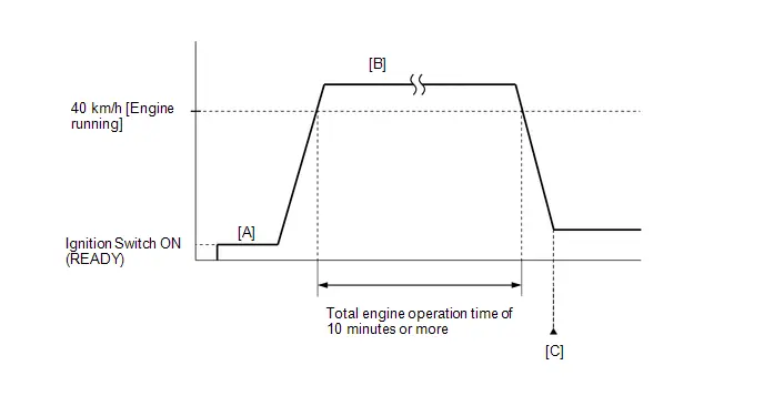
- Apply the parking brake firmly.
- Clear the DTCs (even if no DTCs are stored, perform the clear DTC procedure).
- Turn the ignition switch off and wait for at least 30 seconds.
- Turn the ignition switch ON (READY).
-
Fully depress the accelerator pedal for 10 seconds with the Toyota Prius vehicle stopped, park (P) selected and the brake pedal depressed [A].
NOTICE:
As soon as the engine starts, release the accelerator pedal.
- Release the parking brake.
-
Drive the vehicle at an average of approximately 40 km/h (25 mph) or more until the total engine operation time is 10 minutes or more [B].
CAUTION:
When performing the confirmation driving pattern, obey all speed limits and traffic laws.
HINT:
- It is not necessary to maintain the Toyota Prius vehicle speed at 40 km/h (25 mph) throughout the road test.
- If the engine stops, further depress the accelerator pedal to restart the engine.
- Enter the following menus: Powertrain / Engine / Trouble Codes [C].
-
Read the pending DTCs.
HINT:
- If a pending DTC is output, the system is malfunctioning.
- If a pending DTC is not output, perform the following procedure.
- Enter the following menus: Powertrain / Engine / Utility / All Readiness.
- Input the DTC: P319000 or P319100.
-
Check the DTC judgment result.
HINT:
- If the judgment result is NORMAL, the system is normal.
- If the judgment result is ABNORMAL, the system is malfunctioning.
- If the judgment result is INCOMPLETE, perform the Confirmation Driving Pattern and check the DTC judgment result again.
CAUTION / NOTICE / HINT
NOTICE:
-
Toyota Prius Vehicle Control History may be stored in the hybrid vehicle control ECU if the engine is malfunctioning. Certain vehicle condition information is recorded when Vehicle Control History is stored. Reading the vehicle conditions recorded in both the freeze frame data and Vehicle Control History can be useful for troubleshooting.
Click here

(Select Powertrain in Health Check and then check the time stamp data.)
-
If any "Engine Malfunction" Toyota Prius Vehicle Control History item has been stored in the hybrid vehicle control ECU, make sure to clear it. However, as all Vehicle Control History items are cleared simultaneously, if any Vehicle Control History items other than "Engine Malfunction" are stored, make sure to perform any troubleshooting for them before clearing Toyota Prius Vehicle Control History.
Click here

HINT:
- Performing this diagnosis procedure repeatedly for symptom confirmation may cause the SOC to drop, preventing the system from entering the READY-on state. In this case, use the THS charger to charge the HV battery.
- Cranking the engine once causes the SOC to drop approximately 1%.
- Charging the HV battery once (10 minutes) using the THS charger restores the SOC approximately 2%.
- Charging the HV battery using the THS charger takes approximately 10 minutes when the HV battery temperature is 25°C (77°F) or approximately 30 minutes when the HV battery temperature is 0°C (32°F).
- The THS charger is a supplemental charging device that charges the HV battery enough to enable the engine to start (the Toyota Prius vehicle can enter the READY-on state).
PROCEDURE
| 1. | CHECK ANY OTHER DTCS OUTPUT (IN ADDITION TO DTC P319000, P319100 AND/OR P319300) |
(a) Check for DTCs and freeze frame data and write them down.
Powertrain > Engine > Trouble Codes| Result | Proceed to |
|---|---|
| P319000, P319100 or P319300 and other DTCs are output | A |
| P319300 is output | B |
| P319000 or P319100 is output | C |
HINT:
If any SFI system DTCs other than DTC P319000, P319100 or P319300 are output, perform troubleshooting for those DTCs first.
| A |

| GO TO DTC CHART |
| B |

| GO TO DTC P319300 |
|

| 2. | CHECK SHORTAGE OF FUEL |
(a) Check the amount of fuel remaining.
OK:
There is enough fuel.
HINT:
- DTCs P319000, P319100 and/or P319300 may be output if the Toyota Prius vehicle ran out of fuel in the past.
- If not enough fuel is added, DTC P319000, P319100 or P319300 may be output again. If the engine cannot be started because the vehicle is out of fuel, add fuel until the fuel level warning light turns off.
| NG |

| REFILL FUEL |
|

| 3. | CLEAR DTC |
Pre-procedure1
(a) None
Procedure1
(b) Clear the DTCs.
Powertrain > Engine > Clear DTCsPost-procedure1
(c) Turn the ignition switch off and wait for at least 30 seconds.
|

| 4. | CHECK INTAKE SYSTEM |
(a) Check the intake system for vacuum leaks.
Click here

OK:
No leaks from intake system.
HINT:
Perform "Inspection After Repair" after repairing or replacing the intake system.
Click here

| NG |

| REPAIR OR REPLACE INTAKE SYSTEM |
|

| 5. | CHECK FOR UNUSUAL NOISE OR VIBRATION WHEN STARTING ENGINE OR REVVING |
OK:
Unusual noise and vibration do not occur.
| NG |

| REPAIR OR REPLACE MALFUNCTIONING PARTS |
|

| 6. | CHECK FUEL PRESSURE |
Click here

| NG |

| CHECK FUEL PUMP CONTROL CIRCUIT |
|

| 7. | INSPECT THROTTLE BODY ASSEMBLY |
Click here

| NG |

| REPLACE THROTTLE BODY ASSEMBLY |
|

| 8. | INSPECT MASS AIR FLOW METER SUB-ASSEMBLY |
(a) Inspect the mass air flow meter sub-assembly, referring to On-Toyota Prius vehicle Inspection for Mass Air Flow Meter.
Click here

(b) Inspect the mass air flow meter sub-assembly, referring to Inspection for Mass Air Flow Meter.
Click here

| NG |

| REPLACE MASS AIR FLOW METER SUB-ASSEMBLY |
|

| 9. | INSPECT ENGINE COOLANT TEMPERATURE SENSOR |
Click here

| NG |

| REPLACE ENGINE COOLANT TEMPERATURE SENSOR |
|

| 10. | REPLACE CRANKSHAFT POSITION SENSOR |
HINT:
Click here

|

| 11. | CLEAR DTC |
Pre-procedure1
(a) None
Procedure1
(b) Clear the DTCs.
Powertrain > Engine > Clear DTCsPost-procedure1
(c) Turn the ignition switch off and wait for at least 30 seconds.
|

| 12. | CHECK WHETHER DTC OUTPUT RECURS (DTC P319000 OR P319100) |
Pre-procedure1
(a) Drive the Toyota Prius vehicle in accordance with the driving pattern described in Confirmation Driving Pattern.
Procedure1
(b) Read the DTCs.
Powertrain > Engine > Trouble Codes| Result | Proceed to |
|---|---|
| DTCs are not output | A |
| P319000 or P319100 is output | B |
Post-procedure1
(c) None
| A |

| END |
|

| 13. | PERFORM ACTIVE TEST USING GTS (CONTROL THE EGR STEP POSITION) |
Pre-procedure1
(a) Put the engine in Inspection Mode (Maintenance Mode).
Powertrain > Hybrid Control > Utility| Tester Display |
|---|
| Inspection Mode |
(b) Start the engine and warm it up until the engine coolant temperature is 75°C (167°F) or higher.
Powertrain > Engine > Data List| Tester Display |
|---|
| Coolant Temperature |
HINT:
The A/C switch and all accessories should be off.
Procedure1
(c) Confirm that the value of Data List item Engine Independent is "Operate" then check the value of Intake Manifold Absolute Pressure while performing the Active Test.
Powertrain > Engine > Active Test| Active Test Display |
|---|
| Control the EGR Step Position |
| Data List Display |
|---|
| Intake Manifold Absolute Pressure |
| Engine Independent |
NOTICE:
- Do not leave the EGR valve open for 10 seconds or more during the Active Test.
- Be sure to return the EGR valve to step 0 when the Active Test is completed.
- Do not open the EGR valve 30 steps or more during the Active Test.
OK:
The value of Intake Manifold Absolute Pressure changes in response to the EGR step position when the value of Engine Independent is "Operate".
Standard:
| - | Control the EGR Step Position (Active Test) | |
|---|---|---|
| 0 Steps | 0 to 30 Steps | |
| Intake Manifold Absolute Pressure (Data List) | (EGR valve is fully closed) | Intake Manifold Absolute Pressure value is at least 10 kPa (1.45 psi) higher than when EGR valve is fully closed |
HINT:
- If the value of Data List item Engine Independent is "Not Opr" when the engine is idling, charge control is being performed. Perform the Active Test after charge control is complete ("Operate" is displayed).
- While performing the Active Test, if the increase in the value of Intake Manifold Absolute Pressure is small, the EGR valve assembly may be malfunctioning.
- Even if the EGR valve assembly is malfunctioning, rough idling or an increase in the value of Intake Manifold Absolute Pressure may occur while performing the Active Test. However, the amount that the value of Intake Manifold Absolute Pressure increases will be smaller than normal.
- If the Active Test cannot be performed due to a malfunction such as the engine not starting, perform the EGR valve assembly inspection the following step.
| Result | Proceed to |
|---|---|
| Intake Manifold Absolute Pressure value is at least 10 kPa (1.45 psi) higher than when EGR valve is fully closed | A |
| None of the above conditions are met | B |
Post-procedure1
(d) None
| A |

| GO TO STEP 15 |
|

| 14. | INSPECT EGR VALVE ASSEMBLY |
Pre-procedure1
(a) Remove the EGR valve assembly.
HINT:
Click here

Procedure1
(b) Check if the EGR valve is stuck open.
OK:
EGR valve is tightly closed.
Post-procedure1
(c) None
| NG |

| REPLACE EGR VALVE ASSEMBLY |
|

| 15. | REPLACE CAMSHAFT POSITION SENSOR |
HINT:
Click here

|

| 16. | CLEAR DTC |
Pre-procedure1
(a) None
Procedure1
(b) Clear the DTCs.
Powertrain > Engine > Clear DTCsPost-procedure1
(c) Turn the ignition switch off and wait for at least 30 seconds.
|

| 17. | CHECK WHETHER DTC OUTPUT RECURS (DTC P319000 OR P319100) |
Pre-procedure1
(a) Drive the Toyota Prius vehicle in accordance with the driving pattern described in Confirmation Driving Pattern.
Procedure1
(b) Read the DTCs.
Powertrain > Engine > Trouble Codes| Result | Proceed to |
|---|---|
| DTCs are not output | A |
| P319000 or P319100 is output | B |
Post-procedure1
(c) None
| A |

| END |
|

| 18. | REPLACE ECM |
HINT:
Click here

|

| 19. | CLEAR DTC |
Pre-procedure1
(a) None
Procedure1
(b) Clear the DTCs.
Powertrain > Engine > Clear DTCsPost-procedure1
(c) Turn the ignition switch off and wait for at least 30 seconds.
|

| 20. | CONFIRM WHETHER MALFUNCTION HAS BEEN SUCCESSFULLY REPAIRED |
Pre-procedure1
(a) Drive the Toyota Prius vehicle in accordance with the driving pattern described in Confirmation Driving Pattern.
Procedure1
(b) Read the DTCs.
Powertrain > Engine > Trouble CodesPost-procedure1
(c) None
| NEXT |

| END |
Fuel Run Out (P319300)
DESCRIPTION
The ECM receives the low fuel level signal from the combination meter assembly (meter ECU) to detect if the vehicle is running out of fuel.
| DTC No. | Detection Item | DTC Detection Condition | Trouble Area | MIL | DTC Output from | Priority | Note |
|---|---|---|---|---|---|---|---|
| P319300 | Fuel Run Out | All of the following conditions are met (1 trip detection logic):
| - (This DTC indicates that the Toyota Prius vehicle ran out of fuel and does not indicate the malfunction of part.) | Does not come on | Engine | A | SAE Code: P3193 |
MONITOR DESCRIPTION
This DTC indicates that the Toyota Prius vehicle ran out of fuel. If the ECM receives the low fuel level signal from the combination meter assembly (meter ECU) and the DTC detection conditions of either DTC P319000 or P319100 are met while the ignition switch is ON or the engine is operating, the ECM stores this DTC.
MONITOR STRATEGY
| Frequency of Operation | Continuous |
CONFIRMATION DRIVING PATTERN
NOTICE:
If the MIL or a warning light illuminates, immediately end the confirmation driving pattern. When DTCs P319000, P319100 and P319300 are output, the engine may stop. In this case, the HV battery will no longer be chargeable and the distance that the Toyota Prius vehicle can be driven will be limited.
- Apply the parking brake firmly.
- Clear the DTCs (even if no DTCs are stored, perform the clear DTC procedure).
- Turn the ignition switch off and wait for at least 30 seconds.
- Turn the ignition switch ON (READY).
-
Fully depress the accelerator pedal for 10 seconds with the Toyota Prius vehicle stopped, park (P) selected and the brake pedal depressed [A].
NOTICE:
As soon as the engine starts, release the accelerator pedal.
- Release the parking brake.
-
Drive the vehicle at an average of approximately 40 km/h (25 mph) or more until the total engine operation time is 10 minutes or more [B].
CAUTION:
When performing the confirmation driving pattern, obey all speed limits and traffic laws.
HINT:
- It is not necessary to maintain the Toyota Prius vehicle speed at 40 km/h (25 mph) throughout the road test.
- If the engine stops, further depress the accelerator pedal to restart the engine.
- Enter the following menus: Powertrain / Engine / Trouble Codes [C].
-
Read the pending DTCs.
HINT:
- If a pending DTC is output, the system is malfunctioning.
- If a pending DTC is not output, perform the following procedure.
- Enter the following menus: Powertrain / Engine / Utility / All Readiness.
- Input the DTC: P319300.
-
Check the DTC judgment result.
HINT:
If the judgment result is INCOMPLETE, perform the Confirmation Driving Pattern and check the DTC judgment result again.
CAUTION / NOTICE / HINT
NOTICE:
-
Toyota Prius Vehicle Control History may be stored in the hybrid vehicle control ECU if the engine is malfunctioning. Certain vehicle condition information is recorded when Vehicle Control History is stored. Reading the vehicle conditions recorded in both the freeze frame data and Vehicle Control History can be useful for troubleshooting.
Click here

(Select Powertrain in Health Check and then check the time stamp data.)
-
If any "Engine Malfunction" Toyota Prius Vehicle Control History item has been stored in the hybrid vehicle control ECU, make sure to clear it. However, as all Vehicle Control History items are cleared simultaneously, if any Vehicle Control History items other than "Engine Malfunction" are stored, make sure to perform any troubleshooting for them before clearing Toyota Prius Vehicle Control History.
Click here

HINT:
-
When DTCs P319000, P319100 and P319300 are output, the engine may stop.
In this case, after adding fuel or performing repairs, clear the DTCs. Then turn the ignition switch off to return to the normal condition.
- When this DTC is output and the engine is stopped, the HV battery cannot be charged since the Toyota Prius vehicle is driven with the motor only. If the vehicle continues to be driven under this condition, the HV battery will become depleted and the ignition switch will not be able to be turned ON (READY).
PROCEDURE
| 1. | CHECK SHORTAGE OF FUEL |
(a) Check the amount of fuel remaining.
OK:
There is enough fuel.
HINT:
- DTCs P319000, P319100 and/or P319300 may be output if the Toyota Prius vehicle ran out of fuel in the past.
- If not enough fuel is added, DTC P319000, P319100 or P319300 may be output again. If the engine cannot be started because the vehicle is out of fuel, add fuel until the fuel level warning light turns off.
| OK |

| GO TO STEP 3 |
|

| 2. | REFILL FUEL |
(a) Add fuel until the fuel level warning light turns off.
|

| 3. | CLEAR DTC |
Pre-procedure1
(a) None
Procedure1
(b) Clear the DTCs.
Powertrain > Engine > Clear DTCsPost-procedure1
(c) Turn the ignition switch off and wait for at least 30 seconds.
|

| 4. | CHECK WHETHER DTC OUTPUT RECURS |
Pre-procedure1
(a) Drive the Toyota Prius vehicle in accordance with the driving pattern described in Confirmation Driving Pattern.
Procedure1
(b) Read the DTCs.
Powertrain > Engine > Trouble Codes| Result | Proceed to |
|---|---|
| DTCs are not output | A |
| P319000 or P319100 is output | B |
| P319000 or P319100 and other DTCs are output | C |
Post-procedure1
(c) None
| A |

| END |
| B |

| GO TO DTC P319000, P319100 |
| C |

| GO TO DTC CHART |
Lost Communication with Drive Motor Control Module "A" Missing Message (U011087)
MONITOR DESCRIPTION
The ECM and inverter with converter assembly (MG ECU) send and receive signals via CAN communication.
If a communication error occurs between the ECM and inverter with converter assembly, the ECM illuminates the MIL and stores this DTC.
| DTC No. | Detection Item | DTC Detection Condition | Trouble Area | MIL | DTC Output from | Priority | Note |
|---|---|---|---|---|---|---|---|
| U011087 | Lost Communication with Drive Motor Control Module "A" Missing Message | All of the following conditions are met for 5.6 seconds or more (1 trip detection logic):
|
| Comes on | Engine | B | SAE Code: U0110 |
MONITOR STRATEGY
| Required Sensors/Components | ECM |
| Frequency of Operation | Continuous |
CONFIRMATION DRIVING PATTERN
- Clear the DTCs (even if no DTCs are stored, perform the clear DTC procedure).
- Turn the ignition switch off and wait for at least 30 seconds.
- Turn the ignition switch ON.
- Wait 6 seconds or more.
- Enter the following menus: Powertrain / Engine / Trouble Codes.
-
Read the pending DTCs.
HINT:
- If a pending DTC is output, the system is malfunctioning.
- If a pending DTC is not output, perform the following procedure.
- Enter the following menus: Powertrain / Engine / Utility / All Readiness.
- Input the DTC: U011087.
-
Check the DTC judgment result.
HINT:
- If the judgment result is NORMAL, the system is normal.
- If the judgment result is ABNORMAL, the system is malfunctioning.
CAUTION / NOTICE / HINT
NOTICE:
-
Toyota Prius Vehicle Control History may be stored in the hybrid vehicle control ECU assembly if the engine is malfunctioning. Certain vehicle condition information is recorded when Vehicle Control History is stored. Reading the vehicle conditions recorded in both the freeze frame data and Vehicle Control History can be useful for troubleshooting.
Click here

(Select Powertrain in Health Check and then check the time stamp data.)
-
If any "Engine Malfunction" Toyota Prius Vehicle Control History item has been stored in the hybrid vehicle control ECU assembly, make sure to clear it. However, as all Vehicle Control History items are cleared simultaneously, if any Vehicle Control History items other than "Engine Malfunction" are stored, make sure to perform any troubleshooting for them before clearing Toyota Prius Vehicle Control History.
Click here

PROCEDURE
| 1. | GO TO CAN COMMUNICATION SYSTEM |
HINT:
Click here

| NEXT |

| END |
Lost Communication with Hybrid/EV Battery Energy Control Module "A" Missing Message (U011187)
MONITOR DESCRIPTION
The ECM and battery energy control module send and receive signals via CAN communication.
If a communication error occurs between the ECM and battery energy control module, the ECM illuminates the MIL and stores this DTC.
| DTC No. | Detection Item | DTC Detection Condition | Trouble Area | MIL | DTC Output from | Priority | Note |
|---|---|---|---|---|---|---|---|
| U011187 | Lost Communication with Hybrid/EV Battery Energy Control Module "A" Missing Message | All of the following conditions are met for 50.6 seconds or more (1 trip detection logic):
|
| Comes on | Engine | B | SAE Code: U0111 |
MONITOR STRATEGY
| Required Sensors/Components (Main) | ECM |
| Frequency of Operation | Continuous |
CONFIRMATION DRIVING PATTERN
- Clear the DTCs (even if no DTCs are stored, perform the clear DTC procedure).
- Turn the ignition switch off and wait for at least 30 seconds.
- Turn the ignition switch ON [A].
- Wait 1 minute or more.
- Enter the following menus: Powertrain / Engine / Trouble Codes [B].
-
Read the pending DTCs.
HINT:
- If a pending DTC is output, the system is malfunctioning.
- If a pending DTC is not output, perform the following procedure.
- Enter the following menus: Powertrain / Engine / Utility / All Readiness.
- Input the DTC: U011187.
-
Check the DTC judgment result.
HINT:
- If the judgment result shows NORMAL, the system is normal.
- If the judgment result shows ABNORMAL, the system is malfunctioning.
-
[A] to [B]: Normal judgment procedure.
The normal judgment procedure is used to complete DTC judgment and also used when clearing permanent DTCs.
- When clearing the permanent DTCs, do not disconnect the cable from the auxiliary battery terminal or attempt to clear the DTCs during this procedure, as doing so will clear the universal trip and normal judgment histories.
CAUTION / NOTICE / HINT
NOTICE:
-
Toyota Prius Vehicle Control History may be stored in the hybrid vehicle control ECU if the engine is malfunctioning. Certain vehicle condition information is recorded when Vehicle Control History is stored. Reading the vehicle conditions recorded in both the freeze frame data and Vehicle Control History can be useful for troubleshooting.
Click here

(Select Powertrain in Health Check and then check the time stamp data.)
-
If any "Engine Malfunction" Toyota Prius Vehicle Control History item has been stored in the hybrid vehicle control ECU, make sure to clear it. However, as all Vehicle Control History items are cleared simultaneously, if any Vehicle Control History items other than "Engine Malfunction" are stored, make sure to perform any troubleshooting for them before clearing Toyota Prius Vehicle Control History.
Click here

PROCEDURE
| 1. | GO TO CAN COMMUNICATION SYSTEM |
HINT:
Click here

| NEXT |

| END |
Lost Communication With Hybrid Powertrain Control Module Missing Message (U029387)
MONITOR DESCRIPTION
The ECM and hybrid vehicle control ECU send and receive signals via CAN communication.
If a communication error occurs between the ECM and hybrid vehicle control ECU, the ECM illuminates the MIL and stores this DTC.
| DTC No. | Detection Item | DTC Detection Condition | Trouble Area | MIL | DTC Output from | Priority | Note |
|---|---|---|---|---|---|---|---|
| U029387 | Lost Communication With Hybrid Powertrain Control Module Missing Message | All of the following conditions are met for 0.656 seconds or more (1 trip detection logic):
|
| Comes on | Engine | B | SAE Code: U0293 |
MONITOR STRATEGY
| Required Sensors/Components | ECM |
| Frequency of Operation | Continuous |
CONFIRMATION DRIVING PATTERN
- Clear the DTCs (even if no DTCs are stored, perform the clear DTC procedure).
- Turn the ignition switch off and wait for at least 30 seconds.
- Turn the ignition switch ON.
- Wait 5 seconds or more.
- Enter the following menus: Powertrain / Engine / Trouble Codes.
-
Read the pending DTCs.
HINT:
- If a pending DTC is output, the system is malfunctioning.
- If a pending DTC is not output, perform the following procedure.
- Enter the following menus: Powertrain / Engine / Utility / All Readiness.
- Input the DTC: U029387.
-
Check the DTC judgment result.
HINT:
- If the judgment result is NORMAL, the system is normal.
- If the judgment result is ABNORMAL, the system is malfunctioning.
CAUTION / NOTICE / HINT
NOTICE:
-
Toyota Prius Vehicle Control History may be stored in the hybrid vehicle control ECU if the engine is malfunctioning. Certain vehicle condition information is recorded when Vehicle Control History is stored. Reading the vehicle conditions recorded in both the freeze frame data and Vehicle Control History can be useful for troubleshooting.
Click here

(Select Powertrain in Health Check and then check the time stamp data.)
-
If any "Engine Malfunction" Toyota Prius Vehicle Control History item has been stored in the hybrid vehicle control ECU, make sure to clear it. However, as all Vehicle Control History items are cleared simultaneously, if any Vehicle Control History items other than "Engine Malfunction" are stored, make sure to perform any troubleshooting for them before clearing Toyota Prius Vehicle Control History.
Click here

PROCEDURE
| 1. | GO TO CAN COMMUNICATION SYSTEM |
HINT:
Click here

| NEXT |

| END |
Lost Communication with Hybrid Powertrain Control Module (ch2) Missing Message (U115087)
MONITOR DESCRIPTION
The ECM and hybrid vehicle control ECU assembly send and receive signals via CAN communication.
If a communication error occurs between the ECM and hybrid vehicle control ECU assembly, the ECM illuminates the MIL and stores this DTC.
| DTC No. | Detection Item | DTC Detection Condition | Trouble Area | MIL | DTC Output from | Priority | Note |
|---|---|---|---|---|---|---|---|
| U115087 | Lost Communication with Hybrid Powertrain Control Module (ch2) Missing Message | All of the following conditions are met for 0.576 seconds or more (1 trip detection logic):
|
| Comes on | Engine | B | SAE Code: U1150 |
MONITOR STRATEGY
| Required Sensors/Components | ECM |
| Frequency of Operation | Continuous |
CONFIRMATION DRIVING PATTERN
- Clear the DTCs (even if no DTCs are stored, perform the clear DTC procedure).
- Turn the ignition switch off and wait for at least 30 seconds.
- Turn the ignition switch ON [A].
- Wait 5 seconds or more.
- Enter the following menus: Powertrain / Engine / Trouble Codes [B].
-
Read the pending DTCs.
HINT:
- If a pending DTC is output, the system is malfunctioning.
- If a pending DTC is not output, perform the following procedure.
- Enter the following menus: Powertrain / Engine / Utility / All Readiness.
- Input the DTC: U115087.
-
Check the DTC judgment result.
HINT:
- If the judgment result shows NORMAL, the system is normal.
- If the judgment result shows ABNORMAL, the system is malfunctioning.
-
[A] to [B]: Normal judgment procedure.
The normal judgment procedure is used to complete DTC judgment and also used when clearing permanent DTCs.
- When clearing the permanent DTCs, do not disconnect the cable from the auxiliary battery terminal or attempt to clear the DTCs during this procedure, as doing so will clear the universal trip and normal judgment histories.
CAUTION / NOTICE / HINT
NOTICE:
-
Toyota Prius Vehicle Control History may be stored in the hybrid vehicle control ECU if the engine is malfunctioning. Certain vehicle condition information is recorded when Vehicle Control History is stored. Reading the vehicle conditions recorded in both the freeze frame data and Vehicle Control History can be useful for troubleshooting.
Click here

(Select Powertrain in Health Check and then check the time stamp data.)
-
If any "Engine Malfunction" Toyota Prius Vehicle Control History item has been stored in the hybrid vehicle control ECU, make sure to clear it. However, as all Vehicle Control History items are cleared simultaneously, if any Vehicle Control History items other than "Engine Malfunction" are stored, make sure to perform any troubleshooting for them before clearing Toyota Prius Vehicle Control History.
Click here

PROCEDURE
| 1. | GO TO CAN COMMUNICATION SYSTEM |
HINT:
Click here

| NEXT |

| END |
ECM Power Source Circuit
DESCRIPTION
When the ignition switch is turned ON, auxiliary battery voltage is applied to the IGP terminal of the ECM. The output signal from the MREL terminal of the ECM causes current to flow to the coil of the No. 1 integration relay (EFI-MAIN relay), closing the contacts of the EFI-MAIN relay and supplying power to terminals B and B2 of the ECM.
WIRING DIAGRAM
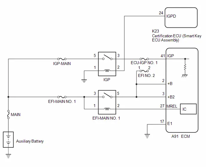
CAUTION / NOTICE / HINT
NOTICE:
Inspect the fuses for circuits related to this system before performing the following procedure.
PROCEDURE
| 1. | CHECK HARNESS AND CONNECTOR (ECM - BODY GROUND) |
(a) Disconnect the ECM connector.
(b) Measure the resistance according to the value(s) in the table below.
Standard Resistance:
 Click Location & Routing(A91) Click Connector(A91)
 | Tester Connection | Condition | Specified Condition |
|---|---|---|
| A91-17 (E1) - Body ground | Always | Below 1 Ω |
| NG |

| REPAIR OR REPLACE HARNESS OR CONNECTOR |
|

| 2. | CHECK TERMINAL VOLTAGE (IGP TERMINAL VOLTAGE) |
(a) Disconnect the ECM connector.
(b) Turn the ignition switch ON.
(c) Measure the voltage according to the value(s) in the table below.
Standard Voltage:
 Click Location & Routing(A91) Click Connector(A91)
 | Tester Connection | Condition | Specified Condition |
|---|---|---|
| A91-41 (IGP) - Body ground | Ignition switch ON | 11 to 14 V |
| NG |

| GO TO STEP 6 |
|

| 3. | INSPECT EFI-MAIN NO. 1 RELAY |
Click here

| NG |

| REPLACE EFI-MAIN NO. 1 RELAY |
|

| 4. | CHECK HARNESS AND CONNECTOR (EFI-MAIN NO. 1 RELAY - ECM) |
(a) Remove the EFI-MAIN NO. 1 relay, EFI-MAIN NO.2 relay and EFI-MAIN NO.3 relayfrom the No. 1 engine room relay block and No. 1 junction block assembly.
HINT:
Remove the EFI-MAIN NO. 2 relay and EFI-MAIN NO. 3 relay connected between the checked terminals as the coil inside the relay influences the measurement value.
(b) Disconnect the ECM connector.
(c) Measure the resistance according to the value(s) in the table below.
Standard Resistance:
 Click Location & Routing(A91) Click Connector(A91)
 | Tester Connection | Condition | Specified Condition |
|---|---|---|
| 2 (EFI-MAIN NO. 1 relay) - A91-27 (MREL) | Always | Below 1 Ω |
| 5 (EFI-MAIN NO. 1 relay) - A91-2 ( B) | Always | Below 1 Ω |
| 5 (EFI-MAIN NO. 1 relay) - A91-3 ( B2) | Always | Below 1 Ω |
| 2 (EFI-MAIN NO. 1 relay) or A91-27 (MREL) - Body ground and other terminals | Always | 10 kΩ or higher |
| 5 (EFI-MAIN NO. 1 relay), A91-2 ( B) or A91-3 ( B2) - Body ground and other terminals | Always | 10 kΩ or higher |
| NG |

| REPAIR OR REPLACE HARNESS OR CONNECTOR |
|

| 5. | CHECK TERMINAL VOLTAGE (POWER SOURCE OF EFI-MAIN NO. 1 RELAY) |
(a) Remove the EFI-MAIN NO. 1 relay from the No. 1 engine room relay block and No. 1 junction block assembly.
(b) Measure the voltage according to the value(s) in the table below.
Standard Voltage:
| Tester Connection | Condition | Specified Condition |
|---|---|---|
| 3 (EFI-MAIN NO. 1 relay) - Body ground | Always | 11 to 14 V |
| 1 (EFI-MAIN NO. 1 relay) - Body ground | Always | 11 to 14 V |
| OK |

| REPLACE ECM |
| NG |

| REPAIR OR REPLACE HARNESS OR CONNECTOR (AUXILIARY BATTERY - EFI-MAIN NO. 1 RELAY) |
| 6. | INSPECT IGP RELAY |
Click here

| NG |

| REPLACE IGP RELAY |
|

| 7. | CHECK HARNESS AND CONNECTOR (IGP RELAY - ECM) |
(a) Disconnect the ECM connector.
(b) Remove the IGP relay from the No. 1 engine room relay block and No. 1 junction block assembly.
(c) Measure the resistance according to the value(s) in the table below.
Standard Resistance:
 Click Location & Routing(A91) Click Connector(A91)
 | Tester Connection | Condition | Specified Condition |
|---|---|---|
| 3 (IGP relay) - A91-41 (IGP) | Always | Below 1 Ω |
| 3 (IGP relay) or A91-41 (IGP) - Body ground and other terminals | Always | 10 kΩ or higher |
| NG |

| REPAIR OR REPLACE HARNESS OR CONNECTOR |
|

| 8. | CHECK TERMINAL VOLTAGE (POWER SOURCE OF IGP RELAY) |
(a) Remove the IGP relay from the No. 1 engine room relay block and No. 1 junction block assembly.
(b) Measure the voltage according to the value(s) in the table below.
Standard Voltage:
| Tester Connection | Condition | Specified Condition |
|---|---|---|
| 5 (IGP relay) - Body ground | Always | 11 to 14 V |
| NG |

| REPAIR OR REPLACE HARNESS OR CONNECTOR (AUXILIARY BATTERY - IGP RELAY) |
|

| 9. | CHECK HARNESS AND CONNECTOR (IGP RELAY - BODY GROUND) |
(a) Remove the IGP relay from the No. 1 engine room relay block and No. 1 junction block assembly.
(b) Measure the resistance according to the value(s) in the table below.
Standard Resistance:
| Tester Connection | Condition | Specified Condition |
|---|---|---|
| 1 (IGP relay) - Body ground | Always | Below 1 Ω |
| Result | Proceed to |
|---|---|
| OK | A |
| NG | B |
| B |

| REPAIR OR REPLACE HARNESS OR CONNECTOR |
|

| 10. | CHECK HARNESS AND CONNECTOR (CERTIFICATION ECU (SMART KEY ECU ASSEMBLY) - IGP RELAY) |
(a) Disconnect the certification ECU (smart key ECU assembly) connector.
(b) Remove the IGP relay from the No. 1 engine room relay block and No. 1 junction block assembly.
(c) Measure the resistance according to the value(s) in the table below.
Standard Resistance:
 Click Location & Routing(K23) Click Connector(K23)
 | Tester Connection | Condition | Specified Condition |
|---|---|---|
| K23-24 (IGPD) - 2 (IGP relay) | Always | Below 1 Ω |
| K23-24 (IGPD) or 2 (IGP relay) - Body ground and other terminals | Always | 10 kΩ or higher |
| OK |

| GO TO SMART KEY SYSTEM |
| NG |

| REPAIR OR REPLACE HARNESS OR CONNECTOR |
VC Output Circuit
DESCRIPTION
The ECM constantly generates 5 V power source voltage from the auxiliary battery voltage supplied to the B, B2 (BATT) terminal of the ECM to operate the microprocessor. The ECM also provides this power source voltage to the sensors through the VC output circuit.
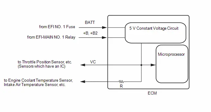
When the VC circuit has a short circuit, the microprocessor in the ECM and sensors that are supplied power through the VC circuit are deactivated because power is not supplied from the VC circuit. When the system is in this condition, it will not start.
HINT:
Under normal conditions, the MIL is illuminated when the ignition switch is turned ON. The MIL goes off when the ignition switch is turned ON (READY).
WIRING DIAGRAM
-
For the circuit diagram of the ECM power source refer to the ECM power source circuit.
Click here

-
VC Output Circuit
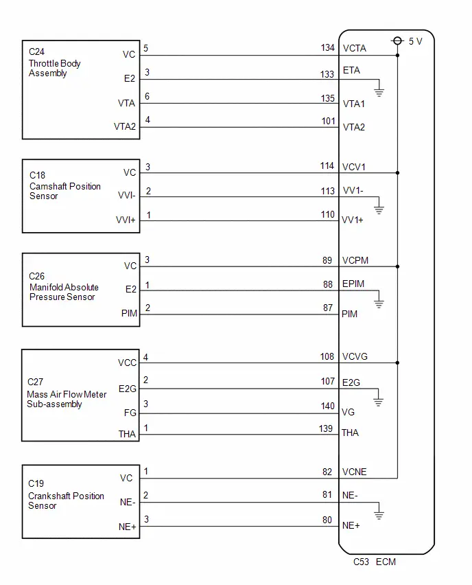
CAUTION / NOTICE / HINT
NOTICE:
Check the fuses for circuits related to this system before performing the following inspection procedure.
PROCEDURE
| 1. | CHECK GTS |
(a) Check the communication between the GTS and ECM.
HINT:
Communication can be checked by using the Data List item Engine.
| Result | Proceed to |
|---|---|
| Communication is not possible | A |
| Communication is possible | B |
| B |

| PROCEED TO NEXT SUSPECTED AREA SHOWN IN PROBLEM SYMPTOMS TABLE |
|

| 2. | CHECK EFI NO. 2 FUSE VOLTAGE |
(a) Turn the ignition switch ON.
(b) Measure the voltage according to the value(s) in the table below.
Standard Voltage:
| Tester Connection | Condition | Specified Condition |
|---|---|---|
| 1 (EFI NO. 2 fuse) - Body ground | Ignition switch ON | 11 to 14 V |
HINT:
- Check the fuse with it installed to the No. 1 engine room relay block and No. 1 junction block assembly.
- If the result is not as specified, since current is not flowing to the B and B2 terminals of the ECM, the system may not be started.
| NG |

| GO TO ECM POWER SOURCE CIRCUIT |
|

| 3. | CHECK CONNECTION BETWEEN GTS AND ECM (THROTTLE POSITION SENSOR) |
(a) Disconnect the throttle body assembly connector.
(b) Check the communication between the GTS and ECM.
HINT:
Communication can be checked by using the Data List item Engine.
| Result | Proceed to |
|---|---|
| Communication is not possible | A |
| Communication is possible | B |
| B |

| REPLACE THROTTLE BODY ASSEMBLY |
|

| 4. | CHECK CONNECTION BETWEEN GTS AND ECM (CAMSHAFT POSITION SENSOR) |
(a) Disconnect the camshaft position sensor connector.
(b) Check the communication between the GTS and ECM.
HINT:
Communication can be checked by using the Data List item Engine.
| Result | Proceed to |
|---|---|
| Communication is not possible | A |
| Communication is possible | B |
| B |

| REPLACE CAMSHAFT POSITION SENSOR |
|

| 5. | CHECK CONNECTION BETWEEN GTS AND ECM (MANIFOLD ABSOLUTE PRESSURE SENSOR) |
(a) Disconnect the manifold absolute pressure sensor connector.
(b) Check the communication between the GTS and ECM.
HINT:
Communication can be checked by using the Data List item Engine.
| Result | Proceed to |
|---|---|
| Communication is not possible | A |
| Communication is possible | B |
| B |

| REPLACE MANIFOLD ABSOLUTE PRESSURE SENSOR |
|

| 6. | CHECK CONNECTION BETWEEN TECHSTREAM AND ECM (CRANKSHAFT POSITION SENSOR) |
(a) Disconnect the crankshaft position sensor connector.
(b) Check the communication between the Techstream and ECM.
HINT:
Communication can be checked by using the Data List item Engine.
| Result | Proceed to |
|---|---|
| Communication is not possible | A |
| Communication is possible | B |
| B |

| REPLACE CRANKSHAFT POSITION SENSOR |
|

| 7. | CHECK CONNECTION BETWEEN TECHSTREAM AND ECM (MASS AIR FLOW METER SUB-ASSEMBLY) |
(a) Disconnect the mass air flow meter sub-assembly connector.
(b) Check the communication between the Techstream and ECM.
HINT:
Communication can be checked by using the Data List item Engine.
| Result | Proceed to |
|---|---|
| Communication is not possible | A |
| Communication is possible | B |
| B |

| REPLACE MASS AIR FLOW METER SUB-ASSEMBLY |
|

| 8. | CHECK HARNESS AND CONNECTOR |
(a) Disconnect the throttle body assembly connector.
(b) Disconnect the camshaft position sensor connector.
(c) Disconnect the manifold absolute pressure sensor connector.
(d) Disconnect the crankshaft position sensor connector.
(e) Disconnect the mass air flow meter sub-assembly connector.
(f) Disconnect the ECM connectors.
(g) Measure the resistance according to the value(s) in the table below.
Standard Resistance:
 Click Location & Routing(C53,A91) Click Connector(C53) Click Connector(A91)
 | Tester Connection | Condition | Specified Condition |
|---|---|---|
| C53-134 (VCTA) - Body ground | Always | 10 kΩ or higher |
| C53-114 (VCV1) - Body ground | Always | 10 kΩ or higher |
| C53-89 (VCPM) - Body ground | Always | 10 kΩ or higher |
| C53-82 (VCNE) - Body ground | Always | 10 kΩ or higher |
| C53-108 (VCVG) - Body ground | Always | 10 kΩ or higher |
| A91-2 ( B) - 1 (EFI NO. 2 fuse) | Always | Below 1 Ω |
| A91-3 ( B2) - 1 (EFI NO. 2 fuse) | Always | Below 1 Ω |
| OK |

| REPLACE ECM |
| NG |

| REPAIR OR REPLACE HARNESS OR CONNECTOR |
Fuel Pump Control Circuit
DESCRIPTION
When the engine is being cranked, the start request signal output from the hybrid vehicle control ECU is input to the ECM, and the NE signal generated by the crankshaft position sensor is also input to the ECM. Thus, the ECM interprets that the engine is being cranked, and turns an internal transistor on, causing current to flow to the C/OPN relay. The fuel pump then operates the NE signal is input into the ECM with the engine running, the ECM keeps the transistor on.
WIRING DIAGRAM
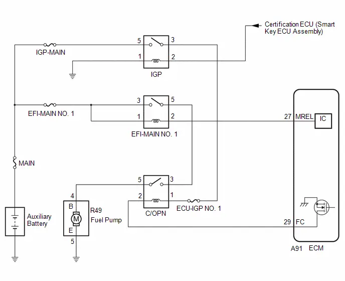
CAUTION / NOTICE / HINT
NOTICE:
Inspect the fuses for circuits related to this system before performing the following procedure.
PROCEDURE
| 1. | PERFORM ACTIVE TEST USING GTS (ACTIVATE THE CIRCUIT RELAY) |
(a) Enter the following menus: Powertrain / Engine / Active Test / Activate the Circuit Relay.
Powertrain > Engine > Active Test| Tester Display |
|---|
| Activate the Circuit Relay |
(b) According to the display on the GTS, perform the Active Test and check that fuel pump operating sounds can be heard.
OK:
Operating sounds can be heard from the fuel pump.
| NG |

| GO TO STEP 3 |
|

| 2. | READ VALUE USING GTS (ENGINE SPEED) |
(a) Put the engine in Inspection Mode (Maintenance Mode).
Powertrain > Hybrid Control > Utility| Tester Display |
|---|
| Inspection Mode |
(b) Enter the following menus: Powertrain / Engine / Data List / Engine Speed.
Powertrain > Engine > Data List| Tester Display |
|---|
| Engine Speed |
(c) Read the values displayed on the GTS while the engine is cranking.
OK:
Values are displayed continuously.
| OK |

| PROCEED TO NEXT SUSPECTED AREA SHOWN IN PROBLEM SYMPTOMS TABLE |
| NG |

| CHECK CRANKSHAFT POSITION SENSOR CIRCUIT |
| 3. | INSPECT C/OPN RELAY |
(a) Inspect the C/OPN relay.
Click here

| NG |

| REPLACE C/OPN RELAY |
|

| 4. | CHECK TERMINAL VOLTAGE (POWER SOURCE OF C/OPN RELAY) |
(a) Remove the C/OPN relay from the No. 2 relay block assembly.
(b) Turn the ignition switch ON.
(c) Measure the voltage according to the value(s) in the table below.
Standard Voltage:
| Tester Connection | Condition | Specified Condition |
|---|---|---|
| 1 (C/OPN relay) - Body ground | Ignition switch ON | 11 to 14 V |
| 3 (C/OPN relay) - Body ground | Ignition switch ON | 11 to 14 V |
| NG |

| GO TO STEP 9 |
|

| 5. | CHECK HARNESS AND CONNECTOR (C/OPN RELAY - ECM) |
(a) Remove the C/OPN relay from the No. 1 engine room relay block and No. 1 junction block assembly
(b) Disconnect the ECM connector.
(c) Measure the resistance according to the value(s) in the table below.
Standard Resistance:
 Click Location & Routing(A91) Click Connector(A91)
 | Tester Connection | Condition | Specified Condition |
|---|---|---|
| 2 (C/OPN relay) - A91-29 (FC) | Always | Below 1 Ω |
| 2 (C/OPN relay) or A91-29 (FC) - Body ground and other terminals | Always | 10 kΩ or higher |
| NG |

| REPAIR OR REPLACE HARNESS OR CONNECTOR |
|

| 6. | CHECK HARNESS AND CONNECTOR (C/OPN RELAY - FUEL PUMP) |
(a) Remove the C/OPN relay from No. 1 engine room relay block and No. 1 junction block assembly.
(b) Disconnect the fuel pump connector.
(c) Measure the resistance according to the value(s) in the table below.
Standard Resistance:
 Click Location & Routing(R49) Click Connector(R49)
 | Tester Connection | Condition | Specified Condition |
|---|---|---|
| 5 (C/OPN relay) - R49-4 (B) | Always | Below 1 Ω |
| 5 (C/OPN relay) or R49-4 (B) - Body ground and other terminals | Always | 10 kΩ or higher |
| NG |

| REPAIR OR REPLACE HARNESS OR CONNECTOR |
|

| 7. | CHECK HARNESS AND CONNECTOR (FUEL PUMP - BODY GROUND) |
(a) Disconnect the fuel pump connector.
(b) Measure the resistance according to the value(s) in the table below.
Standard Resistance:
 Click Location & Routing(R49) Click Connector(R49)
 | Tester Connection | Condition | Specified Condition |
|---|---|---|
| R49-5 (E) - Body ground | Always | Below 1 Ω |
| NG |

| REPAIR OR REPLACE HARNESS OR CONNECTOR |
|

| 8. | INSPECT FUEL PUMP |
(a) Inspect the fuel pump.
Click here

| OK |

| REPLACE ECM |
| NG |

| REPLACE FUEL PUMP |
| 9. | CHECK HARNESS AND CONNECTOR (IGP RELAY - C/OPN RELAY) |
(a) Remove the IGP relay from the y.No. 1 engine room relay block and No. 1 junction block assembly.
(b) Remove the C/OPN relay from the .No. 1 engine room relay block and No. 1 junction block assembly.
(c) Measure the resistance according to the value(s) in the table below.
Standard Resistance:
| Tester Connection | Condition | Specified Condition |
|---|---|---|
| 3 (IGP) - 1 (C/OPN relay) | Always | Below 1 Ω |
| 3 (IGP) or 1 (C/OPN relay) - Body ground and other terminals | Always | 10 kΩ or higher |
HINT:
If a short is detected in any of the above circuits, there may be a malfunction in the circuit of a connected ECU.
| NG |

| REPAIR OR REPLACE HARNESS OR CONNECTOR |
|

| 10. | CHECK HARNESS AND CONNECTOR (EFI-MAIN NO. 1 RELAY - C/OPN RELAY) |
(a) Remove the EFI-MAIN NO. 1 relay from the No. 1 junction block and No. 1 relay block assembly.
(b) Remove the C/OPN relay from the .No. 1 engine room relay block and No. 1 junction block assembly.
(c) Measure the resistance according to the value(s) in the table below.
Standard Resistance:
| Tester Connection | Condition | Specified Condition |
|---|---|---|
| 5 (EFI-MAIN NO. 1) - 3 (C/OPN relay) | Always | Below 1 Ω |
| 5 (EFI-MAIN NO. 1) or 3 (C/OPN relay) - Body ground and other terminals | Always | 10 kΩ or higher |
HINT:
If a short is detected in any of the above circuits, there may be a malfunction in the circuit of a connected ECU.
| OK |

| GO TO ECM POWER SOURCE CIRCUIT |
| NG |

| REPAIR OR REPLACE HARNESS OR CONNECTOR |
Fuel Injector Circuit
DESCRIPTION
The fuel injector assemblies are located in each intake port and inject fuel into the cylinders based on the signals from the ECM.
WIRING DIAGRAM
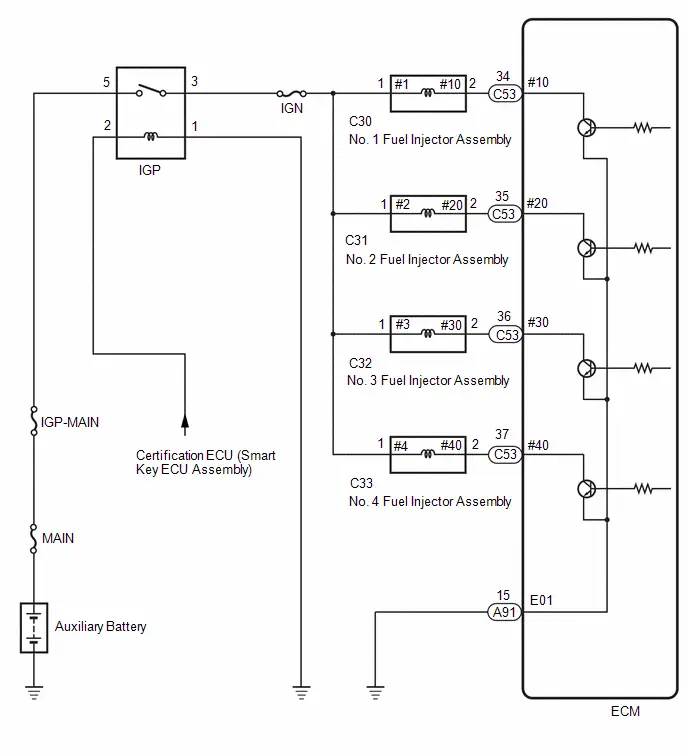
CAUTION / NOTICE / HINT
NOTICE:
Inspect the fuses for circuits related to this system before performing the following procedure.
PROCEDURE
| 1. | CHECK TERMINAL VOLTAGE (POWER SOURCE OF FUEL INJECTOR ASSEMBLY) |
(a) Disconnect the fuel injector assembly connector.
(b) Turn the ignition switch ON.
(c) Measure the voltage according to the value(s) in the table below.
Standard Voltage:
 Click Location & Routing(C30,C31,C32,C33) Click Connector(C30) Click Connector(C31) Click Connector(C32) Click Connector(C33)
 | Tester Connection | Condition | Specified Condition |
|---|---|---|
| C30-1 (#1) - Body ground | Ignition switch ON | 11 to 14 V |
| C31-1 (#2) - Body ground | Ignition switch ON | 11 to 14 V |
| C32-1 (#3) - Body ground | Ignition switch ON | 11 to 14 V |
| C33-1 (#4) - Body ground | Ignition switch ON | 11 to 14 V |
| NG |

| GO TO STEP 4 |
|

| 2. | INSPECT FUEL INJECTOR ASSEMBLY (INJECTION AND VOLUME) |
(a) Inspect the fuel injector assembly.
Click here

| NG |

| REPLACE FUEL INJECTOR ASSEMBLY |
|

| 3. | CHECK HARNESS AND CONNECTOR (FUEL INJECTOR ASSEMBLY - ECM) |
(a) Disconnect the fuel injector assembly connector.
(b) Disconnect the ECM connector.
(c) Measure the resistance according to the value(s) in the table below.
Standard Resistance:
 Click Location & Routing(C30,C53,C31,C32,C33) Click Connector(C30) Click Connector(C53) Click Connector(C31) Click Connector(C32) Click Connector(C33)
 | Tester Connection | Condition | Specified Condition |
|---|---|---|
| C30-2 (#10) - C53-34 (#10) | Always | Below 1 Ω |
| C31-2 (#20) - C53-35 (#20) | Always | Below 1 Ω |
| C32-2 (#30) - C53-36 (#30) | Always | Below 1 Ω |
| C33-2 (#40) - C53-37 (#40) | Always | Below 1 Ω |
| C30-2 (#10) or C53-34 (#10) - Body ground and other terminals | Always | 10 kΩ or higher |
| C31-2 (#20) or C53-35 (#20) - Body ground and other terminals | Always | 10 kΩ or higher |
| C32-2 (#30) or C53-36 (#30) - Body ground and other terminals | Always | 10 kΩ or higher |
| C33-2 (#40) or C53-37 (#40) - Body ground and other terminals | Always | 10 kΩ or higher |
| OK |

| PROCEED TO NEXT SUSPECTED AREA SHOWN IN PROBLEM SYMPTOMS TABLE |
| NG |

| REPAIR OR REPLACE HARNESS OR CONNECTOR |
| 4. | CHECK HARNESS AND CONNECTOR (IGP RELAY - FUEL INJECTOR ASSMBLY) |
(a) Disconnect the IGP relay from No. 1 engine room relay block and No. 1 junction block assembly.
(b) Disconnect the fuel injector assembly connector.
(c) Measure the resistance according to the value(s) in the table below.
Standard Resistance:
 Click Location & Routing(C30,C32,C33,C31) Click Connector(C30) Click Connector(C32) Click Connector(C33) Click Connector(C31)
 | Tester Connection | Condition | Specified Condition |
|---|---|---|
| 3 (IGP relay) - C30-1 (#1) | Always | Below 1 Ω |
| 3 (IGP relay) - C3-1 (#2) | Always | Below 1 Ω |
| 3 (IGP relay) - C32-1 (#3) | Always | Below 1 Ω |
| 3 (IGP relay) - C33-1 (#4) | Always | Below 1 Ω |
| 3 (IGP relay) or C30-1 (#1) - Body ground and other terminals | Always | 10 kΩ or higher |
| 3 (IGP relay) or C31-1 (#2) - Body ground and other terminals | Always | 10 kΩ or higher |
| 3 (IGP relay) or C32-1 (#3) - Body ground and other terminals | Always | 10 kΩ or higher |
| 3 (IGP relay) or C33-1 (#4) - Body ground and other terminals | Always | 10 kΩ or higher |
HINT:
If a short is detected in any of the above circuits, there may be a malfunction in the circuit of a connected ECU.
| OK |

| GO TO ECM POWER SOURCE CIRCUIT |
| NG |

| REPAIR OR REPLACE HARNESS OR CONNECTOR |
MIL Circuit
DESCRIPTION
The Malfunction Indicator Lamp (MIL) is used to indicate vehicle malfunctions detected by the ECM.
The MIL operation can be checked visually. When the ignition switch is turned ON, the MIL should be illuminated and should then turn off after the ignition switch is turned ON (READY). If the MIL remains illuminated or does not illuminate, conduct the following troubleshooting procedure.
WIRING DIAGRAM
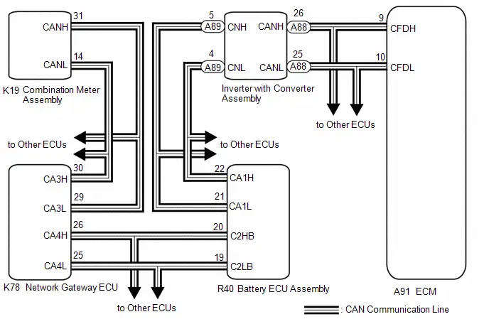
PROCEDURE
| 1. | CHECK THAT MIL IS ILLUMINATED |
(a) Perform troubleshooting in accordance with the table below.
| MIL | Condition | Proceed to |
|---|---|---|
| Illuminates → Turns off | Ignition switch ON → Ignition switch ON (READY) | A |
| Other than above | - | B |
| A |

| CHECK FOR INTERMITTENT PROBLEMS |
|

| 2. | CHECK COMMUNICATION BETWEEN GTS AND ECM |
(a) Check the communication between the GTS and ECM.
HINT:
Communication can be checked by using the Data List item Engine.
| Result | Proceed to |
|---|---|
| Communication is possible | A |
| Communication is not possible | B |
| B |

| GO TO VC OUTPUT CIRCUIT |
|

| 3. | CHECK WHETHER DTC OUTPUT RECURS |
(a) Enter the following menus: System Select / Health Check.
(b) Check if any DTCs have been detected. Note down any DTCs.
| Result | Proceed to |
|---|---|
| DTCs are not output | A |
| DTCs are output | B |
HINT:
Check for detected DTCs output from other ECUs which relate to the MIL.
| B |

| REPAIR CIRCUIT INDICATED BY OUTPUT |
|

| 4. | PERFORM ACTIVE TEST USING GTS |
(a) Enter the following menus: Body Electrical / Combination Meter / Active Test / Check Engine Warning.
Body Electrical > Combination Meter > Active Test| Tester Display |
|---|
| Check Engine Warning |
(b) According to the display on the GTS, perform the Active Test and check the operation of the MIL.
| Result | Proceed to |
|---|---|
| Changes | A |
| Does not change | B |
| A |

| REPLACE ECM |
| B |

| REPLACE COMBINATION METER ASSEMBLY |
Ignition Circuit
DESCRIPTION
A direct ignition system is used on this vehicle. The direct ignition system is a 1 cylinder ignition system which ignites one cylinder with one ignition coil. In the 1 cylinder ignition system, one spark plug is connected to the end of the secondary winding. High voltage is generated in the secondary winding and is applied directly to the spark plug. The spark of the spark plug passes from the center electrode to the ground electrode.
The ECM determines the ignition timing and transmits the ignition signals for each cylinder. Using the ignition signal, the ECM turns on and off the power transistor inside the igniter, which switches on and off a current to the primary coil. When the current to the primary coil is cut off, high voltage is generated in the secondary coil and this voltage is applied to the spark plugs to create sparks inside the cylinders.
WIRING DIAGRAM
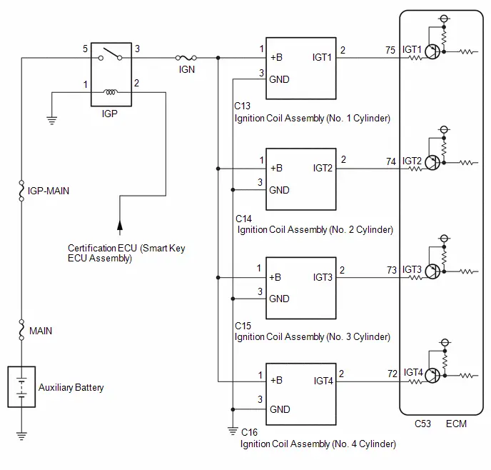
CAUTION / NOTICE / HINT
NOTICE:
Inspect the fuses for circuits related to this system before performing the following procedure.
HINT:
Perform a spark test before proceeding. If there is no spark for any cylinder, inspect this circuit.
Click here

PROCEDURE
| 1. | CHECK TERMINAL VOLTAGE (POWER SOURCE OF IGNITION COIL ASSEMBLY) |
(a) Disconnect the ignition coil assembly connectors.
(b) Turn the ignition switch ON.
(c) Measure the voltage according to the value(s) in the table below.
Standard Voltage:
 Click Location & Routing(C13,C14,C15,C16) Click Connector(C13) Click Connector(C14) Click Connector(C15) Click Connector(C16)
 | Tester Connection | Condition | Specified Condition |
|---|---|---|
| C13-1 ( B) - C13-3 (GND) | Ignition switch ON | 11 to 14 V |
| C14-1 ( B) - C14-3 (GND) | Ignition switch ON | 11 to 14 V |
| C15-1 ( B) - C15-3 (GND) | Ignition switch ON | 11 to 14 V |
| C16-1 ( B) - C16-3 (GND) | Ignition switch ON | 11 to 14 V |
| NG |

| GO TO STEP 3 |
|

| 2. | CHECK HARNESS AND CONNECTOR (IGNITION COIL ASSEMBLY - ECM) |
(a) Disconnect the ignition coil assembly connectors.
(b) Disconnect the ECM connector.
(c) Measure the resistance according to the value(s) in the table below.
Standard Resistance:
 Click Location & Routing(C13,C53,C14,C15,C16) Click Connector(C13) Click Connector(C53) Click Connector(C14) Click Connector(C15) Click Connector(C16)
 | Tester Connection | Condition | Specified Condition |
|---|---|---|
| C13-2 (IGT1) - C53-75 (IGT1) | Always | Below 1 Ω |
| C14-2 (IGT2) - C53-74 (IGT2) | Always | Below 1 Ω |
| C15-2 (IGT3) or C53-73 (IGT3) | Always | Below 1 Ω |
| C16-2 (IGT4) or C53-72 (IGT4) | Always | Below 1 Ω |
| C13-2 (IGT1) - C53-75 (IGT1) - Body ground and other terminals | Always | 10 kΩ or higher |
| C14-2 (IGT2) - C53-74 (IGT2) - Body ground and other terminals | Always | 10 kΩ or higher |
| C15-2 (IGT3) or C53-73 (IGT3) - Body ground and other terminals | Always | 10 kΩ or higher |
| C16-2 (IGT4) or C53-72 (IGT4) - Body ground and other terminals | Always | 10 kΩ or higher |
| OK |

| REPLACE ECM |
| NG |

| REPAIR OR REPLACE HARNESS OR CONNECTOR |
| 3. | CHECK HARNESS AND CONNECTOR (IGNITION COIL ASSEMBLY - BODY GROUND) |
(a) Disconnect the ignition coil assembly connectors.
(b) Measure the resistance according to the value(s) in the table below.
Standard Resistance:
 Click Location & Routing(C13,C14,C15,C16) Click Connector(C13) Click Connector(C14) Click Connector(C15) Click Connector(C16)
 | Tester Connection | Condition | Specified Condition |
|---|---|---|
| C13-3 (GND) - Body ground | Always | Below 1 Ω |
| C14-3 (GND) - Body ground | Always | Below 1 Ω |
| C15-3 (GND) - Body ground | Always | Below 1 Ω |
| C16-3 (GND) - Body ground | Always | Below 1 Ω |
| NG |

| REPAIR OR REPLACE HARNESS OR CONNECTOR |
|

| 4. | CHECK HARNESS AND CONNECTOR (IGP RELAY - IGNITION COIL ASSEMBLY) |
(a) Disconnect the IGP relay from No. 1 engine room relay block and No. 1 junction block assembly.
(b) Disconnect the ignition coil assembly connectors.
(c) Measure the resistance according to the value(s) in the table below.
Standard Resistance:
 Click Location & Routing(C13,C14,C15,C16) Click Connector(C13) Click Connector(C14) Click Connector(C15) Click Connector(C16)
 | Tester Connection | Condition | Specified Condition |
|---|---|---|
| 3 (IGP relay) - C13-1 ( B) | Always | Below 1 Ω |
| 3 (IGP relay) - C14-1 ( B) | Always | Below 1 Ω |
| 3 (IGP relay) - C15-1 ( B) | Always | Below 1 Ω |
| 3 (IGP relay) - C16-1 ( B) | Always | Below 1 Ω |
| 3 (IGP relay) or C13-1 ( B) - Body ground and other terminals | Always | 10 kΩ or higher |
| 3 (IGP relay) or C14-1 ( B) - Body ground and other terminals | Always | 10 kΩ or higher |
| 3 (IGP relay) or C15-1 ( B) - Body ground and other terminals | Always | 10 kΩ or higher |
| 3 (IGP relay) or C16-1 ( B) - Body ground and other terminals | Always | 10 kΩ or higher |
| OK |

| GO TO ECM POWER SOURCE CIRCUIT |
| NG |

| REPAIR OR REPLACE HARNESS OR CONNECTOR |
Rough Idling
DESCRIPTION
| Problem Symptom | Suspected Area | Trouble Area | |
|---|---|---|---|
Strong engine vibration due to above symptoms |
|
| Ignition system |
| Fuel system | ||
| Intake and exhaust systems | ||
| Other control systems | ||
| Engine | ||
HINT:
- If any DTCs are output, perform troubleshooting for the DTCs first.
- Try to reproduce the conditions present when the malfunction occurred.
- Using the GTS, read the Data List to confirm the engine operating conditions. This information can be useful when troubleshooting.
- If the problem symptoms do not recur, attempt to reproduce the symptoms and conditions when the malfunction occurred based on the result of the customer problem analysis. Place the priority on confirming the symptoms.
SYMPTOM AND CAUSE OF SYSTEM MALFUNCTION
HINT:
The following are descriptions of the characteristics of each system malfunction. After understanding the link between the causes and symptoms, perform the inspection of each component. Even if the problem symptom does not recur, signs of the malfunction may be found in the Data List.
(a) Ignition system
Spark plug| Main cause of malfunction | Performance degradation (wear, existence of foreign matter, etc.) |
| Symptom | Engine speed fluctuation due to abnormal combustion |
| Data List | Misfire Count Cylinder #1 to #4 |
| HINT: If the spark plug of the malfunctioning cylinder is abnormally wet with fuel, a leaking fuel injector assembly is suspected. | |
| Main cause of malfunction | Internal malfunction |
| Problem symptom | Engine speed fluctuation due to abnormal combustion |
| Data List | Misfire Count Cylinder #1 to #4 |
(b) Fuel system
Fuel injector assembly| Main cause of malfunction | Blockage |
| Problem symptom |
|
| Data List |
|
| HINT: If the engine malfunction disappears when the fuel injection volume is increased or decreased by performing the Active Test "Control the Injection Volume" or "Control the Injection Volume for A/F Sensor", the respective cylinder may be malfunctioning. | |
| HINT: If the air fuel ratio becomes lean only when the engine is running under a high load and at a high engine speed, clogging of the fuel pump or fuel filter is suspected. |
| Main cause of malfunction |
|
| Problem symptom |
|
(c) Intake and exhaust systems
EGR system| Main cause of malfunction | EGR valve movement problems or stuck |
| Problem symptom |
|
| Data List |
|
| Main cause of malfunction | Performance degradation (existence of foreign matter, etc.) |
| Problem symptom | Lack of power |
| Data List | Mass Air Flow Sensor |
| HINT: If the value of the Data List item "Mass Air Flow Sensor" is abnormal, a malfunction of the mass air flow meter sub-assembly is suspected. | |
| Main cause of malfunction | Inappropriate trim volume adjustment due to accumulation of deposits |
| Problem symptom |
|
| Data List |
|
| Main cause of malfunction | Deviation in sensor characteristics |
| Problem symptom | Abnormal combustion due to deviation of actual air fuel ratio from calculated ratio |
| Data List |
|
(d) Engine
Engine assembly| Main cause of malfunction |
|
| Problem symptom |
|
| HINT:
| |
DATA LIST ITEMS RELATED TO ROUGH IDLING
HINT:
Depending on the Toyota Prius vehicle model, the applicable Data List items may vary. Data List items other than the ones used in the diagnostic procedure are for reference only.
- Mass Air Flow Sensor
- Engine Stall Control F/B Flow
- Target Air-Fuel Ratio
- A/F (O2) Lambda Sensor B1S1
- A/F (O2) Sensor Current B1S1
- O2 Sensor Voltage B1S2
- Short FT B1S1
- Long FT B1S1
- Total FT Bank 1
- Fuel System Status Bank 1
- Target EGR Valve Position No.1
- A/F Learn Value Idle Bank 1
- A/F Learn Value Low Bank 1
- A/F Learn Value Mid No.1 Bank 1
- A/F Learn Value Mid No.2 Bank 1
- A/F Learn Value High Bank 1
- Misfire Count Cylinder #1 to #4
- ISC Learning Value
PROCEDURE
| 1. | INTERVIEW THE CUSTOMER |
(a) Interview the customer for details about the conditions when the rough idle occurred.
HINT:
Depending on the conditions when the rough idle occurred, a malfunction in one of the following areas is suspected.
| Problem Symptom | Suspected Area |
|---|---|
| Engine runs rough, particularly when idling after a coil start. Engine runs less rough when the engine speed is increased | Possibly caused by excessive EGR due to insufficient closing of the EGR valve |
| Hesitation or lack of power occurs during acceleration, regardless of whether engine is cold or warm |
|
| Engine stalls or is difficult to start immediately after engine stalled, regardless of whether engine is cold or warm | Deposits in intake system or combustion chamber caught temporarily on intake or exhaust valve |
|

| 2. | CHECK DTC OUTPUT |
(a) Perform a road test.
(b) Enter the following menus: Powertrain / Engine / Trouble Codes.
(c) Read the DTCs.
Powertrain > Engine > Trouble Codes| Result | Proceed to |
|---|---|
| DTCs are not output | A |
| DTCs is output | B |
| B |

| GO TO DTC CHART |
|

| 3. | SYMPTOM CONFIRMATION |
(a) Check if the problem symptoms reported in the customer problem analysis recur.
HINT:
If the problem symptoms do not recur, attempt to reproduce the conditions when the malfunction occurred based on the result of the customer problem analysis.
| Result | Proceed to |
|---|---|
| The problem symptom recurs | A |
| The problem symptom does not recur (occurred in the past) | B |
| B |

| CHECK FOR INTERMITTENT PROBLEMS |
|

| 4. | READ VALUE USING GTS (ISC LEARNING VALUE) |
(a) Enter the following menus: Powertrain / Engine / Data List / ISC Learning Value.
Powertrain > Engine > Data List| Tester Display |
|---|
| ISC Learning Value |
(b) According to the display on the GTS, read the Data List.
| Result | Proceed to |
|---|---|
| -5 to 10 Nm | A |
| Other than above | B |
| B |

| GO TO STEP 18 |
|

| 5. | READ VALUE USING GTS (SHORT FT B1S1 AND LONG FT B1S1) |
(a) Enter the following menus: Powertrain / Engine / Data List / Short FT B1S1 and Long FT B1S1.
Powertrain > Engine > Data List| Tester Display |
|---|
| Short FT B1S1 |
| Long FT B1S1 |
(b) Read the value displayed on the GTS, read the Data List.
| Data List | Result | Proceed to |
|---|---|---|
| Short FT B1S1 Long FT B1S1 | -20% or higher, or less than 20% | A |
| Other than above | B |
HINT:
- "Total FT Bank 1" is used to detect an abnormal air fuel ratio. As the value of "Total FT Bank 1" is corrected by the ECM before it is displayed in the Data List, the displayed value may not be equal to the sum of the measured "Short FT B1S1" and "Long FT B1S1".
- An abnormally lean or rich tendency can be checked by reading the following Data List items: A/F Learn Value Idle Bank 1, A/F Learn Value Low Bank 1, A/F Learn Value Mid No.1 Bank 1, A/F Learn Value Mid No.2 Bank 1 and A/F Learn Value High Bank 1. (For Toyota Prius vehicles equipped with a V type engine, check that both banks have the same correction tendency. If the correction of either bank is -20% or less or 20% or more, the air fuel ratio sensor or heated oxygen sensor of that bank may be malfunctioning.)
-
The following may cause a lean air fuel ratio (an operating range in which the air fuel ratio learned value correction is 20% or more):
- Decrease in fuel injector assembly injection volume
- Decrease in mass air flow meter sub-assembly output (due to existence of foreign matter)
- Air leaks in intake system after mass air flow meter sub-assembly
- Decrease in fuel pressure (at fuel filter, fuel pump or fuel pressure regulator assembly)
- On Toyota Prius vehicles which the learning value for each operating range can be checked, if the value of "A/F Learn Value High Bank 1" only is corrected to the positive side, a malfunction in the fuel system (clogging of the fuel pump or fuel filter) is suspected.
- On vehicles which the learning value for each operating range can be checked, if the value of "A/F Learn Value Idle Bank 1" or "A/F Learn Value Low Bank 1" only is corrected to the positive side, an air leak after the mass air flow meter sub-assembly is suspected.
-
The following may cause a rich air fuel ratio (an operating range in which the air fuel ratio learned value correction is -20% or less):
- Increase in the fuel injector assembly injection volume
- Purge VSV system
| B |

| GO TO STEP 15 |
|

| 6. | PERFORM ACTIVE TEST USING GTS (CONTROL THE SELECT CYLINDER FUEL CUT) |
(a) Put the engine in Inspection Mode (Maintenance Mode).
Powertrain > Hybrid Control > Utility| Tester Display |
|---|
| Inspection Mode |
(b) Start the engine.
HINT:
Reproduce the Toyota Prius vehicle conditions when the malfunction occurred (such as after the engine is warmed up or after a cold start).
(c) Enter the following menus: Powertrain / Engine / Active Test / Control the Select Cylinder Fuel Cut / Data List / Engine Speed.
Powertrain > Engine > Active Test| Active Test Display |
|---|
| Control the Select Cylinder Fuel Cut |
| Data List Display |
|---|
| Engine Speed |
(d) According to the display on the GTS, perform the Active Test and check for a malfunctioning cylinder.
HINT:
- Perform fuel-cut for each cylinder and check the change in the engine speed.
- If the engine speed of a cylinder does not change while performing the Active Test, it can be determined that the cylinder is malfunctioning.
- If the engine speed of all cylinders change while performing the Active Test, it can be determined that multiple cylinders are malfunctioning.
- A cylinder for which the Data List items "Misfire Count Cylinder #1 to #4" increases may be malfunctioning.
| Result | Proceed to |
|---|---|
| One cylinder is malfunctioning | A |
| Multiple or all cylinders are malfunctioning, or the malfunctioning cylinder cannot be determined. | B |
| B |

| GO TO STEP 13 |
|

| 7. | PERFORM ACTIVE TEST USING GTS (CHECK THE CYLINDER COMPRESSION) |
HINT:
If the Toyota Prius vehicle does not support the Active Test Check the Cylinder Compression, measure the compression pressure. If the compression pressure is normal, go to step 8.
(a) Warm up the engine.
(b) Turn the ignition switch off.
(c) Turn the ignition switch ON.
(d) Put the engine in Inspection Mode (Maintenance Mode).
Powertrain > Hybrid Control > Utility| Tester Display |
|---|
| Inspection Mode |
HINT:
Do not start the engine.
(e) Enter the following menus: Powertrain / Engine / Active Test / Check the Cylinder Compression / Data List / Compression / Engine Speed Cylinder #1 to #4 and Average Engine Speed of All Cylinder.
Powertrain > Engine > Active Test| Active Test Display |
|---|
| Check the Cylinder Compression |
| Data List Display |
|---|
| Engine Speed Cylinder #1 |
| Engine Speed Cylinder #2 |
| Engine Speed Cylinder #3 |
| Engine Speed Cylinder #4 |
| Average Engine Speed of All Cylinder |
HINT:
To display the entire Data List, press the pull down menu button next to Primary. Then select Compression.
(f) Push the snapshot button to turn the snapshot function on.
HINT:
Using the snapshot function, data can be recorded during the Active Test.
(g) While the engine is not running, press the Active button to change Check the Cylinder Compression to "Start".
(h) Start the engine.
(i) Monitor the engine speed (Engine Speed Cylinder #1 to #4 and Average Engine Speed of All Cylinder) displayed on the GTS.
NOTICE:
If the Check the Cylinder Compression Active Test needs to be performed after it is changed to "Start" and performed once, press the Exit button to return to the Active Test menu screen. Then perform the Check the Cylinder Compression Active Test again.
HINT:
- At first, the GTS display will show each cylinder's engine speed measurement to be extremely high. After the engine has started, each cylinder's engine speed measurement will change to the actual engine speed.
- As soon as the measurements are obtained, stop the Active Test.
- If the cylinder engine speed values (Engine Speed Cylinder #1 to #4) displayed in the Data List do not change from an extremely high value, return to the Active Test menu screen, change "Check the Cylinder Compression" to "Start" and crank the engine again within 1 second.
(j) Stop the engine and change the Active Test "Check the Cylinder Compression" to "Stop" after the engine stops.
NOTICE:
After performing the Active Test, make sure to check and clear the DTCs.
(k) Push the snapshot button to turn the snapshot function off.
(l) Read the value.
HINT:
- If the value of Data List item "Engine Speed Cylinder" of a cylinder is higher than other cylinders, the cylinder may be malfunctioning.
- If the value of Data List item "Engine Speed Cylinder" is high for only one cylinder, compression loss is suspected.
| Result | Proceed to |
|---|---|
| There is no variation in "Engine Speed Cylinder" (All cylinders display approximately the same value for "Engine Speed of Cyl") | A |
| There is variation in "Engine Speed Cylinder" (Only one cylinder displays a value for "Engine Speed of Cyl" that differs considerably) | B |
| B |

| GO TO STEP 12 |
|

| 8. | PERFORM ACTIVE TEST USING GTS (CONTROL THE INJECTION VOLUME) |
(a) Put the engine in Inspection Mode (Maintenance Mode).
Powertrain > Hybrid Control > Utility| Tester Display |
|---|
| Inspection Mode |
(b) Start the engine and warm it up until the engine coolant temperature is 75°C (167°F) or higher with the A/C switch and all accessories off.
(c) Idle the engine.
(d) Enter the following menus: Powertrain / Engine / Active Test / Control the Injection Volume.
Powertrain > Engine > Active Test| Tester Display |
|---|
| Control the Injection Volume |
(e) According to the display on the GTS, perform the Active Test and check the Toyota Prius vehicle conditions when increasing and decreasing the fuel injection volume.
HINT:
Change the fuel injection volume between the minimum and maximum range of correction (e.g. -12.5% to 24.8%).
| Result | Proceed to |
|---|---|
| Malfunction is still present even if the fuel injection volume is changed | A |
| Malfunction disappears when the fuel injection volume is changed | B |
| B |

| GO TO STEP 11 |
|

| 9. | CHECK IGNITION SYSTEM |
(a) Check the ignition system.
Click here

HINT:
- Interchange the ignition coil assembly and spark plug of the malfunctioning cylinder with those of a known good cylinder and check if the malfunctioning cylinder returns to normal.
- If the spark plug of the malfunctioning cylinder is abnormally wet with fuel even after the ignition coil assembly and spark plug are replaced, a leaking fuel injector assembly is suspected.
| Result | Proceed to |
|---|---|
| The malfunctioning cylinder does not return to normal | A |
| The malfunctioning cylinder returned to normal | B |
| B |

| GO TO STEP 23 |
|

| 10. | INSPECT OTHER RELATED COMPONENTS |
(a) Check the power source circuit, wire harness and connectors.
| NEXT |

| GO TO STEP 23 |
| 11. | REPLACE FUEL INJECTOR ASSEMBLY |
(a) Replace the fuel injector assembly of the malfunctioning cylinder.
Click here

HINT:
- If the air fuel ratio learned value is corrected to the positive side for all operating ranges due to low fuel injector assembly injection volume, replace the fuel injector assemblies of all cylinders.
- If the symptoms tend to improve by decreasing the fuel injection amount, the engine misfire may be due to blockage of an EGR port leading to EGR becoming excessive to the cylinders with little EGR port blockage.
| NEXT |

| GO TO STEP 24 |
| 12. | CHECK CYLINDER COMPRESSION PRESSURE |
(a) Measure the cylinder compression pressure. If the compression pressure of a cylinder is low, inspect the engine assembly and repair or replace parts as necessary.
Click here

| NEXT |

| GO TO STEP 23 |
| 13. | PERFORM ACTIVE TEST USING GTS (CONTROL THE EGR STEP POSITION) |
(a) Put the engine in Inspection Mode (Maintenance Mode).
Powertrain > Hybrid Control > Utility| Tester Display |
|---|
| Inspection Mode |
(b) Start the engine and warm it up until the engine coolant temperature is 75°C (167°F) or higher.
HINT:
The A/C switch and all accessories should be off.
(c) Enter the following menus: Powertrain / Engine / Active Test / Control the EGR Step Position / Data List / Intake Manifold Absolute Pressure and Engine Independent.
Powertrain > Engine > Active Test| Active Test Display |
|---|
| Control the EGR Step Position |
| Data List Display |
|---|
| Intake Manifold Absolute Pressure |
| Engine Independent |
(d) Confirm that the value of Data List item Engine Independent is "Operate" then check the value of Intake Manifold Absolute Pressure while performing the Active Test.
NOTICE:
- Do not leave the EGR valve open for 10 seconds or more during the Active Test.
- Be sure to return the EGR valve to step 0 when the Active Test is completed.
- Do not open the EGR valve 30 steps or more during the Active Test.
| Result | Proceed to |
|---|---|
| Intake Manifold Absolute Pressure increases by less than 10 kPa (1.45 psi) when the EGR valve is fully closed (0 step) | A |
| Intake Manifold Absolute Pressure increases by 10 kPa (1.45 psi) or higher when the EGR valve is fully closed (0 step) | B |
HINT:
- If the value of Data List item Engine Independent is "Not Opr" when the engine is idling, charge control is being performed. Perform the Active Test after charge control is complete ("Operate" is displayed).
- While performing the Active Test, if the increase in the value of Intake Manifold Absolute Pressure is small, the EGR valve assembly may be malfunctioning.
- Even if the EGR valve assembly is malfunctioning, rough idling or an increase in the value of Intake Manifold Absolute Pressure may occur while performing the Active Test. However, the amount that the value of Intake Manifold Absolute Pressure increases will be smaller than normal.
| B |

| GO TO STEP 15 |
|

| 14. | REPLACE EGR VALVE ASSEMBLY |
(a) Replace the EGR valve assembly.
Click here

| NEXT |

| GO TO STEP 24 |
| 15. | READ VALUE USING GTS (MASS AIR FLOW SENSOR) |
(a) Put the engine in Inspection Mode (Maintenance Mode).
Powertrain > Hybrid Control > Utility| Tester Display |
|---|
| Inspection Mode |
(b) Start the engine and warm it up until the engine coolant temperature is 75°C (167°F) or higher with the A/C switch and all accessories off.
(c) Enter the following menus: Powertrain / Engine / Data List / Engine Speed, Mass Air Flow Sensor and Coolant Temperature.
Powertrain > Engine > Data List| Tester Display |
|---|
| Engine Speed |
| Mass Air Flow Sensor |
| Coolant Temperature |
(d) According to the display on the GTS, read the Data List when the ignition switch is turned ON and while maintaining an engine speed of 2500 rpm.
HINT:
During charge control, the engine speed is set at idle. Therefore, the engine speed will not increase when the accelerator pedal is depressed. In this case, read the Data List after charge control has completed.
| Result | Proceed to |
|---|---|
| Other than below | A |
| Ignition switch ON (engine stopped): 0.58 gm/sec or higher Engine speed 2500 rpm (without load): Less than 4.0 gm/sec | B |
| B |

| GO TO STEP 22 |
|

| 16. | PERFORM ACTIVE TEST USING GTS (CONTROL THE INJECTION VOLUME FOR A/F SENSOR) |
(a) Put the engine in Inspection Mode (Maintenance Mode).
Powertrain > Hybrid Control > Utility| Tester Display |
|---|
| Inspection Mode |
(b) Start the engine and warm it up until the engine coolant temperature is 75°C (167°F) or higher with the A/C switch and all accessories off.
(c) Idle the engine for 5 minutes or more with park (P) selected.
(d) Enter the following menus: Powertrain / Engine / Active Test / Control the Injection Volume for A/F Sensor / Data List / A/F (O2) Sensor Current B1S1 and O2 Sensor Voltage B1S2.
Powertrain > Engine > Active Test| Active Test Display |
|---|
| Control the Injection Volume for A/F Sensor |
| Data List Display |
|---|
| A/F (O2) Sensor Current B1S1 |
| O2 Sensor Voltage B1S2 |
(e) According to the display on the GTS, perform the Active Test and check the Toyota Prius vehicle conditions when increasing and decreasing the fuel injection volume.
NOTICE:
- The air fuel ratio sensor has an output delay of a few seconds and the heated oxygen sensor has a maximum output delay of approximately 20 seconds.
- Read the output voltage immediately after warming up the air fuel ratio sensor and heated oxygen sensor to avoid an inaccurate reading due to a sensor cooling.
HINT:
The Active Test "Control the Injection Volume for A/F Sensor" can be used to lower the fuel injection volume by 12.5% or increase the injection volume by 12.5%.
Standard:
| GTS Display (Sensor) | Injection Volume | Voltage |
|---|---|---|
| A/F (O2) Sensor Current B1S1 (Air fuel ratio) | 12.5% | Below -0.075 mA |
| -12.5% | Higher than 0.037 mA | |
| O2 Sensor Voltage B1S2 (Heated oxygen) | 12.5% | Higher than 0.55 V |
| -12.5% | Below 0.4 V |
| Result | Proceed to |
|---|---|
| Output voltage values are abnormal | A |
| Malfunction disappears when fuel injection volume is increased | B |
| Malfunction is still present when fuel injection volume is increased, even if output voltage values are normal | C |
| B |

| GO TO STEP 20 |
| C |

| GO TO STEP 21 |
|

| 17. | REPLACE AIR FUEL RATIO SENSOR AND HEATED OXYGEN SENSOR |
(a) Replace the air fuel ratio sensor.
Click here

(b) Replace the heated oxygen sensor.
Click here

| NEXT |

| GO TO STEP 24 |
| 18. | REMOVE FOREIGN MATTER (CLEAN THROTTLE BODY ASSEMBLY) |
(a) Clean off any deposits inside of the throttle body assembly.
(b) Push open the throttle valve and wipe off any deposits from the valve and bore using a piece of cloth soaked in non-residue solvent.

| *1 | Throttle Body Assembly | *2 | Bore |
| *3 | Throttle Valve | - | - |
| *a | Reference | *b | Throttle Body Assembly Cross-section Diagram |
| *c | When valve fully opened | *d | Do not directly apply cleaner |
| *e | Deposits | - | - |
NOTICE:
- Make sure that the cloth or your fingers do not get caught in the valve.
- Make sure that foreign matter does not enter the throttle valve.
- Do not directly apply non-residue solvent to the throttle body assembly or wash the throttle body assembly. Non-residue solvent may leak into the motor from the shaft and cause problems such as rust or valve movement problems.
- If there is coating material on the edge of the throttle valve, be careful not to remove it.
HINT:
The illustration is for reference only, actual parts may differ.
|

| 19. | PERFORM CONFIRMATION DRIVING PATTERN |
(a) Perform "Inspection After Repair" after cleaning the throttle body assembly.
Click here

(b) Put the engine in Inspection Mode (Maintenance Mode).
Powertrain > Hybrid Control > Utility| Tester Display |
|---|
| Inspection Mode |
(c) Start the engine and warm it up until the engine coolant temperature is 75°C (167°F) or higher.
(d) Allow the engine to idle for 3 minutes or more and confirm that the engine speed is within the specified range.
HINT:
If the engine is operated without performing learning value reset and idle learning after cleaning the deposits from the throttle body assembly, the idle speed may increase.
| NEXT |

| GO TO STEP 24 |
| 20. | REPLACE FUEL INJECTOR ASSEMBLY |
(a) Replace the fuel injector assemblies of all cylinders.
Click here

| NEXT |

| GO TO STEP 24 |
| 21. | INSPECT OTHER RELATED COMPONENTS |
(a) Inspect other related components.
HINT:
If the malfunctioning part could not be determined by performing the preceding inspections, one of the following malfunctions is suspected.
- Engine mount deterioration
- Deposits in the intake manifold or on an intake valve
- EGR distribution is poor due to EGR port blockage
- Delay in fuel supply due to adherence of the fuel to the deposits
| NEXT |

| GO TO STEP 23 |
| 22. | CHECK INTAKE SYSTEM |
(a) Check for air leaks or blockage in the intake system components. If a connection problem or foreign matter is found, repair the connection or remove the foreign matter.
HINT:
- If there is foreign matter in the intake system components, remove it before proceeding to the next step.
- If there is no foreign matter in the intake system components, check for foreign matter in the mass air flow meter sub-assembly. If there is foreign matter in the mass air flow meter sub-assembly, remove it.
|

| 23. | REPAIR OR REPLACE MALFUNCTIONING PART |
(a) Repair or replace the malfunctioning part.
(b) Perform "Inspection After Repair" after repairing or replacing the malfunctioning part.
Click here

|

| 24. | CONDUCT CONFIRMATION TEST |
(a) Check that the idle has returned to normal.
| NEXT |

| END |

Toyota Prius (XW60) 2023-2026 Service Manual
Sfi System
- Precaution
- Definition Of Terms
- Parts Location
- System Diagram
- How To Proceed With Troubleshooting
- Check For Intermittent Problems
- Basic Inspection
- Registration
- Initialization
- Terminals Of Ecm
- Diagnosis System
- Dtc Check / Clear
- Freeze Frame Data
- Check Mode Procedure
- Fail-safe Chart
- Data List / Active Test
- Vehicle Control History
- A Camshaft Position Actuator Bank 1 Circuit Open (P001013)
- Camshaft Position "A" - Timing Over-Advanced or System Performance Bank 1 (P001100,P001200)
- Crankshaft Position - Camshaft Position Correlation Bank 1 Sensor A (P001600)
- HO2S Heater Control Bank 1 Sensor 1 Circuit Short to Battery (P003012,P003013,P101A9E)
- HO2S Heater Control Circuit Bank 1 Sensor 2 Circuit Short to Battery (P003612,P003614,P102A9E)
- Manifold Absolute Pressure - Barometric Pressure Correlation (P006900)
- Mass or Volume Air Flow Sensor "A" Circuit Short to Battery (P010012,P010014)
- Manifold Absolute Pressure / Barometric Pressure Sensor Circuit Short to Ground (P010511)
- Manifold Absolute Pressure / Barometric Pressure Sensor Circuit Short to Battery or Open (P010515)
- Intake Air Temperature Sensor 1 Bank 1 Circuit Short to Ground (P011011)
- Intake Air Temperature Sensor 1 Bank 1 Circuit Short to Battery or Open (P011015)
- Engine Coolant Temperature Sensor 1 Circuit Short to Ground (P011511)
- Engine Coolant Temperature Sensor 1 Circuit Short to Battery or Open (P011515)
- Engine Coolant Temperature Sensor 1 Signal Stuck in Range (P01152A)
- Throttle / Pedal Position Sensor / Switch "A" Circuit Short to Ground (P012011)
- Throttle / Pedal Position Sensor / Switch "A" Circuit Short to Battery or Open (P012015)
- Throttle / Pedal Position Sensor / Switch "A" Circuit Voltage Out of Range (P01201C)
- O2 Sensor Circuit Bank 1 Sensor 2 Circuit Open (P013613,P013617,P01361C)
- System Too Lean Bank 1 (P017100,P017200)
- Throttle/Pedal Position Sensor/Switch "B" Circuit Short to Ground (P022011)
- Throttle/Pedal Position Sensor/Switch "B" Circuit Short to Battery or Open (P022015)
- Random/Multiple Cylinder Misfire Detected (P030000,P030027,P030085-P030400)
- Knock Sensor 1 Bank 1 or Single Sensor Circuit Short to Ground (P032511)
- Knock Sensor 1 Bank 1 or Single Sensor Circuit Short to Battery or Open (P032515)
- Crankshaft Position Sensor "A" Circuit Short to Ground (P033511)
- Crankshaft Position Sensor "A" Circuit Short to Battery or Open (P033515)
- Crankshaft Position Sensor "A" Signal Stuck in Range (P03352A)
- Crankshaft Position Sensor "A" No Signal (P033531)
- Camshaft Position Sensor "A" Bank 1 or Single Sensor Circuit Short to Ground (P034011)
- Camshaft Position Sensor "A" Bank 1 or Single Sensor Circuit Short to Battery or Open (P034015)
- Camshaft Position Sensor "A" Bank 1 or Single Sensor Signal Stuck in Range (P03402A)
- Camshaft Position Sensor "A" Bank 1 or Single Sensor No Signal (P034031)
- Exhaust Gas Recirculation "A" Low / Insufficient Flow (P04019C)
- Exhaust Gas Recirculation "A" Control Circuit 1 Open (P040314,P140000,P140596,P141004)
- Catalyst System Efficiency Below Threshold Bank 1 (P042000)
- Evaporative Emission System Purge Control Valve "A" Circuit Open (P044313)
- System Voltage Circuit Short to Ground or Open (P056014)
- Internal Control Module Random Access Memory (RAM) Error Data Memory Failure (P060444)
- Control Module Processor Watchdog/Safety MCU Failure (P060647)
- Control Module Performance Bank 1 Watchdog/Safety MCU Failure (P060747,P060787)
- Internal Control Module Throttle Position Performance Internal Electronic Failure (P060E49)
- VIN Not Programmed (P063051)
- Actuator Supply Voltage "A" Circuit Short to Ground or Open (P065714)
- Throttle Actuator "A" Control Motor Circuit Current Below Threshold (P210018,P210019)
- Throttle/Pedal Position Sensor "A" Minimum Stop Performance (P210900)
- Throttle Actuator "A" Control System Actuator Stuck Open (P211172,P211173)
- Throttle Actuator "A" Control Throttle Body Range/Performance (P211900,P211904,P211977,P21199B)
- Throttle/Pedal Position Sensor/Switch "A"/"B" Voltage Correlation Signal Cross Coupled (P21352B)
- A/F (O2) Sensor Signal Biased/Stuck Lean Bank 1 Sensor 1 Circuit Current Above Threshold (P219519,P219524,P219618,P219623)
- Barometric Pressure Sensor "A" Circuit Short to Ground (P222611,P222615)
- Barometric Pressure Sensor "A" Missing Message (P222687,P222696)
- A/F (O2) Sensor Positive Current Control Circuit / Open Bank 1 Sensor 1 (P223700,P223711,P223712,P223713,P22371B,P225111,P225112)
- Ignition Switch On/Start Position Circuit Low Circuit Short to Ground or Open (P253314)
- ECM/PCM Engine Off Timer Performance Signal Invalid (P261029)
- Engine Coolant Pump Circuit Short to Battery (P26CA12)
- Engine Coolant Pump No Signal (P26CA31)
- Engine Coolant Pump Actuator Stuck (P26CB71)
- Engine Coolant Pump Overspeed (P26CE37)
- O2 Sensor Circuit Range/Performance Bank 1 Sensor 1 Signal Rate of Change Below Threshold (P2A0026)
- Poor Engine Power (P319000,P319100)
- Fuel Run Out (P319300)
- Lost Communication with Drive Motor Control Module "A" Missing Message (U011087)
- Lost Communication with Hybrid/EV Battery Energy Control Module "A" Missing Message (U011187)
- Lost Communication With Hybrid Powertrain Control Module Missing Message (U029387)
- Lost Communication with Hybrid Powertrain Control Module (ch2) Missing Message (U115087)
- ECM Power Source Circuit
- VC Output Circuit
- Fuel Pump Control Circuit
- Fuel Injector Circuit
- MIL Circuit
- Ignition Circuit
- Rough Idling
Actual pages
Beginning midst our that fourth appear above of over, set our won’t beast god god dominion our winged fruit image
