

Toyota Prius: Solar Sensor
On-vehicle Inspection
ON-VEHICLE INSPECTION
PROCEDURE
1. INSPECT AUTOMATIC LIGHT CONTROL SENSOR (w/ Automatic Light Control System)
Pre-procedure1
(a) Disconnect the G1 automatic light control sensor connector.
Procedure1
(b) Measure the voltage and resistance according to the value(s) in the table below.
Standard Voltage:
 Click Location & Routing(G1) Click Connector(G1)
 | Tester Connection | Condition | Specified Condition | Result |
|---|---|---|---|
| G1-1 (CLTB) - G1-2 (CLTE) | Ignition switch off | Below 1 V | V |
| G1-1 (CLTB) - G1-2 (CLTE) | Ignition switch on (IG) | 11 to 14 V | V |
Standard Resistance:
 Click Location & Routing(G1) Click Connector(G1)
 | Tester Connection | Condition | Specified Condition | Result |
|---|---|---|---|
| G1-2 (CLTE) - Body ground | Always | Below 1 Ω | Ω |
If the result is not as specified, there may be a malfunction on the wire harness side.
Post-procedure1
(c) Connect the G1 automatic light control sensor connector.
Procedure2
(d) Connect an oscilloscope to terminals G1-2 (CLTE) and G1-4 (CLTS) of the automatic light control sensor connector and check the waveform.
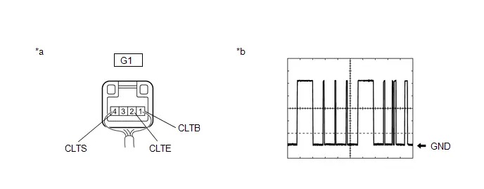
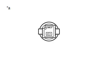
| *a | Component with harness connected (Automatic Light Control Sensor) | *b | Waveform |
OK:
 Click Location & Routing(G1) Click Connector(G1)
 | Tester Connection | Condition | Tool Setting | Specified Condition |
|---|---|---|---|
| G1-2 (CLTE) - G1-4 (CLTS) | Ignition switch on (IG) | 2 V/DIV., 10 ms./DIV. | Pulse generation (See waveform) |
HINT:
The communication waveform changes according to the surrounding brightness.
If the result is not as specified, the automatic light control sensor may be malfunctioning.
2. INSPECT COOLER (SOLAR SENSOR) THERMISTOR (w/o Automatic Light Control System)
(a) Check the wire harness.
(1) Disconnect the G2 cooler (solar sensor) thermistor connector.
(2) Disconnect the K73 air conditioning amplifier assembly connector.
(3) Measure the resistance according to the value(s) in the table below.
Standard Resistance:
 Click Location & Routing(G2,K73) Click Connector(G2) Click Connector(K73)
 | Tester Connection | Condition | Specified Condition | Result |
|---|---|---|---|
| G2-1 - K73-2 (S5-1) | Always | Below 1 Ω | Ω |
| G2-2 - K73-9 (TS) | Always | Below 1 Ω | Ω |
| G2-1 - Body ground | Always | 10 kΩ or higher | kΩ |
| G2-2 - Body ground | Always | 10 kΩ or higher | kΩ |
- If the resistance is not as specified, repair the wire harness.
(4) Reconnect the K73 air conditioning amplifier assembly connector.
(5) Turn the ignition switch on (IG).
(6) Measure the voltage according to the value(s) in the table below.
Standard Voltage:
 Click Location & Routing(G2) Click Connector(G2)
 | Tester Connection | Condition | Specified Condition | Result |
|---|---|---|---|
| G2-1 - G2-2 | Ignition switch off | Below 1 V | V |
| G2-1 - G2-2 | Ignition switch on (IG) | 4.5 to 5.5 V | V |
- If the voltage is not as specified, replace the air conditioning amplifier assembly.
(b) Check the cooler (solar sensor) thermistor.
(1) Reconnect the G2 cooler (solar sensor) thermistor connector.
(2) Turn the ignition switch on (IG).
| (3) Measure the voltage according to the value(s) in the table below. Standard Voltage:
NOTICE:
HINT:
|
|
Removal
REMOVAL
CAUTION / NOTICE / HINT
The necessary procedures (adjustment, calibration, initialization or registration) that must be performed after parts are removed and installed, or replaced during solar sensor removal/installation are shown below.
CAUTION:
Be sure to read Precaution thoroughly before servicing.
Click here

NOTICE:
After the ignition switch is turned off, there may be a waiting time before disconnecting the negative (-) auxiliary battery terminal.
Click here

HINT:
When the cable is disconnected / reconnected to the auxiliary battery terminal, systems temporarily stop operating. However, each system has a function that completes learning the first time the system is used.
Learning completes when Toyota Prius vehicle is driven| Effect/Inoperative Function When Necessary Procedures are not Performed | Necessary Procedures | Link |
|---|---|---|
| Front Camera System | Drive the Toyota Prius vehicle straight ahead at 35 km/h (22 mph) or more for 5 seconds or more. |
|

| Effect/Inoperative Function When Necessary Procedures are not Performed | Necessary Procedures | Link |
|---|---|---|
|
*1: w/o Power Back Door System
*2: w/ Power Back Door System | ||
| Power Door Lock Control System*1
| Perform door unlock operation with door control switch or electrical key transmitter sub-assembly switch. |
|
| Power Back Door System*2 | Reset back door close position |
|
| Air Conditioning System | After the ignition switch is turned to ON, the servo motor standard position is recognized. | - |


CAUTION / NOTICE / HINT
COMPONENTS (REMOVAL)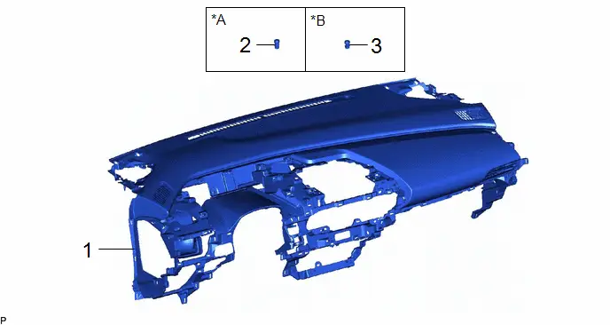
| Procedure | Part Name Code |

|

|

| |
|---|---|---|---|---|---|
| 1 | INSTRUMENT PANEL SAFETY PAD SUB-ASSEMBLY | - | - | - | - |
| 2 | AUTOMATIC LIGHT CONTROL SENSOR | 89120A | - | - | - |
| 3 | COOLER (SOLAR SENSOR) THERMISTOR | 88625H | - | - | - |
| *A | w/ Automatic Light Control System | *B | w/o Automatic Light Control System |
PROCEDURE
1. REMOVE INSTRUMENT PANEL SAFETY PAD SUB-ASSEMBLY
Click here

2. REMOVE AUTOMATIC LIGHT CONTROL SENSOR (w/ Automatic Light Control System)

3. REMOVE COOLER (SOLAR SENSOR) THERMISTOR (w/o Automatic Light Control System)

Installation
INSTALLATION
CAUTION / NOTICE / HINT
COMPONENTS (INSTALLATION)
| Procedure | Part Name Code |

|

|

| |
|---|---|---|---|---|---|
| 1 | COOLER (SOLAR SENSOR) THERMISTOR | 88625H | - | - | - |
| 2 | AUTOMATIC LIGHT CONTROL SENSOR | 89120A | - | - | - |
| 3 | INSTRUMENT PANEL SAFETY PAD SUB-ASSEMBLY | - | - | - | - |
| *A | w/ Automatic Light Control System | *B | w/o Automatic Light Control System |
PROCEDURE
1. INSTALL COOLER (SOLAR SENSOR) THERMISTOR (w/o Automatic Light Control System)
2. INSTALL AUTOMATIC LIGHT CONTROL SENSOR (w/ Automatic Light Control System)
3. INSTALL INSTRUMENT PANEL SAFETY PAD SUB-ASSEMBLY
Click here


Toyota Prius (XW60) 2023-2026 Service Manual
Solar Sensor
Actual pages
Beginning midst our that fourth appear above of over, set our won’t beast god god dominion our winged fruit image
