

Toyota Prius: Seat Heater System
- Precaution
- Parts Location
- System Diagram
- How To Proceed With Troubleshooting
- Operation Check
- Problem Symptoms Table
- Terminals Of Ecu
- Data List / Active Test
- Diagnostic Trouble Code Chart
- Front Right Seat Heat Sensor Circuit Short to Ground (B14C011,B14C015)
- Seat Heater for Front Right Seat does not Operate
- Seat Heater for Rear Right Seat does not Operate
Precaution
PRECAUTION
PRECAUTIONS FOR DISCONNECTING CABLE FROM NEGATIVE (-) AUXILIARY BATTERY TERMINAL
NOTICE:
After the ignition switch is turned off, there may be a waiting time before disconnecting the negative (-) auxiliary battery terminal.
Click here

HINT:
When disconnecting and reconnecting the auxiliary battery, there is an automatic learning function that completes learning when the respective system is used.
Click here


Parts Location
PARTS LOCATION
ILLUSTRATION
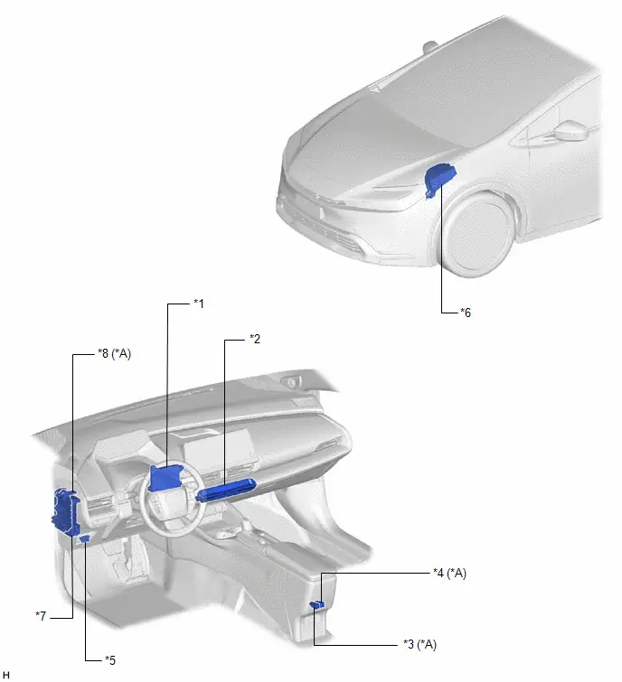
| *A | w/ Rear Seat Heater | - | - |
| *1 | AIR CONDITIONING AMPLIFIER ASSEMBLY | *2 | AIR CONDITIONING CONTROL ASSEMBLY |
| *3 | REAR SEAT HEATER SWITCH LH | *4 | REAR SEAT HEATER SWITCH RH |
| *5 | DLC3 | *6 | NO. 1 ENGINE ROOM RELAY BLOCK AND NO. 1 JUNCTION BLOCK ASSEMBLY - ECU-IGP NO. 3 FUSE - S/HTR RR FUSE |
| *7 | POWER DISTRIBUTION BOX ASSEMBLY - S/HTR F/L FUSE - S/HTR F/R FUSE | *8 | NO. 2 INSTRUMENT PANEL RELAY BLOCK - S HTR RL RELAY - S HTR RR RELAY |
ILLUSTRATION
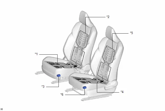
| *1 | FRONT SEAT CUSHION HEATER ASSEMBLY RH | *2 | FRONT SEATBACK HEATER ASSEMBLY RH |
| *3 | SEAT HEATER CONTROL SUB-ASSEMBLY RH | *4 | FRONT SEAT CUSHION HEATER ASSEMBLY LH |
| *5 | FRONT SEATBACK HEATER ASSEMBLY LH | *6 | SEAT HEATER CONTROL SUB-ASSEMBLY LH |
ILLUSTRATION
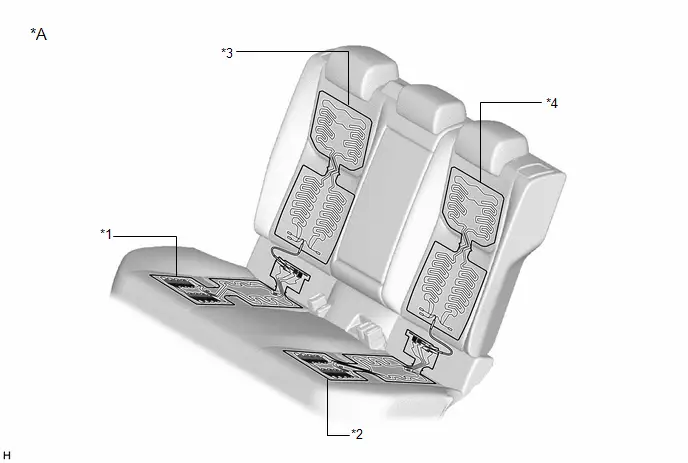
| *A | w/ Rear Seat Heater | - | - |
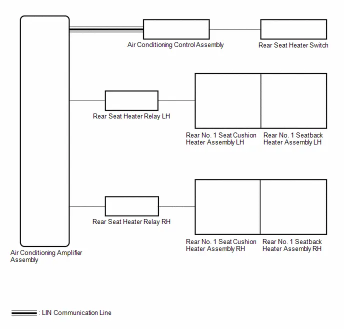
| *1 | REAR NO. 1 SEAT CUSHION HEATER ASSEMBLY RH | *2 | REAR NO. 1 SEAT CUSHION HEATER ASSEMBLY LH |
| *3 | REAR NO. 1 SEATBACK HEATER ASSEMBLY RH | *4 | REAR NO. 1 SEATBACK HEATER ASSEMBLY LH |
System Diagram
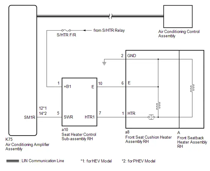
SYSTEM DIAGRAM
FRONT SEAT HEATER
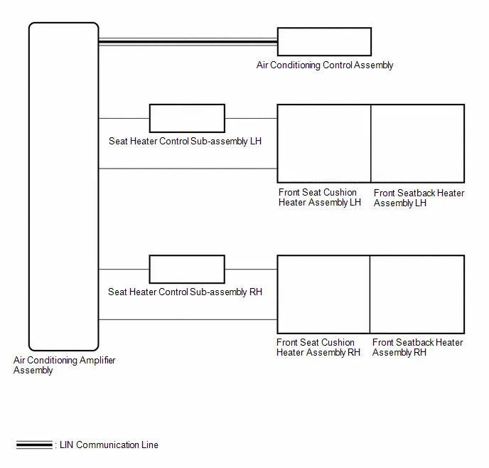
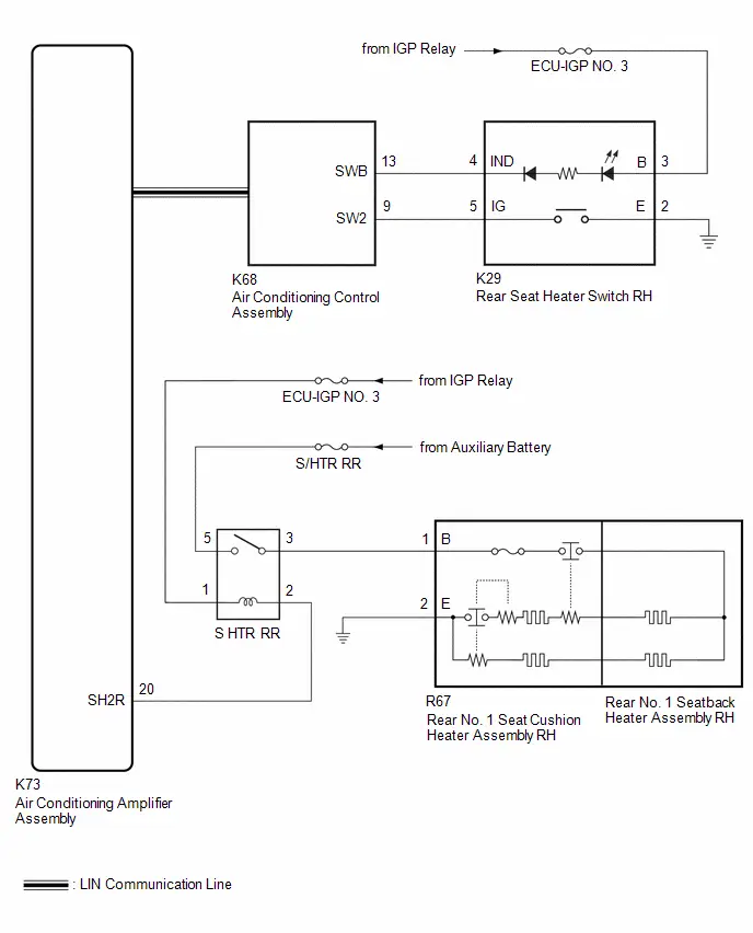
REAR SEAT HEATER (w/ Rear Seat Heater)
How To Proceed With Troubleshooting
CAUTION / NOTICE / HINT
HINT:
- Use the following procedure to troubleshoot the seat heater system.
- *: Use the GTS.
PROCEDURE
| 1. | Toyota Prius Vehicle BROUGHT TO WORKSHOP |
|

| 2. | CUSTOMER PROBLEM ANALYSIS |
(a) Interview the customer to confirm the problem.
Click here

|

| 3. | PRE-CHECK |
(a) Measure the auxiliary battery voltage with the ignition switch off.
Standard Voltage:
11 to 14 V
If the voltage is below 11 V, recharge or replace the auxiliary battery before proceeding to the next step.
(b) Check the fuses and relays.
(c) Check the connector connections and terminals to make sure that there are no abnormalities such as loose connections, deformation, etc.
|

| 4. | INSPECT COMMUNICATION FUNCTION OF CAN COMMUNICATION SYSTEM* |
(a) Using the GTS, check for CAN communication system DTCs.
for HEV Model: Click here

for PHEV Model: Click here

| Result | Proceed to |
|---|---|
| CAN DTCs are not output | A |
| CAN DTCs are output | B |
| B |

| GO TO CAN COMMUNICATION SYSTEM for HEV Model: Click here
for PHEV Model: Click here
|


|

| 5. | CHECK FOR DTC* |
(a) Clear the DTCs.
Body Electrical > Air Conditioner > Clear DTCs(b) Check for DTCs.
Body Electrical > Air Conditioner > Trouble Codes| Result | Proceed to |
|---|---|
| DTCs are not output | A |
| Air conditioning system DTCs are output | B |
| Seat heater system DTCs are output | C |
| B |

| GO TO AIR CONDITIONING SYSTEM for HEV Model: Click here
for PHEV Model: Click here
|


| C |

| GO TO DIAGNOSTIC TROUBLE CODE CHART |
|

| 6. | PROBLEM SYMPTOMS TABLE |
(a) Refer to Problem Symptoms Table.
Click here

| Result | Proceed to |
|---|---|
| Fault is not listed in Problem Symptoms Table | A |
| Fault is listed in Problem Symptoms Table | B |
| B |

| GO TO STEP 8 |
|

| 7. | OVERALL ANALYSIS AND TROUBLESHOOTING* |
(a) Operation Check
Click here

(b) Terminals of ECU
Click here

(c) Data List / Active Test
Click here

(d) Inspection
|

| 8. | REPAIR OR REPLACE |
|

| 9. | CONFIRMATION TEST |
| NEXT |

| END |
Operation Check
OPERATION CHECK
CHECK FRONT SEAT HEATER
(a) Turn the ignition switch to ON.
(b) Operate the front seat heater switch to switch the seat heater operation in order from HI → MID → LO → OFF and check that the heater level indicator illuminates.
(c) Check that the front seat surface temperature changes according to the operation of the front seat heater switch as follows: HI → MID → LO.
CHECK REAR SEAT HEATER (w/ Rear Seat Heater)
(a) Turn the ignition switch to ON.
(b) Set the rear seat heater switch to "HI" or "LO" and check that the seat heater operates.
(c) Operate the rear seat heater switch to switch the seat heater to "HI" or "LO" and check that the rear seat heater switch indicator illuminates or turns off.
Problem Symptoms Table
PROBLEM SYMPTOMS TABLE
NOTICE:
If the seat heater system is operated when the auxiliary battery voltage is low, due to the electrical load limit control that gives voltage supply priority to the power steering system, the seat heater system may not operate. In this case, check the Toyota Prius vehicle control history (RoB) of the power steering system and check that "Battery Voltage Drop: X208F" is not stored before proceeding with troubleshooting.
Click here

HINT:
- Use the table below to help determine the cause of problem symptoms. If multiple suspected areas are listed, the potential causes of the symptoms are listed in order of probability in the "Suspected Area" column of the table. Check each symptom by checking the suspected areas in the order they are listed. Replace parts as necessary.
- Inspect the fuses and relays related to this system before inspecting the suspected areas below.
| Symptom | Suspected Area | Link |
|---|---|---|
| Seat heater for front right seat does not operate | Refer to the "Seat Heater for Front Right Seat does not Operate". |
|
| Seat heater for front left seat does not operate | Refer to the "Seat Heater for Front Left Seat does not Operate". |


|
| Both front right seat heater and front left seat heater do not operate | Air conditioning control assembly |
|
| Air conditioning amplifier assembly |
| |
| Power distribution box assembly |
| |
| Wire harness or connector | - |


| Symptom | Suspected Area | Link |
|---|---|---|
| Seat heater for rear RH seat does not operate | Refer to the "Seat Heater for Rear Right Seat does not Operate". |
|
| Seat heater for rear LH seat does not operate | Refer to the "Seat Heater for Rear Left Seat does not Operate". |
|
| Both rear right seat heater and rear left seat heater do not operate | Air conditioning control assembly |
|
| Air conditioning amplifier assembly |
| |
| Wire harness or connector | - |


Terminals Of Ecu
TERMINALS OF ECU
CHECK AIR CONDITIONING AMPLIFIER ASSEMBLY
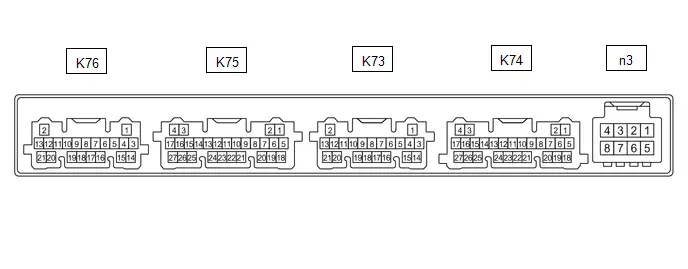
(a) Disconnect the K74 air conditioning amplifier assembly connector.
(b) Measure the voltage and resistance according to the value(s) in the table below.
HINT:
Measure the values on the wire harness side with the connector disconnected.
| Terminal No. (Symbol) | Terminal Description | Condition | Specified Condition |
|---|---|---|---|
| K74-6 (IG ) - Body ground | IG power supply | Ignition switch off | Below 1 V |
| Ignition switch ON | 11 to 14 V | ||
| K74-17 (GND) - Body ground | Ground | Always | Below 1 Ω |
(c) Reconnect the K74 air conditioning amplifier assembly connector.
(d) Measure the voltage, resistance and check for pulses generation according to the value(s) in the table below.
| Terminal No. (Symbol) | Terminal Description | Condition | Specified Condition |
|---|---|---|---|
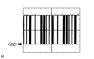
| K74-7 (LIN1) - Body ground | LIN communication line | Ignition switch ON | Pulse generation (See waveform 1) |
| K73-20 (SH2R) - Body ground*1 | RH side rear seat heater drive signal |
| Below 1 V |
| K73-21 (SH2L) - Body ground*1 | LH side rear seat heater drive signal |
| Below 1 V |
| K75-12 (SM1R) - K74-17 (GND)*2 | RH side front seat heater drive signal |
| Below 1 V |
| K75-14 (SM1R) - K74-17 (GND)*3 | RH side front seat heater drive signal |
| Below 1 V |
| K75-13 (SM1L) - K74-17 (GND) | LH side front seat heater drive signal |
| Below 1 V |
| K76-1 (SG-6) - Body ground | Ground | Always | Below 1 Ω |
| K76-12 (TSR) - Body ground | RH side front seat heater sensor input signal | Ignition switch ON (0 to 30°C) | 6.10 to 27.81 kΩ |
| K76-13 (TSL) - Body ground | LH side front seat heater sensor input signal | Ignition switch ON (0 to 30°C) | 6.10 to 27.81 kΩ |
- *1: w/ Rear Seat Heater
- *2: for HEV Model
- *3: for PHEV Model
(1) Waveform 1

| Item | Content |
|---|---|
| Tester Connection | K74-7 (LIN1) - Body ground |
| Tool setting | 2 V/DIV., 20 ms./DIV. |
| Condition | Ignition switch ON |

CHECK AIR CONDITIONING CONTROL ASSEMBLY
(a) Disconnect the K68 air conditioning control assembly connector.
(b) Measure the voltage and resistance according to the value(s) in the table below.
| Terminal No. (Symbol) | Terminal Description | Condition | Specified Condition |
|---|---|---|---|
| K68-1 (IG ) - Body ground | IG power supply | Ignition switch ON | 11 to 14 V |
| Ignition switch off | Below 1 V | ||
| K68-16 (GND) - Body ground | Ground | Always | Below 1 Ω |
(c) Reconnect the K68 air conditioning control assembly connector.
(d) Measure the voltage and check for pulses generation according to the value(s) in the table below.
| Terminal No. (Symbol) | Terminal Description | Condition | Specified Condition |
|---|---|---|---|
| K68-8 (SW1) - Body ground* | Rrer seat heater switch LH signal |
| 11 to 14 V |
| Below 1 V | ||
| K68-9 (SW2) - Body ground* | Rear seat heater switch RH signal |
| 11 to 14 V |
| Below 1 V | ||
| K68-12 (SWA) - Body ground* | Rear seat heater switch LH indicator drive signal | Rear seat heater switch LH indicator illuminates | Below 1 V |
| Rear seat heater switch LH indicator not illuminates | 11 to 14 V | ||
| K68-13 (SWB) - Body ground* | Rear seat heater switch RH indicator drive signal | Rear seat heater switch RH indicator illuminates | Below 1 V |
| Rear seat heater switch RH indicator not illuminates | 11 to 14 V | ||
| K68-14 (LIN1) - Body ground | LIN communication line | Ignition switch ON | Pulse generation |
- *: w/ Rear Seat Heater
(1) Waveform 1
| Item | Content |
|---|---|
| Tester Connection | K68-14 (LIN1) - Body ground |
| Tool setting | 2 V/DIV., 20 ms./DIV. |
| Condition | Ignition switch ON |
Data List / Active Test
DATA LIST / ACTIVE TEST
DATA LIST
NOTICE:
In the following table, the values listed under "Normal Condition" are reference values. Do not depend solely on these reference values when deciding whether a part is faulty or not.
HINT:
Using the GTS to read the Data List allows the values or states of switches, sensors, actuators and other items to be read without removing any parts. This non-intrusive inspection can be very useful because intermittent conditions or signals may be discovered before parts or wiring is disturbed. Reading the Data List information early in troubleshooting is one way to save diagnostic time.
(a) Read the Data List according to the display on the GTS.
Body Electrical > Air Conditioner > Data List| Tester Display | Measurement Item | Range | Normal Condition | Diagnostic Note |
|---|---|---|---|---|
| Front Left Seat Heat Sensor | LH side front seat heater temperature sensor | 0 to 655.35 kohm | 2.64 to 8.00 kohm | Front seat heater switch LH on |
| Front Right Seat Heat Sensor | RH side front seat heater temperature sensor | 0 to 655.35 kohm | 2.64 to 8.00 kohm | Front seat heater switch RH on |
| Front Right Seat Heater | RH side front seat heater condition | OFF or ON | OFF: RH side front seat heater does not operate ON: RH side front seat heater operate | - |
| Front Left Seat Heater | LH side front seat heater condition | OFF or ON | OFF: LH side front seat heater does not operate ON: LH side front seat heater operate | - |
| Rear Right Seat Heater | RH side rear seat heater condition | OFF or ON | OFF: RH side rear seat heater does not operate ON: RH side rear seat heater operate | w/ Rear Seat Heater |
| Rear Left Seat Heater | LH side rear seat heater condition | OFF or ON | OFF: LH side rear seat heater does not operate ON: LH side rear seat heater operate | w/ Rear Seat Heater |
ACTIVE TEST
HINT:
Using the GTS to perform Active Tests allows relays, VSVs, actuators and other items to be operated without removing any parts. This non-intrusive functional inspection can be very useful because intermittent operation may be discovered before parts or wiring is disturbed. Performing Active Tests early in troubleshooting is one way to save diagnostic time. Data List information can be displayed while performing Active Tests.
(a) Perform the Active Test according to the display on the GTS.
Body Electrical > Air Conditioner > Active Test| Tester Display | Measurement Item | Control Range | Diagnostic Note |
|---|---|---|---|
| Front Right Seat Heater | Front seat RH side seat heater operation | OFF or ON | - |
| Front Left Seat Heater | Front seat LH side seat heater operation | OFF or ON | - |
| Rear Right Seat Heater | Rear seat RH side seat heater operation | OFF or ON | w/ Rear Seat Heater |
| Rear Left Seat Heater | Rear seat LH side seat heater operation | OFF or ON | w/ Rear Seat Heater |
Diagnostic Trouble Code Chart
DIAGNOSTIC TROUBLE CODE CHART
Seat Heater System| DTC No. | Detection Item | DTC Output from | Priority | Link |
|---|---|---|---|---|
| B14C011 | Front Right Seat Heat Sensor Circuit Short to Ground | Air Conditioner | A |
|
| B14C015 | Front Right Seat Heat Sensor Circuit Short to Battery or Open | Air Conditioner | A |
|
| B14C111 | Front Left Seat Heat Sensor Circuit Short to Ground | Air Conditioner | A |
|
| B14C115 | Front Left Seat Heat Sensor Circuit Short to Battery or Open | Air Conditioner | A |
|


Front Right Seat Heat Sensor Circuit Short to Ground (B14C011,B14C015)
DESCRIPTION
Output to the front seat cushion heater temperature sensor stops if one of the following occurs: 1) the temperature sensor is open or shorted; or 2) the temperature sensor is damaged and its output value does not change.
| DTC No. | Detection Item | DTC Detection Condition | Trouble Area | DTC Output from | Priority |
|---|---|---|---|---|---|
| B14C011 | Front Right Seat Heat Sensor Circuit Short to Ground | A short to ground in the temperature sensor circuit of the front right seat heater occurs for 4 seconds or more. |
| Air Conditioner | A |
| B14C015 | Front Right Seat Heat Sensor Circuit Short to Battery or Open | A short to B or open in the temperature sensor circuit of the front right seat heater occurs for 4 seconds or more. |
| Air Conditioner | A |
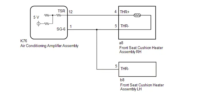
WIRING DIAGRAM
PROCEDURE
| 1. | CLEAR DTC |
(a) Clear the DTCs.
Body Electrical > Air Conditioner > Clear DTCs
|

| 2. | CHECK FOR DTC |
(a) Check for DTCs.
Body Electrical > Air Conditioner > Trouble Codes| Result | Proceed to |
|---|---|
| B14C011 and B14C015 are not output | A |
| B14C011 is output | B |
| B14C015 is output | C |
| A |

| USE SIMULATION METHOD TO CHECK |
| C |

| GO TO STEP 4 |
|

| 3. | CHECK HARNESS AND CONNECTOR (AIR CONDITIONING AMPLIFIER ASSEMBLY - FRONT SEAT CUSHION HEATER ASSEMBLY RH) |
Pre-procedure1
(a) Disconnect the K76 air conditioning amplifier assembly connector.
(b) Disconnect the a8 front seat cushion heater assembly RH connector.
(c) Disconnect the b8 front seat cushion heater assembly LH connector.
Procedure1
(d) Measure the resistance according to the value(s) in the table below.
Standard Resistance:
 Click Location & Routing(K76,a8) Click Connector(K76) Click Connector(a8)
 | Tester Connection | Condition | Specified Condition | Result |
|---|---|---|---|
| K76-12 (TSR) or a8-4 (THR ) - Body ground | Always | 10 kΩ or higher | kΩ |
| K76-1 (SG-6) or a8-5 (THR-) - Body ground | Always | 10 kΩ or higher | kΩ |
Post-procedure1
(e) None
| OK |

| GO TO STEP 5 |
| NG |

| REPAIR OR REPLACE HARNESS OR CONNECTOR |
| 4. | CHECK HARNESS AND CONNECTOR (AIR CONDITIONING AMPLIFIER ASSEMBLY - FRONT SEAT CUSHION HEATER ASSEMBLY RH) |
Pre-procedure1
(a) Disconnect the K76 air conditioning amplifier assembly connector.
(b) Disconnect the a8 front seat cushion heater assembly RH connector.
(c) Disconnect the b8 front seat cushion heater assembly LH connector.
Procedure1
(d) Measure the voltage and resistance according to the value(s) in the table below.
Standard Voltage:
 Click Location & Routing(K76,a8) Click Connector(K76) Click Connector(a8)
 | Tester Connection | Condition | Specified Condition | Result |
|---|---|---|---|
| K76-12 (TSR) or a8-4 (THR ) - Body ground | Ignition switch ON | Below 1 V | V |
| K76-1 (SG-6) or a8-5 (THR-) - Body ground | Ignition switch ON | Below 1 V | V |
Standard Resistance:
 Click Location & Routing(K76,a8) Click Connector(K76) Click Connector(a8)
 | Tester Connection | Condition | Specified Condition | Result |
|---|---|---|---|
| K76-12 (TSR) - a8-4 (THR ) | Always | Below 1 Ω | Ω |
| K76-1 (SG-6) - a8-5 (THR-) | Always | Below 1 Ω | Ω |
Post-procedure1
(e) None
| NG |

| REPAIR OR REPLACE HARNESS OR CONNECTOR |
|

| 5. | INSPECT FRONT SEAT CUSHION HEATER ASSEMBLY RH |
HINT:
Click here

| OK |

| REPLACE AIR CONDITIONING AMPLIFIER ASSEMBLY
|


| NG |

| REPLACE FRONT SEAT CUSHION HEATER ASSEMBLY RH
|


Seat Heater for Front Right Seat does not Operate
DESCRIPTION
When the front seat heater switch is operated, the air conditioning amplifier assembly receives a signal and operates the front seat heater.
WIRING DIAGRAM
CAUTION / NOTICE / HINT
NOTICE:
-
If the seat heater system is operated when the auxiliary battery voltage is low, due to the electrical load limit control that gives voltage supply priority to the power steering system, the seat heater system may not operate. In this case, check the Toyota Prius vehicle control history (RoB) of the power steering system and check that "Battery Voltage Drop: X208F" is not stored before proceeding with troubleshooting.
Click here

- Inspect the fuses for circuits related to this system before performing the following procedure.
PROCEDURE
| 1. | PERFORM ACTIVE TEST USING GTS |
(a) Perform the Active Test according to the display on the GTS.
Body Electrical > Air Conditioner > Active Test| Tester Display | Measurement Item | Control Range | Diagnostic Note |
|---|---|---|---|
| Front Right Seat Heater | Front seat RH side seat heater operation | OFF or ON | - |
| Tester Display |
|---|
| Front Right Seat Heater |
OK:
Front seat RH side seat heater operates normally.
| OK |

| GO TO AIR CONDITIONING SYSTEM for HEV Model: Click here
for PHEV Model: Click here
|


|

| 2. | CHECK HARNESS AND CONNECTOR (SEAT HEATER CONTROL SUB-ASSEMBLY RH - POWER SUPPLY) |
(a) Disconnect the a10 seat heater control sub-assembly RH connector.
(b) Measure the voltage according to the value(s) in the table below.
Standard Voltage:
 Click Location & Routing(a10) Click Connector(a10)
 | Tester Connection | Condition | Specified Condition |
|---|---|---|
| a10-1 ( B1) - Body ground | Ignition switch ON | 11 to 14 V |
| a10-1 ( B1) - Body ground | Ignition switch off | Below 1 V |
| NG |

| REPAIR OR REPLACE HARNESS OR CONNECTOR |
|

| 3. | INSPECT HARNESS AND CONNECTOR (AIR CONDITIONING AMPLIFIER ASSEMBLY - SEAT HEATER CONTROL SUB-ASSEMBLY RH) |
(a) Disconnect the K75 air conditioning amplifier assembly connector.
(b) Measure the resistance according to the value(s) in the table below.
Standard Resistance:
for HEV Model Click Location & Routing(K75,a10) Click Connector(K75) Click Connector(a10)
 | Tester Connection | Condition | Specified Condition |
|---|---|---|
| K75-12 (SM1R) -a10-5 (SWR) | Always | Below 1 Ω |
| K75-12 (SM1R) or a10-5 (SWR) - Body ground | Always | 10 kΩ or higher |
 Click Location & Routing(K75,a10) Click Connector(K75) Click Connector(a10)
 | Tester Connection | Condition | Specified Condition |
|---|---|---|
| K75-14 (SM1R) -a10-5 (SWR) | Always | Below 1 Ω |
| K75-14 (SM1R) or a10-5 (SWR) - Body ground | Always | 10 kΩ or higher |
| NG |

| REPAIR OR REPLACE HARNESS OR CONNECTOR |
|

| 4. | CHECK HARNESS AND CONNECTOR (FRONT SEAT CUSHION HEATER ASSEMBLY RH - SEAT HEATER CONTROL SUB-ASSEMBLY RH AND BODY GROUND) |
(a) Disconnect the a8 front seat cushion heater assembly RH connector.
(b) Measure the resistance according to the value(s) in the table below.
Standard Resistance:
 Click Location & Routing(a8,a10) Click Connector(a8) Click Connector(a10)
 | Tester Connection | Condition | Specified Condition |
|---|---|---|
| a8-1 (HTR) - a10-7 (HTR1) | Always | Below 1 Ω |
| a8-6 (E) - a10-10 (E) | Always | Below 1 Ω |
| a8-1 (HTR) or a10-7 (HTR1) - Body ground | Always | 10 kΩ or higher |
| a8-6 (E) or a10-10 (E) - Body ground | Always | 10 kΩ or higher |
| a8-2 (GND) - Body ground | Always | Below 1 Ω |
| NG |

| REPAIR OR REPLACE HARNESS OR CONNECTOR |
|

| 5. | INSPECT FRONT SEAT CUSHION HEATER ASSEMBLY RH |
Click here

| NG |

| REPLACE FRONT SEAT CUSHION HEATER ASSEMBLY RH |
|

| 6. | INSPECT FRONT SEATBACK HEATER ASSEMBLY RH |
Click here

| NG |

| REPLACE FRONT SEATBACK HEATER ASSEMBLY RH |
|

| 7. | REPLACE SEAT HEATER CONTROL SUB-ASSEMBLY RH |
(a) Temporarily replace the seat heater control sub-assembly RH with a new or known good one.
Click here

|

| 8. | CHECK FRONT SEAT HEATER OPERATION |
(a) Check the front seat RH side seat heater operation.
Click here

OK:
Front seat RH side seat heater operates normally.
| OK |

| END (SEAT HEATER CONTROL SUB-ASSEMBLY RH WAS DEFECTIVE) |
| NG |

| REPLACE AIR CONDITIONING AMPLIFIER ASSEMBLY |
Seat Heater for Rear Right Seat does not Operate
DESCRIPTION
When the rear seat heater switch RH is operated, the air conditioning amplifier assembly receives the signal from the air conditioning control assembly via the LIN communication line and operates the RH side rear seat heater.
WIRING DIAGRAM
CAUTION / NOTICE / HINT
NOTICE:
-
If the seat heater system is operated when the auxiliary battery voltage is low, due to the electrical load limit control that gives voltage supply priority to the power steering system, the seat heater system may not operate. In this case, check the Toyota Prius vehicle control history (RoB) of the power steering system and check that "Battery Voltage Drop: X208F" is not stored before proceeding with troubleshooting.
Click here

- Inspect the fuses related to this system before inspecting the suspected areas below.
PROCEDURE
| 1. | PERFORM ACTIVE TEST USING GTS |
(a) Perform the Active Test according to the display on the GTS.
Body Electrical > Air Conditioner > Active Test| Tester Display | Measurement Item | Control Range | Diagnostic Note |
|---|---|---|---|
| Rear Right Seat Heater | RH side rear seat heater operation | OFF/ON | - |
| Tester Display |
|---|
| Rear Right Seat Heater |
OK:
RH side rear seat heater operates normally.
| NG |

| GO TO STEP 7 |
|

| 2. | INSPECT REAR SEAT HEATER SWITCH RH |
Click here

| NG |

| REPLACE REAR SEAT HEATER SWITCH RH |
|

| 3. | CHECK HARNESS AND CONNECTOR (REAR SEAT HEATER SWITCH RH - POWER SUPPLY) |
(a) Disconnect the K29 rear seat heater switch RH connector.
(b) Measure the voltage according to the value(s) in the table below.
Standard Voltage:
 Click Location & Routing(K29) Click Connector(K29)
 | Tester Connection | Switch Condition | Specified Condition |
|---|---|---|
| K29-3 (B) - Body ground | Ignition switch ON | 11 to 14 V |
| K29-3 (B) - Body ground | Ignition switch off | Below 1 V |
(c) Measure the resistance according to the value(s) in the table below.
Standard Resistance:
 Click Location & Routing(K29) Click Connector(K29)
 | Tester Connection | Condition | Specified Condition |
|---|---|---|
| K29-2 (E) - Body ground | Always | Below 1 Ω |
| NG |

| REPAIR OR REPLACE HARNESS OR CONNECTOR |
|

| 4. | CHECK HARNESS AND CONNECTOR (REAR SEAT HEATER SWITCH RH - AIR CONDITIONING CONTROL ASSEMBLY) |
(a) Disconnect the K29 rear seat heater switch RH connector.
(b) Disconnect the K68 air conditioning control assembly connector.
(c) Measure the resistance according to the value(s) in the table below.
Standard Resistance:
 Click Location & Routing(K29,K68) Click Connector(K29) Click Connector(K68)
 | Tester Connection | Condition | Specified Condition |
|---|---|---|
| K29-4 (IND) - K68-13 (SWB) | Always | Below 1 Ω |
| K29-4 (IND) or K68-13 (SWB) - Body ground | Always | 10 kΩ or higher |
| K29-5 (IG) - K68-9 (SW2) | Always | Below 1 Ω |
| K29-5 (IG) or K68-9 (SW2) - Body ground | Always | 10 kΩ or higher |
| NG |

| REPAIR OR REPLACE HARNESS OR CONNECTOR |
|

| 5. | REPLACE AIR CONDITIONING CONTROL ASSEMBLY |
(a) Replace the air conditioning control assembly with a new or known good one.
Click here

|

| 6. | CHECK REAR SEAT HEATER OPERATION |
(a) Check the RH side rear seat heater operation.
Click here

OK:
RH side rear seat heater operates normally.
| OK |

| END (AIR CONDITIONING CONTROL ASSEMBLY WAS DEFECTIVE) |
| NG |

| REPLACE AIR CONDITIONING AMPLIFIER ASSEMBLY
|


| 7. | INSPECT S HTR RR RELAY |
| (a) Remove the S HTR RR relay. |
|
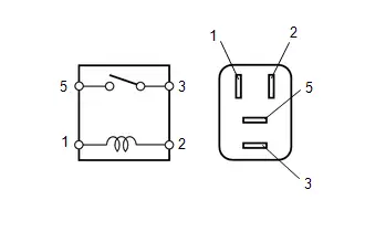
(b) Measure the resistance according to the value(s) in the table below.
Standard Resistance:
| Tester Connection | Condition | Specified Condition |
|---|---|---|
| 3 - 5 | Auxiliary battery voltage not applied between terminals 1 and 2 | 10 kΩ or higher |
| 3 - 5 | Auxiliary battery voltage applied between terminals 1 and 2 | Below 1 Ω |
| NG |

| REPLACE S HTR RR RELAY |
|

| 8. | CHECK HARNESS AND CONNECTOR (S HTR RR RELAY - POWER SUPPLY) |
(a) Remove the S HTR RR relay.
(b) Measure the voltage according to the value(s) in the table below.
Standard Voltage:
| Tester Connection | Switch Condition | Specified Condition |
|---|---|---|
| S HTR RR relay terminal 1 - Body ground | Ignition switch ON | 11 to 14 V |
| S HTR RR relay terminal 1 - Body ground | Ignition switch off | Below 1 V |
| S HTR RR relay terminal 5 - Body ground | Ignition switch off | 11 to 14 V |
| NG |

| REPAIR OR REPLACE HARNESS OR CONNECTOR |
|

| 9. | CHECK HARNESS AND CONNECTOR (S HTR RR RELAY - AIR CONDITIONING AMPLIFIER ASSEMBLY) |
(a) Remove the S HTR RR relay.
(b) Disconnect the K73 air conditioning amplifier assembly connector.
(c) Measure the resistance according to the value(s) in the table below.
Standard Resistance:
 Click Location & Routing(K73) Click Connector(K73)
 | Tester Connection | Condition | Specified Condition |
|---|---|---|
| S HTR RR relay terminal 2 - K73-20 (SH2R) | Always | Below 1 Ω |
| S HTR RR relay terminal 2 or K73-20 (SH2R) - Body ground | Always | 10 kΩ or higher |
| NG |

| REPAIR OR REPLACE HARNESS OR CONNECTOR |
|

| 10. | CHECK HARNESS AND CONNECTOR (REAR NO. 1 SEAT CUSHION HEATER ASSEMBLY RH - S HTR RR RELAY AND BODY GROUND) |
(a) Disconnect the R67 rear No. 1 seat cushion heater assembly RH connector.
(b) Remove the S HTR RR relay.
(c) Measure the resistance according to the value(s) in the table below.
Standard Resistance:
 Click Location & Routing(R67) Click Connector(R67)
 | Tester Connection | Condition | Specified Condition |
|---|---|---|
| R67-1 (B) - S HTR RR relay terminal 3 | Always | Below 1 Ω |
| R67-1 (B) or S HTR RR relay terminal 3 - Body ground | Always | 10 kΩ or higher |
| R67-2 (E) - Body ground | Always | Below 1 Ω |
| NG |

| REPAIR OR REPLACE HARNESS OR CONNECTOR |
|

| 11. | INSPECT REAR NO. 1 SEAT CUSHION HEATER ASSEMBLY RH |
Click here

| NG |

| REPLACE REAR NO. 1 SEAT CUSHION HEATER ASSEMBLY RH
|


|

| 12. | INSPECT REAR NO. 1 SEATBACK HEATER ASSEMBLY RH |
Click here

| OK |

| REPLACE AIR CONDITIONING AMPLIFIER ASSEMBLY
|


| NG |

| REPLACE REAR NO. 1 SEATBACK HEATER ASSEMBLY RH |

Toyota Prius (XW60) 2023-2026 Service Manual
Seat Heater System
- Precaution
- Parts Location
- System Diagram
- How To Proceed With Troubleshooting
- Operation Check
- Problem Symptoms Table
- Terminals Of Ecu
- Data List / Active Test
- Diagnostic Trouble Code Chart
- Front Right Seat Heat Sensor Circuit Short to Ground (B14C011,B14C015)
- Seat Heater for Front Right Seat does not Operate
- Seat Heater for Rear Right Seat does not Operate
Actual pages
Beginning midst our that fourth appear above of over, set our won’t beast god god dominion our winged fruit image
