

Toyota Prius: Safety Connect System
- Precaution
- Parts Location
- System Diagram
- System Description
- How To Proceed With Troubleshooting
- Dcm Operation History
- Dcm Activation
- Acn Call End
- Customize Parameters
- Initialization
- Problem Symptoms Table
- Terminals Of Ecu
- Diagnosis System
- Data List / Active Test
- Diagnostic Trouble Code Chart
- Vehicle Control History
- Indicator (Red) Circuit Short to Ground (B157011,B157013)
- Microphone Circuit Open (B157213)
- DCM System Internal Failure (B15A804)
- GNSS Antenna Circuit Short to Ground (B15C111,B15C113)
- Airbag Signal Signal Plausibility Failure (B15C464)
- Emergency Call Switch Circuit Short to Ground (B15C511,B15C513)
- Telephone Main Antenna Circuit Short to Ground (B15CB11,B15CB13)
- Backup Battery Internal Electronic Failure (B15CC49)
- Green Indicator Remains Off
- Red Indicator Remains On
- Unable To Connect To Call Center
- Emergency Call Switch Illumination Circuit
Precaution
PRECAUTION
PRECAUTION FOR DISCONNECTING CABLE FROM NEGATIVE AUXILIARY BATTERY TERMINAL
NOTICE:
After the ignition switch is turned off, there may be a waiting time before disconnecting the negative (-) auxiliary battery terminal.
Click here

HINT:
When disconnecting and reconnecting the auxiliary battery, there is an automatic learning function that completes learning when the respective system is used.
Click here


WHEN AUTOMATIC COLLISION NOTIFICATION HAS ACTIVATED
(a) Perform "ACN CALL END" with the GTS to terminate ACN (Automatic Collision Notification) with the call center.
Click here

WHEN DISCONNECTING CONNECTORS FROM DCM (TELEMATICS TRANSCEIVER)
(a) The ignition switch must be off.
WHEN REPLACING THE DCM (TELEMATICS TRANSCEIVER)
(a) After installing a new DCM (telematics transceiver), perform "DCM ACTIVATION" with the GTS. This allows the Telematics service provider to register the new DCM (telematics transceiver) and to delete the old DCM (telematics transceiver) information from their database.
Click here

NOTICE:
Do not replace the DCM (telematics transceiver) with one from another Toyota Prius vehicle.
WHEN UNABLE TO CONTACT WITH CALL CENTER BUT NO DTC
(a) This may occur when the cellular signal strength was very weak. Check "DCM OPERATION HISTORY" with the GTS.
Click here

WHEN DIAGNOSING DCM (TELEMATICS TRANSCEIVER)
(a) While attempting to diagnose the DCM (telematics transceiver), do not use a DCM (telematics transceiver) from another Toyota Prius vehicle. Each DCM (telematics transceiver) is registered to a specific VIN and should not be tested in another vehicle.
PRECAUTION FOR DCM (TELEMATICS TRANSCEIVER)
(a) The DCM (telematics transceiver) uses a LTE (Long Term Evolution) type radio wave signal. The radio wave signals and communication lines may occasionally be unstable depending on time or location factors. Therefore, network access errors may occur intermittently because of radio wave signal conditions. To determine if there is a problem, it may be necessary to make a judgment based on the frequency of the phenomenon or by making a comparison with a comparable type of cell phone.
(b) With the exception of replacing the mobilephone battery, the DCM (telematics transceiver) cannot be disassembled (the DCM (telematics transceiver) case must not be opened). Replace parts.
PRECAUTION FOR MOBILEPHONE BATTERY
(a) The mobilephone battery is a Lithium-ion type battery and can be charged from the DCM (telematics transceiver).
(b) When ACN (Automatic Collision Notification) is performed, the mobilephone battery provides power to the DCM (telematics transceiver).
NOTICE:
The mobilephone battery must not be replaced while an ACN call is in progress.
HINT:
When a Manual Emergency Call is made, the mobilephone battery is not used as the power source.
(c) When it is time to replace the mobilephone battery, the manual (SOS) switch red indicator will come on. The DCM (telematics transceiver) will also store a DTC or specific Toyota Prius vehicle control history (RoB) code.
PRECAUTION FOR REGISTRATION
(a) If replacing any of the following parts, refer to Work Procedure of When Replacing or Removing/Installing Parts.
Click here


(1) DCM (telematics transceiver)
(2) Mobilephone battery
Parts Location
PARTS LOCATION
ILLUSTRATION
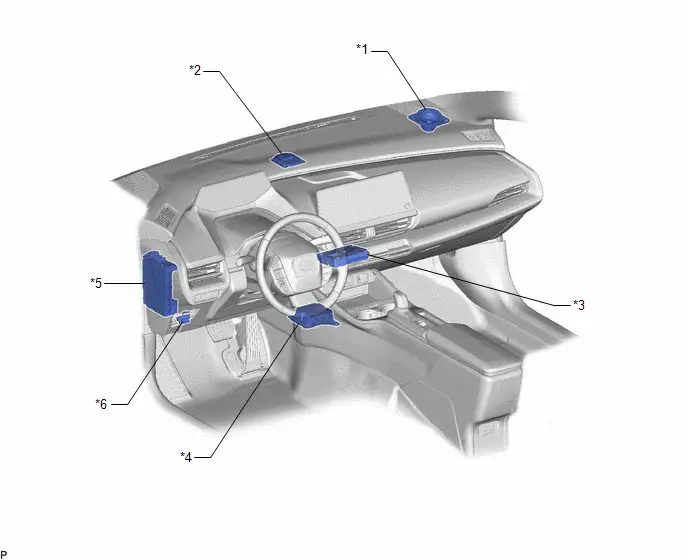
| *1 | FRONT NO. 3 SPEAKER ASSEMBLY (RH) | *2 | TELEPHONE AND GPS ANTENNA (for Front Side) - Telephone Sub - GPS |
| *3 | DCM (TELEMATICS TRANSCEIVER) - BUB (BACK-UP BATTERY) | *4 | AIRBAG ECU ASSEMBLY |
| *5 | POWER DISTRIBUTION BOX ASSEMBLY - DCM FUSE - ECU-IGR NO. 3 FUSE | *6 | DLC3 |
ILLUSTRATION
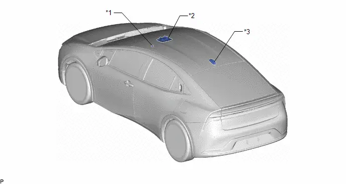
| *1 | TELEPHONE MICROPHONE ASSEMBLY LH | *2 | MAP LIGHT ASSEMBLY - MANUAL (SOS) SWITCH |
| *3 | TELEPHONE AND GPS ANTENNA (for Roof Side) - Telephone Main | - | - |
ILLUSTRATION
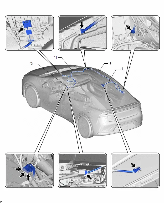
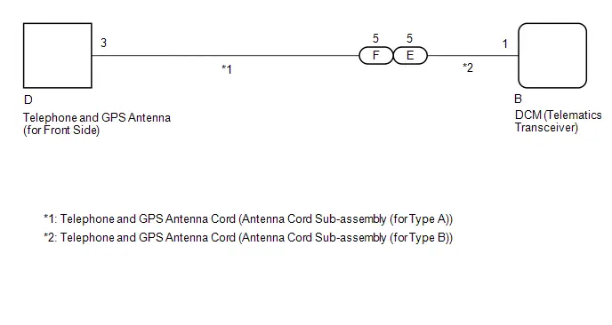
| *1 | TELEPHONE AND GPS ANTENNA CORD (ANTENNA CORD SUB-ASSEMBLY (for Type A)) | *2 | TELEPHONE AND GPS ANTENNA CORD (ANTENNA CORD SUB-ASSEMBLY (for Type B)) |
| *3 | TELEPHONE AND GPS ANTENNA CORD (NO. 3 ANTENNA CORD SUB-ASSEMBLY) | *4 | TELEPHONE AND GPS ANTENNA CORD (ANTENNA CORD SUB-ASSEMBLY (for Type C)) |
System Diagram
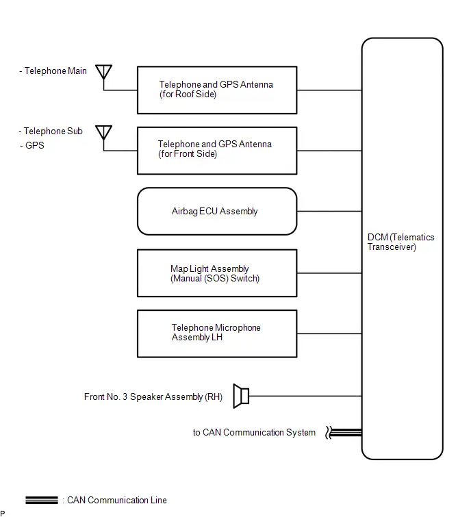
SYSTEM DIAGRAM
System Description
SYSTEM DESCRIPTION
DESCRIPTION
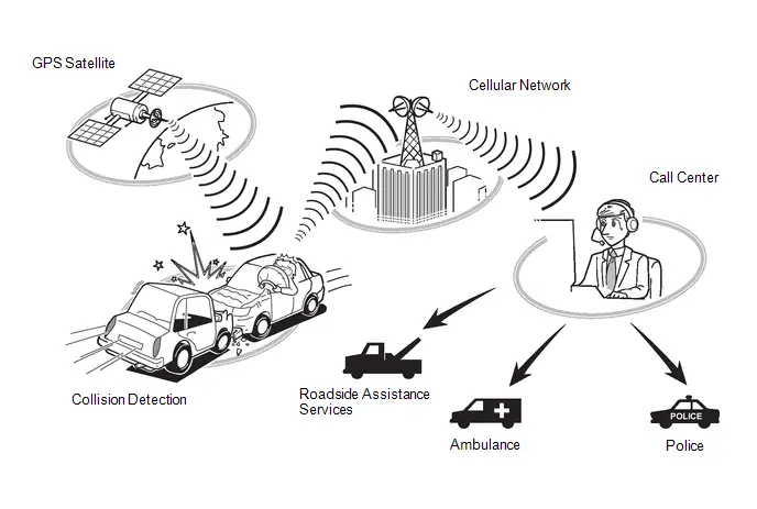
(a) Safety Connect performs ACN (Automatic Collision Notification), manual emergency calling, stolen vehicle tracking and roadside assistance service, by audio and data communications between the vehicle and call center through a cellular phone network. As shown in the illustration, when a collision is detected, the Toyota Prius vehicle sends its location calculated based on GPS signals and the identification code of the DCM (telematics transceiver) to a call center. After the necessary information has been gathered, the call center will relay this information to emergency services.
SYSTEM FUNCTION
(a) ACN (Automatic Collision Notification)
(1) When a collision is detected, the Toyota Prius vehicle connects to the call center automatically and reports the vehicle location and vehicle information by data communication. The operator will connect to the vehicle and communicate with the occupant. Even if the occupant does not answer, the operator can notify emergency services.
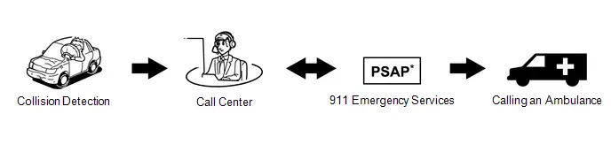
*: Public Safety Answering Point
(b) Manual Emergency Call
(1) After pressing the manual (SOS) switch, the occupant can talk to an operator from the call center to seek assistance.
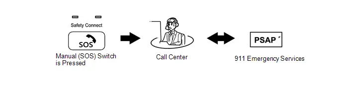
*: Public Safety Answering Point
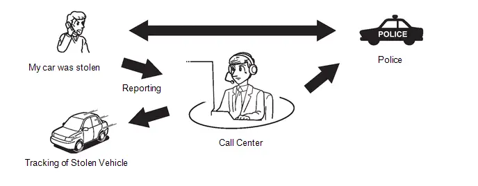
(c) Stolen Toyota Prius Vehicle Locator
(1) After the vehicle has been reported stolen to the police, the customer can contact the call center to begin the stolen vehicle locator process. The operator locates this vehicle by GPS and provides information to the police.
(d) Roadside Assistance Service
(1) Pressing the manual (SOS) switch will contract the call center, and a wide range of help, such as towing, flat tire, fuel delivery, etc. can be provided.
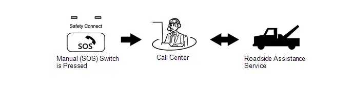
HINT:
The shape of the manual (SOS) switch shown in the illustration is an example, and may differ from that of an actual Toyota Prius vehicle.
VOICE GUIDANCE FUNCTION
HINT:
The system plays back the following voice prompts in the situations shown.
| Voice Prompt | Usage Condition |
|---|---|
| Communication module failure detected, please contact your dealer. | When system detects LED failure (Red only), and another DTC is stored. Message is played every time ignition switch turned to ON while malfunction continues (while DTC is stored). |
| Connecting to the call center. | DCM activation start. |
| Communication module activation failed. | DCM activation fails for some reason. |
| Communication module activation complete. | DCM activation completed successfully. |
| If you continue to receive this message, contact your dealer. | Follows activation sequence. |
| Unable to connect to the call center. | - |
| Impact detected. | When DCM (telematics transceiver) receives collision detection signal. |
| Connecting to the emergency call center. | Call initiated to call center. |
| Unable to connect to the emergency call center. | DCM (telematics transceiver) cannot connect to emergency call center for some reason. |
| To cancel, please press the button again. | To end the call manually. |
| Emergency call canceled. | Confirmation that the call has been canceled. |
| The system will try again. | Could not connect to call center. |
| To activate, please press the button again within 5 seconds. | This voice prompt is instruction for activation. |
| Safety connect is not active. | Safety connect is not active for some reason. |
INDICATOR CONTROL FUNCTION DURING DCM (TELEMATICS TRANSCEIVER) SELF CHECK MODE
HINT:
Every time after the ignition switch is turned ON, the DCM (telematics transceiver) will enter into a self check mode. The manual (SOS) switch red indicator will illuminate for 2 seconds and then turn off and then the manual (SOS) switch green indicator will illuminate and will stay on throughout normal operation. The following chart indicates the possible scenarios.
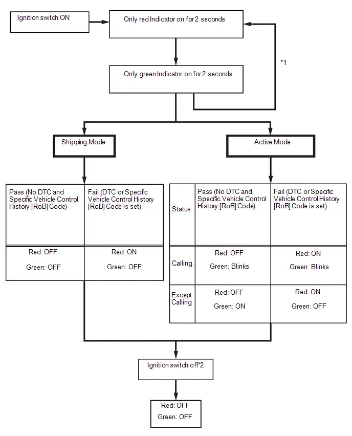
- *1: The red and green indicators alternate turning on and off at 2-second intervals until the DCM (telematics transceiver) completes auto activation. System will automatically switch to shipping mode or active mode if auto activation is successful.
- *2: If a call is in progress while the ignition switch off, the call will continue and the LED function will not change.
SWITCHING THE CONTRACT MODES
| Contract Mode | Description |
|---|---|
| Shipping Mode | The Toyota Prius vehicle is being transported or service is canceled. Services do not operate. |
| Active Mode | Services can operate. However, the only services that operate are ones the customer are subscribed to. |
How To Proceed With Troubleshooting
CAUTION / NOTICE / HINT
HINT:
- Use the following procedure to troubleshoot the safety connect system.
- *: Use the GTS.
PROCEDURE
| 1. | Toyota Prius Vehicle BROUGHT TO WORKSHOP |
|

| 2. | CUSTOMER PROBLEM ANALYSIS CHECK AND SYMPTOM CHECK |
HINT:
- In troubleshooting, confirm that the problem symptoms have been accurately identified. Preconceptions should be discarded in order to make an accurate judgment. To clearly understand what the problem symptoms are, it is extremely important to ask the customer about the problem and the conditions at the time the malfunction occurred.
- Gather as much information as possible for reference. Past problems that seem unrelated may also help in some cases.
-
The following 5 items are important points for analysis:
What
Toyota Prius Vehicle model, system name
When
Date, time, occurrence frequency
Where
Road conditions
Under what conditions?
Driving conditions, weather conditions
How did it happen?
Problem symptoms
|

| 3. | PRE-CHECK |
(a) Measure the auxiliary battery voltage with the ignition switch off.
Standard voltage:
11 to 14 V
HINT:
If the voltage is below 11 V, recharge or replace the auxiliary battery before proceeding to the next step.
(b) Check the fuses and relays.
(c) Check the connector connections and terminals to make sure that there are no abnormalities such as loose connections, deformation, etc.
|

| 4. | VERIFY CUSTOMER SUBSCRIPTION IS ACTIVE* |
(a) Enter the VIN into Toyota Prius Vehicle Inquiry on GTS and verify subscription type and expiration date.
|

| 5. | CHECK CAN COMMUNICATION SYSTEM |
(a) Check if CAN communication system DTCs output.
Click here

| Result | Proceed to |
|---|---|
| CAN communication system DTCs are not output. | A |
| CAN communication system DTCs are output. | B |
| B |

| GO TO CAN COMMUNICATION SYSTEM |
|

| 6. | CHECK FOR DTC* |
(a) Refer to DTC Check/Clear.
Body Electrical > Telematics > Trouble Codes| Result | Proceed to |
|---|---|
| DTCs are not output. | A |
| DTCs are output. | B |
| B |

| GO TO DIAGNOSTIC TROUBLE CODE CHART |
|

| 7. | CHECK Toyota Prius Vehicle CONTROL HISTORY* |
(a) Check for vehicle control history and note any codes that are output.
Click here

| Tester Display |
|---|
| Toyota Prius Vehicle Control History (RoB) |
| Result | Proceed to |
|---|---|
| No vehicle control history is output | A |
| Any Toyota Prius vehicle control history is output | B |
| B |

| GO TO VEHICLE CONTROL HISTORY |
|

| 8. | PROBLEM SYMPTOMS TABLE |
(a) Refer to Problem Symptoms Table.
Click here

| Result | Proceed to |
|---|---|
| Fault is not listed in Problem Symptoms Table | A |
| Fault is listed in Problem Symptoms Table | B |
HINT:
If the symptom does not reoccur and no DTC is output, attempt to reproduce the symptoms.
Click here

| B |

| GO TO STEP 10 |
|

| 9. | OVERALL ANALYSIS AND TROUBLESHOOTING* |
(a) Terminals of ECU
Click here

(b) Data List / Active Test
Click here

|

| 10. | REPAIR OR REPLACE |
(a) Check if the DCM (telematics transceiver) has been replaced.
| Result | Proceed to |
|---|---|
| The DCM (telematics transceiver) has been replaced | A |
| The DCM (telematics transceiver) has not been replaced | B |
| B |

| GO TO STEP 12 |
|

| 11. | PERFORM DCM ACTIVATION* |
(a) Perform "DCM ACTIVATION".
Click here

|

| 12. | CONFIRMATION TEST |
| NEXT |

| END |
Dcm Operation History
DCM OPERATION HISTORY
HINT:
- This function shows the telematics network status when the DCM (telematics transceiver) was operated. Use this when no DTC is present but this telematics system was unable to connect to the call center. This symptom may occur if cell phone signal strength is very weak.
- This function is used to display operation history information and the time at which it was stored in the DCM (telematics transceiver).
DCM OPERATION HISTORY
(a) Enter the following menus: Body Electrical / Telematics / Utility / DCM Operation History
Body Electrical > Telematics > Utility| Tester Display |
|---|
| DCM Operation History |
(b) Choose "Items" on the DCM Operation History Menu.
HINT:
- When "Operation Code" is recorded, DCM Operation History is displayed on the GTS.
- The displayed "Function" differs depending on the selected "Items".
(c) Refer to the following chart and check the system operation status displayed on the GTS. (The following chart is an example of the system operation status.)
System Operation Status Example| Occurrence Time*1 | Operation Code*2 | Function*3 | Content*4 | Roaming*5 | Voice Call*6 | Service Area*7 | Electric Level*8 |
|---|---|---|---|---|---|---|---|
| 2017/12/31 12:40:50 | 0101 | GNSS (Satellite) | Unreceived GNSS (Satellite) signal | ON | With | Out of Service | Level 0 |
| Tester Display | Description | Range | ||
|---|---|---|---|---|
| *1 | Occurrence time | Indicates date of the DCM (telematics transceiver) operation. | - | |
| *2 | Operation Code | Indicates the Operation Code. | - | |
| *3 | Function | Items | Indicates the function name. | - |
| Common |
| |||
| Emergency Call |
| |||
| *4 | Content | Indicates the content. | - | |
| *5 | Roaming | Indicates whether roaming was used for the communication network. | ON or OFF | |
| *6 | Voice Call | Indicates whether there was a voice call. | With or Without | |
| *7 | Service Area | Indicates whether the Toyota Prius vehicle was in the service area. | Out of Service, Within Range, OFF the Air or Start up (LTE) | |
| *8 | Electric Level | Indicates the strength of the cellular signal received by the Toyota Prius vehicle. | Level 0, Level 1, Level 2, Level 3, Level 4, Level 5 | |
Dcm Activation
DCM ACTIVATION
HINT:
If the DCM (telematics transceiver) has been replaced, it is necessary to perform the Register Vehicle Information procedure.
DCM ACTIVATION
(a) Enter the following menus: Body Electrical / Telematics / Utility / VIN Synchronization
Body Electrical > Telematics > Utility| Tester Display |
|---|
| VIN Synchronization |
(b) According to the display on the GTS, read the IMEI, ICCID, software version and VIN.
(c) Turn the ignition switch off.
(d) Turn the ignition switch ON and wait until only the manual (SOS) green indicator turns on.
HINT:
If only the manual (SOS) switch green indicator does not turn on even after 1 minutes elapse with the ignition switch ON, refer to "GREEN INDICATOR REMAINS OFF".
Click here

Acn Call End
ACN CALL END
ACN CALL END
This function terminates the ACN (Automatic Collision Notification) to the telematics provider. After a collision in which the DCM receives "Collision Detection Signal", the vehicle will send the emergency call notification to the telematics provider until the emergency call cancellation utility has been run, or the mobilephone battery (if equipped) is depleted. Use the emergency call cancellation utility to stop the ACN call.
NOTICE:
The mobilephone battery must not be replaced while an ACN call is in progress.
(a) Enter the following menus: Body Electrical / Telematics / Utility / Emergency Call Cancellation
Body Electrical > Telematics > Utility| Tester Display |
|---|
| Emergency Call Cancellation |
(b) Follow the instructions on the GTS.
Customize Parameters
CUSTOMIZE PARAMETERS
CUSTOMIZE TELEMATICS SYSTEM
(a) Customizing with the GTS.
NOTICE:
- When the customer requests a change in a function, first make sure that the function can be customized.
- Be sure to make a note of the current settings before customizing.
- When troubleshooting a function, first make sure that the function is set to the default setting.
- When adjusting the telematics microphone volume, please verity sound volume with the call before taking the Toyota Prius vehicle back to customer.
(1) Enter the following menus: Customize Setting / Others.
(2) Select the setting by referring to the table below.
Others| Tester Display | Description | Default | Setting | ECU |
|---|---|---|---|---|
| Telematics Microphone Volume Adjust | Sets the telephone microphone assembly volume | 6 | $01:1(MIN),$02:2,$03:3,$04:4,$05:5,$06:6,$07:7,$08:8,$09:9,$0A:10,$0B:11(MAX) | DCM (telematics transceiver) |
| Telematics Speaker Volume Adjust | Sets the speaker volume | 8 | $01:1(MIN),$02:2,$03:3,$04:4,$05:5,$06:6,$07:7,$08:8,$09:9,$0A:10,$0B:11,$0C:12,$0D:13,$0E:14(MAX) | DCM (telematics transceiver) |
Initialization
INITIALIZATION
RESET BACK-UP BATTERY CONDITION
HINT:
If the back-up battery (mobilephone battery) has been replaced, it is necessary to perform the Reset Backup Battery Condition procedure.
(a) Enter the following menus: Body Electrical / Telematics / Utility / Backup Battery Replacement Reset
Body Electrical > Telematics > Utility| Tester Display |
|---|
| Backup Battery Replacement Reset |
(b) According to the display on the GTS, perform Backup Battery Replacement Reset to reset the mobilephone battery replacement flag.
Problem Symptoms Table
PROBLEM SYMPTOMS TABLE
HINT:
- Use the table below to help determine the cause of problem symptoms. If multiple suspected areas are listed, the potential causes of the symptoms are listed in order of probability in the "Suspected Area" column of the table. Check each symptom by checking the suspected areas in the order they are listed. Replace parts as necessary.
- Inspect the fuses and relays related to this system before inspecting the suspected areas below.
-
When a symptom indicates that a service is malfunctioning, use the GTS to check whether the service subscription is active.
Click here

| Symptom | Suspected Area | Link |
|---|---|---|
| "Communication Module failure detected, please contact your dealer" message is played | Diagnostic Trouble Code Chart (Red Indicator has failed and cannot indicate a failure) |
|
| "Communication Module Activation Failed" message is played | Contact Telematics Service Provider to verify any network problems | - |
| Wait for a while, then move to different location and retry (try to find location with better signal reception) | - | |
| Diagnostic Trouble Code Chart |
| |
| "Unable to Connect the Emergency Call Center" or "Unable to Connect to the Call Center" message is played | Wait for a while, then move to different location and retry (try to find location with better signal reception) | - |
| Perform Toyota Prius Vehicle Inquiry on GTS and verify subscription status | - | |
| Refer to UNABLE TO CONNECT TO CALL CENTER |
| |
| "Safety Connect is not active" message is played | Perform Toyota Prius Vehicle Inquiry on GTS and verify subscription status | - |
| Explain to the customer that the system is in shipping mode, and confirm whether or not they would like to change to active mode | - |


| Symptom | Suspected Area | Link |
|---|---|---|
| Green indicator abnormal (Remains OFF) | Refer to GREEN INDICATOR REMAINS OFF |
|
| Red indicator abnormal (Remains ON) | Refer to RED INDICATOR REMAINS ON |
|
| Illumination on the manual (SOS) switch panel does not turn on | Proceed to "Emergency Call Switch Illumination Circuit" |
|


| Symptom | Suspected Area | Link |
|---|---|---|
| The operator's voice is wavering/choppy during the emergency call | If the customize volume is set to a value larger than the default, set the value to that of the default or lower. |
|

Terminals Of Ecu
TERMINALS OF ECU
CHECK DCM (TELEMATICS TRANSCEIVER)
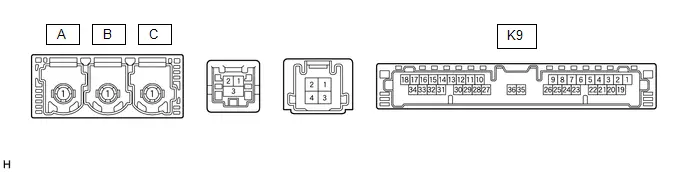
| Terminal No. (Symbol) | Terminal Description | Condition | Specified Condition |
|---|---|---|---|
| K9-1 ( B) - K9-20 (E) | Power source ( B) | Always | 11 to 14 V |
| K9-3 (SIG-) - K9-20 (E) | Ground | Always | Below 1 V |
| K9-4 (IND1) - K9-20 (E) | Manual (SOS) switch red indicator illumination signal | For 2 seconds after turning the ignition switch ON | 1 to 8.5 V |
| Ignition switch off | Below 1 V | ||
| K9-5 (MCVD) - K9-20 (E) | Telephone microphone assembly power supply | Ignition switch ON | 7.5 to 8.5 V |
| Ignition switch off | Below 1 V | ||
| K9-6 (MCI ) - K9-20 (E) | Receive microphone voice signal | Voice being input to telephone microphone assembly | A waveform synchronized with microphone voice signal is input |
| K9-7 (MCI-) - K9-20 (E) | Receive microphone voice signal | Always | Below 1 V |
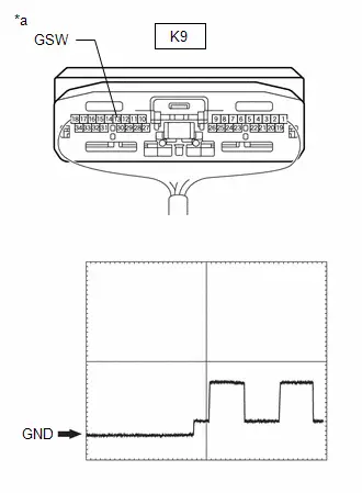
| K9-13 (GSW) - K9-20 (E) | Collision detection signal | Ignition switch ON | Pulse generation (Refer to waveform 1) |
| K9-19 (IG2) - K9-20 (E) | Power source (IG) | Ignition switch ON | 11 to 14 V |
| Ignition switch off | Below 1 V | ||
| K9-20 (E) - Body ground | Ground | Always | Below 1 Ω |
| K9-21 (SIG1) - K9-3 (SIG-) | Manual (SOS) switch button condition signal | Manual (SOS) switch not pressed | 1.3 to 1.9 V |
| Manual (SOS) switch pressed | 0.5 to 0.8 V | ||
| K9-22 (IND2) - K9-20 (E) | Manual (SOS) switch green indicator illumination signal | For 2 seconds after turning the ignition switch ON | 1 to 8.5 V |
| Ignition switch off | Below 1 V | ||
| K9-23 (SGND) - K9-20 (E) | Shield ground | Always | Below 1 Ω |
| K9-25 (CANP) | CAN communication signal | - | - |
| K9-26 (CANN) | CAN communication signal | - | - |
(a) Oscilloscope waveform:
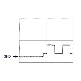
(1) Waveform 1
| Item | Condition |
|---|---|
| Tester connection | K9-13 (GSW) - K9-20 (E) |
| Tool setting | 5.0 V/DIV., 20 ms/DIV. |
| Toyota Prius Vehicle condition | Ignition switch ON |
Diagnosis System
DIAGNOSIS SYSTEM
DESCRIPTION
(a) The DCM (telematics transceiver) control the vehicle safety connect system functions. Safety connect system data and Diagnostic Trouble Codes (DTCs) can be read through the vehicle Data Link Connector 3 (DLC3). In some cases, a malfunction may be occurring in the safety connect system. When the system seems to be malfunctioning, use the GTS to check for malfunctions and perform repairs.
CHECK DLC3
(a) Check the DLC3.
Click here

INSPECT AUXILIARY BATTERY
(a) Measure the auxiliary battery voltage with the ignition switch off.
Standard voltage:
11 to 14 V
HINT:
If the voltage is below 11 V, recharge or replace the auxiliary battery.
CHECK INDICATOR
(a) When a malfunction is detected in the safety connect system, the manual (SOS) switch red indicator on the manual (SOS) switch illuminates to inform the driver of the malfunction.
Click here

Data List / Active Test
DATA LIST / ACTIVE TEST
DATA LIST
NOTICE:
In the table below, the values listed under "Normal Condition" are reference values. Do not depend solely on these reference values when deciding whether a part is faulty or not.
HINT:
Using the GTS to read the Data List allows the values or states of switches, sensors, actuators and other items to be read without removing any parts. This non-intrusive inspection can be very useful because intermittent conditions or signals may be discovered before parts or wiring is disturbed. Reading the Data List information early in troubleshooting is one way to save diagnostic time.
(a) According to the display on the GTS, read the "Data List".
Body Electrical > Telematics > Data List| Tester Display | Measurement Item | Range | Normal Condition | Diagnostic Note |
|---|---|---|---|---|
| Total Distance Traveled | Total distance traveled | Min.: 0, Max.: 16777215 | - | - |
| Total Distance Traveled - Unit | Total distance traveled unit | -, km or mile | - | - |
| IMEI | IMEI of DCM (telematics transceiver) | 15 digits | - | - |
| Software Version High | Software version of DCM (telematics transceiver) (10 digits from left) | 10 digits | - | - |
| Software Version Low | Software version of DCM (telematics transceiver) (10 digits from right) | 10 digits | - | - |
| MSISDN | MSISDN of DCM (telematics transceiver) | 16 digits | - | - |
| PLMN(MCC) | MCC of DCM (telematics transceiver) | 3 digits | - | - |
| PLMN(MNC) | MNC of DCM (telematics transceiver) | 3 digits | - | - |
| ICCID(High) | ICCID of DCM (telematics transceiver) (10 digits from left) | 10 digits | - | - |
| ICCID(Low) | ICCID of DCM (telematics transceiver) (10 digits from right) | 10 digits | - | - |
| Communication Status with TSC | Communication status with Service Center | Incomplete or Complete | Complete | - |
| Telematics Activation Status | DCM (telematics transceiver) activation status | Shipping or Active | Shipping: Not activated Active: Activated | - |
| Remote Toyota Prius Vehicle Tracking | Display "Remote Vehicle Tracking" function enabled/disabled status | Disable or Enable | Disable: Following function disabled Enable: Following function enabled | - |
| Brand TOYOTA | Bland name | No or Yes | No: Except TOYOTA Brand YES: TOYOTA Brand | - |
| OTA Reprogramming | Display "OTA Reprogramming" function enabled/disabled status | Disable or Enable | Disable: Following function disabled Enable: Following function enabled | - |
| HELPNET Function | Display "Helpnet" function enabled/disabled status | Disable or Enable | Disable: Following function disabled Enable: Following function enabled | - |
| Stolen Toyota Prius Vehicle Tracking | Display "Stolen Vehicle Tracking" function enabled/disabled status | Disable or Enable | Disable: Following function disabled Enable: Following function enabled | - |
| Automatic Collision Notification Function | Display "Automatics Collision Notification" function enabled/disabled status | Disable or Enable | Disable: Following function disabled Enable: Following function enabled | - |
| Manual Emergency Call Function | Display "Manual Emergency Call" function enabled/disabled status | Disable or Enable | Disable: Following function disabled Enable: Following function enabled | - |
| Wireless Health Check Function | Display "Wireless Health Check" function enabled/disabled status | Disable or Enable | Disable: Following function disabled Enable: Following function enabled | - |
| Stolen Toyota Prius Vehicle Tracking Function | Display "Stolen Vehicle Tracking" function enabled/disabled status | Disable or Enable | Disable: Following function disabled Enable: Following function enabled | - |
| Telematics Microphone Volume Adjust | Setting of Telematics Microphone Volume Adjust | Min.: 1, Max.:11 | Displays customize setting of Telematics Microphone Volume Adjust | - |
| Telematics Speaker Volume Adjust | Setting of Telematics Speaker Volume Adjust | Min.: 1, Max.:14 | Displays customize setting of Telematics Speaker Volume Adjust | - |
| Green Indicator | The green indicator light on the emergency call switch panel illumination status | Lighting OFF, Nighttime Brightness-Low, Nighttime Brightness-Middle, Nighttime Brightness-High or Daytime Brightness | - | - |
| Red Indicator | The red indicator light on the emergency call switch panel illumination status | Lighting OFF, Nighttime Brightness-Low, Nighttime Brightness-Middle, Nighttime Brightness-High or Daytime Brightness | - | - |
| Beep | Beep volume | Min.: Vol01, Max.:Vol14, OFF | - | - |
ACTIVE TEST
HINT:
Using the GTS to perform Active Tests allows relays, VSVs, actuators and other items to be operated without removing any parts. This non-intrusive functional inspection can be very useful because intermittent operation may be discovered before parts or wiring is disturbed. Performing Active Tests early in troubleshooting is one way to save diagnostic time. Data List information can be displayed while performing Active Tests.
(a) According to the display on the GTS, perform the Active Test.
Body Electrical > Telematics > Active Test| Tester Display | Measurement Item | Control Range | Diagnostic Note |
|---|---|---|---|
| Green Indicator | Operate Emergency Call Switch Green Indicator | Lighting OFF, Nighttime Brightness - Low, Nighttime Brightness - Middle, Nighttime Brightness - High or Daytime Brightness | Operate with ignition switch ON and the Toyota Prius vehicle stopped. |
| Red Indicator | Operate Emergency Call Switch Red Indicator | Lighting OFF, Nighttime Brightness - Low, Nighttime Brightness - Middle, Nighttime Brightness - High or Daytime Brightness | Operate with ignition switch ON and the Toyota Prius vehicle stopped. |
| Beep | Operate speakers | Min.: Vol01, Max.: Vol14 | Operate with ignition switch ON and the vehicle stopped. |
Diagnostic Trouble Code Chart
DIAGNOSTIC TROUBLE CODE CHART
Safety Connect System| DTC No. | Detection Item | DTC Output from | Priority | Link |
|---|---|---|---|---|
| B153711 | Telephone Sub Antenna Circuit Short to Ground | Telematics | A |
|
| B153713 | Telephone Sub Antenna Circuit Open | Telematics | A |
|
| B157011 | Indicator (Red) Circuit Short to Ground | Telematics | A |
|
| B157013 | Indicator (Red) Circuit Open | Telematics | A |
|
| B157111 | Indicator (Green) Circuit Short to Ground | Telematics | A |
|
| B157113 | Indicator (Green) Circuit Open | Telematics | A |
|
| B157213 | Microphone Circuit Open | Telematics | A |
|
| B15A804 | DCM System Internal Failure | Telematics | A |
|
| B15C111 | GNSS Antenna Circuit Short to Ground | Telematics | A |
|
| B15C113 | GNSS Antenna Circuit Open | Telematics | A |
|
| B15C464 | Airbag Signal Signal Plausibility Failure | Telematics | B |
|
| B15C511 | Emergency Call Switch Circuit Short to Ground | Telematics | A |
|
| B15C513 | Emergency Call Switch Circuit Open | Telematics | A |
|
| B15CB11 | Telephone Main Antenna Circuit Short to Ground | Telematics | A |
|
| B15CB13 | Telephone Main Antenna Circuit Open | Telematics | A |
|
| B15CC49 | Backup Battery Internal Electronic Failure | Telematics | A |
|


Vehicle Control History
VEHICLE CONTROL HISTORY
NOTICE:
Make sure to record any output Vehicle Control History codes before clearing them and checking the Vehicle Control History again.
CHECK VEHICLE CONTROL HISTORY
NOTICE:
Depending on the parts that are replaced during Toyota Prius vehicle inspection or maintenance, performing initialization, registration or calibration may be needed. Refer to Precaution for Safety Connect System.
Click here

(a) In accordance with the display of the GTS, check the vehicle control history (RoB).
Body Electrical > Telematics > Utility| Tester Display |
|---|
| Toyota Prius Vehicle Control History (RoB) |
| Code | Tester Display | Description | Diagnostic Note |
|---|---|---|---|
| X2210 | Life Cycle of DCM Backup Battery | When the system detects that the mobilephone battery has reached the end of its lifespan. |
NOTICE:
|
| X2211 | Low DCM Backup Battery Charge | When the mobilephone battery charge is low. | - |
| X2601 | Software Inconsistency with ENG/HV Control Module | The VIN number received via CAN communication does not match that stored in the DCM. |
|
| X2213 | Emergency Call Switch Stuck On | The manual (SOS) switch is on for 5 minutes or more. |
|
| X2214 | Communication Blackout from Power Distribution Controller ECU | Lost Communication with ECM. | Check CAN Communication System
|
| X2212 | Diagnostics Communication Flow Failure | Diagnostics communication flow failure (ID, Mode/SID difference). | - |
| X2215 | Non Approval of the Reprograming | User did not approve software update. | - |
| X2216 | Failure of the Reprogramming | Software writing failed. | - |
| X2217 | Inconsistent Startup Software | Software writing succeeded, but started software does not match package. | - |
| X21D4 | Reprograming Telematics ECU by OTA Start/Finish | The software update of DCM by OTA is started and completed with success. | - |


CLEAR Toyota Prius Vehicle CONTROL HISTORY
NOTICE:
By performing this procedure, all stored Vehicle Control History will be cleared.
(a) Using the GTS, select the vehicle control history (Rob).
Body Electrical > Telematics > Utility| Tester Display |
|---|
| Toyota Prius Vehicle Control History (RoB) |
(b) According to the display on the GTS, clear the Vehicle Control History (RoB).
Indicator (Red) Circuit Short to Ground (B157011,B157013)
DESCRIPTION
This DTC is stored when the DCM (telematics transceiver) detects an open or short in the manual (SOS) switch red indicator circuit of the manual (SOS) switch.
The manual (SOS) switch red indicator illuminates for 2 seconds and goes off when the ignition switch is turned to ON. If a malfunction in the safety connect system is detected, the manual (SOS) switch red indicator will illuminate.
However, the manual (SOS) switch red indicator may not illuminate when this DTC is stored.
| DTC No. | Detection Item | DTC Detection Condition | Trouble Area | DTC Output from | Priority |
|---|---|---|---|---|---|
| B157011 | Indicator (Red) Circuit Short to Ground | Manual (SOS) switch red indicator impedance (Ω) is lower than the malfunction threshold for 10 seconds or more when the ignition switch is ON |
| Telematics | A |
| B157013 | Indicator (Red) Circuit Open | Manual (SOS) switch red indicator impedance (Ω) is higher than the malfunction threshold for 10 seconds or more when the ignition switch is ON |
| Telematics | A |
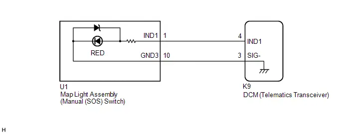
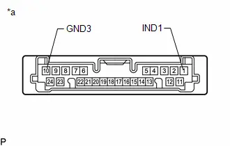
WIRING DIAGRAM
CAUTION / NOTICE / HINT
NOTICE:
Depending on the parts that are replaced during Toyota Prius vehicle inspection or maintenance, performing initialization, registration or calibration may be needed. Refer to Precaution for Safety Connect System.
Click here

HINT:
If DTC B157011 or B157013 is stored, the manual (SOS) switch red indicator may not illuminate when another DTC is stored.
PROCEDURE
| 1. | CLEAR DTC |
(a) Turn the ignition switch to ON and wait for 10 seconds or more.
(b) Clear the DTCs.
Body Electrical > Telematics > Clear DTCs
|

| 2. | CHECK DTC |
Pre-procedure1
(a) Turn the ignition switch to ON and wait for 10 seconds or more.
Procedure1
(b) Check for DTCs and check that no DTCs are output.
Body Electrical > Telematics > Trouble CodesOK:
No DTCs are output.
| Result | Proceed to |
|---|---|
| B157011 or B157013 is not output | A |
| B157011 or B157013 is output | B |
Post-procedure1
(c) None
| A |

| USE SIMULATION METHOD TO CHECK |
|

| 3. | INSPECT MAP LIGHT ASSEMBLY (MANUAL (SOS) SWITCH) (RED INDICATOR) |
Pre-procedure1
(a) Remove the map light assembly (manual (SOS) switch).
HINT:
Click here

(b) Connect 2 dry-cell batteries (1.5 V each) in series.
| (c) Connect a positive ( ) lead from the batteries to terminal 1 (IND1) and a negative (-) lead to terminal 10 (GND3) of the map light assembly (manual (SOS) switch) connector. |
|
Procedure1
(d) Check if the manual (SOS) switch red indicator illuminates.
OK:
Manual (SOS) switch red indicator illuminates.
Post-procedure1
(e) None
| NG |

| REPLACE MAP LIGHT ASSEMBLY (MANUAL (SOS) SWITCH) |
|

| 4. | CHECK HARNESS AND CONNECTOR (DCM (TELEMATICS TRANSCEIVER) - MAP LIGHT ASSEMBLY (MANUAL (SOS) SWITCH)) |
Pre-procedure1
(a) Disconnect the K9 DCM (telematics transceiver) connector.
(b) Disconnect the U1 map light assembly (manual (SOS) switch) connector.
Procedure1
(c) Measure the resistance according to the value(s) in the table below.
Standard Resistance:
 Click Location & Routing(K9,U1) Click Connector(K9) Click Connector(U1)
 | Tester Connection | Condition | Specified Condition | Result |
|---|---|---|---|
| K9-4 (IND1) - U1-1 (IND1) | Always | Below 1 Ω | Ω |
| K9-4 (IND1) or U1-1 (IND1) - Body ground | Always | 10 kΩ or higher | kΩ |
| K9-3 (SIG-) - U1-10 (GND3) | Always | Below 1 Ω | Ω |
| K9-3 (SIG-) or U1-10 (GND3) - Body ground | Always | 10 kΩ or higher | kΩ |
Post-procedure1
(d) None
| NG |

| REPAIR OR REPLACE HARNESS OR CONNECTOR |
|

| 5. | REPLACE DCM (TELEMATICS TRANSCEIVER) |
(a) Replace the DCM (telematics transceiver) with a new one.
HINT:
Click here

NOTICE:
- The ignition switch must be off.
- Do not exchange the DCM (telematics transceiver) with one from another Toyota Prius vehicle.
| NEXT |

| PERFORM DCM ACTIVATION |
Microphone Circuit Open (B157213)
DESCRIPTION
This DTC is stored when the DCM (telematics transceiver) detects a malfunction in the telephone microphone assembly circuit.
| DTC No. | Detection Item | DTC Detection Condition | Trouble Area | DTC Output from | Priority |
|---|---|---|---|---|---|
| B157213 | Microphone Circuit Open | Current at terminal MCVD is lower than the malfunction threshold for 10 seconds or more while the ignition switch is ON |
| Telematics | A |
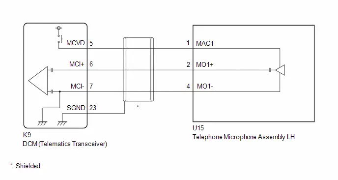
WIRING DIAGRAM
CAUTION / NOTICE / HINT
NOTICE:
Depending on the parts that are replaced during Toyota Prius vehicle inspection or maintenance, performing initialization, registration or calibration may be needed. Refer to Precaution for Safety Connect System.
Click here

PROCEDURE
| 1. | CLEAR DTC |
(a) Turn the ignition switch to ON and wait for 10 seconds or more.
(b) Clear the DTCs.
Body Electrical > Telematics > Clear DTCs
|

| 2. | CHECK DTC |
Pre-procedure1
(a) Turn the ignition switch to ON and wait for 10 seconds or more.
Procedure1
(b) Check for DTCs and check that no DTCs are output.
Body Electrical > Telematics > Trouble CodesOK:
No DTCs are output.
| Result | Proceed to |
|---|---|
| B157213 is not output | A |
| B157213 is output | B |
Post-procedure1
(c) None
| A |

| USE SIMULATION METHOD TO CHECK |
|

| 3. | CHECK HARNESS AND CONNECTOR (DCM (TELEMATICS TRANSCEIVER) - TELEPHONE MICROPHONE ASSEMBLY LH) |
Pre-procedure1
(a) Disconnect the K9 DCM (telematics transceiver) connector.
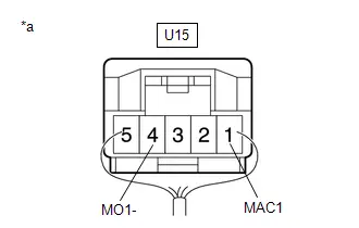
(b) Disconnect the U15 telephone microphone assembly LH connector.
Procedure1
(c) Measure the resistance according to the value(s) in the table below.
Standard Resistance:
 Click Location & Routing(K9,U15) Click Connector(K9) Click Connector(U15)
 | Tester Connection | Condition | Specified Condition | Result |
|---|---|---|---|
| K9-5 (MCVD) - U15-1 (MAC1) | Always | Below 1 Ω | Ω |
| K9-6 (MCI ) - U15-2 (MO1 ) | Always | Below 1 Ω | Ω |
| K9-7 (MCI-) - U15-4 (MO1-) | Always | Below 1 Ω | Ω |
| K9-23 (SGND) - Body ground | Always | 10 kΩ or higher | kΩ |
| K9-5 (MCVD) or U15-1 (MAC1) - Body ground | Always | 10 kΩ or higher | kΩ |
| K9-6 (MCI ) or U15-2 (MO1 ) - Body ground | Always | 10 kΩ or higher | kΩ |
| K9-7 (MCI-) or U15-4 (MO1-) - Body ground | Always | 10 kΩ or higher | kΩ |
Post-procedure1
(d) None
| NG |

| REPAIR OR REPLACE HARNESS OR CONNECTOR |
|

| 4. | CHECK DCM (TELEMATICS TRANSCEIVER) (TELEPHONE MICROPHONE ASSEMBLY LH POWER SOURCE) |
Pre-procedure1
(a) Remove the telephone microphone assembly LH but do not disconnect the connectors.
HINT:
Click here


Procedure1
| (b) Measure the voltage and resistance according to the value(s) in the table below. Standard Voltage:  Click Location & Routing(U15) Click Connector(U15) Click Location & Routing(U15) Click Connector(U15)
Standard Resistance:  Click Location & Routing(U15) Click Connector(U15) Click Location & Routing(U15) Click Connector(U15)
Result:
|
|
Post-procedure1
(c) None
| OK |

| REPLACE TELEPHONE MICROPHONE ASSEMBLY LH
|


|

| 5. | REPLACE DCM (TELEMATICS TRANSCEIVER) |
(a) Replace the DCM (telematics transceiver) with a new one.
HINT:
Click here

NOTICE:
- The ignition switch must be off.
- Do not exchange the DCM (telematics transceiver) with one from another Toyota Prius vehicle.
| NEXT |

| PERFORM DCM ACTIVATION |
DCM System Internal Failure (B15A804)
DESCRIPTION
This DTC is stored when an internal circuit malfunction is detected by the DCM (telematics transceiver) self check.
| DTC No. | Detection Item | DTC Detection Condition | Trouble Area | DTC Output from | Priority |
|---|---|---|---|---|---|
| B15A804 | DCM System Internal Failure | DCM (telematics transceiver) internal malfunction | DCM (telematics transceiver) | Telematics | A |
CAUTION / NOTICE / HINT
NOTICE:
- Regardless of whether DTC B15A804 has been output as a present or history DTC, the DCM (telematics transceiver) should be replaced.
-
Depending on the parts that are replaced during Toyota Prius vehicle inspection or maintenance, performing initialization, registration or calibration may be needed. Refer to Precaution for Safety Connect System.
Click here

PROCEDURE
| 1. | REPLACE DCM (TELEMATICS TRANSCEIVER) |
(a) Replace the DCM (telematics transceiver) with a new one.
HINT:
Click here

NOTICE:
- The ignition switch must be off.
- Do not exchange the DCM (telematics transceiver) with one from another Toyota Prius vehicle.
| NEXT |

| PERFORM DCM ACTIVATION |
GNSS Antenna Circuit Short to Ground (B15C111,B15C113)
DESCRIPTION
These DTCs are stored when a malfunction occurs in the telephone and GPS antenna assembly (for Front Side) circuit.
| DTC No. | Detection Item | DTC Detection Condition | Trouble Area | DTC Output from | Priority |
|---|---|---|---|---|---|
| B15C111 | GNSS Antenna Circuit Short to Ground | Current to the GNSS antenna is lower than the malfunction threshold for 10 seconds or more when the ignition switch is ON (Short circuit) |
| Telematics | A |
| B15C113 | GNSS Antenna Circuit Open | Current to the GNSS antenna is higher than the malfunction threshold for 10 seconds or more when the ignition switch is ON (Open circuit) |
| Telematics | A |
WIRING DIAGRAM
CAUTION / NOTICE / HINT
NOTICE:
Depending on the parts that are replaced during Toyota Prius vehicle inspection or maintenance, performing initialization, registration or calibration may be needed. Refer to Precaution for Safety Connect System.
Click here

HINT:
Refer to "PARTS LOCATION" for the installation location of telephone and GPS antenna cord.
Click here

PROCEDURE
| 1. | CLEAR DTC |
(a) Turn the ignition switch to ON and wait for 10 seconds or more.
(b) Clear the DTCs.
Body Electrical > Telematics > Clear DTCs
|

| 2. | CHECK DTC |
Pre-procedure1
(a) Turn the ignition switch to ON and wait for 10 seconds or more.
Procedure1
(b) Check for DTCs and check that no DTCs are output.
Body Electrical > Telematics > Trouble CodesOK:
No DTCs are output.
| Result | Proceed to |
|---|---|
| B15C111 or B15C113 is not output | A |
| B15C111 or B15C113 is output | B |
Post-procedure1
(c) None
| A |

| USE SIMULATION METHOD TO CHECK |
|

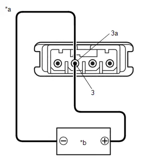
| 3. | INSPECT TELEPHONE AND GPS ANTENNA (for Front Side) |
Pre-procedure1
(a) Remove the telephone and GPS antenna (for Front Side).
HINT:
Click here


Procedure1
(b) Current consumption check:
| (1) Measure the current consumption according to the value(s) in the table below. Standard Current:
NOTICE: Do not apply 6 V or more between terminals 3 and 3a. HINT: If a stable power supply is not available, connect 4 nickel-metal hydride batteries (1.2 V each) or equivalent in series. Result:
|
|
Post-procedure1
(c) None
| NG |

| REPLACE TELEPHONE AND GPS ANTENNA (for Front Side)
|


|

| 4. | INSPECT TELEPHONE AND GPS ANTENNA CORD (ANTENNA CORD SUB-ASSEMBLY (for Type A)) |
Pre-procedure1
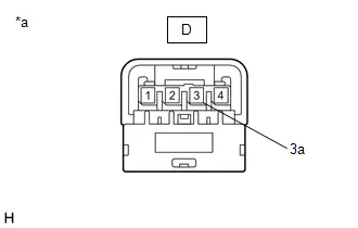
| (a) Disconnect the D telephone and GPS antenna cord (antenna cord sub-assembly (for Type A)) connector. |
|
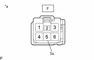
| (b) Disconnect the F telephone and GPS antenna cord (antenna cord sub-assembly (for Type A)) connector. |
|
Procedure1
(c) Measure the resistance according to the value(s) in the table below.
Standard Resistance:
| Tester Connection | Condition | Specified Condition | Result |
|---|---|---|---|
| D-3 - F-5 | Always | Below 1 Ω | Ω |
| D-3 or F-5 - Body ground | Always | 10 kΩ or higher | kΩ |
| D-3a - F-5a | Always | Below 1 Ω | Ω |
| D-3a or F-5a - Body ground | Always | 10 kΩ or higher | kΩ |
Post-procedure1
(d) None
| NG |

| REPLACE TELEPHONE AND GPS ANTENNA CORD (ANTENNA CORD SUB-ASSEMBLY (for Type A))
|


|

| 5. | INSPECT TELEPHONE AND GPS ANTENNA CORD (ANTENNA CORD SUB-ASSEMBLY (for Type B)) |
Pre-procedure1
| (a) Disconnect the E telephone and GPS antenna cord (antenna cord sub-assembly (for Type B)) connector. |
|
| (b) Disconnect the B telephone and GPS antenna cord (antenna cord sub-assembly (for Type B)) connector. |
|
Procedure1
(c) Measure the resistance according to the value(s) in the table below.
Standard Resistance:
| Tester Connection | Condition | Specified Condition | Result |
|---|---|---|---|
| E-5 - B-1 | Always | Below 1 Ω | Ω |
| E-5 or B-1 - Body ground | Always | 10 kΩ or higher | kΩ |
| E-5a - B-1a | Always | Below 1 Ω | Ω |
| E-5a or B-1a - Body ground | Always | 10 kΩ or higher | kΩ |
Post-procedure1
(d) None
| NG |

| REPLACE TELEPHONE AND GPS ANTENNA CORD (ANTENNA CORD SUB-ASSEMBLY (for Type B)) |
|

| 6. | REPLACE DCM (TELEMATICS TRANSCEIVER) |
(a) Replace the DCM (telematics transceiver) with a new one.
HINT:
Click here

NOTICE:
- The ignition switch must be off.
- Do not exchange the DCM (telematics transceiver) with one from another Toyota Prius vehicle.
| NEXT |

| PERFORM DCM ACTIVATION |
Airbag Signal Signal Plausibility Failure (B15C464)
DESCRIPTION
If the DCM (telematics transceiver) detects an error in communication between the DCM (telematics transceiver) and the airbag sensor assembly as a result of the DCM (telematics transceiver) self check, this DTC will be stored.
| DTC No. | Detection Item | DTC Detection Condition | Trouble Area | DTC Output from | Priority |
|---|---|---|---|---|---|
| B15C464 | Airbag Signal Signal Plausibility Failure | DCM (telematics transceiver) detects an error in signals from airbag sensor assembly when ignition switch is ON. |
| Telematics | B |
WIRING DIAGRAM
CAUTION / NOTICE / HINT
NOTICE:
-
The Toyota Prius vehicle is equipped with an SRS (Supplemental Restraint System) which includes components such as airbags. Before servicing (including removal or installation of parts), be sure to read the Precaution in the SRS.
Click here

-
After the ignition switch is turned off, there may be a waiting time before disconnecting the negative (-) auxiliary battery terminal.
Click here

HINT:
When disconnecting and reconnecting the auxiliary battery, there is an automatic learning function that completes learning when the respective system is used.
Click here


PROCEDURE
| 1. | CHECK DTC (AIRBAG SYSTEM) |
Pre-procedure1
(a) Turn the ignition switch to ON, and wait for at least 60 seconds.
(b) Clear the DTCs.
Body Electrical > SRS Airbag > Clear DTCsProcedure1
(c) Check for DTCs and check that no DTCs are output.
Body Electrical > SRS Airbag > Trouble CodesOK:
No DTCs are output.
| Result | Proceed to |
|---|---|
| DTCs are not output | A |
| DTCs are output | B |
Post-procedure1
(d) None
| B |

| GO TO AIRBAG SYSTEM
|


|

| 2. | CLEAR DTC |
(a) Turn the ignition switch to ON and wait for 10 seconds or more.
(b) Clear the DTCs.
Body Electrical > Telematics > Clear DTCs
|

| 3. | CHECK DTC |
Pre-procedure1
(a) Turn the ignition switch to ON and wait for 10 seconds or more.
Procedure1
(b) Check for DTCs and check that no DTCs are output.
Body Electrical > Telematics > Trouble CodesOK:
No DTCs are output.
| Result | Proceed to |
|---|---|
| B15C464 is not output | A |
| B15C464 is output | B |
Post-procedure1
(c) None
| A |

| USE SIMULATION METHOD TO CHECK |
|

| 4. | CHECK DCM (TELEMATICS TRANSCEIVER) (GSW SIGNAL) |
Pre-procedure1
(a) Remove the DCM (telematics transceiver) but do not disconnect the connectors.
HINT:
Click here

Procedure1
| (b) Check the input waveform. (1) Check the signal waveform according to the condition(s) in the table below. (Check the waveform from the back of the wire harness connector of the DCM (telematics transceiver) while the airbag sensor assembly connectors are connected.) Reference Waveform:
OK: The waveform is similar to that shown in the illustration. Result:
|
|
Post-procedure1
(c) None
| NG |

| GO TO STEP 6 |
|

| 5. | REPLACE DCM (TELEMATICS TRANSCEIVER) |
(a) Replace the DCM (telematics transceiver) with a new one.
HINT:
Click here

NOTICE:
- The ignition switch must be off.
- Do not exchange the DCM (telematics transceiver) with one from another Toyota Prius vehicle.
| NEXT |

| PERFORM DCM ACTIVATION |
| 6. | CHECK HARNESS AND CONNECTOR (DCM (TELEMATICS TRANSCEIVER) - AIRBAG ECU ASSEMBLY) |
Pre-procedure1
(a) Disconnect the K9 DCM (telematics transceiver) connector.
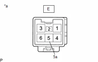
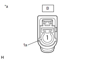
(b) Disconnect the K1 airbag ECU assembly connector.
Procedure1
(c) Measure the resistance according to the value(s) in the table below.
Standard Resistance:
 Click Location & Routing(K9,K1) Click Connector(K9) Click Connector(K1)
 | Tester Connection | Condition | Specified Condition | Result |
|---|---|---|---|
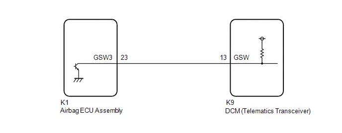
| K9-13 (GSW) - K1-23 (GSW3) | Always | Below 1 Ω | Ω |
| K9-13 (GSW) or K1-23 (GSW3) - Body ground | Always | 10 kΩ or higher | kΩ |
Post-procedure1
(d) None
| OK |

| REPLACE AIRBAG ECU ASSEMBLY
|


| NG |

| REPAIR OR REPLACE HARNESS OR CONNECTOR |
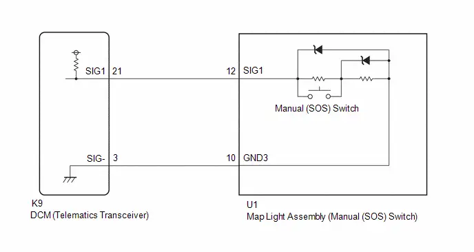
Emergency Call Switch Circuit Short to Ground (B15C511,B15C513)
DESCRIPTION
If the DCM (telematics transceiver) detects an error in the communication between the DCM (telematics transceiver) and the map light assembly (manual (SOS) switch) as a result of the DCM (telematics transceiver) self check, this DTC will be stored.
| DTC No. | Detection Item | DTC Detection Condition | Trouble Area | DTC Output from | Priority |
|---|---|---|---|---|---|
| B15C511 | Emergency Call Switch Circuit Short to Ground | Manual (SOS) switch impedance (Ω) is lower than the malfunction threshold for 10 seconds or more when the ignition switch is ON |
| Telematics | A |
| B15C513 | Emergency Call Switch Circuit Open | Manual (SOS) switch impedance (Ω) is higher than the malfunction threshold for 10 seconds or more when the ignition switch is ON |
| Telematics | A |
WIRING DIAGRAM
CAUTION / NOTICE / HINT
NOTICE:
Depending on the parts that are replaced during Toyota Prius vehicle inspection or maintenance, performing initialization, registration or calibration may be needed. Refer to Precaution for Safety Connect System.
Click here

PROCEDURE
| 1. | CLEAR DTC |
(a) Turn the ignition switch to ON and wait for 10 seconds or more.
(b) Clear the DTCs.
Body Electrical > Telematics > Clear DTCs
|

| 2. | CHECK DTC |
Pre-procedure1
(a) Turn the ignition switch to ON and wait for 10 seconds or more.
Procedure1
(b) Check for DTCs and check that no DTCs are output.
Body Electrical > Telematics > Trouble CodesOK:
No DTCs are output.
| Result | Proceed to |
|---|---|
| B15C511 or B15C513 is not output | A |
| B15C511 or B15C513 is output | B |
Post-procedure1
(c) None
| A |

| USE SIMULATION METHOD TO CHECK |
|

| 3. | INSPECT MAP LIGHT ASSEMBLY (MANUAL (SOS) SWITCH) |
Pre-procedure1
(a) Remove the map light assembly (manual (SOS) switch).
HINT:
Click here

Procedure1
| (b) Measure the resistance according to the value(s) in the table below. Standard Resistance:
Result:
|
|
Post-procedure1
(c) None
| NG |

| REPLACE MAP LIGHT ASSEMBLY (MANUAL (SOS) SWITCH) |
|

| 4. | CHECK HARNESS AND CONNECTOR (DCM (TELEMATICS TRANSCEIVER) - MAP LIGHT ASSEMBLY (MANUAL (SOS) SWITCH)) |
Pre-procedure1
(a) Disconnect the K9 DCM (telematics transceiver) connector.
(b) Disconnect the U1 map light assembly (manual (SOS) switch) connector.
Procedure1
(c) Measure the resistance according to the value(s) in the table below.
Standard Resistance:
 Click Location & Routing(K9,U1) Click Connector(K9) Click Connector(U1)
 | Tester Connection | Condition | Specified Condition | Result |
|---|---|---|---|
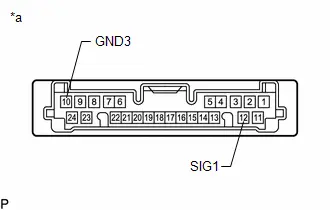
| K9-21 (SIG1) - U1-12 (SIG1) | Always | Below 1 Ω | Ω |
| K9-3 (SIG-) - U1-10 (GND3) | Always | Below 1 Ω | Ω |
| K9-21 (SIG1) or U1-12 (SIG1) - Body ground | Always | 10 kΩ or higher | kΩ |
| K9-3 (SIG-) or U1-10 (GND3) - Body ground | Always | 10 kΩ or higher | kΩ |
Post-procedure1
(d) None
| NG |

| REPAIR OR REPLACE HARNESS OR CONNECTOR |
|

| 5. | REPLACE DCM (TELEMATICS TRANSCEIVER) |
(a) Replace the DCM (telematics transceiver) with a new one.
HINT:
Click here

NOTICE:
- The ignition switch must be off.
- Do not exchange the DCM (telematics transceiver) with one from another Toyota Prius vehicle.
| NEXT |

| PERFORM DCM ACTIVATION |
Telephone Main Antenna Circuit Short to Ground (B15CB11,B15CB13)
DESCRIPTION
This DTC is stored when the DCM (telematics transceiver) detects an open or a short in the telephone antenna (main) circuit.
| DTC No. | Detection Item | DTC Detection Condition | Trouble Area | DTC Output from | Priority |
|---|---|---|---|---|---|
| B15CB11 | Telephone Main Antenna Circuit Short to Ground | Telephone antenna (main) impedance (Ω) is lower than the malfunction threshold for 10 seconds or more when the ignition switch is ON (Short circuit) |
| Telematics | A |
| B15CB13 | Telephone Main Antenna Circuit Open | Telephone antenna (main) impedance (Ω) is higher than the malfunction threshold for 10 seconds or more when the ignition switch is ON (Open circuit) |
| Telematics | A |
WIRING DIAGRAM
CAUTION / NOTICE / HINT
NOTICE:
Depending on the parts that are replaced during Toyota Prius vehicle inspection or maintenance, performing initialization, registration or calibration may be needed. Refer to Precaution for Safety Connect System.
Click here

HINT:
Refer to "PARTS LOCATION" for the installation location of telephone and GPS antenna cord.
Click here

PROCEDURE
| 1. | CLEAR DTC |
(a) Turn the ignition switch to ON and wait for 10 seconds or more.
(b) Clear the DTCs.
Body Electrical > Telematics > Clear DTCs
|

| 2. | CHECK DTC |
Pre-procedure1
(a) Turn the ignition switch to ON and wait for 10 seconds or more.
Procedure1
(b) Check for DTCs and check that no DTCs are output.
Body Electrical > Telematics > Trouble CodesOK:
No DTCs are output.
| Result | Proceed to |
|---|---|
| B15CB11 or B15CB13 is not output | A |
| B15CB11 or B15CB13 is output | B |
Post-procedure1
(c) None
| A |

| USE SIMULATION METHOD TO CHECK |
|

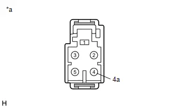
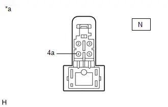
| 3. | INSPECT TELEPHONE AND GPS ANTENNA ASSEMBLY (for Roof Side) |
Pre-procedure1
| (a) Disconnect the telephone and GPS antenna assembly (for Roof Side) connector. |
|
Procedure1
(b) Measure the resistance according to the value(s) in the table below.
Standard Resistance:
| Tester Connection | Condition | Specified Condition | Result |
|---|---|---|---|
| 4 - 4a | Always | 9 to 11 kΩ | kΩ |
Post-procedure1
(c) None
| NG |

| REPLACE TELEPHONE AND GPS ANTENNA ASSEMBLY (for Roof Side)
|


|

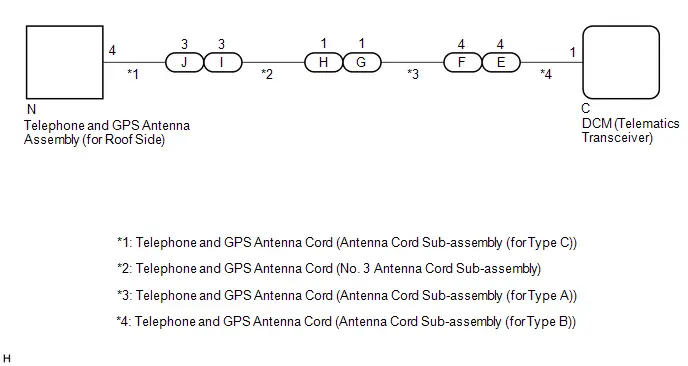
| 4. | INSPECT TELEPHONE AND GPS ANTENNA CORD (ANTENNA CORD SUB-ASSEMBLY (Type C)) |
Pre-procedure1
| (a) Disconnect the N telephone and GPS antenna cord (antenna cord sub-assembly (for Type C)) connector. |
|
| (b) Disconnect the J telephone and GPS antenna cord (antenna cord sub-assembly (for Type C)) connector. |
|
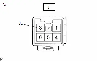
Procedure1
(c) Measure the resistance according to the value(s) in the table below.
Standard Resistance:
| Tester Connection | Condition | Specified Condition | Result |
|---|---|---|---|
| N-4 - J-3 | Always | Below 1 Ω | Ω |
| N-4 or J-3 - Body ground | Always | 10 kΩ or higher | kΩ |
| N-4a - J-3a | Always | Below 1 Ω | Ω |
| N-4a or J-3a - Body ground | Always | 10 kΩ or higher | kΩ |
Post-procedure1
(d) None
| NG |

| REPLACE TELEPHONE AND GPS ANTENNA CORD (ANTENNA CORD SUB-ASSEMBLY (for Type C))
|


|

| 5. | INSPECT TELEPHONE AND GPS ANTENNA CORD (NO. 3 ANTENNA CORD SUB-ASSEMBLY) |
Pre-procedure1
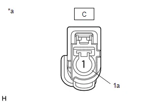
| (a) Disconnect the I telephone and GPS antenna cord (No. 3 antenna cord sub-assembly) connector. |
|
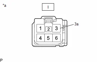
| (b) Disconnect the H telephone and GPS antenna cord (No. 3 antenna cord sub-assembly) connector. |
|
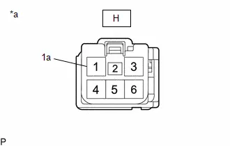
Procedure1
(c) Measure the resistance according to the value(s) in the table below.
Standard Resistance:
| Tester Connection | Condition | Specified Condition | Result |
|---|---|---|---|
| I-3 - H-1 | Always | Below 1 Ω | Ω |
| I-3 or H-1 - Body ground | Always | 10 kΩ or higher | kΩ |
| I-3a - H-1a | Always | Below 1 Ω | Ω |
| I-3a or H-1a - Body ground | Always | 10 kΩ or higher | kΩ |
Post-procedure1
(d) None
| NG |

| REPLACE TELEPHONE AND GPS ANTENNA CORD (NO. 3 ANTENNA CORD SUB-ASSEMBLY)
|


|

| 6. | INSPECT TELEPHONE AND GPS ANTENNA CORD (ANTENNA CORD SUB-ASSEMBLY (for Type A)) |
Pre-procedure1
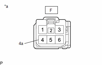
| (a) Disconnect the G telephone and GPS antenna cord (antenna cord sub-assembly (for Type A)) connector. |
|
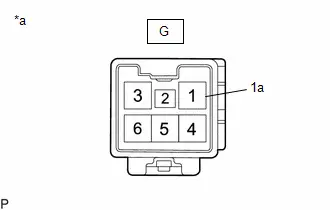
| (b) Disconnect the F telephone and GPS antenna cord (antenna cord sub-assembly for Type A)) connector. |
|
Procedure1
(c) Measure the resistance according to the value(s) in the table below.
Standard Resistance:
| Tester Connection | Condition | Specified Condition | Result |
|---|---|---|---|
| G-1 - F-4 | Always | Below 1 Ω | Ω |
| G-1 or F-4- Body ground | Always | 10 kΩ or higher | kΩ |
| G-1a - F-4a | Always | Below 1 Ω | Ω |
| G-1a or F-4a - Body ground | Always | 10 kΩ or higher | kΩ |
Post-procedure1
(d) None
| NG |

| REPLACE TELEPHONE AND GPS ANTENNA CORD (ANTENNA CORD SUB-ASSEMBLY (for Type A))
|


|

| 7. | INSPECT TELEPHONE AND GPS ANTENNA CORD (ANTENNA CORD SUB-ASSEMBLY (for Type B)) |
Pre-procedure1
| (a) Disconnect the E telephone and GPS antenna cord (antenna cord sub-assembly (for Type B)) connector. |
|
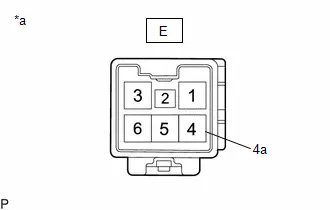
| (b) Disconnect the C telephone and GPS antenna cord (antenna cord sub-assembly (for Type B)) connector. |
|
Procedure1
(c) Measure the resistance according to the value(s) in the table below.
Standard Resistance:
| Tester Connection | Condition | Specified Condition | Result |
|---|---|---|---|
| E-4 - C-1 | Always | Below 1 Ω | Ω |
| E-4 or C-1- Body ground | Always | 10 kΩ or higher | kΩ |
| E-4a - C-1a | Always | Below 1 Ω | Ω |
| E-4a or C-1a - Body ground | Always | 10 kΩ or higher | kΩ |
Post-procedure1
(d) None
| NG |

| REPLACE TELEPHONE AND GPS ANTENNA CORD (ANTENNA CORD SUB-ASSEMBLY (for Type B)) |
|

| 8. | REPLACE DCM (TELEMATICS TRANSCEIVER) |
(a) Replace the DCM (telematics transceiver) with a new one.
HINT:
Click here

NOTICE:
- The ignition switch must be off.
- Do not swap the DCM (telematics transceiver) with one from another Toyota Prius vehicle.
| NEXT |

| PERFORM DCM ACTIVATION |
Backup Battery Internal Electronic Failure (B15CC49)
DESCRIPTION
This DTC is set when the DCM (telematics transceiver) detects one of the following:
- The mobilephone battery voltage drops or the mobilephone battery malfunctions.
- The mobilephone battery temperature is (temporarily) high.
| DTC No. | Detection Item | DTC Detection Condition | Trouble Area | DTC Output from | Priority |
|---|---|---|---|---|---|
| B15CC49 | Backup Battery Internal Electronic Failure | Mobilephone battery malfunction |
| Telematics | A |
CAUTION / NOTICE / HINT
NOTICE:
Depending on the parts that are replaced during Toyota Prius vehicle inspection or maintenance, performing initialization, registration or calibration may be needed. Refer to Precaution for Safety Connect System.
Click here

PROCEDURE
| 1. | CLEAR DTC |
(a) Turn the ignition switch to ON and wait for 10 seconds or more.
(b) Clear the DTCs.
Body Electrical > Telematics > Clear DTCs
|

| 2. | CHECK DTC |
Pre-procedure1
(a) Turn the ignition switch to ON and wait for 10 seconds or more.
Procedure1
(b) Check for DTCs and check that no DTCs are output.
Body Electrical > Telematics > Trouble Codes| Result | Proceed to |
|---|---|
| B15CC49 is not output | A |
| B15CC49 is output | B |
Post-procedure1
(c) None
| A |

| USE SIMULATION METHOD TO CHECK |
|

| 3. | CHECK MOBILEPHONE BATTERY |
(a) Replace the mobilephone battery with a normal one and check if the same problem occurs again.
HINT:
Click here

NOTICE:
-
The mobilephone battery must not be replaced while an ACN call is in progress.
Click here

-
After replacing the mobilephone battery, perform initialization.
Click here

|

| 4. | CLEAR DTC |
(a) Turn the ignition switch to ON and wait for 10 seconds or more.
(b) Clear the DTCs.
Body Electrical > Telematics > Clear DTCs
|

| 5. | CHECK FOR DTC |
(a) Recheck for DTCs and check that no DTCs are output.
Body Electrical > Telematics > Trouble Codes| Result | Proceed to |
|---|---|
| B15CC49 is not output | A |
| B15CC49 is output | B |
| A |

| PERFORM INITIALIZATION |
|

| 6. | REPLACE DCM (TELEMATICS TRANSCEIVER) |
(a) Replace the DCM (telematics transceiver) with a new one.
HINT:
Click here

NOTICE:
- The ignition switch must be off.
- Do not exchange the DCM (telematics transceiver) with one from another Toyota Prius vehicle.
| NEXT |

| PERFORM DCM ACTIVATION |
Green Indicator Remains Off
DESCRIPTION
After the ignition switch is turned to ON, the DCM (telematics transceiver) will enter into self check mode. The manual (SOS) switch red indicator will illuminate for 2 seconds and turn off followed by the manual (SOS) switch green indicator illuminating and remaining on under normal operation. If neither the red nor green indicators remain on, verification of the subscription should be performed.
PROCEDURE
| 1. | CONFIRM GREEN INDICATOR COMES ON |
(a) After the ignition switch is turned to ON and the manual (SOS) switch red indicator has come on for 2 seconds, confirm that the manual (SOS) switch green indicator comes on for 2 seconds.
OK:
Green indicator comes on.
| NG |

| GO TO STEP 6 |
|

| 2. | CONFIRM SUBSCRIPTION MODE |
(a) Confirm the indicator status 5 seconds after the ignition switch is turned to ON.
| Result | Proceed to |
|---|---|
| Green indicator remains on | A |
| Green indicator remains off | B |
| A |

| USE SIMULATION METHOD TO CHECK |
|

| 3. | INPUT VIN WITH GTS |
(a) Turn the ignition switch to ON and wait for 10 seconds.
(b) Click "VIN Synchronization" on the Utility Selection Menu.
Click here

|

| 4. | CONFIRM SUBSCRIPTION MODE |
(a) Confirm the indicator status at 5 seconds after the ignition switch is turned to ON.
| Result | Proceed to |
|---|---|
| Green indicator remains on | A |
| Green indicator remains off | B |
| A |

| END |
|

| 5. | REPLACE DCM (TELEMATICS TRANSCEIVER) |
(a) Replace the DCM (telematics transceiver) with a new one.
Click here

NOTICE:
- The ignition switch must be off.
- Do not exchange the DCM (telematics transceiver) with one from another Toyota Prius vehicle.
| NEXT |

| PERFORM DCM ACTIVATION |
| 6. | CHECK DTC |
(a) Turn the ignition switch to ON and wait for 10 seconds or more.
(b) Clear the DTCs.
Body Electrical > Telematics > Clear DTCs(c) Check for DTCs and check that no DTCs are output.
Body Electrical > Telematics > Trouble CodesOK:
No DTCs are output.
| NG |

| GO TO DIAGNOSTIC TROUBLE CODE CHART |
|

| 7. | REPLACE DCM (TELEMATICS TRANSCEIVER) |
(a) Replace the DCM (telematics transceiver) with a new one.
Click here

NOTICE:
- The ignition switch must be off.
- Do not exchange the DCM (telematics transceiver) with one from another Toyota Prius vehicle.
| NEXT |

| PERFORM DCM ACTIVATION |
Red Indicator Remains On
DESCRIPTION
This means that the DCM (telematics transceiver) has detected a malfunction in the safety connect system and stored a DTC or specific vehicle control history (RoB) Code.
PROCEDURE
| 1. | CHECK DTC |
(a) Turn the ignition switch to ON and wait for 10 seconds or more.
(b) Clear the DTCs.
Body Electrical > Telematics > Clear DTCs(c) Check for DTCs and check that no DTCs are output.
Body Electrical > Telematics > Trouble CodesOK:
No DTCs are output.
| NG |

| GO TO DIAGNOSTIC TROUBLE CODE CHART |
|

| 2. | CHECK Toyota Prius Vehicle OPERATION HISTORY |
(a) Check for vehicle control history and note any codes that are output.
Click here


| Result | Proceed to |
|---|---|
| No Toyota Prius vehicle control history is output | A |
| Any vehicle control history is output | B |
| B |

| GO TO Toyota Prius Vehicle CONTROL HISTORY
|


|

| 3. | REPLACE DCM (TELEMATICS TRANSCEIVER) |
(a) Replace the DCM (telematics transceiver) with a new one.
Click here

NOTICE:
- The ignition switch must be off.
- Do not exchange the DCM (telematics transceiver) with one from another Toyota Prius vehicle.
| NEXT |

| PERFORM DCM ACTIVATION |
Unable To Connect To Call Center
DESCRIPTION
This may occur when the intensity of telephone radio frequency was very weak, or the safety connect system has a malfunction and a DTC is stored.
PROCEDURE
| 1. | CHECK COMMUNICATION SERVICE CONDITION |
(a) Move the Toyota Prius vehicle.
(1) If the vehicle is outside the communication service area, move the vehicle to a communication service area, wait for a while and perform the operation again.
OK:
Same problem does not occur.
| OK |

| END |
|

| 2. | CHECK DTC |
(a) Turn the ignition switch to ON and wait for 10 seconds or more.
(b) Clear the DTCs.
Body Electrical > Telematics > Clear DTCs(c) Check for DTCs and check that no DTCs are output.
Body Electrical > Telematics > Trouble CodesOK:
No DTCs are output.
| NG |

| GO TO DIAGNOSTIC TROUBLE CODE CHART |
|

| 3. | CHECK DCM OPERATION HISTORY |
(a) Check "DCM Operation History".
Click here

| Result | Proceed to |
|---|---|
| Electric Level is weak (Level 0 or Level 1) | A |
| No problems with signal strength or communication | B |
HINT:
If there was a communication problem in the past but the communications are working correctly now, it is possible that the source of the problem was temporary radio interference, or the Toyota Prius vehicle may have been outside the service area.
| B |

| CONTACT SERVICE CENTER |
|

| 4. | REPLACE DCM (TELEMATICS TRANSCEIVER) |
(a) Replace the DCM (telematics transceiver) with a new one.
Click here

NOTICE:
- The ignition switch must be off.
- Do not exchange the DCM (telematics transceiver) with one from another Toyota Prius vehicle.
| NEXT |

| PERFORM DCM ACTIVATION |
Emergency Call Switch Illumination Circuit
WIRING DIAGRAM
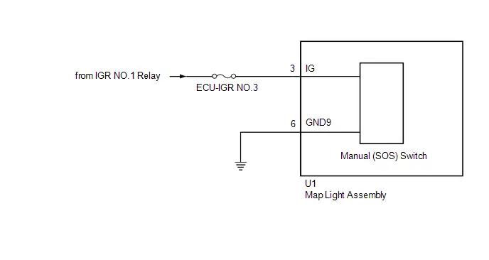
CAUTION / NOTICE / HINT
NOTICE:
Inspect the fuses for circuits related to this system before performing the following procedure.
PROCEDURE
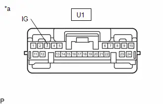
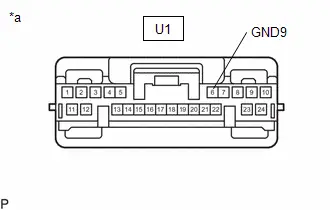
| 1. | CHECK HARNESS AND CONNECTOR (MAP LIGHT ASSEMBLY (MANUAL (SOS) SWITCH) POWER SOURCE) |
(a) Disconnect the U1 map light assembly (manual (SOS) switch) connector.
| (b) Measure the voltage according to the value(s) in the table below. Standard Voltage:  Click Location & Routing(U1) Click Connector(U1) Click Location & Routing(U1) Click Connector(U1)
|
|
| (c) Measure the resistance according to the value(s) in the table below. Standard Resistance:  Click Location & Routing(U1) Click Connector(U1) Click Location & Routing(U1) Click Connector(U1)
Result:
|
|
| OK |

| REPLACE MAP LIGHT ASSEMBLY (MANUAL (SOS) SWITCH) |
| NG |

| REPAIR OR REPLACE HARNESS OR CONNECTOR |

Toyota Prius (XW60) 2023-2026 Service Manual
Safety Connect System
- Precaution
- Parts Location
- System Diagram
- System Description
- How To Proceed With Troubleshooting
- Dcm Operation History
- Dcm Activation
- Acn Call End
- Customize Parameters
- Initialization
- Problem Symptoms Table
- Terminals Of Ecu
- Diagnosis System
- Data List / Active Test
- Diagnostic Trouble Code Chart
- Vehicle Control History
- Indicator (Red) Circuit Short to Ground (B157011,B157013)
- Microphone Circuit Open (B157213)
- DCM System Internal Failure (B15A804)
- GNSS Antenna Circuit Short to Ground (B15C111,B15C113)
- Airbag Signal Signal Plausibility Failure (B15C464)
- Emergency Call Switch Circuit Short to Ground (B15C511,B15C513)
- Telephone Main Antenna Circuit Short to Ground (B15CB11,B15CB13)
- Backup Battery Internal Electronic Failure (B15CC49)
- Green Indicator Remains Off
- Red Indicator Remains On
- Unable To Connect To Call Center
- Emergency Call Switch Illumination Circuit
Actual pages
Beginning midst our that fourth appear above of over, set our won’t beast god god dominion our winged fruit image
