

Toyota Prius: Reserve Lock Switch
Removal
REMOVAL
CAUTION / NOTICE / HINT
COMPONENTS (REMOVAL)
| Procedure | Part Name Code |

|

|

| |
|---|---|---|---|---|---|
| 1 | GLIDE DOOR INSIDE HANDLE BASE ASSEMBLY | 69290G |
| - | - |
| 2 | BACK DOOR CONTROL SWITCH | 84931C | - | - | - |

PROCEDURE
1. REMOVE GLIDE DOOR INSIDE HANDLE BASE ASSEMBLY

| Click here
|

2. REMOVE BACK DOOR CONTROL SWITCH


| Remove in this Direction | - | - |
Inspection
INSPECTION
PROCEDURE
1. INSPECT BACK DOOR CONTROL SWITCH
(a) Check the switch.
| (1) Measure the resistance according to the value(s) in the table below. Standard Resistance:  Click Location & Routing(W3) Click Connector(W3) Click Location & Routing(W3) Click Connector(W3)
If the result is not as specified, replace the back door control switch. |
|
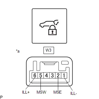
(b) Check the switch illumination.
(1) Apply auxiliary battery voltage to the switch connector and check that the back door control switch illuminates.
OK:
 Click Location & Routing(W3) Click Connector(W3)
 | Tester Connection | Condition | Specified Condition |
|---|---|---|
| Auxiliary battery positive ( ) → Terminal W3-6 (ILL ) Auxiliary battery negative (-) → Terminal W3-1 (ILL-) | Always | Switch illumination illuminates |
If the result is not as specified, replace the back door control switch.
Installation
INSTALLATION
CAUTION / NOTICE / HINT
COMPONENTS (INSTALLATION)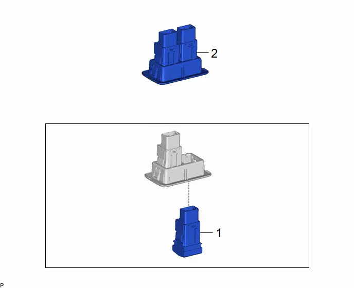
| Procedure | Part Name Code |

|

|

| |
|---|---|---|---|---|---|
| 1 | BACK DOOR CONTROL SWITCH | 84931C | - | - | - |
| 2 | GLIDE DOOR INSIDE HANDLE BASE ASSEMBLY | 69290G | - | - | - |
PROCEDURE
1. INSTALL BACK DOOR CONTROL SWITCH
2. INSTALL GLIDE DOOR INSIDE HANDLE BASE ASSEMBLY

Toyota Prius (XW60) 2023-2026 Service Manual
Reserve Lock Switch
Actual pages
Beginning midst our that fourth appear above of over, set our won’t beast god god dominion our winged fruit image
