

Toyota Prius: Rear Shock Absorber
Removal
REMOVAL
CAUTION / NOTICE / HINT
The necessary procedures (adjustment, calibration, initialization, or registration) that must be performed after parts are removed and installed, or replaced during rear shock absorber assembly removal/installation are shown below.
Necessary Procedures After Parts Removed/Installed/Replaced| Replaced Part or Performed Procedure | Necessary Procedure | Effect/Inoperative Function when Necessary Procedure not Performed | Link |
|---|---|---|---|
|
*1: Also necessary after performing a tire rotation.
*2: It is not necessary to perform this procedure if the tire pressure warning valve and transmitters are installed to the same location. *3: The Toyota Prius vehicle height changes because of suspension or tire replacement. | |||
| Rear wheel alignment adjustment | Perform "Calibration" |
|
|
| Tires |
| Tire Pressure Warning System | Refer to Procedures Necessary When Replacing Parts (for Tire Pressure Warning System)
|
| Rear television camera assembly optical axis (Back camera position setting)*3 | Parking Assist Monitor System |
| |
| Parking assist ECU initialization*3 | Panoramic View Monitor System |
| |
| Advanced Park |
| ||
| Suspension parts | Rear television camera assembly optical axis (Back camera position setting) | Parking Assist Monitor System |
|
| Parking assist ECU initialization | Panoramic View Monitor System |
| |
| Advanced Park |
| ||


CAUTION / NOTICE / HINT
HINT:
- Use the same procedure for the RH and LH sides.
- The following procedure is for the LH side.
CAUTION / NOTICE / HINT
COMPONENTS (REMOVAL)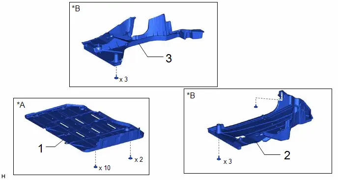
| Procedure | Part Name Code |

|

|

| |
|---|---|---|---|---|---|
| 1 | BATTERY BOX COVER | 58219K | - | - | - |
| 2 | REAR FLOOR SIDE MEMBER COVER LH | 57628E | - | - | - |
| 3 | REAR FLOOR SIDE MEMBER COVER RH | 57627G | - | - | - |
| *A | for PHEV Model | *B | for HEV Model |
| Procedure | Part Name Code |

|

|

| |
|---|---|---|---|---|---|
| 4 | REAR WHEEL | - | - | - | - |
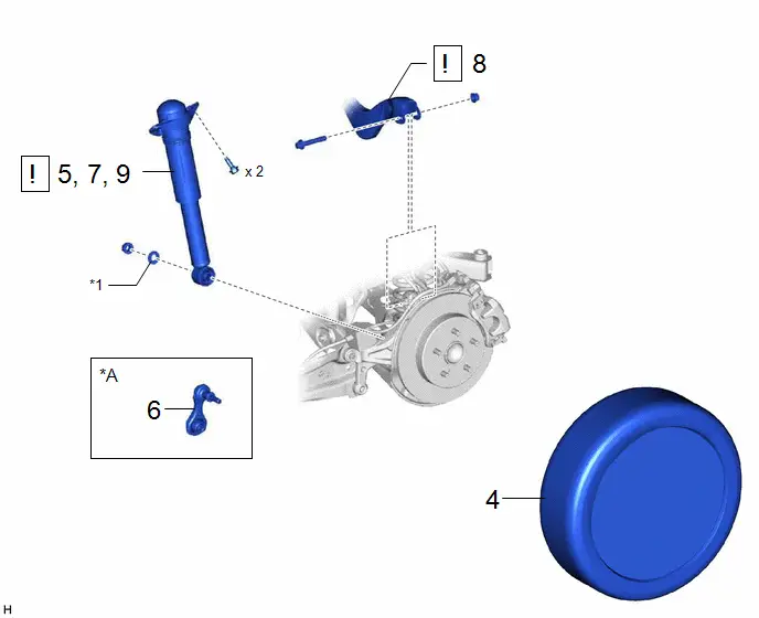
| 5 | LOOSEN REAR SHOCK ABSORBER ASSEMBLY | 48540 |
| - | - |
| 6 | REAR STABILIZER LINK ASSEMBLY | 48840A | - | - | - |
| 7 | SEPARATE REAR SHOCK ABSORBER ASSEMBLY | 48540 |
| - | - |
| 8 | REAR UPPER CONTROL ARM ASSEMBLY | 48790 |
| - | - |
| 9 | REMOVE REAR SHOCK ABSORBER ASSEMBLY | 48540 |
| - | - |


| *A | w/ Stabilizer Bar | - | - |
| *1 | PLATE WASHER | - | - |
| Procedure | Part Name Code |

|

|

| |
|---|---|---|---|---|---|
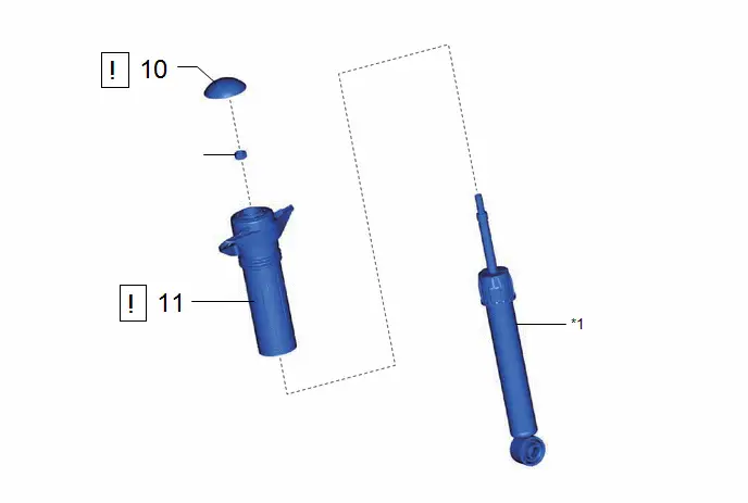
| 10 | REAR SHOCK ABSORBER CAP | 48554A |
| - | - |
| 11 | REAR SUSPENSION SUPPORT ASSEMBLY | 48760B |
| - | - |


| *1 | REAR SHOCK ABSORBER ASSEMBLY | - | - |
| ● | Non-reusable part | ★ | Precoated part |
PROCEDURE
1. REMOVE BATTERY BOX COVER (for PHEV Model)
Click here

2. REMOVE REAR FLOOR SIDE MEMBER COVER LH (for HEV Model)
Click here

3. REMOVE REAR FLOOR SIDE MEMBER COVER RH (for HEV Model)
Click here

4. REMOVE REAR WHEEL
Click here

5. LOOSEN REAR SHOCK ABSORBER ASSEMBLY

| *1 | Rear Axle Carrier Pin | - | - |
(1) Loosen the nut of the rear shock absorber assembly.
NOTICE:
Hold the rear axle carrier pin while rotating the nut.
6. REMOVE REAR STABILIZER LINK ASSEMBLY (w/ Stabilizer Bar)
Click here

7. SEPARATE REAR SHOCK ABSORBER ASSEMBLY
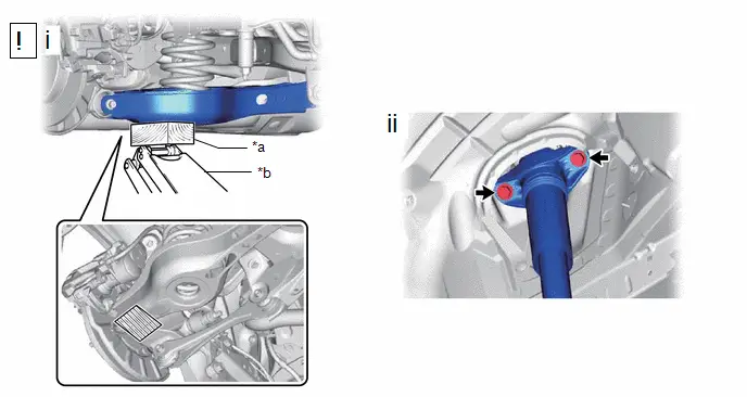
| *a | Wooden Block | *b | Jack |

| Wooden Block Placement Location | - | - |
(1) Using a jack and wooden block, support the rear No. 2 suspension arm assembly.
NOTICE:
- When jacking up the rear No. 2 suspension arm assembly, be sure to jack it up slowly.
- Make sure to perform this operation with the Toyota Prius vehicle kept as low as possible.
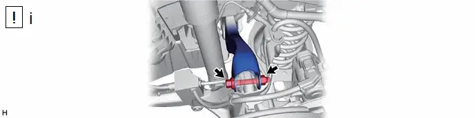
(2) Remove the 2 bolts and separate the rear shock absorber assembly from the vehicle.
8. SEPARATE REAR UPPER CONTROL ARM ASSEMBLY
(1) Remove the bolt and nut, and separate the rear upper control arm assembly from the rear axle carrier sub-assembly.
NOTICE:
Because the nut has its own stopper, do not turn the nut. Loosen the bolt with the nut secured.
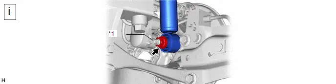
9. REMOVE REAR SHOCK ABSORBER ASSEMBLY
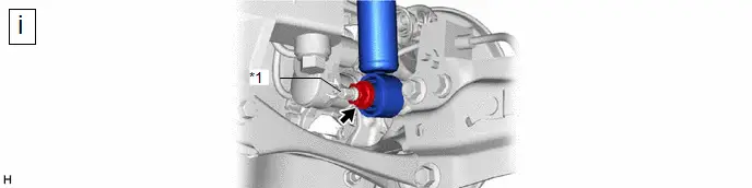
| *1 | Rear Axle Carrier Pin | - | - |
(1) Remove the nut, plate washer and rear shock absorber assembly from the rear axle carrier sub-assembly.
NOTICE:
Hold the rear axle carrier pin while rotating the nut.
10. REMOVE REAR SHOCK ABSORBER CAP
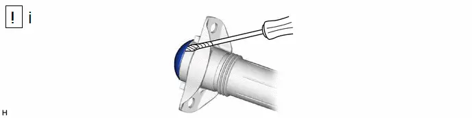
(1) Using a screwdriver with its tip wrapped with protective tape, remove the rear shock absorber cap from the rear shock absorber assembly.
11. REMOVE REAR SUSPENSION SUPPORT ASSEMBLY
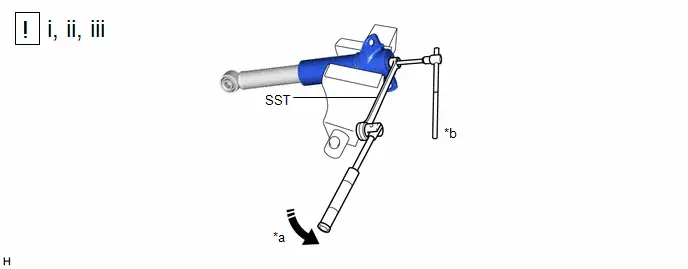
| *a | Turn | *b | Hold |
(1) Secure the rear shock absorber assembly in a vise using aluminum plates.
NOTICE:
Do not overtighten the vise.
(2) Using SST and a 6 mm hexagon socket wrench, hold the rear shock absorber rod and remove the rear support to rear shock absorber nut.
SST: 09729-00170
(3) Remove the rear suspension support assembly from the rear shock absorber assembly.
Inspection
INSPECTION
PROCEDURE
1. INSPECT REAR SHOCK ABSORBER ASSEMBLY
(a) Compress and extend the rear shock absorber assembly rod 4 or more times.
Standard:
When compressed and extended at a constant speed, the stroke of the shock absorber rod is smooth with no abnormal resistance or sounds. When extended, the shock absorber rod returns to its original position at a constant speed with no abnormal sounds.
(b) If there are any abnormalities, replace the rear shock absorber assembly with a new one.
Installation
INSTALLATION
CAUTION / NOTICE / HINT
HINT:
- Use the same procedure for the RH side and LH side.
- The following procedure is for the LH side.
CAUTION / NOTICE / HINT
COMPONENTS (INSTALLATION)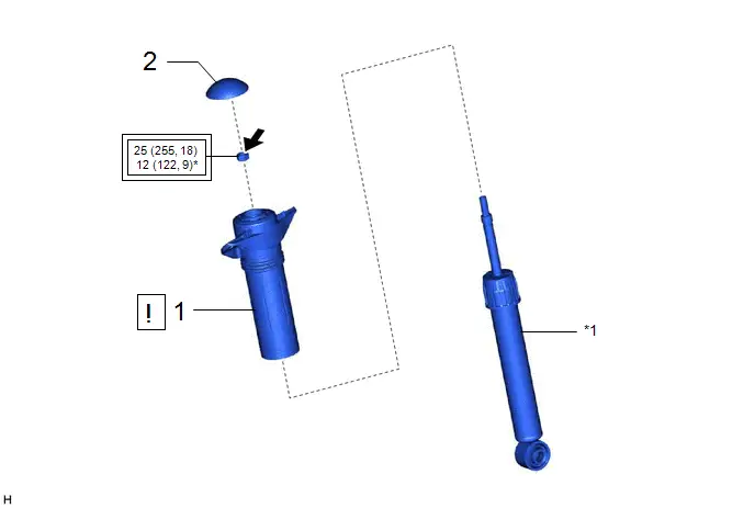
| Procedure | Part Name Code |

|

|

| |
|---|---|---|---|---|---|
| 1 | REAR SUSPENSION SUPPORT ASSEMBLY | 48760B |
| - | - |
| 2 | REAR SHOCK ABSORBER CAP | 48554A | - | - | - |

| *1 | REAR SHOCK ABSORBER ASSEMBLY | - | - |

| Tightening torque for "Major areas involving basic Toyota Prius vehicle performance such as moving/turning/stopping": N*m (kgf*cm, ft.*lbf) | * | For use with SST |
| ● | Non-reusable part |

| Adhesive 1324 |
| ★ | Precoated part | - | - |
| Procedure | Part Name Code |

|

|

| |
|---|---|---|---|---|---|
| 3 | TEMPORARILY INSTALL REAR SHOCK ABSORBER ASSEMBLY | 48540 |
| - | - |
| 4 | STABILIZE SUSPENSION | - |
| - | - |
| 5 | REAR UPPER CONTROL ARM ASSEMBLY | 48790 |
| - | - |
| 6 | CONNECT REAR SHOCK ABSORBER ASSEMBLY | 48540 |
| - | - |
| 7 | INSTALL REAR SHOCK ABSORBER ASSEMBLY | 48540 |
| - | - |
| 8 | REAR STABILIZER LINK ASSEMBLY (w/ Stabilizer Bar) | 48840A | - | - | - |
| 9 | REAR WHEEL | - | - | - | - |


| *A | w/ Stabilizer Bar | - | - |
| *1 | PLATE WASHER | - | - |

| Tightening torque for "Major areas involving basic Toyota Prius vehicle performance such as moving/turning/stopping": N*m (kgf*cm, ft.*lbf) | - | - |
| * | For use with a ball joint lock nut wrench | - | - |
| Procedure | Part Name Code |

|

|

| |
|---|---|---|---|---|---|
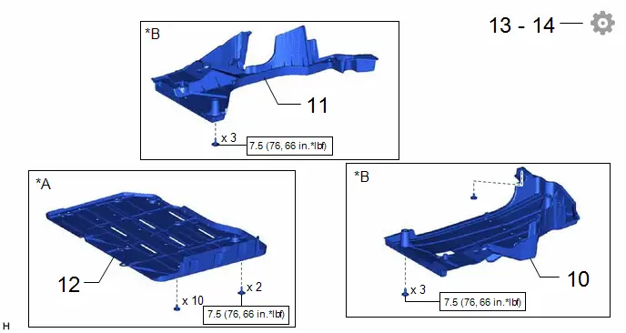
| 10 | REAR FLOOR SIDE MEMBER COVER LH | 57628E | - | - | - |
| 11 | REAR FLOOR SIDE MEMBER COVER RH | 57627G | - | - | - |
| 12 | BATTERY BOX COVER | 58219K | - | - | - |
| 13 | INSPECT AND ADJUST REAR WHEEL ALIGNMENT | - | - | - |
|
| 14 | PERFORM INITIALIZATION | - | - | - |
|


| *A | for PHEV Model | *B | for HEV Model |

| N*m (kgf*cm, ft.*lbf): Specified torque | - | - |
PROCEDURE
1. INSTALL REAR SUSPENSION SUPPORT ASSEMBLY
| *a | Torque Wrench Fulcrum Length | *b | Turn |
| *c | Hold | - | - |
(1) Secure the rear suspension support assembly in a vise using aluminum plates.
NOTICE:
Do not overtighten the vise.
(2) Install the rear suspension support assembly to the rear shock absorber assembly.
(3) Apply a few drops of adhesive to the threads of a new rear support to rear shock absorber nut.
Adhesive:
Toyota Genuine Adhesive 1324, Three Bond 1324 or equivalent
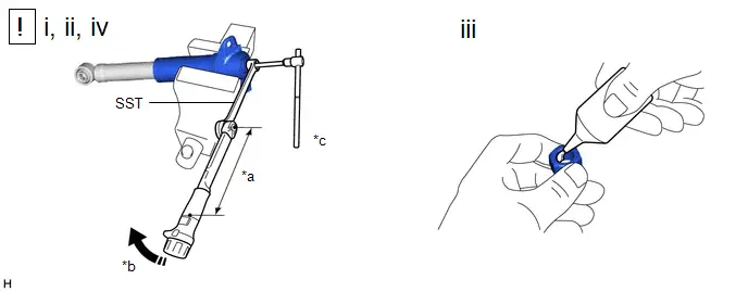
(4) Using SST and a 6 mm hexagon socket wrench, hold the rear shock absorber rod and tighten the rear support to rear shock absorber nut.
SST: 09729-00170
Torque:
Specified tightening torque :
25 N·m {255 kgf·cm, 18 ft·lbf}
NOTICE:
Securely insert the 6 mm hexagon socket wrench into the rear shock absorber rod to prevent damage to the rear shock absorber assembly when tightening the rear support to rear shock absorber nut.
HINT:
-
Calculate the torque wrench reading when changing the fulcrum length of the torque wrench.
Click here

-
When using SST (fulcrum length of 200 mm (7.87 in.)) torque wrench (fulcrum length of 180 mm (7.09 in.)):
12 N*m (122 kgf*cm, 9 ft.*lbf)
2. INSTALL REAR SHOCK ABSORBER CAP
3. TEMPORARILY INSTALL REAR SHOCK ABSORBER ASSEMBLY
| *1 | Rear Axle Carrier Pin | - | - |
(1) Temporarily install the rear shock absorber assembly to the rear axle carrier sub-assembly with the nut and plate washer.
NOTICE:
Hold the rear axle carrier pin while rotating the nut.
4. STABILIZE SUSPENSION

| CAUTION: Do not jack up the rear No. 2 suspension arm assembly too high as the Toyota Prius vehicle may fall. |
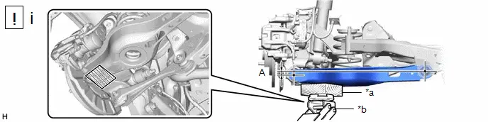
| *a | Wooden Block | *b | Jack |

| Wooden Block Placement Location | - | - |
(1) Using a jack and wooden block, apply load to the suspension so that the rear No. 2 suspension arm assembly is positioned as shown in the illustration.
Standard Length (A):
13 mm (0.512 in.)
NOTICE:
- When jacking up the rear No. 2 suspension arm assembly, be sure to jack it up slowly.
- Make sure to perform this operation with the Toyota Prius vehicle kept as low as possible.
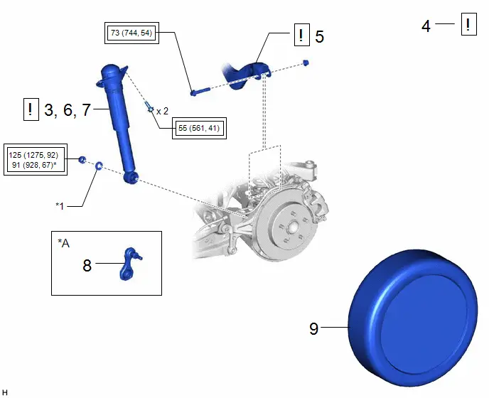
5. INSTALL REAR UPPER CONTROL ARM ASSEMBLY
(1) Install the rear upper control arm assembly to the rear axle carrier sub-assembly with the bolt and nut.
Torque:
73 N·m {744 kgf·cm, 54 ft·lbf}
NOTICE:
- Insert the bolt with the threaded end facing the rear of the Toyota Prius vehicle.
- Because the nut has its own stopper, do not turn the nut. Tighten the bolt with the nut secured.
6. CONNECT REAR SHOCK ABSORBER ASSEMBLY
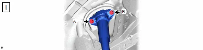
(1) Connect the rear shock absorber assembly to the vehicle with the 2 bolts.
Torque:
55 N·m {561 kgf·cm, 41 ft·lbf}
NOTICE:
Temporarily tighten the bolt (A) and then fully tighten the 2 bolts in the order of (B) and (A).
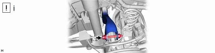
7. INSTALL REAR SHOCK ABSORBER ASSEMBLY
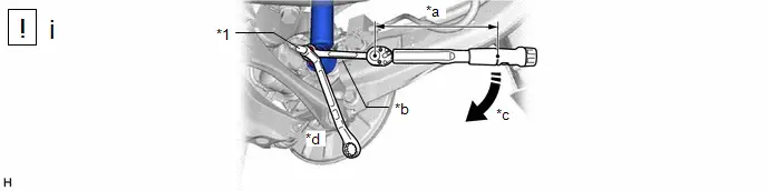
| *1 | Rear Axle Carrier Pin | - | - |
| *a | Torque Wrench Fulcrum Length | *b | Ball Joint Lock Nut Wrench |
| *c | Turn | *d | Hold |
(1) Using a ball joint lock nut wrench, fully tighten the rear shock absorber assembly with the nut.
Torque:
Specified tightening torque :
125 N·m {1275 kgf·cm, 92 ft·lbf}
NOTICE:
Hold the rear axle carrier pin while rotating the nut.
HINT:
-
Calculate the torque wrench reading when changing the fulcrum length of the torque wrench.
Click here

-
When using a ball joint lock nut wrench (fulcrum length of 149.75 mm (5.90 in.)) torque wrench (fulcrum length of 400 mm (1.31 ft.)):
91 N*m (928 kgf*cm, 67 ft.*lbf)
8. INSTALL REAR STABILIZER LINK ASSEMBLY (w/ Stabilizer Bar)
Click here

9. INSTALL REAR WHEEL
Click here

10. INSTALL REAR FLOOR SIDE MEMBER COVER LH (for HEV Model)
Click here

11. INSTALL REAR FLOOR SIDE MEMBER COVER RH (for HEV Model)
Click here

12. INSTALL BATTERY BOX COVER (for PHEV Model)
Click here

13. INSPECT AND ADJUST REAR WHEEL ALIGNMENT
Click here

14. PERFORM INITIALIZATION
| Parking Assist Monitor System |
|
| Panoramic View Monitor System |
|
| Advanced Park |
|


Disposal
DISPOSAL
PROCEDURE
1. DISPOSE OF REAR SHOCK ABSORBER ASSEMBLY
CAUTION:
- Always use a cloth to prevent shards of metal flying about due to the release of pressurized gas.
- Always wear safety glasses.
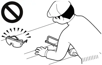
HINT:
The gas is colorless, odorless and non-poisonous.
| (a) Extend the piston rod and secure the rear shock absorber assembly at an angle in a vise. |
|
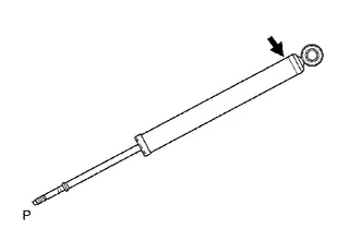
(b) Using a hacksaw, slowly make a hole at the position indicated by the arrow in the illustration to discharge the gas inside.

Toyota Prius (XW60) 2023-2026 Service Manual
Rear Shock Absorber
Actual pages
Beginning midst our that fourth appear above of over, set our won’t beast god god dominion our winged fruit image
