

Toyota Prius: Rear Lower Arm (for Awd Lh Side)
Removal
REMOVAL
CAUTION / NOTICE / HINT
The necessary procedures (adjustment, calibration, initialization, or registration) that must be performed after parts are removed and installed, or replaced during rear suspension member sub-assembly removal/installation are shown below.
Necessary Procedures After Parts Removed/Installed/Replaced| Replaced Part or Performed Procedure | Necessary Procedure | Effect/Inoperative Function when Necessary Procedure not Performed | Link |
|---|---|---|---|
|
*1: Also necessary after performing a tire rotation.
*2: It is not necessary to perform this procedure if the tire pressure warning valve and transmitters are installed to the same location. *3: The Toyota Prius vehicle height changes because of suspension or tire replacement. | |||
| Rear wheel alignment adjustment | Perform "Calibration" |
|
|
| Tires |
| Tire Pressure Warning System | Refer to Procedures Necessary When Replacing Parts (for Tire Pressure Warning System)
|
| Rear television camera assembly optical axis (Back camera position setting)*3 | Parking Assist Monitor System |
| |
| Parking assist ECU initialization*3 | Panoramic View Monitor System |
| |
| Advanced Park |
| ||
| Suspension parts | Rear television camera assembly optical axis (Back camera position setting) | Parking Assist Monitor System |
|
| Parking assist ECU initialization | Panoramic View Monitor System |
| |
| Advanced Park |
| ||
| Gas leak from exhaust system is repaired | Inspection after repair |
|
|


CAUTION / NOTICE / HINT
CAUTION:
-
Orange wire harnesses and connectors indicate high-voltage circuits. To prevent electric shock, always follow the procedure described in the repair manual.
Click here

-
To prevent electric shock, wear insulated gloves when working on wire harnesses and components of the high voltage system.
-
To prevent burns, do not touch the engine, exhaust pipe or other high temperature components while the engine is hot.
HINT:
When the cable is disconnected / reconnected to the auxiliary battery terminal, systems temporarily stop operating. However, each system has a function that completes learning the first time the system is used.
Learning completes when Toyota Prius vehicle is driven| Effect/Inoperative Function when Necessary Procedure not Performed | Necessary Procedure | Link |
|---|---|---|
| Front Camera System | Drive the Toyota Prius vehicle straight ahead at 35 km/h (22 mph) or more for 5 seconds or more. |
|

| Effect/Inoperative Function when Necessary Procedure not Performed | Necessary Procedure | Link |
|---|---|---|
|
*1: w/o Power Back Door System
*2: w/ Power Back Door System | ||
| Power Door Lock Control System*1
| Perform door unlock operation with door control switch or electrical key transmitter sub-assembly switch. |
|
| Power Back Door System*2 | Reset back door close position |
|
| Air Conditioning System | for HEV Model:
for PHEV Model:
| - |


CAUTION / NOTICE / HINT
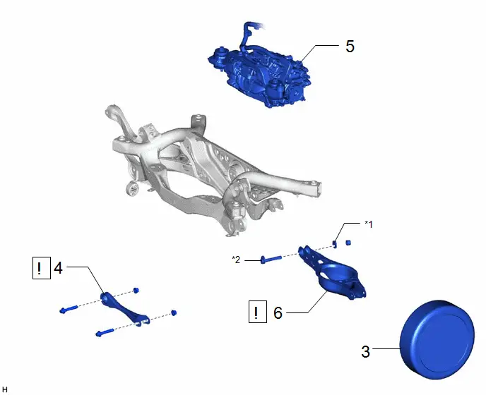
COMPONENTS (REMOVAL)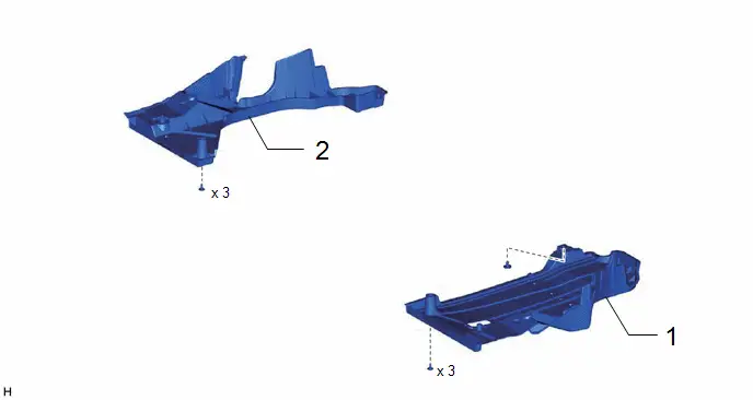
| Procedure | Part Name Code |

|

|

| |
|---|---|---|---|---|---|
| 1 | REAR FLOOR SIDE MEMBER COVER LH | 57628E | - | - | - |
| 2 | REAR FLOOR SIDE MEMBER COVER RH | 57627G | - | - | - |
| Procedure | Part Name Code |

|

|

| |
|---|---|---|---|---|---|
| 3 | REAR WHEEL | - | - | - | - |
| 4 | REAR NO. 1 SUSPENSION ARM ASSEMBLY | 48720A |
| - | - |
| 5 | REAR TRACTION MOTOR WITH TRANSAXLE ASSEMBLY | G1050 | - | - | - |
| 6 | REAR NO. 2 SUSPENSION ARM ASSEMBLY | 48740F |
| - | - |


| *1 | REAR SUSPENSION TOE ADJUST CAM SUB-ASSEMBLY | *2 | NO. 2 CAMBER ADJUST CAM |
PROCEDURE
1. REMOVE REAR FLOOR SIDE MEMBER COVER LH
Click here

2. REMOVE REAR FLOOR SIDE MEMBER COVER RH
Click here

3. REMOVE REAR WHEEL
Click here

4. REMOVE REAR NO. 1 SUSPENSION ARM ASSEMBLY
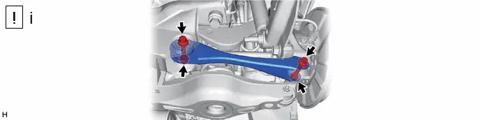
(1) Remove the 2 bolts, 2 nuts and rear No. 1 suspension arm assembly from the rear axle carrier sub-assembly and rear suspension member sub-assembly.
NOTICE:
Because the nut has its own stopper, do not turn the nut. Loosen the bolt with the nut secured.
5. REMOVE REAR TRACTION MOTOR WITH TRANSAXLE ASSEMBLY
Click here

6. REMOVE REAR NO. 2 SUSPENSION ARM ASSEMBLY
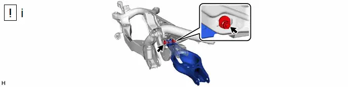
(1) Remove the nut, No. 2 camber adjust cam, rear suspension toe adjust cam sub-assembly and rear No. 2 suspension arm assembly.
NOTICE:
Hold the rear suspension toe adjust cam sub-assembly while rotating the nut.
Installation
INSTALLATION
CAUTION / NOTICE / HINT
COMPONENTS (INSTALLATION)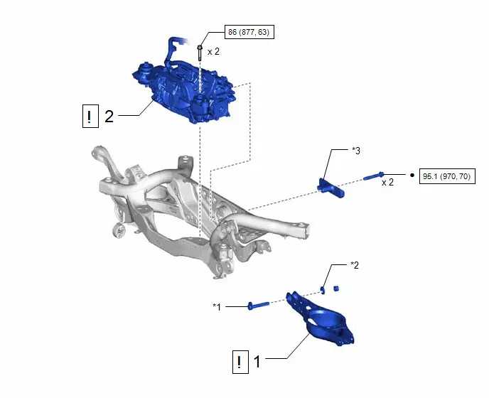
| Procedure | Part Name Code |

|

|

| |
|---|---|---|---|---|---|
| 1 | TEMPORARILY INSTALL REAR NO. 2 SUSPENSION ARM ASSEMBLY | 48740F |
| - | - |
| 2 | REAR TRACTION MOTOR WITH TRANSAXLE ASSEMBLY | G1050 |
| - | - |


| *1 | NO. 2 CAMBER ADJUST CAM | *2 | REAR SUSPENSION TOE ADJUST CAM SUB-ASSEMBLY |
| *3 | DIFFERENTIAL MASS DAMPER | - | - |

| N*m (kgf*cm, ft.*lbf): Specified torque | ● | Non-reusable part |
| Procedure | Part Name Code |

|

|

| |
|---|---|---|---|---|---|
| 3 | REAR TRACTION MOTOR CABLE | G1149 |
| - | - |
| 4 | NO. 6 FLOOR WIRE | 82169A | - | - | - |
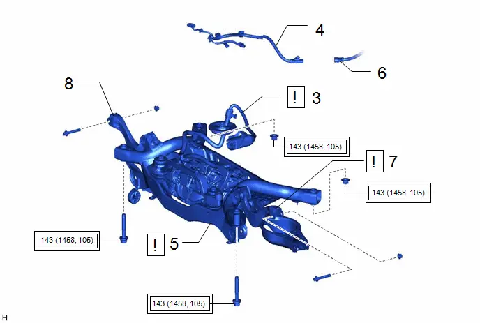
| 5 | REAR SUSPENSION MEMBER SUB-ASSEMBLY | 51206A |
| - | - |
| 6 | FRAME WIRE | - | - | - | - |
| 7 | REAR UPPER CONTROL ARM ASSEMBLY LH | 48790 |
| - | - |
| 8 | REAR UPPER CONTROL ARM ASSEMBLY RH | 48770A | - | - | - |


| Tightening torque for "Major areas involving basic Toyota Prius vehicle performance such as moving/turning/stopping": N*m (kgf*cm, ft.*lbf) | - | - |
| Procedure | Part Name Code |

|

|

| |
|---|---|---|---|---|---|
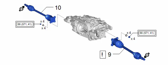
| 9 | REAR DRIVE SHAFT ASSEMBLY LH | 42340B |
| - | - |
| 10 | REAR DRIVE SHAFT ASSEMBLY RH | 42330 | - | - | - |


| Tightening torque for "Major areas involving basic Toyota Prius vehicle performance such as moving/turning/stopping": N*m (kgf*cm, ft.*lbf) |

| Do not apply lubricants to the threaded parts |
| Procedure | Part Name Code |

|

|

| |
|---|---|---|---|---|---|
| 11 | REAR NO. 1 SUSPENSION ARM ASSEMBLY LH | 48720A |
| - | - |
| 12 | REAR NO. 1 SUSPENSION ARM ASSEMBLY RH | 48710A | - | - | - |
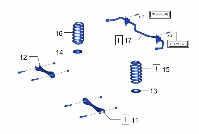
| 13 | REAR LOWER COIL SPRING INSULATOR LH | 48258C | - | - | - |
| 14 | REAR LOWER COIL SPRING INSULATOR RH | 48258B | - | - | - |
| 15 | REAR COIL SPRING LH | 48231B |
| - | - |
| 16 | REAR COIL SPRING RH | 48231A | - | - | - |
| 17 | REAR STABILIZER BAR | 48812 |
| - | - |


| Tightening torque for "Major areas involving basic Toyota Prius vehicle performance such as moving/turning/stopping": N*m (kgf*cm, ft.*lbf) | - | - |
| Procedure | Part Name Code |

|

|

| |
|---|---|---|---|---|---|
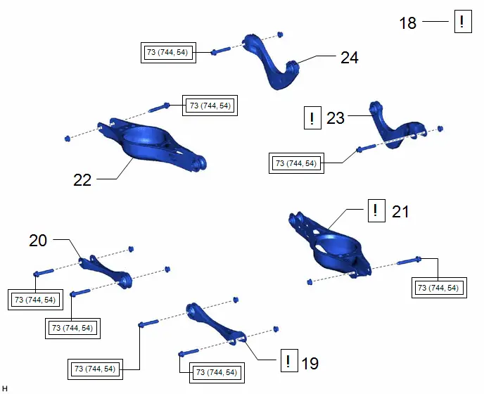
| 18 | STABILIZE SUSPENSION | - |
| - | - |
| 19 | REAR NO. 1 SUSPENSION ARM ASSEMBLY LH | 48720A |
| - | - |
| 20 | REAR NO. 1 SUSPENSION ARM ASSEMBLY RH | 48710A | - | - | - |
| 21 | REAR NO. 2 SUSPENSION ARM ASSEMBLY LH | 48740F |
| - | - |
| 22 | REAR NO. 2 SUSPENSION ARM ASSEMBLY RH | 48730F | - | - | - |
| 23 | REAR UPPER CONTROL ARM ASSEMBLY LH | 48790 |
| - | - |
| 24 | REAR UPPER CONTROL ARM ASSEMBLY RH | 48770A | - | - | - |


| Tightening torque for "Major areas involving basic Toyota Prius vehicle performance such as moving/turning/stopping": N*m (kgf*cm, ft.*lbf) | - | - |
| Procedure | Part Name Code |

|

|

| |
|---|---|---|---|---|---|
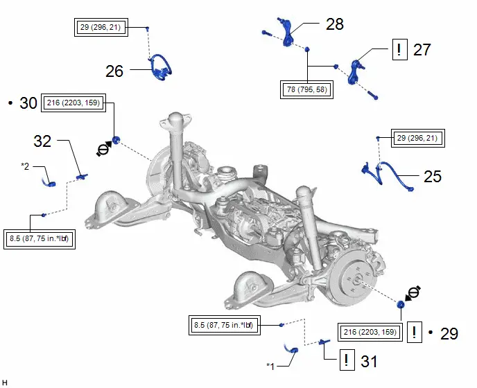
| 25 | REAR FLEXIBLE HOSE LH | 47319F | - | - | - |
| 26 | REAR FLEXIBLE HOSE RH | 47318F | - | - | - |
| 27 | REAR STABILIZER LINK ASSEMBLY LH | 48840A |
| - | - |
| 28 | REAR STABILIZER LINK ASSEMBLY RH | 48830D | - | - | - |
| 29 | REAR AXLE SHAFT NUT (for LH Side) | 42312B |
| - | - |
| 30 | REAR AXLE SHAFT NUT (for RH Side) | 42312B | - | - | - |
| 31 | REAR SKID CONTROL SENSOR LH | 89544E |
| - | - |
| 32 | REAR SKID CONTROL SENSOR RH | 89544D | - | - | - |


| *A | w/ Stabilizer Bar | - | - |
| *1 | NO. 2 PARKING BRAKE WIRE ASSEMBLY | ● | Non-reusable part |

| Tightening torque for "Major areas involving basic Toyota Prius vehicle performance such as moving/turning/stopping": N*m (kgf*cm, ft.*lbf) |

| Do not apply lubricants to the threaded parts |
| Procedure | Part Name Code |

|

|

| |
|---|---|---|---|---|---|
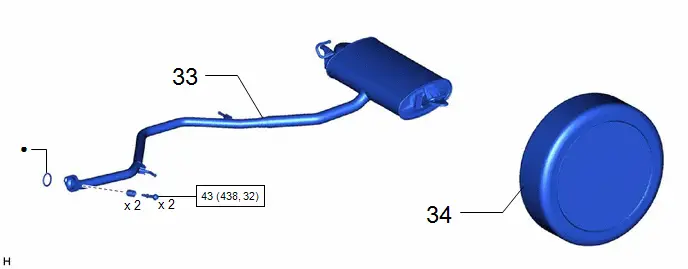
| 33 | TAIL EXHAUST PIPE ASSEMBLY | 17430 | - | - | - |
| 34 | REAR WHEEL | - | - | - | - |

| N*m (kgf*cm, ft.*lbf): Specified torque | ● | Non-reusable part |
| Procedure | Part Name Code |

|

|

| |
|---|---|---|---|---|---|
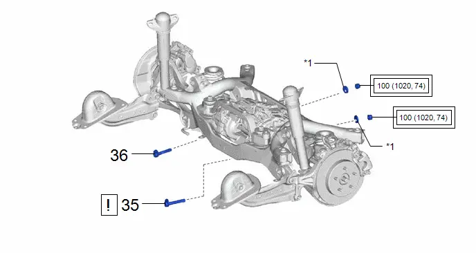
| 35 | REAR SUSPENSION TOE ADJUST CAM SUB-ASSEMBLY (for LH Side) | 48409 |
| - | - |
| 36 | REAR SUSPENSION TOE ADJUST CAM SUB-ASSEMBLY (for RH Side) | 48409 | - | - | - |

| *1 | NO. 2 CAMBER ADJUST CAM | - | - |

| Tightening torque for "Major areas involving basic Toyota Prius vehicle performance such as moving/turning/stopping": N*m (kgf*cm, ft.*lbf) | - | - |
| Procedure | Part Name Code |

|

|

| |
|---|---|---|---|---|---|
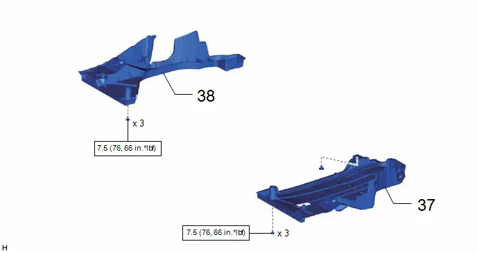
| 37 | REAR FLOOR SIDE MEMBER COVER LH | 57628E | - | - | - |
| 38 | REAR FLOOR SIDE MEMBER COVER RH | 57627G | - | - | - |

| Procedure | Part Name Code |

|

|

| |
|---|---|---|---|---|---|
| 39 | REAR TRACTION MOTOR CABLE | G1149 |
| - | - |
| 40 | DECK FLOOR BOX LH | 64997 | - | - | - |
| 41 | DECK FLOOR BOX RH | 64995 | - | - | - |
| 42 | DECK BOARD ASSEMBLY | 58410B | - | - | - |

| *A | for Type A | *B | for Type B |
| *C | w/o Spare Tire | *D | w/ Spare Tire |
| Procedure | Part Name Code |

|

|

| |
|---|---|---|---|---|---|
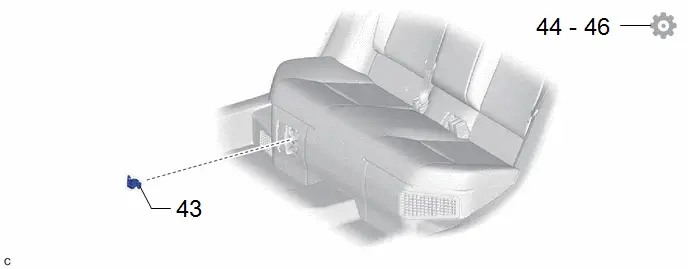
| 43 | SERVICE PLUG GRIP | G3834 | - | - | - |
| 44 | INSPECT FOR EXHAUST GAS LEAK | - | - | - |
|
| 45 | INSPECT AND ADJUST REAR WHEEL ALIGNMENT | - | - | - |
|
| 46 | PERFORM INITIALIZATION | - | - | - |
|


PROCEDURE
1. TEMPORARILY INSTALL REAR NO. 2 SUSPENSION ARM ASSEMBLY

(1) Temporarily install the rear No. 2 suspension arm assembly to the rear suspension member sub-assembly with the No. 2 camber adjust cam, rear suspension toe adjust cam sub-assembly and nut.
NOTICE:
- Insert the rear suspension toe adjust cam sub-assembly from the front of the Toyota Prius vehicle.
- When tightening the nut, keep the rear suspension toe adjust cam sub-assembly from rotating.
2. INSTALL REAR TRACTION MOTOR WITH TRANSAXLE ASSEMBLY

| Click here
|

3. CONNECT REAR TRACTION MOTOR CABLE
Click here

4. INSTALL NO. 6 FLOOR WIRE
Click here

5. INSTALL REAR SUSPENSION MEMBER SUB-ASSEMBLY

| Click here
|

6. INSTALL FRAME WIRE
7. TEMPORARILY INSTALL REAR UPPER CONTROL ARM ASSEMBLY LH
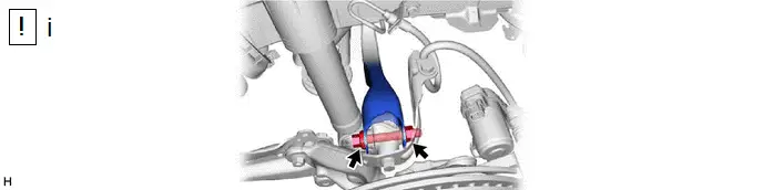
(1) Temporarily install the rear upper control arm assembly LH to the rear axle carrier sub-assembly LH with the bolt and nut.
NOTICE:
- Insert the bolt with the threaded end facing the rear of the Toyota Prius vehicle.
- Because the nut has its own stopper, do not turn the nut. Tighten the bolt with the nut secured.
8. TEMPORARILY INSTALL REAR UPPER CONTROL ARM ASSEMBLY RH
9. INSTALL REAR DRIVE SHAFT ASSEMBLY LH

| Click here
|

10. INSTALL REAR DRIVE SHAFT ASSEMBLY RH
11. TEMPORARILY INSTALL REAR NO. 1 SUSPENSION ARM ASSEMBLY LH

(1) Temporarily install the rear No. 1 suspension arm assembly to the rear axle carrier sub-assembly and rear suspension member sub-assembly with the 2 bolts and 2 nuts.
NOTICE:
- Because the nut has its own stopper, do not turn the nut. Tighten the bolt with the nut secured.
- Insert the bolt with the threaded end facing the rear of the Toyota Prius vehicle.
12. TEMPORARILY INSTALL REAR NO. 1 SUSPENSION ARM ASSEMBLY RH
13. INSTALL REAR LOWER COIL SPRING INSULATOR LH
14. INSTALL REAR LOWER COIL SPRING INSULATOR RH
15. INSTALL REAR COIL SPRING LH

| Click here
|


16. INSTALL REAR COIL SPRING RH
17. INSTALL REAR STABILIZER BAR

| Click here
|


18. STABILIZE SUSPENSION

| Click here
|


19. INSTALL REAR NO. 1 SUSPENSION ARM ASSEMBLY LH
(1) Install the rear No. 1 suspension arm assembly with the 2 bolts.
Torque:
73 N·m {744 kgf·cm, 54 ft·lbf}
NOTICE:
Because the nut has its own stopper, do not turn the nut. Tighten the bolt with the nut secured.
20. INSTALL REAR NO. 1 SUSPENSION ARM ASSEMBLY RH
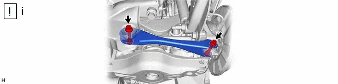
21. INSTALL REAR NO. 2 SUSPENSION ARM ASSEMBLY LH

(1) Install the rear No. 2 suspension arm assembly (rear axle carrier sub-assembly side) with the bolt.
Torque:
73 N·m {744 kgf·cm, 54 ft·lbf}
NOTICE:
Because the nut has its own stopper, do not turn the nut. Tighten the bolt with the nut secured.
22. INSTALL REAR NO. 2 SUSPENSION ARM ASSEMBLY RH
23. INSTALL REAR UPPER CONTROL ARM ASSEMBLY LH

| Click here
|


24. INSTALL REAR UPPER CONTROL ARM ASSEMBLY RH
25. INSTALL REAR FLEXIBLE HOSE LH
Click here

26. INSTALL REAR FLEXIBLE HOSE RH
27. INSTALL REAR STABILIZER LINK ASSEMBLY LH

| Click here
|


28. INSTALL REAR STABILIZER LINK ASSEMBLY RH
29. INSTALL REAR AXLE SHAFT NUT (for LH Side)

| Click here
|

30. INSTALL REAR AXLE SHAFT NUT (for RH Side)
31. INSTALL REAR SKID CONTROL SENSOR LH

| Click here
|

32. INSTALL REAR SKID CONTROL SENSOR RH
33. INSTALL TAIL EXHAUST PIPE ASSEMBLY
Click here


34. INSTALL REAR WHEEL
Click here

35. INSTALL REAR SUSPENSION TOE ADJUST CAM SUB-ASSEMBLY (for LH Side)
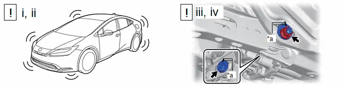
| *a | Matchmark | - | - |
(1) Lower the Toyota Prius vehicle to the ground.
(2) Bounce the vehicle up and down at the corners to stabilize the rear suspension.
(3) Align the matchmarks on the No. 2 camber adjust cam, rear suspension toe adjust cam sub-assembly and rear suspension member sub-assembly.
(4) Fully tighten the nut.
Torque:
100 N·m {1020 kgf·cm, 74 ft·lbf}
NOTICE:
- Hold the rear suspension toe adjust cam sub-assembly while rotating the nut.
- Make sure that the Toyota Prius vehicle is unloaded when fully tightening the nut.
36. INSTALL REAR SUSPENSION TOE ADJUST CAM SUB-ASSEMBLY (for RH Side)
Click here

37. INSTALL REAR FLOOR SIDE MEMBER COVER LH
Click here


38. INSTALL REAR FLOOR SIDE MEMBER COVER RH
Click here


39. CONNECT REAR TRACTION MOTOR CABLE

| Click here
|

40. INSTALL DECK FLOOR BOX LH
41. INSTALL DECK FLOOR BOX RH
42. INSTALL DECK BOARD ASSEMBLY
43. INSTALL SERVICE PLUG GRIP
Click here

44. INSPECT FOR EXHAUST GAS LEAK
Click here


45. INSPECT AND ADJUST REAR WHEEL ALIGNMENT
Click here


46. PERFORM INITIALIZATION
| Parking Assist Monitor System |
|
| Panoramic View Monitor System |
|
| Advanced Park |
|


Toyota Prius (XW60) 2023-2026 Service Manual
Rear Lower Arm (for Awd Lh Side)
Actual pages
Beginning midst our that fourth appear above of over, set our won’t beast god god dominion our winged fruit image
