

Toyota Prius: Rear Drive Shaft Assembly
Removal
REMOVAL
CAUTION / NOTICE / HINT
The necessary procedures (adjustment, calibration, initialization, or registration) that must be performed after parts are removed and installed, or replaced during rear drive shaft assembly removal/installation are shown below.
CAUTION / NOTICE / HINT
Necessary Procedures After Parts Removed/Installed/Replaced|
Replaced Part or Performed Procedure |
Necessary Procedure |
Effect/Inoperative Function when Necessary Procedure not Performed |
Link |
|---|---|---|---|
| *1: Also necessary after performing a tire rotation.
*2: It is not necessary to perform this procedure if the tire pressure warning valve and transmitters are installed to the same location. *3: The Toyota Prius vehicle height changes because of tire replacement. |
|||
|
Rear wheel alignment adjustment |
Perform "Calibration" |
|
|
|
Tires |
|
Tire Pressure Warning System |
Refer to Procedures Necessary When Replacing Parts (for Tire Pressure Warning System)
|
|
Rear television camera assembly optical axis (Back camera position setting)*3 |
Parking Assist Monitor System |
|
|
|
Parking assist ECU initialization*3 |
Panoramic View Monitor System |
|
|
|
Advanced Park |
|
||
|
Suspension parts |
Rear television camera assembly optical axis (Back camera position setting) |
Parking Assist Monitor System |
|
|
Parking assist ECU initialization |
Panoramic View Monitor System |
|
|
|
Advanced Park |
|
||


CAUTION / NOTICE / HINT
HINT:
- Use the same procedure for the RH side and LH side.
- The following procedure is for the LH side.
CAUTION / NOTICE / HINT
COMPONENTS (REMOVAL)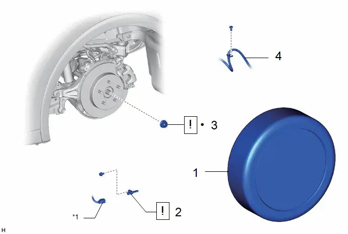
|
Procedure |
Part Name Code |
 |
 |
 |
|
|---|---|---|---|---|---|
|
1 |
REAR WHEEL |
- |
- |
- |
- |
|
2 |
REAR SKID CONTROL SENSOR |
89544E |
|
- |
- |
|
3 |
REAR AXLE SHAFT NUT |
42312B |
|
- |
- |
|
4 |
REAR FLEXIBLE HOSE |
47319F |
- |
- |
- |


|
*1 |
NO. 2 PARKING BRAKE WIRE ASSEMBLY |
- |
- |
|
● |
Non-reusable part |
- |
- |
|
Procedure |
Part Name Code |
 |
 |
 |
|
|---|---|---|---|---|---|
|
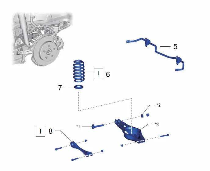
5 |
REAR STABILIZER BAR |
48812 |
- |
- |
- |
|
6 |
REAR COIL SPRING |
48231B |
|
- |
- |
|
7 |
REAR LOWER COIL SPRING INSULATOR |
48258C |
- |
- |
- |
|
8 |
REAR NO. 1 SUSPENSION ARM ASSEMBLY |
48720A |
|
- |
- |


|
*1 |
REAR SUSPENSION TOE ADJUST CAM SUB-ASSEMBLY |
*2 |
NO. 2 CAMBER ADJUST CAM |
|
*3 |
REAR NO. 2 SUSPENSION ARM ASSEMBLY |
- |
- |
|
Procedure |
Part Name Code |
 |
 |
 |
|
|---|---|---|---|---|---|
|
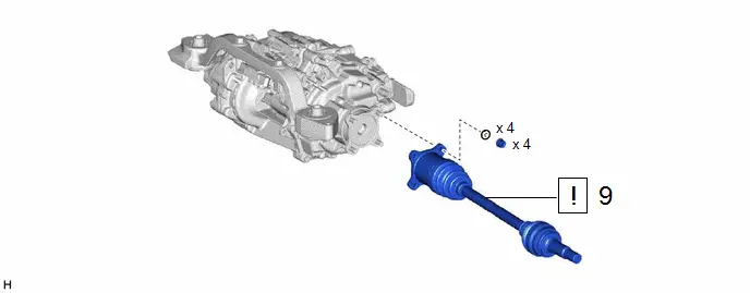
9 |
REAR DRIVE SHAFT ASSEMBLY |
42340B |
|
- |
- |

PROCEDURE
1. REMOVE REAR WHEEL
Click here

2. REMOVE REAR SKID CONTROL SENSOR
 |
Click here
|

3. REMOVE REAR AXLE SHAFT NUT
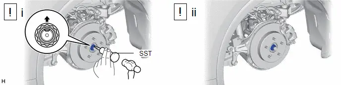
(1) Using SST and a hammer, release the staked part of the rear axle shaft nut.
SST: 09930-00010
NOTICE:
Loosen the staked part of the rear axle shaft nut completely, otherwise the threads of the rear drive shaft assembly may be damaged.
(2) Using a 30 mm deep socket wrench, remove the rear axle shaft nut while applying the brakes.
4. SEPARATE REAR FLEXIBLE HOSE
Click here


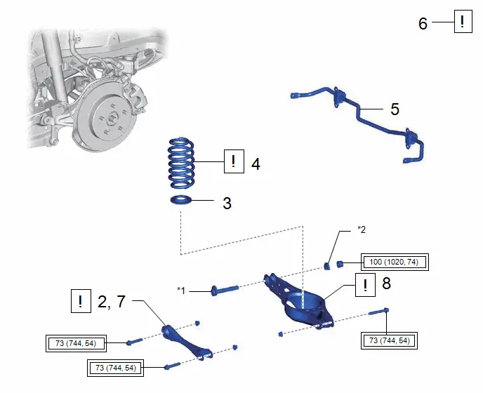
5. REMOVE REAR STABILIZER BAR
Click here


6. REMOVE REAR COIL SPRING
 |
Click here
|


7. REMOVE REAR LOWER COIL SPRING INSULATOR
Click here


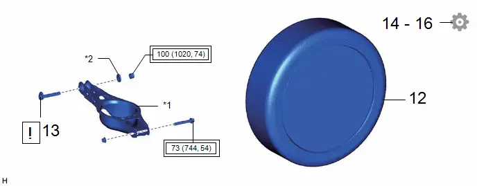
8. REMOVE REAR NO. 1 SUSPENSION ARM ASSEMBLY
 |
for AWD LH Side: Click here
for AWD RH Side: Click here
|


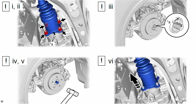
9. REMOVE REAR DRIVE SHAFT ASSEMBLY
|
*a |
Matchmark |
- |
- |
 |
Remove in this Direction |
- |
- |
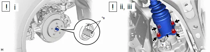
(1) Put matchmarks on the rear drive shaft assembly and differential side gear shaft sub-assembly.
(2) Remove the 4 nuts and 4 washers.
(3) Put matchmarks on the rear drive shaft assembly and the rear axle hub and bearing assembly.
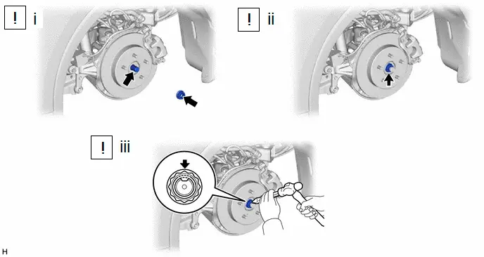
(4) Using a plastic hammer, separate the rear drive shaft assembly from the rear axle hub and bearing assembly.
NOTICE:
- Do not damage the rear drive shaft outboard joint boot.
- Do not drop the rear drive shaft assembly.
(5) If it is difficult to separate the rear drive shaft assembly from the rear axle hub and bearing assembly, tap the end of the rear drive shaft assembly using a brass bar and a hammer.
(6) Push the rear drive shaft inboard joint assembly toward the outside of the Toyota Prius vehicle and remove the rear drive shaft assembly from the differential side gear shaft sub-assembly.
NOTICE:
Do not damage the rear drive shaft inboard joint boot.
Disassembly
DISASSEMBLY
CAUTION / NOTICE / HINT
NOTICE:
- When using a vise, place aluminum plates between the part and vise.
- When using a vise, do not overtighten it.
HINT:
- Use the same procedure for the RH side and LH side.
- The following procedure is for the LH side.
CAUTION / NOTICE / HINT
COMPONENTS (DISASSEMBLY)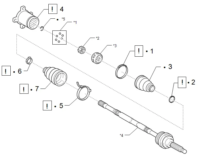
|
Procedure |
Part Name Code |
 |
 |
 |
|
|---|---|---|---|---|---|
|
1 |
REAR NO. 2 DRIVE SHAFT INBOARD JOINT BOOT CLAMP |
42347F |
|
- |
- |
|
2 |
REAR DRIVE SHAFT INBOARD JOINT BOOT CLAMP |
42347D |
|
- |
- |
|
3 |
REAR DRIVE SHAFT INBOARD JOINT BOOT |
- |
- |
- |
- |
|
4 |
REAR DRIVE SHAFT INBOARD JOINT ASSEMBLY |
42360D |
|
- |
- |
|
5 |
REAR NO. 2 DRIVE SHAFT OUTBOARD JOINT BOOT CLAMP |
42346F |
|
- |
- |
|
6 |
REAR DRIVE SHAFT OUTBOARD JOINT BOOT CLAMP |
42346D |
|
- |
- |
|
7 |
REAR DRIVE SHAFT OUTBOARD JOINT BOOT |
- |
|
- |
- |


|
*1 |
BALL |
*2 |
INNER RACE |
|
*3 |
BALL CAGE |
*4 |
REAR DRIVE SHAFT OUTBOARD JOINT SHAFT ASSEMBLY |
|
*5 |
SHAFT SNAP RING |
- |
- |
|
● |
Non-reusable part |
- |
- |
PROCEDURE
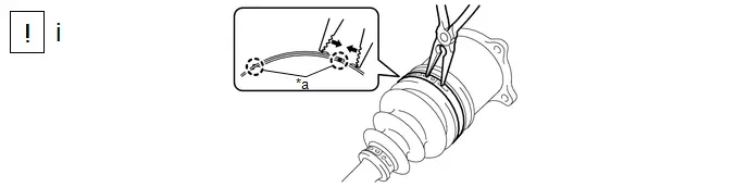
1. SEPARATE REAR NO. 2 DRIVE SHAFT INBOARD JOINT BOOT CLAMP
|
*a |
Claw |
- |
- |
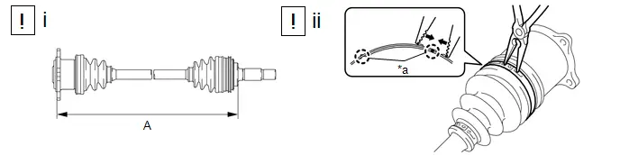
(1) Using needle-nose pliers, disengage the 2 claws as shown in the illustration and separate the rear No. 2 drive shaft inboard joint boot clamp.
2. SEPARATE REAR DRIVE SHAFT INBOARD JOINT BOOT CLAMP
(a) Perform the same procedure as for the rear No. 2 drive shaft inboard joint boot clamp.
3. SEPARATE REAR DRIVE SHAFT INBOARD JOINT BOOT

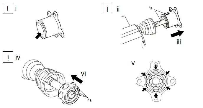
4. REMOVE REAR DRIVE SHAFT INBOARD JOINT ASSEMBLY
|
*a |
Matchmark |
- |
- |
(1) Remove the old grease from the rear drive shaft inboard joint assembly.
(2) Put matchmarks on the rear drive shaft inboard joint assembly and rear drive shaft outboard joint shaft assembly.
NOTICE:
Do not use a punch for the marks.
(3) Remove the rear drive shaft inboard joint assembly from the rear drive shaft outboard joint shaft assembly.
NOTICE:
Be careful not to drop the balls.
(4) Put matchmarks on the rear drive shaft outboard joint shaft assembly, inner race and ball cage.
NOTICE:
Do not use a punch for the marks.
(5) Remove the 6 balls.
(6) Slide the ball cage to the outboard Joint Side.
(1) Using a snap ring expander, remove the shaft snap ring from the rear drive shaft outboard joint shaft assembly.
(2) Using a brass bar and a hammer, tap out the inner race from the rear drive shaft outboard joint shaft assembly.
Be careful not to damage the inner race.
NOTICE:
Be careful not to damage the inner race.
(3) Remove the ball cage.
(4) Remove the rear No. 2 drive shaft inboard joint boot clamp, rear drive shaft inboard joint boot and rear drive shaft inboard joint boot clamp.
5. SEPARATE REAR NO. 2 DRIVE SHAFT OUTBOARD JOINT BOOT CLAMP
(1) Using a screwdriver, separate the rear No. 2 drive shaft outboard joint boot clamp as shown in the illustration.
6. SEPARATE REAR DRIVE SHAFT OUTBOARD JOINT BOOT CLAMP
(1) Using pliers, separate the rear drive shaft outboard joint boot clamp as shown in the illustration.
7. REMOVE REAR DRIVE SHAFT OUTBOARD JOINT BOOT
(1) Remove the rear drive shaft outboard joint boot clamp, rear drive shaft outboard joint boot and rear No. 2 drive shaft outboard joint boot clamp from the rear drive shaft outboard joint shaft assembly.
(2) Remove the old grease from the outboard joint.
Inspection
INSPECTION
PROCEDURE
1. INSPECT REAR DRIVE SHAFT ASSEMBLY
|
(a) Check that there is no excessive play in the radial direction of the outboard joint. |
|
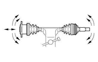
(b) Check that the inboard joint slides smoothly in the thrust direction.
(c) Check that there is no excessive play in the radial direction of the inboard joint.
(d) Check the boots for damage.
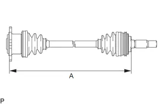
|
(e) Check whether each drive shaft dimension (A) is within specification. NOTICE: Keep the drive shaft assembly level during inspection. Dimension (A)
|
|
Reassembly
REASSEMBLY
CAUTION / NOTICE / HINT
NOTICE:
- When using a vise, place aluminum plates between the part and vise.
- When using a vise, do not overtighten it.
HINT:
- Use the same procedure for the RH side and LH side.
- The following procedure is for the LH side.
CAUTION / NOTICE / HINT
COMPONENTS (REASSEMBLY)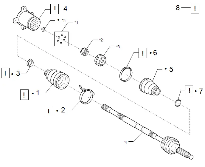
|
Procedure |
Part Name Code |
 |
 |
 |
|
|---|---|---|---|---|---|
|
1 |
REAR DRIVE SHAFT OUTBOARD JOINT BOOT |
- |
|
- |
- |
|
2 |
REAR NO. 2 DRIVE SHAFT OUTBOARD JOINT BOOT CLAMP |
42346F |
|
- |
- |
|
3 |
REAR DRIVE SHAFT OUTBOARD JOINT BOOT CLAMP |
42346D |
|
- |
- |
|
4 |
REAR DRIVE SHAFT INBOARD JOINT ASSEMBLY |
42360D |
|
- |
- |
|
5 |
REAR DRIVE SHAFT INBOARD JOINT BOOT |
- |
- |
- |
- |
|
6 |
REAR NO. 2 DRIVE SHAFT INBOARD JOINT BOOT CLAMP |
42347F |
|
- |
- |
|
7 |
REAR DRIVE SHAFT INBOARD JOINT BOOT CLAMP |
42347D |
|
- |
- |
|
8 |
REAR DRIVE SHAFT ASSEMBLY |
42340B |
|
- |
- |


|
*1 |
BALL |
*2 |
INNER RACE |
|
*3 |
BALL CAGE |
*4 |
REAR DRIVE SHAFT OUTBOARD JOINT SHAFT ASSEMBLY |
|
*5 |
SHAFT SNAP RING |
- |
- |
|
● |
Non-reusable part |
- |
- |
PROCEDURE
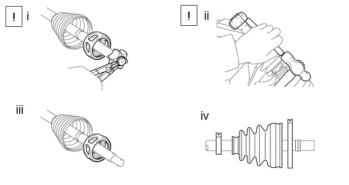
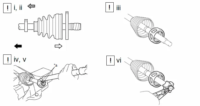
1. INSTALL REAR DRIVE SHAFT OUTBOARD JOINT BOOT
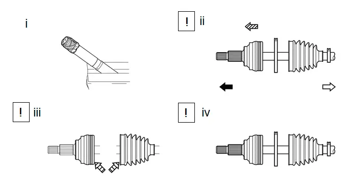
 |
Outboard Joint Side |
 |
Inboard Joint Side |
 |
Parts insertion direction |
 |
Grease |
(1) Wrap the splines of the rear drive shaft outboard joint shaft assembly with protective tape to prevent the boot from being damaged.
(2) Install new parts to the rear drive shaft outboard joint shaft assembly in the following order:
1. Rear No. 2 drive shaft outboard joint boot clamp
2. Rear drive shaft outboard joint boot
3. Rear drive shaft outboard joint boot clamp
(3) Pack the joint portion of the rear drive shaft outboard joint shaft assembly and rear drive shaft outboard joint boot with grease.
Standard Grease Capacity:
37 to 47 g (1.31 to 1.66 oz.)
(4) Install the rear drive shaft outboard joint boot to the rear drive shaft outboard joint shaft assembly groove.
NOTICE:
- Do not allow grease to adhere to the boot clamp track of the outboard joint boot.
- Keep the inside of the outboard joint boot free of foreign matter.
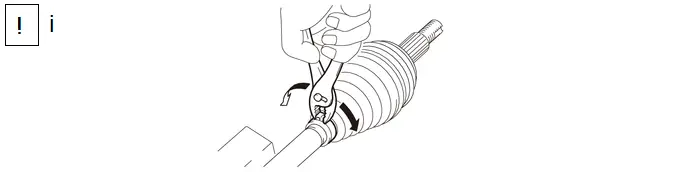
2. INSTALL REAR NO. 2 DRIVE SHAFT OUTBOARD JOINT BOOT CLAMP
(1) Using a screwdriver, install the rear No. 2 drive shaft outboard joint boot clamp as shown in the illustration.
NOTICE:
Be careful not to damage the rear drive shaft outboard joint boot.
3. INSTALL REAR DRIVE SHAFT OUTBOARD JOINT BOOT CLAMP
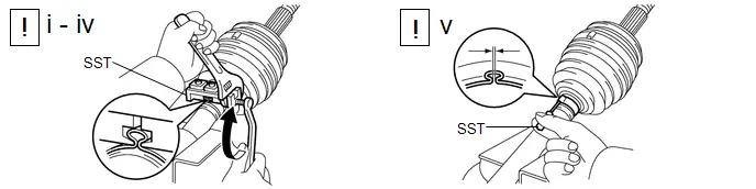
(1) Install the rear drive shaft outboard joint boot clamp to the rear drive shaft outboard joint boot.
(2) Place SST onto the rear drive shaft outboard joint boot clamp, press it against the boot and slightly tighten SST.
SST: 09521-24010
(3) Tighten SST so that the rear drive shaft outboard joint boot clamp is pinched.
NOTICE:
Do not overtighten SST.
(4) Remove SST.
(5) Using SST, measure the clearance of the rear drive shaft outboard joint boot clamp.
SST: 09240-00021
Clearance:
1.2 mm (0.0472 in.) or less
If the clearance is not as specified, retighten SST.
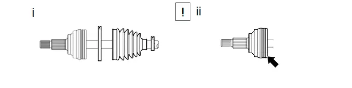
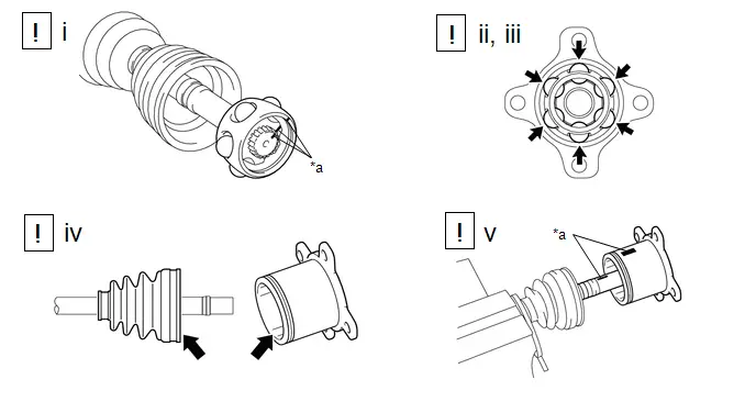
4. INSTALL REAR DRIVE SHAFT INBOARD JOINT ASSEMBLY
|
*a |
Matchmark |
- |
- |
 |
Outboard Joint Side |
 |
Inboard Joint Side |
 |
Parts insertion direction |
- |
- |
(1) Install new parts to the rear drive shaft outboard joint shaft assembly in the following order:
1. Rear drive shaft inboard joint boot clamp
2. Rear drive shaft inboard joint boot
3. Rear No. 2 drive shaft inboard joint boot clamp
(2) Remove the protective tape.
(3) Install the ball cage to the rear drive shaft outboard joint shaft assembly.
NOTICE:
Face the smaller inside diameter side to the rear drive shaft outboard joint shaft assembly.
(4) Align the matchmarks placed before removal.
(5) Using a brass bar and a hammer, install the inner race to the rear drive shaft outboard joint shaft assembly.
NOTICE:
Be careful not to damage the inner race.
(6) Using a snap ring expander, install a new shaft snap ring to the rear drive shaft outboard joint shaft assembly.
|
*a |
Matchmark |
- |
- |
 |
Grease |
- |
- |
(1) Align the matchmarks and install the ball cage to the inner race.
(2) Apply grease to the balls to keep them from falling.
(3) Install the 6 balls with grease to the inner race.
NOTICE:
Be careful not to drop the balls.
(4) Pack the rear drive shaft inboard joint assembly and rear drive shaft inboard joint boot with grease.
Standard Grease Capacity:
102 to 112 g (3.60 to 3.95 oz.)
(5) Align the matchmarks and install the rear drive shaft inboard joint assembly to the rear drive shaft outboard joint shaft assembly.
5. INSTALL REAR DRIVE SHAFT INBOARD JOINT BOOT
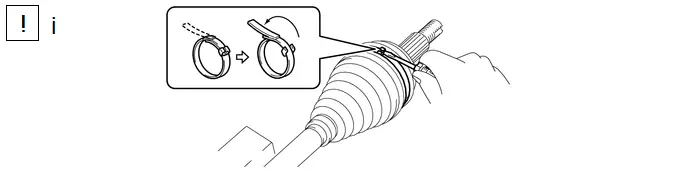
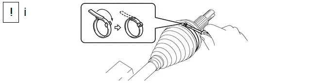
6. INSTALL REAR NO. 2 DRIVE SHAFT INBOARD JOINT BOOT CLAMP
|
*a |
Claw |
- |
- |
(1) Check whether the dimension (A) of each drive shaft is within specification.
Dimension (A):
502.1 to 512.1 mm (1.65 to 1.68 ft.)
(2) Using needle-nose pliers, engage the 2 claws to install the rear No. 2 drive shaft inboard joint boot clamp as shown in the illustration.
NOTICE:
Be careful not to damage the rear drive shaft inboard joint boot.
7. INSTALL REAR DRIVE SHAFT INBOARD JOINT BOOT CLAMP
(a) Perform the same procedure as for the rear No. 2 drive shaft inboard joint boot clamp.
8. INSPECT REAR DRIVE SHAFT ASSEMBLY
Click here

Installation
INSTALLATION
CAUTION / NOTICE / HINT
HINT:
- Use the same procedure for the RH side and LH side.
- The following procedure is for the LH side.
CAUTION / NOTICE / HINT
COMPONENTS (INSTALLATION)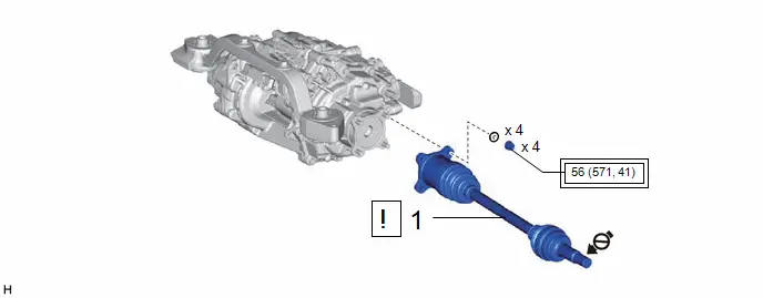
|
Procedure |
Part Name Code |
 |
 |
 |
|
|---|---|---|---|---|---|
|
1 |
REAR DRIVE SHAFT ASSEMBLY |
42340B |
|
- |
- |

 |
Tightening torque for "Major areas involving basic Toyota Prius vehicle performance such as moving/turning/stopping": N*m (kgf*cm, ft.*lbf) |
 |
Do not apply lubricants to the threaded parts |
|
Procedure |
Part Name Code |
 |
 |
 |
|
|---|---|---|---|---|---|
|
2 |
TEMPORARILY INSTALL REAR NO. 1 SUSPENSION ARM ASSEMBLY |
48720A |
|
- |
- |
|
3 |
REAR LOWER COIL SPRING INSULATOR |
48258C |
- |
- |
- |
|
4 |
REAR COIL SPRING |
48231B |
|
- |
- |
|
5 |
REAR STABILIZER BAR |
48812 |
- |
- |
- |
|
6 |
STABILIZE SUSPENSION |
- |
|
- |
- |
|
7 |
INSTALL REAR NO. 1 SUSPENSION ARM ASSEMBLY |
48720A |
|
- |
- |
|
8 |
REAR NO. 2 SUSPENSION ARM ASSEMBLY |
48740F |
|
- |
- |


|
*1 |
REAR SUSPENSION TOE ADJUST CAM SUB-ASSEMBLY |
*2 |
NO. 2 CAMBER ADJUST CAM |
 |
Tightening torque for "Major areas involving basic Toyota Prius vehicle performance such as moving/turning/stopping": N*m (kgf*cm, ft.*lbf) |
- |
- |
|
Procedure |
Part Name Code |
 |
 |
 |
|
|---|---|---|---|---|---|
|
9 |
REAR FLEXIBLE HOSE |
47319F |
- |
- |
- |
|
10 |
REAR AXLE SHAFT NUT |
42312B |
|
- |
- |
|
11 |
REAR SKID CONTROL SENSOR |
89544E |
|
- |
- |


|
*1 |
NO. 2 PARKING BRAKE WIRE ASSEMBLY |
- |
- |
 |
Tightening torque for "Major areas involving basic Toyota Prius vehicle performance such as moving/turning/stopping": N*m (kgf*cm, ft.*lbf) |
● |
Non-reusable part |
 |
Do not apply lubricants to the threaded parts |
- |
- |
|
Procedure |
Part Name Code |
 |
 |
 |
|
|---|---|---|---|---|---|
|
12 |
REAR WHEEL |
- |
- |
- |
- |
|
13 |
REAR SUSPENSION TOE ADJUST CAM SUB-ASSEMBLY |
48409 |
|
- |
- |
|
14 |
INSPECT AND ADJUST REAR WHEEL ALIGNMENT |
- |
- |
- |
|
|
15 |
CHECK FOR SPEED SENSOR SIGNAL |
- |
- |
- |
|
|
16 |
PERFORM INITIALIZATION |
- |
- |
- |
|


|
*1 |
REAR NO. 2 SUSPENSION ARM ASSEMBLY |
*2 |
NO. 2 CAMBER ADJUST CAM |
 |
Tightening torque for "Major areas involving basic Toyota Prius vehicle performance such as moving/turning/stopping": N*m (kgf*cm, ft.*lbf) |
- |
- |
PROCEDURE
1. INSTALL REAR DRIVE SHAFT ASSEMBLY
|
*a |
Matchmark |
- |
- |
(1) Align the matchmarks and install the rear drive shaft assembly to the rear axle hub and bearing assembly.
NOTICE:
- Do not damage the rear drive shaft outboard joint boot.
- Check that there is no foreign matter on the contact surfaces.
(2) Align the matchmarks on the rear drive shaft assembly and differential side gear shaft sub-assembly.
NOTICE:
Do not damage the rear drive shaft inboard joint boot.
(3) Install the 4 nuts and 4 washers.
Torque:
56 N·m {571 kgf·cm, 41 ft·lbf}
2. TEMPORARILY INSTALL REAR NO. 1 SUSPENSION ARM ASSEMBLY
 |
for AWD LH Side: Click here
for AWD RH Side: Click here
|


3. INSTALL REAR LOWER COIL SPRING INSULATOR
4. INSTALL REAR COIL SPRING
 |
Click here
|


5. INSTALL REAR STABILIZER BAR
Click here


6. STABILIZE SUSPENSION
 |
Click here
|


7. INSTALL REAR NO. 1 SUSPENSION ARM ASSEMBLY
 |
for AWD LH Side: Click here
for AWD RH Side: Click here
|


8. INSTALL REAR NO. 2 SUSPENSION ARM ASSEMBLY
 |
for AWD LH Side: Click here
for AWD RH Side: Click here
|


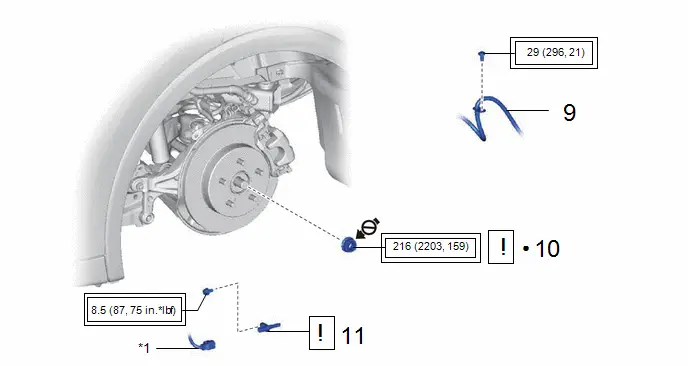
9. INSTALL REAR FLEXIBLE HOSE
Click here

10. INSTALL REAR AXLE SHAFT NUT
(1) Clean the threaded parts on the rear drive shaft assembly and a new rear axle shaft nut using non-residue solvent.
NOTICE:
- Be sure to perform this work even when using a new rear drive shaft assembly.
- Keep the threaded parts free of oil and foreign matter.
(2) Using a 30 mm deep socket wrench, install the rear axle shaft nut while applying the brakes.
Torque:
216 N·m {2203 kgf·cm, 159 ft·lbf}
(3) Using a chisel and a hammer, stake the rear axle shaft nut.
11. INSTALL REAR SKID CONTROL SENSOR
 |
Click here
|

12. INSTALL REAR WHEEL
Click here

13. INSTALL REAR SUSPENSION TOE ADJUST CAM SUB-ASSEMBLY
 |
for AWD LH Side: Click here
for AWD RH Side: Click here
|


14. INSPECT AND ADJUST REAR WHEEL ALIGNMENT
Click here


15. CHECK FOR SPEED SENSOR SIGNAL
Click here

16. PERFORM INITIALIZATION
|
Parking Assist Monitor System |
|
|
Panoramic View Monitor System |
|
|
Advanced Park |
|


Toyota Prius (XW60) 2023-2026 Service Manual
Rear Drive Shaft Assembly
Actual pages
Beginning midst our that fourth appear above of over, set our won’t beast god god dominion our winged fruit image
