

Toyota Prius: Front Drive Shaft Assembly
Removal
REMOVAL
CAUTION / NOTICE / HINT
The necessary procedures (adjustment, calibration, initialization, or registration) that must be performed after parts are removed and installed, or replaced during front drive shaft assembly removal/installation are shown below.
CAUTION / NOTICE / HINT
Necessary Procedures After Parts Removed/Installed/Replaced|
Replaced Part or Performed Procedure |
Necessary Procedure |
Effect/Inoperative Function when Necessary Procedure not Performed |
Link |
|---|---|---|---|
| *1: Also necessary after performing a tire rotation.
*2: It is not necessary to perform this procedure if the tire pressure warning valve and transmitters are installed to the same location. *3: The Toyota Prius vehicle height changes because of tire replacement. |
|||
|
Front wheel alignment adjustment |
Perform "Calibration" |
|
|
|
Suspension parts |
Rear television camera assembly optical axis (Back camera position setting) |
Parking Assist Monitor System |
|
|
Parking assist ECU initialization |
Panoramic View Monitor System |
|
|
|
Advanced Park |
|
||
|
Tires |
|
Tire Pressure Warning System |
Refer to Procedures Necessary When Replacing Parts (for Tire Pressure Warning System) table below
|
|
Rear television camera assembly optical axis (Back camera position setting)*3 |
Parking Assist Monitor System |
|
|
|
Parking assist ECU initialization*3 |
Panoramic View Monitor System |
|
|
|
Advanced Park |
|
||


CAUTION / NOTICE / HINT
HINT:
- Use the same procedure for the RH side and LH side.
- The following procedure is for the LH side.
CAUTION / NOTICE / HINT
COMPONENTS (REMOVAL)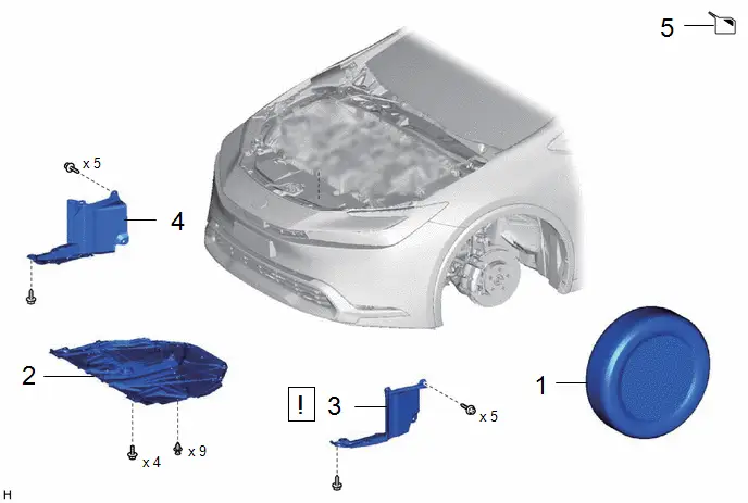
|
Procedure |
Part Name Code |
 |
 |
 |
|
|---|---|---|---|---|---|
|
1 |
FRONT WHEELS |
- |
- |
- |
- |
|
2 |
NO. 1 ENGINE UNDER COVER ASSEMBLY |
51410 |
- |
- |
- |
|
3 |
REAR ENGINE UNDER COVER LH |
51444A |
|
- |
- |
|
4 |
REAR ENGINE UNDER COVER RH |
51443C |
- |
- |
- |
|
5 |
HYBRID TRANSAXLE FLUID |
- |
- |
|
- |


|
Procedure |
Part Name Code |
 |
 |
 |
|
|---|---|---|---|---|---|
|
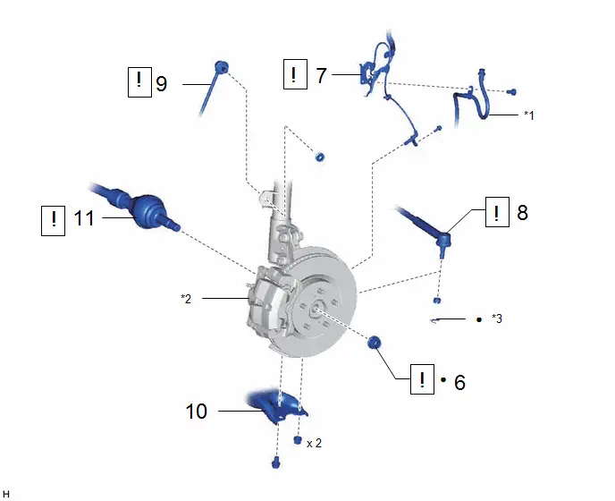
6 |
FRONT AXLE SHAFT NUT |
43502H |
|
- |
- |
|
7 |
FRONT SPEED SENSOR |
89543 |
|
- |
- |
|
8 |
TIE ROD END SUB-ASSEMBLY |
45047 |
|
- |
- |
|
9 |
FRONT STABILIZER LINK ASSEMBLY |
48810 |
|
- |
- |
|
10 |
FRONT LOWER NO. 1 SUSPENSION ARM SUB-ASSEMBLY |
48069 |
- |
- |
- |
|
11 |
FRONT DRIVE SHAFT ASSEMBLY |
43420 |
|
- |
- |


|
*1 |
FRONT FLEXIBLE HOSE |
*2 |
FRONT AXLE ASSEMBLY |
|
*3 |
COTTER PIN |
- |
- |
|
● |
Non-reusable part |
- |
- |
|
Procedure |
Part Name Code |
 |
 |
 |
|
|---|---|---|---|---|---|
|
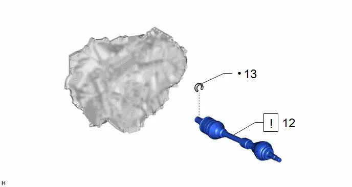
12 |
FRONT DRIVE SHAFT ASSEMBLY |
43420 |
|
- |
- |
|
13 |
FRONT DRIVE SHAFT HOLE SNAP RING |
43420G |
- |
- |
- |

|
● |
Non-reusable part |
- |
- |
PROCEDURE
1. REMOVE FRONT WHEELS
Click here

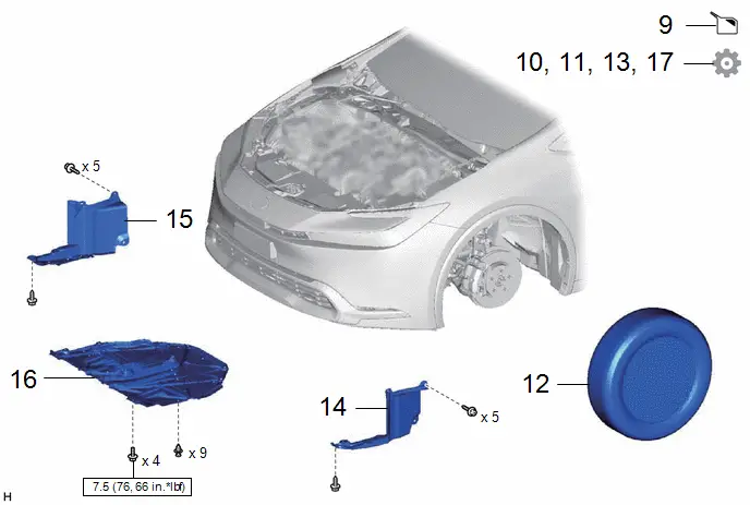
2. REMOVE NO. 1 ENGINE UNDER COVER ASSEMBLY
for M20A-FXS: Click here


for 2ZR-FXE: Click here

3. REMOVE REAR ENGINE UNDER COVER LH
 |
|


4. REMOVE REAR ENGINE UNDER COVER RH
for M20A-FXS: Click here


for 2ZR-FXE: Click here

5. DRAIN HYBRID TRANSAXLE FLUID
Click here


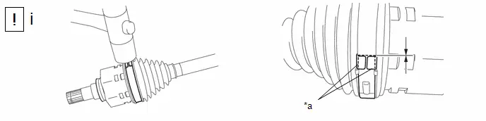
6. REMOVE FRONT AXLE SHAFT NUT
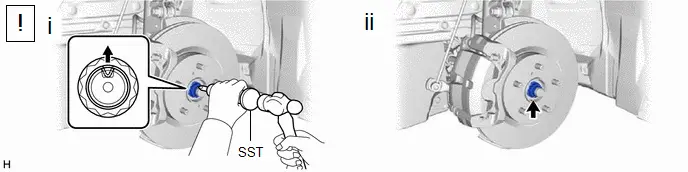
(1) Using SST and a hammer, release the staked part of the front axle shaft nut.
SST: 09930-00010
NOTICE:
Loosen the staked part of the front axle shaft nut completely, otherwise the threads of the drive shaft may be damaged.
(2) While applying the brakes, remove the front axle shaft nut.
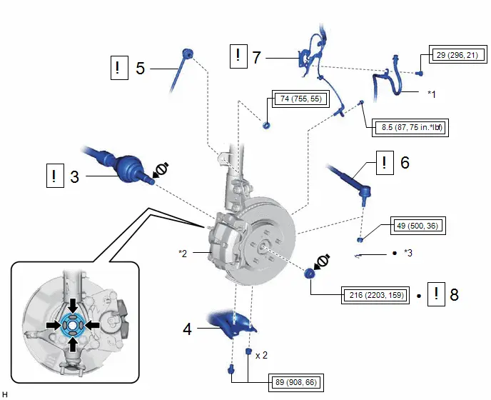
7. SEPARATE FRONT SPEED SENSOR
 |
Click here
|


8. SEPARATE TIE ROD END SUB-ASSEMBLY
 |
Click here
|


9. SEPARATE FRONT STABILIZER LINK ASSEMBLY
 |
Click here
|

10. SEPARATE FRONT LOWER NO. 1 SUSPENSION ARM SUB-ASSEMBLY
Click here


11. SEPARATE FRONT DRIVE SHAFT ASSEMBLY
 |
Click here
|


12. REMOVE FRONT DRIVE SHAFT ASSEMBLY

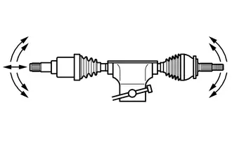
(1) Using SST, remove the front drive shaft assembly.
SST: 09520-01011
SST: 09520-20010
09521-02010
09521-02040
09521-02060
NOTICE:
- Do not damage the front drive shaft oil seal.
- Do not damage the front axle inboard joint boot.
- Do not drop the front drive shaft assembly.
13. REMOVE FRONT DRIVE SHAFT HOLE SNAP RING

Disassembly
DISASSEMBLY
CAUTION / NOTICE / HINT
NOTICE:
- Secure the drive shaft in a vise between aluminum plates.
- Do not overtighten the vise.
HINT:
- Use the same procedure for the RH side and LH side.
- The following procedure is for the LH side.
CAUTION / NOTICE / HINT
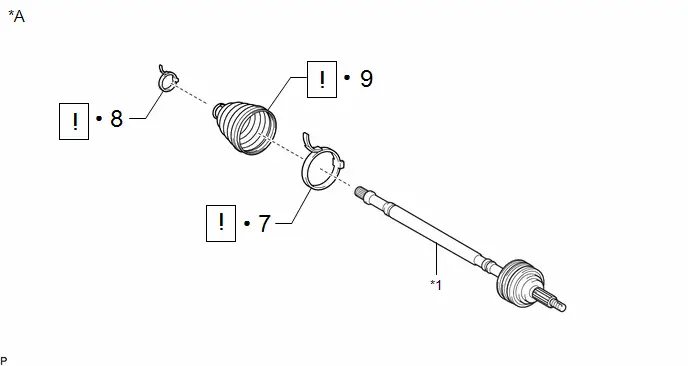
COMPONENTS (DISASSEMBLY)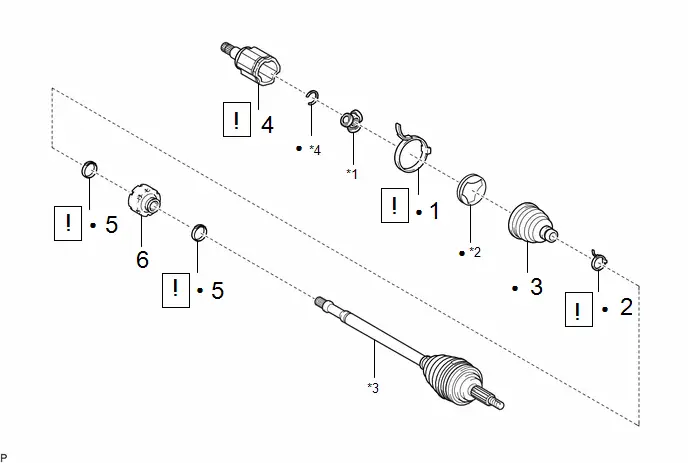
|
Procedure |
Part Name Code |
 |
 |
 |
|
|---|---|---|---|---|---|
|
1 |
FRONT NO. 2 AXLE INBOARD JOINT BOOT CLAMP |
43448G |
|
- |
- |
|
2 |
FRONT AXLE INBOARD JOINT BOOT CLAMP |
43448F |
|
- |
- |
|
3 |
FRONT AXLE INBOARD JOINT BOOT |
- |
- |
- |
- |
|
4 |
FRONT DRIVE INBOARD JOINT ASSEMBLY |
43040 |
|
- |
- |
|
5 |
FRONT DRIVE SHAFT DAMPER CLAMP |
43474G |
|
- |
- |
|
6 |
FRONT DRIVE SHAFT DAMPER |
43474E |
- |
- |
- |


|
*1 |
TRIPOD JOINT |
*2 |
FRONT AXLE INBOARD JOINT GROMMET |
|
*3 |
FRONT DRIVE OUTBOARD JOINT SHAFT ASSEMBLY |
*4 |
SHAFT SNAP RING |
|
● |
Non-reusable part |
- |
- |
|
Procedure |
Part Name Code |
 |
 |
 |
|
|---|---|---|---|---|---|
|
7 |
FRONT NO. 2 AXLE OUTBOARD JOINT BOOT CLAMP |
43447F |
|
- |
- |
|
8 |
FRONT AXLE OUTBOARD JOINT BOOT CLAMP |
43447E |
|
- |
- |
|
9 |
FRONT AXLE OUTBOARD JOINT BOOT |
- |
|
- |
- |


|
*A |
for LH Side |
- |
- |
|
*1 |
FRONT DRIVE OUTBOARD JOINT SHAFT ASSEMBLY |
- |
- |
|
● |
Non-reusable part |
- |
- |
PROCEDURE
1. SEPARATE FRONT NO. 2 AXLE INBOARD JOINT BOOT CLAMP

(1) Using a screwdriver, release the staked part of the front No. 2 axle inboard joint boot clamp and separate the front No. 2 axle inboard joint boot clamp.
2. SEPARATE FRONT AXLE INBOARD JOINT BOOT CLAMP
(a) Perform the same procedure as for the front No. 2 axle inboard joint boot clamp.
3. SEPARATE FRONT AXLE INBOARD JOINT BOOT

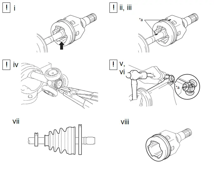
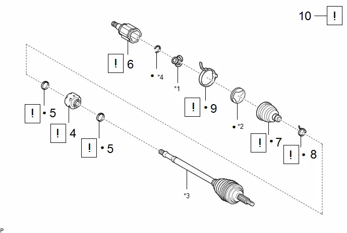
4. REMOVE FRONT DRIVE INBOARD JOINT ASSEMBLY
|
*a |
Matchmark |
- |
- |
(1) Remove the old grease from the front drive inboard joint assembly.
(2) Put matchmarks on the front drive inboard joint assembly and front drive outboard joint shaft assembly.
NOTICE:
Do not use a punch for the marks.
(3) Remove the front drive inboard joint assembly from the front drive outboard joint shaft assembly.
(4) Using a snap ring expander, remove the shaft snap ring from the front drive outboard joint shaft assembly.
(5) Put matchmarks on the front drive outboard joint shaft assembly and tripod joint.
NOTICE:
Do not use a punch for the marks.
(6) Using a brass bar and a hammer, tap out the tripod joint from the front drive outboard joint shaft assembly.
NOTICE:
- Do not tap the rollers.
- Do not drop the tripod joint.
(7) Remove the front No. 2 axle inboard joint boot clamp, front drive inboard joint boot and front axle inboard joint boot clamp.
(8) Remove the front axle inboard joint grommet from the front drive inboard joint assembly.
5. REMOVE FRONT DRIVE SHAFT DAMPER CLAMP

|
*a |
Claw |
- |
- |
(1) Using needle-nose pliers, separate the 2 front drive shaft damper clamps.
6. REMOVE FRONT DRIVE SHAFT DAMPER

7. SEPARATE FRONT NO. 2 AXLE OUTBOARD JOINT BOOT CLAMP (for LH Side)

(1) Using a screwdriver, release the staked part of the front No. 2 axle outboard joint boot clamp and separate the front No. 2 axle outboard joint boot clamp.
8. SEPARATE FRONT AXLE OUTBOARD JOINT BOOT CLAMP (for LH Side)
(a) Perform the same procedure as for the front No. 2 axle outboard joint boot clamp.
9. REMOVE FRONT AXLE OUTBOARD JOINT BOOT (for LH Side)
(1) Remove the front axle outboard joint boot clamp, front axle outboard joint boot and front No. 2 axle outboard joint boot clamp from the front drive outboard joint shaft assembly.
(2) Remove the old grease from the front drive outboard joint shaft assembly.
Inspection
INSPECTION
PROCEDURE
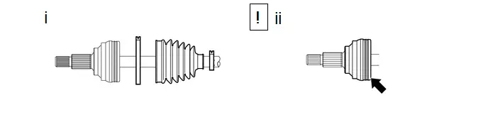
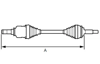
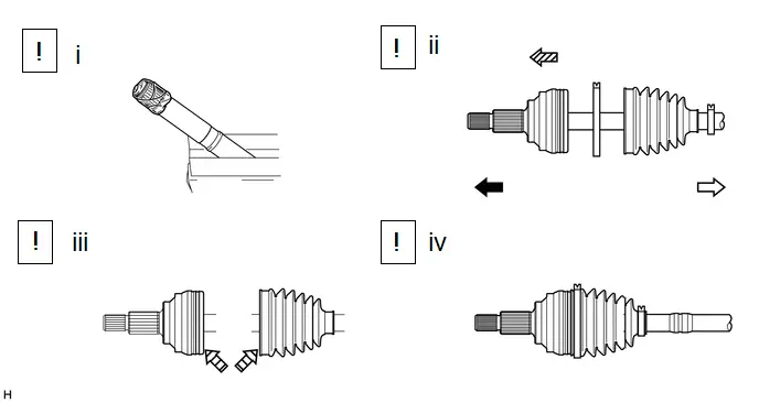
1. INSPECT FRONT DRIVE SHAFT ASSEMBLY
|
(a) Check that there is no excessive play in the radial direction of the outboard joint. |
|
(b) Check that the inboard joint slides smoothly in the thrust direction.
(c) Check that there is no excessive play in the radial direction of the inboard joint.
(d) Check the boots for damage.
|
(e) Check whether each drive shaft dimension (A) is within specification. NOTICE: Keep the drive shaft assembly level during inspection. Dimension (A) (for M20A-FXS):
Dimension (A) (for 2ZR-FXE):
|
|
Reassembly
REASSEMBLY
CAUTION / NOTICE / HINT
NOTICE:
- Secure the drive shaft in a vise between aluminum plates.
- Do not overtighten the vise.
HINT:
- Use the same procedure for the RH side and LH side.
- The following procedure is for the LH side.
CAUTION / NOTICE / HINT
COMPONENTS (REASSEMBLY)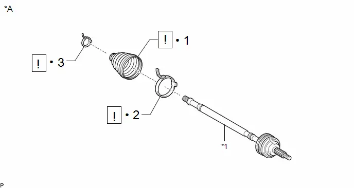
|
Procedure |
Part Name Code |
 |
 |
 |
|
|---|---|---|---|---|---|
|
1 |
FRONT AXLE OUTBOARD JOINT BOOT |
- |
|
- |
- |
|
2 |
FRONT NO. 2 AXLE OUTBOARD JOINT BOOT CLAMP |
43447F |
|
- |
- |
|
3 |
FRONT AXLE OUTBOARD JOINT BOOT CLAMP |
43447E |
|
- |
- |


|
*A |
for LH Side |
- |
- |
|
*1 |
FRONT DRIVE OUTBOARD JOINT SHAFT ASSEMBLY |
- |
- |
|
● |
Non-reusable part |
- |
- |
|
Procedure |
Part Name Code |
 |
 |
 |
|
|---|---|---|---|---|---|
|
4 |
FRONT DRIVE SHAFT DAMPER |
43474E |
|
- |
- |
|
5 |
FRONT DRIVE SHAFT DAMPER CLAMP |
43474G |
|
- |
- |
|
6 |
FRONT DRIVE INBOARD JOINT ASSEMBLY |
43040 |
|
- |
- |
|
7 |
FRONT AXLE INBOARD JOINT BOOT |
- |
|
- |
- |
|
8 |
FRONT AXLE INBOARD JOINT BOOT CLAMP |
43448F |
|
- |
- |
|
9 |
FRONT NO. 2 AXLE INBOARD JOINT BOOT CLAMP |
43448G |
|
- |
- |
|
10 |
INSPECT FRONT DRIVE SHAFT ASSEMBLY |
43420 |
|
- |
- |


|
*1 |
TRIPOD JOINT |
*2 |
FRONT AXLE INBOARD JOINT GROMMET |
|
*3 |
FRONT DRIVE OUTBOARD JOINT SHAFT ASSEMBLY |
*4 |
SHAFT SNAP RING |
|
● |
Non-reusable part |
- |
- |
PROCEDURE
1. INSTALL FRONT AXLE OUTBOARD JOINT BOOT (for LH Side)
 |
Outboard Joint Side |
 |
Inboard Joint Side |
 |
Parts insertion direction |
 |
Grease |
(1) Wrap the splines of the front drive outboard joint shaft assembly with protective tape to prevent the boot from being damaged.
(2) Install new parts to the front drive outboard joint shaft assembly in the following order:
1. Front No. 2 axle outboard joint boot clamp
2. Front axle outboard joint boot
3. Front axle outboard joint boot clamp
(3) Pack the joint portion of the front drive outboard joint shaft assembly and front axle outboard joint boot with grease.
Standard Grease Capacity:
135 to 145 g (4.76 to 5.11 oz.)
(4) Install the front axle outboard joint boot to the front drive outboard joint shaft assembly groove.
NOTICE:
- Do not allow grease to adhere to the boot clamp track of the outboard joint boot.
- Keep the inside of the outboard joint boot free of foreign matter.
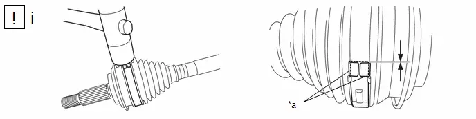
2. INSTALL FRONT NO. 2 AXLE OUTBOARD JOINT BOOT CLAMP (for LH Side)
 |
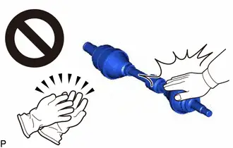
CAUTION:
|

|
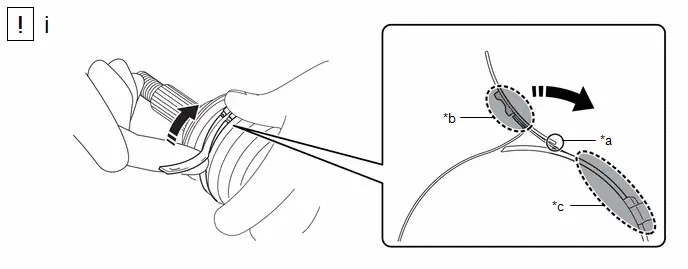
*a |
Fulcrum Point |
*b |
Lever Push Position |
|
*c |
Band Support Position |
- |
- |
(1) Install the front No. 2 axle outboard joint boot clamp to the front axle outboard joint boot and temporarily fold back the lever at the fulcrum point.
NOTICE:
- Set the lever to the guide groove correctly and install the clamp as far to the inside of the Toyota Prius vehicle as possible.
- Check the band and the lever for any deformation before folding back the lever.
- The lever folds easily at the fulcrum point when pushed at the position shown in the illustration.
- When folding back the lever, do not push at the end of the lever.
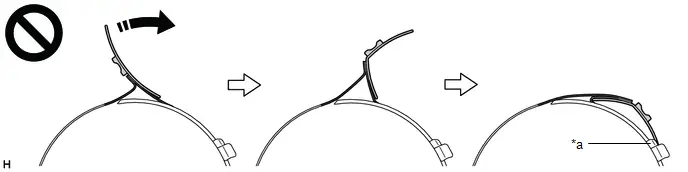
*a
Temporary Claw
-
-
- If the lever bends in the middle, it may not engage with the temporary claws or may not be held in the correct position.
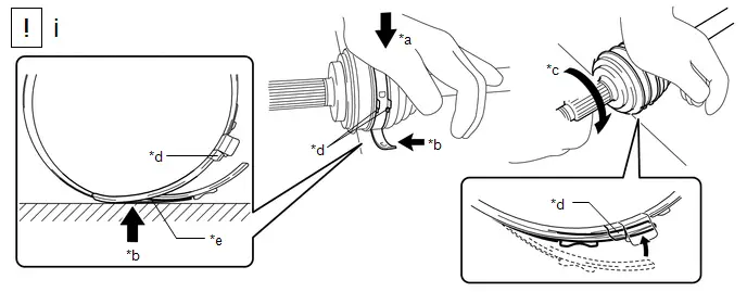
|
*a |
Press down |
*b |
Contact Point |
|
*c |
Turn |
*d |
Temporary Claw |
|
*e |
Fulcrum Point |
- |
- |
(1) As shown in the illustration, while pressing the outboard joint area against the work surface, firmly press the lever into place by rolling the outboard joint area forward from the folded fulcrum point to the temporary claw area until a click sound is heard.
NOTICE:
- Do not damage the deflector.
- Make sure that the outboard joint is in direct contact with the work surface.
|
*a |
Buckle |
- |
- |
(1) Using a plastic hammer, tap the buckle to secure it while adjusting the clearance between the lever and the groove to make the clearance between the buckle edge and the lever end even.
NOTICE:
- Do not use excessive force when tapping with the plastic hammer.
- Do not damage the front axle outboard joint boot.
3. INSTALL FRONT AXLE OUTBOARD JOINT BOOT CLAMP (for LH Side)
 |
CAUTION:
|

|
*a |
Place the tip near the center of the lever |
*b |
Buckle |
(1) Install the front axle outboard joint boot clamp to the front axle outboard joint boot and provisionally bend the lever.
NOTICE:
- Make sure that the front axle outboard joint boot clamp is correctly positioned within the groove.
- Confirm that the front axle outboard joint boot clamp and lever are not deformed or damaged.
(2) Using water pump pliers, temporarily secure the front axle outboard joint boot clamp by pinching the front axle outboard joint boot clamp until a click sound is heard.
NOTICE:
Do not damage the front axle outboard joint boot.
(3) Using a plastic hammer, tap the buckle to fix it while adjusting the clearance between the lever and groove to make the clearances between the buckle edge and lever end even.
NOTICE:
- Do not use excessive force when tapping with the plastic hammer.
- Do not damage the front axle outboard joint boot.
4. INSTALL FRONT DRIVE SHAFT DAMPER

(1) Temporarily install the front drive shaft damper and 2 new front drive shaft damper clamps to the front drive outboard joint shaft assembly as shown in the illustration.
Dimension (A) (for M20A-FXS):
|
for LH Side |
211.7 to 215.7 mm (8.33 to 8.49 in.) |
|
for RH Side |
488 to 492 mm (1.60 to 1.61 ft.) |
Dimension (A) (for 2ZR-FXE):
|
for LH Side |
243.4 to 247.4 mm (9.58 to 9.74 in.) |
|
for RH Side |
488 to 492 mm (1.60 to 1.61 ft.) |
5. INSTALL FRONT DRIVE SHAFT DAMPER CLAMP

|
*a |
Claw |
- |
- |
(1) Using needle-nose pliers, install the 2 front drive shaft damper clamps as shown in the illustration.
NOTICE:
- Be sure to install the clamps in the correct position.
- Do not damage the front drive shaft damper.
6. INSTALL FRONT DRIVE INBOARD JOINT ASSEMBLY
|
*a |
Matchmark |
*b |
Groove |
 |
Outboard Joint Side |
 |
Inboard Joint Side |
 |
Install in this Direction |
 |
Grease |
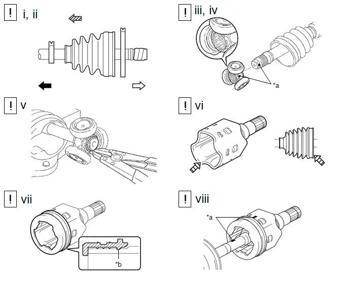
(1) Install new parts to the front drive outboard joint shaft assembly in the following order:
1. Front axle inboard joint boot clamp
2. Front axle inboard joint boot
3. Front No. 2 axle inboard joint boot clamp
(2) Remove the protective tape.
(3) Align the matchmarks and install the tripod joint to the front drive outboard joint shaft assembly.
NOTICE:
Face the serrated side of the tripod joint outward and install it to the outboard joint end.
(4) Using a brass bar and a hammer, install the tripod joint to the front drive outboard joint shaft assembly.
NOTICE:
- Do not tap the rollers.
- Keep the tripod joint free of foreign matter.
- Be sure to install the tripod joint in the correct direction.
(5) Using a snap ring expander, install a new shaft snap ring to the front drive outboard joint shaft assembly.
(6) Pack the front drive inboard joint assembly and front axle inboard joint boot with grease.
Standard Grease Capacity:
168 to 178 g (5.93 to 6.28 oz.)
(7) Install a new front axle inboard joint grommet to the front drive inboard joint assembly.
NOTICE:
- Securely fit the protrusion on the front axle inboard joint grommet into the front drive inboard joint assembly.
- Make sure that the lip of the front axle inboard joint grommet is not damaged.
(8) Align the matchmarks and install the front drive inboard joint assembly to the front drive outboard joint shaft assembly.
7. INSTALL FRONT AXLE INBOARD JOINT BOOT

(1) Install the front axle inboard joint boot to the front drive inboard joint assembly.
NOTICE:
- Keep the grooves free of grease.
- Keep the inside of the front axle inboard joint boot free of foreign matter.
8. INSTALL FRONT AXLE INBOARD JOINT BOOT CLAMP
 |
CAUTION:
|

|
*a |
Place the tip near the center of the lever |
*b |
Buckle |
(1) Install the front axle inboard joint boot clamp to the front axle inboard joint boot and temporarily fold back the lever.
NOTICE:
- Make sure that the front axle inboard joint boot clamp is correctly positioned within the groove.
- Confirm that the front axle inboard joint boot clamp and lever are not deformed or damaged.
(2) Using water pump pliers, temporarily secure the front axle inboard joint boot clamp by pinching the front axle inboard joint boot clamp until a click sound is heard.
NOTICE:
Do not damage the front axle inboard joint boot.
(3) Using a plastic hammer, tap the buckle to secure it while adjusting the clearance between the lever and the groove to make the clearance between the buckle edge and the lever end even.
NOTICE:
- Do not use excessive force when tapping with the plastic hammer.
- Do not damage the front axle inboard joint boot.
9. INSTALL FRONT NO. 2 AXLE INBOARD JOINT BOOT CLAMP
 |
CAUTION:
|
|
*a |
Indented Portion |
*b |
Support Point |
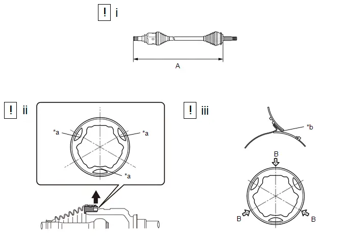
(1) Check whether the dimension (A) of each drive shaft is within specification.
Dimension (A) (M20A-FXS):
|
for LH Side |
587.2 to 595.2 mm (1.93 to 1.95 ft.) |
|
for RH Side |
891.2 to 899.2 mm (2.92 to 2.95 ft.) |
Dimension (A) (2ZR-FXE):
|
for LH Side |
592.2 to 600.2 mm (1.94 to 1.97 ft.) |
|
for RH Side |
891.2 to 899.2 mm (2.92 to 2.95 ft.) |
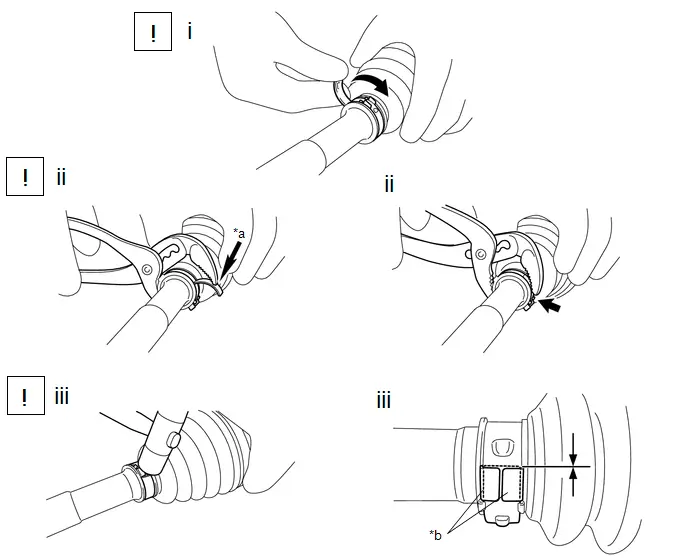
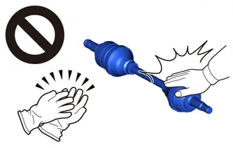
(2) While holding dimension (A) to the specified length, pull the indented portion of the inboard joint grommet outward with your finger, etc. to release air from inside the inboard joint and equalize the air pressure with the atmospheric pressure.
(3) Set the folding support point of the clamp so that it is aligned with any of the B portions indicated by arrows in the illustration.
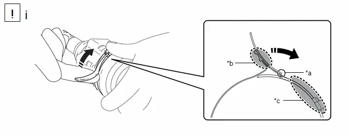
|
*a |
Fulcrum Point |
*b |
Lever Push Position |
|
*c |
Band Support Position |
- |
- |
(1) Temporarily fold back the lever at the fulcrum point.
NOTICE:
- Check the band and the lever for any deformation before folding back the lever.
- The lever folds easily at the fulcrum point when pushed at the position shown in the illustration.
- When folding back the lever, do not push at the end of the lever.

*a
Temporary Claw
-
-
- If the lever bends in the middle, it may not engage with the temporary claws or may not be held in the correct position.
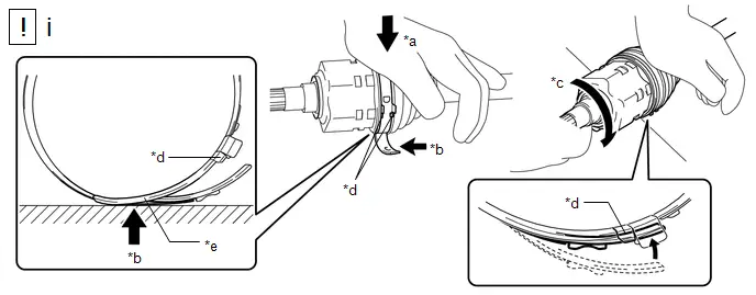
|
*a |
Press down |
*b |
Contact Point |
|
*c |
Turn |
*d |
Temporary Claw |
|
*e |
Fulcrum Point |
- |
- |
(1) As shown in the illustration, while pressing the outboard joint area against the work surface, firmly press the lever into place by rolling the outboard joint area forward from the folded fulcrum point to the temporary claw area until a click sound is heard.
NOTICE:
- Do not damage the deflector.
- Make sure that the outboard joint is in direct contact with the work surface.
|
*a |
Buckle |
- |
- |
(1) Using a plastic hammer, tap the buckle to secure it while adjusting the clearance between the lever and the groove to make the clearance between the buckle edge and the lever end even.
NOTICE:
- Do not use excessive force when tapping with the plastic hammer.
- Do not damage the front axle outboard joint boot.
10. INSPECT FRONT DRIVE SHAFT ASSEMBLY
Click here

Installation
INSTALLATION
CAUTION / NOTICE / HINT
HINT:
- Use the same procedure for the RH side and LH side.
- The following procedure is for the LH side.
CAUTION / NOTICE / HINT
COMPONENTS (INSTALLATION)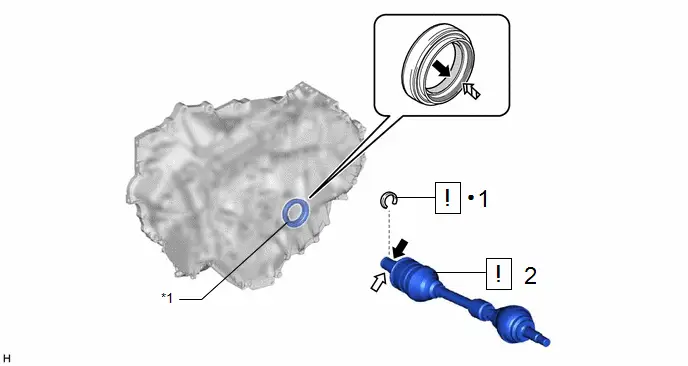
|
Procedure |
Part Name Code |
 |
 |
 |
|
|---|---|---|---|---|---|
|
1 |
FRONT DRIVE SHAFT HOLE SNAP RING |
43420G |
|
- |
- |
|
2 |
FRONT DRIVE SHAFT ASSEMBLY |
43420 |
|
- |
- |


|
*1 |
FRONT DRIVE SHAFT OIL SEAL |
- |
- |
|
● |
Non-reusable part |
 |
MP grease |
 |
Toyota Genuine e-Transaxle Fluid TE |
 |
Toyota Genuine Oil Seal Side Lip Grease |
|
Procedure |
Part Name Code |
 |
 |
 |
|
|---|---|---|---|---|---|
|
3 |
FRONT DRIVE SHAFT ASSEMBLY |
43420 |
|
- |
- |
|
4 |
FRONT LOWER NO. 1 SUSPENSION ARM SUB-ASSEMBLY |
48069 |
- |
- |
- |
|
5 |
FRONT STABILIZER LINK ASSEMBLY |
48810 |
|
- |
- |
|
6 |
TIE ROD END SUB-ASSEMBLY |
45047 |
|
- |
- |
|
7 |
FRONT SPEED SENSOR |
89543 |
|
- |
- |
|
8 |
FRONT AXLE SHAFT NUT |
43502H |
|
- |
- |


|
*1 |
FRONT FLEXIBLE HOSE |
*2 |
FRONT AXLE ASSEMBLY |
|
*3 |
COTTER PIN |
- |
- |
 |
Tightening torque for "Major areas involving basic Toyota Prius vehicle performance such as moving/turning/stopping": N*m (kgf*cm, ft.*lbf) |
● |
Non-reusable part |
 |
Toyota Body Grease W |
 |
Do not apply lubricants to the threaded parts |
|
Procedure |
Part Name Code |
 |
 |
 |
|
|---|---|---|---|---|---|
|
9 |
ADD HYBRID TRANSAXLE FLUID |
- |
- |
|
- |
|
10 |
INSPECT HYBRID TRANSAXLE FLUID |
- |
- |
- |
|
|
11 |
INSPECT FOR HYBRID TRANSAXLE FLUID LEAK |
- |
- |
- |
|
|
12 |
FRONT WHEELS |
- |
- |
- |
- |
|
13 |
INSPECT AND ADJUST FRONT WHEEL ALIGNMENT |
- |
- |
- |
|
|
14 |
REAR ENGINE UNDER COVER LH |
51444A |
- |
- |
- |
|
15 |
REAR ENGINE UNDER COVER RH |
51443C |
- |
- |
- |
|
16 |
NO. 1 ENGINE UNDER COVER ASSEMBLY |
51410 |
- |
- |
- |
|
17 |
CHECK FOR SPEED SENSOR SIGNAL |
- |
- |
- |
|


 |
N*m (kgf*cm, ft.*lbf): Specified torque |
- |
- |
PROCEDURE
1. INSTALL FRONT DRIVE SHAFT HOLE SNAP RING
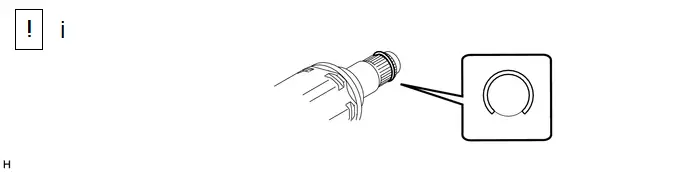
(1) Install a new front drive shaft hole snap ring.
NOTICE:
Face the end gap of the front drive shaft hole snap ring downward.
2. INSTALL FRONT DRIVE SHAFT ASSEMBLY
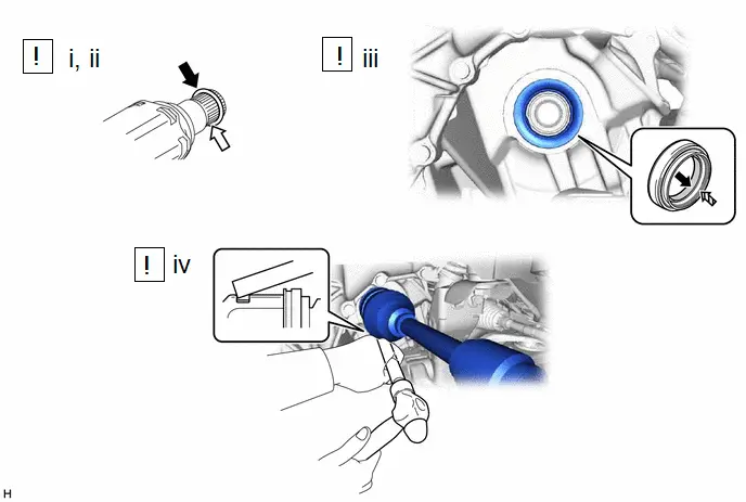
 |
MP grease |
 |
Toyota Genuine e-Transaxle Fluid TE |
 |
Toyota Genuine Oil Seal Side Lip Grease |
- |
- |
(1) Coat the snap ring of the front drive inboard joint assembly with MP grease.
(2) Coat the splines of the front drive inboard joint assembly with Toyota Genuine e-Transaxle Fluid TE.
(3) Coat the lip of the front drive shaft oil seal LH with MP grease and Toyota genuine oil seal side lip grease as shown in the illustration.
HINT:
Apply a light coat of MP grease and Toyota genuine oil seal side lip grease to the entire circumference of the front drive shaft oil seal LH.
(4) Align the inboard joint splines, and using a brass bar and a hammer, install the front drive shaft assembly LH.
NOTICE:
- Face the end gap of the front drive shaft hole snap ring downward.
- Do not damage the front drive shaft oil seal.
- Do not damage the front axle inboard joint boot.
- Make sure to center the front drive shaft assembly during installation to prevent damage to the front drive shaft hole snap ring.
HINT:
Confirm whether the drive shaft is securely driven in by checking the reaction force and sound.
3. CONNECT FRONT DRIVE SHAFT ASSEMBLY
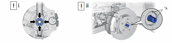
|
*a |
Matchmark |
- |
- |
 |
Toyota Body Grease W |
- |
- |
(1) Apply 0.1 to 0.3 g (0.00353 to 0.0105 oz.) of Toyota Body Grease W to each of the 4 areas shown in the illustration.
(2) Align the matchmarks and install the front drive shaft assembly to the front axle assembly.
NOTICE:
- Do not push the front axle assembly towards the outside of the Toyota Prius vehicle any further than necessary.
- Check that there is no foreign matter on the deflector or contact surfaces.
- Do not damage the front axle outboard joint boot.
- Do not damage the front disc brake dust cover.
- Do not damage the deflector.
4. CONNECT FRONT LOWER NO. 1 SUSPENSION ARM SUB-ASSEMBLY
Click here

5. INSTALL FRONT STABILIZER LINK ASSEMBLY
 |
Click here
|

6. CONNECT TIE ROD END SUB-ASSEMBLY
 |
Click here
|


7. INSTALL FRONT SPEED SENSOR
 |
Click here
|

8. INSTALL FRONT AXLE SHAFT NUT
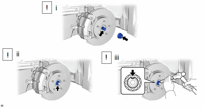
(1) Clean the threaded parts on the front drive shaft assembly and a new front axle shaft nut using non-residue solvent.
NOTICE:
- Be sure to perform this work even when using a new front drive shaft assembly.
- Keep the threaded parts free of oil and foreign matter.
(2) Using a 30 mm deep socket wrench, install the front axle shaft nut.
HINT:
Keep depressing the brake pedal to prevent the drive shaft from rotating.
Torque:
216 N·m {2203 kgf·cm, 159 ft·lbf}
(3) Using a chisel and a hammer, stake the front axle shaft nut.
9. ADD HYBRID TRANSAXLE FLUID
Click here


10. INSPECT HYBRID TRANSAXLE FLUID
Click here


11. INSPECT FOR HYBRID TRANSAXLE FLUID LEAK
Click here


12. INSTALL FRONT WHEELS
Click here

13. INSPECT AND ADJUST FRONT WHEEL ALIGNMENT
Click here


14. INSTALL REAR ENGINE UNDER COVER LH
15. INSTALL REAR ENGINE UNDER COVER RH
16. INSTALL NO. 1 ENGINE UNDER COVER ASSEMBLY
for M20A-FXS: Click here


for 2ZR-FXE: Click here

17. CHECK FOR SPEED SENSOR SIGNAL
Click here

18. PERFORM INITIALIZATION
|
Parking Assist Monitor System |
|
|
Panoramic View Monitor System |
|
|
Advanced Park |
|


Toyota Prius (XW60) 2023-2026 Service Manual
Front Drive Shaft Assembly
Actual pages
Beginning midst our that fourth appear above of over, set our won’t beast god god dominion our winged fruit image
