

Toyota Prius: Rear Bumper
Removal
REMOVAL
CAUTION / NOTICE / HINT
The necessary procedures (adjustment, calibration, initialization or registration) that must be performed after parts are removed and installed, or replaced during rear bumper assembly removal/installation are shown below.
HINT:
-
When the rear bumper is damaged or deformed due to an accident or contact with other objects, etc., or the bumper installation area on the body is repaired, it is necessary to perform ultrasonic sensor detection angle measurement.
-
w/ Parking Support Brake System:
Click here

-
w/ Advanced Park:
Click here

-
w/ Parking Support Brake System:
- If the bumper is damaged, there is a possibility that the installation area of the blind spot monitor sensor may be deformed and the blind spot monitor system may not operate correctly, so visually inspect the blind spot monitor sensor installation area (frame, stud bolt) to make sure it is not dented or bent.
-
If a problem is found during the visual inspection, check the installation condition of the blind spot monitor sensor, and adjust the installation position of the blind spot monitor sensor as necessary.
-
Driving Adjustment:
Click here

-
Target Adjustment (Triangle Target):
Click here

-
Driving Adjustment:
CAUTION / NOTICE / HINT
COMPONENTS (REMOVAL)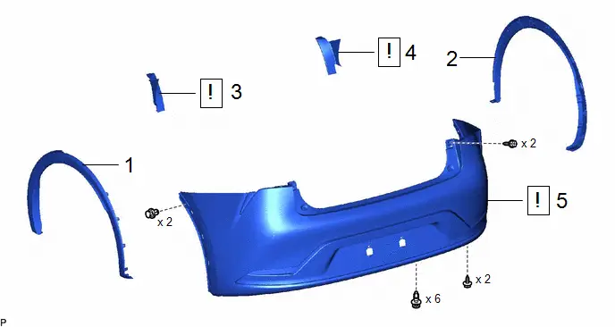
| Procedure | Part Name Code |

|

|

| |
|---|---|---|---|---|---|
| 1 | QUARTER OUTSIDE MOULDING SUB-ASSEMBLY LH | 75606B | - | - | - |
| 2 | QUARTER OUTSIDE MOULDING SUB-ASSEMBLY RH | 75605B | - | - | - |
| 3 | REAR COMBINATION LIGHT COVER LH | 81498 |
| - | - |
| 4 | REAR COMBINATION LIGHT COVER RH | 81497 |
| - | - |
| 5 | REAR BUMPER ASSEMBLY | - |
| - | - |


PROCEDURE
1. REMOVE QUARTER OUTSIDE MOULDING SUB-ASSEMBLY LH
Click here

2. REMOVE QUARTER OUTSIDE MOULDING SUB-ASSEMBLY RH
(a) Use the same procedure as for the LH side.
3. REMOVE REAR COMBINATION LIGHT COVER LH

| Click here
|

4. REMOVE REAR COMBINATION LIGHT COVER RH
(a) Use the same procedure as for the LH side.
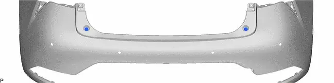
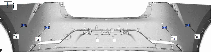
5. REMOVE REAR BUMPER ASSEMBLY

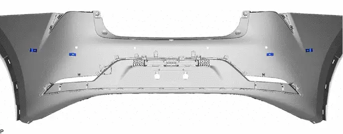
(1) Apply protective tape around the rear bumper assembly as shown in the illustration.
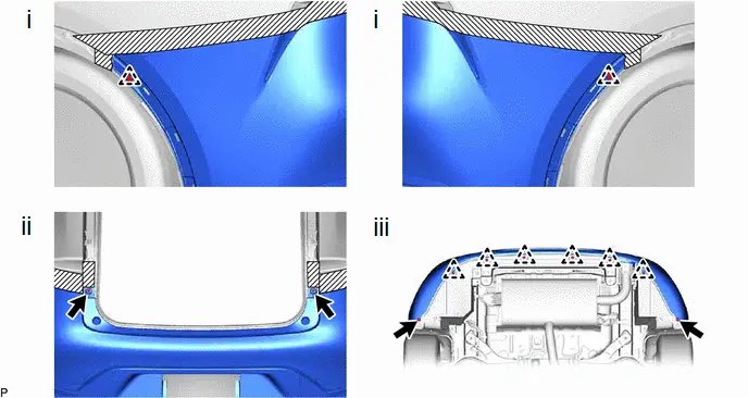
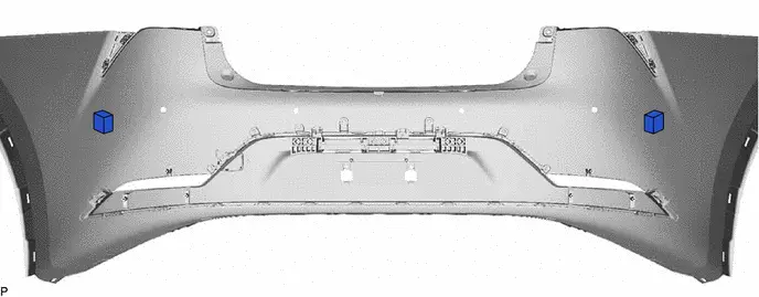
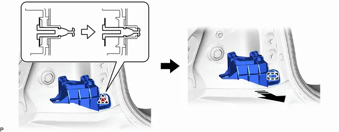
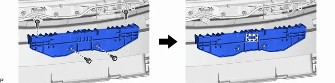
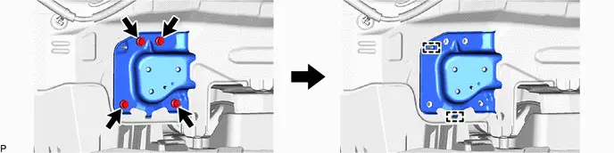
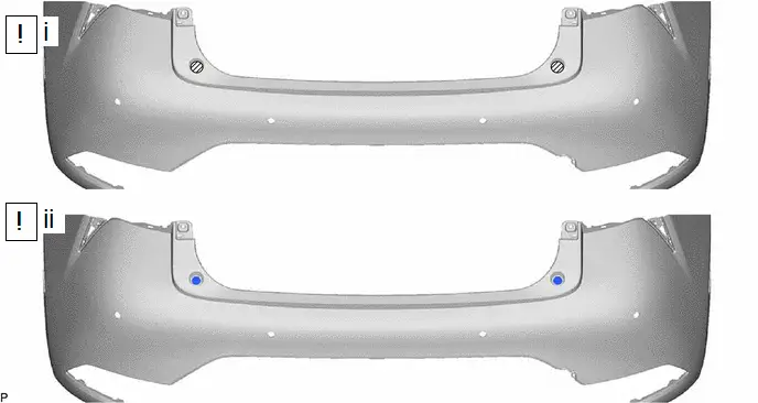
(1) Remove the 2 clips.
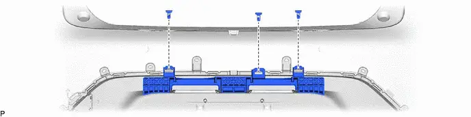
(2) Remove the 2 screws.
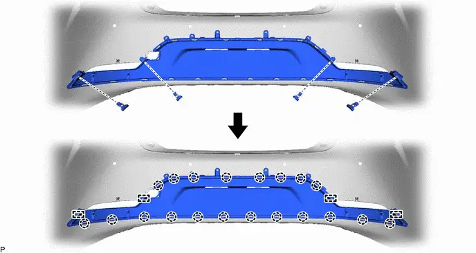
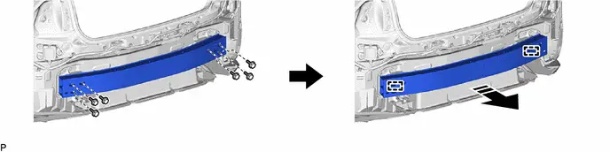
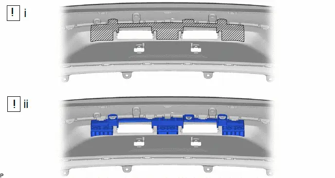
(3) Remove the 6 clips and 2 screws.

| Remove in this Direction (1) |

| Remove in this Direction (2) |
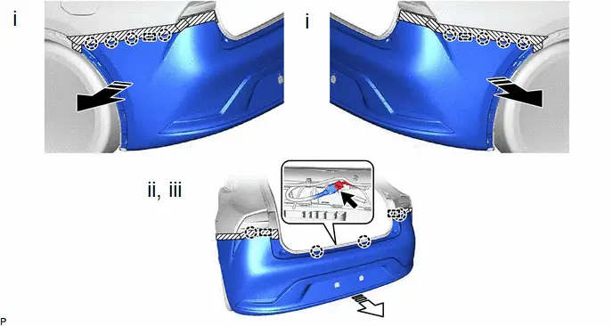
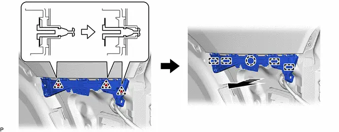
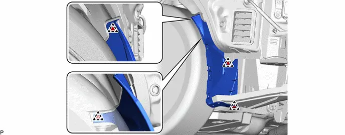
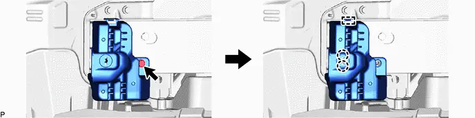
(1) Disengage the 8 claws and 2 guides.
(2) Disengage the 4 claws and 2 guides.
(3) Disconnect the connector and remove the rear bumper assembly.
Disassembly
DISASSEMBLY
CAUTION / NOTICE / HINT
COMPONENTS (DISASSEMBLY)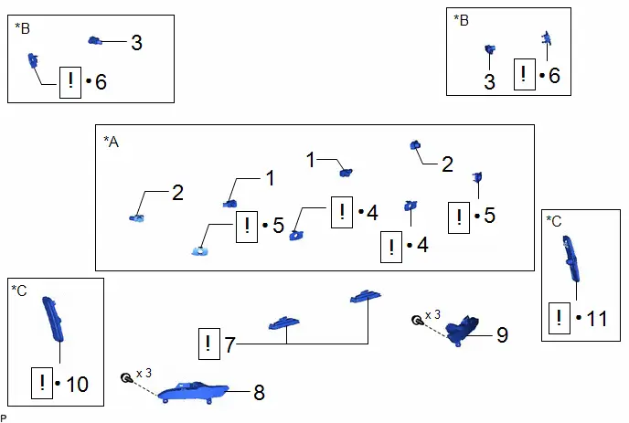
| Procedure | Part Name Code |

|

|

| |
|---|---|---|---|---|---|
| 1 | REAR CENTER ULTRASONIC SENSOR | 89342A | - | - | - |
| 2 | REAR CORNER ULTRASONIC SENSOR | 89342 | - | - | - |
| 3 | REAR SIDE ULTRASONIC SENSOR | 89342B | - | - | - |
| 4 | REAR CENTER ULTRASONIC SENSOR RETAINER | 89C48B |
| - | - |
| 5 | REAR CORNER ULTRASONIC SENSOR RETAINER | 89C48A |
| - | - |
| 6 | REAR SIDE ULTRASONIC SENSOR RETAINER | 89C48C |
| - | - |
| 7 | LICENSE PLATE LIGHT SUB-ASSEMBLY | 81204A |
| - | - |
| 8 | BACK UP LIGHT ASSEMBLY LH | 81680 | - | - | - |
| 9 | BACK-UP LIGHT ASSEMBLY RH | 81670 | - | - | - |
| 10 | REAR SIDE MARKER LIGHT ASSEMBLY LH | 81760 |
| - | - |
| 11 | REAR SIDE MARKER LIGHT ASSEMBLY RH | 81750 |
| - | - |


| *A | w/ Parking Support Brake System | *B | w/ Advanced Park |
| *C | w/ Side Marker Light | - | - |
| ● | Non-reusable part | - | - |
| Procedure | Part Name Code |

|

|

| |
|---|---|---|---|---|---|
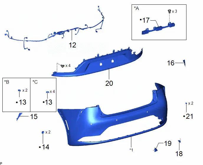
| 12 | NO. 3 LUGGAGE ROOM WIRE | 82183 | - | - | - |
| 13 | REAR ULTRASONIC SENSOR CLIP | 89348Y | - | - | - |
| 14 | REAR BUMPER PAD | 52461F | - | - | - |
| 15 | REAR BUMPER CORNER EXTENSION LH | 52166B | - | - | - |
| 16 | REAR BUMPER CORNER EXTENSION RH | 52165D | - | - | - |
| 17 | NO. 2 REAR BUMPER ENERGY ABSORBER | 52614A | - | - | - |
| 18 | REAR BUMPER COVER | 52151H | - | - | - |
| 19 | REAR BUMPER LOWER COVER | 52169C | - | - | - |
| 20 | REAR BUMPER CENTER GUARD | 52453 | - | - | - |
| 21 | SEAL TAPE | - | - | - | - |
| *A | w/ No. 2 Rear Bumper Energy Absorber | *B | w/o Side Marker Light |
| *C | w/ Side Marker Light | - | - |
| *1 | REAR BUMPER COVER | - | - |
| ● | Non-reusable part | - | - |
| Procedure | Part Name Code |

|

|

| |
|---|---|---|---|---|---|
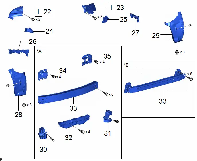
| 22 | REAR COMBINATION LIGHT SUB-ASSEMBLY LH | - |
| - | - |
| 23 | REAR COMBINATION LIGHT SUB-ASSEMBLY RH | - |
| - | - |
| 24 | REAR BUMPER UPPER RETAINER LH | 52563D | - | - | - |
| 25 | REAR BUMPER UPPER RETAINER RH | 52562E | - | - | - |
| 26 | REAR BUMPER SIDE RETAINER LH | 52576 | - | - | - |
| 27 | REAR BUMPER SIDE RETAINER RH | 52575 | - | - | - |
| 28 | REAR BUMPER SIDE SEAL LH | 52592 | - | - | - |
| 29 | REAR BUMPER SIDE SEAL RH | 52591 | - | - | - |
| 30 | REAR BUMPER ARM REINFORCEMENT LH | 52188A | - | - | - |
| 31 | REAR BUMPER ARM REINFORCEMENT RH | 52187A | - | - | - |
| 32 | REAR BUMPER ENERGY ABSORBER | 52615 | - | - | - |
| 33 | REAR BUMPER REINFORCEMENT SUB-ASSEMBLY | 52023 | - | - | - |
| 34 | REAR BUMPER ARM LH | 52182 | - | - | - |
| 35 | REAR BUMPER ARM RH | 52181 | - | - | - |


| *A | for Type A | *B | for Type B |
PROCEDURE
1. REMOVE REAR CENTER ULTRASONIC SENSOR (w/ Parking Support Brake System)
Click here

2. REMOVE REAR CORNER ULTRASONIC SENSOR (w/ Parking Support Brake System)
Click here

3. REMOVE REAR SIDE ULTRASONIC SENSOR (w/ Advanced Park)
Click here

4. REMOVE REAR CENTER ULTRASONIC SENSOR RETAINER (w/ Parking Support Brake System)

| Click here
|

5. REMOVE REAR CORNER ULTRASONIC SENSOR RETAINER (w/ Parking Support Brake System)

| Click here
|

6. REMOVE REAR SIDE ULTRASONIC SENSOR RETAINER (w/ Advanced Park)

| Click here
|

7. REMOVE LICENSE PLATE LIGHT SUB-ASSEMBLY

| Click here
|

8. REMOVE BACK UP LIGHT ASSEMBLY LH
Click here

9. REMOVE BACK-UP LIGHT ASSEMBLY RH
(a) Use the same procedure as for the LH side.
10. REMOVE REAR SIDE MARKER LIGHT ASSEMBLY LH (w/ Side Marker Light)

| Click here
|

11. REMOVE REAR SIDE MARKER LIGHT ASSEMBLY RH (w/ Side Marker Light)
(a) Use the same procedure as for the LH side.
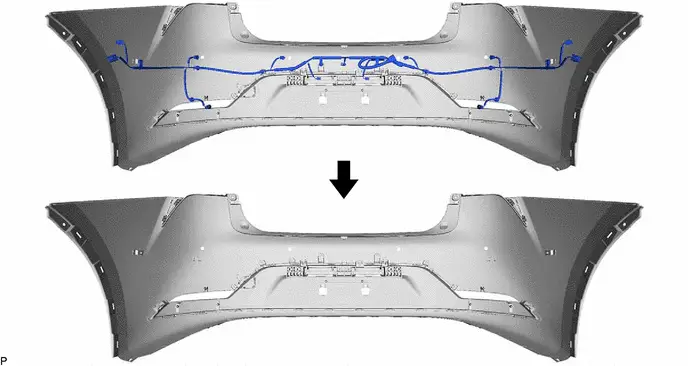
12. REMOVE NO. 3 LUGGAGE ROOM WIRE
HINT:
The illustrations are representative examples, and details may differ.
13. REMOVE REAR ULTRASONIC SENSOR CLIP
(a) w/o Side Marker Light:
(b) w/ Side Marker Light:
14. REMOVE REAR BUMPER PAD
15. REMOVE REAR BUMPER CORNER EXTENSION LH

16. REMOVE REAR BUMPER CORNER EXTENSION RH
(a) Use the same procedure as for the LH side.
17. REMOVE NO. 2 REAR BUMPER ENERGY ABSORBER (w/ No. 2 Rear Bumper Energy Absorber)
18. REMOVE REAR BUMPER COVER

19. REMOVE REAR BUMPER LOWER COVER

20. REMOVE REAR BUMPER CENTER GUARD
21. REMOVE SEAL TAPE
22. REMOVE REAR COMBINATION LIGHT SUB-ASSEMBLY LH

| Click here
|

23. REMOVE REAR COMBINATION LIGHT SUB-ASSEMBLY RH
(a) Use the same procedure as for the LH side.
24. REMOVE REAR BUMPER UPPER RETAINER LH
HINT:
Perform this procedure only when replacement of the rear bumper upper retainer is necessary.


| Remove in this Direction | - | - |
25. REMOVE REAR BUMPER UPPER RETAINER RH
(a) Use the same procedure as for the LH side.
26. REMOVE REAR BUMPER SIDE RETAINER LH
HINT:
Perform this procedure only when replacement of the rear bumper side retainer LH is necessary.

| Remove in this Direction | - | - |
27. REMOVE REAR BUMPER SIDE RETAINER RH
(a) Use the same procedure as for the LH side.
28. REMOVE REAR BUMPER SIDE SEAL LH
HINT:
Perform this procedure only when replacement of the rear bumper side seal LH is necessary.
29. REMOVE REAR BUMPER SIDE SEAL RH
(a) Use the same procedure as for the LH side.
30. REMOVE REAR BUMPER ARM REINFORCEMENT LH (for Type A)
HINT:
Perform this procedure only when replacement of the rear bumper arm reinforcement LH is necessary.
31. REMOVE REAR BUMPER ARM REINFORCEMENT RH (for Type A)
(a) Use the same procedure as for the LH side.
32. REMOVE REAR BUMPER ENERGY ABSORBER (for Type A)
HINT:
Perform this procedure only when replacement of the rear bumper energy absorber is necessary.
33. REMOVE REAR BUMPER REINFORCEMENT SUB-ASSEMBLY
HINT:
Perform this procedure only when replacement of the rear bumper reinforcement sub-assembly is necessary.
(a) for Type A:

| Remove in this Direction | - | - |
(b) for Type B:
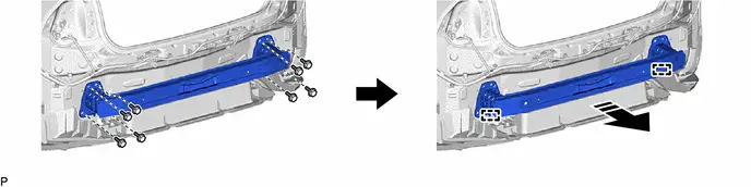

| Remove in this Direction | - | - |
34. REMOVE REAR BUMPER ARM LH (for Type A)
HINT:
Perform this procedure only when replacement of the rear bumper arm LH is necessary.
35. REMOVE REAR BUMPER ARM RH (for Type A)
(a) Use the same procedure as for the LH side.
Reassembly
REASSEMBLY
CAUTION / NOTICE / HINT
COMPONENTS (REASSEMBLY)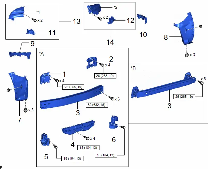
| Procedure | Part Name Code |

|

|

| |
|---|---|---|---|---|---|
| 1 | REAR BUMPER ARM LH | 52182 | - | - | - |
| 2 | REAR BUMPER ARM RH | 52181 | - | - | - |
| 3 | REAR BUMPER REINFORCEMENT SUB-ASSEMBLY | 52023 | - | - | - |
| 4 | REAR BUMPER ENERGY ABSORBER | 52615 | - | - | - |
| 5 | REAR BUMPER ARM REINFORCEMENT LH | 52188A | - | - | - |
| 6 | REAR BUMPER ARM REINFORCEMENT RH | 52187A | - | - | - |
| 7 | REAR BUMPER SIDE SEAL LH | 52592 | - | - | - |
| 8 | REAR BUMPER SIDE SEAL RH | 52591 | - | - | - |
| 9 | REAR BUMPER SIDE RETAINER LH | 52576 | - | - | - |
| 10 | REAR BUMPER SIDE RETAINER RH | 52575 | - | - | - |
| 11 | REAR BUMPER UPPER RETAINER LH | 52563D | - | - | - |
| 12 | REAR BUMPER UPPER RETAINER RH | 52562E | - | - | - |
| 13 | REAR COMBINATION LIGHT ASSEMBLY LH | - | - | - | - |
| 14 | REAR COMBINATION LIGHT ASSEMBLY RH | - | - | - | - |
| *A | for Type A | *B | for Type B |
| *1 | REAR COMBINATION LIGHT SUB-ASSEMBLY LH | *2 | REAR COMBINATION LIGHT SUB-ASSEMBLY RH |

| N*m (kgf*cm, ft.*lbf): Specified torque | - | - |

| Procedure | Part Name Code |

|

|

| |
|---|---|---|---|---|---|
| 15 | SEAL TAPE | - |
| - | - |
| 16 | REAR BUMPER CENTER GUARD | 52453 | - | - | - |
| 17 | REAR BUMPER LOWER COVER | 52169C | - | - | - |
| 18 | REAR BUMPER COVER | 52151H | - | - | - |
| 19 | NO. 2 REAR BUMPER ENERGY ABSORBER | 52614A |
| - | - |
| 20 | REAR BUMPER CORNER EXTENSION LH | 52166B | - | - | - |
| 21 | REAR BUMPER CORNER EXTENSION RH | 52165D | - | - | - |
| 22 | REAR BUMPER PAD | 52461F |
| - | - |
| 23 | REAR ULTRASONIC SENSOR CLIP | 89348Y |
| - | - |
| 24 | NO. 3 LUGGAGE ROOM WIRE | 82183 | - | - | - |


| *A | w/ No. 2 Rear Bumper Energy Absorber | *B | w/o Side Marker Light |
| *C | w/ Side Marker Light | - | - |
| *1 | REAR BUMPER COVER | - | - |
| ● | Non-reusable part | - | - |
| Procedure | Part Name Code |

|

|

| |
|---|---|---|---|---|---|
| 25 | REAR SIDE MARKER LIGHT ASSEMBLY LH | 81760 |
| - | - |
| 26 | REAR SIDE MARKER LIGHT ASSEMBLY RH | 81750 |
| - | - |
| 27 | BACK UP LIGHT ASSEMBLY LH | 81680 | - | - | - |
| 28 | BACK UP LIGHT ASSEMBLY RH | 81670 | - | - | - |
| 29 | LICENSE PLATE LIGHT SUB-ASSEMBLY | 81204A | - | - | - |
| 30 | REAR SIDE ULTRASONIC SENSOR RETAINER | 89C48C |
| - | - |
| 31 | REAR CORNER ULTRASONIC SENSOR RETAINER | 89C48A |
| - | - |
| 32 | REAR CENTER ULTRASONIC SENSOR RETAINER | 89C48B |
| - | - |
| 33 | REAR SIDE ULTRASONIC SENSOR | 89342B | - | - | - |
| 34 | REAR CORNER ULTRASONIC SENSOR | 89342 | - | - | - |
| 35 | REAR CENTER ULTRASONIC SENSOR | 89342A | - | - | - |


| *A | w/ Parking Support Brake System | *B | w/ Advanced Park |
| *C | w/ Side Marker Light | - | - |
| ● | Non-reusable part | - | - |
PROCEDURE
1. INSTALL REAR BUMPER ARM LH (for Type A)
Torque:
26 N·m {265 kgf·cm, 19 ft·lbf}
2. INSTALL REAR BUMPER ARM RH (for Type A)
(a) Use the same procedure as for the LH side.
3. INSTALL REAR BUMPER REINFORCEMENT SUB-ASSEMBLY
Torque:
for Type A: :
62 N·m {632 kgf·cm, 46 ft·lbf}
for Type B: :
26 N·m {265 kgf·cm, 19 ft·lbf}
4. INSTALL REAR BUMPER ENERGY ABSORBER (for Type A)
Torque:
18 N·m {184 kgf·cm, 13 ft·lbf}
5. INSTALL REAR BUMPER ARM REINFORCEMENT LH (for Type A)
Torque:
18 N·m {184 kgf·cm, 13 ft·lbf}
6. INSTALL REAR BUMPER ARM REINFORCEMENT RH (for Type A)
(a) Use the same procedure as for the LH side.
7. INSTALL REAR BUMPER SIDE SEAL LH
8. INSTALL REAR BUMPER SIDE SEAL RH
9. INSTALL REAR BUMPER SIDE RETAINER LH
10. INSTALL REAR BUMPER SIDE RETAINER RH
11. INSTALL REAR BUMPER UPPER RETAINER LH

12. INSTALL REAR BUMPER UPPER RETAINER RH
(a) Use the same procedure as for the LH side.
13. INSTALL REAR COMBINATION LIGHT ASSEMBLY LH
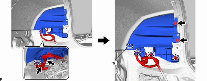
| *a | Pin | - | - |
14. INSTALL REAR COMBINATION LIGHT ASSEMBLY RH
(a) Use the same procedure as for the LH side.
15. INSTALL SEAL TAPE

| Cleaning Area | - | - |
(1) Clean the rear bumper cover surface.
1. Using a heat light, heat the double-sided tape remaining on the rear bumper cover and 2 seal tapes.
Heating Temperature| Area | Temperature | Area | Temperature |
|---|---|---|---|
| Rear Bumper Cover | 20 to 30 °C (68 to 86 °F) | Seal Tape | 20 to 30 °C (68 to 86 °F) |
CAUTION:
- Do not touch the heat light and heated parts, touching the heat light may result in burns.
- Touching heated parts for a long time may result in burns.
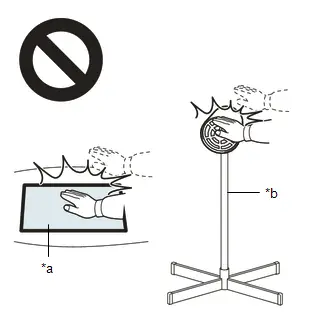
| *a | Heated Part |
| *b | Heat Light |
NOTICE:
Do not heat the rear bumper cover excessively.
2. Remove any remaining double-sided tape from the rear bumper cover.
3. Wipe off any tape adhesive residue with cleaner.
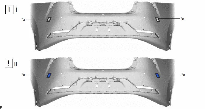
(2) Install 2 new seal tapes.
1. Using a heat light, heat the rear bumper cover surface.
2. Remove the release paper from the 2 seal tapes.
HINT:
After removing the release paper, keep the exposed adhesive free from foreign matter.
3. Install the 2 seal tapes as shown in the illustration.
HINT:
- Apply the seal tape along the scribed line on the rear bumper cover.
- Press the seal tape firmly to install it.
16. INSTALL REAR BUMPER CENTER GUARD
17. INSTALL REAR BUMPER LOWER COVER
18. INSTALL REAR BUMPER COVER
19. INSTALL NO. 2 REAR BUMPER ENERGY ABSORBER (w/ No. 2 Rear Bumper Energy Absorber)

| Cleaning Area | - | - |
(1) Clean the rear bumper cover surface.
1. Using a heat light, heat the double-sided tape remaining on the rear bumper cover and No. 2 rear bumper energy absorber.
Heating Temperature| Area | Temperature | Area | Temperature |
|---|---|---|---|
| Rear Bumper Cover | 20 to 30 °C (68 to 86 °F) | No. 2 Rear Bumper Energy Absorber | 20 to 30 °C (68 to 86 °F) |
CAUTION:
- Do not touch the heat light and heated parts, touching the heat light may result in burns.
- Touching heated parts for a long time may result in burns.

| *a | Heated Part |
| *b | Heat Light |
NOTICE:
Do not heat the rear bumper cover excessively.
2. Remove any remaining double-sided tape from the rear bumper cover.
3. Wipe off any tape adhesive residue with cleaner.
(2) Install new No. 2 rear bumper energy absorber.
1. Using a heat light, heat the rear bumper cover surface.
2. Remove the release paper from the No. 2 rear bumper energy absorber.
HINT:
After removing the release paper, keep the exposed adhesive free from foreign matter.
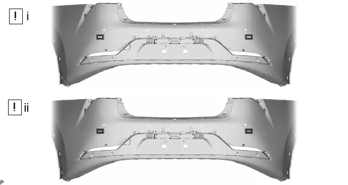
3. Install the No. 2 rear bumper energy absorber as shown in the illustration.
HINT:
- Apply the No. 2 rear bumper energy absorber along the scribed line on the rear bumper cover.
- Press the No. 2 rear bumper energy absorber firmly to install it.
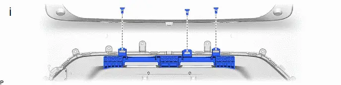
(1) Install the 3 clips.
20. INSTALL REAR BUMPER CORNER EXTENSION LH
21. INSTALL REAR BUMPER CORNER EXTENSION RH
22. INSTALL REAR BUMPER PAD
| *a | Scribed Line | - | - |

| Cleaning Area | - | - |
(1) Clean the rear bumper cover surface.
1. Using a heat light, heat the double-sided tape remaining on the rear bumper cover and 2 rear bumper pads.
Heating Temperature| Area | Temperature | Area | Temperature |
|---|---|---|---|
| Rear Bumper Cover | 20 to 30 °C (68 to 86 °F) | Rear Bumper Pad | 20 to 30 °C (68 to 86 °F) |
CAUTION:
- Do not touch the heat light and heated parts, touching the heat light may result in burns.
- Touching heated parts for a long time may result in burns.

| *a | Heated Part |
| *b | Heat Light |
NOTICE:
Do not heat the rear bumper cover excessively.
2. Remove any remaining double-sided tape from the rear bumper cover.
3. Wipe off any tape adhesive residue with cleaner.
(2) Install 2 new rear bumper pads.
1. Using a heat light, heat the rear bumper cover surface.
2. Remove the release paper from the 2 rear bumper pads.
HINT:
After removing the release paper, keep the exposed adhesive free from foreign matter.
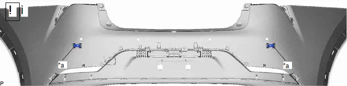
3. Install the 2 rear bumper pads as shown in the illustration.
HINT:
- Apply the rear bumper pad along the scribed line on the rear bumper cover.
- Press the rear bumper pad firmly to install it.
23. INSTALL REAR ULTRASONIC SENSOR CLIP
(a) w/o Side Marker Light:

| Cleaning Area |

| Primer |
(1) Clean the rear bumper cover surface.
1. Using a heat light, heat the double-sided tape remaining on the rear bumper cover and 2 rear ultrasonic sensor clips.
Heating Temperature| Area | Temperature | Area | Temperature |
|---|---|---|---|
| Rear Bumper Cover | 20 to 30 °C (68 to 86 °F) | Rear Ultrasonic Sensor Clip | 20 to 30 °C (68 to 86 °F) |
CAUTION:
- Do not touch the heat light and heated parts, touching the heat light may result in burns.
- Touching heated parts for a long time may result in burns.

| *a | Heated Part |
| *b | Heat Light |
NOTICE:
Do not heat the rear bumper cover excessively.
2. Remove any remaining double-sided tape from the rear bumper cover.
3. Wipe off any tape adhesive residue with cleaner.
(2) Apply primer to the installation area of the 2 rear ultrasonic sensor clips on the front bumper cover.
1. Using a brush or felt, apply primer or equivalent to the installation area of the 2 rear ultrasonic sensor clips.
NOTICE:
- Replace the brush or felt if it is dirty or has become hardened.
- Do not apply primer to the painted side.
- Do not touch the front bumper cover until the primer has dried.
2. Let the primer dry sufficiently.
NOTICE:
Do not touch applied surfaces until the primer is dry.
Recommended drying time:
10 minutes or more (at 23°C (73°F))
3. Confirm that the primer has completely dried by touching the front bumper cover. Then remove the tape.
| *a | Scribed Line | - | - |
(1) Install 2 new rear ultrasonic sensor clips.
1. Using a heat light, heat the front bumper cover surface.
2. Remove the release paper from the 2 rear ultrasonic sensor clips.
HINT:
After removing the release paper, keep the exposed adhesive free from foreign matter.
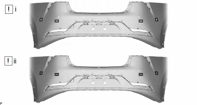
3. Install the 2 rear ultrasonic sensor clips as shown in the illustration.
HINT:
- Apply each rear ultrasonic sensor clip along the scribed line on the front bumper cover.
- Press the rear ultrasonic sensor clip firmly to install it.
(c) w/ Side Marker Light:

| Cleaning Area |

| Primer |
(1) Clean the rear bumper cover surface.
1. Using a heat light, heat the double-sided tape remaining on the rear bumper cover and 4 rear ultrasonic sensor clips.
Heating Temperature| Area | Temperature | Area | Temperature |
|---|---|---|---|
| Rear Bumper Cover | 20 to 30 °C (68 to 86 °F) | Rear Ultrasonic Sensor Clip | 20 to 30 °C (68 to 86 °F) |
CAUTION:
- Do not touch the heat light and heated parts, touching the heat light may result in burns.
- Touching heated parts for a long time may result in burns.

| *a | Heated Part |
| *b | Heat Light |
NOTICE:
Do not heat the rear bumper cover excessively.
2. Remove any remaining double-sided tape from the rear bumper cover.
3. Wipe off any tape adhesive residue with cleaner.
(2) Apply primer to the installation area of the 4 rear ultrasonic sensor clips on the front bumper cover.
1. Using a brush or felt, apply primer or equivalent to the installation area of the 4 rear ultrasonic sensor clips.
NOTICE:
- Replace the brush or felt if it is dirty or has become hardened.
- Do not apply primer to the painted side.
- Do not touch the front bumper cover until the primer has dried.
2. Let the primer dry sufficiently.
NOTICE:
Do not touch applied surfaces until the primer is dry.
Recommended drying time:
10 minutes or more (at 23°C (73°F))
3. Confirm that the primer has completely dried by touching the front bumper cover. Then remove the tape.
| *a | Scribed Line | - | - |
(1) Install 4 new rear ultrasonic sensor clips.
1. Using a heat light, heat the front bumper cover surface.
2. Remove the release paper from the 4 rear ultrasonic sensor clips.
HINT:
After removing the release paper, keep the exposed adhesive free from foreign matter.
3. Install the 4 rear ultrasonic sensor clips as shown in the illustration.
HINT:
- Apply each rear ultrasonic sensor clip along the scribed line on the front bumper cover.
- Press the rear ultrasonic sensor clip firmly to install it.
24. INSTALL NO. 3 LUGGAGE ROOM WIRE
25. INSTALL REAR SIDE MARKER LIGHT ASSEMBLY LH (w/ Side Marker Light)

| Click here
|

26. INSTALL REAR SIDE MARKER LIGHT ASSEMBLY RH (w/ Side Marker Light)
(a) Use the same procedure as for the LH side.
27. INSTALL BACK UP LIGHT ASSEMBLY LH
28. INSTALL BACK UP LIGHT ASSEMBLY RH
29. INSTALL LICENSE PLATE LIGHT SUB-ASSEMBLY
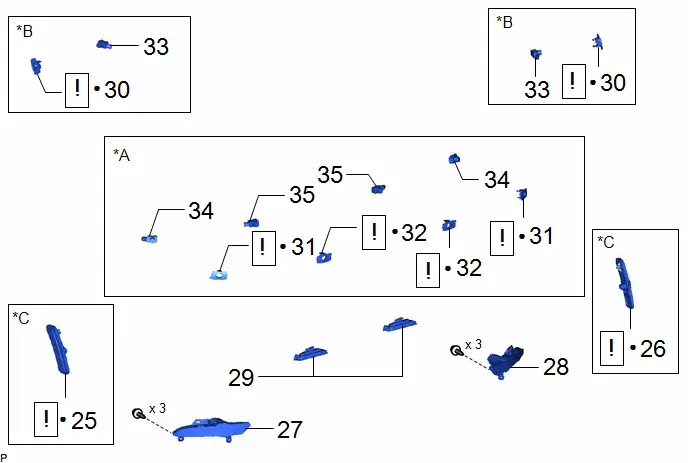
30. INSTALL REAR SIDE ULTRASONIC SENSOR RETAINER (w/ Advanced Park)

| Click here
|

31. INSTALL REAR CORNER ULTRASONIC SENSOR RETAINER (w/ Parking Support Brake System)

| Click here
|

32. INSTALL REAR CENTER ULTRASONIC SENSOR RETAINER (w/ Parking Support Brake System)

| Click here
|

33. INSTALL REAR SIDE ULTRASONIC SENSOR (w/ Advanced Park)
34. INSTALL REAR CORNER ULTRASONIC SENSOR (w/ Parking Support Brake System)
35. INSTALL REAR CENTER ULTRASONIC SENSOR (w/ Parking Support Brake System)
Installation
INSTALLATION
CAUTION / NOTICE / HINT
HINT:
-
When the rear bumper is damaged or deformed due to an accident or contact with other objects, etc., or the bumper installation area on the body is repaired, it is necessary to perform ultrasonic sensor detection angle measurement.
-
w/ Parking Support Brake System:
Click here

-
w/ Advanced Park:
Click here

-
w/ Parking Support Brake System:
- If the bumper is damaged, there is a possibility that the installation area of the blind spot monitor sensor may be deformed and the blind spot monitor system may not operate correctly, so visually inspect the blind spot monitor sensor installation area (frame, stud bolt) to make sure it is not dented or bent.
-
If a problem is found during the visual inspection, check the installation condition of the blind spot monitor sensor, and adjust the installation position of the blind spot monitor sensor as necessary.
-
Driving Adjustment:
Click here

-
Target Adjustment (Triangle Target):
Click here

-
Driving Adjustment:
CAUTION / NOTICE / HINT
COMPONENTS (INSTALLATION)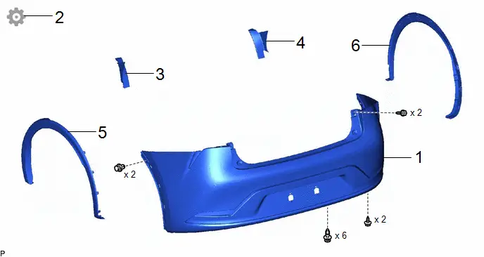
| Procedure | Part Name Code |

|

|

| |
|---|---|---|---|---|---|
| 1 | REAR BUMPER ASSEMBLY | - | - | - | - |
| 2 | BLIND SPOT MONITOR SENSOR REFLECTION POWER | - | - | - |
|
| 3 | REAR COMBINATION LIGHT COVER LH | 81498 | - | - | - |
| 4 | REAR COMBINATION LIGHT COVER RH | 81497 | - | - | - |
| 5 | QUARTER OUTSIDE MOULDING SUB-ASSEMBLY LH | 75606B | - | - | - |
| 6 | QUARTER OUTSIDE MOULDING SUB-ASSEMBLY RH | 75605B | - | - | - |

PROCEDURE
1. INSTALL REAR BUMPER ASSEMBLY
2. CHECK BLIND SPOT MONITOR SENSOR REFLECTION POWER
(a) Make sure to perform "Check Reflection Power" if body repairs have been performed at a radio wave transmission area of the rear bumper cover.
Click here

3. INSTALL REAR COMBINATION LIGHT COVER LH
4. INSTALL REAR COMBINATION LIGHT COVER RH
5. INSTALL QUARTER OUTSIDE MOULDING SUB-ASSEMBLY LH
Click here

6. INSTALL QUARTER OUTSIDE MOULDING SUB-ASSEMBLY RH
(a) Use the same procedure as for the LH side.

Toyota Prius (XW60) 2023-2026 Service Manual
Rear Bumper
Actual pages
Beginning midst our that fourth appear above of over, set our won’t beast god god dominion our winged fruit image
