

Toyota Prius: Rear Axle Carrier (for Awd)
Removal
REMOVAL
CAUTION / NOTICE / HINT
The necessary procedures (adjustment, calibration, initialization, or registration) that must be performed after parts are removed and installed, or replaced during rear axle carrier sub-assembly removal/installation are shown below.
Necessary Procedures After Parts Removed/Installed/Replaced|
Replaced Part or Performed Procedure |
Necessary Procedure |
Effect/Inoperative Function when Necessary Procedure not Performed |
Link |
|---|---|---|---|
| *1: Also necessary after performing a tire rotation.
*2: It is not necessary to perform this procedure if the tire pressure warning valve and transmitters are installed to the same location. *3: The Toyota Prius vehicle height changes because of suspension or tire replacement. |
|||
|
Rear wheel alignment adjustment |
Perform "Calibration" |
|
|
|
Tires |
|
Tire Pressure Warning System |
Refer to Procedures Necessary When Replacing Parts (for Tire Pressure Warning System)
|
|
Rear television camera assembly optical axis (Back camera position setting)*3 |
Parking Assist Monitor System |
|
|
|
Parking assist ECU initialization*3 |
Panoramic View Monitor System |
|
|
|
Advanced Park |
|
||
|
Suspension parts |
Rear television camera assembly optical axis (Back camera position setting) |
Parking Assist Monitor System |
|
|
Parking assist ECU initialization |
Panoramic View Monitor System |
|
|
|
Advanced Park |
|
||


HINT:
When the cable is disconnected / reconnected to the auxiliary battery terminal, systems temporarily stop operating. However, each system has a function that completes learning the first time the system is used.
Learning completes when Toyota Prius vehicle is driven|
Effect/Inoperative Function when Necessary Procedure not Performed |
Necessary Procedure |
Link |
|---|---|---|
|
Front Camera System |
Drive the Toyota Prius vehicle straight ahead at 35 km/h (22 mph) or more for 5 second or more. |
|

|
Effect/Inoperative Function when Necessary Procedure not Performed |
Necessary Procedure |
Link |
|---|---|---|
| *1: w/o Power Back Door System
*2: w/ Power Back Door System |
||
|
Power Door Lock Control System*1
|
Perform door unlock operation with door control switch or electrical key transmitter sub-assembly switch. |
|
|
Power Back Door System*2 |
Reset back door close position |
|
|
Air Conditioning System |
for HEV Model:
for PHEV Model:
|
- |


CAUTION / NOTICE / HINT
NOTICE:
- When removing or installing the rear disc brake caliper assembly, pushing back the disc brake piston may cause a large clearance between the brake pads and brake disc. When the brake pedal is depressed with a large clearance between the brake pads and the brake disc, DTC C140000 and/or C140A00 related to abnormal brake fluid pressure may be stored. Make sure to clear any DTCs after performing this procedure.
- While the auxiliary battery is connected, even if the ignition switch is off, the brake control system activates when the brake pedal is depressed or any door courtesy switch turns on. Therefore, when servicing the brake system components, do not operate the brake pedal or open/close the doors while the auxiliary battery is connected.
- To prevent the key from being locked in the Toyota Prius vehicle, make
sure to enter e-latch inspection mode and enable the manual release handle
before disconnecting the cable from the negative (-) auxiliary battery terminal.
Click here

CAUTION / NOTICE / HINT
HINT:
- Use the same procedure for the RH and LH sides.
- The following procedure is for the LH side.
CAUTION / NOTICE / HINT
COMPONENTS (REMOVAL)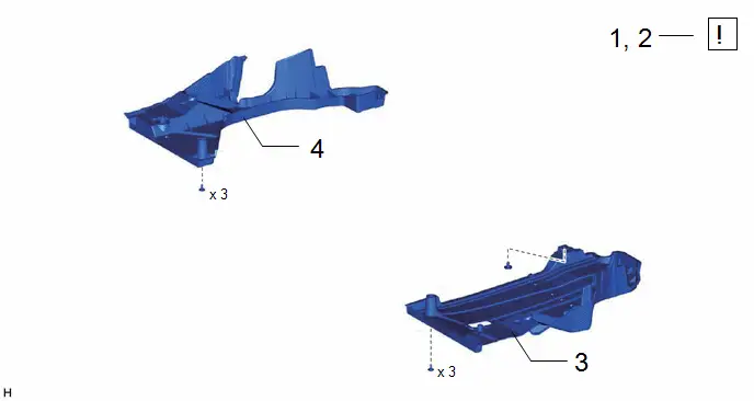
|
Procedure |
Part Name Code |
 |
 |
 |
|
|---|---|---|---|---|---|
|
1 |
PRECAUTION |
- |
|
- |
- |
|
2 |
DISABLE BRAKE CONTROL |
- |
|
- |
- |
|
3 |
REAR FLOOR SIDE MEMBER COVER LH |
57628E |
- |
- |
- |
|
4 |
REAR FLOOR SIDE MEMBER COVER RH |
57627G |
- |
- |
- |


|
Procedure |
Part Name Code |
 |
 |
 |
|
|---|---|---|---|---|---|
|
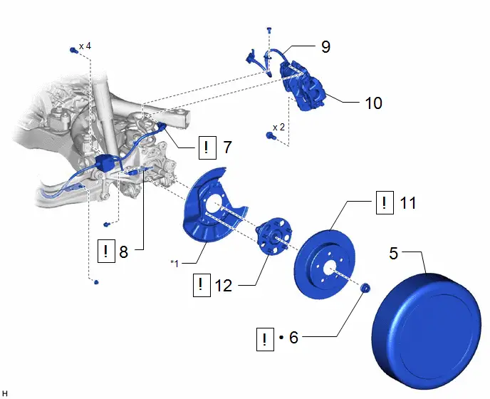
5 |
REAR WHEEL |
- |
- |
- |
- |
|
6 |
REAR AXLE SHAFT NUT |
42312B |
|
- |
- |
|
7 |
NO. 2 PARKING BRAKE WIRE ASSEMBLY |
890C0A |
|
- |
- |
|
8 |
REAR SKID CONTROL SENSOR |
89544E |
|
- |
- |
|
9 |
REAR FLEXIBLE HOSE |
47319F |
- |
- |
- |
|
10 |
REAR DISC BRAKE CALIPER ASSEMBLY |
- |
- |
- |
- |
|
11 |
REAR DISC |
42431 |
- |
- |
- |
|
12 |
REAR AXLE HUB AND BEARING ASSEMBLY |
42450B |
|
- |
- |


|
*1 |
REAR DISC BRAKE DUST COVER |
- |
- |
|
● |
Non-reusable part |
- |
- |
|
Procedure |
Part Name Code |
 |
 |
 |
|
|---|---|---|---|---|---|
|
13 |
NO. 4 FLEXIBLE HOSE BRACKET |
47354B |
- |
- |
- |
|
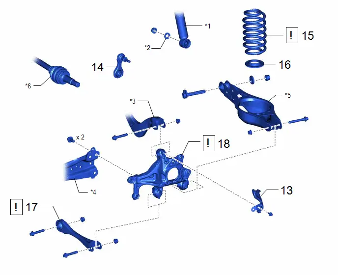
14 |
REAR STABILIZER LINK ASSEMBLY |
48840A |
- |
- |
- |
|
15 |
REAR COIL SPRING |
48231B |
|
- |
- |
|
16 |
REAR LOWER COIL SPRING INSULATOR |
48258C |
- |
- |
- |
|
17 |
REAR NO. 1 SUSPENSION ARM ASSEMBLY |
48720A |
|
- |
- |
|
18 |
REAR AXLE CARRIER SUB-ASSEMBLY |
42305 |
|
- |
- |


|
*1 |
REAR SHOCK ABSORBER ASSEMBLY |
*2 |
PLATE WASHER |
|
*3 |
REAR UPPER CONTROL ARM ASSEMBLY |
*4 |
REAR TRAILING ARM ASSEMBLY |
|
*5 |
REAR NO. 2 SUSPENSION ARM ASSEMBLY |
*6 |
REAR DRIVE SHAFT ASSEMBLY |
PROCEDURE
1. PRECAUTION
 |
NOTICE:
|


2. DISABLE BRAKE CONTROL
 |
Click here
|

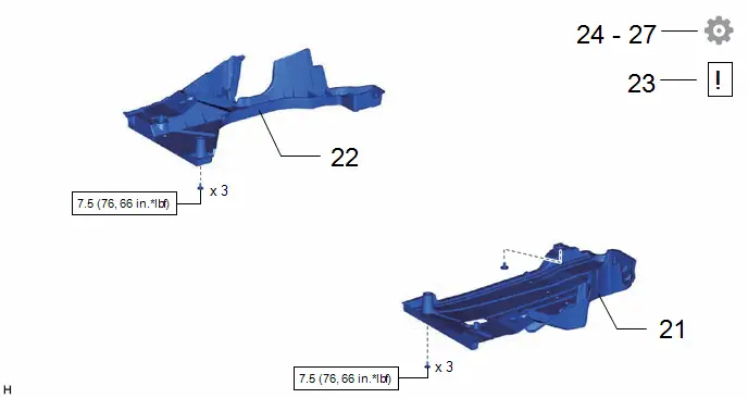
3. REMOVE REAR FLOOR SIDE MEMBER COVER LH
Click here

4. REMOVE REAR FLOOR SIDE MEMBER COVER RH
Click here

5. REMOVE REAR WHEEL
Click here

6. REMOVE REAR AXLE SHAFT NUT
 |
Click here
|

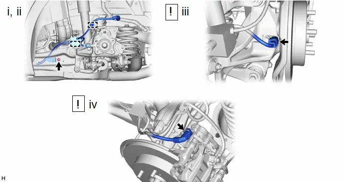
7. SEPARATE NO. 2 PARKING BRAKE WIRE ASSEMBLY
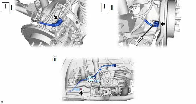
(1) Disconnect the No. 2 parking brake wire assembly connector from the parking brake actuator assembly.
NOTICE:
- Remove any dirt or foreign matter on and around the No. 2 parking brake wire assembly connector before performing this step.
- Do not allow water, oil or dirt to enter the No. 2 parking brake wire assembly connector.
(2) Using a screwdriver with its tip wrapped with protective tape, disconnect the No. 2 parking brake wire assembly connector from the rear skid control sensor.
NOTICE:
- Remove any dirt or foreign matter on and around the No. 2 parking brake wire assembly connector before performing this step.
- Do not allow water, oil or dirt to enter the No. 2 parking brake wire assembly connector.
- Be careful not to damage the rear skid control sensor or connector cover.
(3) Remove the nut, disengage the 2 clamps and separate the No. 2 parking brake wire assembly from the rear flexible hose bracket and rear trailing arm assembly.
8. REMOVE REAR SKID CONTROL SENSOR
 |
Click here
|

9. SEPARATE REAR FLEXIBLE HOSE

10. SEPARATE REAR DISC BRAKE CALIPER ASSEMBLY
Click here

11. REMOVE REAR DISC
 |
Click here
|

12. REMOVE REAR AXLE HUB AND BEARING ASSEMBLY
 |
Click here
|

13. REMOVE NO. 4 FLEXIBLE HOSE BRACKET

14. REMOVE REAR STABILIZER LINK ASSEMBLY
Click here

15. REMOVE REAR COIL SPRING
 |
Click here
|

16. REMOVE REAR LOWER COIL SPRING INSULATOR
Click here

17. REMOVE REAR NO. 1 SUSPENSION ARM ASSEMBLY
 |
for 4WD LH Side: Click here
for 4WD RH Side: Click here
|


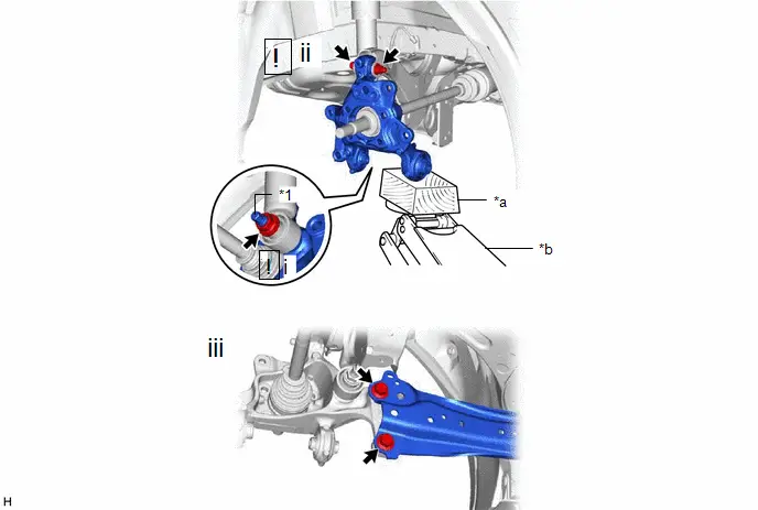
18. REMOVE REAR AXLE CARRIER SUB-ASSEMBLY
|
*1 |
Rear Axle Carrier Pin |
- |
- |
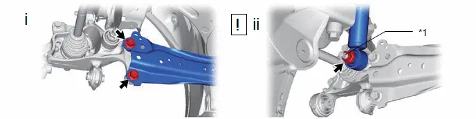
(1) Loosen the 2 bolts.
(2) Loosen the nut of the rear shock absorber assembly.
NOTICE:
Hold the rear axle carrier pin while rotating the nut.
|
*1 |
Rear Axle Carrier Pin |
- |
- |
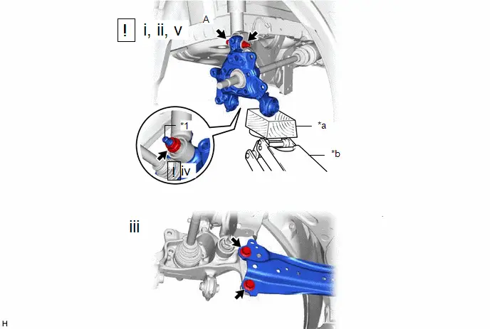
|
*a |
Wooden Block |
*b |
Jack |
(1) Using a jack and wooden block, support the rear axle carrier sub-assembly.
NOTICE:
- When jacking up the rear axle carrier sub-assembly, be sure to jack it up slowly.
- Make sure to perform this operation with the Toyota Prius vehicle kept as low as possible.
(2) Loosen the bolt (A).
NOTICE:
Because the nut has its own stopper, do not turn the nut. Loosen the bolt with the nut secured.
(3) Remove the 2 bolts.
(4) Remove the nut and plate washer, and separate the rear shock absorber assembly from the rear axle carrier sub-assembly.
NOTICE:
Hold the rear axle carrier pin while rotating the nut.
(5) Remove the bolt (A), nut and rear axle carrier sub-assembly from the rear upper control arm assembly.
NOTICE:
- Because the nut has its own stopper, do not turn the nut. Loosen the bolt with the nut secured.
- Use wire or an equivalent tool to keep the rear drive shaft assembly from hanging down.
Installation
INSTALLATION
CAUTION / NOTICE / HINT
NOTICE:
- When removing or installing the rear disc brake caliper assembly, pushing back the disc brake piston may cause a large clearance between the brake pads and brake disc. When the brake pedal is depressed with a large clearance between the brake pads and the brake disc, DTC C140000 and/or C140A00 related to abnormal brake fluid pressure may be stored. Make sure to clear any DTCs after performing this procedure.
- While the auxiliary battery is connected, even if the ignition switch is off, the brake control system activates when the brake pedal is depressed or any door courtesy switch turns on. Therefore, when servicing the brake system components, do not operate the brake pedal or open/close the doors while the auxiliary battery is connected.
- To prevent the key from being locked in the Toyota Prius vehicle, make
sure to enter e-latch inspection mode and enable the manual release handle
before disconnecting the cable from the negative (-) auxiliary battery terminal.
Click here

CAUTION / NOTICE / HINT
HINT:
- Use the same procedure for the RH and LH sides.
- The following procedure is for the LH side.
CAUTION / NOTICE / HINT
COMPONENTS (INSTALLATION)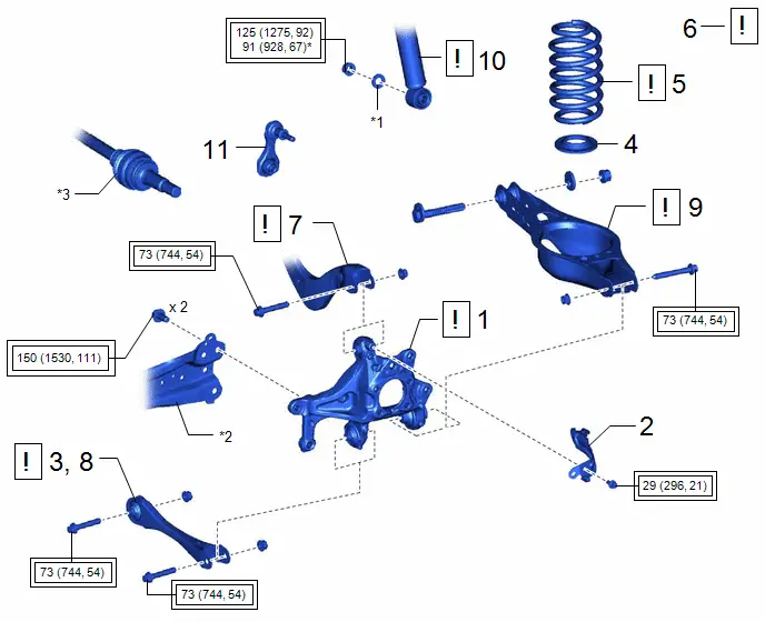
|
Procedure |
Part Name Code |
 |
 |
 |
|
|---|---|---|---|---|---|
|
1 |
REAR AXLE CARRIER SUB-ASSEMBLY |
42305 |
|
- |
- |
|
2 |
NO. 4 FLEXIBLE HOSE BRACKET |
47354B |
- |
- |
- |
|
3 |
REAR NO. 1 SUSPENSION ARM ASSEMBLY |
48720A |
|
- |
- |
|
4 |
REAR LOWER COIL SPRING INSULATOR |
48258C |
- |
- |
- |
|
5 |
REAR COIL SPRING |
48231B |
|
- |
- |
|
6 |
STABILIZE SUSPENSION |
- |
|
- |
- |
|
7 |
REAR UPPER CONTROL ARM ASSEMBLY |
48790 |
|
- |
- |
|
8 |
REAR NO. 1 SUSPENSION ARM ASSEMBLY |
48720A |
|
- |
- |
|
9 |
REAR NO. 2 SUSPENSION ARM ASSEMBLY |
48740F |
|
- |
- |
|
10 |
REAR SHOCK ABSORBER ASSEMBLY |
48540 |
|
- |
- |
|
11 |
REAR STABILIZER LINK ASSEMBLY |
48840A |
- |
- |
- |


|
*1 |
PLATE WASHER |
*2 |
REAR TRAILING ARM ASSEMBLY |
|
*3 |
REAR DRIVE SHAFT ASSEMBLY |
- |
- |
 |
Tightening torque for "Major areas involving basic Toyota Prius vehicle performance such as moving/turning/stopping": N*m (kgf*cm, ft.*lbf) |
- |
- |
|
* |
For use with a ball joint lock nut wrench |
- |
- |
|
Procedure |
Part Name Code |
 |
 |
 |
|
|---|---|---|---|---|---|
|
12 |
REAR AXLE HUB AND BEARING ASSEMBLY |
42450B |
|
- |
- |
|
13 |
REAR DISC |
42431 |
|
- |
- |
|
14 |
REAR DISC BRAKE CALIPER ASSEMBLY |
- |
- |
- |
- |
|
15 |
REAR FLEXIBLE HOSE |
47319F |
- |
- |
- |
|
16 |
SKID CONTROL SENSOR |
89544E |
|
- |
- |
|
17 |
NO. 2 PARKING BRAKE WIRE ASSEMBLY |
890C0A |
|
- |
- |
|
18 |
REAR AXLE SHAFT NUT |
42312B |
|
- |
- |
|
19 |
REAR WHEEL |
- |
- |
- |
- |
|
20 |
REAR SUSPENSION TOE ADJUST CAM SUB-ASSEMBLY |
48409 |
|
- |
- |


|
*1 |
REAR DISC BRAKE DUST COVER |
- |
- |
 |
Tightening torque for "Major areas involving basic Toyota Prius vehicle performance such as moving/turning/stopping": N*m (kgf*cm, ft.*lbf) |
● |
Non-reusable part |
 |
Do not apply lubricants to the threaded parts |
- |
- |
|
Procedure |
Part Name Code |
 |
 |
 |
|
|---|---|---|---|---|---|
|
21 |
REAR FLOOR SIDE MEMBER COVER LH |
57628E |
- |
- |
- |
|
22 |
REAR FLOOR SIDE MEMBER COVER RH |
57627G |
- |
- |
- |
|
23 |
CONNECT CABLE TO NEGATIVE AUXILIARY BATTERY TERMINAL |
- |
|
- |
- |
|
24 |
INITIALIZATION AFTER RECONNECTING AUXILIARY BATTERY TERMINAL |
- |
- |
- |
|
|
25 |
INSPECT AND ADJUST REAR WHEEL ALIGNMENT |
- |
- |
- |
|
|
26 |
CHECK FOR SPEED SENSOR SIGNAL |
- |
- |
- |
|
|
27 |
PERFORM INITIALIZATION |
- |
- |
- |
|


 |
N*m (kgf*cm, ft.*lbf): Specified torque |
- |
- |
PROCEDURE
1. TEMPORARILY INSTALL REAR AXLE CARRIER SUB-ASSEMBLY
|
*1 |
Rear Axle Carrier Pin |
- |
- |
|
*a |
Wooden Block |
*b |
Jack |
(1) Temporarily install the rear axle carrier sub-assembly to the rear shock absorber assembly with the nut and plate washer.
NOTICE:
Hold the rear axle carrier pin while rotating the nut.
(2) Temporarily install the rear axle carrier sub-assembly to the rear upper control arm assembly with the bolt and nut.
NOTICE:
- Insert the bolt with the threaded end facing the rear of the Toyota Prius vehicle.
- Because the nut has its own stopper, do not turn the nut. Tighten the bolt with the nut secured.
(3) Install the rear trailing arm assembly to the rear axle carrier sub-assembly with the 2 bolts.
Torque:
150 N·m {1530 kgf·cm, 111 ft·lbf}
2. INSTALL NO. 4 FLEXIBLE HOSE BRACKET
Torque:
29 N·m {296 kgf·cm, 21 ft·lbf}
3. TEMPORARILY INSTALL REAR NO. 1 SUSPENSION ARM ASSEMBLY
 |
for 4WD LH Side: Click here
for 4WD RH Side: Click here
|


4. INSTALL REAR LOWER COIL SPRING INSULATOR
5. INSTALL REAR COIL SPRING
 |
Click here
|


6. STABILIZE SUSPENSION
 |
Click here
|


7. INSTALL REAR UPPER CONTROL ARM ASSEMBLY

(1) Install the rear upper control arm assembly to the rear axle carrier sub-assembly with the bolt.
Torque:
73 N·m {744 kgf·cm, 54 ft·lbf}
NOTICE:
Because the nut has its own stopper, do not turn the nut. Tighten the bolt with the nut secured.
8. INSTALL REAR NO. 1 SUSPENSION ARM ASSEMBLY
 |
for 4WD LH Side: Click here
for 4WD RH Side: Click here
|


9. INSTALL REAR NO. 2 SUSPENSION ARM ASSEMBLY
 |
for 4WD LH Side: Click here
for 4WD RH Side: Click here
|


10. INSTALL REAR SHOCK ABSORBER ASSEMBLY
 |
Click here
|


11. INSTALL REAR STABILIZER LINK ASSEMBLY
Click here


12. INSTALL REAR AXLE HUB AND BEARING ASSEMBLY
 |
Click here
|

13. INSTALL REAR DISC
 |
Click here
|

14. INSTALL REAR DISC BRAKE CALIPER ASSEMBLY
Click here


15. INSTALL REAR FLEXIBLE HOSE
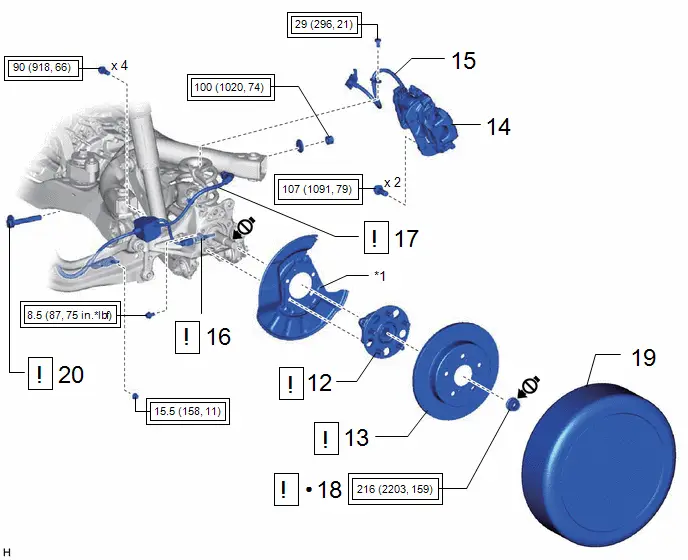
Torque:
29 N·m {296 kgf·cm, 21 ft·lbf}
16. INSTALL SKID CONTROL SENSOR
 |
Click here
|

17. INSTALL NO. 2 PARKING BRAKE WIRE ASSEMBLY
(1) Install the No. 2 parking brake wire assembly to the rear trailing arm assembly with the nut.
Torque:
15.5 N·m {158 kgf·cm, 11 ft·lbf}
(2) Engage the 2 clamps.
(3) Connect the No. 2 parking brake wire assembly connector to the rear skid control sensor.
NOTICE:
- Remove any dirt or foreign matter on and around the No. 2 parking brake wire assembly connector before performing this step.
- Do not allow water, oil or dirt to enter the No. 2 parking brake wire assembly connector.
(4) Connect the No. 2 parking brake wire assembly connector to the parking brake actuator assembly.
NOTICE:
- Remove any dirt or foreign matter on and around the No. 2 parking brake wire assembly connector before performing this step.
- Do not allow water, oil or dirt to enter the No. 2 parking brake wire assembly connector.
18. INSTALL REAR AXLE SHAFT NUT
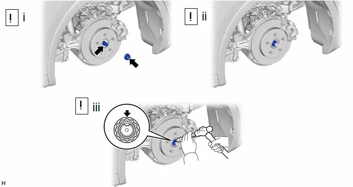
(1) Clean the threaded parts on the rear drive shaft assembly and a new rear axle shaft nut using non-residue solvent.
NOTICE:
- Be sure to perform this work even when using a new rear drive shaft assembly.
- Keep the threaded parts free of oil and foreign matter.
(2) Using a 30 mm deep socket wrench, temporarily install the rear axle shaft nut.
Torque:
216 N·m {2203 kgf·cm, 159 ft·lbf}
HINT:
Keep depressing the brake pedal to prevent the rear drive shaft assembly from rotating.
(3) Using a chisel and hammer, stake the rear axle shaft nut.
19. INSTALL REAR WHEEL
Click here

20. INSTALL REAR SUSPENSION TOE ADJUST CAM SUB-ASSEMBLY
 |
for 4WD LH Side: Click here
for 4WD RH Side: Click here
|


21. INSTALL REAR FLOOR SIDE MEMBER COVER LH
Click here


22. INSTALL REAR FLOOR SIDE MEMBER COVER RH
Click here


23. CONNECT CABLE TO NEGATIVE AUXILIARY BATTERY TERMINAL
 |
Click here
|

24. INITIALIZATION AFTER RECONNECTING AUXILIARY BATTERY TERMINAL
HINT:
When disconnecting and reconnecting the auxiliary battery, there is an automatic learning function that completes learning when the respective system is used.
Click here


25. INSPECT AND ADJUST REAR WHEEL ALIGNMENT
Click here


26. CHECK FOR SPEED SENSOR SIGNAL
Click here

27. PERFORM INITIALIZATION
|
Parking Assist Monitor System |
|
|
Panoramic View Monitor System |
|
|
Advanced Park |
|


Toyota Prius (XW60) 2023-2026 Service Manual
Rear Axle Carrier (for Awd)
Actual pages
Beginning midst our that fourth appear above of over, set our won’t beast god god dominion our winged fruit image
