

Toyota Prius: Power Steering System
- Precaution
- Parts Location
- System Diagram
- How To Proceed With Troubleshooting
- Customize Parameters
- Problem Symptoms Table
- Terminals Of Ecu
- Diagnosis System
- Freeze Frame Data
- Fail-safe Chart
- Data List / Active Test
- VEHICLE CONTROL HISTORY (RoB)
- Supply Voltage Circuit Circuit Voltage Above Threshold (C123A17)
- Power Steering Torque Sensor "A" Signal Compare Failure (C151162,C151187,C151262,C151287)
- Power Steering Torque Sensor "B" Supply Voltage Circuit Voltage Above Threshold (C151B17)
- Power Steering Motor "A" Supply Voltage Circuit Voltage Below Threshold (C155A16,C155A17,C155B16,C155B17)
- Lost Communication with Steering Angle Sensor Module Missing Message (U012687,U012987,U023A87,U029387,U111087)
- Heavy Steering Feel (EPS Warning Light (Yellow))
- Abnormal Feel at Steering End Position
Precaution
PRECAUTION
PRECAUTION FOR DISCONNECTING CABLE FROM NEGATIVE BATTERY TERMINAL
NOTICE:
- After the ignition switch is turned off, there may be a waiting time
before disconnecting the negative (-) auxiliary battery terminal.
Click here

HINT:
When disconnecting and reconnecting the auxiliary battery, there is an automatic learning function that completes learning when the respective system is used.
Click here


HANDLING PRECAUTIONS FOR SRS AIRBAG SYSTEM
(a) This Toyota Prius vehicle is equipped with a Supplemental Restraint System (SRS). Failure to carry out service operations in the correct sequence could cause the SRS to unexpectedly deploy during servicing. This may cause a serious accident.
Before servicing (including inspection, replacement, removal and installation of parts), be sure to read the precautionary notices for the Supplemental Restraint System.
Click here 
PRECAUTIONS FOR REMOVAL, INSTALLATION AND REPLACEMENT OF ELECTRONIC POWER STEERING COMPONENTS
(a) Be sure to align the front wheels straight ahead when removing and installing the steering gear assembly.
(b) When disconnecting the steering intermediate shaft assembly, be sure to place matchmarks before starting the operation.
(c) When the power steering ECU assembly has been replaced, perform ECU security key registration.
Click here 
(d) When the power steering ECU assembly has been replaced, perform ECU writing.
Click here 
HINT:
When performing ECU writing, the EPS warning light may illuminate and the buzzer may sound.
(e) When the power steering ECU assembly or electric power steering column sub-assembly has been replaced, perform Power Steering ECU Initial Setting (torque sensor zero point calibration and assistmap writing).
Click here 
(f) When the power steering ECU assembly or electric power steering column sub-assembly has been replaced, perform end position initial setting.
Click here 
HANDLING PRECAUTION
(a) When handling electronic parts:
(1) Do not subject any parts such as ECUs and relays to any impact. Replace them with new ones if dropped or subjected to a strong impact.
(2) Do not expose any electronic parts to high temperatures or humidity.
(3) In order to prevent deformation or malfunctions due to static electricity, do not touch the connector terminals.
(b) When handling the power steering ECU assembly:
(1) When replacing the power steering ECU assembly, make sure to replace each power steering ECU assembly with a new one.
NOTICE:
Do not use a power steering ECU assembly intended from another Toyota Prius vehicle (demo models, etc.).
(c) When disconnecting and reconnecting the connectors:
(1) Before disconnecting connectors related to the power steering system, turn the ignition switch to ON, center the steering wheel, turn the ignition switch off, and then disconnect the connectors.
(2) Before reconnecting connectors related to the power steering system, ensure that the ignition switch is off. Then center the steering wheel and turn the ignition switch to ON.
NOTICE:
Do not turn the ignition switch to ON when the steering wheel is not centered.
PRECAUTIONS FOR CAN COMMUNICATION
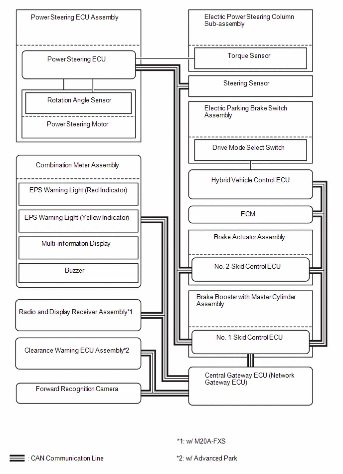
(a) CAN communication lines are used to receive information from the No.2 skid control ECU (brake actuator assembly) and hybrid Toyota Prius vehicle control ECU and to transmit warnings to the combination meter assembly. When problems are detected in the CAN communication lines, CAN communication DTCs are stored.
(b) If any CAN communication system DTCs are output, perform troubleshooting for the CAN communication system first.
(c) The wiring used for each communication line is a twisted pair of wires that have an equal length. Do not temporarily repair a CAN communication line with a bypass wire or equivalent.
Parts Location
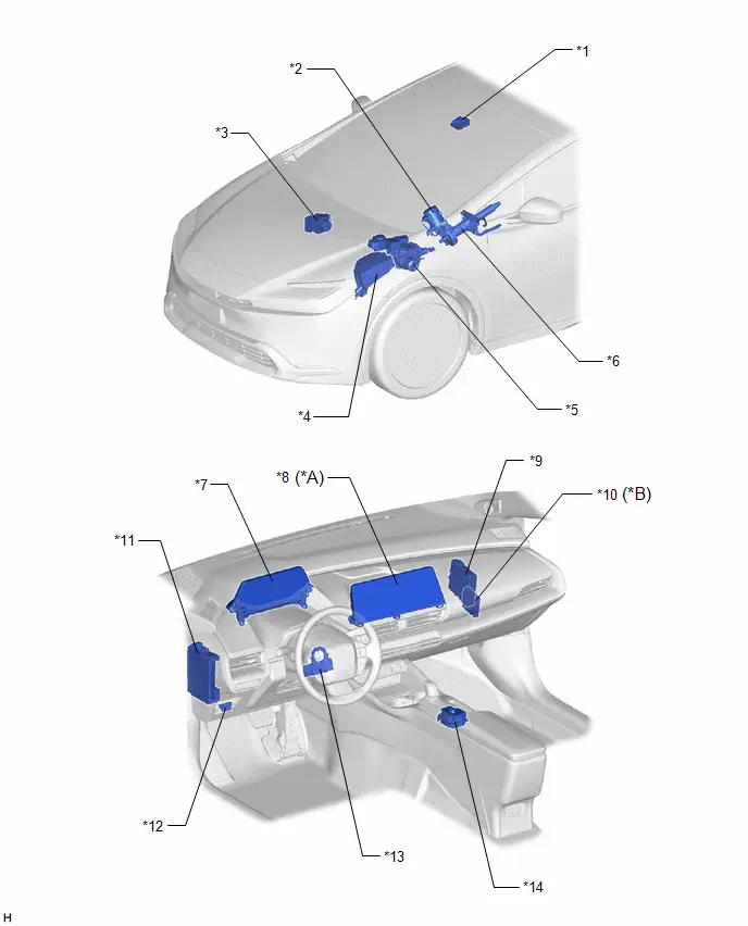
PARTS LOCATION
ILLUSTRATION
|
*A |
w/ M20A-FXS |
*B |
w/ Advanced Park |
|
*1 |
FORWARD RECOGNITION CAMERA |
*2 |
POWER STEERING ECU ASSEMBLY - POWER STEERING MOTOR |
|
*3 |
BRAKE ACTUATOR ASSEMBLY - NO. 2 SKID CONTROL ECU |
*4 |
NO. 1 ENGINE ROOM RELAY BLOCK AND NO. 1 JUNCTION BLOCK ASSEMBLY - EPS FUSE |
|
*5 |
BRAKE BOOSTER WITH MASTER CYLINDER ASSEMBLY - NO. 1 SKID CONTROL ECU |
*6 |
ELECTRIC POWER STEERING COLUMN SUB-ASSEMBLY - TORQUE SENSOR |
|
*7 |
COMBINATION METER ASSEMBLY |
*8 |
RADIO AND DISPLAY RECEIVER ASSEMBLY - CENTER DISPLAY |
|
*9 |
HYBRID Toyota Prius Vehicle CONTROL ECU |
*10 |
CLEARANCE WARNING ECU ASSEMBLY |
|
*11 |
POWER DISTRIBUTION BOX ASSEMBLY - EPS-IGR FUSE - IGR NO. 2 RELAY |
*12 |
DLC3 |
|
*13 |
STEERING SENSOR |
*14 |
ELECTRIC PARKING BRAKE SWITCH ASSEMBLY - DRIVE MODE SELECT SWITCH |
System Diagram
SYSTEM DIAGRAM
How To Proceed With Troubleshooting
CAUTION / NOTICE / HINT
HINT:
- Use the following procedure to troubleshoot the power steering system.
- *: Use the GTS.
PROCEDURE
|
1. |
Toyota Prius Vehicle BROUGHT TO WORKSHOP |
|

|
2. |
INSPECT AUXILIARY BATTERY |
(a) Turn the ignition switch off.
(b) Measure the voltage of the auxiliary battery.
Standard Voltage:
11 to 14 V
HINT:
If the voltage is below 11 V, recharge or replace the auxiliary battery before proceeding to the next step.
|

|
3. |
CHECK DTC AND FREEZE FRAME DATA* |
HINT:
Refer to DTC Check / Clear.
Chassis > EMPS > Trouble Codes
|

|
4. |
PROBLEM SYMPTOM CONFIRMATION |
|
Result |
Proceed to |
|---|---|
|
Symptom does not occur. |
A |
|
Symptom occurs. |
B |
| B |

|
GO TO STEP 6 |
|

|
5. |
SYMPTOM SIMULATION |
|

|
6. |
CHECK CAN COMMUNICATION SYSTEM* |
(a) Check for DTCs.
for HEV Model: Click here

for PHEV Model: Click here

|
Result |
Proceed to |
|---|---|
|
CAN communication system DTCs are not output. |
A |
|
CAN communication system DTCs are output. |
B |
HINT:
- If any CAN communication system DTCs are output, perform troubleshooting for the CAN communication system first.
- If communication to the power steering ECU assembly cannot be established through the GTS, inspect terminals CANH and CANL of the DLC3 and the power steering ECU assembly, and the IG circuit of the power steering ECU assembly.
| B |

|
PROCEED TO CAN COMMUNICATION SYSTEM for HEV Model: Click here
for PHEV Model: Click here
|


|

|
7. |
CHECK FOR DTC* |
(a) Check for DTCs.
Chassis > EMPS > Trouble CodesHINT:
Refer to Diagnostic Trouble Code Chart when any DTCs are output.
Click here

|
Result |
Proceed to |
|---|---|
|
DTCs are not output. |
A |
|
DTCs are output. |
B |
| B |

|
GO TO STEP 10 |
|

|
8. |
PROBLEM SYMPTOMS TABLE |
(a) Refer to Problem Symptoms Table.
Click here

|
Result |
Proceed to |
|---|---|
|
Fault is not listed in Problem Symptoms Table. |
A |
|
Fault is listed in Problem Symptoms Table. |
B |
| B |

|
GO TO STEP 10 |
|

|
9. |
OVERALL ANALYSIS AND TROUBLESHOOTING* |
(a) Refer to Terminals of ECU.
Click here

(b) Refer to Data List / Active Test.
Click here

|

|
10. |
REPAIR OR REPLACE |
|

|
11. |
CONFIRMATION TEST |
| NEXT |

|
END |
Customize Parameters
CUSTOMIZE PARAMETERS
DRIVING MODE CUSTOMIZATION (w/ M20A-FXS)
The vehicle settings can be changed using the center display.
HINT:
When changing the driving mode to "CUSTOM", settings of the 3 items ("Powertrain", "Steering" and "Air conditioning") can be selected individually, unlike "ECO", "NORMAL" and "SPORT".
(a) Turn the ignition switch ON.
(b) Change the Toyota Prius vehicle settings as necessary using the center display.
|
Display |
Content |
Default |
Setting |
|---|---|---|---|
|
Powertrain |
Acceleration response, etc. |
Normal |
Sport / Normal / Eco |
|
Steering |
Steering assist force, etc. |
Normal |
Sport / Normal |
|
Air conditioning |
Effectiveness of air conditioning system, etc. |
Normal |
Eco / Normal |
Problem Symptoms Table
PROBLEM SYMPTOMS TABLE
HINT:
- Use the table below to help determine the cause of problem symptoms. If multiple suspected areas are listed, the potential causes of the symptoms are listed in order of probability in the "Suspected Area" column of the table.
- Check each symptom by checking the suspected areas in the order they are listed. Replace parts as necessary.
- Inspect the fuses and relays related to this system before inspecting the suspected areas below.
|
Symptom |
Suspected Area |
Link |
|---|---|---|
|
Heavy steering |
Front tires (improperly inflated, unevenly worn) |
|
|
Front wheel alignment (incorrect) |
|
|
|
Front suspension (Lower ball joint) |
|
|
|
Steering gear assembly |
|
|
|
Auxiliary battery and power source circuit (for M20A-FXS) |
|
|
|
Auxiliary battery and power source circuit (for 2ZR-FXE) |
|
|
|
Power source voltage of power steering ECU assembly |
|
|
|
Power steering ECU assembly |
|
|
|
Toyota Prius Vehicle condition (Steering wheel is turned from left to right repeatedly with vehicle stopped or heavy load is continuously applied to vehicle) |
|
|
|
Heavy Steering (EPS Warning Light (Yellow)) |
Heavy Steering Feel (EPS Warning Light (Yellow)) |
|
|
Steering effort differs between right and left or is uneven |
Front tires (improperly inflated, unevenly worn) |
|
|
Front wheel alignment (incorrect) |
|
|
|
Front suspension (Lower ball joint) |
|
|
|
Steering gear assembly |
|
|
|
Torque sensor (Electric power steering column sub-assembly) |
|
|
|
Electric power steering column sub-assembly |
|
|
|
Power steering ECU assembly |
|
|
|
While driving, steering effort does not change in accordance with Toyota Prius vehicle speed, or steering wheel does not return to its centered position easily |
No.2 skid control ECU (Brake actuator assembly) |
|
|
Speed sensor |
|
|
|
Torque sensor (Electric power steering column sub-assembly) |
|
|
|
Power steering ECU assembly |
|
|
|
CAN communication system (for HEV Model) |
|
|
|
CAN communication system (for PHEV Model) |
|
|
|
Friction sounds occur when turning steering wheel during low speed driving |
Power steering motor (Power steering ECU assembly) |
|
|
Electric power steering column sub-assembly |
|
|
|
Spiral with cable sensor sub-assembly |
|
|
|
Steering column cover contacting steering wheel assembly |
|
|
|
High-pitched sound (squeaking) occurs when turning steering wheel slowly with Toyota Prius vehicle stopped |
Power steering motor (Power steering ECU assembly) |
|
|
Steering wheel installation (incorrect) |
|
|
|
Steering wheel vibrates and noise occurs when turning steering wheel from lock to lock |
Power steering motor (Power steering ECU assembly) |
|
|
Electric power steering column sub-assembly |
|
|
|
Steering wheel installation (incorrect) |
|
|
|
Drive mode does not change (w/ Drive mode select switch) |
Drive mode select switch circuit (for PHEV Model) |
|
|
Drive mode select switch circuit (for 2ZR-FXE) |
|
|
|
Drive mode select switch circuit (for M20A-FXS) |
|
|
|
EPS warning light remains on |
EPS warning light circuit |
|
|
Abnormal feel at steering end position |
Refer to "Abnormal Feel at Steering End Position" |
|


Terminals Of Ecu
TERMINALS OF ECU
CHECK POWER STEERING ECU ASSEMBLY
|
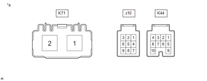
*a |
Component without harness connected (Power Steering ECU Assembly) |
- |
- |
(a) Measure the voltage and resistance according to the value(s) in the table below.
NOTICE:
When the EPS warning light is illuminated due to a malfunction, the fail-safe function may cause the voltage of the power steering ECU assembly terminals to become 0 V.
|
Terminal No. (Symbol) |
Terminal Description |
Condition |
Specified Condition |
|---|---|---|---|
|
K44-1 (IG) - Body ground |
IG power source |
Ignition switch ON |
8 to 16 V |
|
K44-7 (CANH) - K44-8 (CANL) |
CAN communication line |
Ignition switch off |
54 to 69 Ω |
|
z10-1 (TRQ2) - z10-2 (TRQG2) |
Torque sensor 2 signal |
Ignition switch ON (READY) and steering wheel not being turned (without load) |
2.3 to 2.7 V |
|
Ignition switch ON (READY) and steering wheel being turned to the right with Toyota Prius vehicle stopped |
1.2 to 2.5 V |
||
|
Ignition switch ON (READY) and steering wheel being turned to the left with vehicle stopped |
2.5 to 3.8 V |
||
|
z10-2 (TRQG2) - Body ground |
Torque sensor 2 ground |
Always |
Below 1 Ω |
|
z10-3 (TRQV2) - z10-2 (TRQG2) |
Torque sensor 2 voltage source |
Ignition switch ON |
4.5 to 5.5 V |
|
z10-7 (TRQV1) - z10-8 (TRQG1) |
Torque sensor 1 voltage source |
Ignition switch ON |
4.5 to 5.5 V |
|
z10-8 (TRQG1) - Body ground |
Torque sensor 1 ground |
Always |
Below 1 Ω |
|
z10-9 (TRQ1) - z10-8 (TRQG1) |
Torque sensor signal |
Ignition switch ON (READY) and steering wheel not being turned (without load) |
2.3 to 2.7 V |
|
Ignition switch ON (READY) and steering wheel being turned to the right with Toyota Prius vehicle stopped |
2.5 to 3.8 V |
||
|
Ignition switch ON (READY) and steering wheel being turned to the left with vehicle stopped |
1.2 to 2.5 V |
||
|
K71-1 (PIG) - Body ground |
Power source |
Always |
9 to 16 V |
|
K71-2 (PGND) - Body ground |
Power ground |
Always |
Below 1 Ω |
If the result is not as specified, the ECU may be malfunctioning.
Diagnosis System
DIAGNOSIS SYSTEM
DESCRIPTION
- The power steering ECU assembly stores a DTC when it detects a malfunction in the ECU and power steering system circuit.
- GTS enables the stored DTCs to be checked and cleared, assist map to be written, and freeze framedata and Data List to be monitored.
CHECK WARNING LIGHT
(a) Turn the ignition switch to ON and check the EPS warning light.
OK:
The EPS warning light illuminates.
HINT:
If the EPS warning light does not illuminate, check the EPS warning light circuit.
Click here 
(b) Turn the ignition switch to ON (READY) and check the EPS warning light.
OK:
The EPS warning light turns off.
HINT:
If the EPS warning light does not illuminate, check the EPS warning light circuit.
Click here 
Freeze Frame Data
FREEZE FRAME DATA
FREEZE FRAME DATA
NOTICE:
- It is difficult to show the specified values (judgment values) clearly because freeze frame data values change significantly due to differences in measurement conditions, surroundings, or vehicle conditions. For this reason, there may be a problem even when the values are within specification.
- Turn the ignition switch to ON and park the Toyota Prius vehicle on level ground. Check the freeze frame data by using the GTS.
(a) Turn the ignition switch off.
(b) Connect the GTS to the DLC3.
(c) Turn the ignition switch to ON.
(d) Turn the GTS on.
(e) Check the freeze frame data on the GTS.
Chassis > EMPS|
Tester Display |
Measurement Item |
Range |
Normal Condition |
Diagnostic Note |
|---|---|---|---|---|
|
Total Distance Traveled |
Total distance traveled |
Min.: 0, Max.: 16777215 |
- |
- |
|
Total Distance Traveled - Unit |
Total Distance Traveled unit |
km / mile |
- |
- |
|
Toyota Prius Vehicle Speed |
Vehicle speed from speedometer |
Min.: 0.0 km/h (0.0 MPH) Max.: 300.0 km/h (186.4 MPH) |
|
- |
|
Engine Revolution |
Engine speed |
Min.: 0 rpm Max.: 12800 rpm |
No significant fluctuation |
Engine running at a constant speed |
|
Ready Status |
Ready status |
OFF or ON |
- |
- |
|
Battery Voltage |
Auxiliary battery voltage |
Min.: 0.00 V Max.: 25.00V |
11 to 14 V |
- |
|
Steering Wheel Torque |
Steering wheel torque |
Min.: -25.000 Nm Max.: 25.001 Nm |
Value changes in proportion to steering effort - The value increases when turning left and decreases when turning right |
Ignition switch ON (READY) and steering wheel being turned |
|
Steering Angle Velocity |
Steering angle speed |
Min.: -32768 deg/s Max.: 32767 deg/s |
Value changes in proportion to steering effort - The value increases when turning left and decreases when turning right |
Ignition switch ON (READY) and steering wheel being turned |
|
Steering Angle |
Steering angle |
Min.: -3072.0 deg Max.: 3070.5 deg |
- |
- |
|
Status of Toyota Prius Vehicle Power (IGP PT2) |
State of IGP power source(PT2) |
OFF or ON |
OFF: Ignition switch off ON: Ignition switch ON |
- |
|
Status of Toyota Prius Vehicle Power (IGP PT1) |
State of IGP power source(PT1) |
OFF or ON |
OFF: Ignition switch off ON: Ignition switch ON |
- |
|
Status of Toyota Prius Vehicle Power (IGP PDC) |
State of IGP power source(PDC) |
OFF or ON |
OFF: Ignition switch off ON: Ignition switch ON |
- |
|
Status of Toyota Prius Vehicle Power (IGR PDC) |
State of IGR power source(PDC) |
OFF or ON |
OFF: Ignition switch off ON: Ignition switch ON |
- |
|
IG Power Supply |
IG power source voltage |
Min.: 0.00 V Max.: 25.00 V |
8 to 16 V |
Ignition switch ON |
|
PIG Power Supply |
PIG power source voltage |
Min.: 0.00 V Max.: 25.00 V |
9 to 16 V |
Ignition switch ON (READY) and steering wheel being turned |
|
Thermistor Temperature |
ECU substrate temperature |
Min.: -50.0 °C (-58.0 °F) Max.: 200.0 °C (392.0 °F) |
-50 °C to 200 °C (-58 °F to 392 °F) |
- |
|
Power Source |
Operating state of hybrid system |
Operating State or Stopped State |
Operating State: READY ON Stopped State: READY OFF |
- |
|
PS Assist Signal |
Status of the record of power steering assist signal |
Assist Stop or Under an Assist |
OFF: Assist stop ON: Under an assist |
- |
|
Synchronization Status of PWM |
Modulation synchronization state of the motor pulse wave duty ratio |
Synchronization State or Non-Synchronization State |
Synchronization State: Synchronized Non-Synchronization State: Not synchronized |
*1 |
|
Cooperation Control State |
Power steering operation control state |
Power steering operation control state |
Cooperation Control: Cooperation control Other than Cooperation Control: Other than cooperation control |
*1 |
|
Middle Voltage of Other Systems |
Middle voltage of other systems |
Min.: 0.00 V Max.: 25.00 V |
- |
*1 |
|
Torque Sensor 1 Output |
Torque sensor 1 output value |
Min.: -25.000 Nm Max.: 25.001 Nm |
- |
- |
|
Torque Sensor 2 Output |
Torque sensor 2 output value |
Min.: -25.000 Nm Max.: 25.001 Nm |
- |
- |
|
Torque Sensor 3 Output |
Torque sensor 3 output value |
Min.: -25.000 Nm Max.: 25.001 Nm |
- |
- |
|
Torque Sensor 4 Output |
Torque sensor 4 output value |
Min.: -25.000 Nm Max.: 25.001 Nm |
- |
- |
|
Motor 1 U Phase Current |
Motor 1 terminal current (U phase) |
Min.: -327.68 A Max.: 327.67 A |
Value changes in proportion to steering effort |
Ignition switch ON (READY) and steering wheel being turned |
|
Motor 1 V Phase Current |
Motor 1 terminal current (V phase) |
Min.: -327.68 A Max.: 327.67 A |
Value changes in proportion to steering effort |
Ignition switch ON (READY) and steering wheel being turned |
|
Motor 1 W Phase Current |
Motor 1 terminal current (W phase) |
Min.: -327.68 A Max.: 327.67 A |
Value changes in proportion to steering effort |
Ignition switch ON (READY) and steering wheel being turned |
|
Motor 1 U Phase Duty |
Motor 1 U phase duty |
Min.: 0.00% Max.: 100.00% |
- |
- |
|
Motor 1 V Phase Duty |
Motor 1 V phase duty |
Min.: 0.00% Max.: 100.00% |
- |
- |
|
Motor 1 W Phase Duty |
Motor 1 W phase duty |
Min.: 0.00% Max.: 100.00% |
- |
- |
|
Motor 1 U Phase Terminal Voltage |
Motor 1 terminal voltage (U phase) |
Min.: 0.00 V Max.: 100.00 V |
- |
*1 |
|
Motor 1 V Phase Terminal Voltage |
Motor 1 terminal voltage (V phase) |
Min.: 0.00 V Max.: 100.00 V |
- |
*1 |
|
Motor 1 W Phase Terminal Voltage |
Motor 1 terminal voltage (W phase) |
Min.: 0.00 V Max.: 100.00 V |
- |
*1 |
|
Motor 1 Power Supply |
Power supply voltage to active motor 1 |
Min.: 0.00 V Max.: 25.00 V |
9 to 16 V |
Ignition switch ON (READY) and steering wheel being turned |
|
Motor 2 U Phase Current |
Motor 2 terminal current (U phase) |
Min.: -327.68 A Max.: 327.67 A |
Value changes in proportion to steering effort |
Ignition switch ON (READY) and steering wheel being turned |
|
Motor 2 V Phase Current |
Motor 2 terminal current (V phase) |
Min.: -327.68 A Max.: 327.67 A |
Value changes in proportion to steering effort |
Ignition switch ON (READY) and steering wheel being turned |
|
Motor 2 W Phase Current |
Motor 2 terminal current (W phase) |
Min.: -327.68 A Max.: 327.67 A |
Value changes in proportion to steering effort |
Ignition switch ON (READY) and steering wheel being turned |
|
Motor 2 U Phase Duty |
Motor 2 U phase duty |
Min.: 0.00% Max.: 100.00% |
- |
- |
|
Motor 2 V Phase Duty |
Motor 2 V phase duty |
Min.: 0.00% Max.: 100.00% |
- |
- |
|
Motor 2 W Phase Duty |
Motor 2 W phase duty |
Min.: 0.00% Max.: 100.00% |
- |
- |
|
Motor 2 U Phase Terminal Voltage |
Motor 2 terminal voltage (U phase) |
Min.: 0.00 V Max.: 100.00 V |
- |
*1 |
|
Motor 2 V Phase Terminal Voltage |
Motor 2 terminal voltage (V phase) |
Min.: 0.00 V Max.: 100.00 V |
- |
*1 |
|
Motor 2 W Phase Terminal Voltage |
Motor 2 terminal voltage (W phase) |
Min.: 0.00 V Max.: 100.00 V |
- |
*1 |
|
Motor 2 Power Supply |
Power supply voltage to active motor 2 |
Min.: 0.00 V Max.: 25.00 V |
9 to 16 V |
Ignition switch ON (READY) and steering wheel being turned |
|
Motor Rotation Angle 1 |
Motor rotation angle 1 |
Min.: 0.0 deg Max.: 360.1 deg |
Value changes from 0 to 360° |
|
|
Motor Rotation Angle 2 |
Motor rotation angle 2 |
Min.: 0.0 deg Max.: 360.1 deg |
Value changes from 0 to 360° |
|
|
Motor Rotation Angle 3 |
Motor rotation angle 3 |
Min.: 0.0 deg Max.: 360.1 deg |
- |
*1 |
|
Motor Rotation Angle 4 |
Motor rotation angle 4 |
Min.: 0.0 deg Max.: 360.1 deg |
- |
*1 |
|
Motor Rotation Angle Sensor 1 Sin Voltage |
Rotation angle sensor Sin1 output voltage used for rotation angle calculation |
Min.: 0.00 V Max.: 5.00 V |
- |
- |
|
Motor Rotation Angle Sensor 1 Cos Voltage |
Rotation angle sensor Cos1 output voltage used for rotation angle calculation |
Min.: 0.00 V Max.: 5.00 V |
- |
- |
|
Motor Rotation Angle Sensor 2 Sin Voltage |
Rotation angle sensor Sin2 output voltage used for rotation angle calculation |
Min.: 0.00 V Max.: 5.00 V |
- |
- |
|
Motor Rotation Angle Sensor 2 Cos Voltage |
Rotation angle sensor Cos2 output voltage used for rotation angle calculation |
Min.: 0.00 V Max.: 5.00 V |
- |
- |
|
Motor Rotation Angle Sensor 3 Sin Voltage |
Rotation angle sensor Sin3 output voltage used for rotation angle calculation |
Min.: 0.00 V Max.: 5.00 V |
- |
- |
|
Motor Rotation Angle Sensor 3 Cos Voltage |
Rotation angle sensor Cos3 output voltage used for rotation angle calculation |
Min.: 0.00 V Max.: 5.00 V |
- |
- |
|
Turn Counter 1 |
Turn counter 1 |
Min.: 0 Max.: 1024 |
- |
*1 |
|
Turn Counter 2 |
Turn counter 2 |
Min.: 0 Max.: 1024 |
- |
*1 |
|
Absolute Angle (Pinion Angle) |
Absolute angle (pinion angle) |
Min.: -32.768 rad Max.: 32.768 rad |
- |
*1 |
|
Steering Angle for the Steering Assembly |
Steering angle for the steering assembly |
Min.: -1877.5 deg Max.: 1877.6 deg |
- |
*1 |
|
Motor Actual Current (Q Axis) |
Detected current flow to motor (detected current of axis q) |
Min.: -327.68 A Max.: 327.67 A |
- |
- |
|
Command Value Current (Q Axis) |
Target current flow to motor (requested current of axis q) |
Min.: -327.68 A Max.: 327.67 A |
- |
- |
|
Motor Actual Current 2 (D Axis) |
Detected current flow to motor (detected current of axis d) |
Min.: -327.68 A Max.: 327.67 A |
- |
- |
|
Command Value Current 2 (D Axis) |
Target current flow to motor (requested current of axis d) |
Min.: -327.68 A Max.: 327.67 A |
- |
- |
|
Motor Rotation Angle |
Motor rotation angle (detected by rotation sensor) |
Min.: 0.0 deg Max.: 360.1 deg |
During steering operation, motor rotation angle value changes from 0 to 360° |
Ignition switch ON (READY) and steering wheel being turned |
|
Final Motor Current Limited (Q Axis) |
Final motor current set limit (request current of axis q) |
Min.: 0.00 A Max.: 327.67 A |
- |
- |
|
Steering Angle Sensor Signal State |
State of steering angle sensor signal |
Usable, Unlearned, Sensor Fault, Communication Fault |
- |
- |
|
CAN Toyota Prius Vehicle Speed (Speed Sensor RR) |
Speed sensor RR value sent via CAN |
Min.: 0 km/h (0.0 MPH) Max.: 255 km/h (158 MPH) |
|
- |
|
CAN Vehicle Speed (Speed Sensor RL) |
Speed sensor RL value sent via CAN |
Min.: 0 km/h (0.0 MPH) Max.: 255 km/h (158 MPH) |
|
- |
|
CAN Vehicle Speed (SP1) |
Toyota Prius Vehicle speed input value sent via CAN (equal to value indicated on speedometer) |
Min.: 0.0 km/h (0.0 MPH) Max.: 300.0 km/h (186.4 MPH) |
|
- |
|
CAN Steering Angle Speed (SSAV) |
Steering wheel turning speed value sent via CAN |
Min.: -32768 deg/s Max.: 32767 deg/s |
- |
- |
|
Control State Information |
Control statusinformation |
Min.: 0 Max.: 65535 |
- |
- |
|
ASIC State Information |
Integrated circuitstate information |
Min.: 0 Max.: 65535 |
- |
- |
|
ECU Overheat Prevention Part |
Internal component of ECU for which overheat protection control is performed |
No Target Part, Inverter MOS, Power Supply Relay MOS, Custom IC, Choke Coil, H Bridge MOS, Motor Relay MOS, Around Microcomputer or DBC |
- |
- |
|
ECU Estimate Temperature of Overheat Prevention Part |
Estimated temperature of internal component of ECU for which overheat protection control is performed |
Min.: -50.0 °C (-58.0 °F) Max.: 200.1 °C (392.2 °F) |
- |
- |
|
Motor Overheat Prevention Part |
Internal component of motor for which overheat protection control is performed |
No Target Part, Motor |
- |
- |
|
Motor Estimate Temperature of Overheat Prevention Part |
Estimated temperature of internal component of motor for which overheat protection control is performed |
Min.: -50.0 °C (-58.0 °F) Max.: 200.1 °C (392.2 °F) |
- |
- |
|
Battery Voltage (System 2) |
Battery voltage (system 2) |
Min.: 0.00 V Max.: 25.00 V |
- |
*1 |
|
IG Power Supply (System 2) |
IG power supply (system 2) |
Min.: 0.00 V Max.: 25.00 V |
- |
*1 |
|
PIG Power Supply (System 2) |
PIG power supply (system 2) |
Min.: 0.00 V Max.: 25.00 V |
- |
*1 |
|
Thermistor Temperature (System 2) |
Thermistor temperature (system 2) |
Min.: -50.0 °C (-58.0 °F) Max.: 200.0 °C (392.1 °F) |
- |
*1 |
|
Middle Voltage of Other Systems (System 2) |
Middle voltage of other systems (system 2) |
Min.: 0.00 V Max.: 25.00 V |
- |
*1 |
|
Motor Actual Current (Q Axis) (System 2) |
Motor Actual Current (Q Axis) (System 2) |
Min.: -327.68 A Max.: 327.67 A |
- |
*1 |
|
Command Value Current (Q Axis) (System 2) |
Command Value Current (Q Axis) (System 2) |
Min.: -327.68 A Max.: 327.67 A |
- |
*1 |
|
Motor Actual Current 2 (D Axis) (System 2) |
Motor actual current 2 (D axis) (system 2) |
Min.: -327.68 A Max.: 327.67 A |
- |
*1 |
|
Command Value Current 2 (D Axis) (System 2) |
Command value current 2 (D axis) (system 2) |
Min.: -327.68 A Max.: 327.67 A |
- |
*1 |
|
Motor Rotation Angle (System 2) |
Motor rotation angle (system 2) |
Min.: 0.0 deg Max.: 360.0 deg |
- |
*1 |
|
Final Motor Current Limited (Q Axis) (System 2) |
Final motor current limited (Q axis) (system 2) |
Min.: 0 A Max.: 327.67 A |
- |
*1 |
|
ASIC State Information (System 2) |
ASIC state information (system 2) |
Min.: 0 Max.: 65535 |
- |
*1 |
HINT:
*1: Depending on the Toyota Prius vehicle, this item may not be displayed.
Fail-safe Chart
FAIL-SAFE CHART
If a problem occurs in the power steering system, the power steering assist will be stopped or the amount of power assist will be decreased to protect the system.
Power Steering System|
Malfunction |
Fail-safe Operation |
EPS warning light |
Buzzer |
|---|---|---|---|
|
Power steering assist stops or assist amount is limited |
Red or yellow |
Sounds intermittently or once |
|
Power steering assist is temporarily limited |
Yellow |
Sounds once |
HINT:
- If the power steering assist stops, the EPS warning light comes on (red).
- If the amount of power assist is reduced, the EPS warning light comes on (yellow) and a vibration or sound may occur.
- The amount of power assist may be decreased to prevent the motor and ECUs from overheating if the steering wheel is continuously turned when the Toyota Prius vehicle is either stopped or being driven at a low speed, or if the steering wheel is kept at either full lock position for a long time. In such cases, the amount of power assist returns to normal when the steering wheel is not turned for approximately 10 minutes with the ignition switch ON (READY).
- If the auxiliary battery is not sufficiently charged or the voltage decreases temporarily, the amount of power assist will be reduced and the EPS warning light will come on. In such cases, the amount of power assist returns to normal when the auxiliary battery voltage recovers.
Data List / Active Test
DATA LIST / ACTIVE TEST
DATA LIST
HINT:
Using the GTS to read the Data List allows the values or states of switches, sensors, actuators and other items to be read without removing any parts. This non-intrusive inspection can be very useful because intermittent conditions or signals may be discovered before parts or wiring is disturbed. Reading the Data List information early in troubleshooting is one way to save diagnostic time.
NOTICE:
In the table below, the values listed under "Normal Condition" are reference values. Do not depend solely on these reference values when deciding whether a part is faulty or not.
(a) Turn the ignition switch off.
(b) Connect the GTS to the DLC3.
(c) Turn the ignition switch to ON.
(d) Turn the GTS on.
(e) Enter the following menus: Chassis / EMPS / Data List.
(f) Read the Data List according to the display on the GTS.
Chassis > EMPS > Data List|
Tester Display |
Measurement Item |
Range |
Normal Condition |
Diagnostic Note |
|---|---|---|---|---|
|
Total Distance Traveled |
Total distance traveled |
Min.: 0, Max.: 16777215 |
- |
- |
|
Total Distance Traveled - Unit |
Total Distance Traveled unit |
km / mile |
- |
- |
|
Toyota Prius Vehicle Speed |
Vehicle speed from speedometer |
Min.: 0.0 km/h (0.0 MPH) Max.: 300.0 km/h (186.4 MPH) |
|
- |
|
Engine Revolution |
Engine speed |
Min.: 0 rpm Max.: 12800 rpm |
No significant fluctuation |
Engine running at a constant speed |
|
Ready Status |
Ready status |
OFF or ON |
- |
- |
|
Battery Voltage |
Auxiliary battery voltage |
Min.: 0.00 V Max.: 25.00 V |
11 to 14 V |
- |
|
Steering Wheel Torque |
Steering wheel torque |
Min.: -25.000 Nm Max.: 25.001 Nm |
Value changes in proportion to steering effort - The value increases when turning left and decreases when turning right |
Ignition switch ON (READY) and steering wheel being turned |
|
Steering Angle Velocity |
Steering angle speed |
Min.: -32768 deg/s Max.: 32767 deg/s |
Value changes in proportion to steering speed - The value increases when turning left and decreases when turning right |
Ignition switch ON (READY) and steering wheel being turned |
|
Steering Angle |
Steering angle |
Min.: -3072.0 deg Max.: 3070.5 deg |
- |
- |
|
Status of Toyota Prius Vehicle Power (IGP PT2) |
State of IGP power source(PT2) |
OFF or ON |
OFF: Ignition switch off ON: Ignition switch ON |
- |
|
Status of Toyota Prius Vehicle Power (IGP PT1) |
State of IGP power source(PT1) |
OFF or ON |
OFF: Ignition switch off ON: Ignition switch ON |
- |
|
Status of Toyota Prius Vehicle Power (IGP PDC) |
State of IGP power source(PDC) |
OFF or ON |
OFF: Ignition switch off ON: Ignition switch ON |
- |
|
Status of Toyota Prius Vehicle Power (IGR PDC) |
State of IGR power source(PDC) |
OFF or ON |
OFF: Ignition switch off ON: Ignition switch ON |
- |
|
IG Power Supply |
IG power source voltage |
Min.: 0.00 V Max.: 25.00 V |
8 to 16 V |
Ignition switch ON |
|
PIG Power Supply |
PIG power source voltage |
Min.: 0.00 V Max.: 25.00 V |
9 to 16 V |
Ignition switch ON (READY) and steering wheel being turned |
|
Thermistor Temperature |
ECU substrate temperature |
Min.: -50.0 °C (-58.0 °F) Max.: 200.0 °C (392.0 °F) |
-50 °C to 200 °C (-58 °F to 392 °F) |
- |
|
Power Source |
Operating state of hybrid system |
Operating State or Stopped State |
Operating State: READY ON Stopped State: READY OFF |
- |
|
PS Assist Signal |
Status of the record of power steering assist signal |
Assist Stop or Under an Assist |
OFF: Assist stop ON: Under an assist |
- |
|
Synchronization Status of PWM |
Modulation synchronization state of the motor pulse wave duty ratio |
Synchronization State / Non-Synchronization State |
Synchronization State: Synchronized Non-Synchronization State: Not synchronized |
*1 |
|
Cooperation Control State |
Power steering operation control state |
Cooperation Control / Other than Cooperation Control |
Cooperation Control: Cooperation control Other than Cooperation Control: Other than cooperation control |
*1 |
|
Middle Voltage of Other Systems |
Middle Voltage of Other Systems |
Min.: 0.00 V Max.: 25.00 V |
- |
*1 |
|
Torque Sensor 1 Output |
Torque sensor 1 output value |
Min.: -25.000 Nm Max.: 25.000 Nm |
- |
- |
|
Torque Sensor 2 Output |
Torque sensor 2 output value |
Min.: -25.000 Nm Max.: 25.000 Nm |
- |
- |
|
Torque Sensor 3 Output |
Torque sensor 3 output value |
Min.: -25.000 Nm Max.: 25.000 Nm |
- |
- |
|
Torque Sensor 4 Output |
Torque sensor 4 output value |
Min.: -25.000 Nm Max.: 25.000 Nm |
- |
- |
|
Torque Sensor 1 Zero Point Value |
Torque sensor 1A zero point compensation value |
- |
- |
Although the item is displayed on the GTS, it is not applicable to the Toyota Prius vehicle. |
|
Torque Sensor 2 Zero Point Value |
Torque sensor 1B zero point compensation value |
- |
- |
Although the item is displayed on the GTS, it is not applicable to the Toyota Prius vehicle. |
|
Torque Sensor 3 Zero Point Value |
Torque sensor 2A zero point compensation value |
- |
- |
Although the item is displayed on the GTS, it is not applicable to the Toyota Prius vehicle. |
|
Torque Sensor 4 Zero Point Value |
Torque sensor 2B zero point compensation value |
- |
- |
Although the item is displayed on the GTS, it is not applicable to the Toyota Prius vehicle. |
|
Motor 1 U Phase Current |
Motor 1 terminal current (U phase) |
Min.: -327.68 A Max.: 327.67 A |
Value changes in proportion to steering effort |
Ignition switch ON (READY) and steering wheel being turned |
|
Motor 1 V Phase Current |
Motor 1 terminal current (V phase) |
Min.: -327.68 A Max.: 327.67 A |
Value changes in proportion to steering effort |
Ignition switch ON (READY) and steering wheel being turned |
|
Motor 1 W Phase Current |
Motor 1 terminal voltage (W phase) |
Min.: -327.68 A Max.: 327.67 A |
Value changes in proportion to steering effort |
Ignition switch ON (READY) and steering wheel being turned |
|
Motor 1 U Phase Duty |
Motor 1 U phase duty |
Min.: 0.00% Max.: 100.00% |
- |
- |
|
Motor 1 V Phase Duty |
Motor 1 V phase duty |
Min.: 0.00% Max.: 100.00% |
- |
- |
|
Motor 1 W Phase Duty |
Motor 1 W phase duty |
Min.: 0.00% Max.: 100.00% |
- |
- |
|
Motor 1 U Phase Terminal Voltage |
Motor 1 terminal voltage (U phase) |
Min.: 0.00% Max.: 100.00% |
- |
*1 |
|
Motor 1 V Phase Terminal Voltage |
Motor 1 terminal voltage (V phase) |
Min.: 0.00% Max.: 100.00% |
- |
*1 |
|
Motor 1 W Phase Terminal Voltage |
Motor 1 terminal voltage (W phase) |
Min.: 0.00% Max.: 100.00% |
- |
*1 |
|
Motor 1 Power Supply |
Power supply voltage to active motor 1 |
Min.: 0.00 V Max.: 25.00 V |
9 to 16 V |
Ignition switch ON (READY) and steering wheel being turned |
|
Motor 2 U Phase Current |
Motor 2 terminal current (U phase) |
Min.: -327.68 A Max.: 327.67 A |
Value changes in proportion to steering effort |
Ignition switch ON (READY) and steering wheel being turned |
|
Motor 2 V Phase Current |
Motor 2 terminal current (V phase) |
Min.: -327.68 A Max.: 327.67 A |
Value changes in proportion to steering effort |
Ignition switch ON (READY) and steering wheel being turned |
|
Motor 2 W Phase Current |
Motor 2 terminal current (W phase) |
Min.: -327.68 A Max.: 327.67 A |
Value changes in proportion to steering effort |
Ignition switch ON (READY) and steering wheel being turned |
|
Motor 2 U Phase Duty |
Motor 2 U phase duty |
Min.: 0.00% Max.: 100.00% |
- |
- |
|
Motor 2 V Phase Duty |
Motor 2 V phase duty |
Min.: 0.00% Max.: 100.00% |
- |
- |
|
Motor 2 W Phase Duty |
Motor 2 W phase duty |
Min.: 0.00% Max.: 100.00% |
- |
- |
|
Motor 2 U Phase Terminal Voltage |
Motor 2 terminal voltage (U phase) |
Min.: 0.00 V Max.: 100.00 V |
- |
*1 |
|
Motor 2 V Phase Terminal Voltage |
Motor 2 terminal voltage (V phase) |
Min.: 0.00 V Max.: 100.00 V |
- |
*1 |
|
Motor 2 W Phase Terminal Voltage |
Motor 2 terminal voltage (W phase) |
Min.: 0.00 V Max.: 100.00 V |
- |
*1 |
|
Motor 2 Power Supply |
Power supply voltage to active motor 2 |
Min.: 0.00 V Max.: 25.00 V |
9 to 16 V |
Ignition switch ON (READY) and steering wheel being turned |
|
Motor Rotation Angle 1 |
Motor Rotation Angle 1 |
Min.: 0.0 deg Max.: 360.1 deg |
Value changes from 0 to 360° |
|
|
Motor Rotation Angle 2 |
Motor Rotation Angle 2 |
Min.: 0.0 deg Max.: 360.1 deg |
Value changes from 0 to 360° |
|
|
Motor Rotation Angle 3 |
Motor Rotation Angle 3 |
Min.: 0.0 deg Max.: 360.1 deg |
- |
*1 |
|
Motor Rotation Angle 4 |
Motor Rotation Angle 4 |
Min.: 0.0 deg Max.: 360.1 deg |
- |
*1 |
|
Motor Rotation Angle Sensor 1 Sin Voltage |
Rotation angle sensor Sin1 output voltage used for rotation angle calculation |
Min.: 0.00 V Max.: 5.00 V |
- |
- |
|
Motor Rotation Angle Sensor 1 Cos Voltage |
Rotation angle sensor Cos1 output voltage used for rotation angle calculation |
Min.: 0.00 V Max.: 5.00 V |
- |
- |
|
Motor Rotation Angle Sensor 2 Sin Voltage |
Rotation angle sensor Sin2 output voltage used for rotation angle calculation |
Min.: 0.00 V Max.: 5.00 V |
- |
- |
|
Motor Rotation Angle Sensor 2 Cos Voltage |
Rotation angle sensor Cos2 output voltage used for rotation angle calculation |
Min.: 0.00 V Max.: 5.00 V |
- |
- |
|
Motor Rotation Angle Sensor 3 Sin Voltage |
Rotation angle sensor Sin3 output voltage used for rotation angle calculation |
Min.: 0.00 V Max.: 5.00 V |
- |
- |
|
Motor Rotation Angle Sensor 3 Cos Voltage |
Rotation angle sensor Cos3 output voltage used for rotation angle calculation |
Min.: 0.00 V Max.: 5.00 V |
- |
- |
|
Turn Counter 1 |
Turn Counter 1 |
Min.: 0 Max.: 1024 |
- |
*1 |
|
Turn Counter 2 |
Turn Counter 2 |
Min.: 0 Max.: 1024 |
- |
*1 |
|
Absolute Angle (Pinion Angle) |
Absolute Angle (Pinion Angle) |
Min.: -32.768 rad Max.: 32.768 rad |
- |
*1 |
|
Steering Angle for the Steering Assembly |
Steering angle for the steering assembly |
Min.: -1877.5 deg Max.: 1877.6 deg |
- |
*1 |
|
Status of Learned Left/Right End Position for End Torque Limit Control |
Status of Learned Left/Right End Position for End Torque Limit Control |
Left Direction (Unlearned) & Right Direction (Unlearned) / Left Direction (Unlearned) & Right Direction (Temporary Position) / Left Direction (Unlearned) & Right Direction (Decision Position) / Left Direction (Temporary Position) & Right Direction (Unlearned) / Left Direction (Temporary Position) & Right Direction (Temporary Position) / Left Direction (Temporary Position) & Right Direction (Decision Position) / Left Direction (Decision Position) & Right Direction (Unlearned) / Left Direction (Decision Position) & Right Direction (Temporary Position) / Left Direction (Decision Position) & Right Direction (Decision Position) / Reading Impossibility / 17 to 255 |
- |
- |
|
Learned End Current Position for End Torque Limit Control |
Learned End Current Position for End Torque Limit Control |
Min.: -3276.8 deg Max.: 3276.6 deg |
- |
- |
|
Learned Left End Position for End Torque Limit Control |
Learned Left End Position for End Torque Limit Control |
Min.: -3276.8 deg Max.: 3276.6 deg |
- |
- |
|
Learned Right End Position for End Torque Limit Control |
Learned Right End Position for End Torque Limit Control |
Min.: -3276.8 deg Max.: 3276.6 deg |
- |
- |
|
Super High Speed Steering Angle Speed Abnormality Number of Times |
Super High Speed Steering Angle Speed Abnormality Number of Times |
Min.: 0 Max.: 255 |
- |
- |
|
Number of Learned End Position Resets |
Number of Learned End Position Resets |
Min.: 0 Max.: 255 |
- |
- |
|
Rack Stroke |
Rack Stroke |
Min.: 6553.5 mm Max.: 1024 |
- |
*1 |
|
Manual Learning of Gear Middle Point (Right and Left End Hit Against Completed Status) |
Manual learning of gear middle point (right and left end hit against completed status) |
Right (Non-Completed)/Left (Non-Completed) Right (Completed)/Left (Non-Completed) Right (Completed)/Left (Non-Completed) Right (Completed)/Left (Completed) |
- |
*1 |
|
Motor Actual Current (Q Axis) |
Detected current flow to motor (detected current of axis q) |
Min.: -327.68 A Max.: 327.67 A |
- |
- |
|
Command Value Current (Q Axis) |
Target current flow to motor (requested current of axis q) |
Min.: -327.68 A Max.: 327.67 A |
- |
- |
|
Motor Actual Current 2 (D Axis) |
Detected current flow to motor (detected current of axis d) |
Min.: -327.68 A Max.: 327.67 A |
- |
- |
|
Command Value Current 2 (D Axis) |
Target current flow to motor (requested current of axis d) |
Min.: -327.68 A Max.: 327.67 A |
- |
- |
|
Motor Rotation Angle |
Motor rotation angle (detected by rotation sensor) |
Min.: 0.0 deg Max.: 360.1 deg |
- |
- |
|
Final Motor Current Limited (Q Axis) |
Final motor current set limit (request current of axis q) |
Min.: 0.00 A Max.: 327.67 A |
- |
- |
|
Steering Angle Sensor Signal State |
State of steering angle sensor signal |
Usable, Unlearned, Sensor Fault or Communication Fault |
- |
- |
|
CAN Toyota Prius Vehicle Speed (Speed Sensor RR) |
Speed sensor RR value sent via CAN |
Min.: 0 km/h (0 MPH) Max.: 255 km/h (158 MPH) |
|
- |
|
CAN Vehicle Speed (Speed Sensor RL) |
Speed sensor RL value sent via CAN |
Min.: 0 km/h (0 MPH) Max.: 255 km/h (158 MPH) |
|
- |
|
CAN Vehicle Speed (SP1) |
Toyota Prius Vehicle speed input value sent via CAN (equal to value indicated on speedometer) |
Min.: 0 km/h (0 MPH) Max.: 300 km/h (186 MPH) |
|
- |
|
CAN Steering Angle Speed (SSAV) |
Steering wheel turning speed value sent via CAN |
Min.: -32768 deg/s Max.: 32767 deg/s |
- |
- |
|
Battery Voltage Drop History |
Number of times Toyota Prius vehicle auxiliary battery voltage dropped |
Min.: 0 Max.: 255 |
- |
- |
|
Engine Revolution Ready Signal Communication Failure History |
Toyota Prius Vehicle speed input value sent via CAN (equal to value indicated on speedometer) |
Min.: 0 Max.: 255 |
- |
- |
|
Steering Angle Sensor Signal Communication Failure History |
Number of times steering angle sensor signal was interrupted |
Min.: 0 Max.: 255 |
- |
- |
|
Toyota Prius Vehicle Speed Signal Invalid History |
Number of times steering angle sensor signal was interrupted |
Min.: 0 Max.: 255 |
- |
- |
|
Overheat Prevention Control History |
Number of times assist limit performed due to estimated temperature of power steering ECU and motor coil |
Min.: 0 Max.: 255 |
- |
- |
|
Power Supply Voltage Drop Control History |
Number of times assist limit performed due to battery voltage having dropped to 9 V or less |
Min.: 0 Max.: 255 |
- |
- |
|
Power Supply Voltage Drop Restraint Control History |
Number of times assist limit performed due to battery voltage having dropped to 9 V or less |
Min.: 0 Max.: 255 |
- |
- |
|
Engine Stall/READY OFF Control History |
Number of times assist limit performed due to ignition switch being turn off. |
Min.: 0 Max.: 255 |
- |
- |
|
High Load Continuous Control Number of Times |
Number of times assist limit performed to prevent motor from overheating when overloaded due to steering wheel being turned to full lock position for an extended period of time, tire pressing against curbstone, etc. |
Min.: 0 Max.: 255 |
- |
- |
|
Toyota Prius Vehicle Speed Signal Fault Control History |
Number of times assist power set to a value suitable for high-speed driving when driving at high speeds due to an abnormal vehicle speed signal |
Min.: 0 Max.: 255 |
- |
- |
|
Chassis Power Supply Management EPS Control History |
Chassis powersupply managementEPS control history |
Min.: 0 Max.: 255 |
- |
*1 |
|
Load Control History |
Number of times electric load limited to ensure stable Toyota Prius vehicle power when power steering could not function appropriately or battery voltage was too low to ensure stable power steering |
Min.: 0 Max.: 255 |
- |
- |
|
Control State Information |
Control statusinformation |
Min.: 0 Max.: 65535 |
- |
- |
|
ASIC State Information |
Integrated circuitstate information |
Min.: 0 Max.: 65535 |
- |
- |
|
ECU Overheat Prevention Part |
Internal component of ECU for which overheat protection control is performed |
No Target Part, Inverter MOS, Power Supply Relay MOS, Custom IC, Choke Coil, H Bridge MOS, Motor Relay MOS, Around Microcomputer or DBC |
- |
- |
|
ECU Estimate Temperature of Overheat Prevention Part |
Estimated temperature of internal component of ECU for which overheat protection control is performed |
Min.: -50.0 °C (-58.0 °F) Max.: 200.1 °C (392.2 °F) |
- |
- |
|
Motor Overheat Prevention Part |
Internal component of motor for which overheat protection control is performed |
No Target Part or Motor |
- |
- |
|
Motor Estimate Temperature of Overheat Prevention Part |
Estimated temperature of internal component of motor for which overheat protection control is performed |
Min.: -50.0 °C (-58.0 °F) Max.: 200.1 °C (392.2 °F) |
- |
- |
|
Battery Voltage (System 2) |
Battery Voltage (System 2) |
Min.: 0.00 V Max.: 25.00 V |
- |
*1 |
|
IG Power Supply (System 2) |
IG Power Supply (System 2) |
Min.: 0.00 V Max.: 25.00 V |
- |
*1 |
|
PIG Power Supply (System 2) |
PIG Power Supply (System 2) |
Min.: 0.00 V Max.: 25.00 V |
- |
*1 |
|
Thermistor Temperature (System 2) |
Thermistor Temperature (System 2) |
Min.: 0.00 V Max.: 25.00 V |
- |
*1 |
|
Middle Voltage of Other Systems (System 2) |
Middle Voltage of Other Systems (System 2) |
Min.: 0.00 V Max.: 25.00 V |
- |
*1 |
|
Motor Actual Current (Q Axis) (System 2) |
Motor Actual Current (Q Axis) (System 2) |
Min.: -327.68 A Max.: 327.67 A |
- |
*1 |
|
Command Value Current (Q Axis) (System 2) |
Command Value Current (Q Axis) (System 2) |
Min.: -327.68 A Max.: 327.67 A |
- |
*1 |
|
Motor Actual Current 2 (D Axis) (System 2) |
Motor Actual Current 2 (D Axis) (System 2) |
Min.: -327.68 A Max.: 327.67 A |
- |
*1 |
|
Command Value Current 2 (D Axis) (System 2) |
Command Value Current 2 (D Axis) (System 2) |
Min.: -327.68 A Max.: 327.67 A |
- |
*1 |
|
Motor Rotation Angle (System 2) |
Motor Rotation Angle (System 2) |
Min.: 0.00 deg Max.: 360.0 deg |
- |
*1 |
|
Final Motor Current Limited (Q Axis) (System 2) |
Final Motor Current Limited (Q Axis) (System 2) |
Min.: 0.00 A Max.: 327.67 A |
- |
*1 |
|
Battery Voltage Drop History (System 2) |
Battery Voltage Drop History (System 2) |
Min.: 0 Max.: 255 |
- |
*1 |
|
Engine Revolution Ready Signal Communication Failure History (System 2) |
Engine Revolution Ready Signal Communication Failure History (System 2) |
Min.: 0 Max.: 255 |
- |
*1 |
|
Steering Angle Sensor Signal Communication Failure History (System 2) |
Steering Angle Sensor Signal Communication Failure History (System 2) |
Min.: 0 Max.: 255 |
- |
*1 |
|
Toyota Prius Vehicle Speed Signal Invalid History (System 2) |
Vehicle Speed Signal Invalid History (System 2) |
Min.: 0 Max.: 255 |
- |
*1 |
|
Overheat Prevention Control History (System 2) |
Overheat Prevention Control History (System 2) |
Min.: 0 Max.: 255 |
- |
*1 |
|
Power Supply Voltage Drop Control History (System 2) |
Power Supply Voltage Drop Control History (System 2) |
Min.: 0 Max.: 255 |
- |
*1 |
|
Power Supply Voltage Drop Restraint Control History (System 2) |
Power Supply Voltage Drop Restraint Control History (System 2) |
Min.: 0 Max.: 255 |
- |
*1 |
|
Engine Stall/READY OFF Control History (System 2) |
Engine Stall/READY OFF Control History (System 2) |
Min.: 0 Max.: 255 |
- |
*1 |
|
High Load Continuous Control Number of Times (System 2) |
High Load Continuous Control Number of Times (System 2) |
Min.: 0 Max.: 255 |
- |
*1 |
|
Toyota Prius Vehicle Speed Signal Fault Control History (System 2) |
Vehicle Speed Signal Fault Control History (System 2) |
Min.: 0 Max.: 255 |
- |
*1 |
|
Chassis Power Supply Management EPS Control History (System 2) |
Chassis Power Supply Management EPS Control History(System 2) |
Min.: 0 Max.: 255 |
- |
*1 |
|
Load Control History (System 2) |
Load Control History (System 2) |
Min.: 0 Max.: 255 |
- |
*1 |
|
ASIC State Information (System 2) |
ASIC State Information (System 2) |
Min.: 0 Max.: 65535 |
- |
*1 |
HINT:
- With the Toyota Prius vehicle stopped or driving very slowly, if the steering wheel is turned repeatedly or turned to a lock position and the vehicle is driven for an extended period of time, the amount of power assist is decreased to prevent overheating of the motor and ECU. If this occurs, do not turn the steering wheel for approximately 10 minutes with engine running to improve power assist.
- If the battery is not sufficiently charged or the voltage decreases temporarily, the amount of power assist is reduced and the EPS warning light comes on. In such cases, the amount of power assist returns to normal when the battery voltage recovers.
- *1: Depending on the Toyota Prius vehicle, this item may not be displayed.
VEHICLE CONTROL HISTORY (RoB)
VEHICLE CONTROL HISTORY (RoB)
DESCRIPTION
- Vehicle Control History is a function that captures and stores ECU data when triggered by specific vehicle behavior.
- It may be possible to determine the cause of the malfunction by checking the vehicle history information and freeze frame data.
- The number of possible stored Freeze Frame Data sets, whether multi Freeze Frame Data is available, the number of freeze frame points, Freeze Frame Data items, the ECU internal range, etc., is different depending on the stored group.
- The stored data items for Toyota Prius Vehicle Control History Freeze
Frame Data are different depending on the stored group. When the value of
a data item does not change across all points, only the value of the detection
point will be displayed. The contents of the Freeze Frame Data is almost
the same as that of the Data List.
Click here

PRECAUTIONS
- As Toyota Prius Vehicle Control History may be overwritten whenever the trigger conditions are met, make sure to save Vehicle Control History before performing any inspections.
- As Vehicle Control History may be stored when performing an Active Test, learning, etc., make sure to clear the Vehicle Control History before returning the Toyota Prius vehicle to the customer.
CHECK VEHICLE CONTROL HISTORY (POWER STEERING SYSTEM)
(a) Turn the ignition switch off.
(b) Connect the GTS to the DLC3.
(c) Turn the ignition switch to ON.
(d) Turn the GTS on.
(e) Enter the following menus: Chassis / EMPS / Utility / Toyota Prius Vehicle Control History (RoB).
Chassis > EMPS > Utility|
Tester Display |
|---|
|
Vehicle Control History (RoB) |
|
FFD Group |
Code |
Tester Display |
Measurement Item |
Diagnostic Note |
|---|---|---|---|---|
|
- |
X200C |
Toyota Prius Vehicle Speed Signal Invalidity |
|
- |
|
- |
X206D |
Power Source Stop |
Latest Engine Stall/READY OFF Control History |
- |
|
- |
X206E |
High Load Continuation |
Latest High Load Continuous Control Number of Times |
- |
|
- |
X206F |
Prevention of ECU/Motor Overheat |
Latest Overheat Prevention Control History |
- |
|
- |
X208F |
Battery Voltage Drop |
|
- |
|
- |
X2600 |
Software Incompatibility with ENG/HV Control Module (Not Programmed) |
History stored when Toyota Prius vehicle information (gasoline/HV) is not stored |
- |
|
- |
X2601 |
Software Inconsistency with ENG/HV Control Module |
|
- |
|
- |
X2610 |
Torque Sensor Missing Calibration of Adjustment Value Non-Memory |
History stored when zero point calibration not performed |
- |
|
- |
X2611 |
Torque Sensor Missing Calibration of Adjustment Incomplete |
History stored when zero point calibration failed |
- |
|
- |
XF01B |
ECU Security Key NotRegistered |
ECU security key not updated |
|
|
- |
XF021 |
Software Not Programmed |
At the time of software non-writing |
|


CLEAR Toyota Prius Vehicle CONTROL HISTORY (POWER STEERING SYSTEM)
(a) Turn the ignition switch off.
(b) Connect the GTS to the DLC3.
(c) Turn the ignition switch to ON.
(d) Turn the GTS on.
(e) Enter the following menus: Chassis / EMPS / Utility / Vehicle Control History (RoB).
Chassis > EMPS > Utility|
Tester Display |
|---|
|
Toyota Prius Vehicle Control History (RoB) |
(f) Press the DTC clear button.
NOTICE:
By performing this procedure, all stored Vehicle Control History items will be cleared.
VEHICLE CONTROL HISTORY (AIRBAG SYSTEM)
HINT:
A part of the control history can be confirmed using the Toyota Prius vehicle control history.
Click here

Supply Voltage Circuit Circuit Voltage Above Threshold (C123A17)
DESCRIPTION
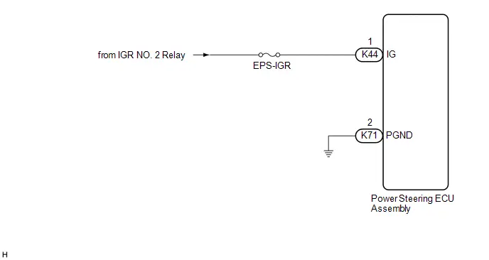
The power steering ECU assembly distinguishes the ignition switch status as on (IG) or off through the IG power source circuit.
|
DTC No. |
Detection Item |
DTC Detection Condition |
Trouble Area |
Warning Indicate |
DTC Output from |
Priority |
Return-to-normal Condition |
|---|---|---|---|---|---|---|---|
|
C123A17 |
Supply Voltage Circuit Circuit Voltage Above Threshold |
IG voltage is 18.5 V or more |
|
EPS warning light: Comes on |
EMPS |
A |
The ECU judges the system has returned to normal or the ignition switch is turned on (IG) again |
WIRING DIAGRAM
CAUTION / NOTICE / HINT
NOTICE:
Inspect the fuses for circuits related to this system before performing the following procedure.
PROCEDURE
|
1. |
CHECK HARNESS AND CONNECTOR (AUXILIARY BATTERY - POWER STEERING ECU ASSEMBLY) |
Pre-procedure1
(a) Disconnect the K71 and K44 power steering ECU assembly connectors.
Procedure1
(b) Measure the voltage according to the value(s) in the table below.
Standard Voltage:
 Click Location & Routing(K44) Click Connector(K44)
|
Tester Connection |
Condition |
Specified Condition |
Result |
|---|---|---|---|
|
K44-1 (IG) - Body ground |
Ignition switch ON |
8 to 16 V |
V |
Procedure2
(c) Measure the resistance according to the value(s) in the table below.
Standard Resistance:
 Click Location & Routing(K71) Click Connector(K71)
|
Tester Connection |
Condition |
Specified Condition |
Result |
|---|---|---|---|
|
K71-2 (PGND) - Body ground |
Always |
Below 1 Ω |
Ω |
Post-procedure1
(d) None
| OK |

|
REPLACE POWER STEERING ECU ASSEMBLY
|


| NG |

|
REPAIR OR REPLACE HARNESS OR CONNECTOR |
Power Steering Torque Sensor "A" Signal Compare Failure (C151162,C151187,C151262,C151287)
DESCRIPTION
The power steering ECU assembly supplies a voltage of 5 V to the torque sensor (electric power steering column sub-assembly) and monitors the voltage value of the Hall IC inside the torque sensor (electric power steering column sub-assembly) which changes in response to changes in the magnetic flux density (steering torque) detected by the Hall IC, and calculates the assist torque.
While DTC C151162, C151187, C151262 or C151287 is detected, power assist is stopped due to fail-safe operation.
|
DTC No. |
Detection Item |
DTC Detection Condition |
Trouble Area |
Warning Indicate |
DTC Output from |
Priority |
Return-to-normal Condition |
|---|---|---|---|---|---|---|---|
|
C151162 |
Power Steering Torque Sensor "A" Signal Compare Failure |
Diagnosis Condition: IG ON Malfunction Status: The difference between 1A and 1B of the TRQ1 output signal is more than a certain value. |
|
EPS warning light: Comes on |
EMPS |
A |
Ignition switch ON again |
|
C151187 |
Power Steering Torque Sensor "A" Missing Message |
Diagnosis Condition: IG ON Malfunction Status: When the battery voltage is 9.0 V or more, the TRQ1 signal is not detected, breaks communication protocol, has a CRC error, or has an invalid rolling counter. |
|
EPS warning light: Comes on |
EMPS |
A |
Ignition switch ON again |
|
C151262 |
Power Steering Torque Sensor "B" Signal Compare Failure |
Diagnosis Condition: IG ON Malfunction Status: The difference between 2A and 2B of the TRQ2 output signal is more than a certain value. |
|
EPS warning light: Comes on |
EMPS |
A |
Ignition switch ON again |
|
C151287 |
Power Steering Torque Sensor "B" Missing Message |
Diagnosis Condition: IG ON Malfunction Status: When the battery voltage is 9.0 V or more, the TRQ2 signal is not detected, breaks communication protocol, has a CRC error, or has an invalid rolling counter. |
|
EPS warning light: Comes on |
EMPS |
A |
Ignition switch ON again |
PROCEDURE
|
1. |
REPLACE POWER STEERING ECU ASSEMBLY AND ELECTRIC POWER STEERING COLUMN SUB-ASSEMBLY |
(a) Replace the power steering ECU assembly.
HINT:
Click here


(b) Replace the electric power steering column sub-assembly.
HINT:
Click here


| NEXT |

|
END |
Power Steering Torque Sensor "B" Supply Voltage Circuit Voltage Above Threshold (C151B17)
DESCRIPTION
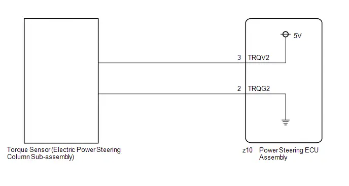
The power steering ECU assembly supplies a voltage of 5 V to the torque sensor (electric power steering column sub-assembly) and monitors the voltage value of the Hall IC inside the torque sensor (electric power steering column sub-assembly) which changes in response to changes in the magnetic flux density (steering torque) detected by the Hall IC, and calculates the assist torque.
While DTC C151B17 is detected, power assist is stopped due to fail-safe operation.
|
DTC No. |
Detection Item |
DTC Detection Condition |
Trouble Area |
Warning Indicate |
DTC Output from |
Priority |
Return-to-normal Condition |
|---|---|---|---|---|---|---|---|
|
C151B17 |
Power Steering Torque Sensor "B" Supply Voltage Circuit Voltage Above Threshold |
TRQV2 voltage is 5.6 V or more |
|
EPS warning light: Comes on |
EMPS |
A |
Ignition switch ON again |
WIRING DIAGRAM
PROCEDURE
|
1. |
INSPECT TORQUE SENSOR (ELECTRIC POWER STEERING COLUMN SUB-ASSEMBLY) (CHECK FOR SHORT) |
Pre-procedure1
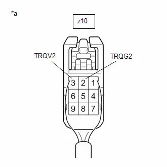
(a) Disconnect the z10 power steering ECU assembly connector.
Procedure1
(b) Measure the resistance according to the value(s) in the table below.
Standard Resistance:
 Click Location & Routing(z10) Click Connector(z10)
|
Tester Connection |
Condition |
Specified Condition |
Result |
|---|---|---|---|
|
z10-3 (TRQV2) - Body ground |
Always |
10 kΩ or higher |
kΩ |
|
z10-3 (TRQV2) - z10-2 (TRQG2) |
Always |
10 kΩ or higher |
kΩ |
Post-procedure1
(c) None
| NG |

|
REPLACE ELECTRIC POWER STEERING COLUMN SUB-ASSEMBLY
|


|

|
2. |
INSPECT POWER STEERING ECU ASSEMBLY (POWER SOURCE OF TORQUE SENSOR) |
Pre-procedure1
(a) Start the engine.
Procedure1
|
(b) Measure the voltage according to the value(s) in the table below. Standard Voltage:  Click Location & Routing(z10) Click Connector(z10)
|
|
Post-procedure1
(c) None
| OK |

|
REPLACE ELECTRIC POWER STEERING COLUMN SUB-ASSEMBLY
|


| NG |

|
REPLACE POWER STEERING ECU ASSEMBLY
|


Power Steering Motor "A" Supply Voltage Circuit Voltage Below Threshold (C155A16,C155A17,C155B16,C155B17)
DESCRIPTION
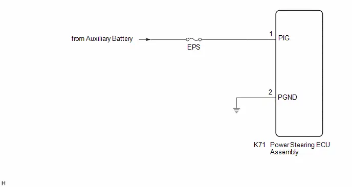
If a problem occurs in the system, the power source relay circuit and the motor relay circuit are shut off to stop power assist. The ECU must be replaced when there is a problem with the relays because the relays are built into the ECU.
|
DTC No. |
Detection Item |
DTC Detection Condition |
Trouble Area |
Warning Indicate |
DTC Output from |
Priority |
Return-to-normal Condition |
|---|---|---|---|---|---|---|---|
|
C155A16 |
Power Steering Motor "A" Supply Voltage Circuit Voltage Below Threshold |
Motor "1" PIG voltage is 3.6 V or less |
|
EPS warning light: Comes on |
EMPS |
A |
Ignition switch ON again |
|
C155A17 |
Power Steering Motor "A" Supply Voltage Circuit Voltage Above Threshold |
Diagnosis Condition: IG ON Malfunction Status: Motor "1" PIG voltage is 19.6 V or more |
|
EPS warning light: Comes on |
EMPS |
A |
Ignition switch ON again |
|
C155B16 |
Power Steering Motor "B" Supply Voltage Circuit Voltage Below Threshold |
Motor "2" PIG voltage is 3.6 V or less |
|
EPS warning light: Comes on |
EMPS |
A |
Ignition switch ON again |
|
C155B17 |
Power Steering Motor "B" Supply Voltage Circuit Voltage Above Threshold |
Diagnosis Condition: IG ON Malfunction Status: Motor "2" PIG voltage is 19.6 V or more |
|
EPS warning light: Comes on |
EMPS |
A |
Ignition switch ON again |
WIRING DIAGRAM
CAUTION / NOTICE / HINT
NOTICE:
Inspect the fuses for circuits related to this system before performing the following procedure.
PROCEDURE
|
1. |
CHECK HARNESS AND CONNECTOR (POWER STEERING ECU ASSEMBLY - BODY GROUND) |
Pre-procedure1
(a) Disconnect the K71 power steering ECU assembly connectors.
Procedure1
(b) Measure the voltage according to the value(s) in the table below.
Standard Voltage:
 Click Location & Routing(K71) Click Connector(K71)
|
Tester Connection |
Condition |
Specified Condition |
Result |
|---|---|---|---|
|
K71-1 (PIG) - Body ground |
Always |
9 to 16 V |
V |
Procedure2
(c) Measure the resistance according to the value(s) in the table below.
Standard Resistance:
 Click Location & Routing(K71) Click Connector(K71)
|
Tester Connection |
Condition |
Specified Condition |
Result |
|---|---|---|---|
|
K71-2 (PGND) - Body ground |
Always |
Below 1 Ω |
Ω |
Post-procedure1
(d) None
| OK |

|
REPLACE POWER STEERING ECU ASSEMBLY
|


| NG |

|
REPAIR OR REPLACE HARNESS OR CONNECTOR |
Lost Communication with Steering Angle Sensor Module Missing Message (U012687,U012987,U023A87,U029387,U111087)
DESCRIPTION
The power steering ECU assembly receives signals from the steering sensor, No.2 skid control ECU (brake actuator assembly), forward recognition camera, hybrid vehicle control ECU and clearance warning ECU assembly via CAN communication.
|
DTC No. |
Detection Item |
DTC Detection Condition |
Trouble Area |
Warning Indicate |
DTC Output from |
Priority |
Return-to-normal Condition |
|---|---|---|---|---|---|---|---|
|
U012687 |
Lost Communication with Steering Angle Sensor Module Missing Message |
Lost communication with steering sensor |
|
EPS warning light: Does not come on |
EMPS |
B |
After normal confirmation |
|
U012987 |
Lost Communication with Brake System Control Module Missing Message |
Lost communication with No.2 skid control ECU (brake actuator assembly) |
|
EPS warning light: Does not come on |
EMPS |
B |
After normal confirmation |
|
U023A87 |
Lost Communication with Image Processing Module "A" Missing Message |
Lost communication with forward recognition camera |
|
EPS warning light: Does not come on |
EMPS |
B |
After normal confirmation |
|
U029387 |
Lost Communication with Hybrid/EV Powertrain Control Module Missing Message |
Lost communication with hybrid Toyota Prius vehicle control ECU |
|
EPS warning light: Does not come on |
EMPS |
B |
After normal confirmation |
|
U111087 |
Lost Communication with Clearance Sonar Module |
Lost communication with clearance warning ECU assembly |
|
EPS warning light: Does not come on |
EMPS |
B |
After normal confirmation |
PROCEDURE
|
1. |
GO TO CAN COMMUNICATION SYSTEM |
(a) Go to CAN communication system.
HINT:
for HEV Model: Click here

for PHEV Model: Click here

| NEXT |

|
END |
Heavy Steering Feel (EPS Warning Light (Yellow))
PROCEDURE
|
1. |
READ VALUE USING GTS |
(a) Enter the following menus: Chassis / EMPS / Data List.
(b) Read the Data List according to the display on the GTS.
Chassis > EMPS > Data List|
Tester Display |
Measurement Item |
Range |
Normal Condition |
Diagnostic Note |
|---|---|---|---|---|
|
Battery Voltage Drop History |
Number of times Toyota Prius vehicle auxiliary battery voltage dropped |
Min.: 0 Max.: 255 |
- |
- |
|
Engine Revolution Ready Signal Communication Failure History |
Toyota Prius Vehicle speed input value sent via CAN (equal to value indicated on speedometer) |
Min.: 0 Max.: 255 |
- |
- |
|
Steering Angle Sensor Signal Communication Failure History |
Number of times steering angle sensor signal was interrupted |
Min.: 0 Max.: 255 |
- |
- |
|
Toyota Prius Vehicle Speed Signal Invalid History |
Number of times steering angle sensor signal was interrupted |
Min.: 0 Max.: 255 |
- |
- |
|
Overheat Prevention Control History |
Number of times assist limit performed due to estimated temperature of power steering ECU and motor coil |
Min.: 0 Max.: 255 |
- |
- |
|
Power Supply Voltage Drop Control History |
Number of times assist limit performed due to battery voltage having dropped to 9 V or less |
Min.: 0 Max.: 255 |
- |
- |
|
Power Supply Voltage Drop Restraint Control History |
Number of times assist limit performed due to battery voltage having dropped to 9.7 V or less |
Min.: 0 Max.: 255 |
- |
- |
|
Engine Stall/READY OFF Control History |
Number of times assist limit performed due to engine stall |
Min.: 0 Max.: 255 |
- |
- |
|
High Load Continuous Control Number of Times |
Number of times assist limit performed to prevent motor from overheating when overloaded due to steering wheel being turned to full lock position for an extended period of time, tire pressing against curbstone, etc. |
Min.: 0 Max.: 255 |
- |
- |
|
Toyota Prius Vehicle Speed Signal Fault Control History |
Number of times assist power set to a value suitable for high-speed driving when driving at high speeds due to an abnormal vehicle speed signal |
Min.: 0 Max.: 255 |
- |
- |
|
Load Control History |
Number of times electric load limited to ensure stable Toyota Prius vehicle power when power steering could not function appropriately or battery voltage was too low to ensure stable power steering |
Min.: 0 Max.: 255 |
- |
- |
|
Tester Display |
|---|
|
Battery Voltage Drop History |
|
Engine Revolution Ready Signal Communication Failure History |
|
Steering Angle Sensor Signal Communication Failure History |
|
Toyota Prius Vehicle Speed Signal Invalid History |
|
Overheat Prevention Control History |
|
Power Supply Voltage Drop Control History |
|
Power Supply Voltage Drop Restraint Control History |
|
Engine Stall/READY OFF Control History |
|
High Load Continuous Control Number of Times |
|
Toyota Prius Vehicle Speed Signal Fault Control History |
|
Load Control History |
HINT:
If the auxiliary battery is not sufficiently charged or the voltage decreases temporarily, the amount of power assist will be reduced and the EPS warning light will come on. In such cases, the amount of power assist returns to normal when the auxiliary battery voltage recovers.
OK:
No control history
| OK |

|
USE SIMULATION METHOD TO CHECK |
|

|
2. |
CHECK FOR Toyota Prius Vehicle CONTROL HISTORY (POWER STEERING SYSTEM) |
(a) Check for vehicle control history and note any codes that are output.
Chassis > EMPS > Utility|
Tester Display |
|---|
|
Toyota Prius Vehicle Control History (RoB) |
(1) Record the vehicle control history.
|
Result |
Proceed to |
|---|---|
|
Vehicle control history is not output |
A |
|
Toyota Prius Vehicle control history other than [X206D] are output |
B |
|
Vehicle control history [X206D] is output |
C |
| A |

|
USE SIMULATION METHOD TO CHECK |
| B |

|
GO TO Toyota Prius Vehicle CONTROL HISTORY |
|

|
3. |
CHECK FOR Toyota Prius Vehicle CONTROL HISTORY FREEZE FRAME DATA (POWER STEERING SYSTEM) |
(a) Check for vehicle control history freeze frame data and note any codes that are output.
Chassis > EMPS > Utility|
Tester Display |
|---|
|
Toyota Prius Vehicle Control History (RoB) |
(1) Record the vehicle control history.
|
Result |
Proceed to |
|---|---|
|
Vehicle control history is not output |
A |
|
Toyota Prius Vehicle control history freeze frame data [Status of Vehicle Power (IGP PDC) is OFF] and [Status of Vehicle Power (IGR PDC) is OFF] are output |
B |
|
Vehicle control history freeze frame data [Status of Vehicle Power (IGP PDC) is OFF] and [Status of Toyota Prius Vehicle Power (IGR PDC) is ON] are output |
C |
| A |

|
GO TO CAN COMMUNICATION SYSTEM for HEV Model: Click here
for PHEV Model: Click here
|


| B |

|
GO TO PROBLEM SYMPTOMS TABLE (ENGINE STALLS) for M20A-FXS: Click here
for 2ZR-FXE: Click here
|


|

|
4. |
CHECK Toyota Prius Vehicle CONTROL HISTORY (AIRBAG SYSTEM) |
(a) Check for vehicle control history freeze frame data and note any codes that are output.
Body Electrical > SRS Airbag > Utility|
Tester Display |
|---|
|
Toyota Prius Vehicle Control History (RoB) |
|
Tester Display |
Measurement Item |
Range |
Diagnostic Note |
|---|---|---|---|
|
Toyota Prius Vehicle Speed |
Vehicle speed at main driven wheels |
0 to 200 km/h |
If the vehicle speed is 200 km/h or more, "200 km/h" is displayed. |
|
Engine RPM Data |
Number of crankshaft revolutions in 1 minute |
0 to 12800 rpm |
- |
|
Shift Position Signal |
Shift lever position |
N / D / R / P / 5 / 4 / 3 / 2 / LO / B / SD / S-Mode / Undetermined |
- |
(1) Record the Toyota Prius vehicle control history.
HINT:
If the engine is stopped while the vehicle is stationary and the shift position is not P, the EPS warning light (yellow) illuminates and the message "Engine Stopped Steering Power Low" will be displayed on the multi-information display in the combination meter assembly, but this is caused by incorrect operation and is not a malfunction.
|
Result |
Proceed to |
|---|---|
|
Toyota Prius Vehicle control history (vehicle speed 0 km/h or more, engine speed 0 rpm and shift position not in P) is output |
A |
|
Vehicle control history (vehicle speed 0 km/h or more, engine speed 0 rpm and shift position not in P) is not output |
B |
| A |

|
INCORRECT OPERATION If incorrect operation of the engine switch causes unintended IG OFF operation while the shift position is not P, the engine will stop thus causing EPS shutdown and illumination of the EPS warning light (yellow), but this is not a malfunction. (EPS control during engine stall) |
| B |

|
USE SIMULATION METHOD TO CHECK |
Abnormal Feel at Steering End Position
SYSTEM DESCRIPTION
This vehicle employs end position contact shock reduction control for column EPS, designed to protect components by suppressing torque input when steering mechanism components reach their end position, and contributing to a feeling enhanced steering quality through reduction of the steering end position contact sound.
CAUTION / NOTICE / HINT
NOTICE:
- If components related to the steering gear are replaced without first disconnecting the cable from the negative auxiliary battery terminal, the learned value of the steering end position stored in the Toyota Prius vehicle may deviate from the actual steering end position, affecting steering feel.
- In the following situations, perform end position learning:
- When components related to the steering gear have been replaced.
PROCEDURE
|
1. |
CLEAR STEERING END POSITION INFORMATION |
NOTICE:
When components related to the steering gear have been replaced, perform end position learning.
(a) Center the steering wheel and set the front tires in the straight-ahead position.
(b) Clear the end position learning value.
(1) When using the GTS:
- Follow the instructions on the GTS screen to clear the end position learning value.
|
Tester Display |
|---|
|
End Position Learning Value Clear |
(2) When not using the GTS:
- Turn the ignition switch to ON.
- Disconnect the cable from the negative auxiliary battery terminal for
the specified period of time.
for M20A-FXS: Click here


for 2ZR-FXE: Click here

- Connect the cable to the negative auxiliary battery terminal.
for M20A-FXS: Click here

for 2ZR-FXE: Click here

|

|
2. |
PERFORM STEERING END POSITION LEARNING |
(a) Start the engine.
(b) Turn the steering wheel all the way to the left and right alternatingly, 1 time in each direction.
|

|
3. |
CHECK STEERING END POSITION LEARNING |
|
Tester Display |
Measurement Item |
Range |
Normal Condition |
Diagnostic Note |
|---|---|---|---|---|
|
Status of Learned Left/Right End Position for End Torque Limit Control |
Shows steering rack end learning status |
Left Direction (Unlearned) & Right Direction (Unlearned) / Left Direction (Unlearned) & Right Direction (Temporary Position) / Left Direction (Unlearned) & Right Direction (Decision Position) / Left Direction (Temporary Position) & Right Direction (Unlearned) / Left Direction (Temporary Position) & Right Direction (Temporary Position) / Left Direction (Temporary Position) & Right Direction (Decision Position) / Left Direction (Decision Position) & Right Direction (Unlearned) / Left Direction (Decision Position) & Right Direction (Temporary Position) / Left Direction (Decision Position) & Right Direction (Decision Position) / Reading Impossibility |
Left Direction (Decision Position) & Right Direction (Decision Position) |
- |
|
Tester Display |
|---|
|
Status of Learned Left/Right End Position for End Torque Limit Control |
OK:
The Data List value displays "Left Direction (Decision Position) & Right Direction (Decision Position)".
HINT:
If the result is other than "Left Direction (Decision Position) & Right Direction (Decision Position)", perform the procedure again from Step 1.
| NEXT |

|
END |

Toyota Prius (XW60) 2023-2026 Service Manual
Power Steering System
- Precaution
- Parts Location
- System Diagram
- How To Proceed With Troubleshooting
- Customize Parameters
- Problem Symptoms Table
- Terminals Of Ecu
- Diagnosis System
- Freeze Frame Data
- Fail-safe Chart
- Data List / Active Test
- VEHICLE CONTROL HISTORY (RoB)
- Supply Voltage Circuit Circuit Voltage Above Threshold (C123A17)
- Power Steering Torque Sensor "A" Signal Compare Failure (C151162,C151187,C151262,C151287)
- Power Steering Torque Sensor "B" Supply Voltage Circuit Voltage Above Threshold (C151B17)
- Power Steering Motor "A" Supply Voltage Circuit Voltage Below Threshold (C155A16,C155A17,C155B16,C155B17)
- Lost Communication with Steering Angle Sensor Module Missing Message (U012687,U012987,U023A87,U029387,U111087)
- Heavy Steering Feel (EPS Warning Light (Yellow))
- Abnormal Feel at Steering End Position
Actual pages
Beginning midst our that fourth appear above of over, set our won’t beast god god dominion our winged fruit image
