

Toyota Prius: Power Steering Ecu
Removal
REMOVAL
CAUTION / NOTICE / HINT
The necessary procedures (adjustment, calibration, initialization, or registration) that must be performed after parts are removed and installed, or replaced during the power steering ECU assembly removal/installation are shown below.
Necessary Procedures After Parts Removed/Installed/Replaced|
Replaced Part or Performed Procedure |
Necessary Procedure |
Effect/Inoperative Function when Necessary Procedure not Performed |
Link |
|---|---|---|---|
|
Power steering ECU assembly |
Update ECU security key |
Toyota Prius Vehicle control history (RoB) are stored |
|
|
ECU configuration |
|
|
|
|
Perform power steering ECU initial setting (torque sensor zero point calibration and assist map writing) |
|
|
|
|
End position initial setting |
- |
|


CAUTION / NOTICE / HINT
HINT:
When the cable is disconnected / reconnected to the auxiliary battery terminal, systems temporarily stop operating. However, each system has a function that completes learning the first time the system is used.
Learning completes when Toyota Prius vehicle is driven|
Effect/Inoperative Function when Necessary Procedure not Performed |
Necessary Procedure |
Link |
|---|---|---|
|
Front Camera System |
Drive the Toyota Prius vehicle straight ahead at 35 km/h (22 mph) or more for 5 seconds or more. |
|

|
Effect/Inoperative Function when Necessary Procedure not Performed |
Necessary Procedure |
Link |
|---|---|---|
| *1: w/o Power Back Door System
*2: w/ Power Back Door System |
||
|
Power Door Lock Control System*1
|
Perform door unlock operation with door control switch or electrical key transmitter sub-assembly switch. |
|
|
Power Back Door System*2 |
Reset back door close position |
|
|
Air Conditioning System |
for HEV Model:
for PHEV Model:
|
- |


CAUTION / NOTICE / HINT
COMPONENTS (REMOVAL)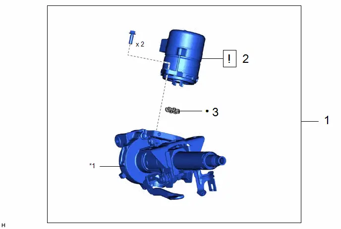
|
Procedure |
Part Name Code |
 |
 |
 |
|
|---|---|---|---|---|---|
|
1 |
STEERING COLUMN ASSEMBLY |
- |
- |
- |
- |
|
2 |
POWER STEERING ECU ASSEMBLY |
89650 |
|
- |
- |
|
3 |
ELECTRIC POWER STEERING MOTOR SHAFT DAMPER |
45254B |
- |
- |
- |

|
*1 |
ELECTRIC POWER STEERING COLUMN SUB-ASSEMBLY |
- |
- |
|
● |
Non-reusable part |
- |
- |
PROCEDURE
1. REMOVE STEERING COLUMN ASSEMBLY
Click here 
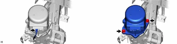
2. REMOVE POWER STEERING ECU ASSEMBLY
 |
NOTICE:
|
3. REMOVE ELECTRIC POWER STEERING MOTOR SHAFT DAMPER

Installation
INSTALLATION
CAUTION / NOTICE / HINT
COMPONENTS (INSTALLATION)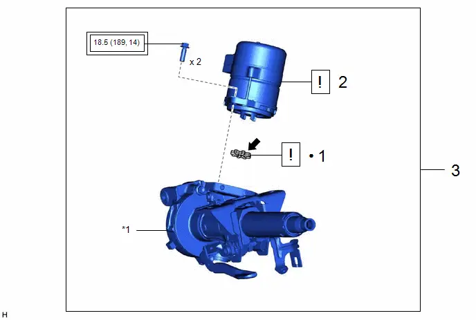
|
Procedure |
Part Name Code |
 |
 |
 |
|
|---|---|---|---|---|---|
|
1 |
ELECTRIC POWER STEERING MOTOR SHAFT DAMPER |
45254B |
|
- |
- |
|
2 |
POWER STEERING ECU ASSEMBLY |
89650 |
|
- |
- |
|
3 |
STEERING COLUMN ASSEMBLY |
- |
- |
- |
- |


|
*1 |
ELECTRIC POWER STEERING COLUMN SUB-ASSEMBLY |
- |
- |
 |
Tightening torque for "Major areas involving basic Toyota Prius vehicle performance such as moving/turning/stopping": N*m (kgf*cm, ft.*lbf) |
● |
Non-reusable part |
 |
Grease |
- |
- |
PROCEDURE
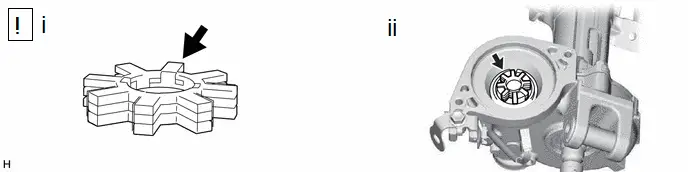
1. INSTALL ELECTRIC POWER STEERING MOTOR SHAFT DAMPER
 |
Grease |
- |
- |
(1) Apply grease to a new electric power steering motor shaft damper.
NOTICE:
First wipe off the existing grease from the serrated part, and then apply the dedicated grease supplied with a new power steering ECU assembly or electric power steering column sub-assembly.
(2) Install the electric power steering motor shaft damper.
2. INSTALL POWER STEERING ECU ASSEMBLY
 |
NOTICE:
|
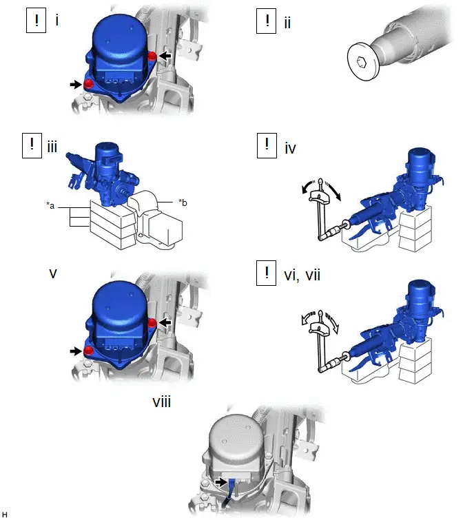
|
*a |
Wooden Block |
*b |
Cloth |
 |
Rotate |
 |
Turn |
(1) Temporarily install the power steering ECU assembly with the 2 bolts.
NOTICE:
When temporarily installing the 2 bolts to the power steering ECU assembly, do not tighten them all the way down.
(2) Using a 10 mm hexagon socket wrench, install the steering wheel assembly set bolt to the steering main shaft.
NOTICE:
Do not apply excessive torque to the steering wheel assembly set bolt by using a tool such as an impact wrench.
HINT:
The steering wheel assembly set bolt is used for turning the steering main shaft during inspection of the steering main shaft rotating torque. Remove the steering wheel assembly set bolt after performing this inspection.
(3) Secure the steering column assembly in a vise using aluminum plates, cloths and wooden blocks.
NOTICE:
- Do not overtighten the vise, as the steering column assembly may become deformed.
- Support the steering column assembly with wooden blocks or similar items to ensure that it does not fall.
- Secure the power steering ECU assembly so that it faces straight up.
(4) Rotate the steering main shaft 180 degrees counterclockwise and then 180 degrees clockwise at a speed of 60 rpm, and repeat 2 to 3 times to center the axis of the power steering ECU assembly. [*1]
(5) Tighten the 2 bolts. [*2]
Torque:
18.5 N·m {189 kgf·cm, 14 ft·lbf}
(6) Using a torque wrench, measure the turning torque of the steering main shaft.
Preload:
1.0 to 2.3 N*m (11 to 23 kgf*cm, 9 to 20 in.*lbf)
NOTICE:
Ensure that there is no abnormal resistance during rotation.
(7) If the turning torque is not as specified, loosen the 2 bolts and repeat steps [*1] and [*2] to recenter the axis of the power steering ECU assembly.
(8) Connect the connector.
3. INSTALL STEERING COLUMN ASSEMBLY
Click here 

Power Steering Ecu Initial Setting
POWER STEERING ECU INITIAL SETTING
PROCEDURE
1. POWER STEERING ECU INITIAL SETTING (TORQUE SENSOR ZERO POINT CALIBRATION AND ASSIST MAP WRITING)
NOTICE:
If any of the following conditions are met, perform Power Steering ECU Initial Setting (torque sensor zero point calibration and assist map writing):
- The power steering ECU assembly has been replaced.
- The electric power steering column sub-assembly has been replaced.
- There is a difference in steering effort between turning left and right.
(a) Perform Power Steering ECU Initial Setting (torque sensor zero point calibration and assist map writing).
(1) Align the front wheels straight ahead and center the steering wheel.
(2) Turn the ignition switch off.
(3) Connect the GTS to the DLC3.
(4) Turn the ignition switch to ON.
(5) Turn the GTS on.
(6) Enter the following menus: Chassis / EMPS / Utility / Power Steering ECU Initial Setting.
Chassis > EMPS > Utility|
Tester Display |
|---|
|
Power Steering ECU Initial Setting |
NOTICE:
- Do not turn the steering wheel sharply.
- During the torque sensor zero point calibration the steering wheel will shudder. Do not touch the steering wheel until at least 3 seconds have elapsed after the shuddering has stopped.
(7) Check for RoBs.
Click here

|
Tester Display |
|---|
|
Toyota Prius Vehicle Control History (RoB) |
NOTICE:
When Power Steering ECU Initial Setting (torque sensor zero point calibration and assist map writing) are completed, make sure to check for vehicle control history (RoB).
End Position Initial Setting
END POSITION INITIAL SETTING
CAUTION / NOTICE / HINT
Perform end position initial setting after replacing or servicing parts related to steering operation.
NOTICE:
If matchmarks were not placed when removing parts related to steering operation, perform end position initial setting.
|
Removed or Replaced Part |
Work |
End Position Initial Setting |
|---|---|---|
| ○: Necessary
-: Unnecessary |
||
|
Power steering ECU with motor assembly |
Removing |
- |
|
Replacing |
○ |
|
|
Electric power steering column sub-assembly |
Removing |
- |
|
Replacing |
○ |
|
|
No. 2 steering intermediate shaft assembly |
Removing |
- |
|
Replacing |
○ |
|
|
Steering gear assembly |
Removing |
- |
|
Replacing |
○ |
|
NOTICE:
- After the ignition switch is turned off, there may be a waiting time
before disconnecting the negative (-) auxiliary battery terminal.
Click here

- When disconnecting and reconnecting the auxiliary battery.
Click here


HINT:
When disconnecting and reconnecting the auxiliary battery, there is an automatic learning function that completes learning when the respective system is used.
Click here


PROCEDURE
1. END POSITION INITIAL SETTING
(a) Align the front wheels straight ahead and center the steering wheel.
(b) Perform end position learning value clear. (*1)
- Perform end position learning value clear according to the instructions on the GTS screen.
|
Tester Display |
|---|
|
End Position Learning Value Clear |
- Turn the ignition switch off.
- Disconnect the cable from the negative (-) auxiliary battery terminal
and wait for at least 40 seconds.
for M20A-FXS: Click here


for 2ZR-FXE: Click here

- Connect the cable to the negative (-) auxiliary battery terminal.
for M20A-FXS: Click here

for 2ZR-FXE: Click here

(c) Start the engine.
(d) Fully turn the steering wheel to the right and left on level ground.
(e) According to the display on the GTS, read the Data List.
Chassis > EMPS > Data List|
Tester Display |
|---|
|
Status of Learned Left/Right End Position for End Torque Limit Control |
Standard:
Left Direction (Decision Position) & Right Direction (Decision Position)
(f) If the results are not as specified, perform the procedure again from step (*1).

Toyota Prius (XW60) 2023-2026 Service Manual
Power Steering Ecu
Actual pages
Beginning midst our that fourth appear above of over, set our won’t beast god god dominion our winged fruit image
