

Toyota Prius: Oil Pump
Removal
REMOVAL
CAUTION / NOTICE / HINT
The necessary procedures (adjustment, calibration, initialization or registration) that must be performed after parts are removed and installed, or replaced during oil pump assembly removal/installation are shown below.
Necessary Procedures After Parts Removed/Installed/Replaced| Replaced Part or Performed Procedure | Necessary Procedure | Effect/Inoperative Function when Necessary Procedure not Performed | Link |
|---|---|---|---|
|
*: Even when not replacing the part, it is necessary to perform the specified necessary procedures after installation.
*1: Also necessary after performing a tire rotation. *2: It is not necessary to perform this procedure if the tire pressure warning valve and transmitters are installed to the same location. | |||
| Replacement of ECM | Update ECU security key | Toyota Prius Vehicle Control History (RoB) are stored |
|
| ECU configuration | - |
| |
| Perform Toyota Prius Vehicle Identification Number (VIN) registration | DTC is output |
| |
| Inspection after repair |
|
|
| Replacement of inverter with converter assembly | ECU configuration | - |
|
| Resolver learning |
|
| |
| Replacement of hybrid vehicle transaxle assembly |
|
|
|
| Suspension parts | Rear television camera assembly optical axis (Back camera position setting) | Parking Assist Monitor System |
|
| Parking assist ECU initialization | Panoramic View Monitor System |
| |
| Advanced Park |
| ||
| Tires |
| Tire Pressure Warning System | Refer to Procedures Necessary When Replacing Parts (for Tire Pressure Warning System) table below |
| Rear television camera assembly optical axis (Back camera position setting) | Parking Assist Monitor System |
| |
| Parking assist ECU initialization | Panoramic View Monitor System |
| |
| Advanced Park |
| ||
| Replacement of front bumper assembly* | Front television camera view adjustment | Panoramic View Monitor System |
|
| Advanced Park |
| ||


HINT:
When the cable is disconnected / reconnected to the auxiliary battery terminal, systems temporarily stop operating. However, each system has a function that completes learning the first time the system is used.
-
Learning completes when Toyota Prius vehicle is driven
Effect/Inoperative Function When Necessary Procedures are not Performed
Necessary Procedures
Link
Front Camera System
Drive the Toyota Prius vehicle straight ahead at 35 km/h (22 mph) or more for 5 seconds or more.

-
Learning completes when vehicle is operated normally
Effect/Inoperative Function When Necessary Procedures are not Performed
Necessary Procedures
Link
*1: w/o Power Back Door System *2: w/ Power Back Door System
Power Door Lock Control System*1
- Back door opener
Perform door unlock operation with door control switch or electrical key transmitter sub-assembly switch.

Power Back Door System*2
Reset back door close position

Air Conditioning System
After the ignition switch is turned to ON, the servo motor standard position is recognized.
-
CAUTION / NOTICE / HINT
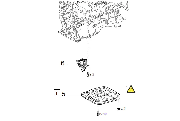
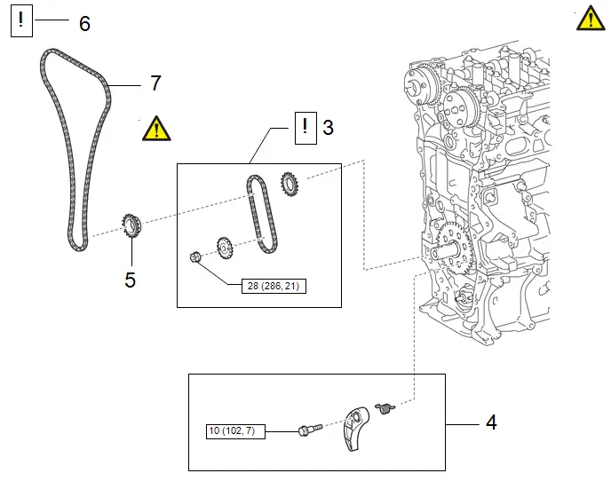
COMPONENTS (REMOVAL)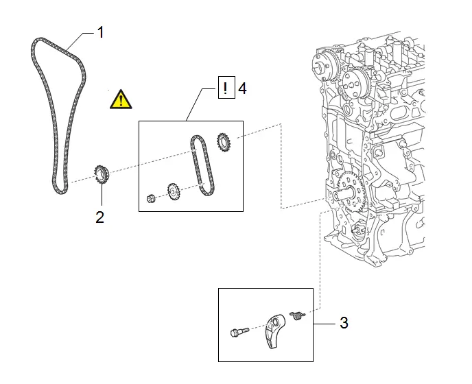
| Procedure | Part Name Code |

|

|

| |
|---|---|---|---|---|---|
| 1 | CHAIN SUB-ASSEMBLY | 13506 | - | - | - |
| 2 | CRANKSHAFT TIMING SPROCKET | 13521 | - | - | - |
| 3 | CHAIN TENSIONER PLATE | 13549 | - | - | - |
| 4 | NO. 2 CHAIN SUB-ASSEMBLY | 13507 |
| - | - |

| Procedure | Part Name Code |

|

|

| |
|---|---|---|---|---|---|
| 5 | NO. 2 OIL PAN SUB-ASSEMBLY | 12102A |
| - | - |
| 6 | OIL PUMP ASSEMBLY | 15100 | - | - | - |

PROCEDURE
1. REMOVE CHAIN SUB-ASSEMBLY
Click here

2. REMOVE CRANKSHAFT TIMING SPROCKET
Click here

3. REMOVE CHAIN TENSIONER PLATE
Click here

4. REMOVE NO. 2 CHAIN SUB-ASSEMBLY

| Click here
|

5. REMOVE NO. 2 OIL PAN SUB-ASSEMBLY

| Click here
|

6. REMOVE OIL PUMP ASSEMBLY

Disassembly
DISASSEMBLY
CAUTION / NOTICE / HINT
COMPONENTS (DISASSEMBLY)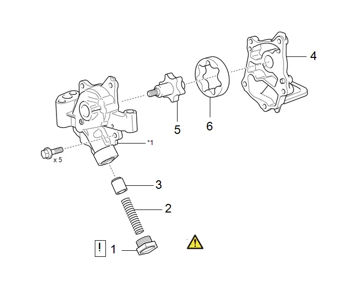
| Procedure | Part Name Code |

|

|

| |
|---|---|---|---|---|---|
| 1 | OIL PUMP RELIEF VALVE PLUG | - |
| - | - |
| 2 | OIL PUMP RELIEF VALVE SPRING | - | - | - | - |
| 3 | OIL PUMP RELIEF VALVE | - | - | - | - |
| 4 | OIL PUMP COVER SUB-ASSEMBLY | - | - | - | - |
| 5 | OIL PUMP DRIVE ROTOR | - | - | - | - |
| 6 | OIL PUMP DRIVEN ROTOR | - | - | - | - |

| *1 | OIL PUMP BODY | - | - |
PROCEDURE
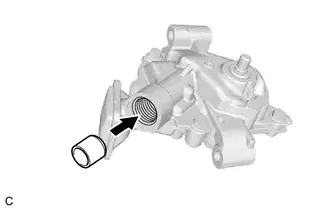
1. REMOVE OIL PUMP RELIEF VALVE PLUG
(1) Using a 27 mm socket wrench, remove the oil pump relief valve plug from the oil pump body.
2. REMOVE OIL PUMP RELIEF VALVE SPRING

3. REMOVE OIL PUMP RELIEF VALVE

4. REMOVE OIL PUMP COVER SUB-ASSEMBLY

5. REMOVE OIL PUMP DRIVE ROTOR

6. INSTALL OIL PUMP DRIVEN ROTOR

Inspection
INSPECTION
PROCEDURE
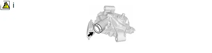
1. INSPECT OIL PUMP RELIEF VALVE
| (a) Coat the oil pump relief valve with engine oil, then check that it falls smoothly into the valve hole by its own weight. |
|
(b) If the oil pump relief valve does not fall smoothly, replace the oil pump assembly.
2. INSPECT OIL PUMP ROTOR
(a) Check the side clearance.
| (1) Using a feeler gauge and precision straightedge, measure the clearance between the oil pump drive rotor, oil pump driven rotor and precision straightedge. Standard Side Clearance:
|
|
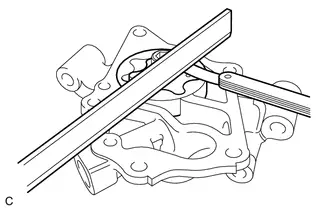
(2) If the side clearance is greater than the maximum, replace the oil pump assembly.
(b) Check the tip clearance.
| (1) Using a feeler gauge, measure the clearance between the oil pump drive rotor and oil pump driven rotor tips. Standard Tip Clearance:
|
|
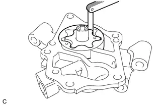
(2) If the tip clearance is greater than the maximum, replace the oil pump assembly.
(c) Check the body clearance.
| (1) Using a feeler gauge, measure the clearance between the oil pump driven rotor and oil pump body. Standard Body Clearance:
|
|
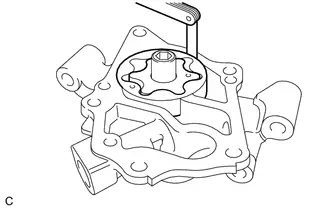
(2) If the body clearance is greater than the maximum, replace the oil pump assembly.
Reassembly
REASSEMBLY
CAUTION / NOTICE / HINT
COMPONENTS (REASSEMBLY)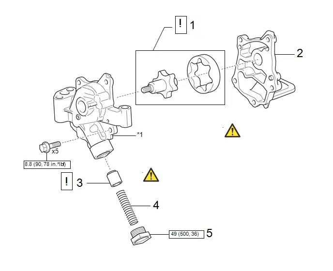
| Procedure | Part Name Code |

|

|

| |
|---|---|---|---|---|---|
| 1 | OIL PUMP DRIVE AND DRIVEN ROTORS | - |
| - | - |
| 2 | OIL PUMP COVER SUB-ASSEMBLY | - | - | - | - |
| 3 | OIL PUMP RELIEF VALVE | - |
| - | - |
| 4 | OIL PUMP RELIEF VALVE SPRING | - | - | - | - |
| 5 | OIL PUMP RELIEF VALVE PLUG | - | - | - | - |


| *1 | OIL PUMP BODY | - | - |

| N*m (kgf*cm, ft.*lbf): Specified torque | - | - |
PROCEDURE
1. INSTALL OIL PUMP DRIVE AND DRIVEN ROTORS
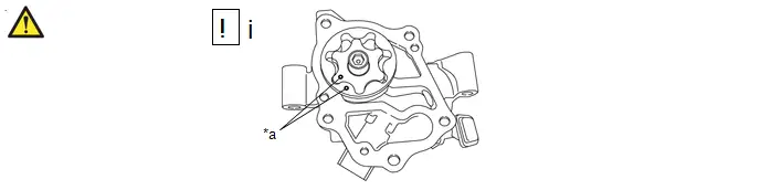
| *a | Mark | - | - |
(1) Coat the oil pump drive rotor and oil pump driven rotor with engine oil, and place them into the oil pump body with the marks facing the oil pump cover sub-assembly side.
2. INSTALL OIL PUMP COVER SUB-ASSEMBLY
Torque:
8.8 N·m {90 kgf·cm, 78 in·lbf}
3. INSTALL OIL PUMP RELIEF VALVE
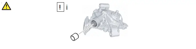
(1) Coat the oil pump relief valve with engine oil, and insert the oil pump relief valve into the oil pump body.
4. INSTALL OIL PUMP RELIEF VALVE SPRING
5. INSTALL OIL PUMP RELIEF VALVE PLUG
Torque:
49 N·m {500 kgf·cm, 36 ft·lbf}
Installation
INSTALLATION
CAUTION / NOTICE / HINT
COMPONENTS (INSTALLATION)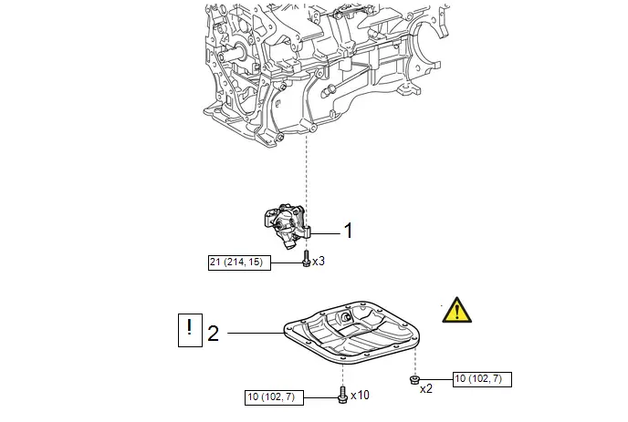
| Procedure | Part Name Code |

|

|

| |
|---|---|---|---|---|---|
| 1 | OIL PUMP ASSEMBLY | 15100 | - | - | - |
| 2 | NO. 2 OIL PAN SUB-ASSEMBLY | 12102A |
| - | - |


| N*m (kgf*cm, ft.*lbf): Specified torque | - | - |
| Procedure | Part Name Code |

|

|

| |
|---|---|---|---|---|---|
| 3 | NO. 2 CHAIN SUB-ASSEMBLY | 13507 |
| - | - |
| 4 | CHAIN TENSIONER PLATE | 13549 | - | - | - |
| 5 | CRANKSHAFT TIMING SPROCKET | 13521 | - | - | - |
| 6 | NO. 1 CYLINDER TO TDC (COMPRESSION) | - |
| - | - |
| 7 | CHAIN SUB-ASSEMBLY | 13506 | - | - | - |


PROCEDURE
1. INSTALL OIL PUMP ASSEMBLY
Torque:
21 N·m {214 kgf·cm, 15 ft·lbf}
2. INSTALL NO. 2 OIL PAN SUB-ASSEMBLY

| Click here
|

3. INSTALL NO. 2 CHAIN SUB-ASSEMBLY

| Click here
|

4. INSTALL CHAIN TENSIONER PLATE
Click here

5. INSTALL CRANKSHAFT TIMING SPROCKET
Click here

6. SET NO. 1 CYLINDER TO TDC (COMPRESSION)

| Click here
|

7. INSTALL CHAIN SUB-ASSEMBLY
Click here


Toyota Prius (XW60) 2023-2026 Service Manual
Oil Pump
Actual pages
Beginning midst our that fourth appear above of over, set our won’t beast god god dominion our winged fruit image
