

Toyota Prius: Occupant Classification System
- Precaution
- Parts Location
- System Diagram
- System Description
- How To Proceed With Troubleshooting
- Operation Check
- Initialization
- Problem Symptoms Table
- Terminals Of Ecu
- Freeze Frame Data
- Fail-safe Chart
- Data List / Active Test
- Diagnostic Trouble Code Chart
- VEHICLE CONTROL HISTORY (RoB)
- Passenger Seat Occupant Classification Sensor "A" Signal Bias Level Out of Range / Zero Adjustment Failure (B00C028)
- Passenger Seat Occupant Classification Sensor "A" Signal (some circuit quantity, reported via serial data) Invalid (B00C086)
- Passenger Seat Occupant Classification Sensor "A" Missing Message (B00C087)
- Passenger Seat Occupant Classification Sensor "A" Component Internal Failure (B00C096)
- Load Sensor for Occupant Detection System Circuit Short to Battery (B179312)
- Load Sensor for Occupant Detection System Circuit Voltage Below Threshold (B179316)
- Trouble in Passenger Airbag ON/OFF Indicator
- LIN Communication Circuit
Precaution
PRECAUTION
GENERAL PRECAUTION
(a) The following conditions may be interpreted as a malfunction even though they are normal operation:
- An object is placed on the front passenger seat and the system judges that an adult is seated. As the occupant classification system detects and classifies occupants based on weight, the system may detect an object placed on the seat cushion as an adult front passenger depending on its weight.
- Pressure is applied to the front passenger seat and the system judges that an adult is seated. As the occupant classification system detects and classifies occupants based on weight, the system may detect an adult front passenger if pressure is applied to the seat cushion by hands, etc.
- Illumination of the passenger airbag ON/OFF indicator does not change immediately after a front passenger is seated or leaves the Toyota Prius vehicle. To prevent the classification judgment from changing when a front passenger changes their seating posture, a certain amount of time is required to detect and classify an occupant when the calculated weight changes. Therefore, there will be a time lag between when a front passenger is seated or leaves the Toyota Prius vehicle and when the system detects the occupant.
(b) The zero point of the occupant classification sensors may deviate. To ensure sensor accuracy, be sure to perform Zero Point Calibration.
Click here

PRECAUTIONS FOR DISCONNECTING CABLE FROM NEGATIVE (-) AUXILIARY BATTERY TERMINAL
NOTICE:
-
After the ignition switch is turned off, there may be a waiting time before disconnecting the negative (-) auxiliary battery terminal.
Click here

HINT:
When disconnecting and reconnecting the auxiliary battery, there is an automatic learning function that completes learning when the respective system is used.
Click here


Parts Location
PARTS LOCATION
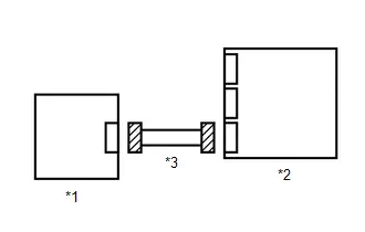
ILLUSTRATION
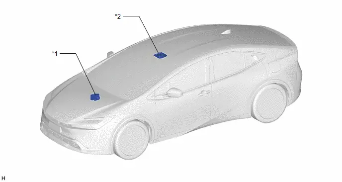
| *1 | BRAKE ACTUATOR ASSEMBLY - NO. 2 SKID CONTROL ECU | *2 | MAP LIGHT ASSEMBLY - PASSENGER AIRBAG ON/OFF INDICATOR |
ILLUSTRATION
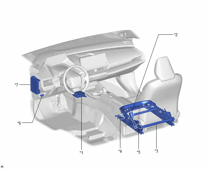
| *1 | AIRBAG ECU ASSEMBLY | *2 | FRONT SEAT INNER BELT ASSEMBLY RH - PASSENGER SEAT BUCKLE SWITCH |
| *3 | FRONT SEAT ADJUSTER ASSEMBLY RH | *4 | FRONT OCCUPANT CLASSIFICATION SENSOR LH |
| *5 | REAR OCCUPANT CLASSIFICATION SENSOR LH | *6 | DLC3 |
| *7 | POWER DISTRIBUTION BOX ASSEMBLY - A/BAG-IGR FUSE | - | - |
System Diagram
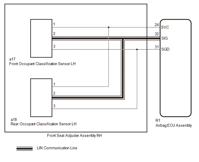
SYSTEM DIAGRAM
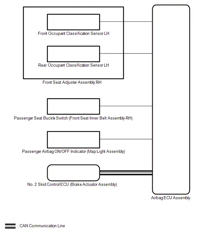 Communication Table
 | Transmitting ECU / Parts (Transmitter) | Receiving ECU (Receiver) | Signal | Communication Method |
|---|---|---|---|
| Passenger Seat Buckle Switch (Front Seat Inner Belt Assembly RH) | Airbag ECU Assembly | Front passenger side buckle switch signal | Direct line |
| Passenger Airbag ON/OFF Indicator (Map Light Assembly) | Airbag ECU Assembly |
| |
| Front Occupant Classification Sensor LH | Airbag ECU Assembly | Occupant load for front passenger signal | LIN |
| Rear Occupant Classification Sensor LH | Airbag ECU Assembly | ||
| No. 2 Skid Control ECU (Brake Actuator Assembly) | Airbag ECU Assembly |
| CAN |
System Description
SYSTEM DESCRIPTION
GENERAL
(a) The airbag ECU assembly estimates the weight of an occupant based on signals received from the 2 occupant classification sensors. The airbag ECU assembly determines whether the front passenger seat is occupied and classifies the occupant based on the estimated weight, front passenger side buckle switch state, acceleration sensor signal and Toyota Prius vehicle speed signal.
(b) The airbag ECU assembly controls the operation of the passenger airbag ON/OFF indicator and restricts the operation of the instrument panel passenger airbag assembly.
How To Proceed With Troubleshooting
CAUTION / NOTICE / HINT
HINT:
- Use the following procedure to troubleshoot the occupant classification system.
- *: Use the GTS.
PROCEDURE
| 1. | Toyota Prius Vehicle BROUGHT TO WORKSHOP |
|

| 2. | CUSTOMER PROBLEM ANALYSIS |
(a) Confirm problem symptoms.
Click here

|

| 3. | INSPECT AUXILIARY BATTERY VOLTAGE |
(a) Measure the auxiliary battery voltage with the ignition switch off.
Standard Voltage:
11 to 14 V
HINT:
- A simple method to determine whether the auxiliary battery is discharged is to operate the horn.
- If the voltage is below 11 V, recharge or replace the auxiliary battery before proceeding.
(b) Check the fuses and relays.
(c) Check the connector connections and terminals to make sure that there are no abnormalities such as loose connections, deformation, etc.
|

| 4. | CHECK CAN COMMUNICATION SYSTEM* |
(a) Using the GTS, check that the CAN communication system is functioning normally.
OK:
CAN communication system is functioning normally.
HINT:
-
Refer to CAN Bus Check in CAN Communication System.
for HEV Model: Click here

for PHEV Model: Click here

- The airbag ECU assembly is connected to the CAN communication system. Therefore, before starting troubleshooting, make sure to check that there are no malfunctions in the CAN communication system.
| NG |

| GO TO CAN COMMUNICATION SYSTEM for HEV Model: Click here
for PHEV Model: Click here
|


|

| 5. | CHECK PASSENGER AIRBAG ON/OFF INDICATOR |
(a) Refer to Operation Check.
Click here

|

| 6. | CHECK DTC* |
(a) Check for DTCs.
Body Electrical > SRS Airbag > Trouble CodesHINT:
Record or print DTCs if necessary.
| Result | Proceed to |
|---|---|
| No DTCs are output | A |
| Airbag system DTCs are output | B |
| Occupant classification system DTCs are output | C |
| A |

| GO TO PROBLEM SYMPTOMS TABLE |
| B |

| GO TO AIRBAG SYSTEM |
|

| 7. | CLEAR DTC* |
NOTICE:
Make sure to record any output Freeze Frame Data and Toyota Prius Vehicle Control History (RoB) codes before clearing them and checking the DTC again.
(a) Clear the DTCs.
Body Electrical > SRS Airbag > Clear DTCs
|

| 8. | CHECK DTC* |
(a) Check for DTCs.
Body Electrical > SRS Airbag > Trouble CodesHINT:
Record or print DTCs if necessary.
OK:
DTCs are not output.
| NG |

| GO TO DIAGNOSTIC TROUBLE CODE CHART |
|

| 9. | CHECK FOR Toyota Prius Vehicle CONTROL HISTORY* |
(a) Check for Vehicle Control History (RoB).
Body Electrical > SRS Airbag > Utility| Tester Display |
|---|
| Vehicle Control History (RoB) |
| Result | Proceed to |
|---|---|
| Toyota Prius Vehicle Control History (RoB) is not output | A |
| Vehicle Control History (RoB) is output | B |
| A |

| GO TO PROBLEM SYMPTOMS TABLE |
|

| 10. | CLEAR Toyota Prius Vehicle CONTROL HISTORY* |
NOTICE:
Make sure to record any output Freeze Frame Data and Vehicle Control History (RoB) codes before clearing them and checking the DTC again.
(a) Clear the Vehicle Control History (RoB).
Body Electrical > SRS Airbag > Utility| Tester Display |
|---|
| Toyota Prius Vehicle Control History (RoB) |
|

| 11. | CHECK FOR Toyota Prius Vehicle CONTROL HISTORY* |
(a) Check for Vehicle Control History (RoB).
Body Electrical > SRS Airbag > Utility| Tester Display |
|---|
| Vehicle Control History (RoB) |
| Result | Proceed to |
|---|---|
| Toyota Prius Vehicle Control History (RoB) is not output | A |
| Vehicle Control History (RoB) is output | B |
| A |

| USE SIMULATION METHOD TO CHECK |
| B |

| GO TO Toyota Prius Vehicle CONTROL HISTORY |
Operation Check
OPERATION CHECK
PRECAUTION FOR OPERATION CHECK
CAUTION:
Use the correct procedure to replace the airbag parts.
CHECK SRS WARNING LIGHT
(a) Primary check
(1) Turn the ignition switch to ON and check that the SRS warning light turns on.

(2) Turn the ignition switch off. Wait for at least 2 seconds, and then turn the ignition switch to ON. The SRS warning light comes on for approximately 6 seconds and diagnosis of the airbag system (including the seat belt pretensioners) is performed.
NOTICE:
Turn the ignition switch off when the auxiliary battery is connected.
HINT:
- If the SRS warning light remains on for approximately 6 seconds or more after the ignition switch has been turned to ON, there may be a malfunction with the airbag system.
- If the warning light occasionally turns on approximately 6 seconds or more after the ignition switch has been turned to ON, there may be a short to B, short to ground or an open in the SRS warning light circuit.
- If the warning light illuminates after turning the ignition switch off or to ACC, there may be a malfunction in the power source circuit or combination meter assembly.
- The SRS warning light turns off, and then turns on. This blinking pattern indicates a source voltage drop. The SRS warning light turns off 6 to 10 seconds after the source voltage returns to normal.
FUNCTION OF PASSENGER AIRBAG ON/OFF INDICATOR
(a) Initial check
(1) Turn the ignition switch to ON.
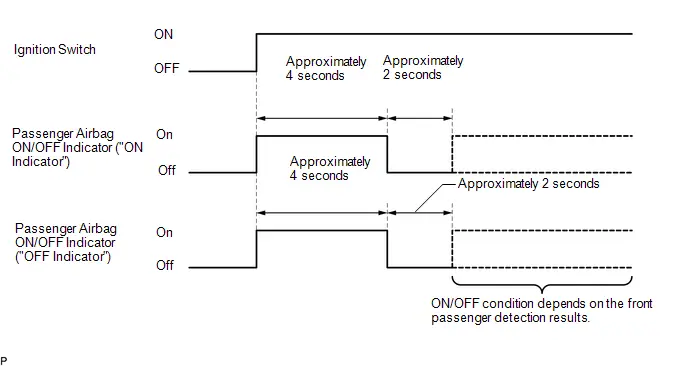
(2) The passenger airbag ON/OFF indicator comes on for approximately 4 seconds, and then goes off for approximately 2 seconds.
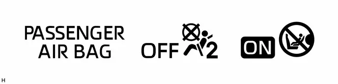
(3) Approximately 6 seconds after the ignition switch is turned to ON, the passenger airbag ON/OFF indicator will indicate ON/OFF depending on the following conditions.
Indicator Operation| Front Passenger Seat Condition | Passenger Airbag ON/OFF Indicator | SRS Warning Light | |
|---|---|---|---|
| ON Indicator | OFF Indicator | ||
| Vacant | OFF | ON | OFF |
| Adult*1 is seated | ON | OFF | OFF |
| Child*2 is seated | ON or OFF*2 | OFF or ON*2 | OFF |
| Child restraint system is installed | OFF | ON | OFF |
| Occupant classification system failure | OFF | ON | ON |
- *1: The system judges a person of average adult weight or more as an adult. If a smaller adult sits in the front passenger seat, the system may not recognize them as an adult depending on their physique and posture.
- *2: The system may not recognize a child or a child in a child restraint system as a child depending on factors such as the positioning of the child restraint system or the child's physique or posture.
HINT:
- The timing chart below shows the operation of the passenger airbag ON/OFF indicator. Use the chart to check the indicator light circuit.
- When the occupant classification system has trouble, both the SRS warning light and passenger airbag ON/OFF indicator ("OFF") come on. In this case, check for DTCs for "Airbag System" first.
Initialization
INITIALIZATION
DESCRIPTION
(a) The zero point of the occupant classification sensors may deviate in the following situations. To ensure sensor accuracy, be sure to perform Zero Point Calibration.
-
The airbag ECU assembly is replaced.
HINT:
As the zero point is not automatically stored in a new airbag ECU assembly, it is necessary to perform zero point calibration after replacing the airbag ECU assembly.
-
Accessories (seatback tray, seat cover, etc.) are installed or removed.
HINT:
As the weight of accessories will be added or decreased to the weight of the occupant, the system will not be able to perform classification accurately.
-
The front passenger seat is removed from the Toyota Prius vehicle.
HINT:
As the seat frame will warp slightly when the bolts that are used to install the front passenger seat are tightened, the load applied to the occupant classification sensor will change and the system will not be able to perform classification accurately.
-
Any of the bolts that are used to install the front passenger seat are removed and reinstalled.
HINT:
As the seat frame will warp slightly when the bolts that are used to install the front passenger seat are tightened, the load applied to the occupant classification sensor will change and the system will not be able to perform classification accurately.
-
The passenger airbag ON/OFF indicator ("ON") illuminates when the front passenger seat is not occupied or the airbag OFF indicator illuminates when the front passenger seat is occupied (by an adult).
HINT:
If any load or pressure is applied to the occupant classification sensors, the system will not be able to perform classification accurately.
-
An occupant classification sensor collision detection DTC is output due to an accident or a collision.
HINT:
If the seat frame or Toyota Prius vehicle floor has become deformed and additional pressure is applied to the occupant classification sensor, the system will not be able to perform classification accurately.
NOTICE:
Make sure that the front passenger seat is not occupied before performing the operation.
ZERO POINT CALIBRATION
(a) Zero point calibration procedure
(1) Check that all of the following conditions are met:
- The Toyota Prius vehicle is parked on a level surface.
- No objects are placed on the front passenger seat.
- No objects are touching the front passenger seat.
(2) Adjust the seat position according to the table below.
| Adjustment Item | Position |
|---|---|
| Slide Direction | Rearmost position |
| Headrest Height | Lowest position |
| Recline Angle | Upright position |
| Seat Lifter Height | Lowest position |
(3) Perform zero point calibration by following the prompts on the GTS screen.
Body Electrical > SRS Airbag > Utility| Tester Display |
|---|
| Occupant Detection Sensor Zero Point Calibration |
OK:
"Occupant Detection Sensor Zero Point Calibration is complete." is displayed.
(4) Clear the Toyota Prius Vehicle Control History (RoB).
Body Electrical > SRS Airbag > Utility| Tester Display |
|---|
| Vehicle Control History (RoB) |
(5) Check for Vehicle Control History (RoB).
Body Electrical > SRS Airbag > Utility| Tester Display |
|---|
| Toyota Prius Vehicle Control History (RoB) |
OK:
X20D0 is not output.
HINT:
- Refer to the GTS operator's manual for further details.
-
If Occupant Detection Sensor Zero Point Calibration does not complete normally, check the Error Code List to determine the cause of malfunction. Error Code List
Error Code
Item Name
Cause
Countermeasure
01
Out of FI Load Sensor Upper Limit Standard
When any of the following conditions is detected:- The sensor load value before learning is not as specified (upper limit exceeded)
- The sensor load value after learning is not as specified (upper limit exceeded)
Check for the following- Check whether the Toyota Prius vehicle and seat are subject to vibration or a load
-
Check front seat assembly RH installation

-
Perform Occupant Detection Sensor Zero Point Calibration again
HINT:
If the error code is output again, replace the front seat adjuster assembly RH (occupant classification sensor).


02
Out of FI Load Sensor Lower Limit Standard
When any of the following conditions is detected:- The sensor load value before learning is not as specified (below lower limit)
- The sensor load value after learning is not as specified (below lower limit)
Check for the following- Check whether the Toyota Prius vehicle and seat are subject to vibration or a load
-
Check front seat assembly RH installation

-
Perform Occupant Detection Sensor Zero Point Calibration again
HINT:
If the error code is output again, replace the front seat adjuster assembly RH (occupant classification sensor).


03
Out of RI Load Sensor Upper Limit Standard
When any of the following conditions is detected:- The sensor load value before learning is not as specified (upper limit exceeded)
- The sensor load value after learning is not as specified (upper limit exceeded)
Check for the following- Check whether the Toyota Prius vehicle and seat are subject to vibration or a load
-
Check front seat assembly RH installation

-
Perform Occupant Detection Sensor Zero Point Calibration again
HINT:
If the error code is output again, replace the front seat adjuster assembly RH (occupant classification sensor).


04
Out of RI Load Sensor Lower Limit Standard
When any of the following conditions is detected:- The sensor load value before learning is not as specified (below lower limit)
- The sensor load value after learning is not as specified (below lower limit)
Check for the following- Check whether the Toyota Prius vehicle and seat are subject to vibration or a load
-
Check front seat assembly RH installation

-
Perform Occupant Detection Sensor Zero Point Calibration again
HINT:
If the error code is output again, replace the front seat adjuster assembly RH (occupant classification sensor).


10
Nonvolatile Memory Storage Failure
When a memory malfunction caused by either of the following is detected:- Writing failure
- IGR low voltage (below 8 V)
Check for the following- Check for DTC
-
Check Toyota Prius Vehicle Control History (RoB)

-
Measure IGR terminal voltage

HINT:
If below 8 V, check the power source circuit.
-
Perform Occupant Detection Sensor Zero Point Calibration again
HINT:
If the error code is output again, replace the airbag ECU assembly.


11
Zero Point Learning Timeout
Occupant Detection Sensor Zero Point Calibration does not complete within 2 seconds (within the specified number of seconds)
Check for the following-
Clear the Toyota Prius Vehicle Control History (RoB)

-
Check Vehicle Control History (RoB)

- Check whether the vehicle and seat are subject to vibration or a load
-
Check front seat assembly RH installation

-
Perform Occupant Detection Sensor Zero Point Calibration again
HINT:
If the error code is output again, replace the airbag ECU assembly.


13
FI Load Sensor Malfunction
When a load sensor malfunction is detected
Check for the following- Check for DTC
-
Perform Occupant Detection Sensor Zero Point Calibration again
HINT:
If the error code is output again, replace the front seat adjuster assembly RH (occupant classification sensor).


14
RI Load Sensor Malfunction
When a load sensor malfunction is detected
Check for the following- Check for DTC
-
Perform Occupant Detection Sensor Zero Point Calibration again
HINT:
If the error code is output again, replace the front seat adjuster assembly RH (occupant classification sensor).


17
FI LIN Communication Lost
When a communication malfunction with the load sensor is detected
Check for the following- Check for DTC
-
Perform Occupant Detection Sensor Zero Point Calibration again
HINT:
If the error code is output again, Refer to "LIN Communication Circuit"

18
RI LIN Communication Lost
When a communication malfunction with the load sensor is detected
Check for the following- Check for DTC
-
Perform Occupant Detection Sensor Zero Point Calibration again
HINT:
If the error code is output again, Refer to "LIN Communication Circuit"

21
ECU Malfunction
When an airbag ECU assembly malfunction is detected
Check for the following- Check for DTC
-
Perform Occupant Detection Sensor Zero Point Calibration again
HINT:
If the error code is output again, replace the airbag ECU assembly.


22
IGR Voltage Malfunction
When IGR voltage (below 8 V or 16 V or higher) is detected
Check for the following-
Check Toyota Prius Vehicle Control History (RoB)

-
Measure IGR terminal voltage

HINT:
If below 8 V or 16 V or higher, check the power source circuit.
23
Load Unstable
When any of the following conditions is detected:- The Toyota Prius vehicle and seat are subject to vibration or a load
- Sensor malfunction
Check for the following- Check whether the vehicle and seat are subject to vibration or a load
-
Perform Occupant Detection Sensor Zero Point Calibration again
HINT:
If the error code is output again, replace the front seat adjuster assembly RH (occupant classification sensor).


Problem Symptoms Table
PROBLEM SYMPTOMS TABLE
HINT:
- Use the table below to help determine the cause of problem symptoms. If multiple suspected areas are listed, the potential causes of the symptoms are listed in order of probability in the "Suspected Area" column of the table. Check each symptom by checking the suspected areas in the order they are listed. Replace parts as necessary.
- Inspect the fuses and relays related to this system before inspecting the suspected areas below.
| Symptom | Suspected Area | Link |
|---|---|---|
| The passenger airbag ON/OFF indicator indication differs from the indication patterns of "Indicator Operation" Click here
| Trouble in passenger airbag ON/OFF indicator |
|


Terminals Of Ecu
TERMINALS OF ECU
AIRBAG ECU ASSEMBLY
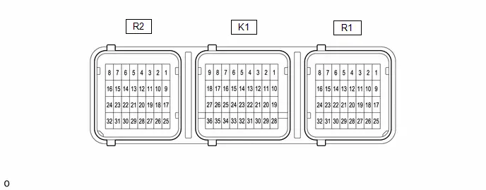
| Terminal No. | Terminal Symbol | Destination |
|---|---|---|
| K1-32 | E2 | Ground |
| K1-33 | E1 | |
| K1-34 | P-AB | Passenger airbag ON/OFF indicator (Map light assembly) |
| K1-35 | PAON | |
| K1-36 | IGR | A/BAG-IGR fuse |
| R1-18 | GNDR | Passenger seat buckle switch (Front seat inner belt assembly RH) |
| R1-27 | RBE | |
| R1-24 | SVC | Occupant classification sensor (Front seat adjuster assembly RH) |
| R1-31 | SGD | |
| R1-32 | SIG |
Freeze Frame Data
FREEZE FRAME DATA
DESCRIPTION
(a) When an occupant classification system DTC is stored, the airbag ECU assembly stores the current vehicle (ECU or sensor) state as Freeze Frame Data.
CHECK FREEZE FRAME DATA
(a) Select a DTC to display the freeze frame data.
Body Electrical > SRS Airbag > Trouble Codes(b) Check the freeze frame data for the output DTC.
CHECK FREEZE FRAME DATA
(a) Read the freeze frame data recorded when the DTC was stored.
Body Electrical > SRS Airbag| Tester Display | Measurement Item | Range | Normal Condition | Diagnostic Note |
|---|---|---|---|---|
| Total Distance Traveled | - | - | - | Not applicable |
| Total Distance Traveled - Unit | - | - | - | Not applicable |
| Load Sensor Total Load Value Information | Total weight information | -606.952 to 838.088 kg | Current value displayed | - |
| Front Inner Load Sensor Load Value Information | Front left sensor weight information | -151.738 to 209.522 kg | Current value displayed | - |
| Rear Inner Load Sensor Load Value Information | Rear left sensor weight information | -151.738 to 209.522 kg | Current value displayed | - |
| Judgment Result for Occupant Detection System (Occupant of Passenger Seat) | Front passenger classification | Unknown, Nothing, Child, Prohibition, Male or Female | Nothing: Seat is vacant Child: Child is seated Male: Male is seated Female: Female is seated | - |
| Judgment Result for Occupant Detection System (Seat Belt Warning of Passenger Seat) | Passenger detection for seat belt warning system | Not Seating or Seating | Not Seating: Seat is vacant Seating: Seat is occupied | - |
| Judgment Result for Occupant Detection System (Buckle Switch of Passenger Seat) | Front passenger side buckle switch | Unknown, Buckle, Unbuckle or Malfunction | Buckle: Front passenger seat belt is fastened Unbuckle: Front passenger seat belt is not fastened Malfunction: Front passenger seat belt is malfunctioning | - |
Fail-safe Chart
FAIL-SAFE CHART
FAIL-SAFE FUNCTION
(a) The following chart shows the status of the front passenger SRS items and passenger airbag ON/OFF indicator operation under failure condition.
| Passenger Airbag ON/OFF Indicator | Front Passenger SRS Item | ||||
|---|---|---|---|---|---|
| ON Indicator | OFF Indicator | Instrument Panel Passenger Airbag Assembly | Front Seat Airbag Assembly RH | Curtain Shield Airbag Assembly RH | Front Seat Outer Belt Assembly RH |
| OFF | ON | X | ○ | ○ | ○ |
- ○: Deployable
- X: Not deployable
Data List / Active Test
DATA LIST / ACTIVE TEST
DATA LIST
HINT:
Using the GTS to read the Data List allows the values or states of switches, sensors, actuators and other items to be read without removing any parts. This non-intrusive inspection can be very useful because intermittent conditions or signals may be discovered before parts or wiring is disturbed. Reading the Data List information early in troubleshooting is one way to save diagnostic time.
NOTICE:
In the table below, the values listed under "Normal Condition" are reference values. Do not depend solely on these reference values when deciding whether a part is faulty or not.
(a) Read the Data List according to the display on the GTS.
Body Electrical > SRS Airbag > Data List| Tester Display | Measurement Item | Range | Normal Condition | Diagnostic Note |
|---|---|---|---|---|
| Total Distance Traveled | - | - | - | Not applicable |
| Total Distance Traveled - Unit | - | - | - | Not applicable |
| Load Sensor Total Load Value Information | Total weight information | -606.952 to 838.088 kg | Current value displayed | - |
| Front Inner Load Sensor Load Value Information | Front left sensor weight information | -151.738 to 209.522 kg | Current value displayed | - |
| Rear Inner Load Sensor Load Value Information | Rear left sensor weight information | -151.738 to 209.522 kg | Current value displayed | - |
| Judgment Result for Occupant Detection System (Occupant of Passenger Seat) | Front passenger classification | Unknown, Nothing, Child, Prohibition, Male or Female | Nothing: Seat is vacant Child: Child is seated Male: Male is seated Female: Female is seated | - |
| Judgment Result for Occupant Detection System (Seat Belt Warning of Passenger Seat) | Passenger detection for seat belt warning system | Not Seating or Seating | Not Seating: Seat is vacant Seating: Seat is occupied | - |
| Judgment Result for Occupant Detection System (Buckle Switch of Passenger Seat) | Front passenger side buckle switch | Unknown, Buckle, Unbuckle or Malfunction | Buckle: Front passenger seat belt is fastened Unbuckle: Front passenger seat belt is not fastened Malfunction: Front passenger seat belt is malfunctioning | - |
| Seat Factory Zero Point Learning History (Front Inner Load Sensor Learning Executed/Unexecuted) | - | - | - | Not applicable |
| Seat Factory Zero Point Learning History (Front Inner Load Sensor Learning Value) | - | - | - | Not applicable |
| Seat Factory Zero Point Learning History (Rear Inner Load Sensor Learning Executed/Unexecuted) | - | - | - | Not applicable |
| Seat Factory Zero Point Learning History (Rear Inner Load Sensor Learning Value) | - | - | - | Not applicable |
| Toyota Prius Vehicle Plant Zero Point Learning History (Front Inner Load Sensor Learning Executed/Unexecuted) | - | - | - | Not applicable |
| Toyota Prius Vehicle Plant Zero Point Learning History (Front Inner Load Sensor Learning Value) | - | - | - | Not applicable |
| Toyota Prius Vehicle Plant Zero Point Learning History (Rear Inner Load Sensor Learning Executed/Unexecuted) | - | - | - | Not applicable |
| Toyota Prius Vehicle Plant Zero Point Learning History (Rear Inner Load Sensor Learning Value) | - | - | - | Not applicable |
| Dealer Zero Point Learning History (Front Inner Load Sensor Learning Executed/Unexecuted) | - | - | - | Not applicable |
| Dealer Zero Point Learning History (Front Inner Load Sensor Learning Value) | - | - | - | Not applicable |
| Dealer Zero Point Learning History (Rear Inner Load Sensor Learning Executed/Unexecuted) | - | - | - | Not applicable |
| Dealer Zero Point Learning History (Rear Inner Load Sensor Learning Value) | - | - | - | Not applicable |
| Front Inner Load Sensor Serial No. - Production Year (Last Two Digits of the Year) | - | - | - | Not applicable |
| Front Inner Load Sensor Serial No. - Production Month | - | - | - | Not applicable |
| Front Inner Load Sensor Serial No. - Production Date | - | - | - | Not applicable |
| Front Inner Load Sensor Serial No. - Sensor No. | - | - | - | Not applicable |
| Front Inner Load Sensor Serial No. - Line No. | - | - | - | Not applicable |
| Front Inner Load Sensor Serial No. - Serial No. | - | - | - | Not applicable |
| Rear Inner Load Sensor Serial No. - Production Year (Last Two Digits of the Year) | - | - | - | Not applicable |
| Rear Inner Load Sensor Serial No. - Production Month | - | - | - | Not applicable |
| Rear Inner Load Sensor Serial No. - Production Date | - | - | - | Not applicable |
| Rear Inner Load Sensor Serial No. - Sensor No. | - | - | - | Not applicable |
| Rear Inner Load Sensor Serial No. - Line No. | - | - | - | Not applicable |
| Rear Inner Load Sensor Serial No. - Serial No. | - | - | - | Not applicable |
Diagnostic Trouble Code Chart
DIAGNOSTIC TROUBLE CODE CHART
Occupant Classification System| DTC No. | Detection Item | DTC Output from | Priority | Link |
|---|---|---|---|---|
| B00C028 | Passenger Seat Occupant Classification Sensor "A" Signal Bias Level Out of Range / Zero Adjustment Failure | SRS Airbag | A |
|
| B00C086 | Passenger Seat Occupant Classification Sensor "A" Signal (some circuit quantity, reported via serial data) Invalid | SRS Airbag | A |
|
| B00C087 | Passenger Seat Occupant Classification Sensor "A" Missing Message | SRS Airbag | A |
|
| B00C096 | Passenger Seat Occupant Classification Sensor "A" Component Internal Failure | SRS Airbag | A |
|
| B00C228 | Passenger Seat Occupant Classification Sensor "C" Signal Bias Level Out of Range / Zero Adjustment Failure | SRS Airbag | A |
|
| B00C286 | Passenger Seat Occupant Classification Sensor "C" Signal (some circuit quantity, reported via serial data) Invalid | SRS Airbag | A |
|
| B00C287 | Passenger Seat Occupant Classification Sensor "C" Missing Message | SRS Airbag | A |
|
| B00C296 | Passenger Seat Occupant Classification Sensor "C" Component Internal Failure | SRS Airbag | A |
|
| B179312 | Load Sensor for Occupant Detection System Circuit Short to Battery | SRS Airbag | A |
|
| B179316 | Load Sensor for Occupant Detection System Circuit Voltage Below Threshold | SRS Airbag | A |
|
| B179317 | Load Sensor for Occupant Detection System Circuit Voltage Above Threshold | SRS Airbag | A |
|


VEHICLE CONTROL HISTORY (RoB)
VEHICLE CONTROL HISTORY (RoB)
NOTICE:
When checking the vehicle control history, make sure to record the output histories. Then, remove the histories and recheck the output histories again.
CHECK VEHICLE CONTROL HISTORY
(a) According to the display on the GTS, check the Toyota Prius Vehicle Control History (RoB).
Body Electrical > SRS Airbag > Utility| Tester Display |
|---|
| Vehicle Control History (RoB) |
| Warning Light | Code | Tester Display | Measurement Item | Diagnostic Note |
|---|---|---|---|---|
| SRS warning light illuminated | X204A | Acceleration Sensor Malfunction | Recorded when airbag ECU assembly received a malfunction signal of accelerator sensor output from skid control ECU. | Refer to How to Proceed with Troubleshooting in Electronically Controlled Brake System.
|
| SRS warning light illuminated | X20AF | Guess Toyota Prius Vehicle Speed Malfunction | Recorded when an estimated vehicle speed flag malfunction signal (invalid value) is received from the skid control ECU. | Refer to How to Proceed with Troubleshooting in Electronically Controlled Brake System.
|
| SRS warning light illuminated | X20D0 | Zero Point Calibration of Occupant Detection Load Sensor Undone | Recorded when occupant classification zero point calibration is not performed or could not be completed normally. |
|
| SRS warning light illuminated | X210B | SRS Airbag ECU IG Voltage Drop | Recorded when the IGR terminal input voltage is continuously less than 8 V for 60 seconds. |
|


CLEAR Toyota Prius Vehicle CONTROL HISTORY
(a) According to the display on the GTS, clear the Vehicle Control History (RoB).
Body Electrical > SRS Airbag > Utility| Tester Display |
|---|
| Toyota Prius Vehicle Control History (RoB) |
Passenger Seat Occupant Classification Sensor "A" Signal Bias Level Out of Range / Zero Adjustment Failure (B00C028)
DESCRIPTION
| DTC No. | Detection Item | DTC Detection Condition | Trouble Area | DTC Output from | Priority |
|---|---|---|---|---|---|
| B00C028 | Passenger Seat Occupant Classification Sensor "A" Signal Bias Level Out of Range / Zero Adjustment Failure | Either of following conditions is met:
| Front seat adjuster assembly RH (front occupant classification sensor LH) | SRS Airbag | A |
CAUTION / NOTICE / HINT
NOTICE:
-
After the ignition switch is turned off, there may be a waiting time before disconnecting the negative (-) auxiliary battery terminal.
Click here

HINT:
When disconnecting and reconnecting the auxiliary battery, there is an automatic learning function that completes learning when the respective system is used.
Click here


-
After replacing the front seat adjuster assembly RH, refer to work procedure.
Click here


PROCEDURE
| 1. | PERFORM ZERO POINT CALIBRATION |
(a) Using the GTS, perform "Occupant Detection Sensor Zero Point Calibration".
HINT:
Click here

|

| 2. | CLEAR DTC |
Pre-procedure1
(a) Turn the ignition switch to ON, and wait for at least 60 seconds.
Procedure1
(b) Clear the DTCs stored in memory.
Body Electrical > SRS Airbag > Clear DTCsPost-procedure1
(c) Turn the ignition switch off.
|

| 3. | CHECK DTC |
Pre-procedure1
(a) Turn the ignition switch to ON, and wait for at least 60 seconds.
Procedure1
(b) Check the DTCs.
Body Electrical > SRS Airbag > Trouble Codes| Result | Proceed to |
|---|---|
| B00C028 is output | A |
| B00C028 is not output | B |
Post-procedure1
(c) None
| B |

| END (NORMAL AFTER PERFORMING ZERO POINT CALIBRATION) |
|

| 4. | REPLACE FRONT SEAT ADJUSTER ASSEMBLY RH |
Pre-procedure1
(a) Turn the ignition switch off.
(b) Disconnect the cable from the negative (-) auxiliary battery terminal, and wait for at least 60 seconds.
Procedure1
(c) Replace the front seat adjuster assembly RH with a new one.
HINT:
Click here


Post-procedure1
(d) Connect the cable to the negative (-) auxiliary battery terminal, and wait for at least 2 seconds.
|

| 5. | PERFORM ZERO POINT CALIBRATION |
(a) Using the GTS, perform "Occupant Detection Sensor Zero Point Calibration".
HINT:
Click here

| NEXT |

| END (FRONT SEAT ADJUSTER ASSEMBLY RH WAS DEFECTIVE) |
Passenger Seat Occupant Classification Sensor "A" Signal (some circuit quantity, reported via serial data) Invalid (B00C086)
DESCRIPTION
| DTC No. | Detection Item | DTC Detection Condition | Trouble Area | DTC Output from | Priority |
|---|---|---|---|---|---|
| B00C086 | Passenger Seat Occupant Classification Sensor "A" Signal (some circuit quantity, reported via serial data) Invalid | Either of following conditions is met:
|
| SRS Airbag | A |
WIRING DIAGRAM

CAUTION / NOTICE / HINT
NOTICE:
-
After the ignition switch is turned off, there may be a waiting time before disconnecting the negative (-) auxiliary battery terminal.
Click here

HINT:
When disconnecting and reconnecting the auxiliary battery, there is an automatic learning function that completes learning when the respective system is used.
Click here


-
After replacing the airbag ECU assembly or front seat adjuster assembly RH, refer to work procedure.
Click here


HINT:
- If it is difficult to perform troubleshooting (wire harness inspection), remove the front passenger seat installation bolts to see under the seat cushion.
- In the above case, lift and hold the seat so that it does not fall down. Hold the seat only as necessary because holding the seat for a long period of time may cause seat rail deformation.
PROCEDURE
| 1. | CHECK DTC |
(a) Check the DTCs.
Body Electrical > SRS Airbag > Trouble Codes| Result | Proceed to |
|---|---|
| B00C086 is output | A |
| B00C286 is output | B |
| B00C086 and B00C286 are output | C |
| B00C086 and B00C286 are not output | D |
HINT:
Codes other than DTCs B00C086 and B00C286 may be output at this time, but they are not related to this check.
| B |

| GO TO STEP 5 |
| C |

| GO TO STEP 8 |
| D |

| USE SIMULATION METHOD TO CHECK |
|

| 2. | CHECK CONNECTION OF CONNECTORS |
Pre-procedure1
(a) Turn the ignition switch off.
(b) Disconnect the cable from the negative (-) auxiliary battery terminal, and wait for at least 60 seconds.
Procedure1
(c) Check that the connectors are properly connected to the airbag ECU assembly and front seat adjuster assembly RH (front occupant classification sensor LH).
OK:
The connectors are properly connected.
Post-procedure1
(d) None
| NG |

| CONNECT CONNECTORS PROPERLY |
|

| 3. | CHECK CONNECTORS |
Pre-procedure1
| (a) Disconnect the airbag ECU assembly connector. |
|

(b) Disconnect the front seat adjuster assembly RH (front occupant classification sensor LH) connector.
Procedure1
(c) Check that the terminals of the connectors are not deformed or damaged.
OK:
The terminals are not deformed or damaged.
Post-procedure1
(d) None
| NG |

| REPAIR OR REPLACE HARNESS OR CONNECTOR |
|

| 4. | CHECK HARNESS AND CONNECTOR (AIRBAG ECU ASSEMBLY - FRONT SEAT ADJUSTER ASSEMBLY RH) |
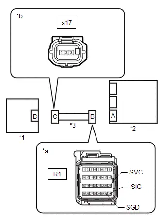
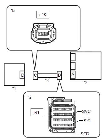
| (a) Measure the resistance according to the value(s) in the table below. Standard Resistance:  Click Location & Routing(R1,a17) Click Connector(R1) Click Connector(a17) Click Location & Routing(R1,a17) Click Connector(R1) Click Connector(a17)
|
|

| OK |

| REPLACE FRONT SEAT ADJUSTER ASSEMBLY RH
|


| NG |

| REPAIR OR REPLACE HARNESS OR CONNECTOR |
| 5. | CHECK CONNECTION OF CONNECTORS |
Pre-procedure1
(a) Turn the ignition switch off.
(b) Disconnect the cable from the negative (-) auxiliary battery terminal, and wait for at least 60 seconds.
Procedure1
(c) Check that the connectors are properly connected to the airbag ECU assembly and front seat adjuster assembly RH (rear occupant classification sensor LH).
OK:
The connectors are properly connected.
Post-procedure1
(d) None
| NG |

| CONNECT CONNECTORS PROPERLY |
|

| 6. | CHECK CONNECTORS |
Pre-procedure1
| (a) Disconnect the airbag ECU assembly connector. |
|
(b) Disconnect the front seat adjuster assembly RH (rear occupant classification sensor LH) connector.
Procedure1
(c) Check that the terminals of the connectors are not deformed or damaged.
OK:
The terminals are not deformed or damaged.
Post-procedure1
(d) None
| NG |

| REPAIR OR REPLACE HARNESS OR CONNECTOR |
|

| 7. | CHECK HARNESS AND CONNECTOR (AIRBAG ECU ASSEMBLY - FRONT SEAT ADJUSTER ASSEMBLY RH) |
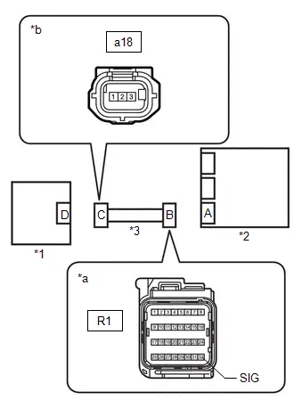
| (a) Measure the resistance according to the value(s) in the table below. Standard Resistance:  Click Location & Routing(R1,a18) Click Connector(R1) Click Connector(a18) Click Location & Routing(R1,a18) Click Connector(R1) Click Connector(a18)
|
|
| OK |

| REPLACE FRONT SEAT ADJUSTER ASSEMBLY RH
|


| NG |

| REPAIR OR REPLACE HARNESS OR CONNECTOR |
| 8. | CHECK CONNECTION OF CONNECTORS |
Pre-procedure1
(a) Turn the ignition switch off.
(b) Disconnect the cable from the negative (-) auxiliary battery terminal, and wait for at least 60 seconds.
Procedure1
(c) Check that the connectors are properly connected to the airbag ECU assembly and front seat adjuster assembly RH.
OK:
The connectors are properly connected.
Post-procedure1
(d) None
| NG |

| CONNECT CONNECTORS PROPERLY |
|

| 9. | CHECK CONNECTORS |
Pre-procedure1
| (a) Disconnect the airbag ECU assembly connector. |
|

(b) Disconnect the front seat adjuster assembly RH connector.
Procedure1
(c) Check that the terminals of the connectors are not deformed or damaged.
OK:
The terminals are not deformed or damaged.
Post-procedure1
(d) None
| NG |

| REPAIR OR REPLACE HARNESS OR CONNECTOR |
|

| 10. | CHECK HARNESS AND CONNECTOR (AIRBAG ECU ASSEMBLY - FRONT SEAT ADJUSTER ASSEMBLY RH) |
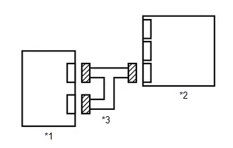
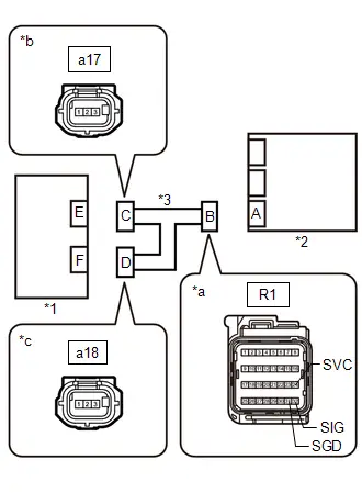
| (a) Measure the resistance according to the value(s) in the table below. Standard Resistance:  Click Location & Routing(R1,a17,a18) Click Connector(R1) Click Connector(a17) Click Connector(a18) Click Location & Routing(R1,a17,a18) Click Connector(R1) Click Connector(a17) Click Connector(a18)
|
|

| NG |

| REPAIR OR REPLACE HARNESS OR CONNECTOR |
|

| 11. | CHECK HARNESS AND CONNECTOR (AIRBAG ECU ASSEMBLY - FRONT SEAT ADJUSTER ASSEMBLY RH) |
| (a) Measure the resistance according to the value(s) in the table below. Standard Resistance:  Click Location & Routing(R1,a17,a18) Click Connector(R1) Click Connector(a17) Click Connector(a18) Click Location & Routing(R1,a17,a18) Click Connector(R1) Click Connector(a17) Click Connector(a18)
|
|

| NG |

| REPAIR OR REPLACE HARNESS OR CONNECTOR |
|

| 12. | CHECK HARNESS AND CONNECTOR (AIRBAG ECU ASSEMBLY - FRONT SEAT ADJUSTER ASSEMBLY RH) |
Pre-procedure1
(a) Connect the cable to the negative (-) auxiliary battery terminal, and wait for at least 2 seconds.
(b) Turn the ignition switch to ON.
Procedure1
| (c) Measure the voltage according to the value(s) in the table below. Standard Voltage:  Click Location & Routing(R1,a17,a18) Click Connector(R1) Click Connector(a17) Click Connector(a18) Click Location & Routing(R1,a17,a18) Click Connector(R1) Click Connector(a17) Click Connector(a18)
Result:
|
|

Post-procedure1
(d) None
| OK |

| REPLACE AIRBAG ECU ASSEMBLY
|


| NG |

| REPAIR OR REPLACE HARNESS OR CONNECTOR |
Passenger Seat Occupant Classification Sensor "A" Missing Message (B00C087)
DESCRIPTION
| DTC No. | Detection Item | DTC Detection Condition | Trouble Area | DTC Output from | Priority |
|---|---|---|---|---|---|
| B00C087 | Passenger Seat Occupant Classification Sensor "A" Missing Message | Either of following conditions is met:
|
| SRS Airbag | A |
WIRING DIAGRAM
CAUTION / NOTICE / HINT
NOTICE:
-
After the ignition switch is turned off, there may be a waiting time before disconnecting the negative (-) auxiliary battery terminal.
Click here

HINT:
When disconnecting and reconnecting the auxiliary battery, there is an automatic learning function that completes learning when the respective system is used.
Click here


-
After replacing the airbag ECU assembly or front seat adjuster assembly RH, refer to work procedure.
Click here


HINT:
- If it is difficult to perform troubleshooting (wire harness inspection), remove the front passenger seat installation bolts to see under the seat cushion.
- In the above case, lift and hold the seat so that it does not fall down. Hold the seat only as necessary because holding the seat for a long period of time may cause seat rail deformation.
PROCEDURE
| 1. | CHECK DTC |
(a) Check the DTCs.
Body Electrical > SRS Airbag > Trouble Codes| Result | Proceed to |
|---|---|
| B00C087 is output | A |
| B00C287 is output | B |
| B00C087 and B00C287 are output | C |
| B00C087 and B00C287 are not output | D |
HINT:
Codes other than DTCs B00C087 and B00C287 may be output at this time, but they are not related to this check.
| B |

| GO TO STEP 5 |
| C |

| GO TO STEP 8 |
| D |

| USE SIMULATION METHOD TO CHECK |
|

| 2. | CHECK CONNECTION OF CONNECTORS |
Pre-procedure1
(a) Turn the ignition switch off.
(b) Disconnect the cable from the negative (-) auxiliary battery terminal, and wait for at least 60 seconds.
Procedure1
(c) Check that the connectors are properly connected to the airbag ECU assembly and front seat adjuster assembly RH (front occupant classification sensor LH).
OK:
The connectors are properly connected.
Post-procedure1
(d) None
| NG |

| CONNECT CONNECTORS PROPERLY |
|

| 3. | CHECK CONNECTORS |
Pre-procedure1
| (a) Disconnect the airbag ECU assembly connector. |
|

(b) Disconnect the front seat adjuster assembly RH (front occupant classification sensor LH) connector.
Procedure1
(c) Check that the terminals of the connectors are not deformed or damaged.
OK:
The terminals are not deformed or damaged.
Post-procedure1
(d) None
| NG |

| REPAIR OR REPLACE HARNESS OR CONNECTOR |
|

| 4. | CHECK HARNESS AND CONNECTOR (AIRBAG ECU ASSEMBLY - FRONT SEAT ADJUSTER ASSEMBLY RH) |
| (a) Measure the resistance according to the value(s) in the table below. Standard Resistance:  Click Location & Routing(R1,a17) Click Connector(R1) Click Connector(a17) Click Location & Routing(R1,a17) Click Connector(R1) Click Connector(a17)
|
|
| OK |

| REPLACE FRONT SEAT ADJUSTER ASSEMBLY RH
|


| NG |

| REPAIR OR REPLACE HARNESS OR CONNECTOR |
| 5. | CHECK CONNECTION OF CONNECTORS |
Pre-procedure1
(a) Turn the ignition switch off.
(b) Disconnect the cable from the negative (-) auxiliary battery terminal, and wait for at least 60 seconds.
Procedure1
(c) Check that the connectors are properly connected to the airbag ECU assembly and front seat adjuster assembly RH (rear occupant classification sensor LH).
OK:
The connectors are properly connected.
Post-procedure1
(d) None
| NG |

| CONNECT CONNECTORS PROPERLY |
|

| 6. | CHECK CONNECTORS |
Pre-procedure1
| (a) Disconnect the airbag ECU assembly connector. |
|

(b) Disconnect the front seat adjuster assembly RH (rear occupant classification sensor LH) connector.
Procedure1
(c) Check that the terminals of the connectors are not deformed or damaged.
OK:
The terminals are not deformed or damaged.
Post-procedure1
(d) None
| NG |

| REPAIR OR REPLACE HARNESS OR CONNECTOR |
|

| 7. | CHECK HARNESS AND CONNECTOR (AIRBAG ECU ASSEMBLY - FRONT SEAT ADJUSTER ASSEMBLY RH) |
| (a) Measure the resistance according to the value(s) in the table below. Standard Resistance:  Click Location & Routing(R1,a18) Click Connector(R1) Click Connector(a18) Click Location & Routing(R1,a18) Click Connector(R1) Click Connector(a18)
|
|

| OK |

| REPLACE FRONT SEAT ADJUSTER ASSEMBLY RH
|


| NG |

| REPAIR OR REPLACE HARNESS OR CONNECTOR |
| 8. | CHECK CONNECTION OF CONNECTORS |
Pre-procedure1
(a) Turn the ignition switch off.
(b) Disconnect the cable from the negative (-) auxiliary battery terminal, and wait for at least 60 seconds.
Procedure1
(c) Check that the connectors are properly connected to the airbag ECU assembly and front seat adjuster assembly RH.
OK:
The connectors are properly connected.
Post-procedure1
(d) None
| NG |

| CONNECT CONNECTORS PROPERLY |
|

| 9. | CHECK CONNECTORS |
Pre-procedure1
| (a) Disconnect the airbag ECU assembly connector. |
|
(b) Disconnect the front seat adjuster assembly RH connector.
Procedure1
(c) Check that the terminals of the connectors are not deformed or damaged.
OK:
The terminals are not deformed or damaged.
Post-procedure1
(d) None
| NG |

| REPAIR OR REPLACE HARNESS OR CONNECTOR |
|

| 10. | CHECK HARNESS AND CONNECTOR (AIRBAG ECU ASSEMBLY - FRONT SEAT ADJUSTER ASSEMBLY RH) |
| (a) Measure the resistance according to the value(s) in the table below. Standard Resistance:  Click Location & Routing(R1,a17,a18) Click Connector(R1) Click Connector(a17) Click Connector(a18) Click Location & Routing(R1,a17,a18) Click Connector(R1) Click Connector(a17) Click Connector(a18)
|
|

| OK |

| REPLACE AIRBAG ECU ASSEMBLY
|


| NG |

| REPAIR OR REPLACE HARNESS OR CONNECTOR |
Passenger Seat Occupant Classification Sensor "A" Component Internal Failure (B00C096)
DESCRIPTION
| DTC No. | Detection Item | DTC Detection Condition | Trouble Area | DTC Output from | Priority |
|---|---|---|---|---|---|
| B00C096 | Passenger Seat Occupant Classification Sensor "A" Component Internal Failure | Front occupant classification sensor LH malfunction | Front seat adjuster assembly RH (front occupant classification sensor LH) | SRS Airbag | A |
CAUTION / NOTICE / HINT
NOTICE:
After replacing the front seat adjuster assembly RH, refer to work procedure.
Click here


PROCEDURE
| 1. | CLEAR DTC |
Pre-procedure1
(a) Turn the ignition switch to ON, and wait for at least 60 seconds.
Procedure1
(b) Clear the DTCs stored in memory.
Body Electrical > SRS Airbag > Clear DTCsPost-procedure1
(c) Turn the ignition switch off.
|

| 2. | CHECK DTC |
Pre-procedure1
(a) Turn the ignition switch to ON, and wait for at least 60 seconds.
Procedure1
(b) Check the DTCs.
Body Electrical > SRS Airbag > Trouble Codes| Result | Proceed to |
|---|---|
| B00C096 is output | A |
| B00C096 is not output | B |
Post-procedure1
(c) None
| A |

| REPLACE FRONT SEAT ADJUSTER ASSEMBLY RH
|


| B |

| USE SIMULATION METHOD TO CHECK |
Load Sensor for Occupant Detection System Circuit Short to Battery (B179312)
DESCRIPTION
| DTC No. | Detection Item | DTC Detection Condition | Trouble Area | DTC Output from | Priority |
|---|---|---|---|---|---|
| B179312 | Load Sensor for Occupant Detection System Circuit Short to Battery | When the detections voltage higher than specified value before supplying power to the sensor. |
| SRS Airbag | A |
WIRING DIAGRAM

CAUTION / NOTICE / HINT
NOTICE:
-
After the ignition switch is turned off, there may be a waiting time before disconnecting the negative (-) auxiliary battery terminal.
Click here

HINT:
When disconnecting and reconnecting the auxiliary battery, there is an automatic learning function that completes learning when the respective system is used.
Click here


-
After replacing the airbag ECU assembly, refer to work procedure.
Click here


HINT:
- If it is difficult to perform troubleshooting (wire harness inspection), remove the front passenger seat installation bolts to see under the seat cushion.
- In the above case, lift and hold the seat so that it does not fall down. Hold the seat only as necessary because holding the seat for a long period of time may cause seat rail deformation.
PROCEDURE
| 1. | CHECK CONNECTION OF CONNECTORS |
Pre-procedure1
(a) Turn the ignition switch off.
(b) Disconnect the cable from the negative (-) auxiliary battery terminal, and wait for at least 60 seconds.
Procedure1
(c) Check that the connectors are properly connected to the airbag ECU assembly and front seat adjuster assembly RH.
OK:
The connectors are properly connected.
Post-procedure1
(d) None
| NG |

| CONNECT CONNECTORS PROPERLY |
|

| 2. | CHECK CONNECTORS |
Pre-procedure1
| (a) Disconnect the airbag ECU assembly connector. |
|

(b) Disconnect the front seat adjuster assembly RH connector.
Procedure1
(c) Check that the terminals of the connectors are not deformed or damaged.
OK:
The terminals are not deformed or damaged.
Post-procedure1
(d) None
| NG |

| REPAIR OR REPLACE HARNESS OR CONNECTOR |
|

| 3. | CHECK HARNESS AND CONNECTOR (AIRBAG ECU ASSEMBLY - FRONT SEAT ADJUSTER ASSEMBLY RH) |
Pre-procedure1
(a) Connect the cable to the negative (-) auxiliary battery terminal, and wait for at least 2 seconds.
(b) Turn the ignition switch to ON.
Procedure1
| (c) Measure the voltage according to the value(s) in the table below. Standard Voltage:  Click Location & Routing(R1,a17,a18) Click Connector(R1) Click Connector(a17) Click Connector(a18) Click Location & Routing(R1,a17,a18) Click Connector(R1) Click Connector(a17) Click Connector(a18)
Result:
|
|

Post-procedure1
(d) None
| OK |

| REPLACE AIRBAG ECU ASSEMBLY
|


| NG |

| REPAIR OR REPLACE HARNESS OR CONNECTOR |
Load Sensor for Occupant Detection System Circuit Voltage Below Threshold (B179316)
DESCRIPTION
| DTC No. | Detection Item | DTC Detection Condition | Trouble Area | DTC Output from | Priority |
|---|---|---|---|---|---|
| B179316 | Load Sensor for Occupant Detection System Circuit Voltage Below Threshold | When the detections voltage value below specified value before supplying power to the sensor. |
| SRS Airbag | A |
WIRING DIAGRAM

CAUTION / NOTICE / HINT
NOTICE:
-
After the ignition switch is turned off, there may be a waiting time before disconnecting the negative (-) auxiliary battery terminal.
Click here

HINT:
When disconnecting and reconnecting the auxiliary battery, there is an automatic learning function that completes learning when the respective system is used.
Click here


-
After replacing the airbag ECU assembly or front seat adjuster assembly RH, refer to work procedure.
Click here


- Inspect the fuses for circuits related to this system before performing the following procedure.
HINT:
- If it is difficult to perform troubleshooting (wire harness inspection), remove the front passenger seat installation bolts to see under the seat cushion.
- In the above case, lift and hold the seat so that it does not fall down. Hold the seat only as necessary because holding the seat for a long period of time may cause seat rail deformation.
PROCEDURE
| 1. | CHECK CONNECTION OF CONNECTORS |
Pre-procedure1
(a) Turn the ignition switch off.
(b) Disconnect the cable from the negative (-) auxiliary battery terminal, and wait for at least 60 seconds.
Procedure1
(c) Check that the connectors are properly connected to the airbag ECU assembly and front seat adjuster assembly RH.
OK:
The connectors are properly connected.
Post-procedure1
(d) None
| NG |

| CONNECT CONNECTORS PROPERLY |
|

| 2. | CHECK CONNECTORS |
Pre-procedure1
| (a) Disconnect the airbag ECU assembly connector. |
|

(b) Disconnect the front seat adjuster assembly RH connector.
Procedure1
(c) Check that the terminals of the connectors are not deformed or damaged.
OK:
The terminals are not deformed or damaged.
Post-procedure1
(d) None
| NG |

| REPAIR OR REPLACE HARNESS OR CONNECTOR |
|

| 3. | CHECK HARNESS AND CONNECTOR (AIRBAG ECU ASSEMBLY - AUXILIARY BATTERY) |
Pre-procedure1
(a) Disconnect the airbag ECU assembly connector.
(b) Connect the cable to the negative (-) auxiliary battery terminal, and wait for at least 2 seconds.
(c) Turn the ignition switch to ON.
(d) Operate all components of the electrical systems (defogger, wipers, headlights, heater blower, etc.).
Procedure1
| (e) Measure the voltage according to the value(s) in the table below. Standard Voltage:  Click Location & Routing(K1) Click Connector(K1) Click Location & Routing(K1) Click Connector(K1)
Result:
|
|

Post-procedure1
(f) Turn the ignition switch off.
(g) Disconnect the cable from the negative (-) auxiliary battery terminal, and wait for at least 60 seconds.
| NG |

| REPAIR OR REPLACE HARNESS OR CONNECTOR |
|

| 4. | CHECK HARNESS AND CONNECTOR (AIRBAG ECU ASSEMBLY - FRONT SEAT ADJUSTER ASSEMBLY RH) |
| (a) Measure the resistance according to the value(s) in the table below. Standard Resistance:  Click Location & Routing(R1,a17,a18) Click Connector(R1) Click Connector(a17) Click Connector(a18) Click Location & Routing(R1,a17,a18) Click Connector(R1) Click Connector(a17) Click Connector(a18)
|
|

| NG |

| REPAIR OR REPLACE HARNESS OR CONNECTOR |
|

| 5. | CHECK AIRBAG ECU ASSEMBLY |
Pre-procedure1
(a) Connect the connector to the airbag ECU assembly.
(b) Connect the cable to the negative (-) auxiliary battery terminal, and wait for at least 2 seconds.
(c) Turn the ignition switch to ON.
Procedure1
| (d) Measure the voltage according to the value(s) in the table below. Standard Voltage:  Click Location & Routing(a17,a18) Click Connector(a17) Click Connector(a18) Click Location & Routing(a17,a18) Click Connector(a17) Click Connector(a18)
Result:
|
|

Post-procedure1
(e) None
| OK |

| REPLACE FRONT SEAT ADJUSTER ASSEMBLY RH
|


| NG |

| REPLACE AIRBAG ECU ASSEMBLY
|


Trouble in Passenger Airbag ON/OFF Indicator
DESCRIPTION
The occupant classification system detects the front passenger seat condition. It then displays the instrument panel passenger airbag assembly condition (activated/not activated) using the passenger airbag ON/OFF indicator.
HINT:
Approximately 6 seconds after the ignition switch is turned to ON, the passenger airbag ON/OFF indicator will indicate ON/OFF depending on the following conditions.
Indicator Operation| Front Passenger Seat Condition | Passenger Airbag ON/OFF Indicator | SRS Warning Light | |
|---|---|---|---|
| ON Indicator | OFF Indicator | ||
| Vacant | OFF | ON | OFF |
| Adult*1 is seated | ON | OFF | OFF |
| Child*2 is seated | ON or OFF*2 | OFF or ON*2 | OFF |
| Child restraint system is installed | OFF | ON | OFF |
| Occupant classification system failure | OFF | ON | ON |
- *1: The system judges a person of average adult weight or more as an adult. If a smaller adult sits in the front passenger seat, the system may not recognize them as an adult depending on their physique and posture.
- *2: The system may not recognize a child or a child in a child restraint system as a child depending on factors such as the positioning of the child restraint system or the child's physique or posture.
CAUTION / NOTICE / HINT
NOTICE:
-
After the ignition switch is turned off, there may be a waiting time before disconnecting the negative (-) auxiliary battery terminal.
Click here

HINT:
When disconnecting and reconnecting the auxiliary battery, there is an automatic learning function that completes learning when the respective system is used.
Click here


-
After replacing the airbag ECU assembly, refer to work procedure.
Click here


PROCEDURE
| 1. | CHECK SRS WARNING LIGHT |
(a) Turn the ignition switch to ON, and check the SRS warning light condition.
OK:
After the primary check period, the SRS warning light goes off.
HINT:
The primary check is performed for approximately 6 seconds after the ignition switch is turned to ON.
| NG |

| GO TO AIRBAG SYSTEM
|


|

| 2. | PERFORM ZERO POINT CALIBRATION |
(a) Using the GTS, perform "Occupant Detection Sensor Zero Point Calibration".
Click here

|

| 3. | CHECK PASSENGER AIRBAG ON/OFF INDICATOR |
(a) Check the passenger airbag ON/OFF indicator.
Click here

OK:
Passenger airbag ON/OFF indicator operation normally.
| OK |

| END (NORMAL AFTER PERFORMING ZERO POINT CALIBRATION) |
|

| 4. | RETIGHTEN FRONT SEAT ASSEMBLY RH BOLT |
(a) Loosen the 4 installation bolts of the front seat assembly RH.
(b) Tighten the 4 installation bolts of the front seat assembly RH to the specified torque.
Click here

|

| 5. | PERFORM ZERO POINT CALIBRATION |
(a) Using the GTS, perform "Occupant Detection Sensor Zero Point Calibration".
Click here

|

| 6. | CHECK PASSENGER AIRBAG ON/OFF INDICATOR |
(a) Check the passenger airbag ON/OFF indicator.
Click here

OK:
Passenger airbag ON/OFF indicator operation normally.
| OK |

| END (THE 4 INSTALLATION BOLTS WAS LOOSEN) |
|

| 7. | READ VALUE USING GTS |
(a) Read the Data List according to the display on the GTS.
Body Electrical > SRS Airbag > Data List| Tester Display | Measurement Item | Range | Normal Condition | Diagnostic Note |
|---|---|---|---|---|
| Judgment Result for Occupant Detection System (Buckle Switch of Passenger Seat) | Front passenger side buckle switch | Unknown, Buckle, Unbuckle or Malfunction | Buckle: Front passenger seat belt is fastened Unbuckle: Front passenger seat belt is not fastened Malfunction: Front passenger seat belt is malfunctioning | - |
| Tester Display |
|---|
| Judgment Result for Occupant Detection System (Buckle Switch of Passenger Seat) |
OK:
The GTS display changes correctly in accordance with the operation of the front passenger side buckle switch.
| NG |

| GO TO STEP 11 |
|

| 8. | CHECK CONNECTORS |
| (a) Turn the ignition switch off. |
|

(b) Disconnect the cable from the negative (-) auxiliary battery terminal, and wait for at least 60 seconds.
(c) Disconnect the airbag ECU assembly connector.
(d) Disconnect the front seat adjuster assembly RH connector.
(e) Check that the terminals of the connectors are not deformed or damaged.
OK:
The terminals are not deformed or damaged.
| NG |

| REPAIR OR REPLACE HARNESS OR CONNECTOR |
|

| 9. | REPLACE AIRBAG ECU ASSEMBLY |
(a) Connect the front seat adjuster assembly RH connector.
(b) Replace the airbag ECU assembly with a new one.
Click here


(c) Connect the cable to the negative (-) auxiliary battery terminal, and wait for at least 2 seconds.
|

| 10. | PERFORM ZERO POINT CALIBRATION |
(a) Using the GTS, perform "Occupant Detection Sensor Zero Point Calibration".
Click here

| NEXT |

| END (AIRBAG ECU ASSEMBLY WAS DEFECTIVE) |
| 11. | CHECK CONNECTORS |
| (a) Turn the ignition switch off. |
|

(b) Disconnect the cable from the negative (-) auxiliary battery terminal, and wait for at least 60 seconds.
(c) Disconnect the airbag ECU assembly connector.
(d) Disconnect the front seat inner belt assembly RH connector.
(e) Check that the terminals of the connectors are not deformed or damaged.
OK:
The terminals are not deformed or damaged.
| NG |

| REPAIR OR REPLACE HARNESS OR CONNECTOR |
|

| 12. | REPLACE FRONT SEAT INNER BELT ASSEMBLY RH |
(a) Connect the airbag ECU assembly connector.
(b) Replace the front seat inner belt assembly RH with a new one.
Click here


(c) Connect the cable to the negative (-) auxiliary battery terminal, and wait for at least 2 seconds.
|

| 13. | PERFORM ZERO POINT CALIBRATION |
(a) Using the GTS, perform "Occupant Detection Sensor Zero Point Calibration".
Click here

| NEXT |

| END (FRONT SEAT INNER BELT ASSEMBLY RH WAS DEFECTIVE) |
LIN Communication Circuit
DESCRIPTION
| Error Code | Detection Item | Detection Condition | Trouble Area |
|---|---|---|---|
| 17 | FI LIN Communication Lost | When a communication malfunction with the load sensor is detected |
|
| 18 | RI LIN Communication Lost | When a communication malfunction with the load sensor is detected |
|
WIRING DIAGRAM

CAUTION / NOTICE / HINT
NOTICE:
-
After the ignition switch is turned off, there may be a waiting time before disconnecting the negative (-) auxiliary battery terminal.
Click here

HINT:
When disconnecting and reconnecting the auxiliary battery, there is an automatic learning function that completes learning when the respective system is used.
Click here


-
After replacing the airbag ECU assembly or front seat adjuster assembly RH, refer to work procedure.
Click here


HINT:
- If it is difficult to perform troubleshooting (wire harness inspection), remove the front passenger seat installation bolts to see under the seat cushion.
- In the above case, lift and hold the seat so that it does not fall down. Hold the seat only as necessary because holding the seat for a long period of time may cause seat rail deformation.
PROCEDURE
| 1. | CHECK ERROR CODE |
(a) Check the Error Code.
| Result | Proceed to |
|---|---|
| Error code 17 is output | A |
| Error code 18 is output | B |
| Error code 17 and 18 are output | C |
| B |

| GO TO STEP 7 |
| C |

| GO TO STEP 12 |
|

| 2. | CHECK CONNECTION OF CONNECTORS |
(a) Turn the ignition switch off.
(b) Disconnect the cable from the negative (-) auxiliary battery terminal, and wait for at least 60 seconds.
(c) Check that the connectors are properly connected to the airbag ECU assembly and front seat adjuster assembly RH (front occupant classification sensor LH).
OK:
The connectors are properly connected.
| NG |

| CONNECT CONNECTORS PROPERLY |
|

| 3. | CHECK CONNECTORS |
| (a) Disconnect the airbag ECU assembly connector. |
|

(b) Disconnect the front seat adjuster assembly RH (front occupant classification sensor LH) connector.
(c) Check that the terminals of the connectors are not deformed or damaged.
OK:
The terminals are not deformed or damaged.
| NG |

| REPAIR OR REPLACE HARNESS OR CONNECTOR |
|

| 4. | CHECK HARNESS AND CONNECTOR (AIRBAG ECU ASSEMBLY - FRONT SEAT ADJUSTER ASSEMBLY RH) |
| (a) Measure the resistance according to the value(s) in the table below. Standard Resistance:  Click Location & Routing(R1,a17) Click Connector(R1) Click Connector(a17) Click Location & Routing(R1,a17) Click Connector(R1) Click Connector(a17)
|
|

| NG |

| REPAIR OR REPLACE HARNESS OR CONNECTOR |
|

| 5. | REPLACE FRONT SEAT ADJUSTER ASSEMBLY RH |
(a) Connect the airbag ECU assembly connector.
(b) Replace the front seat adjuster assembly RH with a new one.
Click here


|

| 6. | PERFORM ZERO POINT CALIBRATION |
(a) Using the GTS, perform "Occupant Detection Sensor Zero Point Calibration".
Click here

| NEXT |

| END |
| 7. | CHECK CONNECTION OF CONNECTORS |
(a) Turn the ignition switch off.
(b) Disconnect the cable from the negative (-) auxiliary battery terminal, and wait for at least 60 seconds.
(c) Check that the connectors are properly connected to the airbag ECU assembly and front seat adjuster assembly RH (rear occupant classification sensor LH).
OK:
The connectors are properly connected.
| NG |

| CONNECT CONNECTORS PROPERLY |
|

| 8. | CHECK CONNECTORS |
| (a) Disconnect the airbag ECU assembly connector. |
|

(b) Disconnect the front seat adjuster assembly RH (rear occupant classification sensor LH) connector.
(c) Check that the terminals of the connectors are not deformed or damaged.
OK:
The terminals are not deformed or damaged.
| NG |

| REPAIR OR REPLACE HARNESS OR CONNECTOR |
|

| 9. | CHECK HARNESS AND CONNECTOR (AIRBAG ECU ASSEMBLY - FRONT SEAT ADJUSTER ASSEMBLY RH) |
| (a) Measure the resistance according to the value(s) in the table below. Standard Resistance:  Click Location & Routing(R1,a18) Click Connector(R1) Click Connector(a18) Click Location & Routing(R1,a18) Click Connector(R1) Click Connector(a18)
|
|
| NG |

| REPAIR OR REPLACE HARNESS OR CONNECTOR |
|

| 10. | REPLACE FRONT SEAT ADJUSTER ASSEMBLY RH |
(a) Connect the airbag ECU assembly connector.
(b) Replace the front seat adjuster assembly RH with a new one.
Click here


|

| 11. | PERFORM ZERO POINT CALIBRATION |
(a) Using the GTS, perform "Occupant Detection Sensor Zero Point Calibration".
Click here

| NEXT |

| END |
| 12. | CHECK CONNECTION OF CONNECTORS |
(a) Turn the ignition switch off.
(b) Disconnect the cable from the negative (-) auxiliary battery terminal, and wait for at least 60 seconds.
(c) Check that the connectors are properly connected to the airbag ECU assembly and front seat adjuster assembly RH.
OK:
The connectors are properly connected.
| NG |

| CONNECT CONNECTORS PROPERLY |
|

| 13. | CHECK CONNECTORS |
| (a) Disconnect the airbag ECU assembly connector. |
|

(b) Disconnect the front seat adjuster assembly RH connector.
(c) Check that the terminals of the connectors are not deformed or damaged.
OK:
The terminals are not deformed or damaged.
| NG |

| REPAIR OR REPLACE HARNESS OR CONNECTOR |
|

| 14. | CHECK HARNESS AND CONNECTOR (AIRBAG ECU ASSEMBLY - FRONT SEAT ADJUSTER ASSEMBLY RH) |
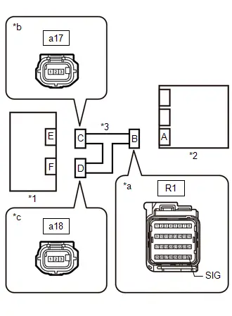
| (a) Measure the resistance according to the value(s) in the table below. Standard Resistance:  Click Location & Routing(R1,a17,a18) Click Connector(R1) Click Connector(a17) Click Connector(a18) Click Location & Routing(R1,a17,a18) Click Connector(R1) Click Connector(a17) Click Connector(a18)
|
|
| NG |

| REPAIR OR REPLACE HARNESS OR CONNECTOR |
|

| 15. | CHECK HARNESS AND CONNECTOR (AIRBAG ECU ASSEMBLY - FRONT SEAT ADJUSTER ASSEMBLY RH) |
| (a) Measure the resistance according to the value(s) in the table below. Standard Resistance:  Click Location & Routing(R1,a17,a18) Click Connector(R1) Click Connector(a17) Click Connector(a18) Click Location & Routing(R1,a17,a18) Click Connector(R1) Click Connector(a17) Click Connector(a18)
|
|

| NG |

| REPAIR OR REPLACE HARNESS OR CONNECTOR |
|

| 16. | CHECK HARNESS AND CONNECTOR (AIRBAG ECU ASSEMBLY - FRONT SEAT ADJUSTER ASSEMBLY RH) |
| (a) Connect the cable to the negative (-) auxiliary battery terminal, and wait for at least 2 seconds. |
|
(b) Turn the ignition switch to ON.
(c) Measure the voltage according to the value(s) in the table below.
Standard Voltage:
 Click Location & Routing(R1,a17,a18) Click Connector(R1) Click Connector(a17) Click Connector(a18)
 | Tester Connection | Condition | Specified Condition |
|---|---|---|
| R1-32 (SIG) - Body ground | Ignition switch ON | Below 1 V |
| a17-2 - Body ground | Ignition switch ON | Below 1 V |
| a18-2 - Body ground | Ignition switch ON | Below 1 V |
| NG |

| REPAIR OR REPLACE HARNESS OR CONNECTOR |
|

| 17. | REPLACE AIRBAG ECU ASSEMBLY |
(a) Connect the front seat adjuster assembly RH connector.
(b) Replace the airbag ECU assembly with a new one.
Click here


|

| 18. | PERFORM ZERO POINT CALIBRATION |
(a) Using the GTS, perform "Occupant Detection Sensor Zero Point Calibration".
Click here

| NEXT |

| END |

Toyota Prius (XW60) 2023-2026 Service Manual
Occupant Classification System
- Precaution
- Parts Location
- System Diagram
- System Description
- How To Proceed With Troubleshooting
- Operation Check
- Initialization
- Problem Symptoms Table
- Terminals Of Ecu
- Freeze Frame Data
- Fail-safe Chart
- Data List / Active Test
- Diagnostic Trouble Code Chart
- VEHICLE CONTROL HISTORY (RoB)
- Passenger Seat Occupant Classification Sensor "A" Signal Bias Level Out of Range / Zero Adjustment Failure (B00C028)
- Passenger Seat Occupant Classification Sensor "A" Signal (some circuit quantity, reported via serial data) Invalid (B00C086)
- Passenger Seat Occupant Classification Sensor "A" Missing Message (B00C087)
- Passenger Seat Occupant Classification Sensor "A" Component Internal Failure (B00C096)
- Load Sensor for Occupant Detection System Circuit Short to Battery (B179312)
- Load Sensor for Occupant Detection System Circuit Voltage Below Threshold (B179316)
- Trouble in Passenger Airbag ON/OFF Indicator
- LIN Communication Circuit
Actual pages
Beginning midst our that fourth appear above of over, set our won’t beast god god dominion our winged fruit image
