

Toyota Prius: Noise Filter
On-vehicle Inspection
ON-VEHICLE INSPECTION
PROCEDURE
1. INSPECT RADIO SETTING CONDENSER
Pre-procedure1
(a) With the radio setting condenser installed, check that there is no looseness or other abnormalities.
Procedure1
| (b) Measure the resistance of the radio setting condenser according to the value(s) in the table below. Standard Resistance:
|
|
Pre-procedure2
(c) Remove the bolt.
(d) Disengage the clamp and disconnect the radio setting condenser with wire harness from the Toyota Prius vehicle body.
Procedure2
| (e) Measure the resistance of the radio setting condenser according to the value(s) in the table below. NOTICE: Before measuring the resistance, be sure to use insulated probes to avoid a short circuit between the tester terminal and bracket. Standard Resistance:
|
|
| (f) Measure the voltage of the radio setting condenser according to the value(s) in the table below. NOTICE: Before measuring the voltage, be sure to use insulated probes to avoid a short circuit between the tester terminal and bracket. Standard Voltage:
|
|
Post-procedure1
(g) None.
Removal
REMOVAL
CAUTION / NOTICE / HINT
The necessary procedures (adjustment, calibration, initialization or registration) that must be performed after parts are removed and installed, or replaced during radio setting condenser removal/installation are shown below.
CAUTION:
Be sure to read Precaution thoroughly before servicing.

Click here

NOTICE:
-
After the ignition switch is turned off, there may be a waiting time before disconnecting the negative (-) auxiliary battery terminal.
Click here

HINT:
-
When the cable is disconnected / reconnected to the auxiliary battery terminal, systems temporarily stop operating. However, each system has a function that completes learning the first time the system is used. Learning completes when Toyota Prius vehicle is driven
Learning completes when vehicle is operated normallyEffect/Inoperative Function When Necessary Procedures are not Performed
Necessary Procedures
Link
Front Camera System
Drive the Toyota Prius vehicle straight ahead at 35 km/h (22 mph) or more for 5 seconds or more.

Effect/Inoperative Function When Necessary Procedures are not Performed
Necessary Procedures
Link
*1: w/o Power Back Door System *2: w/ Power Back Door System
Power Door Lock Control System*1
- Back door opener
Perform door unlock operation with door control switch or electrical key transmitter sub-assembly switch.

Power Back Door System*2
Reset back door close position

Air Conditioning System
After the ignition switch is turned to ON, the servo motor standard position is recognized.
-
CAUTION / NOTICE / HINT
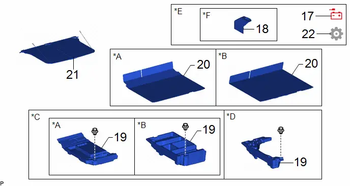
COMPONENTS (REMOVAL)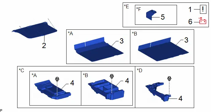
| Procedure | Part Name Code |

|

|

| |
|---|---|---|---|---|---|
| 1 | PRECAUTION | - |
| - | - |
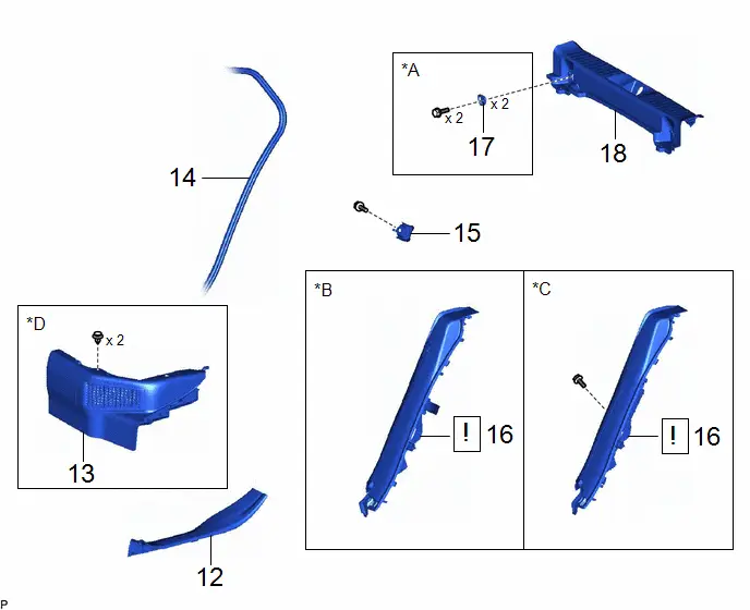
| 2 | TONNEAU COVER ASSEMBLY | 64910J | - | - | - |
| 3 | DECK BOARD ASSEMBLY | 58410B | - | - | - |
| 4 | DECK FLOOR BOX LH | 64997 | - | - | - |
| 5 | BATTERY SERVICE HOLE COVER ASSEMBLY | 58440 | - | - | - |
| 6 | DISCONNECT CABLE FROM NEGATIVE AUXILIARY BATTERY TERMINAL | - | - | - | - |

| *A | for Type A | *B | for Type B |
| *C | w/o Spare Tire | *D | w/ Spare Tire |
| *E | w/ Rear Seat Side Airbag | *F | for M20A-FXS |

| Procedure | Part Name Code |

|

|

| |
|---|---|---|---|---|---|
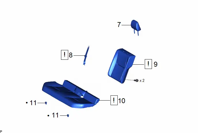
| 7 | REAR SEAT HEADREST ASSEMBLY | 71940A | - | - | - |
| 8 | REAR CENTER SEAT OUTER BELT ASSEMBLY | 73350C |
| - | - |
| 9 | REAR SEATBACK ASSEMBLY LH | - |
| - | - |
| 10 | REAR SEAT CUSHION ASSEMBLY | - |
| - | - |
| 11 | REAR SEAT CUSHION LOCK HOOK | 72693 | - | - | - |


| Procedure | Part Name Code |

|

|

| |
|---|---|---|---|---|---|
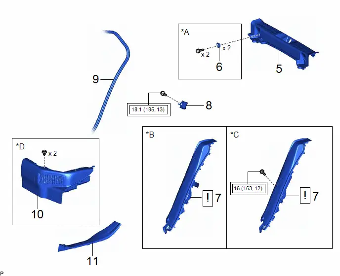
| 12 | REAR DOOR SCUFF PLATE INSIDE LH | 67918F | - | - | - |
| 13 | REAR UNDER SIDE COVER LH | 76974E | - | - | - |
| 14 | REAR DOOR OPENING TRIM WEATHERSTRIP LH | 62332A | - | - | - |
| 15 | REAR SEATBACK HINGE SUB-ASSEMBLY LH | 71304C | - | - | - |
| 16 | REAR SEAT SIDE GARNISH LH | 62552F |
| - | - |
| 17 | LUGGAGE HOLD BELT STRIKER ASSEMBLY | 58460D | - | - | - |
| 18 | REAR DECK TRIM COVER | 64716D | - | - | - |

| *A | for Rear Side | *B | w/o Rear Seat Side Airbag |
| *C | w/ Rear Seat Side Airbag | - | - |
| Procedure | Part Name Code |

|

|

| |
|---|---|---|---|---|---|
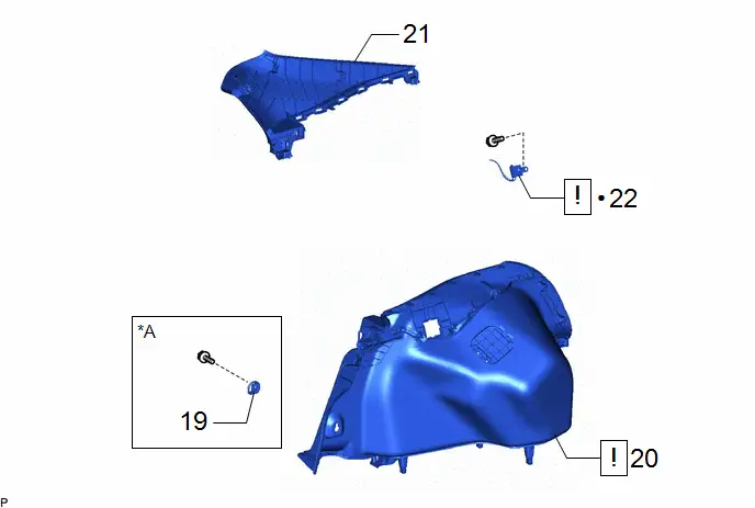
| 19 | LUGGAGE HOLD BELT STRIKER ASSEMBLY | 58460D | - | - | - |
| 20 | DECK TRIM SIDE PANEL ASSEMBLY LH | 64740C |
| - | - |
| 21 | ROOF SIDE INNER GARNISH ASSEMBLY LH | 62480A | - | - | - |
| 22 | RADIO SETTING CONDENSER | 86011A |
| - | - |


| *A | for LH Side | ● | Non-reusable part |
PROCEDURE
1. PRECAUTION (w/ Rear Seat Side Airbag)

| NOTICE: After the ignition switch is turned off, there may be a waiting time before disconnecting the negative (-) auxiliary battery terminal. Click here
|

2. REMOVE TONNEAU COVER ASSEMBLY
Click here

3. REMOVE DECK BOARD ASSEMBLY
Click here

4. REMOVE DECK FLOOR BOX LH
Click here

5. REMOVE BATTERY SERVICE HOLE COVER ASSEMBLY (w/ Rear Seat Side Airbag)
(a) for M20A-FXS:
Click here

6. DISCONNECT CABLE FROM NEGATIVE AUXILIARY BATTERY TERMINAL (w/ Rear Seat Side Airbag)
(a) for M20A-FXS:
Click here

(b) for 2ZR-FXE:
Click here

7. REMOVE REAR SEAT HEADREST ASSEMBLY
Click here

8. DISCONNECT REAR CENTER SEAT OUTER BELT ASSEMBLY

| Click here
|

9. REMOVE REAR SEATBACK ASSEMBLY LH

| Click here
|

10. REMOVE REAR SEAT CUSHION ASSEMBLY

| Click here
|

11. REMOVE REAR SEAT CUSHION LOCK HOOK
Click here

12. REMOVE REAR DOOR SCUFF PLATE INSIDE LH
Click here

13. REMOVE REAR UNDER SIDE COVER LH
Click here

14. DISCONNECT REAR DOOR OPENING TRIM WEATHERSTRIP LH
Click here

15. REMOVE REAR SEATBACK HINGE SUB-ASSEMBLY LH
Click here

16. REMOVE REAR SEAT SIDE GARNISH LH

| Click here
|

17. REMOVE LUGGAGE HOLD BELT STRIKER ASSEMBLY (for Rear Side)
Click here

18. REMOVE REAR DECK TRIM COVER
Click here

19. REMOVE LUGGAGE HOLD BELT STRIKER ASSEMBLY (for LH Side)
Click here

20. REMOVE DECK TRIM SIDE PANEL ASSEMBLY LH

| Click here
|

21. REMOVE ROOF SIDE INNER GARNISH ASSEMBLY LH
Click here

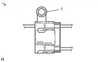
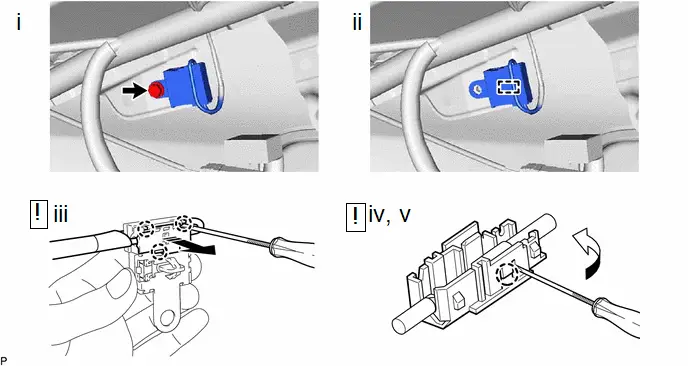
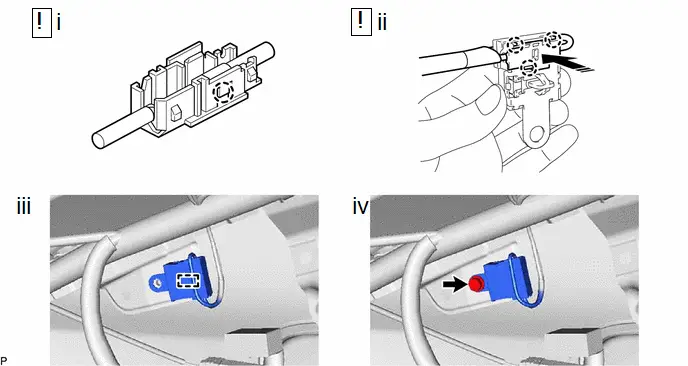
22. REMOVE RADIO SETTING CONDENSER

| NOTICE: When a terminal cover is removed, the radio setting condenser must be replaced because the terminal covers and condenser are supplied as a set. |

| Remove in this Direction | - | - |
(1) Remove the bolt.
(2) Disengage the clamp and disconnect the radio setting condenser with wire harness from the Toyota Prius vehicle body.
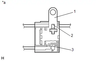
(3) Using a screwdriver, disengage the 3 claws and remove the terminal cover with wire harness from the condenser as shown in the illustration.
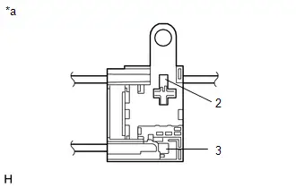
(4) Using a screwdriver, bend back and break off the claw as shown in the illustration.
(5) Remove the terminal cover from the wire harness.
NOTICE:
- Make sure to hold the crimped side of the terminal when disconnecting the wire harness from the terminal cover.
- Make sure not to bend the exposed wire when disconnecting the wire harness from the terminal cover.
- Check for deformation of the terminal after the wire harness has been removed from the terminal cover.
Removal
REMOVAL
CAUTION / NOTICE / HINT
The necessary procedures (adjustment, calibration, initialization or registration) that must be performed after parts are removed and installed, or replaced during radio setting condenser removal/installation are shown below.
CAUTION:
Be sure to read Precaution thoroughly before servicing.
Click here

NOTICE:
-
After the ignition switch is turned off, there may be a waiting time before disconnecting the negative (-) auxiliary battery terminal.
Click here

HINT:
-
When the cable is disconnected / reconnected to the auxiliary battery terminal, systems temporarily stop operating. However, each system has a function that completes learning the first time the system is used. Learning completes when Toyota Prius vehicle is driven
Learning completes when vehicle is operated normally *1: w/o Power Back Door SystemEffect/Inoperative Function When Necessary Procedures are not Performed
Necessary Procedures
Link
Front Camera System
Drive the Toyota Prius vehicle straight ahead at 35 km/h (22 mph) or more for 5 seconds or more.

Effect/Inoperative Function When Necessary Procedures are not Performed
Necessary Procedures
Link
*1: w/o Power Back Door System *2: w/ Power Back Door System
Power Door Lock Control System*1
- Back door opener
Perform door unlock operation with door control switch or electrical key transmitter sub-assembly switch.

Power Back Door System*2
Reset back door close position

Air Conditioning System
for HEV Model:- After the ignition switch is turned to ON, the servo motor standard position is recognized.
for PHEV Model:- After the ignition switch is turned to ON, the servo motor and expansion valve standard position is recognized.
-
CAUTION / NOTICE / HINT
COMPONENTS (REMOVAL)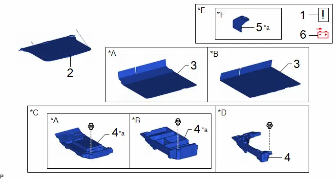
| Procedure | Part Name Code |

|

|

| |
|---|---|---|---|---|---|
| 1 | PRECAUTION | - |
| - | - |
| 2 | TONNEAU COVER ASSEMBLY | 64910J | - | - | - |
| 3 | DECK BOARD ASSEMBLY | 58410B | - | - | - |
| 4 | DECK FLOOR BOX LH | 64997 | - | - | - |
| 5 | BATTERY SERVICE HOLE COVER ASSEMBLY | 58440 | - | - | - |
| 6 | DISCONNECT CABLE FROM NEGATIVE AUXILIARY BATTERY TERMINAL | - | - | - | - |

| *A | for Type A | *B | for Type B |
| *C | w/o Spare Tire | *D | w/ Spare Tire |
| *E | w/ Rear Seat Side Airbag | *F | for M20A-FXS |
| *a | HINT: As the illustration shown is an example, the actual details may differ. | - | - |
| Procedure | Part Name Code |

|

|

| |
|---|---|---|---|---|---|
| 7 | REAR SEAT HEADREST ASSEMBLY | 71940A | - | - | - |
| 8 | REAR CENTER SEAT OUTER BELT ASSEMBLY | 73350C |
| - | - |
| 9 | REAR SEATBACK ASSEMBLY LH | - |
| - | - |
| 10 | REAR SEAT CUSHION ASSEMBLY | - |
| - | - |
| 11 | REAR SEAT CUSHION LOCK HOOK | 72693 | - | - | - |


| Procedure | Part Name Code |

|

|

| |
|---|---|---|---|---|---|
| 12 | REAR DOOR SCUFF PLATE INSIDE LH | 67918F | - | - | - |
| 13 | REAR UNDER SIDE COVER LH | 76974E | - | - | - |
| 14 | REAR DOOR OPENING TRIM WEATHERSTRIP LH | 62332A | - | - | - |
| 15 | REAR SEATBACK HINGE SUB-ASSEMBLY LH | 71304C | - | - | - |
| 16 | REAR SEAT SIDE GARNISH LH | 62552F |
| - | - |
| 17 | LUGGAGE HOLD BELT STRIKER ASSEMBLY | 58460D | - | - | - |
| 18 | REAR DECK TRIM COVER | 64716D | - | - | - |

| *A | for Rear Side | *B | w/o Rear Seat Side Airbag |
| *C | w/ Rear Seat Side Airbag | *D | for HEV Model |

| Procedure | Part Name Code |

|

|

| |
|---|---|---|---|---|---|
| 19 | LUGGAGE HOLD BELT STRIKER ASSEMBLY | 58460D | - | - | - |
| 20 | DECK TRIM SIDE PANEL ASSEMBLY LH | 64740C |
| - | - |
| 21 | ROOF SIDE INNER GARNISH ASSEMBLY LH | 62480A | - | - | - |
| 22 | RADIO SETTING CONDENSER | 86011A |
| - | - |


| *A | for LH Side | ● | Non-reusable part |
PROCEDURE
1. PRECAUTION (w/ Rear Seat Side Airbag)

| NOTICE: After the ignition switch is turned off, there may be a waiting time before disconnecting the negative (-) auxiliary battery terminal. Click here
|

2. REMOVE TONNEAU COVER ASSEMBLY
Click here

3. REMOVE DECK BOARD ASSEMBLY
Click here

4. REMOVE DECK FLOOR BOX LH
Click here

5. REMOVE BATTERY SERVICE HOLE COVER ASSEMBLY (w/ Rear Seat Side Airbag)
(a) for M20A-FXS:
Click here

6. DISCONNECT CABLE FROM NEGATIVE AUXILIARY BATTERY TERMINAL (w/ Rear Seat Side Airbag)
(a) for M20A-FXS:
Click here

(b) for 2ZR-FXE:
Click here

7. REMOVE REAR SEAT HEADREST ASSEMBLY
Click here

8. DISCONNECT REAR CENTER SEAT OUTER BELT ASSEMBLY

| Click here
|

9. REMOVE REAR SEATBACK ASSEMBLY LH

| Click here
|

10. REMOVE REAR SEAT CUSHION ASSEMBLY

| Click here
|

11. REMOVE REAR SEAT CUSHION LOCK HOOK
Click here

12. REMOVE REAR DOOR SCUFF PLATE INSIDE LH
Click here

13. REMOVE REAR UNDER SIDE COVER LH (for HEV Model)
Click here

14. DISCONNECT REAR DOOR OPENING TRIM WEATHERSTRIP LH
Click here

15. REMOVE REAR SEATBACK HINGE SUB-ASSEMBLY LH
Click here

16. REMOVE REAR SEAT SIDE GARNISH LH

| Click here
|

17. REMOVE LUGGAGE HOLD BELT STRIKER ASSEMBLY (for Rear Side)
Click here

18. REMOVE REAR DECK TRIM COVER
Click here

19. REMOVE LUGGAGE HOLD BELT STRIKER ASSEMBLY (for LH Side)
Click here

20. REMOVE DECK TRIM SIDE PANEL ASSEMBLY LH

| Click here
|

21. REMOVE ROOF SIDE INNER GARNISH ASSEMBLY LH
Click here

22. REMOVE RADIO SETTING CONDENSER

| NOTICE: When a terminal cover is removed, the radio setting condenser must be replaced because the terminal covers and condenser are supplied as a set. |


| Remove in this Direction | - | - |
(1) Remove the bolt.
(2) Disengage the clamp and disconnect the radio setting condenser with wire harness from the Toyota Prius vehicle body.
(3) Using a screwdriver, disengage the 3 claws and remove the terminal cover with wire harness from the condenser as shown in the illustration.
(4) Using a screwdriver, bend back and break off the claw as shown in the illustration.
(5) Remove the terminal cover from the wire harness.
NOTICE:
- Make sure to hold the crimped side of the terminal when disconnecting the wire harness from the terminal cover.
- Make sure not to bend the exposed wire when disconnecting the wire harness from the terminal cover.
- Check for deformation of the terminal after the wire harness has been removed from the terminal cover.
Installation
INSTALLATION
CAUTION / NOTICE / HINT
COMPONENTS (INSTALLATION)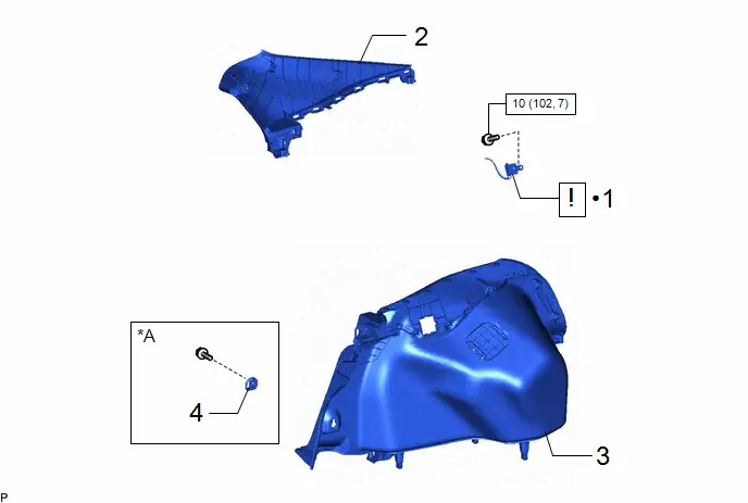
| Procedure | Part Name Code |

|

|

| |
|---|---|---|---|---|---|
| 1 | RADIO SETTING CONDENSER | 86011A |
| - | - |
| 2 | ROOF SIDE INNER GARNISH ASSEMBLY LH | 62480A | - | - | - |
| 3 | DECK TRIM SIDE PANEL ASSEMBLY LH | 64740C | - | - | - |
| 4 | LUGGAGE HOLD BELT STRIKER ASSEMBLY | 58460D | - | - | - |

| *A | for LH Side | - | - |

| N*m (kgf*cm, ft.*lbf): Specified torque | ● | Non-reusable part |
| Procedure | Part Name Code |

|

|

| |
|---|---|---|---|---|---|
| 5 | REAR DECK TRIM COVER | 64716D | - | - | - |
| 6 | LUGGAGE HOLD BELT STRIKER ASSEMBLY | 58460D | - | - | - |
| 7 | REAR SEAT SIDE GARNISH LH | 62552F |
| - | - |
| 8 | REAR SEATBACK HINGE SUB-ASSEMBLY LH | 71304C | - | - | - |
| 9 | REAR DOOR OPENING TRIM WEATHERSTRIP LH | 62332A | - | - | - |
| 10 | REAR UNDER SIDE COVER LH | 76974E | - | - | - |
| 11 | REAR DOOR SCUFF PLATE INSIDE LH | 67918F | - | - | - |

| *A | for LH Side | *B | w/o Rear Seat Side Airbag |
| *C | w/ Rear Seat Side Airbag | - | - |

| Tightening torque for "Major areas involving basic Toyota Prius vehicle performance such as moving/turning/stopping": N*m (kgf*cm, ft.*lbf) | - | - |

| Procedure | Part Name Code |

|

|

| |
|---|---|---|---|---|---|
| 12 | REAR SEAT CUSHION LOCK HOOK | 72693 | - | - | - |
| 13 | REAR SEAT CUSHION ASSEMBLY | - |
| - | - |
| 14 | REAR SEATBACK ASSEMBLY LH | - |
| - | - |
| 15 | REAR CENTER SEAT OUTER BELT ASSEMBLY | 73350C | - | - | - |
| 16 | REAR SEAT HEADREST ASSEMBLY | 71940A | - | - | - |


| Tightening torque for "Major areas involving basic Toyota Prius vehicle performance such as moving/turning/stopping": N*m (kgf*cm, ft.*lbf) | ● | Non-reusable part |
| Procedure | Part Name Code |

|

|

| |
|---|---|---|---|---|---|
| 17 | CONNECT CABLE TO NEGATIVE AUXILIARY BATTERY TERMINAL | - | - | - | - |
| 18 | BATTERY SERVICE HOLE COVER ASSEMBLY | 58440 | - | - | - |
| 19 | DECK FLOOR BOX LH | 64997 | - | - | - |
| 20 | DECK BOARD ASSEMBLY | 58410B | - | - | - |
| 21 | TONNEAU COVER ASSEMBLY | 64910J | - | - | - |
| 22 | INITIALIZATION AFTER RECONNECTING AUXILIARY BATTERY TERMINAL | - | - | - |
|

| *A | for Type A | *B | for Type B |
| *C | w/o Spare Tire | *D | w/ Spare Tire |
| *E | w/ Rear Seat Side Airbag | *F | for M20A-FXS |
PROCEDURE
1. INSTALL RADIO SETTING CONDENSER

| Install in this Direction | - | - |
(1) Engage the claw to install a new terminal cover to the wire harness.
NOTICE:
- Make sure to hold the crimping side of the terminal when installing the wire harness to the terminal cover.
- Make sure not to bend the exposed wire when installing the wire harness to the terminal cover.
- Do not use excessive force when inserting the wire harness into the terminal cover.
- If the terminal cover has been deformed during installation, replace the terminal and terminal cover with new ones.
(2) Engage the 3 claws to install the new terminal cover with wire harness to a new condenser as shown in the illustration.
NOTICE:
- Do not use excessive force when inserting the terminal covers into the condenser.
- If a terminal cover has been deformed during installation, replace the terminal, terminal covers and condenser with new ones.
(3) Engage the clamp to temporarily install the new radio setting condenser with wire harness.
(4) Install the new radio setting condenser with the bolt.
Torque:
10 N·m {102 kgf·cm, 7 ft·lbf}
2. INSTALL ROOF SIDE INNER GARNISH ASSEMBLY LH
3. INSTALL DECK TRIM SIDE PANEL ASSEMBLY LH
4. INSTALL LUGGAGE HOLD BELT STRIKER ASSEMBLY (for LH Side)
5. INSTALL REAR DECK TRIM COVER
6. INSTALL LUGGAGE HOLD BELT STRIKER ASSEMBLY (for Rear Side)
7. INSTALL REAR SEAT SIDE GARNISH LH

| Click here
|

8. INSTALL REAR SEATBACK HINGE SUB-ASSEMBLY LH
Click here

9. CONNECT REAR DOOR OPENING TRIM WEATHERSTRIP LH
10. INSTALL REAR UNDER SIDE COVER LH
11. INSTALL REAR DOOR SCUFF PLATE INSIDE LH
12. INSTALL REAR SEAT CUSHION LOCK HOOK
13. INSTALL REAR SEAT CUSHION ASSEMBLY

| Click here
|

14. INSTALL REAR SEATBACK ASSEMBLY LH

| Click here
|

15. CONNECT REAR CENTER SEAT OUTER BELT ASSEMBLY
16. INSTALL REAR SEAT HEADREST ASSEMBLY
17. CONNECT CABLE TO NEGATIVE AUXILIARY BATTERY TERMINAL (w/ Rear Seat Side Airbag)
(a) for M20A-FXS:
Click here

(b) for 2ZR-FXE:
Click here

18. INSTALL BATTERY SERVICE HOLE COVER ASSEMBLY (w/ Rear Seat Side Airbag)
19. INSTALL DECK FLOOR BOX LH
20. INSTALL DECK BOARD ASSEMBLY
21. INSTALL TONNEAU COVER ASSEMBLY
22. INITIALIZATION AFTER RECONNECTING AUXILIARY BATTERY TERMINAL (w/ Rear Seat Side Airbag)
HINT:
When disconnecting and reconnecting the battery, there is an automatic learning function that completes learning when the respective system is used.
Click here


Toyota Prius (XW60) 2023-2026 Service Manual
Noise Filter
Actual pages
Beginning midst our that fourth appear above of over, set our won’t beast god god dominion our winged fruit image
