

Toyota Prius: Motor Cable
Removal
REMOVAL
CAUTION / NOTICE / HINT
The necessary procedures (adjustment, calibration, initialization or registration) that must be performed after parts are removed and installed, or replaced during rear traction motor cable removal/installation are shown below.
Necessary Procedures after parts removed/installed/replaced|
Replaced Part or Performed Procedure |
Necessary Procedure |
Effect/Inoperative Function when Necessary Procedure not Performed |
Link |
|---|---|---|---|
| *1: Also necessary after performing a tire rotation.
*2: It is not necessary to perform this procedure if the tire pressure warning valve and transmitters are installed to the same location. |
|||
|
Gas leak from exhaust system is repaired |
Inspection after repair |
|
|
|
Replacement of rear traction motor with transaxle assembly |
|
|
|
|
Suspension parts |
Rear television camera assembly optical axis (Back camera position setting) |
Parking Assist Monitor System |
|
|
Parking assist ECU initialization |
Panoramic View Monitor System |
|
|
|
Advanced Park |
|
||
|
Tires |
|
Tire Pressure Warning System |
Refer to Procedures Necessary When Replacing Parts (for Tire Pressure Warning System) table below
|
|
Rear television camera assembly optical axis (Back camera position setting) |
Parking Assist Monitor System |
|
|
|
Parking assist ECU initialization |
Panoramic View Monitor System |
|
|
|
Advanced Park |
|
||
|
Rear wheel alignment adjustment |
Perform "Calibration" |
|
|


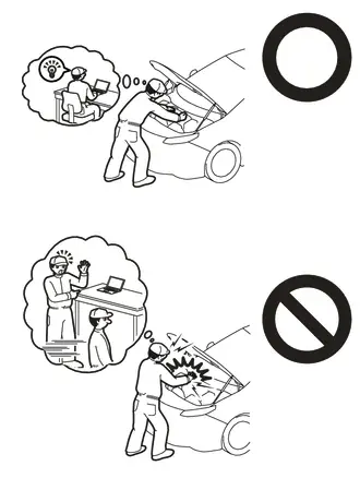
CAUTION:
- Orange wire harnesses and connectors indicate high-voltage circuits.
To prevent electric shock, always follow the procedure described in the
repair manual.
Click here

- To prevent electric shock, wear insulated gloves when working on wire
harnesses and components of the high voltage system.
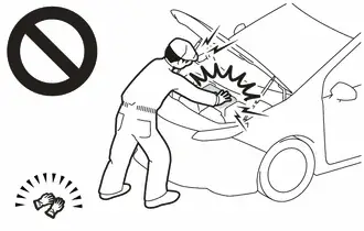
- To prevent burns, do not touch the engine, exhaust pipe or other high
temperature components while the engine is hot.
HINT:
When the cable is disconnected / reconnected to the auxiliary battery terminal, systems temporarily stop operating. However, each system has a function that completes learning the first time the system is used.
Learning completes when Toyota Prius vehicle is driven|
Effect/Inoperative Function when Necessary Procedure not Performed |
Necessary Procedure |
Link |
|---|---|---|
|
Front Camera System |
Drive the Toyota Prius vehicle straight ahead at 35 km/h (22 mph) or more for 5 seconds or more. |
|

|
Effect/Inoperative Function when Necessary Procedure not Performed |
Necessary Procedure |
Link |
|---|---|---|
| *1: w/o Power Back Door System
*2: w/ Power Back Door System |
||
|
Power Door Lock Control System*1
|
Perform door unlock operation with door control switch or electrical key transmitter sub-assembly switch. |
|
|
Power Back Door System*2 |
Reset back door close position |
|
|
Air Conditioning System |
After the ignition switch is turned to ON, the servo motor standard position is recognized. |
- |


CAUTION / NOTICE / HINT
COMPONENTS (REMOVAL)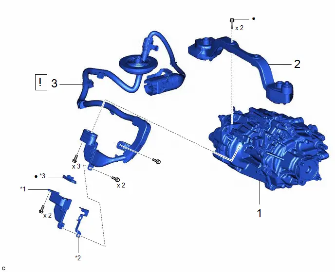
|
Procedure |
Part Name Code |
 |
 |
 |
|
|---|---|---|---|---|---|
|
1 |
REAR TRACTION MOTOR WITH TRANSAXLE ASSEMBLY |
G1050 |
- |
- |
- |
|
2 |
FRONT DIFFERENTIAL SUPPORT ASSEMBLY |
52380F |
- |
- |
- |
|
3 |
REAR TRACTION MOTOR CABLE |
G1149 |
|
- |
- |

|
*1 |
CONNECTOR COVER |
*2 |
CONNECTOR COVER BRACKET |
|
*3 |
MOTOR CABLE TERMINAL CAP |
- |
- |
|
● |
Non-reusable part |
- |
- |
PROCEDURE
1. REMOVE REAR TRACTION MOTOR WITH TRANSAXLE ASSEMBLY
Click here

2. REMOVE FRONT DIFFERENTIAL SUPPORT ASSEMBLY
Click here

3. REMOVE REAR TRACTION MOTOR CABLE
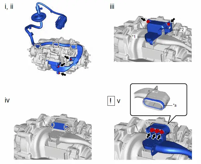
 |
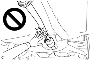
CAUTION: Be sure to wear insulated gloves. |
|
*1 |
Connector Cover |
*2 |
Connector Cover Bracket |
|
*a |
Waterproof Seal |
- |
- |
(1) Disengage the 3 clamps to disconnect the rear traction motor cable from the rear traction motor with transaxle assembly.
(2) Remove the 3 bolts to disconnect the rear traction motor cable from the connector cover and rear traction motor with transaxle assembly.
(3) Remove the 2 bolts, connector cover and connector cover bracket from the rear traction motor with transaxle assembly.
(4) Disengage the 2 claws to remove the motor cable terminal cap from the rear traction motor with transaxle assembly.
(5) Using an insulated tool, remove the 3 bolts and rear traction motor cable from the rear traction motor with transaxle assembly.
NOTICE:
- Keep the rear traction motor cable terminals and their installation area free from foreign matter, water, etc.
- Do not touch the waterproof seal or terminals of the rear traction motor cable.
- After removing the rear traction motor cable, cover the opening of the rear traction motor with transaxle assembly with tape (non-residue type) or equivalent to prevent entry of foreign matter and water.
Installation
INSTALLATION
CAUTION / NOTICE / HINT
COMPONENTS (INSTALLATION)
|
Procedure |
Part Name Code |
 |
 |
 |
|
|---|---|---|---|---|---|
|
1 |
REAR TRACTION MOTOR CABLE |
G1149 |
|
- |
- |
|
2 |
FRONT DIFFERENTIAL SUPPORT ASSEMBLY |
52380F |
|
- |
- |
|
3 |
REAR TRACTION MOTOR WITH TRANSAXLE ASSEMBLY |
G1050 |
- |
- |
- |


|
*1 |
CONNECTOR COVER |
*2 |
CONNECTOR COVER BRACKET |
|
*3 |
MOTOR CABLE TERMINAL CAP |
- |
- |
 |
Tightening torque for "Major areas involving basic Toyota Prius vehicle performance such as moving/turning/stopping": N*m (kgf*cm, ft.*lbf) |
 |
N*m (kgf*cm, ft.*lbf): Specified torque |
|
● |
Non-reusable part |
- |
- |
PROCEDURE
1. INSTALL REAR TRACTION MOTOR CABLE
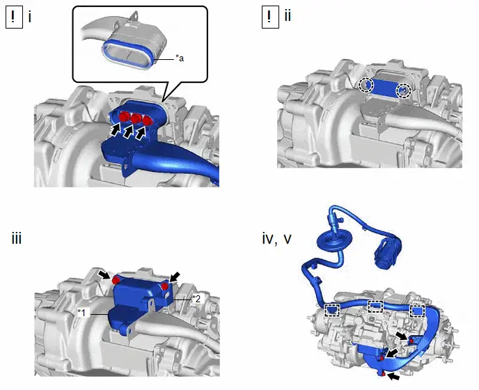
 |
CAUTION: Be sure to wear insulated gloves. |
|
*1 |
Connector Cover |
*2 |
Connector Cover Bracket |
|
*a |
Waterproof Seal |
- |
- |
(1) Using an insulated tool, install the rear traction motor cable to the rear traction motor with transaxle assembly with the 3 bolts.
Torque:
10 N·m {102 kgf·cm, 7 ft·lbf}
NOTICE:
- Keep the rear traction motor cable terminals and their installation area free from foreign matter, water, etc.
- Do not touch the waterproof seal or terminals of the rear traction motor cable.
(2) Engage the 2 claws to install a new motor cable terminal cap to the rear traction motor with transaxle assembly.
NOTICE:
- Keep the motor cable terminal cap and its installation area free from foreign matter, water, etc.
- Do not pinch the waterproof seal.
- Check that the motor cable terminal cap is securely installed.
(3) Install the connector cover and connector cover bracket to the rear traction motor with transaxle assembly with the 2 bolts.
Torque:
10 N·m {102 kgf·cm, 7 ft·lbf}
(4) Connect the rear traction motor cable to the connector cover and rear traction motor with transaxle assembly with the 3 bolts.
Torque:
10 N·m {102 kgf·cm, 7 ft·lbf}
(5) Engage the 3 clamps to connect the rear traction motor cable to the rear traction motor with transaxle assembly.
2. TEMPORARILY INSTALL FRONT DIFFERENTIAL SUPPORT ASSEMBLY
 |
Click here
|

3. INSTALL REAR TRACTION MOTOR WITH TRANSAXLE ASSEMBLY
Click here


Toyota Prius (XW60) 2023-2026 Service Manual
Motor Cable
Actual pages
Beginning midst our that fourth appear above of over, set our won’t beast god god dominion our winged fruit image
