

Toyota Prius: Millimeter Wave Radar Sensor
- Removal
- Installation
- Before Starting Driving Adjustment
- Driving Adjustment
- Target Adjustment(flat Surface Target)
Removal
REMOVAL
CAUTION / NOTICE / HINT
The necessary procedures (adjustment, calibration, initialization or registration) that must be performed after parts are removed and installed, or replaced during millimeter wave radar sensor assembly removal/installation are shown below.
Necessary Procedures After Parts Removed/Installed/Replaced|
Replaced Part or Performed Procedure |
Necessary Procedures |
Effect/Inoperative Function When Necessary Procedures are not Performed |
Link |
|---|---|---|---|
|
Millimeter wave radar sensor assembly |
Adjust millimeter wave radar sensor assembly |
|
Triangle Target: Flat Surface Target: Driving Adjustment: |


CAUTION / NOTICE / HINT
COMPONENTS (REMOVAL)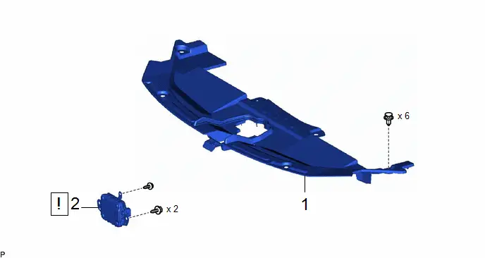
|
Procedure |
Part Name Code |
 |
 |
 |
|
|---|---|---|---|---|---|
|
1 |
RADIATOR SUPPORT OPENING COVER |
53289A |
- |
- |
- |
|
2 |
MILLIMETER WAVE RADAR SENSOR ASSEMBLY |
88211B |
|
- |
- |

PROCEDURE
1. REMOVE RADIATOR SUPPORT OPENING COVER
Click here 
2. REMOVE MILLIMETER WAVE RADAR SENSOR ASSEMBLY
 |
NOTICE: Do not reuse the millimeter wave radar sensor assembly if it has been dropped or subjected to a severe impact. |
|
*a |
Bolt |
*b |
Screw |
Installation
INSTALLATION
CAUTION / NOTICE / HINT
COMPONENTS (INSTALLATION)
|
Procedure |
Part Name Code |
 |
 |
 |
|
|---|---|---|---|---|---|
|
1 |
MILLIMETER WAVE RADAR SENSOR ASSEMBLY |
88211B |
|
- |
- |
|
2 |
RADIATOR SUPPORT OPENING COVER |
53289A |
- |
- |
- |
|
3 |
ADJUST MILLIMETER WAVE RADAR SENSOR ASSEMBLY |
88211B |
- |
- |
|


 |
N*m (kgf*cm, ft.*lbf): Specified torque |
- |
- |
PROCEDURE
1. INSTALL MILLIMETER WAVE RADAR SENSOR ASSEMBLY
 |
NOTICE: If the millimeter wave radar sensor assembly has been struck or dropped, replace the millimeter wave radar sensor assembly with a new one. |
|
*a |
Bolt |
*b |
Screw |
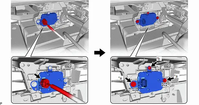
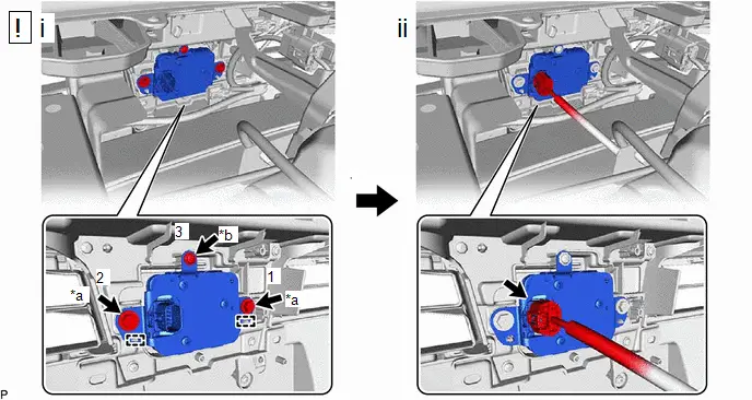
(1) Engage the 2 guides and install the millimeter wave radar sensor assembly with the 2 bolts and screw in the order shown in the illustration.
Torque:
Bolt: :
2.5 N·m {25 kgf·cm, 22 in·lbf}
NOTICE:
Do not overtighten the screw. The radiator grille may be damaged.
(2) Connect the connector.
2. INSTALL RADIATOR SUPPORT OPENING COVER
3. ADJUST MILLIMETER WAVE RADAR SENSOR ASSEMBLY
(a) When the millimeter wave radar sensor assembly is replaced with a new one, adjustment of the radar sensor beam axis must be performed.
HINT:
Millimeter wave radar sensor assembly learning can be performed by using either Triangle Target, Flat Surface Target or Driving Adjustment.
- Target Adjustment (Triangle Target):
Click here

- Target Adjustment (Flat Surface Target):
Click here

- Driving Adjustment:
Click here

Before Starting Driving Adjustment
BEFORE STARTING DRIVING ADJUSTMENT
CAUTION / NOTICE / HINT
HINT:
- Purpose of millimeter wave radar beam axis learning
- If the installation position or orientation of the millimeter wave radar sensor is changed due to it being removed and reinstalled or replaced with a new one, or due to the front bumper or radiator grille being replaced, it is necessary for the millimeter wave radar sensor to learn the driving direction of the Toyota Prius vehicle in order for each driving support system to operate correctly.
- Vehicle driving direction
*a
Toyota Prius Vehicle driving direction
- Adjustment
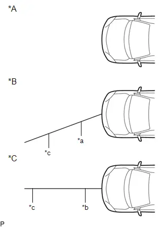
*A
When using a new millimeter wave radar sensor
*B
When reusing millimeter wave radar sensor
*C
Millimeter wave radar sensor after adjustment
*a
Previously learned driving direction
*b
Newly learned driving direction
*c
Horizontal direction
- Adjustment
PROCEDURE
1. PERFORM DRIVING ADJUSTMENT
NOTICE:
- When performing the driving adjustment, obey all applicable traffic laws.
- Select a road where the driving adjustment can be carried out safely.
|
(a) Driving adjustment concept
|
|
(b) Driving conditions
- Drive the Toyota Prius vehicle straight ahead at a speed of 30 km/h (19 mph) or more.
- Perform the adjustment outside during daytime, on a sunny or cloudy day.
- If preceding vehicles are present, they should be kept at a distance of at least 20 m (66 ft.)
- There is a stationary object on the roadside such as a guardrail.
- Ensure that there is no snow, ice, or foreign matter on the front or rear of the radar sensor cover or on the front surface of the sensor.
- Make sure that no covers other than the genuine radar sensor cover are installed.
- Drive on a road that does not have heavy snow accumulation around it.
NOTICE:
If the sensor axis is excessively misaligned, the online axis alignment may not be able to make progress.
The total cumulative time that is required for the adjustment to complete when the Toyota Prius vehicle is driven with all conditions met is approximately 5 to 15 minutes.
HINT:
- If the adjustment does not complete within a total cumulative time of 15 minutes when the vehicle is driven with all conditions met, perform the adjustment on another route.
- If the adjustment does not complete within a total cumulative time of 30 minutes when the Toyota Prius vehicle is driven with all conditions met, perform the adjustment using target recognition.
- If the vehicle is driven unsteadily or many lane changes are performed, the time taken for adjustment to complete may increase.
(c) Road environment
HINT:
When driving on a bumpy or unpaved road, making frequent accelerations and decelerations, etc., the millimeter wave radar sensor assembly condition may be unstable, which may cause adjustment to take a long time.
- Road environments conducive to adjustment
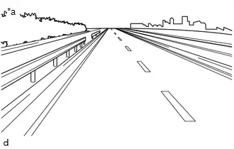
*a
Roads with stationary metallic objects such as guard rails
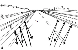
- Road environments which hinder adjustment
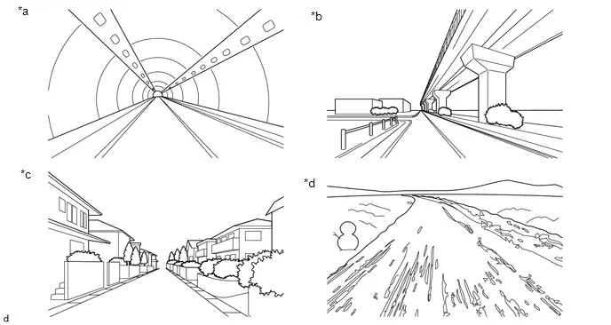
*a
Inside tunnels where there are many diffuse radar reflections
*b
Underneath elevated structures where there are many diffuse radar reflections
*c
In residential neighborhoods where there are many diffuse radar reflections
*d
Snowy roads, dirt roads, etc., where there are very few radar reflections
Driving Adjustment
DRIVING ADJUSTMENT
CAUTION / NOTICE / HINT
CAUTION:
Radiofrequency radiation exposure information:
- This equipment complies with FCC radiation exposure limits set forth for an uncontrolled environment.
- This equipment should be kept with minimum distance of 20 cm (7.87 in.) between the radiator (antenna) and your body at all times during adjustment.
- This transmitter must not be co-located or operating in conjunction with any other antenna or transmitter.
NOTICE:
- Make sure to read "Before Starting Driving Adjustment" before proceeding
with work.
Click here

- Make sure that the alignment is suitable and non-standard tires are not installed.
- Make sure to perform the transition to online axis alignment mode with the Toyota Prius vehicle stopped.
- Transitioning to online axis alignment mode will erase the learning value, so make sure to complete the adjustment.
- Turning the ignition switch off while in online axis alignment mode will cause the system to exit online axis alignment mode, so to continue with the adjustment, it is necessary to transition to online axis alignment mode again.
- All of the driving support system functions will be inoperative while the adjustment is in progress.
- When driving the Toyota Prius vehicle with the GTS connected, be careful with how the wires are routed.
- If the adjustment does not complete within a total cumulative time of 15 minutes when the vehicle is driven with all conditions met, perform the adjustment on another route.
- If the adjustment does not complete within a total cumulative time of 30 minutes when the Toyota Prius vehicle is driven with all conditions met, perform the adjustment using target recognition.
- After adjustment is complete, to start the various systems it is necessary to turn the ignition switch off and then to ON again.
- In situations such as when the online axis alignment terminates abnormally, to perform online axis alignment again, turn the ignition switch off and then back to ON and enter online axis alignment mode again.
PROCEDURE
1. PERFORM MILLIMETER WAVE RADAR SENSOR OPTICAL AXIS LEARNING (When driving with GTS connected to Toyota Prius vehicle)
(a) Adjust the tire pressures to the standard values.
Click here 
(b) Make sure the surfaces of the radiator grille emblem and millimeter wave radar sensor assembly are clean and have no dirt, snow, or other matter adhering to them.
(c) Clean away any foreign matter adhering to the surface of the radiator grille emblem.
(d) Check that there is no damage or deformation around the front exterior area of the Toyota Prius vehicle.
(e) Check that the radiator grille and front bumper assembly are securely installed, and that there is no damage or deformation around the installation areas. If any abnormalities are found, repair or replace parts as necessary.
(f) Perform Transition to Online Axis Alignment Mode.
(1) With the ignition switch off, connect the GTS to the DLC3.
(2) Turn the ignition switch to ON.
(3) Enter the following menus: Body Electrical / Front Radar Sensor / Utility / Transition to Online Axis Alignment Mode.
for Type A:
Body Electrical > Front Radar Sensor > Utility|
Tester Display |
|---|
|
Transition to Online Axis Alignment Mode |
for Type B:
Body Electrical > Front Radar Sensor > Utility|
Tester Display |
|---|
|
Transition to Online Axis Alignment Mode |
(4) Confirm the conditions displayed on the screen and then press "Next".
(5) Select "Front radar sensor" and then press "Next".
(6) Check the GTS screen and confirm that it has transitioned to online axis alignment mode.
(7) Press "Next".
(g) Online axis adjustment (Optical Axis Learning)
(1) Drive the Toyota Prius vehicle to perform optical axis learning.
HINT:
If the alignment is performed with the GTS connected to the vehicle, the alignment progress can be monitored through 5 stages on the GTS screen.
(2) If the online axis alignment completes normally, the buzzer will sound intermittently for 2 seconds.
NOTICE:
- If the alignment terminates abnormally, the buzzer will sound for 3 seconds continuously.
- If an error code is displayed, perform troubleshooting according to
the following table, then perform the beam axis alignment again.
Error No.
Error Description
Cause of Error
Action to be Taken
6
Target angle abnormality
- The beam axis of the millimeter wave radar sensor assembly is outside the automatic correction range.
Check the condition of the millimeter wave radar sensor assembly, radiator grille and front bumper assembly.
7
Radar abnormality
- Operation of the millimeter wave radar sensor assembly is abnormal.
Replace the millimeter wave radar sensor assembly.
8
Radar dirtiness
- There is dirt on the radiator grille garnish or millimeter wave radar sensor assembly.
- Clean the radiator grille garnish or millimeter wave radar sensor assembly.
- Check that there is no foreign matter between the millimeter wave radar sensor assembly and radiator grille garnish.
9
Temperature abnormality
- The temperature around the millimeter wave radar sensor assembly is too high.
Wait until the temperature drops to the operable range (-30 to 50°C).
10
Voltage abnormality
- IG power source voltage is outside the operable range of the millimeter wave radar sensor assembly.
Check the auxiliary battery voltage (specified condition: 10 to 16 V).
- for M20A-FXS:
Click here


- for 2ZR-FXE:
Click here

11
External communication abnormality
- CAN communication between forward recognition camera and the millimeter wave radar sensor assembly is abnormal.
Check the condition of the connectors and wire harness.
12
Radar axis aiming failure upward
- The beam axis of the millimeter wave radar sensor assembly is deviated.
Check the condition of the millimeter wave radar sensor assembly, radiator grille and front bumper assembly.
13
Radar axis aiming failure downward
- The beam axis of the millimeter wave radar sensor assembly is deviated.
Check the condition of the millimeter wave radar sensor assembly, radiator grille and front bumper assembly.
14
Toyota Prius Vehicle speed abnormality
- The vehicle is moving.
Ensure that the vehicle remains stationary.
15
Other
- Operation of the yaw rate sensor is abnormal.
- Driving beam axis alignment was forcibly terminated.
Check for DTCs (Front Recognition Camera).
Check for DTCs (ABS / VSC / TRC).
16
Time out
- The Toyota Prius vehicle cannot communicate with GTS normally.
- Operation of the millimeter wave radar sensor assembly is abnormal.
- Ensure that the vehicle is connected with the GTS correctly.
- Perform online axis adjustment again and replace the millimeter wave radar sensor assembly if the same error code is output.
18
Toyota Prius Vehicle information undefined
- CAN communication between forward recognition camera and the millimeter wave radar sensor assembly is abnormal.
Check the connectors of the millimeter wave radar sensor assembly, forward recognition camera and the junction block are firmly connected.
(3) Press "Exit" to exit the Online axis adjustment mode.
(4) Turn the ignition switch off.
(5) Turn the ignition switch to ON and check that the warning light turns off.
(6) Turn the ignition switch off.
(7) Disconnect the GTS from the DLC3.
(h) Millimeter wave radar sensor assembly optical axis learning is complete.
(i) After beam axis adjustment completes, clear the following system Toyota Prius vehicle control history entries.
(1) Clear vehicle control history (Front Radar Sensor System).
Click here 

(2) Clear vehicle control history (Front Camera System).
Click here 

2. PERFORM MILLIMETER WAVE RADAR SENSOR OPTICAL AXIS LEARNING (When driving with GTS not connected to Toyota Prius vehicle)
(a) Adjust the tire pressures to the standard values.
Click here 
(b) Make sure the surfaces of the radiator grille emblem and millimeter wave radar sensor assembly are clean and have no dirt, snow, or other matter adhering to them.
(c) Clean away any foreign matter adhering to the surface of the radiator grille emblem.
(d) Check that there is no damage or deformation around the front exterior area of the Toyota Prius vehicle.
(e) Check that the radiator grille and front bumper assembly are securely installed, and that there is no damage or deformation around the installation areas. If any abnormalities are found, repair or replace parts as necessary.
(f) Perform Transition to Online Axis Alignment Mode.
(1) With the ignition switch off, connect the GTS to the DLC3.
(2) Turn the ignition switch to ON.
(3) Enter the following menus: Body Electrical / Front Radar Sensor / Utility / Transition to Online Axis Alignment Mode.
for Type A:
Body Electrical > Front Radar Sensor > Utility|
Tester Display |
|---|
|
Transition to Online Axis Alignment Mode |
for Type B:
Body Electrical > Front Radar Sensor > Utility|
Tester Display |
|---|
|
Transition to Online Axis Alignment Mode |
(4) Confirm the conditions displayed on the screen and then press "Next".
(5) Select "Front radar sensor" and then press "Next".
(6) Check the GTS screen and confirm that it has transitioned to online axis alignment mode.
(7) Press "Next".
(8) In accordance with the instructions on the screen press "Exit" and then disconnect the GTS from the DLC3.
(g) Online axis adjustment (Optical Axis Learning)
(1) Drive the Toyota Prius vehicle to perform optical axis learning.
(2) If the online axis alignment completes normally, the buzzer will sound intermittently for 2 seconds.
NOTICE:
- If the alignment terminates abnormally, the buzzer will sound for 3 seconds continuously.
- When the system terminates abnormally, connect the GTS and refer to
the following error code table, then perform beam axis alignment again.
Click here

Error No.
Error Description
Cause of Error
Action to be Taken
6
Target angle abnormality
- The beam axis of the millimeter wave radar sensor assembly is outside the automatic correction range.
Check the condition of the millimeter wave radar sensor assembly, radiator grille and front bumper assembly.
7
Radar abnormality
- Operation of the millimeter wave radar sensor assembly is abnormal.
Replace the millimeter wave radar sensor assembly.
8
Radar dirtiness
- There is dirt on the radiator grille garnish or millimeter wave radar sensor assembly.
- Clean the radiator grille garnish or millimeter wave radar sensor assembly.
- Check that there is no foreign matter between the millimeter wave radar sensor assembly and radiator grille garnish.
9
Temperature abnormality
- The temperature around the millimeter wave radar sensor assembly is too high.
Wait until the temperature drops to the operable range (-30 to 50°C).
10
Voltage abnormality
- IG power source voltage is outside the operable range of the millimeter wave radar sensor assembly.
Check the auxiliary battery voltage (specified condition: 10 to 16 V).
- for M20A-FXS:
Click here


- for 2ZR-FXE:
Click here

11
External communication abnormality
- CAN communication between forward recognition camera and the millimeter wave radar sensor assembly is abnormal.
Check the condition of the connectors and wire harness.
12
Radar axis aiming failure upward
- The beam axis of the millimeter wave radar sensor assembly is deviated.
Check the condition of the millimeter wave radar sensor assembly, radiator grille and front bumper assembly.
13
Radar axis aiming failure downward
- The beam axis of the millimeter wave radar sensor assembly is deviated.
Check the condition of the millimeter wave radar sensor assembly, radiator grille and front bumper assembly.
14
Toyota Prius Vehicle speed abnormality
- The vehicle is moving.
Ensure that the vehicle remains stationary.
15
Other
- Operation of the yaw rate sensor is abnormal.
- Driving beam axis alignment was forcibly terminated.
Check for DTCs (Front Recognition Camera).
Check for DTCs (ABS / VSC / TRC).
16
Time out
- The Toyota Prius vehicle cannot communicate with GTS normally.
- Operation of the millimeter wave radar sensor assembly is abnormal.
- Ensure that the vehicle is connected with the GTS correctly.
- Perform online axis adjustment again and replace the millimeter wave radar sensor assembly if the same error code is output.
18
Toyota Prius Vehicle information undefined
- CAN communication between forward recognition camera and the millimeter wave radar sensor assembly is abnormal.
Check the connectors of the millimeter wave radar sensor assembly, forward recognition camera and the junction block are firmly connected.
(3) Turn the ignition switch off.
(4) Turn the ignition switch to ON and check that the warning light turns off.
(5) Turn the ignition switch off.
(h) Millimeter wave radar sensor assembly optical axis learning is complete.
(i) After beam axis adjustment completes, clear the following system Toyota Prius vehicle control history entries.
(1) Clear vehicle control history (Front Radar Sensor System).
Click here 

(2) Clear vehicle control history (Front Camera System).
Click here 

Target Adjustment(flat Surface Target)
TARGET ADJUSTMENT(FLAT SURFACE TARGET)
CAUTION / NOTICE / HINT
CAUTION:
Radiofrequency radiation exposure information:
- This equipment complies with FCC radiation exposure limits set forth for an uncontrolled environment.
- This equipment should be kept with minimum distance of 20 cm (7.87 in.) between the radiator (antenna) and your body at all times during adjustment.
- This transmitter must not be co-located or operating in conjunction with any other antenna or transmitter.
PROCEDURE
1. PREPARATION FOR MILLIMETER WAVE RADAR SENSOR ASSEMBLY ADJUSTMENT
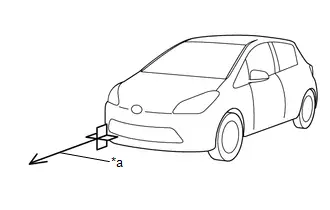
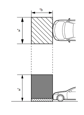
(a) Park the Toyota Prius vehicle on a level surface where the area in front of the vehicle shown in the illustration is free of metal objects.
|
*a |
2.5 m (8.2 ft.) |
|
*b |
2 m (6.56 ft.) |

|
Do not place any metal objects in this area |

|
Do not place metal objects with a height of more than 50 mm (1.97 in.) in this area |
HINT:
Metal objects with a height of 50 mm (1.97 in.) or less placed within the area shown in the illustration will not affect the adjustment.
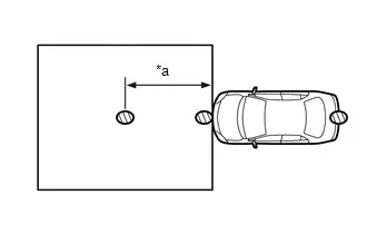
(b) Check the levelness of the ground.
(1) Check the levelness of the ground at the 3 points shown in the illustration.
|
*a |
1.5 m (4.92 ft.) |

|
Levelness Check Point |
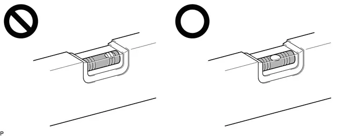
(2) Place the level on each levelness check point and check that the air bubble of the level is centered.
(c) Adjust the tire inflation pressure to the specified pressure.
Click here

(d) Clean the radiator grille garnish or millimeter wave radar sensor assembly.
(e) Visually inspect the front of the Toyota Prius vehicle.
HINT:
Confirm that there is no damage or deformation.
(f) Visually inspect the front bumper assembly, radiator grille and stays.
HINT:
Confirm that there is no damage or deformation.
(g) Check that the radiator grille and front bumper assembly are securely installed, and that there is no damage or deformation around the installation areas. If any abnormalities are found, repair or replace parts as necessary.
2. ADJUST MILLIMETER WAVE RADAR SENSOR ASSEMBLY HORIZONTALLY
HINT:
The vertical axis deviation can only be checked and cannot be adjusted.
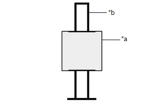
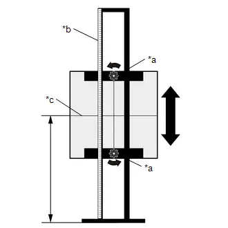
(a) Adjust SST (flat surface target) height.
|
(1) Check that SST (flat surface target) has no damage or deformation. SST: 09870-60100 SST: 09870-60110 |
|
(2) Check that SST (flat surface target) is assembled correctly.
(3) Check that SST (flat surface target) has no looseness or wobble.
|
(4) Loosen the top and bottom handles of SST (panel stand), and while checking the included scale, adjust the height of SST (flat surface target) as shown in the illustration so that its height reference line is at the same height as the millimeter wave radar sensor assembly, then re-tighten the top and bottom handles. HINT:
Reference Value: 601 mm (1.97 ft.) |
|
(b) Place SST (flat surface target).
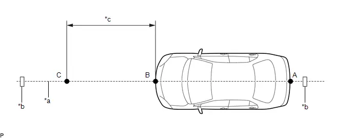
(1) Hang a weight with a pointed tip from the center of the rear emblem, and mark the rear center point of the Toyota Prius vehicle (point A) on the ground.
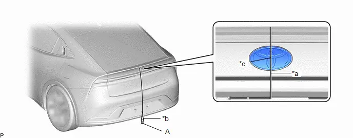
|
*a |
String |
*b |
Weight |
|
*c |
Center |
- |
- |
HINT:
Lightly flick the string with your fingers several times to confirm that the string is perpendicular to the ground.
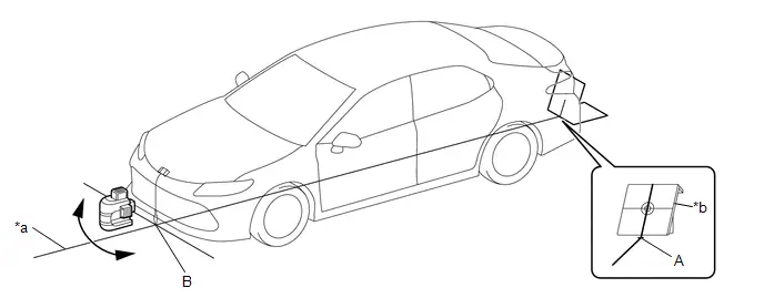
(2) Hang a weight with a pointed tip from the center of the radiator grille (or front panel) emblem, and mark the front center point of the Toyota Prius vehicle (point B) on the ground.
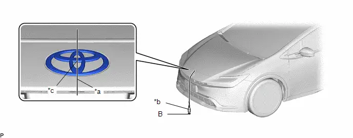
|
*a |
String |
*b |
Weight |
|
*c |
Center |
- |
- |
HINT:
Lightly flick the string with your fingers several times to confirm that the string is perpendicular to the ground.
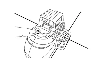
(3) When using a laser line marker:
NOTICE:
Do not look directly into the laser beam.
- Press the laser mode button on the laser line marker to activate the
laser line emitters.
- Align the laser beam ground marking point (cross portion) with point
B.
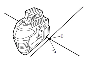
*a
Ground Marking Point (Cross Portion)
- Align the center of the target panel with point A, and set the target
panel so that it faces forward.
*a
Center Line
*b
Target Panel
- Adjust the position of the laser line marker so that the laser beam is aligned with the center line of the target panel.
- Extend a tape measure at least 1500 mm (4.92 ft.) in length from point
B, and set the tape measure in place.
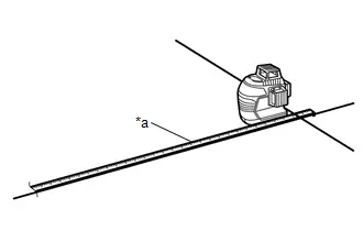
*a
Tape Measure
- Mark point C at a distance of 1500 mm (4.92 ft.) from point B, and apply
a 300 mm (11.81 in.) piece of tape alongside the tape measure so that the
tape extends 150 mm (5.91 in.) to the front and rear of point C.
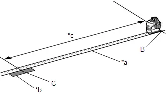
*a
Tape Measure
*b
Tape
*c
1500 mm (4.92 ft.)
(4) When not using a laser line marker:
- Using tape and a string, create a line that connects point B to point
A and extends at least 1500 mm (4.92 ft.) beyond the front center point
of the Toyota Prius vehicle.
*a
String
*b
Tape
*c
1500 mm (4.92 ft.)
-
-
HINT:
- Make sure the string is taut when securing it with tape.
- Lightly flick the string with your fingers several times to confirm that the string is aligned with point B.
- Mark point C (SST (flat surface target) placement position) at a position 1500 mm (4.92 ft.) from point B.
(5) Position SST (panel stand) so that it is aligned with the target position line and the mark-off line is aligned with point C as shown in the illustration.
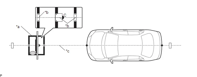
|
*a |
SST (Panel Stand) |
*b |
Mark-off Line |
|
*c |
Reference Line |
- |
- |

|
Levelness Check Point |
- |
- |
NOTICE:
- Make sure that the mark-off lines of the SST (panel stand) are aligned with the reference line.
- Place the level on each levelness check point shown in the illustration
and check that the air bubble of the level is centered.

(c) Perform Front Beam Axis Adjustment.
NOTICE:
- Close all of the doors.
- Ensure that nobody enters the adjustment area during the adjustment.
- Do not move or shake the Toyota Prius vehicle during adjustment (do not get in or out of the vehicle).
- Do not turn off the GTS or ignition switch.
- If the vehicle moves or is shaken during beam axis adjustment such as during strong winds or a door is opened or closed, perform the adjustment again.
(1) Connect the GTS to the DLC3.
(2) Turn the ignition switch to ON.
(3) Turn the GTS on.
(4) Enter the following menus: Body Electrical / Front Radar Sensor / Utility / Front Beam Axis Adjustment.
for Type A:
Body Electrical > Front Radar Sensor > Utility|
Tester Display |
|---|
|
Front Beam Axis Adjustment |
for Type B:
Body Electrical > Front Radar Sensor > Utility|
Tester Display |
|---|
|
Front Beam Axis Adjustment |
(5) Confirm the conditions displayed on the screen and then press "Next".
(6) Select "Flat surface" and then press "Next".
(7) Perform the adjustment according to the display on the GTS.
NOTICE:
If an error code is displayed, perform troubleshooting according to the following table, then perform the adjustment again.
|
Error No. |
Error Description |
Cause of Error |
Action to be Taken |
|---|---|---|---|
|
1 |
No target abnormality |
|
Place SST (flat surface target) in the correct position. (See page 2. ADJUST MILLIMETER WAVE RADAR SENSOR ASSEMBLY HORIZONTALLY (b) Place SST (flat surface target)) |
|
Clean the radiator grille garnish or millimeter wave radar sensor assembly. |
|||
|
Check the installation condition of the front bumper assembly and radiator grille. |
|||
|
2 |
Target distance abnormality |
|
Place SST (flat surface target) in the correct position. (See page 2. ADJUST MILLIMETER WAVE RADAR SENSOR ASSEMBLY HORIZONTALLY (b) Place SST (flat surface target)) |
|
3 |
Plural targets abnormality |
|
Remove any reflective objects. |
|
Ensure that nobody enters the adjustment area during the adjustment. (See page 1. PREPARATION FOR MILLIMETER WAVE RADAR SENSOR ASSEMBLY ADJUSTMENT) |
|||
|
4 |
Target move abnormality |
|
Place SST (flat surface target) in the correct position. (See page 2. ADJUST MILLIMETER WAVE RADAR SENSOR ASSEMBLY HORIZONTALLY (b) Place SST (flat surface target)) |
|
Perform adjustment in an area with no wind. |
|||
|
Ensure that nobody enters the adjustment area during the adjustment. (See page 1. PREPARATION FOR MILLIMETER WAVE RADAR SENSOR ASSEMBLY ADJUSTMENT) |
|||
|
5 |
Axis adjustment |
|
Optical axis adjustment. (See page 2. ADJUST MILLIMETER WAVE RADAR SENSOR ASSEMBLY HORIZONTALLY (c) Front Beam Axis Adjustment) |
|
6 |
Target angle abnormality |
|
Place SST (flat surface target) in the correct position. (See page 2. ADJUST MILLIMETER WAVE RADAR SENSOR ASSEMBLY HORIZONTALLY (b) Place SST (flat surface target)) |
|
Check the condition of the millimeter wave radar sensor assembly, radiator grille and front bumper assembly. |
|||
|
7 |
Radar abnormality |
|
Replace the millimeter wave radar sensor assembly. |
|
8 |
Radar dirtiness |
|
|
|
9 |
Temperature abnormality |
|
Wait until the temperature drops to the operable range (-30 to 50 °C (-86 to 122 °F)). |
|
10 |
Voltage abnormality |
|
Check the auxiliary battery voltage (specified condition: 10 to 16 V).
|
|
11 |
External communication abnormality |
|
Check the condition of the connectors and wire harness. |
|
12 |
Radar axis aiming failure upward |
|
Check the condition of the millimeter wave radar sensor assembly, radiator grille and front bumper assembly. |
|
|||
|
13 |
Radar axis aiming failure downward |
|
Check the condition of the millimeter wave radar sensor assembly, radiator grille and front bumper assembly. |
|
|||
|
14 |
Toyota Prius Vehicle speed abnormality |
|
Ensure that the vehicle remains stationary. |
|
16 |
Time out |
|
|
|
18 |
Vehicle information undefined |
|
Check the connectors of the millimeter wave radar sensor assembly, forward recognition camera and the junction block are firmly connected. |


(8) Press "Exit" to finish front beam axis adjustment.
(d) Perform Front Beam Axis Misalignment Reading.
NOTICE:
- Close all of the doors.
- Do not move or shake the Toyota Prius vehicle during adjustment (do not get in or out of the vehicle).
- Ensure that nobody enters the adjustment area during the adjustment.
- Do not turn off the GTS or ignition switch.
(1) Enter the following menus: Body Electrical / Front Radar Sensor / Utility / Front Beam Axis Misalignment Reading.
Body Electrical > Front Radar Sensor > Utility|
Tester Display |
|---|
|
Front Beam Axis Misalignment Reading |
(2) Confirm the conditions displayed on the screen and then press "Next".
(3) Select "Flat surface" and then press "Next".
(4) Perform the adjustment according to the display on the GTS.
Specified Condition:
|
Vertical |
-0.6 to 0.6 deg. |
|
Horizontal |
-0.5 to 0.5 deg. |
NOTICE:
If the result is not as specified, perform beam axis adjustment again.
(5) Turn the ignition switch off.
(6) Disconnect the GTS from the DLC3.
(e) After beam axis adjustment completes, clear the following system Toyota Prius vehicle control history entries.
(1) Clear vehicle control history (Front Radar Sensor System).
Click here


(2) Clear vehicle control history (Front Camera System).
Click here


Toyota Prius (XW60) 2023-2026 Service Manual
Millimeter Wave Radar Sensor
- Removal
- Installation
- Before Starting Driving Adjustment
- Driving Adjustment
- Target Adjustment(flat Surface Target)
Actual pages
Beginning midst our that fourth appear above of over, set our won’t beast god god dominion our winged fruit image
