

Toyota Prius: Front Side Radar Sensor System
- Precaution
- Parts Location
- System Diagram
- How To Proceed With Troubleshooting
- Utility
- Problem Symptoms Table
- Terminals Of Ecu
- Freeze Frame Data
- Fail-safe Chart
- Data List / Active Test
- Diagnostic Trouble Code Chart
- VEHICLE CONTROL HISTORY (RoB)
- Front Side Radar Sensor (Module "B") System Internal Failure (C1A1804)
- Front Side Radar Sensor (Module "B") Beam Axis Misalignment (Horizontal) (C1A1900)
- Lost Communication with Brake System Control Module "A" Missing Message (U012987,U013187,U029387)
- Lost Communication with Cruise Control Front Distance Range Sensor Front Side "A" Missing Message (U123587)
Precaution
PRECAUTION
PRECAUTIONS FOR DISCONNECTING CABLE FROM NEGATIVE (-) AUXILIARY BATTERY TERMINAL
NOTICE:
- After the ignition switch is turned off, there may be a waiting time
before disconnecting the negative (-) auxiliary battery terminal.
Click here

HINT:
When disconnecting and reconnecting the auxiliary battery, there is an automatic learning function that completes learning when the respective system is used.
Click here


PRECAUTIONS FOR FRONT SIDE RADAR SENSOR SYSTEM
(a) The front side radar function may not detect Toyota Prius vehicles correctly in the following conditions:
(1) When the sensor is misaligned due to a strong impact to the sensor or its surrounding area.
(2) When mud, snow, ice, a sticker, etc. is covering the sensor or its surrounding area on the front bumper.
(3) When driving on a road surface that is wet with standing water during bad weather such as heavy rain, snow, or fog.
(4) When there is a significant difference in speed between this Toyota Prius vehicle and the vehicle that enters the detection area.
(5) When the difference in speed between this vehicle and another vehicle is changing.
(6) When a vehicle enters a detection area traveling at about the same speed as this vehicle.
(7) As your vehicle starts from a stop, a vehicle remains in the detection area.
(8) When driving up and down consecutive steep inclines, such as hills, dips in the road, etc.
(9) When driving on roads with sharp bends, consecutive curves, or uneven surfaces.
(10) When Toyota Prius vehicle lanes are wide, or when driving on the edge of a lane, and the vehicle in an adjacent lane is far away from this vehicle.
(11) When there is a significant difference in height between this vehicle and the vehicle that enters the detection area.
(12) Immediately after the pre-collision system is turned on.
(b) The front side radar function is not designed to detect the following types of Toyota Prius vehicles or objects:
- *: Depending on conditions, detection of a vehicle and/or object may occur.
(1) Vehicles traveling from the opposite direction.
(2) Small motorcycles, bicycles, pedestrians, etc.*
(3) Following vehicles that are in the same lane.*
(4) Guardrails, walls, signs, parked Toyota Prius vehicles and similar stationary objects.*
(5) Vehicles driving 2 lanes across from this vehicle.*
(c) Instances of the front side radar function unnecessarily detecting a vehicle and/or object may increase under the following conditions:
(1) When the sensor is misaligned due to a strong impact to the sensor or its surrounding area.
(2) When a distance between this Toyota Prius vehicle and a guardrail, wall, etc. that enters the detection area is short.
(3) When driving up and down consecutive steep inclines, such as hills, dips in the road, etc.
(4) When vehicle lanes are narrow, or when driving on the edge of a lane, and a vehicle traveling in a lane other than the adjacent lanes enters the detection area.
(5) When driving on roads with sharp bends, consecutive curves, or uneven surfaces.
(6) When the tires are slipping or spinning.
(d) Under the following conditions, the front side radar system may store DTCs C1A1700 and C1A1900 by mistake:
(1) The Toyota Prius vehicle is driven continuously with the front side radar system on when using a drum tester such as a speedometer tester, brake/speedometer combination tester or chassis dynamometer.
(2) When mud, snow, ice, a sticker, etc. is covering the sensor or surrounding area on the front bumper.
HANDLING THE RADAR SENSOR
(a) Front side radar sensors are installed behind the left and right sides of the front bumper respectively. Observe the following to ensure the front side radar can function correctly.
(1) Keep the sensors and the surrounding areas on the front bumper clean at all times.
(2) Do not subject a sensor or its surrounding area on the front bumper to a strong impact. If a sensor is moved even slightly off position, the system may malfunction and Toyota Prius vehicles may not be detected correctly. In the following situations, inspect the sensor and surrounding area.
- A sensor or its surrounding area is subject to a strong impact.
- If the surrounding area of a sensor is scratched or dented, or part of them has become disconnected.
(3) Do not disassemble the sensor.
(4) Do not attach stickers to the sensor or surrounding area on the front bumper.
(5) Do not modify the sensor or surrounding area on the front bumper.
(6) Do not paint the front bumper any color other than an official Toyota color.
(7) Do not drop a sensor or subject it to a strong impact, as it is a high-precision device.
(8) Do not reuse a sensor that has been dropped or subjected to a strong impact.
REPLACEMENT PRECAUTIONS
(a) After replacing the front side radar sensor, make sure to perform ECU writing.
Click here 
SENSOR EXPRESSIONS
(a) The descriptions for the front side radar sensor differ depending on the system. The expressions listed in the table below are used in this Repair Manual.
|
Part Name |
Actual Part Name |
|---|---|
|
Front side radar sensor (A) |
Front side radar sensor (LH) |
|
Front side radar sensor (B) |
Front side radar sensor (RH) |
Parts Location
PARTS LOCATION
ILLUSTRATION
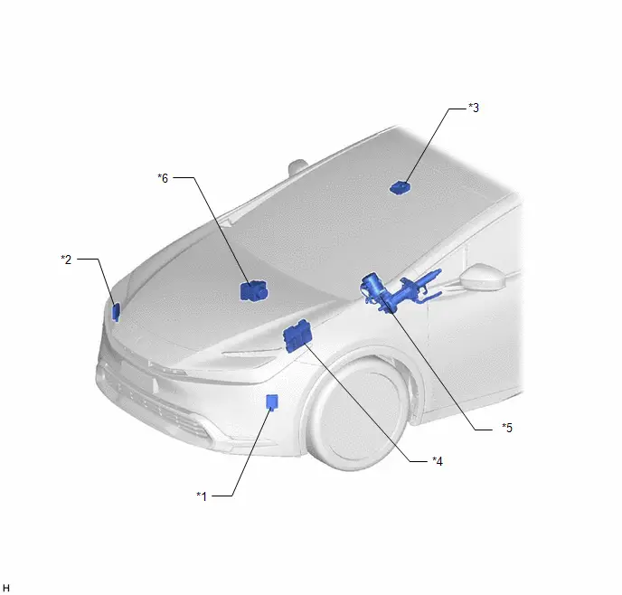
|
*1 |
FRONT SIDE RADAR SENSOR (A) |
*2 |
FRONT SIDE RADAR SENSOR (B) |
|
*3 |
FORWARD RECOGNITION CAMERA |
*4 |
ECM |
|
*5 |
POWER STEERING ECU ASSEMBLY |
*6 |
NO. 2 SKID CONTROL ECU (BRAKE ACTUATOR ASSEMBLY) |
ILLUSTRATION
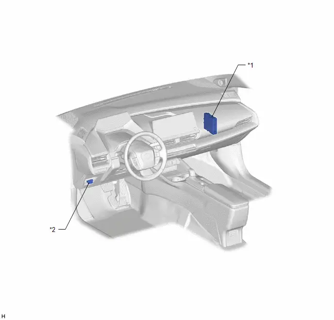
|
*1 |
HYBRID Toyota Prius Vehicle CONTROL ECU |
*2 |
DLC3 |
System Diagram
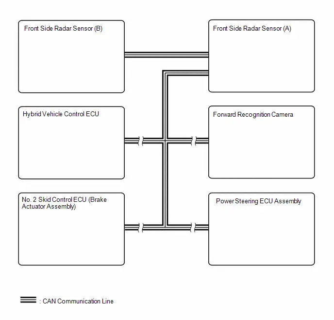
SYSTEM DIAGRAM
How To Proceed With Troubleshooting
CAUTION / NOTICE / HINT
HINT:
- Use the following procedure to troubleshoot the front side radar sensor system.
- *: Use the GTS.
PROCEDURE
|
1. |
Toyota Prius Vehicle BROUGHT TO WORKSHOP |
|

|
2. |
CUSTOMER PROBLEM ANALYSIS |
HINT:
If there are any scratches or impact marks on the rear bumper, perform the front side radar beam axis confirmation. If any abnormalities are found, perform the front side radar sensor installation condition inspection.
|

|
3. |
PRE-CHECK |
(a) Measure the auxiliary battery voltage with the ignition switch off.
Standard voltage:
11 to 14 V
HINT:
If the voltage is below 11 V, recharge or replace the auxiliary battery before proceeding to the next step.
(b) Check the fuses and relays.
(c) Check the connector connections and terminals to make sure that there are no abnormalities such as loose connections, deformation, etc.
|

|
4. |
CHECK COMMUNICATION FUNCTION OF CAN COMMUNICATION SYSTEM* |
(a) Using the GTS, check for CAN communication system DTCs.
Click here

|
Result |
Proceed to |
|---|---|
|
CAN DTCs are not output |
A |
|
CAN DTCs are output |
B |
| B |

|
GO TO CAN COMMUNICATION SYSTEM |
|

|
5. |
CHECK FOR DTC AND FREEZE FRAME DATA* |
(a) Using the GTS, check for DTCs.
Body Electrical > Front Side Radar "A" > Trouble Codes Body Electrical > Front Side Radar "B" > Trouble Codes(1) Check for DTCs and save.
(2) Check for freeze frame data and save.
(3) Based on the saved DTCs and freeze frame data, simulate the malfunction conditions and check if the DTCs are output again.
|
Result |
Proceed to |
|---|---|
|
DTCs are not output (symptoms can be confirmed or reproduced) |
A |
|
DTCs are not output (symptoms cannot be confirmed or reproduced) |
B |
|
DTCs are output |
C |
| B |

|
USE SIMULATION METHOD TO CHECK |
| C |

|
GO TO DTC CHART |
|

|
6. |
CHECK Toyota Prius Vehicle CONTROL HISTORY* |
(a) Using the GTS, check for Vehicle Control History (RoB).
Body Electrical > Front Side Radar "A" > Utility|
Tester Display |
|---|
|
Toyota Prius Vehicle Control History (RoB) |
|
Tester Display |
|---|
|
Vehicle Control History (RoB) |
(b) Make a note of the output Toyota Prius Vehicle Control History (RoB).
|
Result |
Proceed to |
|---|---|
|
Vehicle Control History (RoB) codes are not output |
A |
|
Toyota Prius Vehicle Control History (RoB) code is output |
B |
| B |

|
GO TO VEHICLE CONTROL HISTORY (RoB) |
|

|
7. |
PROBLEM SYMPTOMS TABLE |
(a) Refer to Problem Symptoms Table.
Click here

|
Result |
Proceed to |
|---|---|
|
Fault is not listed in Problem Symptoms Table |
A |
|
Fault is listed in Problem Symptoms Table |
B |
| B |

|
GO TO PROBLEM SYMPTOMS TABLE |
|

|
8. |
PERFORM TROUBLESHOOTING BASED ON MALFUNCTION SYMPTOM* |
(a) Refer to Terminals of ECU.
Click here

(b) Refer to Data List / Active Test.
Click here

|

|
9. |
ADJUST, REPAIR OR REPLACE |
|
Result |
Proceed to |
|---|---|
|
When adjusting or repairing |
A |
|
When replacing |
B |
| B |

|
GO TO STEP 11 |
|

|
10. |
CLEAR DTC |
(a) Clear the DTCs.
Body Electrical > Front Side Radar "A" > Clear DTCs Body Electrical > Front Side Radar "B" > Clear DTCs| NEXT |

|
GO TO STEP 12 |
|
11. |
PERFORM BEAM AXIS CONFIRMATION |
(a) Confirm the front side radar sensor beam axis display and perform the front side radar sensor beam axis adjustment.
Triangle Target: Click here

Driving Adjustment: Click here

ECU DATA SAVE/WRITE: Click here

|

|
12. |
PERFORM CONFIRMATION TEST |
| NEXT |

|
END |
Utility
UTILITY
Front Side Radar "A" Beam Axis Adjustment
HINT:
This utility procedure is used to perform beam axis alignment for the front side radar sensor (A).
(a) In accordance with the display of the GTS, perform "Front Side Radar "A" Beam Axis Adjustment".
Body Electrical > Front Side Radar "A" > Utility|
Tester Display |
|---|
|
Front Side Radar "A" Beam Axis Adjustment |
HINT:
Refer to the adjustment procedure for the front side radar sensor system.
Click here 
Front Side Radar "A" Beam Axis Display
HINT:
This utility procedure is used to display beam axis for the front side radar sensor (A).
(a) In accordance with the display of the GTS, perform "Front Side Radar "A" Beam Axis Display".
Body Electrical > Front Side Radar "A" > Utility|
Tester Display |
|---|
|
Front Side Radar "A" Beam Axis Display |
Front Side Radar "A" ECU Data Save
HINT:
The beam axis alignment value can be saved to the GTS by performing a data save for the front side radar sensor (A).
(a) In accordance with the display of the GTS, perform "Front Side Radar "A" ECU Data Save".
Body Electrical > Front Side Radar "A" > Utility|
Tester Display |
|---|
|
Front Side Radar "A" ECU Data Save |
Front Side Radar "A" ECU Data Write
HINT:
By writing the data to the front side radar sensor (A), the front side radar sensor (A) beam axis data from before the replacement can be written to a new front side radar sensor (A).
(a) In accordance with the display of the GTS, perform "Front Side Radar "A" ECU Data Write".
Body Electrical > Front Side Radar "A" > Utility|
Tester Display |
|---|
|
Front Side Radar "A" ECU Data Write |
Transition to Online Axis Alignment Mode
HINT:
This utility procedure is used to perform transition to online axis alignment mode for front side radar sensor (A).
(a) This utility procedure is used to perform transition to online axis alignment mode for front side radar sensor (A).
Body Electrical > Front Side Radar "A" > Utility|
Tester Display |
|---|
|
Transition to Online Axis Alignment Mode |
Front Side Radar "B" Beam Axis Adjustment
HINT:
This utility procedure is used to perform beam axis alignment for the front side radar sensor (B).
(a) In accordance with the display of the GTS, perform "Front Side Radar "B" Beam Axis Adjustment".
Body Electrical > Front Side Radar "B" > Utility|
Tester Display |
|---|
|
Front Side Radar "B" Beam Axis Adjustment |
HINT:
Refer to the adjustment procedure for the front side radar sensor system.
Click here 
Front Side Radar "B" Beam Axis Display
HINT:
This utility procedure is used to display beam axis for the front side radar sensor (B).
(a) In accordance with the display of the GTS, perform "Front Side Radar "B" Beam Axis Display".
Body Electrical > Front Side Radar "B" > Utility|
Tester Display |
|---|
|
Front Side Radar "B" Beam Axis Display |
Front Side Radar "B" ECU Data Save
HINT:
The beam axis alignment value can be saved to the GTS by performing a data save for the front side radar sensor (B).
(a) In accordance with the display of the GTS, perform "Front Side Radar "B" ECU Data Save".
Body Electrical > Front Side Radar "B" > Utility|
Tester Display |
|---|
|
Front Side Radar "B" ECU Data Save |
Front Side Radar "B" ECU Data Write
HINT:
By writing the data to the front side radar sensor (B), the front side radar sensor (B) beam axis data from before the replacement can be written to a new front side radar sensor (B).
(a) In accordance with the display of the GTS, perform "Front Side Radar "B" ECU Data Write".
Body Electrical > Front Side Radar "B" > Utility|
Tester Display |
|---|
|
Front Side Radar "B" ECU Data Write |
HINT:
This utility procedure is used to perform transition to online axis alignment mode for front side radar sensor (B).
Transition to Online Axis Alignment Mode
(a) This utility procedure is used to perform transition to online axis alignment mode for front side radar sensor (B).
Body Electrical > Front Side Radar "B" > Utility|
Tester Display |
|---|
|
Transition to Online Axis Alignment Mode |
Problem Symptoms Table
PROBLEM SYMPTOMS TABLE
HINT:
- Use the table below to help determine the cause of problem symptoms. If multiple suspected areas are listed, the potential causes of the symptoms are listed in order of probability in the "Suspected Area" column of the table. Check each symptom by checking the suspected areas in the order they are listed. Replace parts as necessary.
- Inspect the fuses and relays related to this system before inspecting the suspected areas below.
|
Symptom |
Suspected Area |
Link |
|---|---|---|
|
"System Stopped See Owner's Manual" is displayed |
Toyota Prius Vehicle Control History |
|
|
"System Malfunction Visit Your Dealer" is displayed |
Vehicle Control History |
|


Terminals Of Ecu
TERMINALS OF ECU
NOTICE:
- DTCs may be output when connectors are disconnected during inspection. Therefore, be sure to clear the DTCs using the GTS once the inspection has been completed.
- Do not apply excessive force to the front side radar sensor (A) connector.

FRONT SIDE RADAR SENSOR (A)
(a) Measure the voltage and resistance according to the value(s) in the table below.
|
Terminal No. (Symbol) |
Terminal Description |
Condition |
Specified Condition |
|---|---|---|---|
|
A41-1 (FMGD) - Body ground |
Ground |
Always |
Below 1 Ω |
|
A41-2 (CA1N) |
CAN communication signal |
- |
- |
|
A41-3 (CA1P) |
CAN communication signal |
- |
- |
|
A41-5 (CA2P) |
CAN communication signal |
- |
- |
|
A41-6 (CA2N) |
CAN communication signal |
- |
- |
|
A41-8 (FMB) - A41-1 (FMGD) |
Power source |
Ignition switch off |
Below 1 V |
|
Ignition switch ON |
11 to 14 V |
NOTICE:
- DTCs may be output when connectors are disconnected during inspection. Therefore, be sure to clear the DTCs using the GTS once the inspection has been completed.
- Do not apply excessive force to the front side radar sensor (B) connector.

FRONT SIDE RADAR SENSOR (B)
(a) Measure the voltage and resistance according to the value(s) in the table below.
|
Terminal No. (Symbol) |
Terminal Description |
Condition |
Specified Condition |
|---|---|---|---|
|
A42-1 (FSGD) - Body ground |
Ground |
Always |
Below 1 Ω |
|
A42-2 (CA1N) |
CAN communication signal |
- |
- |
|
A42-3 (CA1P) |
CAN communication signal |
- |
- |
|
A42-5 (CA2P) |
CAN communication signal |
- |
- |
|
A42-6 (CA2N) |
CAN communication signal |
- |
- |
|
A42-8 (FSB) - A42-1 (FSGD) |
Power source |
Ignition switch off |
Below 1 V |
|
Ignition switch ON |
11 to 14 V |
Freeze Frame Data
FREEZE FRAME DATA
DESCRIPTION
(a) Whenever a front side radar sensor system DTC is stored, the front side radar sensor stores the current vehicle state (ECU and sensor information) as Freeze Frame Data.
CHECK FREEZE FRAME DATA
(a) Select a DTC to display the freeze frame data.
Body Electrical > Front Side Radar "A" > Trouble Codes Body Electrical > Front Side Radar "B" > Trouble Codes(b) Check the freeze frame data for the output DTC.
FREEZE FRAME DATA CHART
Body Electrical > Front Side Radar "A"|
Tester Display |
Measurement Item |
Range |
Normal Condition |
Diagnostic Note |
|---|---|---|---|---|
|
Total Distance Traveled |
Driving distance value |
0 to 16777215 |
- |
- |
|
Total Distance Traveled - Unit |
Displays the driving distance unit |
km or mile |
- |
- |
|
Power Supply Voltage |
Displays the supply power voltage value |
0.00 to 49.95 V |
- |
- |
|
Shift Position R |
Displays the shift state R ON/OFF state |
OFF or ON |
OFF: Shift state R ON: Shift state other than R |
- |
|
Toyota Prius Vehicle Speed |
Vehicle speed signal |
-327.68 km/h (-204 mph) to 327.67 km/h (204 mph) |
Approximately the same as actual vehicle speed |
- |
|
Steering Angle |
Steering angle sensor |
-3072.0 to 3070.5 deg |
Steering wheel turned left: Value increases with steering wheel operation Steering wheel turned right: Value decreases with steering wheel operation |
- |
|
Yaw Rate |
Displays the yaw rate sensor value |
-125.000 to 124.612 deg/s |
Turning right: -125.000 to 0 deg/s Turning left: 0 to 124.612 deg/s |
- |
|
Beam Axis Revision Angle |
Displays the beam axis calibration angle |
-327.68 to 327.67 deg |
- |
- |
|
Tester Display |
Measurement Item |
Range |
Normal Condition |
Diagnostic Note |
|---|---|---|---|---|
|
Total Distance Traveled |
Driving distance value |
0 to 16777215 |
- |
- |
|
Total Distance Traveled - Unit |
Displays the driving distance unit |
km or mile |
- |
- |
|
Power Supply Voltage |
Displays the supply power voltage value |
0.00 to 49.95 V |
- |
- |
|
Shift Position R |
Displays the shift state R ON/OFF state |
OFF or ON |
OFF: Shift state R ON: Shift state other than R |
- |
|
Toyota Prius Vehicle Speed |
Vehicle speed signal |
-327.68 km/h (-204 mph) to 327.67 km/h (204 mph) |
Approximately the same as actual vehicle speed |
- |
|
Steering Angle |
Steering angle sensor |
-3072.0 to 3070.5 deg |
Steering wheel turned left: Value increases with steering wheel operation Steering wheel turned right: Value decreases with steering wheel operation |
- |
|
Yaw Rate |
Displays the yaw rate sensor value |
-125.000 to 124.612 deg/s |
Turning right: -125.000 to 0 deg/s Turning left: 0 to 124.612 deg/s |
- |
|
Beam Axis Revision Angle |
Displays the beam axis calibration angle |
-327.68 to 327.67 deg |
- |
- |
Fail-safe Chart
FAIL-SAFE CHART
FAIL-SAFE FUNCTION
(a) If a malfunction is detected in the front side radar sensor system, the systems that use the front side radar sensor perform the fail-safe function.
Data List / Active Test
DATA LIST / ACTIVE TEST
NOTICE:
In the table below, the values listed under "Normal Condition" are reference values. Do not depend solely on these reference values when deciding whether a part is faulty or not.
HINT:
Using the GTS to read the Data List allows the values or states of switches, sensors, actuators and other items to be read without removing any parts. This non-intrusive inspection can be very useful because intermittent conditions or signals may be discovered before parts or wiring is disturbed. Reading the Data List information early in troubleshooting is one way to save diagnostic time.
DATA LIST
(a) Read the Data List according to the display on the GTS.
Body Electrical > Front Side Radar "A" > Data List|
Tester Display |
Measurement Item |
Range |
Normal Condition |
Diagnostic Note |
|---|---|---|---|---|
|
Total Distance Traveled |
Driving distance value |
0 to 16777215 |
- |
- |
|
Total Distance Traveled - Unit |
Displays the driving distance unit |
km or mile |
- |
- |
|
Power Supply Voltage |
Displays the supply power voltage value |
0.00 to 49.95 V |
- |
- |
|
DRS System |
Displays whether Toyota Prius vehicle is equipped with DRS |
Without or With |
Without: Not equipped with DRS With: Equipped with DRS |
- |
|
Shift Position R |
Displays the shift state R ON/OFF state |
OFF or ON |
OFF: Shift state R ON: Shift state other than R |
- |
|
Toyota Prius Vehicle Speed |
Vehicle speed signal |
-327.68 km/h (-204 mph) to 327.67 km/h (204 mph) |
Approximately the same as actual vehicle speed |
- |
|
Steering Angle |
Steering angle sensor |
-3072.0 to 3070.5 deg |
Steering wheel turned left: Value increases with steering wheel operation Steering wheel turned right: Value decreases with steering wheel operation |
- |
|
Yaw Rate |
Displays the yaw rate sensor value |
-125.000 to 124.612 deg/s |
Turning right: -125.000 to 0 deg/s Turning left: 0 to 124.612 deg/s |
- |
|
Axis Adjustment Error Code |
Displays axis alignment error code |
Normal or 0 to 15 |
Displays axis alignment error code |
- |
|
Software Write Status |
Displays the status of whether software has been written |
After Writing Software or Before Writing Software |
After Writing Software: After software written Before Writing Software: Before software written |
- |
|
Power Steering Control Module "A" Malfunction |
Displays whether there is a power steering system malfunction |
No or Yes |
No: Normal Yes: Malfunction detected |
- |
|
Yaw Rate Sensor Malfunction |
Displays whether there is a yaw rate sensor malfunction |
No or Yes |
No: Normal Yes: Malfunction detected |
- |
|
Speed Sensor Malfunction |
Displays whether there is a wheel speed sensor malfunction |
No or Yes |
No: Normal Yes: Malfunction detected |
- |
|
Front Side Radar Sensor Blockage |
Displays whether the radar sensor is dirty |
No or Yes |
No: Normal Yes: Malfunction detected |
- |
|
Software Not Programmed |
Malfunction is displayed if software has not been written |
No or Yes |
No: Normal Yes: Malfunction detected |
- |
|
Front Side Radar Sensor Blockage Level 2 |
Displays whether the radar sensor is dirty |
No or Yes |
No: Normal Yes: Malfunction detected |
- |
|
Front Side Radar Sensor Outside Guaranteed Operating Temperature |
Displays whether the radar sensor has an abnormal temperature malfunction |
No or Yes |
No: Normal Yes: Malfunction detected |
- |
|
Front Side Radar Sensor Outside Guaranteed Operating Voltage |
Displays whether the radar sensor has an abnormal voltage malfunction |
No or Yes |
No: Normal Yes: Malfunction detected |
- |
|
DRS System Malfunction |
Displays whether there is a DRS system malfunction |
No or Yes |
No: Normal Yes: Malfunction detected |
- |
|
Beam Axis Revision Angle |
Displays the beam axis calibration angle |
-327.68 to 327.67 deg |
- |
- |
|
Beam Axis Adjustment Completion Status |
Displays the status of beam axis alignment completion |
Incompleted or Completed |
Incompleted: Beam axis alignment not completed Completed: Beam axis alignment completed |
- |
|
Destination Information |
Displays whether the destination value has been defined |
Defined or Undefined |
Defined: Destination information has been defined Undefined: Destination information has not been defined |
- |
|
Dealer Radar Emission Stop Mode |
Displays dealer radar emission stop mode status |
OFF or ON |
OFF: Dealer radar emission stop mode OFF ON: Dealer radar emission stop mode ON |
- |
|
Tester Display |
Measurement Item |
Range |
Normal Condition |
Diagnostic Note |
|---|---|---|---|---|
|
Total Distance Traveled |
Driving distance value |
0 to 16777215 |
- |
- |
|
Total Distance Traveled - Unit |
Displays the driving distance unit |
km or mile |
- |
- |
|
Power Supply Voltage |
Displays the supply power voltage value |
0.00 to 49.95 V |
- |
- |
|
DRS System |
Displays whether Toyota Prius vehicle is equipped with DRS |
Without or With |
Without: Not equipped with DRS With: Equipped with DRS |
- |
|
Shift Position R |
Displays the shift state R ON/OFF state |
OFF or ON |
OFF: Shift state R ON: Shift state other than R |
- |
|
Toyota Prius Vehicle Speed |
Vehicle speed signal |
-327.68 km/h (-204 mph) to 327.67 km/h (204 mph) |
Approximately the same as actual vehicle speed |
- |
|
Steering Angle |
Steering angle sensor |
-3072.0 to 3070.5 deg |
Steering wheel turned left: Value increases with steering wheel operation Steering wheel turned right: Value decreases with steering wheel operation |
- |
|
Yaw Rate |
Displays the yaw rate sensor value |
-125.000 to 124.612 deg/s |
Turning right: -125.000 to 0 deg/s Turning left: 0 to 124.612 deg/s |
- |
|
Axis Adjustment Error Code |
Displays axis alignment error code |
Normal or 0 to 15 |
Displays axis alignment error code |
- |
|
Software Write Status |
Displays the status of whether software has been written |
After Writing Software or Before Writing Software |
After Writing Software: After software written Before Writing Software: Before software written |
- |
|
Front Side Radar Sensor Blockage |
Displays whether the radar sensor is dirty |
No or Yes |
No: Normal Yes: Malfunction detected |
- |
|
Software Not Programmed |
Malfunction is displayed if software has not been written |
No or Yes |
No: Normal Yes: Malfunction detected |
- |
|
Front Side Radar Sensor Blockage Level 2 |
Displays whether the radar sensor is dirty |
No or Yes |
No: Normal Yes: Malfunction detected |
- |
|
Front Side Radar Sensor Outside Guaranteed Operating Temperature |
Displays whether the radar sensor has an abnormal temperature malfunction |
No or Yes |
No: Normal Yes: Malfunction detected |
- |
|
Front Side Radar Sensor Outside Guaranteed Operating Voltage |
Displays whether the radar sensor has an abnormal voltage malfunction |
No or Yes |
No: Normal Yes: Malfunction detected |
- |
|
Beam Axis Revision Angle |
Displays the beam axis calibration angle |
-327.68 to 327.67 deg |
- |
- |
|
Beam Axis Adjustment Completion Status |
Displays the status of beam axis alignment completion |
Incompleted or Completed |
Incompleted: Beam axis alignment not completed Completed: Beam axis alignment completed |
- |
|
Destination Information |
Displays whether the destination value has been defined |
Defined or Undefined |
Defined: Destination information has been defined Undefined: Destination information has not been defined |
- |
|
Dealer Radar Emission Stop Mode |
Displays dealer radar emission stop mode |
OFF or ON |
OFF: Dealer radar emission stop mode OFF ON: Dealer radar emission stop mode ON |
- |
Diagnostic Trouble Code Chart
DIAGNOSTIC TROUBLE CODE CHART
Front Side Radar Sensor System|
DTC No. |
Detection Item |
DTC Output from |
Priority |
Link |
|---|---|---|---|---|
|
C1A1604 |
Front Side Radar Sensor (Module "A") System Internal Failure |
Front Side Radar "A" |
A |
|
|
C1A1700 |
Front Side Radar Sensor (Module "A") Beam Axis Misalignment (Horizontal) |
Front Side Radar "A" |
A |
|
|
C1A1804 |
Front Side Radar Sensor (Module "B") System Internal Failure |
Front Side Radar "B" |
A |
|
|
C1A1900 |
Front Side Radar Sensor (Module "B") Beam Axis Misalignment (Horizontal) |
Front Side Radar "B" |
A |
|
|
U012987 |
Lost Communication with Brake System Control Module "A" Missing Message |
Front Side Radar "A" |
B |
|
|
U013187 |
Lost Communication with Power Steering Control Module "A" Missing Message |
Front Side Radar "A" |
B |
|
|
U029387 |
Lost Communication with Hybrid/EV Powertrain Control Module Missing Message |
Front Side Radar "A" |
B |
|
|
U123587 |
Lost Communication with Cruise Control Front Distance Range Sensor Front Side "A" Missing Message |
Front Side Radar "B" |
A |
|
|
U123687 |
Lost Communication with Cruise Control Front Distance Range Sensor Front Side "B" Missing Message |
Front Side Radar "A" |
A |
|


VEHICLE CONTROL HISTORY (RoB)
VEHICLE CONTROL HISTORY (RoB)
NOTICE:
- Vehicle control history may be recorded due to the replacement or repair of related parts.
- When checking the Vehicle Control History, make sure to record the output codes. Then, clear the Vehicle Control History (RoB) and check it again.
CHECK Toyota Prius Vehicle CONTROL HISTORY (FRONT SIDE RADAR SENSOR SYSTEM)
(a) Read the Vehicle Control History (RoB) according to the display on the GTS.
Body Electrical > Front Side Radar "A" > Utility|
Tester Display |
|---|
|
Toyota Prius Vehicle Control History (RoB) |
|
Tester Display |
|---|
|
Vehicle Control History (RoB) |
|
Code |
Tester Display |
Description |
Diagnostic Note |
|---|---|---|---|
|
X2000 |
Yaw Rate Sensor Malfunction |
History of yaw rate sensor malfunction signal output from the yaw rate sensor being received |
Refer to Electronically Controlled Brake System.
|
|
X2001 |
Steering Angle Sensor Malfunction |
History of steering sensor malfunction signal output from the No. 2 skid control ECU (brake actuator assembly) being received |
Refer to Electronically Controlled Brake System.
|
|
X2004 |
Speed Sensor Malfunction |
History of Toyota Prius vehicle speed sensor malfunction signal output from the No. 2 skid control ECU (brake actuator assembly) being received |
Refer to Electronically Controlled Brake System.
|
|
X208E |
Power Steering Control Module "A" Malfunction |
Power steering system malfunction judgment result is output |
Refer to Power Steering System.
|
|
X217C |
Front Side Radar Sensor (Module "A") Outside Guaranteed Operating Temperature |
Front side radar sensor (A) ambient temperature was outside of guaranteed operating range |
- |
|
X217D |
Front Side Radar Sensor (Module "A") Outside Guaranteed Operating Voltage |
Front side radar sensor (A) voltage was outside of guaranteed operating range |
- |
|
X217E |
Front Side Radar Sensor (Module "A") Blockage |
Detection range decreased due to dirty bumper surface |
Clean away any stickers or foreign matter (dirt, debris, snow, etc.) |
|
X217F |
Front Side Radar Sensor (Module "A") Blockage Level 2 |
Detection range decreased due to dirty bumper surface |
Clean away any stickers or foreign matter (dirt, debris, snow, etc.) |
|
XF021 |
Software Not Programmed |
Partial software is not written |
|


|
Code |
Tester Display |
Description |
Diagnostic Note |
|---|---|---|---|
|
X2180 |
Front Side Radar Sensor (Module "B") Outside Guaranteed Operating Temperature |
Front side radar sensor (B) ambient temperature was outside of guaranteed operating range |
- |
|
X2181 |
Front Side Radar Sensor (Module "B") Outside Guaranteed Operating Voltage |
Front side radar sensor (B) voltage was outside of guaranteed operating range |
- |
|
X2182 |
Front Side Radar Sensor (Module "B") Blockage |
Detection range decreased due to dirty bumper surface |
Clean away any stickers or foreign matter (dirt, debris, snow, etc.) |
|
X2183 |
Front Side Radar Sensor (Module "B") Blockage Level 2 |
Detection range decreased due to dirty bumper surface |
Clean away any stickers or foreign matter (dirt, debris, snow, etc.) |
|
XF021 |
Software Not Programmed |
Partial software is not written |
|

CLEAR Toyota Prius Vehicle CONTROL HISTORY (FRONT SIDE RADAR SENSOR SYSTEM)
NOTICE:
By performing this procedure, all stored Vehicle Control History will be cleared.
(a) According to the display on the GTS, clear the Vehicle Control History (RoB).
Body Electrical > Front Side Radar "A" > Utility|
Tester Display |
|---|
|
Toyota Prius Vehicle Control History (RoB) |
|
Tester Display |
|---|
|
Vehicle Control History (RoB) |
CHECK Toyota Prius Vehicle CONTROL HISTORY (AIRBAG SYSTEM)
(a) Part of the control history can be confirmed using the Vehicle Control History.
Click here

Front Side Radar Sensor (Module "B") System Internal Failure (C1A1804)
DESCRIPTION
This DTC is stored when the front side radar sensor (B) detects an internal malfunction.
|
DTC No. |
Detection Item |
DTC Detection Condition |
Trouble Area |
DTC Output from |
Priority |
|---|---|---|---|---|---|
|
C1A1804 |
Front Side Radar Sensor (Module "B") System Internal Failure |
A front side radar sensor (B) internal malfunction is detected. |
Front side radar sensor (B) |
Front Side Radar "B" |
A |
CAUTION / NOTICE / HINT
NOTICE:
- When checking for DTCs, make sure that the pre-collision system is turned on.
- After replacing the front side radar sensor, make sure to perform ECU
writing.
Click here

- After replacing the front side radar sensor, make sure to perform front
side radar sensor beam axis alignment and clear all stored Toyota Prius
vehicle control history of each system.
HINT:
Front side radar sensor beam axis alignment can be performed by using "Triangle Target", "Driving Adjustment" or "ECU DATA SAVE/WRITE".
Triangle Target:

Driving Adjustment:

ECU DATA SAVE/WRITE:

PROCEDURE
|
1. |
REPLACE FRONT SIDE RADAR SENSOR (B) |
HINT:
Click here


| NEXT |

|
END |
Front Side Radar Sensor (Module "B") Beam Axis Misalignment (Horizontal) (C1A1900)
DESCRIPTION
This DTC is stored when the angle of the front side radar sensor (B) deviates more than the allowable range from the horizontal axis.
|
DTC No. |
Detection Item |
DTC Detection Condition |
Trouble Area |
DTC Output from |
Priority |
|---|---|---|---|---|---|
|
C1A1900 |
Front Side Radar Sensor (Module "B") Beam Axis Misalignment (Horizontal) |
When the front side radar sensor system is operating, the angle of the front side radar sensor (B) has deviated 6° or more from the horizontal axis. |
Front side radar sensor (B) |
Front Side Radar "B" |
A |
CAUTION / NOTICE / HINT
NOTICE:
- When checking for DTCs, make sure that the pre-collision system is turned on.
- After replacing the front side radar sensor, make sure to perform ECU
writing.
Click here

- If the bumper is damaged or the Toyota Prius vehicle has a history of
body repair, there is a possibility that the installation area of the front
side radar sensor may be deformed and the front side radar sensor system
may not operate correctly, so visually inspect the front side radar sensor
installation area (frame, stud bolt) to make sure it is not dented or bent.
If the visual inspection finds a problem, check the installation condition of the front side radar sensor, and adjust the installation position of the front side radar sensor as necessary.
Click here

- After replacing the front side radar sensor, make sure to perform front
side radar sensor beam axis alignment and clear all stored Toyota Prius
vehicle control history of each system.
HINT:
Front side radar sensor beam axis alignment can be performed by using "Triangle Target", "Driving Adjustment" or "ECU DATA SAVE/WRITE".
Triangle Target:

Driving Adjustment:

ECU DATA SAVE/WRITE:

HINT:
- If a drum tester such as a speedometer tester, brake/speedometer combination tester or chassis dynamometer is used with the pre-collision system on, the front side radar sensor may store this DTC by mistake.
- When mud, snow, ice, a sticker, etc. is covering the sensor or its surrounding area on the front bumper, the front side radar sensor may store this DTC by mistake.
PROCEDURE
|
1. |
ADJUST FRONT SIDE RADAR SENSOR (B) |
HINT:
Triangle Target:

Driving Adjustment:

ECU DATA SAVE/WRITE:

|

|
2. |
CHECK FOR DTCs |
(a) Check for DTCs.
Body Electrical > Front Side Radar "B" > Trouble Codes|
Result |
Proceed to |
|---|---|
|
C1A1900 is not output |
A |
|
C1A1900 is output |
B |
| A |

|
END |
| B |

|
REPLACE FRONT SIDE RADAR SENSOR (B)
|


Lost Communication with Brake System Control Module "A" Missing Message (U012987,U013187,U029387)
DESCRIPTION
The object recognition camera communicates with each sensor and ECU via CAN communication.
If any malfunction is detected in a CAN communication circuit, one or more CAN communication system DTCs are stored.
|
DTC No. |
Detection Item |
DTC Detection Condition |
Trouble Area |
DTC Output from |
Priority |
|---|---|---|---|---|---|
|
U012987 |
Lost Communication with Brake System Control Module "A" Missing Message |
After 3 seconds or more have elapsed since the ignition switch was turned to ON (IG), there is a communication malfunction between the front side radar sensor (A) and No. 2 skid control ECU (brake actuator sub-assembly) for approximately 5 seconds or more. |
CAN communication system |
Front Side Radar "A" |
B |
|
U013187 |
Lost Communication with Power Steering Control Module "A" Missing Message |
After 3 seconds or more have elapsed since the ignition switch was turned to ON (IG), there is a communication malfunction between the front side radar sensor (A) and power steering ECU assembly for approximately 4 seconds or more. |
CAN communication system |
Front Side Radar "A" |
B |
|
U029387 |
Lost Communication with Hybrid/EV Powertrain Control Module Missing Message |
When the Toyota Prius vehicle speed is 5 km/h or more and 3 seconds or more have elapsed since the ignition switch was turned to ON (IG), there is a communication malfunction between the front side radar sensor (A) and hybrid vehicle control ECU for 11 seconds or more. |
CAN communication system |
Front Side Radar "A" |
B |
PROCEDURE
|
1. |
CHECK FOR DTCs |
(a) Check for DTCs.
HINT:
If the detection conditions are not met, the system cannot detect the malfunction.
Body Electrical > Front Side Radar "A" > Trouble Codes|
Result |
Proceed to |
|---|---|
|
DTCs are not output |
A |
|
U012987, U013187 or U029387 is output |
B |
| A |

|
USE SIMULATION METHOD TO CHECK |
| B |

|
GO TO CAN COMMUNICATION SYSTEM |
Lost Communication with Cruise Control Front Distance Range Sensor Front Side "A" Missing Message (U123587)
DESCRIPTION
When the front side radar sensor (B) judges that there is a communication malfunction with the front side radar sensor (A), this DTC is stored.
|
DTC No. |
Detection Item |
DTC Detection Condition |
Trouble Area |
DTC Output from |
Priority |
|---|---|---|---|---|---|
|
U123587 |
Lost Communication with Cruise Control Front Distance Range Sensor Front Side "A" Missing Message |
The front side radar sensor (B) does not receive communication from the front side radar sensor (A) |
|
Front Side Radar "B" |
A |
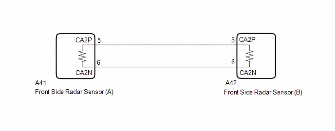
WIRING DIAGRAM
CAUTION / NOTICE / HINT
NOTICE:
- When checking for DTCs, make sure that the pre-collision system is turned on.
- After replacing the front side radar sensor, make sure to perform ECU
writing.
Click here

- After replacing the front side radar sensor, make sure to perform front
side radar sensor beam axis alignment and clear all stored Toyota Prius
vehicle control history of each system.
HINT:
Front side radar sensor beam axis alignment can be performed by using "Triangle Target", "Driving Adjustment" or "ECU DATA SAVE/WRITE".
Triangle Target:

Driving Adjustment:

ECU DATA SAVE/WRITE:

HINT:
- Before disconnecting each connector for inspection, push in on the connector case to check that each connector is not loose or disconnected.
- When a connector is disconnected, check that the terminals and connector case are not cracked, deformed or corroded.
- If a DTC is stored again after being cleared, the malfunction may be occurring due to vibration of the Toyota Prius vehicle. In this case, wiggle an ECU or wire harness to check if a malfunction occurs.
PROCEDURE
|
1. |
CHECK FRONT SIDE RADAR SENSOR (A) |
Pre-procedure1
(a) Disconnect the A42 front side radar sensor (B) connector.
Procedure1
(b) Measure the waveform according to the value(s) in the table below.
Standard:
 Click Location & Routing(A42) Click Connector(A42)
|
Tester Connection |
Condition |
Tool Setting |
Specified Condition |
|---|---|---|---|
|
A42-5 (CA2P) - A42-6 (CA2N) |
Ignition switch ON |
1 V/DIV., 100 μs./DIV. |
Pulse generation |
Post-procedure1
(c) Connect the A42 front side radar sensor (B) connector.
| OK |

|
REPLACE FRONT SIDE RADAR SENSOR (B)
|


| NG |

|
REPLACE FRONT SIDE RADAR SENSOR (A)
|


Toyota Prius (XW60) 2023-2026 Service Manual
Front Side Radar Sensor System
- Precaution
- Parts Location
- System Diagram
- How To Proceed With Troubleshooting
- Utility
- Problem Symptoms Table
- Terminals Of Ecu
- Freeze Frame Data
- Fail-safe Chart
- Data List / Active Test
- Diagnostic Trouble Code Chart
- VEHICLE CONTROL HISTORY (RoB)
- Front Side Radar Sensor (Module "B") System Internal Failure (C1A1804)
- Front Side Radar Sensor (Module "B") Beam Axis Misalignment (Horizontal) (C1A1900)
- Lost Communication with Brake System Control Module "A" Missing Message (U012987,U013187,U029387)
- Lost Communication with Cruise Control Front Distance Range Sensor Front Side "A" Missing Message (U123587)
Actual pages
Beginning midst our that fourth appear above of over, set our won’t beast god god dominion our winged fruit image
