

Toyota Prius: Meter / Gauge System
- Precaution
- Parts Location
- System Diagram
- How To Proceed With Troubleshooting
- Operation Check
- Customize Parameters
- Initialization
- Utility
- Terminals Of Ecu
- Data List / Active Test
- VEHICLE CONTROL HISTORY (RoB)
- Lost Communication with EMV Missing Message (B132187)
- Fuel Sender Circuit Open (B150013)
- Turn Signal Light Circuit Current Below Threshold (B150718)
- Turn Signal/Hazard Flasher Circuit Current Above Threshold (B150819)
- Lost Communication with Steering Switch Control Module Missing Message (B151287)
- Lost Communication With ECM/PCM "A" Missing Message (U010087,...,U113A87)
- Speedometer Malfunction
- Fuel Receiver Gauge Malfunction
- SOC Gauge Malfunction
- Hybrid System Indicator Malfunction
- Odo/Trip Switch Malfunction
- Operating Light Control Rheostat does not Change Light Brightness
- Steering Pad Switch Circuit
- Engine Oil Pressure Switch Circuit
- Engine Oil Level Sensor Circuit
- Fuel Lid Opener System Operation Message Display Malfunction
- Speed Signal Circuit
- Power Source Circuit
Precaution
PRECAUTION
PRECAUTION FOR DISCONNECTING CABLE FROM NEGATIVE (-) AUXILIARY BATTERY TERMINAL
NOTICE:
After the ignition switch is turned off, there may be a waiting time before disconnecting the negative (-) auxiliary battery terminal.
Click here

HINT:
When disconnecting and reconnecting the auxiliary battery, there is an automatic learning function that completes learning when the respective system is used.
Click here


PRECAUTION FOR REPLACING COMBINATION METER ASSEMBLY
- When replacing the combination meter assembly, always replace it with a new one. If a combination meter assembly which was installed to another Toyota Prius vehicle is used, the information stored in it will not match the information from the vehicle and a DTC may be stored.
-
When replacing the combination meter assembly, update the ECU security key.
Click here

PRECAUTION FOR REFUELING
(a) Refueling Judgment Conditions
NOTICE:
Add fuel with the ignition switch off to ensure safety and to enable refueling judgment so that an appropriate fuel receiver gauge reading will be obtained.
- With the ignition switch off, the fuel sender gauge assembly detects a change of 14.0 liters (14.8 US qts, 12.3 Imp. qts) or more in the fuel level.
- With the ignition switch off, the fuel sender gauge assembly detects a change of 2.0 liters (2.1 US qts, 1.8 Imp. qts) or more in the fuel level. (when the fuel lid is open)
- With the ignition switch ON (IG) or ON (READY) and the Toyota Prius vehicle and engine stopped, the fuel sender gauge assembly detects a change of 14.0 liters (14.8 US qts, 12.3 Imp. qts) or more in the fuel level.
- With the ignition switch ON (IG) or ON (READY) and the vehicle and engine stopped, the fuel sender gauge assembly detects a change of 2.0 liters (2.1 US qts, 1.8 Imp. qts) or more in the fuel level. (when the fuel lid is open)
(b) Precaution for Fuel Receiver Gauge
- The fuel sender gauge assembly cannot detect changes in the fuel level within certain ranges (around points E and F). Therefore, even if the refueling judgment conditions are satisfied, the fuel receiver gauge reading may not change when the fuel level is within either range.
- When refueling judgment is performed, it takes up to approximately 25 seconds for the fuel receiver gauge reading to change to the appropriate level.
- If the cable is disconnected from the negative (-) auxiliary battery terminal, the pressure inside the fuel tank will change. After the cable is reconnected to the negative (-) auxiliary battery terminal, it takes approximately 15 seconds for the pressure inside the fuel tank to be restored. During this time, the indicated value of the fuel receiver gauge may change.
(c) Forced Reset of Fuel Receiver Gauge
- When refueling judgment conditions are not met, if the output of the fuel sender gauge assembly and the fuel receiver gauge reading differ by 15.0 liters (15.9 US qts, 13.2 Imp. qts) or more for approximately 5 minutes continuously, the fuel receiver gauge reading will reflect the detected fuel level without correction and it may take up to approximately 25 seconds for the reading to change to the appropriate level.
(d) Fuel Receiver Gauge Manual Update
(1) Stop the Toyota Prius vehicle on a flat surface.
(2) Display the odometer on the multi-information display.
(3) Turn the ignition switch off.
(4) With the ODO/TRIP switch pressed, perform the following procedures.
- Turn the ignition switch to ON.
- Continue to keep the ODO/TRIP switch pressed for 5 seconds until the odometer blinks.
- After the odometer blinks, release the ODO/TRIP switch.
HINT:
By performing the fuel level data update, the following items are updated or reset.
- Fuel receiver gauge indicator updated
- Driving range updated
- Average fuel consumption (after refuel) reset
BLIND SPOT MONITOR SENSOR EXPRESSIONS (w/ BLIND SPOT MONITOR SYSTEM)
(a) The descriptions for the blind spot monitor sensors differ depending on the system. The expressions listed in the table below are used in this Repair Manual.
| Part Name | Actual Part Name |
|---|---|
| Blind spot monitor sensor LH (B) | Blind spot monitor sensor LH |
| Blind spot monitor sensor RH (A) | Blind spot monitor sensor RH |
Parts Location
PARTS LOCATION
ILLUSTRATION
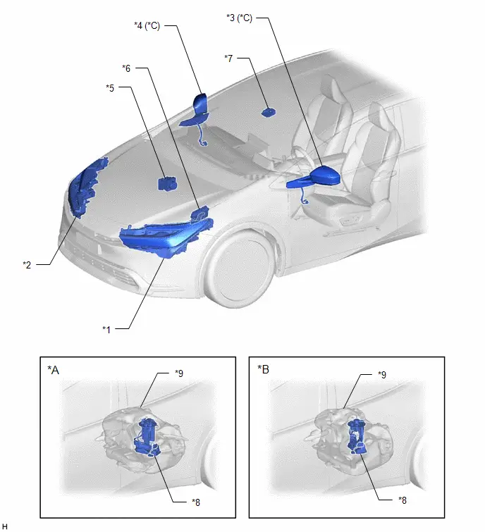
| *A | for 2ZR-FXE | *B | for M20A-FXS |
| *C | w/ Side turn signal light assembly | - | - |
| *1 | HEADLIGHT ASSEMBLY LH | *2 | HEADLIGHT ASSEMBLY RH |
| *3 | OUTER REAR VIEW MIRROR ASSEMBLY LH - SIDE TURN SIGNAL LIGHT ASSEMBLY LH | *4 | OUTER REAR VIEW MIRROR ASSEMBLY RH - SIDE TURN SIGNAL LIGHT ASSEMBLY RH |
| *5 | BRAKE ACTUATOR ASSEMBLY - NO. 2 SKID CONTROL ECU | *6 | ECM |
| *7 | FORWARD RECOGNITION CAMERA | *8 | FUEL SUCTION TUBE WITH PUMP AND GAUGE ASSEMBLY - FUEL SENDER GAUGE ASSEMBLY |
| *9 | FUEL TANK SUB-ASSEMBLY | - | - |
ILLUSTRATION
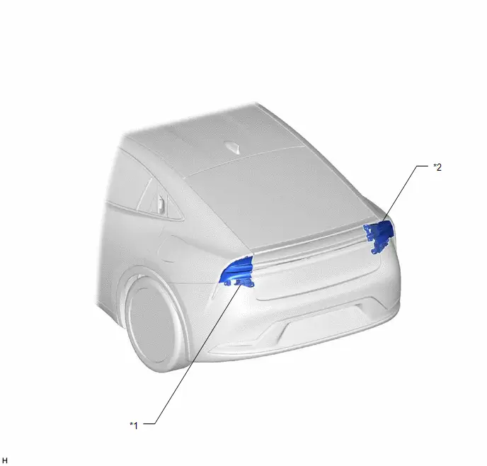
| *1 | REAR COMBINATION LIGHT ASSEMBLY LH | *2 | REAR COMBINATION LIGHT ASSEMBLY RH |
ILLUSTRATION
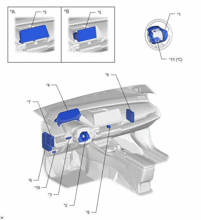
| *A | for 12.3 Inch Display Model | *B | for 8 Inch Display Model |
| *C | w/ Front Cross Traffic Alert | - | - |
| *1 | STEERING PAD SWITCH ASSEMBLY | *2 | SPIRAL CABLE SUB-ASSEMBLY |
| *3 | TRIP SWITCH - ODO/TRIP SWITCH - LIGHT CONTROL RHEOSTAT UP SWITCH - LIGHT CONTROL RHEOSTAT DOWN SWITCH | *4 | COMBINATION METER ASSEMBLY - MULTI-INFORMATION DISPLAY |
| *5 | RADIO AND DISPLAY RECEIVER ASSEMBLY | *6 | POWER DISTRIBUTION BOX ASSEMBLY - ECU-DCC NO. 2 FUSE - METER-IGR FUSE - HAZ FUSE |
| *7 | HYBRID Toyota Prius Vehicle CONTROL ECU | *8 | HAZARD WARNING SIGNAL SWITCH ASSEMBLY |
| *9 | CERTIFICATION ECU (SMART KEY ECU ASSEMBLY) | *10 | DLC3 |
| *11 | MULTIPLEX NETWORK STEERING ECU - STEERING VIBRATION ECU | - | - |
ILLUSTRATION
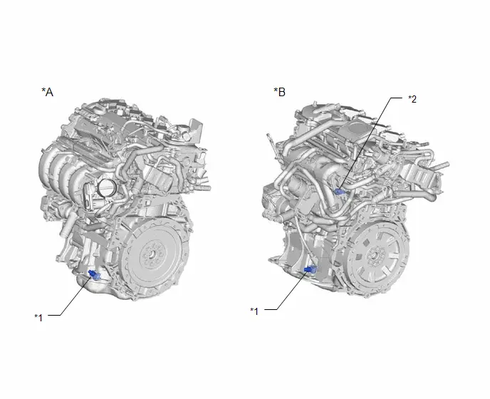
| *A | for M20A-FXS | *B | for 2ZR-FXE |
| *1 | ENGINE OIL LEVEL SENSOR | *2 | ENGINE OIL PRESSURE SWITCH ASSEMBLY |
System Diagram
SYSTEM DIAGRAM
HINT:
Refer to System Diagram of CAN Communication System.
for HEV Model: Click here

for PHEV Model: Click here

How To Proceed With Troubleshooting
CAUTION / NOTICE / HINT
HINT:
- Use the following procedure to troubleshoot the meter / gauge system.
- *: Use the GTS.
PROCEDURE
| 1. | Toyota Prius Vehicle BROUGHT TO WORKSHOP |
|

| 2. | CUSTOMER PROBLEM ANALYSIS |
HINT:
- In troubleshooting, confirm that the problem symptoms have been accurately identified. Preconceptions should be discarded in order to make an accurate judgment. To clearly understand what the problem symptoms are, it is extremely important to ask the customer about the problem and the conditions at the time the malfunction occurred.
- Gather as much information as possible for reference. Past problems that seem unrelated may also help in some cases.
-
The following 5 items are important points for problem analysis:
What
Toyota Prius Vehicle model, system name
When
Date, time, occurrence frequency
Where
Road conditions
Under what conditions?
Driving conditions, weather conditions
How did it happen?
Problem symptoms
|

| 3. | INSPECT AUXILIARY BATTERY VOLTAGE |
(a) Measure the auxiliary battery voltage.
Standard Voltage:
11 to 14 V (Ignition switch off)
If the voltage is below 11 V, recharge or replace the auxiliary battery before proceeding to the next step.
(b) Check the fuses and relays.
(c) Check the connector connections and terminals to make sure that there are no abnormalities such as loose connections, deformation, etc.
|

| 4. | CHECK CAN COMMUNICATION SYSTEM* |
(a) Using the GTS, check for CAN communication system DTCs.
for HEV Model: Click here

for PHEV Model: Click here

| Result | Proceed to |
|---|---|
| CAN DTCs are not output | A |
| CAN DTCs are output | B |
| B |

| GO TO CAN COMMUNICATION SYSTEM for HEV Model: Click here
for PHEV Model: Click here
|


|

| 5. | CHECK FOR DTC* (METER / GAUGE SYSTEM) |
(a) Check for DTCs.
Body Electrical > Combination Meter > Trouble Codes| Result | Proceed to |
|---|---|
| DTCs are not output | A |
| DTCs are output | B |
| B |

| GO TO DIAGNOSTIC TROUBLE CODE CHART |
|

| 6. | CHECK Toyota Prius Vehicle CONTROL HISTORY (RoB)* |
(a) Using the GTS, check for Vehicle Control History (RoB).
Body Electrical > Combination Meter > Utility| Tester Display |
|---|
| Toyota Prius Vehicle Control History (RoB) |
(b) Make a note of the output Vehicle Control History (RoB).
| Result | Proceed to |
|---|---|
| Toyota Prius Vehicle Control History (RoB) is not output | A |
| Vehicle Control History (RoB) is output | B |
| B |

| GO TO Toyota Prius Vehicle CONTROL HISTORY (RoB) |
|

| 7. | PROBLEM SYMPTOM CONFIRMATION |
|

| 8. | SYMPTOM SIMULATION |
|

| 9. | PROBLEM SYMPTOMS TABLE |
(a) Refer to Problem Symptoms Table.
Click here

NOTICE:
The problem symptoms table of the meter/gauge system is written based on the assumption that all related systems and ECUs of each function are operating correctly. Therefore, confirm that all related systems and ECUs are functioning correctly before using the problem symptoms table.
| Result | Proceed to |
|---|---|
| Fault is not listed in Problem Symptoms Table | A |
| Fault is listed in Problem Symptoms Table | B |
| B |

| GO TO PROBLEM SYMPTOMS TABLE |
|

| 10. | OVERALL ANALYSIS AND TROUBLESHOOTING* |
(a) Terminals of ECU.
Click here

(b) Data List / Active Test.
Click here

(c) Operation Check.
Click here

|

| 11. | CIRCUIT INSPECTION |
|

| 12. | ADJUST, REPAIR OR REPLACE |
|

| 13. | CONFIRMATION TEST |
| NEXT |

| END |
Operation Check
OPERATION CHECK
CHECK WARNING AND INDICATOR LIGHT ILLUMINATION
(a) Initial Check
(1) Turn the ignition switch off.
(2) Turn the ignition switch to ON (IG) or ON (READY).
(3) Check the operation of the following warning and indicator lights.
- MIL (Check engine warning light)
- Brake warning light/red (malfunction)
- Brake warning light/yellow (minor malfunction)
- ABS warning light
- Brake hold operated indicator light
- Brake hold standby indicator light
- Slip indicator light
- VSC OFF indicator light
- EPS warning light
-
PKSB OFF indicator light
(w/ Parking Support Brake System)
- PCS warning light
- Driving assist information indicator light
- SRS warning light
OK:
| Toyota Prius Vehicle Condition | Warning/Indicator Lights Condition |
|---|---|
| *: The amount of seconds until turning off differs depending on each indicator or warning light. | |
| Ignition switch off → ignition switch ON (IG) → ignition switch ON (READY) | Illuminates and turns off in either of the following patterns depending on the specification:
|
| Ignition switch off → ignition switch ON (READY) | Illuminates when the ignition switch is turned to ON (READY), and turns off after a certain amount of seconds has elapsed* |
CHECK SPEEDOMETER
NOTICE:
- If the tire size or tire inflation pressure is not within the specified range, or the tires are excessively worn, the speedometer indication error will increase. Therefore, make sure to perform this inspection after checking that the tire size, tire inflation pressure and tire wear are in the specified range.
- When the electronically controlled brake system is malfunctioning, an accurate Toyota Prius vehicle speed signal may not be able to be obtained. Therefore, make sure to confirm that the electronically controlled brake system is not malfunctioning before performing this procedure.
HINT:
The indicated value of the speedometer has an allowable range. Therefore, even when the combination meter assembly is not malfunctioning, the actual Toyota Prius vehicle speed and the indicated value speed may not match.
(a) Read the vehicle speed of the Data List item of the electronically controlled brake system and compare the indicated values of the speedometer with the following table.
for Speedometer Unit km/h Type (except 2ZR-FXE)| Data List: Toyota Prius vehicle speed value (km/h) | Acceptable Range (km/h) |
|---|---|
| 20 | 20.0 to 22.0 |
| 40 | 40.0 to 42.0 |
| 60 | 61.0 to 63.0 |
| 80 | 81.0 to 83.0 |
| 100 | 102.0 to 104.0 |
| 120 | 122.0 to 124.0 |
| 140 | 143.0 to 145.0 |
| 160 | 163.0 to 165.0 |
| 180 | 184.0 to 186.0 |
| 200 | 204.0 to 206.0 |
| 220 | 222.6 to 227.6 |
| 240 | 243.0 to 248.0 |
| 260 | 263.5 to 268.5 |
| Data List: Toyota Prius vehicle speed value (mph) | Acceptable Range (mph) |
|---|---|
| 20 | 20.0 to 22.0 |
| 40 | 40.0 to 42.0 |
| 60 | 61.0 to 63.0 |
| 80 | 81.0 to 83.0 |
| 100 | 102.0 to 104.0 |
| 120 | 122.0 to 124.0 |
| 140 | 143.0 to 145.0 |
| 160 | 163.0 to 165.0 |
| 180 | 184.0 to 186.0 |
| Data List: Toyota Prius vehicle speed value (km/h) | Acceptable Range (km/h) |
|---|---|
| 20 | 21.0 to 23.0 |
| 40 | 42.0 to 44.0 |
| 60 | 63.0 to 65.0 |
| 80 | 84.0 to 86.0 |
| 100 | 104.0 to 106.0 |
| 120 | 125.0 to 127.0 |
| 140 | 146.0 to 148.0 |
| 160 | 167.0 to 169.0 |
| 180 | 187.0 to 189.0 |
| 200 | 208.0 to 210.0 |
| 220 | 229.0 to 236.0 |
| 240 | 249.0 to 257.0 |
| 260 | 270.0 to 278.0 |
| Data List: Toyota Prius vehicle speed value (mph) | Acceptable Range (mph) |
|---|---|
| 20 | 21.0 to 23.0 |
| 40 | 42.0 to 44.0 |
| 60 | 63.0 to 65.0 |
| 80 | 83.0 to 85.0 |
| 100 | 104.0 to 106.0 |
| 120 | 125.0 to 127.0 |
| 140 | 146.0 to 148.0 |
| 160 | 166.0 to 168.0 |
| 180 | 187.0 to 189.0 |
OK:
Speedometer reading is within the acceptable range at each Toyota Prius vehicle speed.
Customize Parameters
CUSTOMIZE PARAMETERS
NOTICE:
- When the customer requests a change in a function, first make sure that the function can be customized.
- Be sure to make a note of the current settings before customizing.
- When troubleshooting a function, first make sure that the function is set to the default setting.
CUSTOMIZE METER / GAUGE SYSTEM
(a) Customizing with the GTS
(1) Select the setting by referring to the table below.
HINT:
Depending on the specifications of the Toyota Prius vehicle, some items may not be displayed.
Warning| Tester Display | Description | Default | Setting | ECU |
|---|---|---|---|---|
| Lane Change Flashing Times Adjust | Function to change the lane change flashing times. | 3 | $00:OFF,$01:3,$02:4,$03:5,$04:6,$05:7 | Combination meter assembly |
| Flasher Sound Volume Adjust | Function to change the turn signal flasher buzzer sound volume | Medium | $02:Large,$00:Medium,$01:Small | Combination meter assembly |
| Proposal Services Function | Function to change the suggestion function display setting | ON | $00:OFF,$01:Parked,$03:ON | Main body ECU (Multiplex network body ECU) |
| Reverse Buzzer Setting | Function to change the reverse buzzer setting | Mute | $00:Mute,$01:Continual | Combination meter assembly |
| Tester Display | Description | Default | Setting | ECU |
|---|---|---|---|---|
| ODO Display Time After IG OFF Adjust | Function to change the trip result display time after the ignition switch is turned off | 30s | $00:30s,$01:60s,$02:600s,$03:OFF | Combination meter assembly |
(b) Customizing with the multi-display
(1) Enter the following menus: MENU / Setup / Toyota Prius Vehicle / Vehicle customization.
(2) Select the setting by referring to the table below.
| Display | Default | Content | Setting | Relevant ECU |
|---|---|---|---|---|
| Suggestion Function | On | Function to change the suggestion function display setting | On/On (when the Toyota Prius vehicle is stopped)/Off | Main body ECU (Multiplex network body ECU) |
(c) Customizing with the multi-information display
(1) Select the settings tab on the multi-information display.
(2) Select the setting by referring to the table below.
NOTICE:
- When the cable is disconnected from the negative (-) auxiliary battery terminal, some of the settings will be reset. Therefore, it is necessary to make a note of each set value before disconnecting the cable.
- As some values cannot be selected when the Toyota Prius vehicle is being driven, perform the procedure with the vehicle stopped.
HINT:
Depending on the specifications of the vehicle, some items may not be displayed.
Lane Departure Alert System| Display | Description | Setting | ECU |
|---|---|---|---|
| Lane Departure Alert System | Lane departure alert system setting | ON/OFF | Forward recognition camera |
| Alert Options | Lane departure alert method setting | Steering vibration/buzzer | |
| Alert Timing | Lane departure alert timing level setting | 1/2 |
| Display | Description | Setting | ECU |
|---|---|---|---|
| - | Blind spot monitor system setting | ON/OFF | Blind spot monitor sensor LH (B) |
| Support timing | Change Support Timing | 1/2/3 | |
| Brightness | Outer rear view mirror indicator brightness level setting | 1/2 |
| Display | Description | Setting | ECU |
|---|---|---|---|
| Warning timing | Change Warning Timing | 1/2/3 | Forward recognition camera |
| PCS | Pre-collision system setting | ON/OFF |
| Display | Description | Setting | ECU |
|---|---|---|---|
| - | PDA system setting | ON/OFF | Forward recognition camera |
| Sensitivity | Change Sensitivity | 1/2/3 | |
| SA | System ON/OFF | ON/OFF | |
| DA | System ON/OFF | ON/OFF | |
| OAA | System ON/OFF | ON/OFF |
| Display | Description | Setting | ECU |
|---|---|---|---|
| - | TOYOTA parking assist-sensor system setting | ON/OFF | Clearance warning ECU assembly |
| Parking Assist System Volume | Clearance warning buzzer volume level setting | 3 levels |
| Display | Description | Setting | ECU |
|---|---|---|---|
| - | RCTA function setting | ON/OFF | Blind spot monitor sensor LH (B) |
| Parking Assist System Volume | RCTA buzzer (blind spot monitor buzzer) volume setting | 1/2/3 |
| Display | Description | Setting | ECU |
|---|---|---|---|
| - | RCD function setting | ON/OFF | Rear Television Camera Assembly |
| Display | Description | Setting | ECU |
|---|---|---|---|
| - | PKSB function setting | ON/OFF | Clearance warning ECU assembly |
| Display | Description | Setting | ECU |
|---|---|---|---|
| - | Safe Exit Assist system setting | ON/OFF | Blind spot monitor sensor LH (B) |
| Sensitivity | Change Sensitivity | 1/2/3 | |
| Mirror indicate | Door mirror indicator setting | ON/OFF |
| Display | Description | Setting | ECU | |
|---|---|---|---|---|
| - | Road sign assist system setting | ON/OFF | Forward recognition camera | |
| Notification Method | Above Speed Limit | Excess speed notification method setting | No Notification/Only Visual/Visual & Audio | |
| Others | Others traffic sign notification method setting | No Notification/Only Visual/Visual & Audio | ||
| Notification Level | Excess speed notification level setting | 10 km/h (5 MPH), 5 km/h (3 MPH), 2 km/h (1 MPH) | ||
| Display | Description | Setting | ECU |
|---|---|---|---|
| Acceleration Setting | Acceleration Setting Low/Mid/High | 1/2/3 | ECM |
| Speed Setting (Push) | Speed Setting (Push) /-1, /-5, /-10 | /-1, /-5, /-10 | |
| Speed setting (Hold) | Speed Setting (Hold) /-1, /-5, /-10 | /-1, /-5, /-10 | |
| Guide message | System ON/OFF | ON/OFF | |
| Curve Speed Reduction | Curve Speed Reduction System OFF/Low/Mid/High | 1/2/3 |
| Display | Description | Setting | ECU | |
|---|---|---|---|---|
| Charging Settings | Charging Schedule | Setting the timer charging |
| Electric Toyota Prius vehicle charger assembly |
| Charging Current | Changing the upper limit of the charging current | MAX/16A/8A | ||
| Connector Lock | Changing the charging connector lock settings | Auto Lock/Auto Lock & Unlock/OFF | ||
| Battery Cooler | Setting "HV Supply Battery Cooler" on/off. | ON/OFF | Battery ECU assembly | |
| Battery Heater | Setting "HV Supply Battery Heater" on/off. | ON/OFF | ||
| Electric Supply | Setting the power supply method | Electric/Hybrid | Battery ECU assembly | |
| Driver Break Suggestion | Driver Break Suggestion ON/OFF | ON/OFF | Combination meter assembly | |
| LCA | LCA ON/OFF | ON/OFF | Forward recognition camera | |
| FCTA | FCTA | FCTA setting | ON/OFF | Forward recognition camera |
| Timing | timing setting | 3 levels | ||
| TPWS setting | Tire Set Switching | Register replaced valve / ID | - | Tire Pressure Warning ECU and Receiver |
| Tire Rotation | Reset tire location | - | ||
| Tire Pressure Setting | Set tire warning pressure | - | ||
| Pressure unit setting | Change display units | - | ||
| Driver Monitor Settings | Driver Monitor Alert | Alert notification settings | ON/OFF | Driver Monitor ECU Assembly |
| Drowsiness Alert | Notification settings for drowsiness alert notifications | ON/OFF | ||
| Regenerative Brake | Deceleration | Deceleration settings | 1/2/3 | Hybrid Toyota Prius Vehicle Control ECU |
| Deceleration Memory | Deceleration memory settings | ON/OFF | ||
| PBD | System Settings | Hands free power back door function setting | ON/OFF | Multiplex network door ECU |
| Opening Adjustment | Back door opening stop position setting when operated by power back door system | 5 levels | ||
| Volume | Power back door buzzer volume level setting | 3 levels | ||
| Scheduled Maintenance | Scheduled maintenance data reset | Yes/No | ECM | |
| Oil Maintenance | Engine oil maintenance required reminder data reset | Yes/No | ECM | |
| Rear Seat Reminder | Rear seat reminder function setting | ON/OFF | Main body ECU (Multiplex network body ECU) | |
| My settings | setting | Change Driver and Settings | - | Main body ECU (Multiplex network body ECU) |
| function | Setting of my settings function | ON/OFF | ||
| Display | Description | Setting | ECU | ||
|---|---|---|---|---|---|
| Language | Display language setting | * | Related ECUs | ||
| Units | Display units setting | * | |||
| Meter Type | Meter Type setting | ON/OFF | Combination meter assembly | ||
| Eco driving indicator light | Eco driving indicator light display setting | ON/OFF | |||
| EV Drive Information | EV drive information setting | EV Energy remaining/EV Distance remaining | |||
| Eco-friendly driving information tab | Hybrid System | Eco Guidance | Display setting in eco-friendly driving information tab | ON/OFF | |
| Fuel Economy | Displayed fuel economy display item setting | Trip Average/Total Average/Tank Average | |||
| Power Consumption | Calculated value setting for electricity consumption information | Trip Average/Total Average | |||
| Audio tab | Audio tab display setting | ON/OFF | |||
| Drive Information | Display Contents | AWD | AWD system ON/OFF | ON/OFF | |
| Drive Info Type | Displayed drive information display item setting | Trip/Total | |||
| Drive Info Items | Displayed drive information display item setting | Average Speed/Distance/Total Time | |||
| Trip Summary | Current trip result display setting | Drive Info/Charging Schedule | |||
| Pop-Up Display | TbT Navigation | Interrupt display setting | ON/OFF | ||
| Telephone | Interrupt display setting | ON/OFF | |||
| Audio Operation | Interrupt display setting | ON/OFF | |||
| Volume Operation | Interrupt display setting | ON/OFF | |||
| Voice Control | Interrupt display setting | ON/OFF | |||
| Brightness | Interrupt display setting | ON/OFF | |||
| Calendar | Date setting | - | |||
| Default Settings | Reset the combination meter settings to the default setting | Yes/No | Related ECUs | ||
- *: Varies according to the Toyota Prius vehicle specification.
Initialization
INITIALIZATION
NOTICE:
Perform this procedure with the vehicle stopped.
OIL MAINTENANCE REQUIRED REMINDER RESET PROCEDURE
(a) Enter the following menus:
- Settings (icon) / Vehicle customize / Utility / Oil Maintenance
(b) Perform initialization according to the multi-information display.
NOTICE:
Perform this procedure with the Toyota Prius vehicle stopped.
SCHEDULED MAINTENANCE REQUIRED REMINDER RESET PROCEDURE
(a) Enter the following menus:
- Settings (icon) / Vehicle customize / Utility / Scheduled Maintenance
(b) Perform initialization according to the multi-information display.
Utility
UTILITY
INITIALIZATION OF DRIVABLE DISTANCE
HINT:
The learned value for calculating the drivable distance can be reset.
(a) Using the GTS, enter the following menu.
Body Electrical > Combination Meter > Utility| Tester Display |
|---|
| Cruising Range Reset |
(b) Perform the procedure displayed.
Terminals Of Ecu
TERMINALS OF ECU
COMBINATION METER ASSEMBLY
(a) Measure the voltage and resistance and check for pulses according to the value(s) in the table below.
| Terminal No. (Symbol) | Terminal Description | Condition | Specified Condition |
|---|---|---|---|
| K18-1 (EP) - Body ground | Ground | Always | Below 1 Ω |
| K18-2 (ES) - Body ground | Ground | Always | Below 1 Ω |
| K18-5 (B) - Body ground | Power source for auxiliary battery | Ignition switch off | 11 to 14 V |
| K18-6 (IG ) - Body ground | Power source for IG relay | IG OFF → IG ON | Below 1 V → 11 to 14 V |
| K18-8 ( S) - Body ground | Toyota Prius Vehicle speed output signal | Ignition switch ON, wheel being rotated | Pulse generation (See waveform 1) |
| K18-9 (OILW) - Body ground | Engine oil level sensor signal | Ignition switch ON, engine oil level not low → low | Below 1 V → 11 to 14 V |
| K18-12 (HZSW) - Body ground | Hazard warning signal switch signal | Hazard warning signal switch off → on | 11 to 14 V → Below 1 V |
| K18-25 (SI) - Body ground | Toyota Prius Vehicle speed input signal | Ignition switch ON, wheel being rotated | Pulse generation (See waveform 1) |
| K18-28 (LST1) - Body ground | Fuel lid status signal | Ignition switch OFF | 11 to 14 V |
| The following message (interrupt display) being displayed on the multi-information display:
| Pulse generation (See waveform 4) | ||
| The following message (interrupt display) being displayed on the multi-information display:
| Pulse generation (See waveform 5) | ||
| K18-29 (BKL) - Body ground | Driver seat belt buckle switch signal | Ignition switch ON, driver seat belt unfastened → fastened | Below 1 V → 11 to 14 V |
| K18-32 (CXPI) - Body ground*1 | CXPI communication signal | - | - |
| K19-2 (B) - Body ground | Power source for auxiliary battery | Ignition switch off | 11 to 14 V |
| K19-5 (LL) - Body ground | Front/side turn signal flasher signal (LH side) | Turn indicator light (LH) blinking | 11 to 14 V ←→ Below 1 V |
| Turn indicator light (LH) off | Below 1 V | ||
| K19-6 (LR) - Body ground | Front/side turn signal flasher signal (RH side) | Turn indicator light (RH) blinking | 11 to 14 V ←→ Below 1 V |
| Turn indicator light (RH) off | Below 1 V | ||
| K19-7 (FR) - K19-25 (FE&B) | Fuel level signal | Ignition switch ON, fuel receiver gauge indicates F → E (fuel level warning light on) | Pulse generation (See waveform 2) |
| K19-12 (MSTI) - Body ground | Steering pad switch without touch detection function signal | Ignition switch ON, up, down, left and right switches on steering pad switch not pushed | 4.8 to 5.2 V |
| K19-13 (ODO) - Body ground | ODO/TRIP switch signal | Ignition switch ON, ODO/TRIP switch not pushed | 4.8 to 5.2 V |
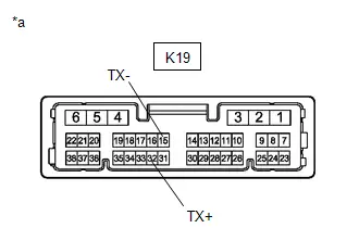
| K19-14 (CANL) | CAN communication signal | - | - |
| K19-15 (TX-) | Local bus communication signal | - | - |
| K19-20 (S) - Body ground*2 | Engine oil pressure signal | Engine started → not started | 11 to 14 V → Below 1 V |
| K19-21 (TRNR) - Body ground | Rear turn signal flasher signal (RH side) | Turn indicator light (RH) blinking | 11 to 14 V ←→ Below 1 V |
| Turn indicator light (RH) off | Below 1 V | ||
| K19-22 (TRNL) - Body ground | Rear turn signal flasher signal (LH side) | Turn indicator light (LH) blinking | 11 to 14 V ←→ Below 1 V |
| Turn indicator light (LH) off | Below 1 V | ||
| K19-23 (FV) - Body ground | Power source for fuel sender gauge | Ignition switch ON | Pulse generation (See waveform 3) |
| K19-25 (FE&B) - Body ground | Ground for fuel sender gauge | Always | Below 1 Ω |
| K19-26 (SW3) - Body ground | Ground for trip switch | Always | Below 1 Ω |
| K19-28 (TR) - Body ground | Light control rheostat switch signal | Ignition switch ON, light control rheostat up and down switches not pushed | 4.8 to 5.2 V |
| K19-29 (MSM ) - Body ground | Steering pad switch without touch detection function signal | Ignition switch ON, OK and back switches on steering pad switch not pushed | 4.8 to 5.2 V |
| K19-31 (CANH) | CAN communication signal | - | - |
| K19-32 (TX ) | Local bus communication signal | - | - |
| K19-36 (WLVL) - Body ground*3 | Washer fluid level signal | Ignition switch ON, washer fluid level not low → low | 11 to 14 V → Below 1 V |
- *1: w/ Multiplex Network Steering ECU
- *2: for 2ZR-FXE
- *3: w/ Washer Fluid Level Warning
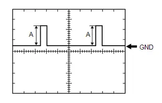
- Waveform 1:
Item
Condition
Tester connection
- K18-8 ( S) - Body ground
- K18-25 (SI) - Body ground
Tool setting
5 V/DIV., 20 ms./DIV.
Condition
Ignition switch ON, wheel being rotated
HINT:
When the system is functioning normally, one wheel revolution generates 4 pulses. As the Toyota Prius vehicle speed increases, the width indicated by (A) in the illustration narrows.
- Waveform 2:
Item
Condition
Tester connection
K19-7 (FR) - K19-25 (FE&B)
Tool setting
2.5 V/DIV., 20 ms./DIV.
Condition
Ignition switch ON, fuel receiver gauge indicates F → E (fuel level warning light on)
HINT:
The magnitude of the voltage (A) changes as shown in the following tables.
except 4WD Model:
for 4WD Model:Terminal No. (Symbol)
Condition
Specified Condition
K19-7 (FR) - K19-25 (FE&B)
Ignition switch ON, fuel receiver gauge indicates F
3.9 to 4.6 V
Ignition switch ON, fuel receiver gauge indicates below 1/2
2.2 V
Ignition switch ON, fuel receiver gauge indicates E
(fuel level warning light on)
0.3 to 0.9 V
Terminal No. (Symbol)
Condition
Specified Condition
K19-7 (FR) - K19-25 (FE&B)
Ignition switch ON, fuel receiver gauge indicates F
3.9 to 4.6 V
Ignition switch ON, fuel receiver gauge indicates below 1/2
2.1 V
Ignition switch ON, fuel receiver gauge indicates E
(fuel level warning light on)
0.3 to 0.9 V
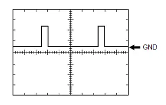
- Waveform 3:
Item
Condition
Tester connection
K19-23 (FV) - Body ground
Tool setting
2.5 V/DIV., 20 ms./DIV.
Condition
Ignition switch ON
Specified Condition
4.5 to 5.5 V
- Waveform 4:
Item
Condition
Tester connection
K18-28 (LST1) - Body ground
Tool setting
5 V/DIV., 20 ms./DIV.
Condition
The following message (interrupt display) being displayed on the multi-information display:
- "Ready to Refuel"

- Waveform 5:
Item
Condition
Tester connection
K18-28 (LST1) - Body ground
Tool setting
5 V/DIV., 20 ms./DIV.
Condition
The following message (interrupt display) being displayed on the multi-information display:
- "Close Fuel Lid"

HINT:
This waveform is output when the fuel lid opener switch is operated if the fuel lid is open and any of the following conditions are met:
- The Toyota Prius vehicle has been driven for 1 km (0.6 mile) or more at a speed of 50 km/h (31 mph) or more.
- 30 minutes or more have elapsed since the fuel lid opener switch was operated.
Data List / Active Test
DATA LIST / ACTIVE TEST
DATA LIST
NOTICE:
In the table below, the values listed under "Normal Condition" are reference values. Do not depend solely on these reference values when deciding whether a part is faulty or not.
HINT:
Using the GTS to read the Data List allows the values or states of switches, sensors, actuators and other items to be read without removing any parts. This non-intrusive inspection can be very useful because intermittent conditions or signals may be discovered before parts or wiring is disturbed. Reading the Data List information early in troubleshooting is one way to save diagnostic time.
(a) Read the Data List according to the display on the GTS.
(1) Combination Meter
HINT:
Depending on the specifications of the Toyota Prius vehicle, some items may not be displayed.
Body Electrical > Combination Meter > Data List| Tester Display | Measurement Item | Range | Normal Condition | Diagnostic Note |
|---|---|---|---|---|
| Total Distance Traveled | Total distance traveled | Min.: 0, Max.: 16777215 | - | - |
| Total Distance Traveled - Unit | Total distance traveled unit | km or mile | - | - |
| ODO/TRIP Change Switch | ODO/TRIP switch operation | OFF or ON | OFF: Switch released ON: Switch pushed | - |
| Light Control Switch (UP) | Light control rheostat up switch operation | OFF or ON | OFF: Switch released ON: Switch pushed | - |
| Light Control Switch (DOWN) | Light control rheostat down switch operation | OFF or ON | OFF: Switch released ON: Switch pushed | - |
| Multi Switch (Up) | Up switch on steering pad switch operation | OFF or ON | OFF: Switch released ON: Switch pushed | - |
| Multi Switch (Down) | Down switch on steering pad switch operation | OFF or ON | OFF: Switch released ON: Switch pushed | - |
| Multi Switch (Left) | Left switch on steering pad switch operation | OFF or ON | OFF: Switch released ON: Switch pushed | - |
| Multi Switch (Right) | Right switch on steering pad switch operation | OFF or ON | OFF: Switch released ON: Switch pushed | - |
| Multi Switch (Enter) | OK switch on steering pad switch operation | OFF or ON | OFF: Switch released ON: Switch pushed | - |
| Multi Switch (Back) | Back switch on steering pad switch operation | OFF or ON | OFF: Switch released ON: Switch pushed | - |
| B Voltage | Auxiliary battery voltage (Combination meter assembly input) | Min.: 0.0 V, Max.: 25.4 V or Unset | 11 to 14 V | - |
| Fuel Input | Fuel level input | Min.: 0.00 L, Max.: 655.34 L or Unset | for HEV Model (except 4WD Model)
for HEV Model (for 4WD Model)
for PHEV Model
| The detected value of the fuel sender gauge assembly is displayed. |
| Toyota Prius Vehicle Speed Meter | Vehicle speed input | Min.: 0 km/h (0 mph), Max.: 254 km/h (158 mph) or Unset | Almost the same as actual speedometer | The value displayed on the speedometer may deviate.* |
| Engine RPM | Engine speed input | Min.: 0 rpm, Max.: 12700 rpm or Unset | Almost the same as actual engine RPM | - |
| Washer Level Warning Switch | Washer fluid level warning switch input | OFF or ON | OFF: Washer fluid level not low ON: Washer fluid level low | - |
| Driver Buckle Switch | Seat belt buckle switch input (for Driver seat) | Fastened or Not Fastened | Fastened: Driver seat belt buckle switch fastened Not Fastened: Driver seat belt buckle switch unfastened | - |
| Hazard Flasher Switch | Hazard warning signal switch input | OFF or ON | OFF: Hazard warning signal switch off ON: Hazard warning signal switch on | - |
| Ambient Temperature (Celsius) | Outside temperature input (Celsius) | Min.: -40.0°C, Max.: 87.0°C or Unset | Almost the same as actual outside temperature | - |
| Ambient Temperature (Fahrenheit) | Outside temperature input (Fahrenheit) | Min.: -40°F, Max.: 214°F or Unset | Almost the same as actual outside temperature | - |
| Lighting System | Existence of headlight ECU | Without or With | Without: w/o Headlight ECU With: w/ Headlight ECU | - |
| Back Door System | Existence of power back door system | Without or With | Without: w/o Power Back Door System With: w/ Power Back Door System | - |
| Oil Pressure Switch | Engine oil pressure switch input | OFF or ON | OFF: Engine started ON: Engine not started | - |
| Oil Level Switch | Engine oil level sensor input | OFF or ON | OFF: Engine oil level not low ON: Engine oil level low | - |
| Coolant Temperature | Engine coolant temperature input | Min.: 0.0°C, Max.: 127.1°C or Unset | 75 to 100°C: After warming up engine | - |
| Integrated value for Maintenance | Maintenance required reminder value | Min.: 0 miles, Max.: 25401 miles or Unset | Driving distance after performing maintenance required reminder reset procedure displayed | - |
| TPMS System | Existence of tire pressure warning system | Without or With | Without: w/o Tire Pressure Warning System With: w/ Tire Pressure Warning System | - |
| VSC System | Existence of electronically controlled brake system | Without or With | Without: w/o Electronically Controlled Brake System With: w/ Electronically Controlled Brake System | - |
| LDA System | Existence of lane departure alert system | Without or With | Without: w/o Lane departure alert system Without: w/o Lane departure alert system | - |
| PCS System | Existence of pre-collision system | Without or With | Without: w/o Pre-collision System With: w/ Pre-collision System | - |
| ICS System | Existence of parking support brake system | Without or With | Without: w/o Parking Support Brake System With: w/ Parking Support Brake System | - |
| Radar Cruise System | Existence of dynamic radar cruise control system | Without or With | Without: w/o Dynamic Radar Cruise Control System With: w/ Dynamic Radar Cruise Control System | - |
| Intuitive P/A System | Existence of intuitive parking assist system | Without or With | Without: w/o Intuitive Parking Assist System With: w/ Intuitive Parking Assist System | - |
| Road Sign Assist System | Existence of road sign assist system | Without or With | Without: w/o Road Sign Assist System With: w/ Road Sign Assist System | - |
| HV/EV System Indicator | Hybrid system indicator value | Min.: -100%, Max.: 511% or Unset | Current hybrid system indicator status | If it is possible to customize the setting, the current setting is displayed. |
| ODO Display Time After IG OFF Adjust | Setting of trip result display time after the ignition switch is turned off | 30s, 60s, 600s or OFF | - | If it is possible to customize the setting, the current setting is displayed. |
| Tail Remind Buzzer Function | Condition of the tail remind buzzer | OFF or ON | Customized setting displayed | - |
| Lane Change Flashing Times Adjust | Setting of lane change flashing time adjustment | OFF, 3, 4, 5, 6 or 7 | Customized setting displayed | - |
| Flasher Sound Volume Adjust | Setting of flasher sound volume adjustment | Large, Medium or Small | - | If it is possible to customize the setting, the current setting is displayed. |
| Sub Fuel Sender | No. 2 fuel sender gauge assembly | Without or With | Without: w/o No. 2 Fuel Sender Gauge Assembly With: w/ No. 2 Fuel Sender Gauge Assembly | - |
| FCTA System | Existence of FCTA function | Without or With | Without: w/o FCTA function With: w/ FCTA function | - |
| Navigation System | Existence of navigation system | Without or With | Without: w/o Navigation System With: w/ Navigation System | - |
-
*: For the tolerance of each meter, refer to Operation Check.
Click here

(2) Main Body
Body Electrical > Main Body > Data List| Tester Display | Measurement Item | Range | Normal Condition | Diagnostic Note |
|---|---|---|---|---|
| Support Service Function | Setting of Suggestion Service | OFF, Parked or ON | - | If it is possible to customize the setting, the current setting is displayed. |
ACTIVE TEST
HINT:
Using the GTS to perform Active Tests allows relays, VSVs, actuators and other items to be operated without removing any parts. This non-intrusive functional inspection can be very useful because intermittent operation may be discovered before parts or wiring is disturbed. Performing Active Tests early in troubleshooting is one way to save diagnostic time. Data List information can be displayed while performing Active Tests.
(a) Perform the Active Test according the display on the GTS.
HINT:
Depending on the specifications of the Toyota Prius vehicle, some items may not be displayed.
Body Electrical > Combination Meter > Active Test| Tester Display | Measurement Item | Control Range | Diagnostic Note |
|---|---|---|---|
| Fuel Gauge Operation (Sender E) | Fuel receiver gauge (Fuel sender gauge lower limit) | ON | See [Display 1] |
| Fuel Gauge Operation (Empty) | Fuel receiver gauge (Fuel receiver gauge indicates E) | ON | See [Display 1] |
| Fuel Gauge Operation (Warning) | Fuel receiver gauge (Position at which fuel level warning light turns on/off) | ON | See [Display 1] |
| Fuel Gauge Operation (1/4) | Fuel receiver gauge (Fuel receiver gauge indicates 1/4) | ON | See [Display 1] |
| Fuel Gauge Operation (1/2) | Fuel receiver gauge (Fuel receiver gauge indicates 1/2) | ON | See [Display 1] |
| Fuel Gauge Operation (3/4) | Fuel receiver gauge (Fuel receiver gauge indicates 3/4) | ON | See [Display 1] |
| Fuel Gauge Operation (Full) | Fuel receiver gauge (Fuel receiver gauge indicates F) | ON | See [Display 1] |
| Fuel Gauge Operation (Sender F) | Fuel receiver gauge (Fuel sender gauge upper limit) | ON | See [Display 1] |
| SOC Gauge (MIN) | SOC gauge (SOC gauge indicates lower limit) | ON | - |
| SOC Gauge (1/4) | SOC gauge (SOC gauge indicates 1/4) | ON | - |
| SOC Gauge (1/2) | SOC gauge (SOC gauge indicates 1/2) | ON | - |
| SOC Gauge (3/4) | SOC gauge (SOC gauge indicates 3/4) | ON | - |
| SOC Gauge (MAX) | SOC gauge (SOC gauge indicates upper limit) | ON | - |
| Multi Display All (White) | Multi-information display (White color display) | ON | - |
| Multi Display Default Screen | Multi-information display (Default screen) | ON | - |
| High Beam Indicator | High beam indicator light | OFF or ON | - |
| Taillamp Indicator | Tail indicator light | OFF or ON | - |
| Rear Fog Lamp Indicator | Rear fog indicator light | OFF or ON | - |
| Automatic High Beam Indicator (Green) | Automatic high beam/adaptive high beam indicator light | OFF or ON | - |
| Left Turn Signal Indicator | Turn indicator light (LH side) | OFF or ON | - |
| Right Turn Signal Indicator | Turn indicator light (RH side) | OFF or ON | - |
| Driver Side Seat Belt Warning | Driver or front passenger seat belt warning light | OFF or ON | - |
| Airbag Warning | SRS warning light | OFF or ON | - |
| Coolant Hot Warning Lamp | Engine coolant temperature hot warning light | OFF or ON | - |
| Check Engine Warning | MIL (Check engine warning light) | OFF or ON | - |
| Brake Warning | Brake warning light / red (malfunction) | OFF or ON | - |
| Park Warning | Parking brake indicator light | OFF or ON | - |
| ABS Warning | ABS warning light | OFF or ON | - |
| ECB Warning | Brake warning light / yellow (minor malfunction) | OFF or ON | - |
| Slip Warning | Slip indicator light | OFF or ON | - |
| VSC OFF Indicator | VSC OFF indicator light | OFF or ON | - |
| Brake Hold Indicator | Brake hold standby indicator light | OFF or ON | - |
| Hold Indicator | Brake hold operated indicator light | OFF or ON | - |
| Tire Pressure Warning System Indicator | Tire pressure warning light | OFF or ON | - |
| EPS Warning | EPS warning light (Red) | OFF or ON | - |
| PPS Warning | EPS warning light (Amber) | OFF or ON | - |
| PCS OFF Warning | PCS warning light | OFF or ON | - |
| INTUITIVE P/A LCD OFF Indicator | Clearance sonar LCD OFF indicator light | OFF or ON | - |
| Ready Indicator | Ready indicator light | OFF or ON | - |
| Charge Warning (Red) | Charge warning light (Red) | OFF or ON | - |
| ADAS Integrated Warning | Driving assist information indicator light | OFF or ON | - |
| Plus Support Indicator | Plus Support indicator light | OFF or ON | - |
| Speed Signal Input (0) | Toyota Prius Vehicle speed test signal input | ON | When this Active Test is performed, an actual vehicle speed signal is sent via CAN communication to the combination meter assembly to operate the speedometer. The seat belt warning buzzer, etc. may operate when performing this Active Test. |
| Speed Signal Input (40) | Toyota Prius Vehicle speed test signal input | ON |
|
| Speed Signal Input (80) | Toyota Prius Vehicle speed test signal input | ON |
|
| Speed Signal Input (120) | Toyota Prius Vehicle speed test signal input | ON |
|
| Speed Signal Input (160) | Toyota Prius Vehicle speed test signal input | ON |
|
| Speed Signal Input (200) | Toyota Prius Vehicle speed test signal input | ON |
|
| Speed Signal Input (240) | Toyota Prius Vehicle speed test signal input | ON |
|
| Speed Signal Input (280) | Toyota Prius Vehicle speed test signal input | ON |
|
| Speed Signal Input (320) | Toyota Prius Vehicle speed test signal input | ON |
|
| Speed Signal Input (360) | Toyota Prius Vehicle speed test signal input | ON |
|
| Speed Signal Input (400) | Toyota Prius Vehicle speed test signal input | ON |
|
| ODO/TRIP Change Switch | Performs the same operation as pressing the ODO/TRIP switch | OFF or ON | - |
| Light Control Switch (UP) | Performs the same operation as pressing the light control rheostat up switch | OFF or ON | - |
| Light Control Switch (DOWN) | Performs the same operation as pressing the light control rheostat down switch | OFF or ON | - |
| Multi Switch (Up) | Performs the same operation as pressing the up switch on steering pad switch | OFF or ON | - |
| Multi Switch (Down) | Performs the same operation as pressing the down switch on steering pad switch | - | |
| Multi Switch (Left) | Performs the same operation as pressing the left switch on steering pad switch | OFF or ON | - |
| Multi Switch (Right) | Performs the same operation as pressing the right switch on steering pad switch | OFF or ON | - |
| Multi Switch (Enter) | Performs the same operation as pressing the OK switch on steering pad switch | OFF or ON | - |
| Multi Switch (Back) | Performs the same operation as pressing the back switch on steering pad switch | OFF or ON | - |
| Intuitive P/A Front Buzzer (Short) | Clearance warning buzzer
| ON | - |
| Intuitive P/A Front Buzzer (Middle) | Clearance warning buzzer
| ON | - |
| Intuitive P/A Front Buzzer (Far) | Clearance warning buzzer
| ON | - |
| Intuitive P/A Front Buzzer (Farthest) | Clearance warning buzzer
| ON | - |
| Intuitive P/A Rear Buzzer (Short) | Clearance warning buzzer
| ON | - |
| Intuitive P/A Rear Buzzer (Middle) | Clearance warning buzzer
| ON | - |
| Intuitive P/A Rear Buzzer (Far) | Clearance warning buzzer
| ON | - |
| Intuitive P/A Rear Buzzer (Farthest) | Clearance warning buzzer
| ON | - |
| Intuitive P/A Front/Rear Buzzer (Short) | Clearance warning buzzer
| ON | - |
| Intuitive P/A Front/Rear Buzzer (Middle) | Clearance warning buzzer
| ON | - |
| Intuitive P/A Front/Rear Buzzer (Far) | Clearance warning buzzer
| ON | - |
| Intuitive P/A Front/Rear Buzzer (Farthest) | Clearance warning buzzer
| ON | - |
-
*: For the tolerance of each meter, refer to Operation Check.
Click here

HINT:
[Display 1]: Fuel Gauge Operation-

Refer to the following table for the specified fuel receiver gauge position for each selected value:*a
Fuel Receiver Gauge
*b
Segments
Tester Display
Fuel Receiver Gauge Indication
Fuel Gauge Operation
(Sender E)
Not indicated
Fuel Gauge Operation
(Empty)
Not indicated
Fuel Gauge Operation
(Warning)
Approximately 1 is indicated
Fuel Gauge Operation
(1/4)
Approximately 2 is indicated
Fuel Gauge Operation
(1/2)
Approximately 3 is indicated
Fuel Gauge Operation
(3/4)
Approximately 4 is indicated
Fuel Gauge Operation
(Full)
Approximately 5 is indicated
Fuel Gauge Operation
(Sender F)
Approximately 5 is indicated
VEHICLE CONTROL HISTORY (RoB)
VEHICLE CONTROL HISTORY (RoB)
NOTICE:
When checking the vehicle control history (RoB), first store the output history and then check the history.
VEHICLE CONTROL HISTORY (RoB)
(a) Using the GTS, enter the following menu.
Body Electrical > Combination Meter > Utility| Tester Display |
|---|
| Toyota Prius Vehicle Control History (RoB) |
(b) Read the Vehicle Control History (RoB) according to the display on the GTS.
| Code | Tester Display | Description | Diagnostic Note |
|---|---|---|---|
| XF01B | ECU Security Key Not Registered | ECU security key has not been registered. | Refer to the ECU security key registration.
|

NOTICE:
By performing this procedure, all stored Toyota Prius Vehicle Control History (RoB) will be cleared.
DELETE VEHICLE CONTROL HISTORY (RoB)
(a) Using the GTS, enter the following menu.
Body Electrical > Combination Meter > Utility| Tester Display |
|---|
| Toyota Prius Vehicle Control History (RoB) |
(b) Clear the Vehicle Control History (RoB) according to the display on the GTS.
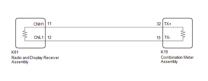
Lost Communication with EMV Missing Message (B132187)
DESCRIPTION
After the combination meter assembly has started, the combination meter assembly attempts to detect the radio and display receiver assembly by performing communication via local bus.
This DTC is stored when the radio and display receiver assembly has been detected but communication between the combination meter assembly and radio and display receiver assembly is interrupted.
| DTC No. | Detection Item | DTC Detection Condition | Trouble Area | DTC Output from | Priority |
|---|---|---|---|---|---|
| B132187 | Lost Communication with EMV Missing Message | Diagnosis Condition:
Malfunction Status:
Malfunction Time:
|
| Combination Meter | A |
WIRING DIAGRAM
CHECK POINT
- When DTC B132187 is output from the combination meter assembly, other ECUs on the same detection circuit may simultaneously output the same DTC depending on the malfunctioning area.
- Depending on the combination of DTCs simultaneously output by each ECU, the malfunctioning area can be narrowed down. Refer to the following table for DTC combinations output by each ECU.
| DTC Output Pattern | DTC Output Part Name (Display on GTS) | Malfunction Status/Suspected Area | |
|---|---|---|---|
| Combination Meter Assembly (Combination Meter) | Radio and Display Receiver Assembly (Navigation System) | ||
| 1 | B132187 | U11D087 |
|
| 2 | B132187 | Not output |
|
CAUTION / NOTICE / HINT
NOTICE:
- When replacing the combination meter assembly, always replace it with a new one. If a combination meter assembly which was installed to another Toyota Prius vehicle is used, the information stored in it will not match the information from the vehicle and a DTC may be stored.
-
When replacing the combination meter assembly, update the ECU security key.
Click here

-
After the ignition switch is turned off, there may be a waiting time before disconnecting the negative (-) auxiliary battery terminal.
Click here

-
If the power source circuit for any of the following ECUs is malfunctioning, DTCs may not be correctly output. Therefore, before performing troubleshooting using the following procedure, perform inspections related to the power source circuit of each ECU.
-
Radio and display receiver assembly
AUDIO AND VISUAL SYSTEM: Click here


-
Combination meter assembly
Click here

-
Radio and display receiver assembly
PROCEDURE
| 1. | CHECK FOR DTC |
(a) Check each system for DTCs.
Body Electrical > Combination Meter > Trouble Codes Body Electrical > Navigation System > Trouble Codes(b) Confirm the DTC combinations of the following table.
| DTC Output Pattern | DTC Output Part Name (Display on GTS) | |
|---|---|---|
| Combination Meter Assembly (Combination Meter) | Radio and Display Receiver Assembly (Navigation System) | |
| 1 | B132187 | U11D087 |
| 2 | B132187 | Not output |
| Result | Proceed to |
|---|---|
| DTC output pattern 1 | A |
| DTC output pattern 2 | B |
| B |

| GO TO STEP 3 |
|

| 2. | INSPECT EACH ECU (INTERNAL MALFUNCTION) |
Pre-procedure1
(a) Remove 1 of the following ECUs.
-
Radio and display receiver assembly
HINT:
Click here

-
Combination meter assembly
HINT:
Click here

Procedure1
(b) Measure the resistance of the removed ECU.
NOTICE:
- Refer to the following table for the specified conditions of each ECU.
- If the specified conditions are met, repeat the inspection procedure from step (a) for another ECU.
HINT:
If the results of an ECU are not as specified, it is suspected that the ECU is the cause of the DTC.
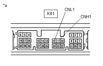
| (1) Inspect the radio and display receiver assembly. Standard Resistance:  Click Location & Routing(K81) Click Connector(K81) Click Location & Routing(K81) Click Connector(K81)
|
|
| (2) Inspect the combination meter assembly. Standard Resistance:  Click Location & Routing(K19) Click Connector(K19) Click Location & Routing(K19) Click Connector(K19)
Result:
|
|
Post-procedure1
(c) None
| A |

| REPAIR OR REPLACE HARNESS OR CONNECTOR |
| B |

| REPLACE RADIO AND DISPLAY RECEIVER ASSEMBLY |
| C |

| REPLACE COMBINATION METER ASSEMBLY |
| 3. | CLEAR DTC |
(a) Clear the DTCs.
Body Electrical > Combination Meter > Clear DTCs
|

| 4. | CHECK FOR DTC |
Pre-procedure1
(a) Disconnect the cable from the negative (-) auxiliary battery terminal.
HINT:
By disconnecting the cable from the negative (-) auxiliary battery terminal, the internally stored information related to local bus communication for the combination meter assembly is reset.
(b) Disconnect the K81 radio and display receiver assembly connector.
(c) Connect the cable to the negative (-) auxiliary battery terminal.
Pre-procedure2
(d) Turn the ignition switch to ON.
(e) Wait 30 seconds or more.
Procedure1
(f) Check for DTCs.
Body Electrical > Combination Meter > Trouble CodesHINT:
By resetting the internally stored information related to local bus communication, the detection conditions of DTC B132187 are not met as the combination meter assembly does not detect the radio and display receiver assembly. If the combination meter assembly is operating normally, DTC B132187 will not be stored.
| Result | Proceed to |
|---|---|
| B132187 is not output | A |
| B132187 is output | B |
Post-procedure1
(g) None
| A |

| REPLACE RADIO AND DISPLAY RECEIVER ASSEMBLY |
| B |

| REPLACE COMBINATION METER ASSEMBLY |
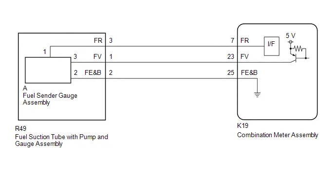
Fuel Sender Circuit Open (B150013)
DESCRIPTION
- The fuel sender gauge assembly is connected to the combination meter assembly via direct line. If there is an open or short in the direct line, the combination meter assembly stores DTC B150013.
| DTC No. | Detection Item | DTC Detection Condition | Trouble Area | DTC Output from | Priority |
|---|---|---|---|---|---|
| B150013 | Fuel Sender Circuit Open | Diagnosis Condition:
Malfunction Status:
Malfunction Time:
|
| Combination Meter | A |
WIRING DIAGRAM
CAUTION / NOTICE / HINT
NOTICE:
- When replacing the combination meter assembly, always replace it with a new one. If a combination meter assembly which was installed to another Toyota Prius vehicle is used, the information stored in it will not match the information from the vehicle and a DTC may be stored.
-
When replacing the combination meter assembly, update the ECU security key.
Click here

PROCEDURE
| 1. | READ VALUE USING GTS |
(a) Read the Data List according to the display on the GTS.
Body Electrical > Combination Meter > Data List| Tester Display | Measurement Item | Range | Normal Condition | Diagnostic Note |
|---|---|---|---|---|
| Fuel Input | Fuel level input | Min.: 0.00 L, Max.: 655.35 L or Unset | for HEV Model (except 4WD Model)
for HEV Model (for 4WD Model)
for PHEV Model
| The detected value of the fuel sender gauge assembly is displayed. |
| Tester Display |
|---|
| Fuel Input |
| Result | Proceed to |
|---|---|
| Fuel level data can be displayed on the GTS | A |
| Fuel level data cannot be displayed on the GTS | B |
| A |

| REPLACE COMBINATION METER ASSEMBLY |
|

| 2. | INSPECT FUEL SENDER GAUGE ASSEMBLY |
for 2ZR-FXE: Click here

for M20A-FXS (for HEV Model): Click here

for M20A-FXS (for PHEV Model): Click here

| NG |

| REPLACE FUEL SENDER GAUGE ASSEMBLY for 2ZR-FXE: Click here
for M20A-FXS (for HEV Model): Click here
for M20A-FXS (for PHEV Model): Click here
|


|

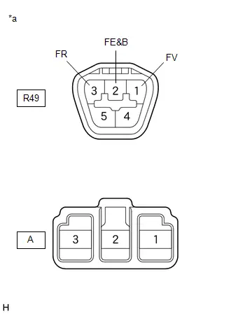
| 3. | INSPECT FUEL SUCTION TUBE WITH PUMP AND GAUGE ASSEMBLY |
| (a) Measure the resistance according to the value(s) in the table below. Standard Resistance:  Click Location & Routing(R49) Click Connector(R49) Click Location & Routing(R49) Click Connector(R49)
|
|
| NG |

| REPLACE FUEL SUCTION TUBE WITH PUMP AND GAUGE ASSEMBLY for 2ZR-FXE: Click here
for M20A-FXS (for HEV Model): Click here
for M20A-FXS (for PHEV Model): Click here
|


|

| 4. | CHECK HARNESS AND CONNECTOR (FUEL SUCTION TUBE WITH PUMP AND GAUGE ASSEMBLY - COMBINATION METER ASSEMBLY) |
Pre-procedure1
(a) Disconnect the K19 combination meter assembly connector.
Procedure1
(b) Measure the resistance according to the value(s) in the table below.
Standard Resistance:
 Click Location & Routing(R49,K19) Click Connector(R49) Click Connector(K19)
 | Tester Connection | Condition | Specified Condition | Result |
|---|---|---|---|
| R49-3 (FR) - K19-7 (FR) | Always | Below 1 Ω | Ω |
| R49-2 (FE&B) - K19-25 (FE&B) | Always | Below 1 Ω | Ω |
| R49-1 (FV) - K19-23 (FV) | Always | Below 1 Ω | Ω |
| R49-3 (FR) or K19-7 (FR) - Body ground | Always | 10 kΩ or higher | kΩ |
| R49-1 (FV) or K19-23 (FV) - Body ground | Always | 10 kΩ or higher | kΩ |
Post-procedure1
(c) None
| OK |

| REPLACE COMBINATION METER ASSEMBLY |
| NG |

| REPAIR OR REPLACE HARNESS OR CONNECTOR |
Turn Signal Light Circuit Current Below Threshold (B150718)
DESCRIPTION
This DTC is stored when the combination meter assembly detects an open in a front turn signal light circuit or rear turn signal light circuit.
HINT:
- If there is an open in a front turn signal light circuit or rear turn signal light circuit, the turn signal lights on the side with the open circuit will blink faster than usual.
- If there is an open in a side turn signal light circuit, DTC B150718 will not be stored.
| DTC No. | Detection Item | DTC Detection Condition | Trouble Area | DTC Output from | Priority |
|---|---|---|---|---|---|
| B150718 | Turn Signal Light Circuit Current Below Threshold | Diagnosis Condition:
Malfunction Status:
|
| Combination Meter | A |
-
*A: Refer to the following tables to identify headlight assembly component names.
Component
*1: w/o Front Turn Signal LED Socket *2: w/ Front Turn Signal LED Socket
Headlight Housing Sub-Assembly*1
Headlight Front Turn Signal LED*2
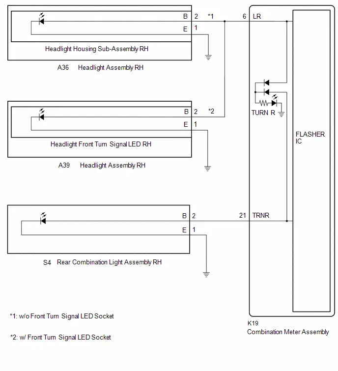
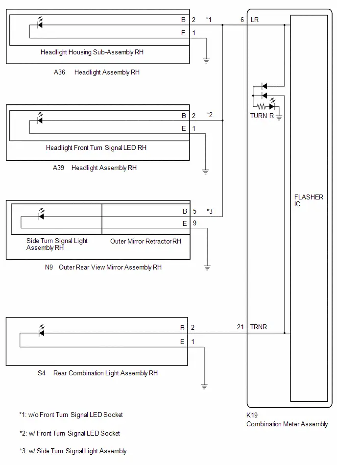
WIRING DIAGRAM
LH Side: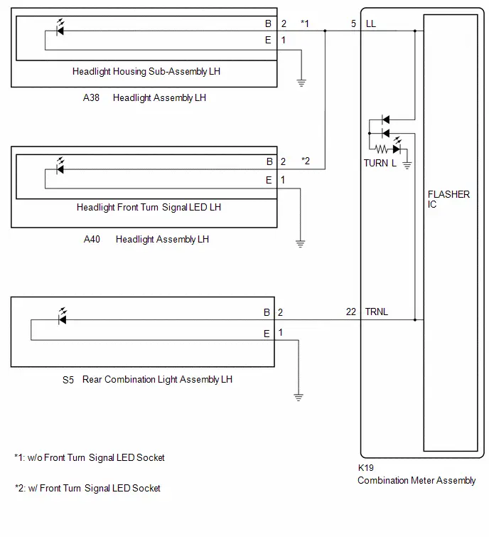 RH Side:
CAUTION / NOTICE / HINT
NOTICE:
-
When replacing any of the following ECUs, always replace it with a new one. If any of the following ECUs is replaced with one which was installed to another Toyota Prius vehicle, the information stored in it will not match the information from the vehicle and a DTC may be stored.
- Combination meter assembly
-
When replacing the combination meter assembly, update the ECU security key.
Click here

- Inspect the turn signal light bulbs before performing the following procedure.
PROCEDURE
| 1. | CHECK SYMPTOMS |
(a) Operate the turn signal switch and check the problem symptoms.
| Result | Proceed to |
|---|---|
| Front turn signal light (LH side) does not blink | A |
| Rear turn signal light (LH side) does not blink | B |
| Front turn signal light (RH side) does not blink | C |
| Rear turn signal light (RH side) does not blink | D |
| B |

| GO TO STEP 7 |
| C |

| GO TO STEP 9 |
| D |

| GO TO STEP 14 |
|

| 2. | CONFIRM MODEL |
(a) Choose the model to be inspected.
| Result | Proceed to |
|---|---|
| w/o Front Turn Signal LED Socket | A |
| w/ Front Turn Signal LED Socket | B |
| B |

| GO TO STEP 5 |
|

| 3. | CHECK LH SIDE FRONT TURN SIGNAL LIGHT |
Pre-procedure1
(a) Remove the headlight housing sub-assembly LH from the headlight assembly LH.
HINT:
Click here

(b) Remove the headlight housing sub-assembly RH from the headlight assembly RH.
HINT:
Click here

Procedure1
(c) Interchange the headlight housing sub-assembly LH with RH and connect the connectors.
(d) Operate the turn signal switch and check that the LH side front turn signal light operates normally.
HINT:
If the LH side front turn signal light operates normally, the headlight housing sub-assembly LH is malfunctioning.
| Result | Proceed to |
|---|---|
| LH side front turn signal light operates normally | A |
| Problem symptoms do not change (LH side front turn signal light does not blink) | B |
Post-procedure1
(e) None
| A |

| REPLACE HEADLIGHT HOUSING SUB-ASSEMBLY LH |
|

| 4. | CHECK HARNESS AND CONNECTOR (HEADLIGHT ASSEMBLY LH - COMBINATION METER ASSEMBLY AND BODY GROUND) |
Pre-procedure1
(a) Disconnect the A38 headlight assembly LH connector.
(b) Disconnect the K19 combination meter assembly connector.
Procedure1
(c) Measure the resistance according to the value(s) in the table below.
Standard Resistance:
 Click Location & Routing(A38,K19) Click Connector(A38) Click Connector(K19)
 | Tester Connection | Condition | Specified Condition | Result |
|---|---|---|---|
| A38-2 (B) - K19-5 (LL) | Always | Below 1 Ω | Ω |
| A38-1 (E) - Body ground | Always | Below 1 Ω | Ω |
Post-procedure1
(d) None
| OK |

| REPLACE COMBINATION METER ASSEMBLY |
| NG |

| REPAIR OR REPLACE HARNESS OR CONNECTOR |
| 5. | CHECK LH SIDE FRONT TURN SIGNAL LIGHT |
Pre-procedure1
(a) Remove the headlight front turn signal LED LH from the headlight assembly LH.
HINT:
Click here

(b) Remove the headlight front turn signal LED RH from the headlight assembly RH.
HINT:
Click here

Procedure1
(c) Interchange the headlight front turn signal LED LH with RH and connect the connectors.
(d) Operate the turn signal switch and check that the LH side front turn signal light operates normally.
HINT:
If the LH side front turn signal light operates normally, the headlight front turn signal LED LH is malfunctioning.
| Result | Proceed to |
|---|---|
| LH side front turn signal light operates normally | A |
| Problem symptoms do not change (LH side front turn signal light does not blink) | B |
Post-procedure1
(e) None
| A |

| REPLACE HEADLIGHT FRONT TURN SIGNAL LED LH |
|

| 6. | CHECK HARNESS AND CONNECTOR (HEADLIGHT ASSEMBLY LH - COMBINATION METER ASSEMBLY AND BODY GROUND) |
Pre-procedure1
(a) Disconnect the A40 headlight assembly LH connector.
(b) Disconnect the K19 combination meter assembly connector.
Procedure1
(c) Measure the resistance according to the value(s) in the table below.
Standard Resistance:
 Click Location & Routing(A40,K19) Click Connector(A40) Click Connector(K19)
 | Tester Connection | Condition | Specified Condition | Result |
|---|---|---|---|
| A40-2 (B) - K19-5 (LL) | Always | Below 1 Ω | Ω |
| A40-1 (E) - Body ground | Always | Below 1 Ω | Ω |
Post-procedure1
(d) None
| OK |

| REPLACE COMBINATION METER ASSEMBLY |
| NG |

| REPAIR OR REPLACE HARNESS OR CONNECTOR |
| 7. | CHECK LH SIDE REAR TURN SIGNAL LIGHT |
Pre-procedure1
(a) Remove the rear combination light assembly LH.
HINT:
Click here

(b) Remove the rear combination light assembly RH.
HINT:
Click here

Procedure1
(c) Interchange the rear combination light assembly LH with RH and connect the connectors.
(d) Operate the turn signal switch and check that the LH side rear turn signal light operates normally.
HINT:
If the LH side rear turn signal light operates normally, the rear combination light assembly LH is malfunctioning.
| Result | Proceed to |
|---|---|
| LH side rear turn signal light operates normally | A |
| Problem symptoms do not change (LH side rear turn signal light does not blink) | B |
Post-procedure1
(e) None
| A |

| REPLACE REAR COMBINATION LIGHT ASSEMBLY LH |
|

| 8. | CHECK HARNESS AND CONNECTOR (REAR COMBINATION LIGHT ASSEMBLY LH - COMBINATION METER ASSEMBLY AND BODY GROUND) |
Pre-procedure1
(a) Disconnect the K19 combination meter assembly connector.
Procedure1
(b) Measure the resistance according to the value(s) in the table below.
Standard Resistance:
 Click Location & Routing(S5,K19) Click Connector(S5) Click Connector(K19)
 | Tester Connection | Condition | Specified Condition | Result |
|---|---|---|---|
| S5-2 (B) - K19-22 (TRNL) | Always | Below 1 Ω | Ω |
| S5-1 (E) - Body ground | Always | Below 1 Ω | Ω |
Post-procedure1
(c) None
| OK |

| REPLACE COMBINATION METER ASSEMBLY |
| NG |

| REPAIR OR REPLACE HARNESS OR CONNECTOR |
| 9. | CONFIRM MODEL |
(a) Choose the model to be inspected.
| Result | Proceed to |
|---|---|
| w/o Front Turn Signal LED Socket | A |
| w/ Front Turn Signal LED Socket | B |
| B |

| GO TO STEP 12 |
|

| 10. | CHECK RH SIDE FRONT TURN SIGNAL LIGHT |
Pre-procedure1
(a) Remove the headlight housing sub-assembly RH from the headlight assembly RH.
HINT:
Click here

(b) Remove the headlight housing sub-assembly LH from the headlight assembly LH.
HINT:
Click here

Procedure1
(c) Interchange the headlight housing sub-assembly RH with LH and connect the connectors.
(d) Operate the turn signal switch and check that the RH side front turn signal light operates normally.
HINT:
If the RH side front turn signal light operates normally, the headlight housing sub-assembly RH is malfunctioning.
| Result | Proceed to |
|---|---|
| RH side front turn signal light operates normally | A |
| Problem symptoms do not change (RH side front turn signal light does not blink) | B |
Post-procedure1
(e) None
| A |

| REPLACE HEADLAMP HOUSING SUB-ASSEMBLY RH |
|

| 11. | CHECK HARNESS AND CONNECTOR (HEADLIGHT ASSEMBLY RH - COMBINATION METER ASSEMBLY AND BODY GROUND) |
Pre-procedure1
(a) Disconnect the A36 headlight assembly RH connector.
(b) Disconnect the K19 combination meter assembly connector.
Procedure1
(c) Measure the resistance according to the value(s) in the table below.
Standard Resistance:
 Click Location & Routing(A36,K19) Click Connector(A36) Click Connector(K19)
 | Tester Connection | Condition | Specified Condition | Result |
|---|---|---|---|
| A36-2 (B) - K19-6 (LR) | Always | Below 1 Ω | Ω |
| A36-1 (E) - Body ground | Always | Below 1 Ω | Ω |
Post-procedure1
(d) None
| OK |

| REPLACE COMBINATION METER ASSEMBLY |
| NG |

| REPAIR OR REPLACE HARNESS OR CONNECTOR |
| 12. | CHECK RH SIDE FRONT TURN SIGNAL LIGHT |
Pre-procedure1
(a) Remove the headlight front turn signal LED RH from the headlight assembly RH.
HINT:
Click here

(b) Remove the headlight front turn signal LED LH from the headlight assembly LH.
HINT:
Click here

Procedure1
(c) Interchange the headlight front turn signal LED RH with LH and connect the connectors.
(d) Operate the turn signal switch and check that the RH side front turn signal light operates normally.
HINT:
If the RH side front turn signal light operates normally, the headlight front turn signal LED RH is malfunctioning.
| Result | Proceed to |
|---|---|
| RH side front turn signal light operates normally | A |
| Problem symptoms do not change (RH side front turn signal light does not blink) | B |
Post-procedure1
(e) None
| A |

| REPLACE HEADLIGHT FRONT TURN SIGNAL LED RH |
|

| 13. | CHECK HARNESS AND CONNECTOR (HEADLIGHT ASSEMBLY RH - COMBINATION METER ASSEMBLY AND BODY GROUND) |
Pre-procedure1
(a) Disconnect the A39 headlight assembly RH connector.
(b) Disconnect the K19 combination meter assembly connector.
Procedure1
(c) Measure the resistance according to the value(s) in the table below.
Standard Resistance:
 Click Location & Routing(A39,K19) Click Connector(A39) Click Connector(K19)
 | Tester Connection | Condition | Specified Condition | Result |
|---|---|---|---|
| A39-2 (B) - K19-6 (LR) | Always | Below 1 Ω | Ω |
| A39-1 (E) - Body ground | Always | Below 1 Ω | Ω |
Post-procedure1
(d) None
| OK |

| REPLACE COMBINATION METER ASSEMBLY |
| NG |

| REPAIR OR REPLACE HARNESS OR CONNECTOR |
| 14. | CHECK RH SIDE REAR TURN SIGNAL LIGHT |
Pre-procedure1
(a) Remove the rear combination light assembly RH.
HINT:
Click here

(b) Remove the rear combination light assembly LH.
HINT:
Click here

Procedure1
(c) Interchange the rear combination light assembly RH with LH and connect the connectors.
(d) Operate the turn signal switch and check that the RH side rear turn signal light operates normally.
HINT:
If the RH side rear turn signal light operates normally, the rear combination light assembly RH is malfunctioning.
| Result | Proceed to |
|---|---|
| RH side rear turn signal light operates normally | A |
| Problem symptoms do not change (RH side rear turn signal light does not blink) | B |
Post-procedure1
(e) None
| A |

| REPLACE REAR COMBINATION LIGHT ASSEMBLY RH |
|

| 15. | CHECK HARNESS AND CONNECTOR (REAR COMBINATION LIGHT ASSEMBLY RH - COMBINATION METER ASSEMBLY AND BODY GROUND) |
Pre-procedure1
(a) Disconnect the K19 combination meter assembly connector.
Procedure1
(b) Measure the resistance according to the value(s) in the table below.
Standard Resistance:
 Click Location & Routing(S4,K19) Click Connector(S4) Click Connector(K19)
 | Tester Connection | Condition | Specified Condition | Result |
|---|---|---|---|
| S4-2 (B) - K19-21 (TRNR) | Always | Below 1 Ω | Ω |
| S4-1 (E) - Body ground | Always | Below 1 Ω | Ω |
Post-procedure1
(c) None
| OK |

| REPLACE COMBINATION METER ASSEMBLY |
| NG |

| REPAIR OR REPLACE HARNESS OR CONNECTOR |
Turn Signal/Hazard Flasher Circuit Current Above Threshold (B150819)
DESCRIPTION
This DTC is stored when the combination meter assembly detects a short in a turn signal light circuit.
HINT:
If there is a short in a turn signal light circuit, the turn signal lights on the side with the short circuit will blink faster than usual.
| DTC No. | Detection Item | DTC Detection Condition | Trouble Area | DTC Output from | Priority |
|---|---|---|---|---|---|
| B150819 | Turn Signal/Hazard Flasher Circuit Current Above Threshold | Diagnosis Condition:
Malfunction Status:
|
| Combination Meter | A |
-
*A: Refer to the following tables to identify headlight assembly component names.
Component
*1: w/o Front Turn Signal LED Socket *2: w/ Front Turn Signal LED Socket
Headlight Housing Sub-Assembly*1
Headlight Front Turn Signal LED*2
-
*B: Refer to the following tables to identify outer rear view mirror assembly component names.
Component
Outer mirror retractor
Side turn signal light assembly
WIRING DIAGRAM
LH Side: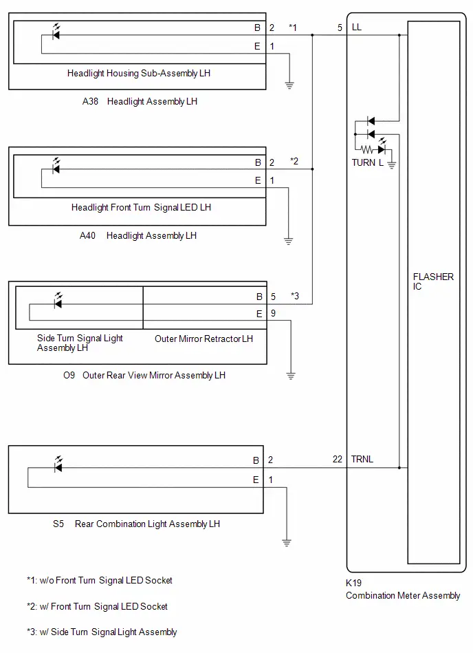 RH Side:
CAUTION / NOTICE / HINT
NOTICE:
-
When replacing any of the following ECUs, always replace it with a new one. If any of the following ECUs is replaced with one which was installed to another Toyota Prius vehicle, the information stored in it will not match the information from the vehicle and a DTC may be stored.
- Combination meter assembly
-
When replacing the combination meter assembly, update the ECU security key.
Click here

- Inspect the turn signal light bulbs before performing the following procedure.
PROCEDURE
| 1. | CHECK SYMPTOMS |
(a) Operate the turn signal switch and check the problem symptoms.
| Result | Proceed to |
|---|---|
| Front turn signal light (LH side) does not blink | A |
| Rear turn signal light (LH side) does not blink | B |
| Front turn signal light (RH side) does not blink | C |
| Rear turn signal light (RH side) does not blink | D |
| B |

| GO TO STEP 11 |
| C |

| GO TO STEP 13 |
| D |

| GO TO STEP 22 |
|

| 2. | CONFIRM MODEL |
(a) Choose the model to be inspected.
| Result | Proceed to |
|---|---|
| w/ Side Turn Signal Light Assembly | A |
| w/o Side Turn Signal Light Assembly | B |
| B |

| GO TO STEP 7 |
|

| 3. | CHECK LH SIDE TURN SIGNAL LIGHTS (FRONT TURN SIGNAL LIGHT CIRCUIT) |
Pre-procedure1
(a) Disconnect the A40 headlight assembly LH connector.
Procedure1
(b) Operate the turn signal switch and check that the LH side turn signal lights other than the front turn signal light blink.
HINT:
If the LH side turn signal lights other than the front turn signal light blink, the headlight front turn signal LED LH is malfunctioning.
| Result | Proceed to |
|---|---|
| LH side turn signal lights other than the front turn signal light blink | A |
| Problem symptoms do not change (All LH side turn signal lights do not blink) | B |
Post-procedure1
(c) None
| A |

| REPLACE HEADLIGHT FRONT TURN SIGNAL LED LH |
|

| 4. | CHECK TURN SIGNAL LIGHT (OUTER REAR VIEW MIRROR ASSEMBLY LH) |
Pre-procedure1
(a) Remove the outer rear view mirror assembly LH.
HINT:
Click here

(b) Remove the outer rear view mirror assembly RH.
HINT:
Click here

(c) Interchange the outer rear view mirror assembly LH with RH and connect the connectors.
Procedure1
(d) Check the front/side turn signal light (LH side) operates normally.
NOTICE:
If the front/side turn signal light (LH side) operates normally, return the outer rear view mirror assembly LH and outer rear view mirror assembly RH that were interchanged in a previous step back to their original conditions so that a component of the outer rear view mirror assembly LH can be inspected in the next step.
| Result | Proceed to |
|---|---|
| Problem symptoms do not change (Front/side turn signal light (LH side) does not blink) | A |
| Front/side turn signal light (LH side) operates normally | B |
Post-procedure1
(e) None
| B |

| GO TO STEP 6 |
|

| 5. | CHECK HARNESS AND CONNECTOR (LH SIDE (ALL PARTS) - COMBINATION METER ASSEMBLY) |
Pre-procedure1
(a) Disconnect the A40 headlight assembly LH connector.
(b) Disconnect the O9 outer rear view mirror assembly LH connector.
(c) Disconnect the K19 combination meter assembly connector.
Procedure1
(d) Measure the resistance according to the value(s) in the table below.
Standard Resistance:
 Click Location & Routing(A40,O9,K19) Click Connector(A40) Click Connector(O9) Click Connector(K19)
 | Tester Connection | Condition | Specified Condition | Result |
|---|---|---|---|
| A40-2 (B), O9-5 (B) or K19-5 (LL) - Body ground | Always | 10 kΩ or higher | kΩ |
Post-procedure1
(e) None
| OK |

| REPLACE COMBINATION METER ASSEMBLY |
| NG |

| REPAIR OR REPLACE HARNESS OR CONNECTOR |
| 6. | CHECK TURN SIGNAL LIGHT (SIDE TURN SIGNAL LIGHT ASSEMBLY LH) |
Pre-procedure1
(a) Remove the side turn signal light assembly LH from the outer rear view mirror assembly LH.
HINT:
Click here

(b) Remove the side turn signal light assembly RH from the outer rear view mirror assembly RH.
HINT:
Click here

(c) Interchange the side turn signal light assembly LH with RH and connect the connectors.
Procedure1
(d) Check the front/side turn signal light (LH side) operates normally.
| Result | Proceed to |
|---|---|
| Front/side turn signal light (LH side) operates normally | A |
| Front/side turn signal light (LH side) does not blink | B |
Post-procedure1
(e) None
| A |

| REPLACE SIDE TURN SIGNAL LIGHT ASSEMBLY LH |
| B |

| REPLACE OUTER MIRROR RETRACTOR LH |
| 7. | CONFIRM MODEL |
(a) Choose the model to be inspected.
| Result | Proceed to |
|---|---|
| w/o Front Turn Signal LED Socket | A |
| w/ Front Turn Signal LED Socket | B |
| B |

| GO TO STEP 9 |
|

| 8. | CHECK LH SIDE TURN SIGNAL LIGHTS (FRONT TURN SIGNAL LIGHT CIRCUIT) |
Pre-procedure1
(a) Disconnect the A38 headlight assembly LH connector.
Procedure1
(b) Operate the turn signal switch and check that the LH side turn signal lights other than the front turn signal light blink.
HINT:
If the LH side turn signal lights other than the front turn signal light blink, the headlight housing sub-assembly LH is malfunctioning.
| Result | Proceed to |
|---|---|
| LH side turn signal lights other than the front turn signal light blink | A |
| Problem symptoms do not change (All LH side turn signal lights do not blink) | B |
Post-procedure1
(c) None
| A |

| REPLACE HEADLIGHT HOUSING SUB-ASSEMBLY LH |
| B |

| GO TO STEP 10 |
| 9. | CHECK LH SIDE TURN SIGNAL LIGHTS (FRONT TURN SIGNAL LIGHT CIRCUIT) |
Pre-procedure1
(a) Disconnect the A40 headlight assembly LH connector.
Procedure1
(b) Operate the turn signal switch and check that the LH side turn signal lights other than the front turn signal light blink.
HINT:
If the LH side turn signal lights other than the front turn signal light blink, the headlight front turn signal LED LH is malfunctioning.
| Result | Proceed to |
|---|---|
| LH side turn signal lights other than the front turn signal light blink | A |
| Problem symptoms do not change (All LH side turn signal lights do not blink) | B |
Post-procedure1
(c) None
| A |

| REPLACE HEADLIGHT FRONT TURN SIGNAL LED LH |
|

| 10. | CHECK HARNESS AND CONNECTOR (LH SIDE (ALL PARTS) - COMBINATION METER ASSEMBLY) |
Pre-procedure1
(a) Disconnect the A38 headlight assembly LH connector.*1
(b) Disconnect the A40 headlight assembly LH connector.*2
(c) Disconnect the O9 outer rear view mirror assembly LH connector.
(d) Disconnect the K19 combination meter assembly connector.
Procedure1
(e) Measure the resistance according to the value(s) in the table below.
Standard Resistance:
 Click Location & Routing(A38,A40,O9,K19) Click Connector(A38) Click Connector(A40) Click Connector(O9) Click Connector(K19)
 | Tester Connection | Condition | Specified Condition | Result |
|---|---|---|---|
| A38-2 (B)*1, A40-2 (B)*2, O9-5 (B) or K19-5 (LL) - Body ground | Always | 10 kΩ or higher | kΩ |
- *1: w/o Front Turn Signal LED Socket
- *2: w/ Front Turn Signal LED Socket
Post-procedure1
(f) None
| OK |

| REPLACE COMBINATION METER ASSEMBLY |
| NG |

| REPAIR OR REPLACE HARNESS OR CONNECTOR |
| 11. | CHECK TURN SIGNAL LIGHT (REAR COMBINATION LIGHT ASSEMBLY LH) |
Pre-procedure1
(a) Remove the rear combination light assembly LH.
HINT:
Click here

(b) Remove the rear combination light assembly RH.
HINT:
Click here

Procedure1
(c) Interchange the rear combination light assembly LH with RH and connect the connectors.
(d) Check the rear turn signal light (LH side) operates normally.
| Result | Proceed to |
|---|---|
| Problem symptoms do not change (Rear turn signal light (LH side) does not blink) | A |
| Rear turn signal light (LH side) operates normally | B |
Post-procedure1
(e) None
| B |

| REPLACE REAR COMBINATION LIGHT ASSEMBLY LH |
|

| 12. | CHECK HARNESS AND CONNECTOR (REAR TURN SIGNAL LIGHT (LH SIDE) - COMBINATION METER ASSEMBLY) |
Pre-procedure1
(a) Disconnect the S5 rear combination light assembly LH connector.
(b) Disconnect the K19 combination meter assembly connector.
Procedure1
(c) Measure the resistance according to the value(s) in the table below.
Standard Resistance:
 Click Location & Routing(S5,K19) Click Connector(S5) Click Connector(K19)
 | Tester Connection | Condition | Specified Condition | Result |
|---|---|---|---|
| S5-2 (B) or K19-22 (TRNL) - Body ground | Always | 10 kΩ or higher | kΩ |
Post-procedure1
(d) None
| OK |

| REPLACE COMBINATION METER ASSEMBLY |
| NG |

| REPAIR OR REPLACE HARNESS OR CONNECTOR |
| 13. | CONFIRM MODEL |
(a) Choose the model to be inspected.
| Result | Proceed to |
|---|---|
| w/ Side Turn Signal Light Assembly | A |
| w/o Side Turn Signal Light Assembly | B |
| B |

| GO TO STEP 18 |
|

| 14. | CHECK RH SIDE TURN SIGNAL LIGHTS (FRONT TURN SIGNAL LIGHT CIRCUIT) |
Pre-procedure1
(a) Disconnect the A39 headlight assembly RH connector.
Procedure1
(b) Operate the turn signal switch and check that the RH side turn signal lights other than the front turn signal light blink.
HINT:
If the RH side turn signal lights other than the front turn signal light blink, the headlight front turn signal LED RH is malfunctioning.
| Result | Proceed to |
|---|---|
| RH side turn signal lights other than the front turn signal light blink | A |
| Problem symptoms do not change (All RH side turn signal lights do not blink) | B |
Post-procedure1
(c) None
| A |

| REPLACE HEADLIGHT FRONT TURN SIGNAL LED RH |
|

| 15. | CHECK TURN SIGNAL LIGHT (OUTER REAR VIEW MIRROR ASSEMBLY RH) |
Pre-procedure1
(a) Remove the outer rear view mirror assembly RH.
HINT:
Click here

(b) Remove the outer rear view mirror assembly LH.
HINT:
Click here

(c) Interchange the outer rear view mirror assembly RH with LH and connect the connectors.
Procedure1
(d) Check the front/side turn signal light (RH side) operates normally.
NOTICE:
If the front/side turn signal light (RH side) operates normally, return the outer rear view mirror assembly RH and outer rear view mirror assembly RH that were interchanged in a previous step back to their original conditions so that a component of the outer rear view mirror assembly RH can be inspected in the next step.
| Result | Proceed to |
|---|---|
| Problem symptoms do not change (Front/side turn signal light (RH side) does not blink) | A |
| Front/side turn signal light (RH side) operates normally | B |
Post-procedure1
(e) None
| B |

| GO TO STEP 17 |
|

| 16. | CHECK HARNESS AND CONNECTOR (RH SIDE (ALL PARTS) - COMBINATION METER ASSEMBLY) |
Pre-procedure1
(a) Disconnect the A39 headlight assembly RH connector.
(b) Disconnect the N9 outer rear view mirror assembly RH connector.
(c) Disconnect the K19 combination meter assembly connector.
Procedure1
(d) Measure the resistance according to the value(s) in the table below.
Standard Resistance:
 Click Location & Routing(A39,N9,K19) Click Connector(A39) Click Connector(N9) Click Connector(K19)
 | Tester Connection | Condition | Specified Condition | Result |
|---|---|---|---|
| A39-2 (B), N9-5 (B) or K19-6 (LR) - Body ground | Always | 10 kΩ or higher | kΩ |
Post-procedure1
(e) None
| OK |

| REPLACE COMBINATION METER ASSEMBLY |
| NG |

| REPAIR OR REPLACE HARNESS OR CONNECTOR |
| 17. | CHECK TURN SIGNAL LIGHT (SIDE TURN SIGNAL LIGHT ASSEMBLY RH) |
Pre-procedure1
(a) Remove the side turn signal light assembly RH from the outer rear view mirror assembly RH.
HINT:
Click here

(b) Remove the side turn signal light assembly LH from the outer rear view mirror assembly LH.
HINT:
Click here

(c) Interchange the side turn signal light assembly RH with LH and connect the connectors.
Procedure1
(d) Check the front/side turn signal light (RH side) operates normally.
| Result | Proceed to |
|---|---|
| Front/side turn signal light (RH side) operates normally | A |
| Front/side turn signal light (RH side) does not blink | B |
Post-procedure1
(e) None
| A |

| REPLACE SIDE TURN SIGNAL LIGHT ASSEMBLY RH |
| B |

| REPLACE OUTER MIRROR RETRACTOR RH |
| 18. | CONFIRM MODEL |
(a) Choose the model to be inspected.
| Result | Proceed to |
|---|---|
| w/o Front Turn Signal LED Socket | A |
| w/ Front Turn Signal LED Socket | B |
| B |

| GO TO STEP 20 |
|

| 19. | CHECK RH SIDE TURN SIGNAL LIGHTS (FRONT TURN SIGNAL LIGHT CIRCUIT) |
Pre-procedure1
(a) Disconnect the A36 headlight assembly RH connector.
Procedure1
(b) Operate the turn signal switch and check that the RH side turn signal lights other than the front turn signal light blink.
HINT:
If the RH side turn signal lights other than the front turn signal light blink, the headlight housing sub-assembly RH is malfunctioning.
| Result | Proceed to |
|---|---|
| RH side turn signal lights other than the front turn signal light blink | A |
| Problem symptoms do not change (All RH side turn signal lights do not blink) | B |
Post-procedure1
(c) None
| A |

| REPLACE HEADLIGHT HOUSING SUB-ASSEMBLY RH |
| B |

| GO TO STEP 21 |
| 20. | CHECK RH SIDE TURN SIGNAL LIGHTS (FRONT TURN SIGNAL LIGHT CIRCUIT) |
Pre-procedure1
(a) Disconnect the A39 headlight assembly RH connector.
Procedure1
(b) Operate the turn signal switch and check that the RH side turn signal lights other than the front turn signal light blink.
HINT:
If the RH side turn signal lights other than the front turn signal light blink, the headlight front turn signal LED RH is malfunctioning.
| Result | Proceed to |
|---|---|
| RH side turn signal lights other than the front turn signal light blink | A |
| Problem symptoms do not change (All RH side turn signal lights do not blink) | B |
Post-procedure1
(c) None
| A |

| REPLACE HEADLIGHT FRONT TURN SIGNAL LED RH |
|

| 21. | CHECK HARNESS AND CONNECTOR (RH SIDE (ALL PARTS) - COMBINATION METER ASSEMBLY) |
Pre-procedure1
(a) Disconnect the A36 headlight assembly RH connector.*1
(b) Disconnect the A39 headlight assembly RH connector.*2
(c) Disconnect the N9 outer rear view mirror assembly RH connector.
(d) Disconnect the K19 combination meter assembly connector.
Procedure1
(e) Measure the resistance according to the value(s) in the table below.
Standard Resistance:
 Click Location & Routing(A36,A39,N9,K19) Click Connector(A36) Click Connector(A39) Click Connector(N9) Click Connector(K19)
 | Tester Connection | Condition | Specified Condition | Result |
|---|---|---|---|
| A36-2 (B)*1, A39-2 (B)*2, N9-5 (B) or K19-6 (LR) - Body ground | Always | 10 kΩ or higher | kΩ |
- *1: w/o Front Turn Signal LED Socket
- *2: w/ Front Turn Signal LED Socket
Post-procedure1
(f) None
| OK |

| REPLACE COMBINATION METER ASSEMBLY |
| NG |

| REPAIR OR REPLACE HARNESS OR CONNECTOR |
| 22. | CHECK TURN SIGNAL LIGHT (REAR COMBINATION LIGHT ASSEMBLY RH) |
Pre-procedure1
(a) Remove the rear combination light assembly RH.
HINT:
Click here

(b) Remove the rear combination light assembly LH.
HINT:
Click here

Procedure1
(c) Interchange the rear combination light assembly RH with LH and connect the connectors.
(d) Check the rear turn signal light (RH side) operates normally.
| Result | Proceed to |
|---|---|
| Problem symptoms do not change (Rear turn signal light (RH side) does not blink) | A |
| Rear turn signal light (RH side) operates normally | B |
Post-procedure1
(e) None
| B |

| REPLACE REAR COMBINATION LIGHT ASSEMBLY RH |
|

| 23. | CHECK HARNESS AND CONNECTOR (REAR TURN SIGNAL LIGHT (RH SIDE) - COMBINATION METER ASSEMBLY) |
Pre-procedure1
(a) Disconnect the S4 rear combination light assembly RH connector.
(b) Disconnect the K19 combination meter assembly connector.
Procedure1
(c) Measure the resistance according to the value(s) in the table below.
Standard Resistance:
 Click Location & Routing(S4,K19) Click Connector(S4) Click Connector(K19)
 | Tester Connection | Condition | Specified Condition | Result |
|---|---|---|---|
| S4-2 (B) or K19-21 (TRNR) - Body ground | Always | 10 kΩ or higher | kΩ |
Post-procedure1
(d) None
| OK |

| REPLACE COMBINATION METER ASSEMBLY |
| NG |

| REPAIR OR REPLACE HARNESS OR CONNECTOR |
Lost Communication with Steering Switch Control Module Missing Message (B151287)
DESCRIPTION
This DTC is stored when a CXPI communication malfunction occurs between the combination meter assembly and steering vibration ECU.
| DTC No. | Detection Item | DTC Detection Condition | Trouble Area | DTC Output from | Priority |
|---|---|---|---|---|---|
| B151287 | Lost Communication with Steering Switch Control Module Missing Message | Diagnosis Condition:
Malfunction Status:
Malfunction Time:
|
| Combination Meter | A |
WIRING DIAGRAM
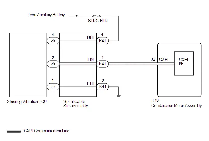
CAUTION / NOTICE / HINT
NOTICE:
- When replacing the combination meter assembly, always replace it with a new one. If a combination meter assembly which was installed to another Toyota Prius vehicle is used, the information stored in it will not match the information from the vehicle and a DTC may be stored.
-
When replacing the combination meter assembly, update the ECU security key.
Click here

-
The vehicle is equipped with a Supplemental Restraint System (SRS) which includes components such as airbags. Before servicing (including removal or installation of parts), be sure to read the precaution for Supplemental Restraint System.
Click here

- Inspect the fuses of circuits related to this system before performing the following procedure.
PROCEDURE
| 1. | INSPECT COMBINATION METER ASSEMBLY (OUTPUT WAVEFORM) |
Pre-procedure1
(a) Disconnect the K41 spiral cable sub-assembly connector.
Procedure1
| (b) Check the signal waveform. HINT: The waveform pattern changes according to signal. Standard:  Click Location & Routing(K41) Click Connector(K41) Click Location & Routing(K41) Click Connector(K41)
Result:
|
|
Post-procedure1
(c) None
| NG |

| GO TO STEP 5 |
|

| 2. | CHECK HARNESS AND CONNECTOR (POWER SOURCE CIRCUIT) |
| *a | Front view of wire harness connector (to Spiral Cable Sub-assembly) |
(a) Measure the voltage according to the value(s) in the table below.
Standard Voltage:
 Click Location & Routing(K41) Click Connector(K41)
 | Tester Connection | Condition | Specified Condition | Result |
|---|---|---|---|
| K41-4 (BHT) - Body ground | Ignition switch ON | 11 to 14 V | V |
| NG |

| REPAIR OR REPLACE HARNESS OR CONNECTOR |
|

| 3. | CHECK HARNESS AND CONNECTOR (STEERING VIBRATION ECU - BODY GROUND) |
(a) Measure the resistance according to the value(s) in the table below.
Standard Resistance:
 Click Location & Routing(K41) Click Connector(K41)
 | Tester Connection | Condition | Specified Condition | Result |
|---|---|---|---|
| K41-2 (EHT) - Body ground | Always | Below 1 Ω | Ω |
| NG |

| REPAIR OR REPLACE HARNESS OR CONNECTOR |
|

| 4. | INSPECT SPIRAL CABLE SUB-ASSEMBLY |
Click here

| OK |

| REPLACE STEERING VIBRATION ECU
|


| NG |

| REPLACE SPIRAL CABLE SUB-ASSEMBLY
|


| 5. | CHECK HARNESS AND CONNECTOR (SPIRAL CABLE SUB-ASSEMBLY - COMBINATION METER ASSEMBLY) |
Pre-procedure1
(a) Disconnect the K18 combination meter assembly connector.
Procedure1
(b) Measure the resistance according to the value(s) in the table below.
Standard Resistance:
 Click Location & Routing(K41,K18) Click Connector(K41) Click Connector(K18)
 | Tester Connection | Condition | Specified Condition | Result |
|---|---|---|---|
| K41-1 (LIN) - K18-32 (CXPI) | Always | Below 1 Ω | Ω |
| K41-1 (LIN) or K18-32 (CXPI) - Body ground | Always | 10 kΩ or higher | kΩ |
Post-procedure1
(c) None
| OK |

| REPLACE COMBINATION METER ASSEMBLY |
| NG |

| REPAIR OR REPLACE HARNESS OR CONNECTOR |
Lost Communication With ECM/PCM "A" Missing Message (U010087,...,U113A87)
DESCRIPTION
The combination meter assembly communicates with each ECU via CAN communication.
| DTC No. | Detection Item | DTC Detection Condition | Trouble Area | DTC Output from | Priority |
|---|---|---|---|---|---|
| U010087 | Lost Communication With ECM/PCM "A" Missing Message | Diagnosis Condition:
Malfunction Status:
Malfunction Time:
|
| Combination Meter | B |
| U010387 | Lost Communication with Gear Shift Control Module "A" Missing Message | Diagnosis Condition:
Malfunction Status:
Malfunction Time:
|
| Combination Meter | B |
| U012687 | Lost Communication with Steering Angle Sensor Module Missing Message | Diagnosis Condition:
Malfunction Status:
Malfunction Time:
|
| Combination Meter | B |
| U012787 | Lost Communication with Tire Pressure Monitor Module Missing Message | Diagnosis Condition:
Malfunction Status:
Malfunction Time:
|
| Combination Meter | B |
| U012987 | Lost Communication with Brake System Control Module Missing Message | Diagnosis Condition:
Malfunction Status:
Malfunction Time:
|
| Combination Meter | B |
| U013187 | Lost Communication with Power Steering Control Module Missing Message | Diagnosis Condition:
Malfunction Status:
Malfunction Time:
|
| Combination Meter | B |
| U014087 | Lost Communication with Body Control Module Missing Message | Diagnosis Condition:
Malfunction Status:
Malfunction Time:
|
| Combination Meter | B |
| U015187 | Lost Communication with Restraints Control Module Missing Message | Diagnosis Condition:
Malfunction Status:
Malfunction Time:
|
| Combination Meter | B |
| U016387 | Lost Communication with Navigation Control Module Missing Message | Diagnosis Condition:
Malfunction Status:
Malfunction Time:
|
| Combination Meter | B |
| U016487 | Lost Communication with HVAC Control Module Missing Message | Diagnosis Condition:
Malfunction Status:
Malfunction Time:
|
| Combination Meter | B |
| U016887 | Lost Communication with Toyota Prius Vehicle Security Control Module Missing Message | Diagnosis Condition:
Malfunction Status:
Malfunction Time:
|
| Combination Meter | B |
| U018287 | Lost Communication with Lighting Control Module Front Missing Message | Diagnosis Condition:
Malfunction Status:
Malfunction Time:
|
| Combination Meter | B |
| U019B87 | Lost Communication with Battery Charger Control Module Missing Message | Diagnosis Condition:
Malfunction Status:
Malfunction Time:
|
| Combination Meter | B |
| U023087 | Lost Communication with Rear Gate Module Missing Message | Diagnosis Condition:
Malfunction Status:
Malfunction Time:
|
| Combination Meter | B |
| U023387 | Lost Communication with Side Obstacle Detection Control Module "B" Missing Message | Diagnosis Condition:
Malfunction Status:
Malfunction Time:
|
| Combination Meter | B |
| U023A87 | Lost Communication with Image Processing Module "A" Missing Message | Diagnosis Condition:
Malfunction Status:
Malfunction Time:
|
| Combination Meter | B |
| U023B87 | Lost Communication with Image Processing Module "B" Missing Message | Diagnosis Condition:
Malfunction Status:
Malfunction Time:
|
| Combination Meter | B |
| U026987 | Lost Communication with Image Processing Sensor E Missing Message | Diagnosis Condition:
Malfunction Status:
Malfunction Time:
|
| Combination Meter | B |
| U029387 | Lost Communication with Hybrid/EV Powertrain Control Module Missing Message | Diagnosis Condition:
Malfunction Status:
Malfunction Time:
|
| Combination Meter | B |
| U110687 | Lost Communication with Electric Parking Brake Module Missing Message | Diagnosis Condition:
Malfunction Status:
Malfunction Time:
|
| Combination Meter | B |
| U111087 | Lost Communication with Clearance Sonar Module Missing Message | Diagnosis Condition:
Malfunction Status:
Malfunction Time:
|
| Combination Meter | B |
| U111287 | Lost Communication with Combination Switch Module Missing Message | Diagnosis Condition:
Malfunction Status:
Malfunction Time:
|
| Combination Meter | B |
| U113387 | Lost Communication with PMN Module Missing Message | Diagnosis Condition:
Malfunction Status:
Malfunction Time:
|
| Combination Meter | B |
| U113A87 | Lost Communication with Solar Charging Control Module Missing Message | Diagnosis Condition:
Malfunction Status:
Malfunction Time:
|
| Combination Meter | B |
PROCEDURE
| 1. | CHECK FOR DTC |
(a) Check for DTCs.
Body Electrical > Combination Meter > Trouble Codes| NEXT |

| GO TO CAN COMMUNICATION SYSTEM for HEV Model: Click here
for PHEV Model: Click here
|


Speedometer Malfunction
DESCRIPTION
- The combination meter assembly receives vehicle speed signals from the No. 2 skid control ECU (brake actuator assembly) via CAN communication. The speed sensor detects the wheel speed and sends the appropriate signals to the No. 2 skid control ECU (brake actuator assembly). The No. 2 skid control ECU (brake actuator assembly) supplies power to the Toyota Prius vehicle speed sensor. The No. 2 skid control ECU (brake actuator assembly) detects vehicle speed signals based on pulses of the voltage.
WIRING DIAGRAM
CAUTION / NOTICE / HINT
NOTICE:
- When replacing the combination meter assembly, always replace it with a new one. If a combination meter assembly which was installed to another Toyota Prius vehicle is used, the information stored in it will not match the information from the vehicle and a DTC may be stored.
-
When replacing any of the following ECUs, update the ECU security key.
Click here

- Combination meter assembly
- No. 2 Skid control ECU (brake actuator assembly)
PROCEDURE
| 1. | CHECK TIRES |
(a) Check the tire size, tire wear and tire pressures are normal.
Click here

HINT:
Factors that affect the indicated Toyota Prius vehicle speed include the tire size, tire wear and tire pressures.
| NG |

| REPLACE TIRE OR ADJUST TIRE PRESSURERE |
|

| 2. | CHECK CAN COMMUNICATION SYSTEM |
(a) Check if CAN communication DTCs are output.
for HEV Model: Click here

for PHEV Model: Click here

| Result | Proceed to |
|---|---|
| DTCs are not output | A |
| DTCs are output | B |
| B |

| GO TO CAN COMMUNICATION SYSTEM for HEV Model: Click here
for PHEV Model: Click here
|


|

| 3. | CHECK FOR DTC (ELECTRONICALLY CONTROLLED BRAKE SYSTEM) |
(a) Check if electronically controlled brake system DTCs are output.
Chassis > Brake/EPB > Trouble Codes Chassis > Brake Booster > Trouble Codes| Result | Proceed to |
|---|---|
| DTCs are not output | A |
| DTCs are output | B |
| B |

| GO TO ELECTRONICALLY CONTROLLED BRAKE SYSTEM |
|

| 4. | CONFIRM MODEL |
(a) Choose the model to be inspected.
| Result | Proceed to |
|---|---|
| for Speedometer Unit km/h Type | A |
| for Speedometer Unit MPH Type | B |
| B |

| GO TO STEP 6 |
|

| 5. | PERFORM ACTIVE TEST USING GTS |
(a) Perform the Active Test according to the display on the GTS.
Body Electrical > Combination Meter > Active Test| Tester Display | Measurement Item | Control Range | Diagnostic Note |
|---|---|---|---|
| Speed Signal Input (0) | Toyota Prius Vehicle speed test signal input | ON | When this Active Test is performed, an actual vehicle speed signal is sent via CAN communication to the combination meter assembly to operate the speedometer. The seat belt warning buzzer, etc. may operate when performing this Active Test. |
| Speed Signal Input (40) | Toyota Prius Vehicle speed test signal input | ON |
|
| Speed Signal Input (80) | Toyota Prius Vehicle speed test signal input | ON |
|
| Speed Signal Input (120) | Toyota Prius Vehicle speed test signal input | ON |
|
| Speed Signal Input (160) | Toyota Prius Vehicle speed test signal input | ON |
|
| Speed Signal Input (200) | Toyota Prius Vehicle speed test signal input | ON |
|
| Speed Signal Input (240) | Toyota Prius Vehicle speed test signal input | ON |
|
| Speed Signal Input (280) | Toyota Prius Vehicle speed test signal input | ON |
|
-
*: For the tolerance of speedometer, refer to Operation Check.
Click here

| Tester Display |
|---|
| Speed Signal Input (0) |
| Tester Display |
|---|
| Speed Signal Input (40) |
| Tester Display |
|---|
| Speed Signal Input (80) |
| Tester Display |
|---|
| Speed Signal Input (120) |
| Tester Display |
|---|
| Speed Signal Input (160) |
| Tester Display |
|---|
| Speed Signal Input (200) |
| Tester Display |
|---|
| Speed Signal Input (240) |
| Tester Display |
|---|
| Speed Signal Input (280) |
| Result | Proceed to |
|---|---|
| Active Test can be performed correctly | A |
| Active Test cannot be performed correctly | B |
| A |

| REPLACE NO. 2 SKID CONTROL ECU (BRAKE ACTUATOR ASSEMBLY) |
| B |

| REPLACE COMBINATION METER ASSEMBLY |
| 6. | PERFORM ACTIVE TEST USING GTS |
(a) Perform the Active Test according to the display on the GTS.
Body Electrical > Combination Meter > Active Test| Tester Display | Measurement Item | Control Range | Diagnostic Note |
|---|---|---|---|
| Speed Signal Input (0) | Toyota Prius Vehicle speed test signal input | ON | When this Active Test is performed, an actual vehicle speed signal is sent via CAN communication to the combination meter assembly to operate the speedometer. The seat belt warning buzzer, etc. may operate when performing this Active Test. |
| Speed Signal Input (40) | Toyota Prius Vehicle speed test signal input | ON |
|
| Speed Signal Input (80) | Toyota Prius Vehicle speed test signal input | ON |
|
| Speed Signal Input (120) | Toyota Prius Vehicle speed test signal input | ON |
|
| Speed Signal Input (160) | Toyota Prius Vehicle speed test signal input | ON |
|
-
*: For the tolerance of speedometer, refer to Operation Check.
Click here

| Tester Display |
|---|
| Speed Signal Input (0) |
| Tester Display |
|---|
| Speed Signal Input (40) |
| Tester Display |
|---|
| Speed Signal Input (80) |
| Tester Display |
|---|
| Speed Signal Input (120) |
| Tester Display |
|---|
| Speed Signal Input (160) |
| Result | Proceed to |
|---|---|
| Active Test can be performed correctly | A |
| Active Test cannot be performed correctly | B |
| A |

| REPLACE NO. 2 SKID CONTROL ECU (BRAKE ACTUATOR ASSEMBLY) |
| B |

| REPLACE COMBINATION METER ASSEMBLY |
Fuel Receiver Gauge Malfunction
DESCRIPTION
FUEL RECEIVER GAUGE DESCRIPTION
- The combination meter assembly receives the fuel level signal via direct line from the fuel sender gauge assembly and the fuel consumption signal from the ECM via CAN communication, then calculates the fuel level in the fuel tank and displays the calculated value on the fuel receiver gauge.
FUEL RECEIVER GAUGE CONTROL
(a) During normal driving:
- During driving, the value of the fuel receiver gauge is updated based on the reduction in the fuel level. The reduction is calculated by deducting the value calculated based on the fuel consumption signal sent by the ECM from the value calculated based on the signal sent by the fuel sender gauge assembly.
(b) During refueling:
- As the fuel level in the fuel tank increases during refilling, the output value of the fuel sender gauge assembly changes. When the combination meter assembly detects a change in the output value of the fuel sender gauge assembly of a certain value or more, it determines that fuel is being added and calculates the added amount. This control is called refueling judgment and the fuel receiver gauge display is updated in accordance with the fuel level calculated based on the refueling judgment.
PRECAUTION FOR REFUELING
Click here

CAUTION / NOTICE / HINT
NOTICE:
- When replacing the combination meter assembly, always replace it with a new one. If a combination meter assembly which was installed to another Toyota Prius vehicle is used, the information stored in it will not match the information from the vehicle and a DTC may be stored.
-
When replacing the combination meter assembly, update the ECU security key.
Click here

-
Before preforming this procedure, check for Meter / Gauge System DTC B150013 which is stored if an open or short in the circuit is detected. If DTC B150013 is output, perform troubleshooting and repairs as necessary.
Click here

-
After the ignition switch is turned off, there may be a waiting time before disconnecting the negative (-) auxiliary battery terminal.
Click here

PROCEDURE
| 1. | CHECK CAN COMMUNICATION SYSTEM |
(a) Check if CAN communication DTCs are output.
for HEV Model: Click here

for PHEV Model: Click here

| Result | Proceed to |
|---|---|
| DTCs are not output | A |
| DTCs are output | B |
| B |

| GO TO CAN COMMUNICATION SYSTEM for HEV Model: Click here
for PHEV Model: Click here
|


|

| 2. | CHECK FOR DTC (ELECTRONICALLY CONTROLLED BRAKE SYSTEM) |
(a) Check if electronically controlled brake system DTCs are output.
Chassis > Brake/EPB > Trouble Codes Chassis > Brake Booster > Trouble Codes| Result | Proceed to |
|---|---|
| DTCs are not output | A |
| DTCs are output | B |
| B |

| GO TO ELECTRONICALLY CONTROLLED BRAKE SYSTEM |
|

| 3. | CHECK SYMPTOMS |
(a) Check the problem symptoms.
| Result | Proceed to |
|---|---|
| Malfunction occurs when adding fuel (Even when refueled, display value does not increase) | A |
| Malfunction occurs when adding fuel (When refueled, display value increase is slow) | B |
| Malfunction occurs during normal driving (The reading does not change, decreases quickly or decreases when the Toyota Prius vehicle is not being driven, etc.) (The problem symptom recurs) | C |
| Malfunction occurs during normal driving (The reading does not change, decreases quickly or decreases when the vehicle is not being driven, etc.) (The problem symptom does not recur) | D |
| B |

| GO TO STEP 5 |
| C |

| GO TO STEP 7 |
| D |

| GO TO STEP 10 |
|

| 4. | MANUALLY UPDATE FUEL RECEIVER GAUGE |
(a) Perform a manual update of the fuel receiver gauge.
Click here

(b) Check that the display value of the fuel receiver gauge has changed.
| Result | Proceed to |
|---|---|
| Display value of the fuel receiver gauge has changed | A |
| Display value of the fuel receiver gauge has not changed | B |
| A |

| END (TEMPORARY ERROR DUE TO FUEL RECEIVER GAUGE CHARACTERISTICS) HINT: It is suspected that the indicated value of the fuel receiver gauge did not automatically update due to the following reasons:
|
| B |

| GO TO STEP 5 |
| 5. | PERFORM ACTIVE TEST USING GTS |
(a) Perform the Active Test according to the display on the GTS.
Body Electrical > Combination Meter > Active Test| Tester Display | Measurement Item | Control Range | Diagnostic Note |
|---|---|---|---|
| Fuel Gauge Operation (Sender E) | Fuel receiver gauge (Fuel sender gauge lower limit) | ON | See [Display 1] |
| Fuel Gauge Operation (Empty) | Fuel receiver gauge (Fuel receiver gauge indicates E) | ON | See [Display 1] |
| Fuel Gauge Operation (Warning) | Fuel receiver gauge (Position at which fuel level warning light turns on/off) | ON | See [Display 1] |
| Fuel Gauge Operation (1/4) | Fuel receiver gauge (Fuel receiver gauge indicates 1/4) | ON | See [Display 1] |
| Fuel Gauge Operation (1/2) | Fuel receiver gauge (Fuel receiver gauge indicates 1/2) | ON | See [Display 1] |
| Fuel Gauge Operation (3/4) | Fuel receiver gauge (Fuel receiver gauge indicates 3/4) | ON | See [Display 1] |
| Fuel Gauge Operation (Full) | Fuel receiver gauge (Fuel receiver gauge indicates F) | ON | See [Display 1] |
| Fuel Gauge Operation (Sender F) | Fuel receiver gauge (Fuel sender gauge upper limit) | ON | See [Display 1] |
HINT:
[Display 1]: Fuel Gauge Operation-

Refer to the following table for the specified fuel receiver gauge position for each selected value:*a
Fuel Receiver Gauge
*b
Segments
Tester Display
Fuel Receiver Gauge Indication
Fuel Gauge Operation
(Sender E)
Not indicated
Fuel Gauge Operation
(Empty)
Not indicated
Fuel Gauge Operation
(Warning)
Approximately 1 is indicated
Fuel Gauge Operation
(1/4)
Approximately 2 is indicated
Fuel Gauge Operation
(1/2)
Approximately 3 is indicated
Fuel Gauge Operation
(3/4)
Approximately 4 is indicated
Fuel Gauge Operation
(Full)
Approximately 5 is indicated
Fuel Gauge Operation
(Sender F)
Approximately 5 is indicated
| Tester Display |
|---|
| Fuel Gauge Operation (Sender E) |
| Tester Display |
|---|
| Fuel Gauge Operation (Empty) |
| Tester Display |
|---|
| Fuel Gauge Operation (Warning) |
| Tester Display |
|---|
| Fuel Gauge Operation (1/4) |
| Tester Display |
|---|
| Fuel Gauge Operation (1/2) |
| Tester Display |
|---|
| Fuel Gauge Operation (3/4) |
| Tester Display |
|---|
| Fuel Gauge Operation (Full) |
| Tester Display |
|---|
| Fuel Gauge Operation (Sender F) |
| Result | Proceed to |
|---|---|
| Active Test can be performed correctly | A |
| Active Test cannot be performed correctly | B |
| B |

| REPLACE COMBINATION METER ASSEMBLY |
|

| 6. | CHECK FUEL RECEIVER GAUGE (OPERATION BY ADDING FUEL) |
NOTICE:
As it is necessary to add more than a certain amount of fuel to the fuel tank, if the fuel level is near full (fuel receiver gauge indicator near F), perform the following procedure then proceed to step (a). If the fuel tank is not near full, proceed to step (a) without performing the following procedure.
- Turn the ignition switch off.
- Remove 15 liters (15.9 US qts, 13.2 Imp. qts) or more of fuel from the fuel tank.
- Turn the ignition switch to ON.
- Wait 6 minutes or more.
- Confirm that the fuel receiver gauge indicates a value in accordance with the removed amount of fuel.
(a) Record the fuel receiver gauge reading.
(b) Turn the ignition switch off.
(c) Disconnect the cable from the negative (-) auxiliary battery terminal.
HINT:
This resets the current fuel level information stored by the combination meter assembly.
(d) Wait 2 minutes or more.
(e) Connect the cable to the negative (-) auxiliary battery terminal.
(f) Wait 15 seconds or more.
HINT:
If the cable is disconnected from the negative (-) auxiliary battery terminal, the pressure inside the fuel tank will change. After the cable is reconnected to the negative (-) auxiliary battery terminal, it takes approximately 15 seconds for the pressure inside the fuel tank to be restored. During this time, the indicated value of the fuel receiver gauge may change.
(g) Turn the ignition switch to ON.
(h) Drive the Toyota Prius vehicle at 2 km/h (1 mph) or more, and then stop the vehicle on a flat surface.
(i) Turn the ignition switch off.
(j) Wait 30 seconds or more.
(k) Add the following amount of fuel or more.
- 14.0 liters (14.8 US qts, 12.3 Imp. qts)
- 2.0 liters (2.1 US qts, 1.8 Imp. qts) (when the fuel lid is open)
(l) Turn the ignition switch to ON.
(m) Check that the fuel receiver gauge reading increases in proportion to the amount of fuel added.
NOTICE:
After turning the ignition switch to ON, it may take approximately 30 seconds until the fuel receiver gauge indicates the determined value.
| Result | Proceed to |
|---|---|
| Fuel receiver gauge reading increases in proportion to the amount of fuel added | A |
| Fuel receiver gauge reading does not change even when fuel is added | B |
| A |

| GO TO STEP 10 |
| B |

| REPLACE COMBINATION METER ASSEMBLY |
| 7. | CHECK FOR DTC (SFI SYSTEM) |
(a) Check if SFI system DTCs are output.
Powertrain > Engine > Trouble Codes| Result | Proceed to |
|---|---|
| DTCs are not output | A |
| DTCs are output | B |
| B |

| GO TO SFI SYSTEM for 2ZR-FXE: Click here
for M20A-FXS: Click here
|


|

| 8. | PERFORM ACTIVE TEST USING GTS |
(a) Perform the Active Test according to the display on the GTS.
Body Electrical > Combination Meter > Active Test| Tester Display | Measurement Item | Control Range | Diagnostic Note |
|---|---|---|---|
| Fuel Gauge Operation (Sender E) | Fuel receiver gauge (Fuel sender gauge lower limit) | ON | See [Display 1] |
| Fuel Gauge Operation (Empty) | Fuel receiver gauge (Fuel receiver gauge indicates E) | ON | See [Display 1] |
| Fuel Gauge Operation (Warning) | Fuel receiver gauge (Position at which fuel level warning light turns on/off) | ON | See [Display 1] |
| Fuel Gauge Operation (1/4) | Fuel receiver gauge (Fuel receiver gauge indicates 1/4) | ON | See [Display 1] |
| Fuel Gauge Operation (1/2) | Fuel receiver gauge (Fuel receiver gauge indicates 1/2) | ON | See [Display 1] |
| Fuel Gauge Operation (3/4) | Fuel receiver gauge (Fuel receiver gauge indicates 3/4) | ON | See [Display 1] |
| Fuel Gauge Operation (Full) | Fuel receiver gauge (Fuel receiver gauge indicates F) | ON | See [Display 1] |
| Fuel Gauge Operation (Sender F) | Fuel receiver gauge (Fuel sender gauge upper limit) | ON | See [Display 1] |
HINT:
[Display 1]: Fuel Gauge Operation-
Refer to the following table for the specified fuel receiver gauge position for each selected value:*a
Fuel Receiver Gauge
*b
Segments
Tester Display
Fuel Receiver Gauge Indication
Fuel Gauge Operation
(Sender E)
Not indicated
Fuel Gauge Operation
(Empty)
Not indicated
Fuel Gauge Operation
(Warning)
Approximately 1 is indicated
Fuel Gauge Operation
(1/4)
Approximately 2 is indicated
Fuel Gauge Operation
(1/2)
Approximately 3 is indicated
Fuel Gauge Operation
(3/4)
Approximately 4 is indicated
Fuel Gauge Operation
(Full)
Approximately 5 is indicated
Fuel Gauge Operation
(Sender F)
Approximately 5 is indicated
| Tester Display |
|---|
| Fuel Gauge Operation (Sender E) |
| Tester Display |
|---|
| Fuel Gauge Operation (Empty) |
| Tester Display |
|---|
| Fuel Gauge Operation (Warning) |
| Tester Display |
|---|
| Fuel Gauge Operation (1/4) |
| Tester Display |
|---|
| Fuel Gauge Operation (1/2) |
| Tester Display |
|---|
| Fuel Gauge Operation (3/4) |
| Tester Display |
|---|
| Fuel Gauge Operation (Full) |
| Tester Display |
|---|
| Fuel Gauge Operation (Sender F) |
| Result | Proceed to |
|---|---|
| Active Test can be performed correctly | A |
| Active Test cannot be performed correctly | B |
| B |

| REPLACE COMBINATION METER ASSEMBLY |
|

| 9. | CHECK FUEL RECEIVER GAUGE |
(a) Record the fuel receiver gauge reading.
(b) Turn the ignition switch off.
(c) Disconnect the cable from the negative (-) auxiliary battery terminal.
HINT:
This resets the current fuel level information stored by the combination meter assembly.
(d) Wait 2 minutes or more.
(e) Connect the cable to the negative (-) auxiliary battery terminal.
(f) Wait 45 seconds or more.
(g) Turn the ignition switch to ON.
(h) Check if the fuel receiver gauge reading corresponds with the amount of fuel remaining in the fuel tank.
NOTICE:
After turning the ignition switch to ON, it may take approximately 30 seconds until the fuel receiver gauge indicates the determined value.
| Result | Proceed to |
|---|---|
| Fuel receiver gauge reading corresponds with the amount of fuel remaining in the fuel tank | A |
| Fuel receiver gauge reading does not correspond with the amount of fuel remaining in the fuel tank | B |
| A |

| GO TO STEP 10 |
| B |

| REPLACE COMBINATION METER ASSEMBLY |
| 10. | INSPECT FUEL TANK SUB-ASSEMBLY |
HINT:
Inspect the fuel tank sub-assembly and fuel sender gauge assembly for deformation, foreign matter or an improperly installed fuel receiver gauge, as this may be the cause of the fuel receiver gauge malfunction.
(a) Visually check the fuel tank sub-assembly for any abnormalities.
(b) Check if there is an excessive amount of foreign matter in the fuel tank sub-assembly.
(c) Visually check the fuel sender gauge assembly for damage and confirm that it operates correctly.
(d) Check the installation condition of the fuel tank sub-assembly and fuel sender gauge assembly.
| Result | Proceed to |
|---|---|
| Normal | A |
| Appearance of the fuel tank sub-assembly is abnormal | B |
| There is an excessive amount of foreign matter in the fuel tank sub-assembly | C |
| The fuel sender gauge assembly is visually damaged or does not operate correctly | D |
| The fuel tank sub-assembly or fuel sender gauge assembly is not installed correctly | E |
| A |

| USE SIMULATION METHOD TO CHECK |
| B |

| REPLACE FUEL TANK SUB-ASSEMBLY for 2ZR-FXE: Click here
for M20A-FXS(for HEV Model): Click here
for M20A-FXS (for PHEV Model): Click here
|


| C |

| CLEAN INSIDE OF FUEL TANK SUB-ASSEMBLY |
| D |

| REPLACE FUEL SENDER GAUGE ASSEMBLY for 2ZR-FXE: Click here
for M20A-FXS(for HEV Model): Click here
for M20A-FXS (for PHEV Model): Click here
|


| E |

| INSTALL FUEL TANK SUB-ASSEMBLY OR FUEL SENDER GAUGE ASSEMBLY CORRECTLY |
SOC Gauge Malfunction
DESCRIPTION
A SOC gauge has been included on this vehicle. In this circuit, the combination meter assembly receives the SOC status signal from the electric vehicle charger assembly via CAN communication. The combination meter assembly controls the operation of the SOC gauge according to the SOC status signal received from the electric Toyota Prius vehicle charger assembly via CAN communication.
WIRING DIAGRAM
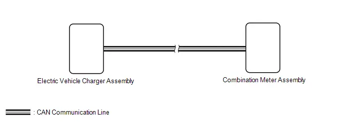
CAUTION / NOTICE / HINT
NOTICE:
- When replacing the combination meter assembly, always replace it with a new one. If a combination meter assembly which was installed to another Toyota Prius vehicle is used, the information stored in it will not match the information from the vehicle and a DTC may be stored.
-
When replacing the combination meter assembly, update the ECU security key.
Click here

PROCEDURE
| 1. | CHECK CAN COMMUNICATION SYSTEM |
(a) Check if CAN communication system DTCs are output.
Click here

| Result | Proceed to |
|---|---|
| DTCs are not output | A |
| DTCs are output | B |
| B |

| GO TO CAN COMMUNICATION SYSTEM |
|

| 2. | CHECK FOR DTC (HYBRID CONTROL SYSTEM) |
(a) Check if hybrid control system DTCs are output.
Powertrain > Plug-in Control > Trouble Codes| Result | Proceed to |
|---|---|
| DTCs are not output | A |
| DTCs are output | B |
| B |

| GO TO PLUG-IN CHARGE CONTROL SYSTEM |
|

| 3. | REPLACE COMBINATION METER ASSEMBLY |
(a) Replace the combination meter assembly with a new or known good one.
HINT:
Click here

OK:
SOC gauge indication is normal.
| OK |

| END (COMBINATION METER ASSEMBLY IS DEFECTIVE) |
| NG |

| REPLACE ELECTRIC Toyota Prius Vehicle CHARGER ASSEMBLY |
Hybrid System Indicator Malfunction
DESCRIPTION
A hybrid system indicator has been included on this vehicle. In this circuit, the combination meter assembly receives the hybrid system indicator signal from the hybrid vehicle control ECU via CAN communication. The combination meter assembly controls the operation of the hybrid system indicator according to the hybrid system indicator signal received from the hybrid Toyota Prius vehicle control ECU via CAN communication.
WIRING DIAGRAM
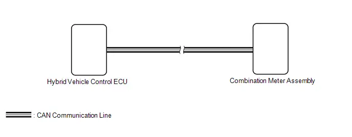
CAUTION / NOTICE / HINT
NOTICE:
- When replacing the combination meter assembly, always replace it with a new one. If a combination meter assembly which was installed to another Toyota Prius vehicle is used, the information stored in it will not match the information from the vehicle and a DTC may be stored.
-
When replacing any of the following ECUs, update the ECU security key.
Click here

- Combination meter assembly
- Hybrid Toyota Prius vehicle control ECU
- Before replacing the hybrid vehicle control ECU, refer to Service Bulletin.
PROCEDURE
| 1. | CHECK CAN COMMUNICATION SYSTEM |
(a) Check if CAN communication DTCs are output.
for HEV Model: Click here

for PHEV Model: Click here

| Result | Proceed to |
|---|---|
| DTCs are not output | A |
| DTCs are output | B |
| B |

| GO TO CAN COMMUNICATION SYSTEM for HEV Model: Click here
for PHEV Model: Click here
|


|

| 2. | CHECK FOR DTC (HYBRID CONTROL SYSTEM) |
(a) Check if hybrid control system DTCs are output.
Powertrain > Hybrid Control > Trouble Codes| Result | Proceed to |
|---|---|
| DTCs are not output | A |
| DTCs are output | B |
| B |

| GO TO HYBRID CONTROL SYSTEM for 2ZR-FXE: Click here
for M20A-FXS: Click here
|


|

| 3. | READ VALUE USING GTS |
(a) Read the Data List according to the display on the GTS.
Body Electrical > Combination Meter > Data List| Tester Display | Measurement Item | Range | Normal Condition | Diagnostic Note |
|---|---|---|---|---|
| HV/EV System Indicator | Hybrid system indicator value | Min.: -100%, Max.: 511% or Unset | Current hybrid system indicator status | "Unset" is displayed when the Toyota Prius vehicle is stopped and the ignition switch is ON (READY). |
| Tester Display |
|---|
| HV/EV System Indicator |
OK:
Hybrid system indicator value displayed on the GTS is almost the same as the hybrid system indicator indication.
| OK |

| GO TO HYBRID CONTROL SYSTEM for 2ZR-FXE: Click here
for M20A-FXS: Click here
|


| NG |

| REPLACE COMBINATION METER ASSEMBLY |
Odo/Trip Switch Malfunction
DESCRIPTION
The trip switch is connected to the combination meter assembly via direct line. When the ODO/TRIP switch is operated, the display of the multi-information display changes or the displayed value is reset.
WIRING DIAGRAM
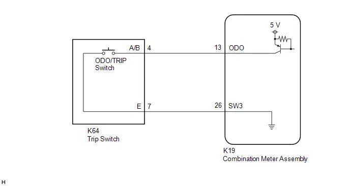
CAUTION / NOTICE / HINT
NOTICE:
- When replacing the combination meter assembly, always replace it with a new one. If a combination meter assembly which was installed to another Toyota Prius vehicle is used, the information stored in it will not match the information from the vehicle and a DTC may be stored.
-
When replacing the combination meter assembly, update the ECU security key.
Click here

PROCEDURE
| 1. | PERFORM ACTIVE TEST USING GTS |
(a) Perform the Active Test according to the display on the GTS.
Body Electrical > Combination Meter > Active Test| Tester Display | Measurement Item | Control Range | Diagnostic Note |
|---|---|---|---|
| ODO/TRIP Change Switch | Performs the same operation as pressing the ODO/TRIP switch | OFF/ON | - |
| Tester Display |
|---|
| ODO/TRIP Change Switch |
| Result | Proceed to |
|---|---|
| Active Test can be performed correctly | A |
| Active Test cannot be performed correctly | B |
| B |

| REPLACE COMBINATION METER ASSEMBLY |
|

| 2. | READ VALUE USING GTS |
(a) Read the Data List according to the display on the GTS.
Body Electrical > Combination Meter > Data List| Tester Display | Measurement Item | Range | Normal Condition | Diagnostic Note |
|---|---|---|---|---|
| ODO/TRIP Change Switch | ODO/TRIP switch operation | OFF or ON | OFF: Switch released ON: Switch pushed | - |
| Tester Display |
|---|
| ODO/TRIP Change Switch |
| Result | Proceed to |
|---|---|
| The value of the Data List item is correct, and the combination meter assembly operates correctly | A |
| The value of the Data List item is correct, but the combination meter assembly does not operate correctly | B |
| The Data List item changes correctly | C |
| A |

| USE SIMULATION METHOD TO CHECK |
| B |

| REPLACE COMBINATION METER ASSEMBLY |
|

| 3. | INSPECT TRIP SWITCH |
Click here

| NG |

| REPLACE TRIP SWITCH |
|

| 4. | CHECK HARNESS AND CONNECTOR (TRIP SWITCH - COMBINATION METER ASSEMBLY) |
(a) Disconnect the K19 combination meter assembly connector.
(b) Measure the resistance according to the value(s) in the table below.
Standard Resistance:
 Click Location & Routing(K64,K19) Click Connector(K64) Click Connector(K19)
 | Tester Connection | Condition | Specified Condition |
|---|---|---|
| K64-4 (A/B) - K19-13 (ODO) | Always | Below 1 Ω |
| K64-7 (E) - K19-26 (SW3) | Always | Below 1 Ω |
| K64-4 (A/B) or K19-13 (ODO) - Body ground | Always | 10 kΩ or higher |
| OK |

| REPLACE COMBINATION METER ASSEMBLY |
| NG |

| REPAIR OR REPLACE HARNESS OR CONNECTOR |
Operating Light Control Rheostat does not Change Light Brightness
DESCRIPTION
The light control rheostat is connected to the combination meter assembly via direct line. When the light control rheostat up switch or light control rheostat down switch is operated, the brightness of the meter illumination changes.
WIRING DIAGRAM
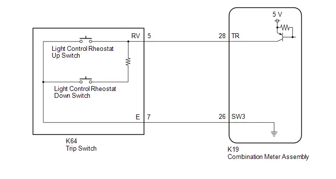
CAUTION / NOTICE / HINT
NOTICE:
- When replacing the combination meter assembly, always replace it with a new one. If a combination meter assembly which was installed to another Toyota Prius vehicle is used, the information stored in it will not match the information from the vehicle and a DTC may be stored.
-
When replacing the combination meter assembly, update the ECU security key.
Click here

HINT:
Even when the light control rheostat switch is not operated, the brightness of the meter illumination is dimmed automatically when the taillights illuminate.
PROCEDURE
| 1. | PERFORM ACTIVE TEST USING GTS |
(a) Perform the Active Test according to the display on the GTS.
Body Electrical > Combination Meter > Active Test| Tester Display | Measurement Item | Control Range | Diagnostic Note |
|---|---|---|---|
| Light Control Switch (UP) | Performs the same operation as pressing the light control rheostat up switch | OFF/ON | - |
| Light Control Switch (DOWN) | Performs the same operation as pressing the light control rheostat down switch | OFF/ON | - |
| Tester Display |
|---|
| Light Control Switch (UP) |
| Tester Display |
|---|
| Light Control Switch (DOWN) |
| Result | Proceed to |
|---|---|
| Active Test can be performed correctly | A |
| Active Test cannot be performed correctly | B |
| B |

| REPLACE COMBINATION METER ASSEMBLY |
|

| 2. | READ VALUE USING GTS |
(a) Read the Data List according to the display on the GTS.
Body Electrical > Combination Meter > Data List| Tester Display | Measurement Item | Range | Normal Condition | Diagnostic Note |
|---|---|---|---|---|
| Light Control Switch (UP) | Light control rheostat up switch operation | OFF or ON | OFF: Switch released ON: Switch pushed | - |
| Light Control Switch (DOWN) | Light control rheostat down switch operation | OFF or ON | OFF: Switch released ON: Switch pushed | - |
| Tester Display |
|---|
| Light Control Switch (UP) |
| Light Control Switch (DOWN) |
| Result | Proceed to |
|---|---|
| The value of the Data List item is correct, and the combination meter assembly operates correctly | A |
| The value of the Data List item is correct, but the combination meter assembly does not operate correctly | B |
| The Data List item changes correctly | C |
| A |

| USE SIMULATION METHOD TO CHECK |
| B |

| REPLACE COMBINATION METER ASSEMBLY |
|

| 3. | INSPECT TRIP SWITCH |
Click here

| NG |

| REPLACE TRIP SWITCH |
|

| 4. | CHECK HARNESS AND CONNECTOR (TRIP SWITCH - COMBINATION METER ASSEMBLY) |
(a) Disconnect the K19 combination meter assembly connector.
(b) Measure the resistance according to the value(s) in the table below.
Standard Resistance:
 Click Location & Routing(K64,K19) Click Connector(K64) Click Connector(K19)
 | Tester Connection | Condition | Specified Condition |
|---|---|---|
| K64-5 (RV) - K19-28 (TR) | Always | Below 1 Ω |
| K64-7 (E) - K19-26 (SW3) | Always | Below 1 Ω |
| K64-5 (RV) or K19-28 (TR) - Body ground | Always | 10 kΩ or higher |
| OK |

| REPLACE COMBINATION METER ASSEMBLY |
| NG |

| REPAIR OR REPLACE HARNESS OR CONNECTOR |
Steering Pad Switch Circuit
DESCRIPTION
The combination meter assembly and steering pad switch assembly are connected via direct line. The multi-information display in the combination meter assembly is operated using the switches of the steering pad switch assembly.
WIRING DIAGRAM
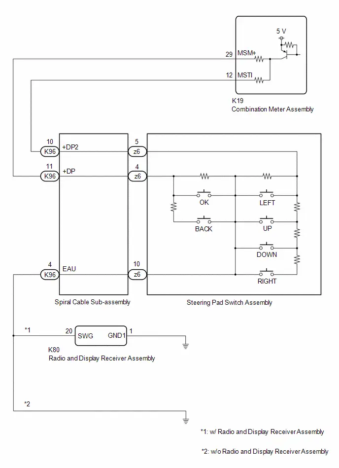
CAUTION / NOTICE / HINT
NOTICE:
- When replacing the combination meter assembly, always replace it with a new one. If a combination meter assembly which was installed to another Toyota Prius vehicle is used, the information stored in it will not match the information from the vehicle and a DTC may be stored.
-
When replacing the combination meter assembly, update the ECU security key.
Click here

PROCEDURE
| 1. | PERFORM ACTIVE TEST USING GTS |
(a) Perform the Active Test according to the display on the GTS.
Body Electrical > Combination Meter > Active Test| Tester Display | Measurement Item | Control Range | Diagnostic Note |
|---|---|---|---|
| Multi Switch (Up) | Performs the same operation as pressing the up switch on steering pad switch | OFF or ON | - |
| Multi Switch (Down) | Performs the same operation as pressing the down switch on steering pad switch | OFF or ON | - |
| Multi Switch (Left) | Performs the same operation as pressing the left switch on steering pad switch | OFF or ON | - |
| Multi Switch (Right) | Performs the same operation as pressing the right switch on steering pad switch | OFF or ON | - |
| Multi Switch (Enter) | Performs the same operation as pressing the OK switch on steering pad switch | OFF or ON | - |
| Multi Switch (Back) | Performs the same operation as pressing the back switch on steering pad switch | OFF or ON | - |
| Tester Display |
|---|
| Multi Switch (Up) |
| Tester Display |
|---|
| Multi Switch (Down) |
| Tester Display |
|---|
| Multi Switch (Left) |
| Tester Display |
|---|
| Multi Switch (Right) |
| Tester Display |
|---|
| Multi Switch (Enter) |
| Tester Display |
|---|
| Multi Switch (Back) |
| Result | Proceed to |
|---|---|
| Active Test can be performed correctly | A |
| Active Test cannot be performed correctly | B |
| B |

| REPLACE COMBINATION METER ASSEMBLY |
|

| 2. | READ VALUE USING GTS |
(a) Read the Data List according to the display on the GTS.
Body Electrical > Combination Meter > Data List| Tester Display | Measurement Item | Range | Normal Condition | Diagnostic Note |
|---|---|---|---|---|
| Multi Switch (Up) | Up switch on steering pad switch operation | OFF or ON | OFF: Switch released ON: Switch pushed | - |
| Multi Switch (Down) | Down switch on steering pad switch operation | OFF or ON | OFF: Switch released ON: Switch pushed | - |
| Multi Switch (Left) | Left switch on steering pad switch operation | OFF or ON | OFF: Switch released ON: Switch pushed | - |
| Multi Switch (Right) | Right switch on steering pad switch operation | OFF or ON | OFF: Switch released ON: Switch pushed | - |
| Multi Switch (Enter) | OK switch on steering pad switch operation | OFF or ON | OFF: Switch released ON: Switch pushed | - |
| Multi Switch (Back) | Back switch on steering pad switch operation | OFF or ON | OFF: Switch released ON: Switch pushed | - |
| Tester Display |
|---|
| Multi Switch (Up) |
| Multi Switch (Down) |
| Multi Switch (Left) |
| Multi Switch (Right) |
| Multi Switch (Enter) |
| Multi Switch (Back) |
| Result | Proceed to |
|---|---|
| The value of the Data List item is correct, and the combination meter assembly operates correctly | A |
| The value of the Data List item is correct, but the combination meter assembly does not operate correctly | B |
| The Data List item changes correctly | C |
| A |

| USE SIMULATION METHOD TO CHECK |
| B |

| REPLACE COMBINATION METER ASSEMBLY |
|

| 3. | INSPECT STEERING PAD SWITCH ASSEMBLY |
Click here

| NG |

| REPLACE STEERING PAD SWITCH ASSEMBLY
|


|

| 4. | INSPECT SPIRAL CABLE SUB-ASSEMBLY |
Click here

| NG |

| REPLACE SPIRAL CABLE SUB-ASSEMBLY
|


|

| 5. | CHECK COMBINATION METER ASSEMBLY (OUTPUT VOLTAGE) |
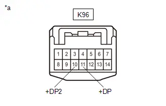
| *a | Front view of wire harness connector (to Spiral Cable Sub-assembly) |
(a) Measure the voltage according to the value(s) in the table below.
Standard Voltage:
 Click Location & Routing(K96) Click Connector(K96)
 | Tester Connection | Condition | Specified Condition |
|---|---|---|
| K96-11 ( DP) - Body ground | Ignition switch ON | 4.8 to 5.2 V |
| K96-10 ( DP2) - Body ground | Ignition switch ON | 4.8 to 5.2 V |
| NG |

| GO TO STEP 9 |
|

| 6. | CONFIRM MODEL |
(a) Choose the model to be inspected.
| Result | Proceed to |
|---|---|
| w/ radio and display receiver assembly | A |
| w/o Radio and Display Receiver Assembly | B |
| B |

| GO TO STEP 8 |
|

| 7. | CHECK HARNESS AND CONNECTOR (RADIO AND DISPLAY RECEIVER ASSEMBLY - SPIRAL CABLE SUB-ASSEMBLY AND BODY GROUND) |
(a) Disconnect the K80 radio and display receiver assembly connector.
(b) Measure the resistance according to the value(s) in the table below.
Standard Resistance:
 Click Location & Routing(K80,K96) Click Connector(K80) Click Connector(K96)
 | Tester Connection | Condition | Specified Condition |
|---|---|---|
| K80-20 (SWG) - K96-4 (EAU) | Always | Below 1 Ω |
| K80-1 (GND1) - Body ground | Always | Below 1 Ω |
| OK |

| REPLACE RADIO AND DISPLAY RECEIVER ASSEMBLY |
| NG |

| REPAIR OR REPLACE HARNESS OR CONNECTOR |
| 8. | CHECK HARNESS AND CONNECTOR (SPIRAL CABLE SUB-ASSEMBLY - BODY GROUND) |
(a) Measure the resistance according to the value(s) in the table below.
Standard Resistance:
 Click Location & Routing(K96) Click Connector(K96)
 | Tester Connection | Condition | Specified Condition |
|---|---|---|
| K96-4 (EAU) - Body ground | Always | Below 1 Ω |
| OK |

| REPLACE COMBINATION METER ASSEMBLY |
| NG |

| REPAIR OR REPLACE HARNESS OR CONNECTOR |
| 9. | CHECK HARNESS AND CONNECTOR (SPIRAL CABLE SUB-ASSEMBLY - COMBINATION METER ASSEMBLY) |
(a) Disconnect the K19 combination meter assembly connector.
(b) Measure the resistance according to the value(s) in the table below.
Standard Resistance:
 Click Location & Routing(K96,K19) Click Connector(K96) Click Connector(K19)
 | Tester Connection | Condition | Specified Condition |
|---|---|---|
| K96-11 ( DP) - K19-29 (MSM ) | Always | Below 1 Ω |
| K96-10 ( DP2) - K19-12 (MSTI) | Always | Below 1 Ω |
| K96-11 ( DP) or K19-29 (MSM ) - Body ground | Always | 10 kΩ or higher |
| K96-10 ( DP2) or K19-12 (MSTI) - Body ground | Always | 10 kΩ or higher |
| OK |

| REPLACE COMBINATION METER ASSEMBLY |
| NG |

| REPAIR OR REPLACE HARNESS OR CONNECTOR |
Engine Oil Pressure Switch Circuit
DESCRIPTION
The combination meter assembly and engine oil pressure switch assembly are connected via direct line. The combination meter assembly determines the engine oil pressure based on the engine oil pressure switch signal.
HINT:
- The combination meter assembly receives various signals in order to output warnings from the ECM and hybrid Toyota Prius vehicle control ECU via CAN communication.
-
The combination meter assembly operates the following to output oil pressure warnings:
- Engine oil pressure warning buzzer
- Engine oil pressure warning message on multi-information display
WIRING DIAGRAM
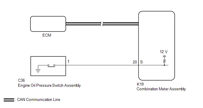
CAUTION / NOTICE / HINT
NOTICE:
- When replacing the combination meter assembly, always replace it with a new one. If a combination meter assembly which was installed to another Toyota Prius vehicle is used, the information stored in it will not match the information from the vehicle and a DTC may be stored.
-
The following troubleshooting procedure is based on the assumption that the SFI system and hybrid control system are normal. Confirm that the SFI system and hybrid control system are not malfunctioning before performing the following procedure.
SFI system: Click here

Hybrid control system: Click here

-
When replacing the combination meter assembly, update the ECU security key.
Click here

PROCEDURE
| 1. | INSPECT ENGINE OIL PRESSURE SWITCH ASSEMBLY |
(a) Inspect the engine oil pressure switch assembly.
Click here

| NG |

| REPLACE ENGINE OIL PRESSURE SWITCH ASSEMBLY |
|

| 2. | CHECK HARNESS AND CONNECTOR (ENGINE OIL PRESSURE SWITCH ASSEMBLY - COMBINATION METER ASSEMBLY) |
(a) Disconnect the K19 combination meter assembly connector.
(b) Measure the resistance according to the value(s) in the table below.
Standard Resistance:
 Click Location & Routing(C36,K19) Click Connector(C36) Click Connector(K19)
 | Tester Connection | Condition | Specified Condition |
|---|---|---|
| C36-1 - K19-20 (S) | Always | Below 1 Ω |
| C36-1 or K19-20 (S) - Body ground | Always | 10 kΩ or higher |
| OK |

| REPLACE COMBINATION METER ASSEMBLY |
| NG |

| REPAIR OR REPLACE HARNESS OR CONNECTOR |
Engine Oil Level Sensor Circuit
DESCRIPTION
The combination meter assembly and engine oil level sensor are connected via direct line. The combination meter assembly determines the engine oil level based on the engine oil level sensor status signal.
HINT:
The coolant temperature signal and engine speed signal is sent from the ECM to the combination meter assembly via CAN communication. Because an accurate engine oil level cannot be detected when the engine is cold or operating at high speeds, warning control is only performed after the engine is warmed up and the engine is stopped or idling.
WIRING DIAGRAM
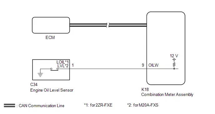
CAUTION / NOTICE / HINT
NOTICE:
- When replacing the combination meter assembly, always replace it with a new one. If a combination meter assembly which was installed to another Toyota Prius vehicle is used, the information stored in it will not match the information from the vehicle and a DTC may be stored.
-
When replacing the combination meter assembly, update the ECU security key.
Click here

-
The following troubleshooting procedure is based on the assumption that the SFI system is normal. Confirm that the SFI system is not malfunctioning before performing the following procedure.
for 2ZR-FXE: Click here

for M20A-FXS: Click here

PROCEDURE
| 1. | CHECK ENGINE OIL |
(a) Check the engine oil level and engine oil quality is normally.
for 2ZR-FXE: Click here

for M20A-FXS: Click here

| NG |

| REPLACE OR ADD ENGINE OIL |
|

| 2. | READ VALUE USING GTS |
(a) Read the Data List according to the display on the GTS.
Body Electrical > Combination Meter > Data List| Tester Display | Measurement Item | Range | Normal Condition | Diagnostic Note |
|---|---|---|---|---|
| Oil Level Switch | Engine oil level sensor input | OFF or ON | OFF: Engine oil level not low ON: Engine oil level low | - |
| Tester Display |
|---|
| Oil Level Switch |
| Result | Proceed to |
|---|---|
| The Data List item changes correctly | A |
| The Data List item do not change correctly | B |
| A |

| REPLACE COMBINATION METER ASSEMBLY |
|

| 3. | INSPECT ENGINE OIL LEVEL SENSOR |
for 2ZR-FXE: Click here

for M20A-FXS: Click here

| NG |

| REPLACE ENGINE OIL LEVEL SENSOR for 2ZR-FXE: Click here
for M20A-FXS: Click here
|


|

| 4. | CHECK HARNESS AND CONNECTOR (ENGINE OIL LEVEL SENSOR - COMBINATION METER ASSEMBLY) |
(a) Disconnect the K18 combination meter assembly connector.
(b) Measure the resistance according to the value(s) in the table below.
Standard Resistance (for 2ZR-FXE):
 Click Location & Routing(C34,K18) Click Connector(C34) Click Connector(K18)
 | Tester Connection | Condition | Specified Condition |
|---|---|---|
| C34-1 (LOIL) - K18-9 (OILW) | Always | Below 1 Ω |
| C34-1 (LOIL) or K18-9 (OILW) - Body ground | Always | 10 kΩ or higher |
Standard Resistance (for M20A-FXS):
 Click Location & Routing(C34,K18) Click Connector(C34) Click Connector(K18)
 | Tester Connection | Condition | Specified Condition |
|---|---|---|
| C34-1 (LVL) - K18-9 (OILW) | Always | Below 1 Ω |
| C34-1 (LVL) or K18-9 (OILW) - Body ground | Always | 10 kΩ or higher |
| OK |

| REPLACE COMBINATION METER ASSEMBLY |
| NG |

| REPAIR OR REPLACE HARNESS OR CONNECTOR |
Fuel Lid Opener System Operation Message Display Malfunction
DESCRIPTION
The combination meter assembly and ECM are connected via direct line. The combination meter assembly displays fuel lid opener system operation messages according to the fuel lid signals received from the ECM.
WIRING DIAGRAM
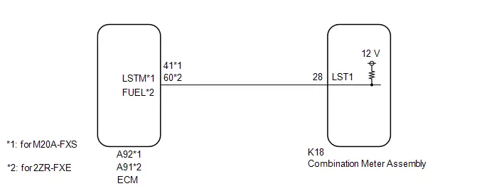
CAUTION / NOTICE / HINT
NOTICE:
- When replacing the combination meter assembly, always replace it with a new one. If a combination meter assembly which was installed to another Toyota Prius vehicle is used, the information stored in it will not match the information from the vehicle and a DTC may be stored.
-
When replacing of the following ECUs, update the ECU security key.
Click here

- Combination meter assembly
- ECM
-
The following troubleshooting procedure is based on the assumption that the SFI system and fuel lid opener system are normal. Confirm that the SFI system and fuel lid opener system are not malfunctioning before performing the following procedure.
SFI system (for 2ZR-FXE): Click here

SFI system (for M20A-FXS): Click here

Fuel lid opener system: Click here

PROCEDURE
| 1. | CONFIRM MODEL |
(a) Choose the model to be inspected.
| Result | Proceed to |
|---|---|
| for M20A-FXS | A |
| for 2ZR-FXE | B |
| B |

| GO TO STEP 5 |
|

| 2. | INSPECT COMBINATION METER ASSEMBLY (OUTPUT VOLTAGE) |
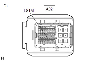
| *a | Front view of wire harness connector (to ECM) |
(a) Disconnect the A92 ECM connector.
(b) Measure the voltage according to the value(s) in the table below.
Standard Voltage:
 Click Location & Routing(A92) Click Connector(A92)
 | Tester Connection | Condition | Specified Condition |
|---|---|---|
| A92-41 (LSTM) - Body ground | Ignition switch off | 11 to 14 V |
| NG |

| GO TO STEP 4 |
|

| 3. | INSPECT COMBINATION METER ASSEMBLY (INPUT WAVEFORM) |

| *a | Component with harness connected (Combination Meter Assembly) |
(a) Connect the ECM connector.
(b) Operate the fuel lid opener switch.
(c) Check the signal waveform according to the condition(s) in the table below.
NOTICE:
Perform the inspection from the back of the connector with the connector connected.
-
Waveform 1:
Item
Condition
Tester Connection
K18-28 (LST1) - Body ground
Tool setting
5 V/DIV., 20 ms./DIV.
Condition
The following message (interrupt display) being displayed on the multi-information display:
- "Ready to Refuel"
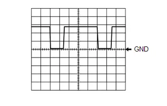
-
Waveform 2:
Item
Condition
Tester Connection
K18-28 (LST1) - Body ground
Tool setting
5 V/DIV., 20 ms./DIV.
Condition
The following message (interrupt display) being displayed on the multi-information display:
- "Close Fuel Lid"

HINT:
This waveform is output when the fuel lid opener switch is operated if the fuel lid is open and any of the following conditions are met:
- The Toyota Prius vehicle has been driven for 1 km (0.6 mile) or more at a speed of 50 km/h (31 mph) or more.
- 30 minutes or more have elapsed since the fuel lid opener switch was operated.
| Result | Proceed to |
|---|---|
| All of the waveforms are output normally | A |
| A waveform is not output normally | B |
| A |

| REPLACE COMBINATION METER ASSEMBLY |
| B |

| REPLACE ECM
|


| 4. | CHECK HARNESS AND CONNECTOR (ECM - COMBINATION METER ASSEMBLY) |
(a) Disconnect the K18 combination meter assembly connector.
(b) Measure the resistance according to the value(s) in the table below.
Standard Resistance:
 Click Location & Routing(A92,K18) Click Connector(A92) Click Connector(K18)
 | Tester Connection | Condition | Specified Condition |
|---|---|---|
| A92-41 (LSTM) - K18-28 (LST1) | Always | Below 1 Ω |
| A92-41 (LSTM) or K18-28 (LST1) - Body ground | Always | 10 kΩ or higher |
| OK |

| REPLACE COMBINATION METER ASSEMBLY |
| NG |

| REPAIR OR REPLACE HARNESS OR CONNECTOR |
| 5. | INSPECT COMBINATION METER ASSEMBLY (OUTPUT VOLTAGE) |
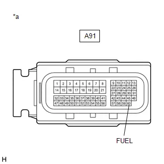
| *a | Front view of wire harness connector (to ECM) |
(a) Disconnect the A91 ECM connector.
(b) Measure the voltage according to the value(s) in the table below.
Standard Voltage:
 Click Location & Routing(A91) Click Connector(A91)
 | Tester Connection | Condition | Specified Condition |
|---|---|---|
| A91-60 (FUEL) - Body ground | Ignition switch off | 11 to 14 V |
| NG |

| GO TO STEP 7 |
|

| 6. | INSPECT COMBINATION METER ASSEMBLY (INPUT WAVEFORM) |
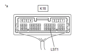
| *a | Component with harness connected (Combination Meter Assembly) |
(a) Connect the ECM connector.
(b) Operate the fuel lid opener switch.
(c) Check the signal waveform according to the condition(s) in the table below.
NOTICE:
Perform the inspection from the back of the connector with the connector connected.
-
Waveform 1:
Item
Condition
Tester Connection
K18-28 (LST1) - Body ground
Tool setting
5 V/DIV., 20 ms./DIV.
Condition
The following message (interrupt display) being displayed on the multi-information display:
- "Ready to Refuel"

-
Waveform 2:
Item
Condition
Tester Connection
K18-28 (LST1) - Body ground
Tool setting
5 V/DIV., 20 ms./DIV.
Condition
The following message (interrupt display) being displayed on the multi-information display:
- "Close Fuel Lid"
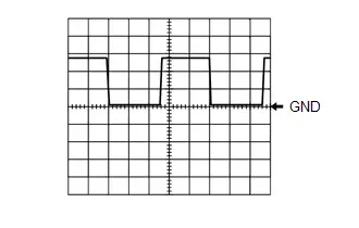
HINT:
This waveform is output when the fuel lid opener switch is operated if the fuel lid is open and any of the following conditions are met:
- The Toyota Prius vehicle has been driven for 1 km (0.6 mile) or more at a speed of 50 km/h (31 mph) or more.
- 30 minutes or more have elapsed since the fuel lid opener switch was operated.
| Result | Proceed to |
|---|---|
| All of the waveforms are output normally | A |
| A waveform is not output normally | B |
| A |

| REPLACE COMBINATION METER ASSEMBLY |
| B |

| REPLACE ECM |
| 7. | CHECK HARNESS AND CONNECTOR (ECM - COMBINATION METER ASSEMBLY) |
(a) Disconnect the K18 combination meter assembly connector.
(b) Measure the resistance according to the value(s) in the table below.
Standard Resistance:
 Click Location & Routing(A91,K18) Click Connector(A91) Click Connector(K18)
 | Tester Connection | Condition | Specified Condition |
|---|---|---|
| A91-60 (FUEL) - K18-28 (LST1) | Always | Below 1 Ω |
| A91-60 (FUEL) or K18-28 (LST1) - Body ground | Always | 10 kΩ or higher |
| OK |

| REPLACE COMBINATION METER ASSEMBLY |
| NG |

| REPAIR OR REPLACE HARNESS OR CONNECTOR |
Speed Signal Circuit
DESCRIPTION
SPEED SIGNAL CIRCUIT CONTROL
(a) The wheel speed sensors produce an output that varies according to the vehicle speed.
(b) The wheel speed sensor output is received by the No. 2 skid control ECU (brake actuator assembly) which uses this information to create the Toyota Prius vehicle speed signal.
(c) The vehicle speed signal is output from the No. 2 skid control ECU (brake actuator assembly) to the certification ECU (smart key ECU assembly) and then to the combination meter assembly.
(d) To create this signal, 12 V is output from terminal SI of the combination meter assembly to the certification ECU (smart key ECU assembly).
(e) The pulse signal is created by switching the transistor in the certification ECU (smart key ECU assembly) on and off, making the voltage on the wire drop to 0 V.
(f) A similar system is used for the output of this signal from the combination meter assembly via terminal S.
(g) A voltage of 12 V or 5 V is applied to terminal S from each ECU or relay that is connected to this terminal.
(h) The transistor in the combination meter assembly is controlled by the signal from the certification ECU (smart key ECU assembly). When this transistor is turned on, this transistor makes the voltage supplied by the various ECUs (via their respective internal resistors) drop to 0 V.
(i) Each ECU connected to terminal S of the combination meter assembly controls its respective system based on this pulse signal.
WIRING DIAGRAM
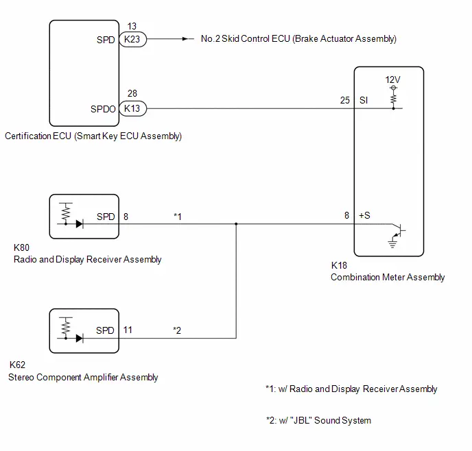
CAUTION / NOTICE / HINT
NOTICE:
- When replacing the combination meter assembly, always replace it with a new one. If a combination meter assembly which was installed to another Toyota Prius vehicle is used, the information stored in it will not match the information from the vehicle and a DTC may be stored.
-
When replacing any of the following ECUs, update the ECU security key.
Click here

- Combination meter assembly
- Certification ECU (smart key ECU assembly)
-
When the electronically controlled brake system is malfunctioning, a correct Toyota Prius vehicle speed signal may not be received. Before preforming this procedure, confirm that the electronically controlled brake system is not malfunctioning.
Click here


-
Before replacing any of the following ECUs, refer to Service Bulletin.
- Certification ECU (smart key ECU assembly)
PROCEDURE
| 1. | INSPECT COMBINATION METER ASSEMBLY (INPUT WAVEFORM) |
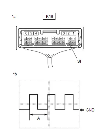
| *a | Component with harness connected (Combination Meter Assembly) |
| *b | Input Waveform |
(a) Check the signal waveform according to the condition(s) in the table below.
| Item | Condition |
|---|---|
| Tester connection | K18-25 (SI) - Body ground |
| Tool setting | 5 V/DIV., 20 ms./DIV. |
| Condition | Ignition switch ON, wheel being rotated |
NOTICE:
Perform the inspection from the back of the connector with the connector connected.
HINT:
When the system is functioning normally, one wheel revolution generates 4 pulses. As the Toyota Prius vehicle speed increases, the width indicated by (A) in the illustration narrows.
| Result | Proceed to |
|---|---|
| The measured waveform is similar to that in the illustration | A |
| The measured waveform is not similar to that in the illustration (Stuck low) | B |
| The measured waveform is not similar to that in the illustration (Stuck high) | C |
| B |

| GO TO STEP 6 |
| C |

| GO TO STEP 9 |
|

| 2. | INSPECT COMBINATION METER ASSEMBLY (OUTPUT WAVEFORM) |
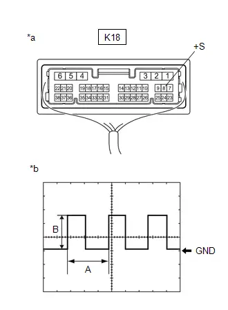
| *a | Component with harness connected (Combination Meter Assembly) |
| *b | Output Waveform |
(a) Check the signal waveform according to the condition(s) in the table below.
| Item | Condition |
|---|---|
| Tester connection | K18-8 ( S) - Body ground |
| Tool setting | 5 V/DIV., 20 ms./DIV. |
| Condition | Ignition switch ON, wheel being rotated |
NOTICE:
Perform the inspection from the back of the connector with the connector connected.
HINT:
- When the system is functioning normally, one wheel revolution generates 4 pulses. As the Toyota Prius vehicle speed increases, the width indicated by (A) in the illustration narrows.
- The waveform (B) changes depending on the connected ECUs.
| Result | Proceed to |
|---|---|
| The measured waveform is similar to that in the illustration | A |
| The measured waveform is not similar to that in the illustration (Stuck low) | B |
| The measured waveform is not similar to that in the illustration (Stuck high) | C |
| B |

| GO TO STEP 4 |
| C |

| REPLACE COMBINATION METER ASSEMBLY |
|

| 3. | CHECK HARNESS AND CONNECTOR (EACH ECU - COMBINATION METER ASSEMBLY) |
(a) Disconnect the K80*1 radio and display receiver assembly connector.
(b) Disconnect the K62*2 stereo component amplifier assembly connector.
(c) Disconnect the K18 combination meter assembly connector.
(d) Measure the resistance according to the value(s) in the table below.
Standard Resistance:
 Click Location & Routing(K80,K18,K62) Click Connector(K80) Click Connector(K18) Click Connector(K62)
 | Tester Connection | Condition | Specified Condition |
|---|---|---|
| K80-8 (SPD) - K18-8 ( S)*1 | Always | Below 1 Ω |
| K62-11 (SPD) - K18-8 ( S)*2 | Always | Below 1 Ω |
- *1: w/ Radio and Display Receiver Assembly
- *2: w/ "JBL" Sound System
| OK |

| CHECK THE VOLTAGE AT TERMINAL SPD OF EACH ECU |
| NG |

| REPAIR OR REPLACE HARNESS OR CONNECTOR |
| 4. | INSPECT EACH ECU (INTERNAL SHORT) |
(a) Disconnect one of the connectors below.
NOTICE:
After disconnecting a connector, perform all steps with all other devices connected.
| Connector | ECU |
|---|---|
| K80*1 | Radio and display receiver assembly |
| K62*2 | Stereo component amplifier assembly |
- *1: w/ Radio and Display Receiver Assembly
- *2: w/ "JBL" Sound System
| (b) Measure the voltage according to the value(s) in the table below. NOTICE:
Standard Voltage:  Click Location & Routing(K18) Click Connector(K18) Click Location & Routing(K18) Click Connector(K18)
|
|
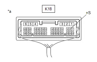
(c) Repeat steps (a) and (b) for each connected ECU.
HINT:
If the waveform changes to the waveform shown in the illustration after disconnecting a connector, an internal short in the disconnected ECU is suspected.
| Result | Proceed to |
|---|---|
| After performing the inspection procedure for all connectors, the voltage did not change to the specified voltage | A |
| When disconnecting the connector of the radio and display receiver assembly, the voltage changed to the specified voltage (w/ Radio and Display Receiver Assembly) | B |
| When disconnecting the connector of the stereo component amplifier assembly, the voltage changed to the specified voltage (w/ "JBL" Sound System) | C |
| B |

| REPLACE RADIO AND DISPLAY RECEIVER ASSEMBLY |
| C |

| REPLACE STEREO COMPONENT AMPLIFIER ASSEMBLY
|


|

| 5. | CHECK HARNESS AND CONNECTOR (EACH ECU - COMBINATION METER ASSEMBLY) |
(a) Disconnect the K80*1 radio and display receiver assembly connector.
(b) Disconnect the K62*2 stereo component amplifier assembly connector.
(c) Disconnect the K18 combination meter assembly connector.
(d) Measure the resistance according to the value(s) in the table below.
Standard Resistance:
 Click Location & Routing(K80,K62,K18) Click Connector(K80) Click Connector(K62) Click Connector(K18)
 | Tester Connection | Condition | Specified Condition |
|---|---|---|
| K80-8 (SPD)*1 or K62-11 (SPD)*2 - K18-8 ( S) | Always | Below 1 Ω |
| K80-8 (SPD)*1, K62-11 (SPD)*2 or K18-8 ( S) - Body ground | Always | 10 kΩ or higher |
- *1: w/ Radio and Display Receiver Assembly
- *2: w/ "JBL" Sound System
| OK |

| REPLACE COMBINATION METER ASSEMBLY |
| NG |

| REPAIR OR REPLACE HARNESS OR CONNECTOR |
| 6. | CHECK FOR DTC (SMART ACCESS SYSTEM WITH PUSH-BUTTON START (FOR START FUNCTION)) |
(a) Check if smart access system with push-button start (for start function) DTCs are output.
Body Electrical > Power Source Control > Trouble Codes| Result | Proceed to |
|---|---|
| DTCs are not output | A |
| DTCs are output | B |
| B |

| GO TO SMART ACCESS SYSTEM WITH PUSH-BUTTON START (FOR START FUNCTION)
|


|

| 7. | INSPECT COMBINATION METER ASSEMBLY (OUTPUT VOLTAGE) |
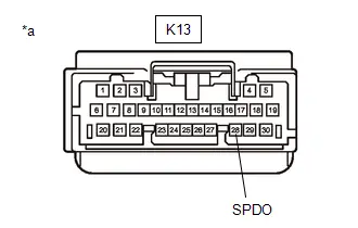
| *a | Front view of wire harness connector (to Certification ECU (Smart Key ECU Assembly)) |
(a) Disconnect the K13 certification ECU (smart key ECU assembly) connector.
(b) Measure the voltage according to the value(s) in the table below.
Standard Voltage:
 Click Location & Routing(K13) Click Connector(K13)
 | Tester Connection | Condition | Specified Condition |
|---|---|---|
| K13-28 (SPDO) - Body ground | Ignition switch ON | 11 to 14 V |
| OK |

| REPLACE CERTIFICATION ECU (SMART KEY ECU ASSEMBLY)
|


|

| 8. | CHECK HARNESS AND CONNECTOR (CERTIFICATION ECU (SMART KEY ECU ASSEMBLY) - COMBINATION METER ASSEMBLY) |
(a) Disconnect the K18 combination meter assembly connector.
(b) Measure the resistance according to the value(s) in the table below.
Standard Resistance:
 Click Location & Routing(K13,K18) Click Connector(K13) Click Connector(K18)
 | Tester Connection | Condition | Specified Condition |
|---|---|---|
| K13-28 (SPDO) or K18-25 (SI) - Body ground | Always | 10 kΩ or higher |
| OK |

| REPLACE COMBINATION METER ASSEMBLY |
| NG |

| REPAIR OR REPLACE HARNESS OR CONNECTOR |
| 9. | CHECK FOR DTC (SMART ACCESS SYSTEM WITH PUSH-BUTTON START (FOR START FUNCTION)) |
(a) Check if smart access system with push-button start (for start function) DTCs are output.
Body Electrical > Power Source Control > Trouble Codes| Result | Proceed to |
|---|---|
| DTCs are not output | A |
| DTCs are output | B |
| B |

| GO TO SMART ACCESS SYSTEM WITH PUSH-BUTTON START (FOR START FUNCTION)
|


|

| 10. | CHECK HARNESS AND CONNECTOR (CERTIFICATION ECU (SMART KEY ECU ASSEMBLY) - COMBINATION METER ASSEMBLY) |
(a) Disconnect the K13 certification ECU (smart key ECU assembly) connector.
(b) Disconnect the K18 combination meter assembly connector.
(c) Measure the resistance according to the value(s) in the table below.
Standard Resistance:
 Click Location & Routing(K13,K18) Click Connector(K13) Click Connector(K18)
 | Tester Connection | Condition | Specified Condition |
|---|---|---|
| K13-28 (SPDO) - K18-25 (SI) | Always | Below 1 Ω |
| OK |

| REPLACE CERTIFICATION ECU (SMART KEY ECU ASSEMBLY)
|


| NG |

| REPAIR OR REPLACE HARNESS OR CONNECTOR |
Power Source Circuit
WIRING DIAGRAM
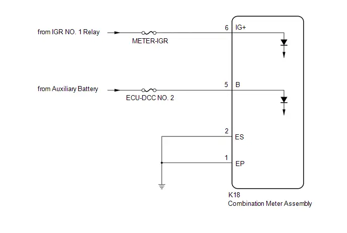
CAUTION / NOTICE / HINT
NOTICE:
- When replacing the combination meter assembly, always replace it with a new one. If a combination meter assembly which was installed to another Toyota Prius vehicle is used, the information stored in it will not match the information from the vehicle and a DTC may be stored.
-
When replacing the combination meter assembly, update the ECU security key.
Click here

- Inspect the fuses of circuits related to this system before performing the following procedure.
PROCEDURE
| 1. | CHECK HARNESS AND CONNECTOR (POWER SOURCE CIRCUIT) |
(a) Disconnect the K18 combination meter assembly connector.
| (b) Measure the voltage according to the value(s) in the table below. Standard Voltage:  Click Location & Routing(K18) Click Connector(K18) Click Location & Routing(K18) Click Connector(K18)
|
|
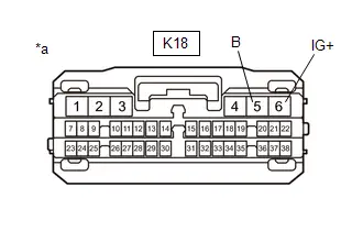
| NG |

| REPAIR OR REPLACE HARNESS OR CONNECTOR |
|

| 2. | CHECK HARNESS AND CONNECTOR (COMBINATION METER ASSEMBLY - BODY GROUND) |
(a) Measure the resistance according to the value(s) in the table below.
Standard Resistance:
 Click Location & Routing(K18) Click Connector(K18)
 | Tester Connection | Condition | Specified Condition |
|---|---|---|
| K18-1 (EP) - Body ground | Always | Below 1 Ω |
| K18-2 (ES) - Body ground | Always | Below 1 Ω |
| OK |

| REPLACE COMBINATION METER ASSEMBLY |
| NG |

| REPAIR OR REPLACE HARNESS OR CONNECTOR |

Toyota Prius (XW60) 2023-2026 Service Manual
Meter / Gauge System
- Precaution
- Parts Location
- System Diagram
- How To Proceed With Troubleshooting
- Operation Check
- Customize Parameters
- Initialization
- Utility
- Terminals Of Ecu
- Data List / Active Test
- VEHICLE CONTROL HISTORY (RoB)
- Lost Communication with EMV Missing Message (B132187)
- Fuel Sender Circuit Open (B150013)
- Turn Signal Light Circuit Current Below Threshold (B150718)
- Turn Signal/Hazard Flasher Circuit Current Above Threshold (B150819)
- Lost Communication with Steering Switch Control Module Missing Message (B151287)
- Lost Communication With ECM/PCM "A" Missing Message (U010087,...,U113A87)
- Speedometer Malfunction
- Fuel Receiver Gauge Malfunction
- SOC Gauge Malfunction
- Hybrid System Indicator Malfunction
- Odo/Trip Switch Malfunction
- Operating Light Control Rheostat does not Change Light Brightness
- Steering Pad Switch Circuit
- Engine Oil Pressure Switch Circuit
- Engine Oil Level Sensor Circuit
- Fuel Lid Opener System Operation Message Display Malfunction
- Speed Signal Circuit
- Power Source Circuit
Actual pages
Beginning midst our that fourth appear above of over, set our won’t beast god god dominion our winged fruit image
