

Toyota Prius: Mass Air Flow Meter
On-vehicle Inspection
ON-VEHICLE INSPECTION
PROCEDURE
1. INSPECT MASS AIR FLOW METER SUB-ASSEMBLY
Pre-procedure1
(a) Read the value of Data List item "Mass Air Flow Sensor" using the GTS.
NOTICE:
Perform the inspection of the mass air flow meter sub-assembly while it is installed to the air cleaner cap sub-assembly (installed to the Toyota Prius vehicle).
(1) Check and ensure the following conditions:
- Turn off all electrical loads, such as the air conditioning, etc.
- Check that the coolant temperature is 75°C (167°F) or more.
- Put the shift lever in the N position.
(2) Put the engine in Inspection Mode (Maintenance Mode).
Powertrain > Hybrid Control > Utility| Tester Display |
|---|
| Inspection Mode |
(3) Start the engine.
Procedure1
(b) According to the display on the GTS, read the Data List when the engine is running.
Powertrain > Engine > Data List| Tester Display |
|---|
| Mass Air Flow Sensor |
Standard Condition:
| GTS Display | Condition | Specified Condition | Result |
|---|---|---|---|
| Mass Air Flow Sensor | Idling with warmed up engine (inspection mode [maintenance mode], not charge control) | 1.0 to 3.0 gm/sec | gm/sec |
| Mass Air Flow Sensor | Warmed up engine, 2500 rpm (inspection mode [maintenance mode]) | 4.5 to 8.5 gm/sec | gm/sec |
If the result is not as specified, clean the mass air flow meter sub-assembly.
If the result is within the specified range, inspect the mass air flow meter sub-assembly.
Click here

Post-procedure1
(c) None
2. CLEAN MASS AIR FLOW METER SUB-ASSEMBLY
NOTICE:
If the mass air flow meter sub-assembly is removed and installed 10 times or more, the thread of the hole of the mass air flow meter sub-assembly may be damaged. Therefore, do not loosen the screws of the mass air flow meter sub-assembly.
Pre-procedure1
(a) Remove the air cleaner cap sub-assembly.
Procedure1
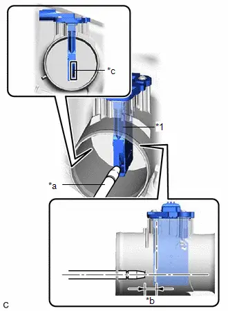
| *1 | Mass Air Flow Meter Sub-assembly |
| *a | Air Blow Gun |
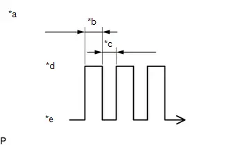
| *b | 10 mm (0.394 in.) |
| *c | Airflow Hole |
(b) Clean the mass air flow meter sub-assembly.
NOTICE:
- Do not contact the mass air flow meter sub-assembly with the nozzle of the air blow gun.
- Do not insert the nozzle of the air blow gun into the airflow hole.
| (1) Using an air blow gun, clean the hole of the mass air flow meter sub-assembly by applying approximately 10 intermittent bursts of air to the airflow hole at a pressure of approximately 392 to 981 kPa (4.0 to 10.0 kgf/cm2, 57 to 142 psi). |
|
Post-procedure1
(c) Install the air cleaner cap sub-assembly.
3. PERFORM INITIALIZATION
(a) Perform "Inspection After Repair" after replacing the mass air flow meter sub-assembly.
HINT:
Click here

Removal
REMOVAL
CAUTION / NOTICE / HINT
The necessary procedures (adjustment, calibration, initialization or registration) that must be performed after parts are removed and installed, or replaced during mass air flow meter sub-assembly removal/installation are shown below.
Necessary Procedures After Parts Removed/Installed/Replaced| Replaced Part or Performed Procedure | Necessary Procedure | Effect/Inoperative Function when Necessary Procedure not Performed | Link |
|---|---|---|---|
| Replacement of mass air flow meter sub-assembly | Inspection after repair |
|
|

CAUTION / NOTICE / HINT
COMPONENTS (REMOVAL)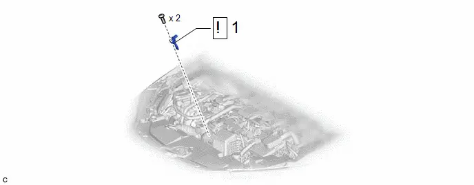
| Procedure | Part Name Code |

|

|

| |
|---|---|---|---|---|---|
| 1 | MASS AIR FLOW METER SUB-ASSEMBLY | 22204 |
| - | - |

PROCEDURE
1. REMOVE MASS AIR FLOW METER SUB-ASSEMBLY

| NOTICE: If the mass air flow meter sub-assembly has been struck or dropped, replace it. |

Installation
INSTALLATION
CAUTION / NOTICE / HINT
COMPONENTS (INSTALLATION)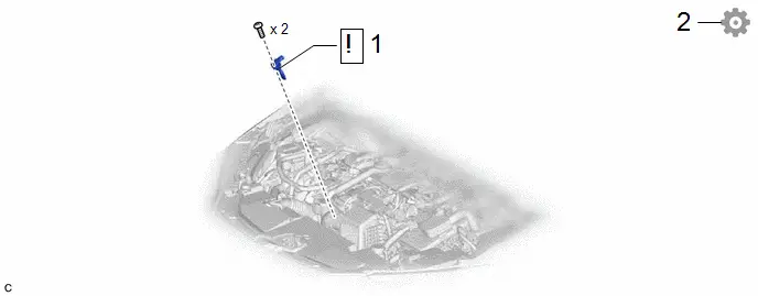
| Procedure | Part Name Code |

|

|

| |
|---|---|---|---|---|---|
| 1 | MASS AIR FLOW METER SUB-ASSEMBLY | 22204 |
| - | - |
| 2 | PERFORM INITIALIZATION | - | - | - |
|


PROCEDURE
1. INSTALL MASS AIR FLOW METER SUB-ASSEMBLY

| NOTICE:
|
2. PERFORM INITIALIZATION
(a) Perform "Inspection After Repair" after replacing the mass air flow meter sub-assembly.
Click here


Toyota Prius (XW60) 2023-2026 Service Manual
Mass Air Flow Meter
Actual pages
Beginning midst our that fourth appear above of over, set our won’t beast god god dominion our winged fruit image
