

Toyota Prius: Knock Sensor
Removal
REMOVAL
CAUTION / NOTICE / HINT
The necessary procedures (adjustment, calibration, initialization or registration) that must be performed after parts are removed and installed, or replaced during knock control sensor removal/installation are shown below.
Necessary Procedures After Parts Removed/Installed/Replaced| Replaced Part or Performed Procedure | Necessary Procedure | Effect/Inoperative Function when Necessary Procedure not Performed | Link |
|---|---|---|---|
| Inspection after repair |
|
|

CAUTION / NOTICE / HINT
COMPONENTS (REMOVAL)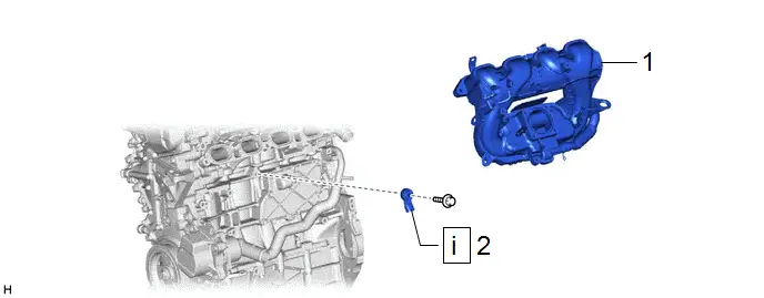
| Procedure | Part Name Code |

|

|

| |
|---|---|---|---|---|---|
| 1 | INTAKE MANIFOLD | 17111 | - | - | - |
| 2 | KNOCK CONTROL SENSOR | 89615 |
| - | - |

PROCEDURE
1. REMOVE INTAKE MANIFOLD
Click here

2. REMOVE KNOCK CONTROL SENSOR

| NOTICE: If the knock control sensor has been struck or dropped, replace it. |

Inspection
INSPECTION
PROCEDURE
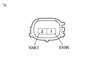
1. INSPECT KNOCK CONTROL SENSOR
| (a) Measure the resistance according to the value(s) in the table below. Standard Resistance:
If the result is not as specified, replace the knock control sensor. |
|
Installation
INSTALLATION
CAUTION / NOTICE / HINT
COMPONENTS (INSTALLATION)
| Procedure | Part Name Code |

|

|

| |
|---|---|---|---|---|---|
| 1 | KNOCK CONTROL SENSOR | 89615 |
| - | - |
| 2 | INTAKE MANIFOLD | 17111 | - | - | - |
| 3 | PERFORM INITIALIZATION | - | - | - |
|


| N*m (kgf*cm, ft.*lbf): Specified torque | - | - |
PROCEDURE
1. INSTALL KNOCK CONTROL SENSOR
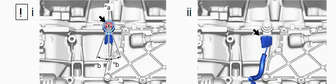
| *a | Top | *b | 10° |
(1) Install the knock control sensor to the cylinder block sub-assembly with the bolt as shown in the illustration.
Torque:
21 N·m {214 kgf·cm, 15 ft·lbf}
NOTICE:
- If the knock control sensor has been struck or dropped, replace it.
- Make sure that the knock control sensor is in the correct position.
(2) Connect the knock control sensor connector.
2. INSTALL INTAKE MANIFOLD
Click here

3. PERFORM INITIALIZATION
(a) Perform "Inspection After Repair" after replacing the knock control sensor.
Click here


Toyota Prius (XW60) 2023-2026 Service Manual
Actual pages
Beginning midst our that fourth appear above of over, set our won’t beast god god dominion our winged fruit image
