

Toyota Prius: M20a-fxs Auxiliary Battery
Removal
REMOVAL
CAUTION / NOTICE / HINT
The necessary procedures (adjustment, calibration, initialization or registration) that must be performed after parts are removed and installed, or replaced during auxiliary battery removal/installation are shown below.
HINT:
When the cable is disconnected / reconnected to the auxiliary battery terminal, systems temporarily stop operating. However, each system has a function that completes learning the first time the system is used.
Learning completes when vehicle is driven|
Effect/Inoperative Function when Necessary Procedure not Performed |
Necessary Procedure |
Link |
|---|---|---|
|
Front Camera System |
Drive the vehicle straight ahead at 35 km/h (22 mph) or more for 5 seconds or more. |
|

|
Effect/Inoperative Function when Necessary Procedure not Performed |
Necessary Procedure |
Link |
|---|---|---|
| *1: w/o Power Back Door System
*2: w/ Power Back Door System |
||
|
Power Door Lock Control System*1
|
Perform door unlock operation with door control switch or electrical key transmitter sub-assembly switch. |
|
|
Power Back Door System*2 |
Reset back door close position |
|
|
Air Conditioning System |
for HEV Model:
for PHEV Model:
|
- |


CAUTION / NOTICE / HINT
COMPONENTS (REMOVAL)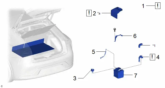
|
Procedure |
Part Name Code |
 |
 |
 |
|
|---|---|---|---|---|---|
|
1 |
PRECAUTION |
- |
|
- |
- |
|
2 |
BATTERY SERVICE HOLE COVER ASSEMBLY |
58440 |
|
- |
- |
|
3 |
NEGATIVE AUXILIARY BATTERY TERMINAL |
- |
- |
- |
- |
|
4 |
POSITIVE AUXILIARY BATTERY TERMINAL |
- |
|
- |
- |
|
5 |
BATTERY HOSE |
28885B |
- |
- |
- |
|
6 |
BATTERY CLAMP |
74481A |
- |
- |
- |
|
7 |
AUXILIARY BATTERY |
- |
- |
- |
- |


|
*1 |
FUSIBLE LINK COVER |
- |
- |
|
*a |
HINT: As the illustration shown is an example, the actual details may differ. |
- |
- |
PROCEDURE
1. PRECAUTION
 |
NOTICE:
|

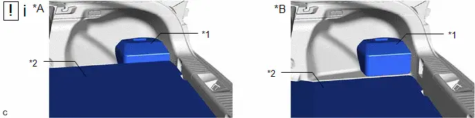
2. REMOVE BATTERY SERVICE HOLE COVER ASSEMBLY
HINT:
As the illustration shown is an example, the actual details may differ.
|
*A |
Type A |
*B |
except Type A |
|
*1 |
Battery Service Hole Cover Assembly |
*2 |
Deck Board Assembly |
(1) Using the illustration, check the specification of the deck board assembly.
|
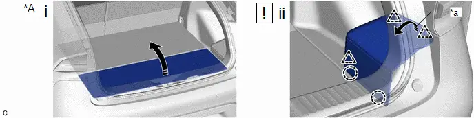
*A |
Type A |
- |
- |
|
*a |
Handle |
- |
- |
(1) Type A:
- Turn back the deck board assembly as shown in the illustration.
(2) Pull the handle to disengage the 3 clips and 2 claws and remove the battery service hole cover assembly.
3. DISCONNECT CABLE FROM NEGATIVE AUXILIARY BATTERY TERMINAL

4. DISCONNECT CABLE FROM POSITIVE AUXILIARY BATTERY TERMINAL
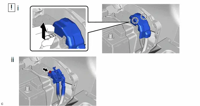
 |
Remove in this Direction |
- |
- |
(1) Place fingers on the positions shown in the illustration and pull the fusible link cover toward the front of the vehicle to disengage the claw and remove the fusible link cover.
NOTICE:
If the fusible link cover is lifted up without the claws being disengaged, the claws of the fusible link cover may be damaged.
(2) Loosen the bolt and disconnect the cable from the positive (+) auxiliary battery terminal.
5. REMOVE BATTERY HOSE

6. REMOVE BATTERY CLAMP

7. REMOVE AUXILIARY BATTERY

Installation
INSTALLATION
CAUTION / NOTICE / HINT
COMPONENTS (INSTALLATION)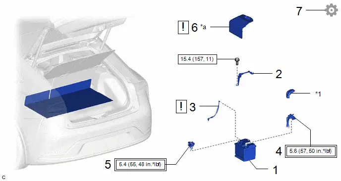
|
Procedure |
Part Name Cord |
 |
 |
 |
|
|---|---|---|---|---|---|
|
1 |
AUXILIARY BATTERY |
- |
- |
- |
- |
|
2 |
BATTERY CLAMP |
74481A |
- |
- |
- |
|
3 |
BATTERY HOSE |
28885B |
|
- |
- |
|
4 |
POSITIVE AUXILIARY BATTERY TERMINAL |
- |
- |
- |
- |
|
5 |
NEGATIVE AUXILIARY BATTERY TERMINAL |
- |
- |
- |
- |
|
6 |
BATTERY SERVICE HOLE COVER ASSEMBLY |
58440 |
|
- |
- |
|
7 |
INITIALIZATION AFTER RECONNECTING AUXILIARY BATTERY TERMINAL |
- |
- |
- |
|


|
*1 |
FUSIBLE LINK COVER |
- |
- |
|
*a |
HINT: As the illustration shown is an example, the actual details may differ. |
- |
- |
 |
Tightening torque for "Major areas involving basic vehicle performance such as moving/turning/stopping": N*m (kgf*cm, ft.*lbf) |
 |
N*m (kgf*cm, ft.*lbf): Specified torque |
PROCEDURE
1. INSTALL AUXILIARY BATTERY
2. INSTALL BATTERY CLAMP
Torque:
15.4 N·m {157 kgf·cm, 11 ft·lbf}
3. INSTALL BATTERY HOSE
 |
NOTICE: After replacing the auxiliary battery, install the ventilation hole plug supplied with the new auxiliary battery or the ventilation hole plug from the old auxiliary battery to the ventilation hole on the side to which the battery hose is not connected. HINT:
|
4. CONNECT CABLE TO POSITIVE AUXILIARY BATTERY TERMINAL
Torque:
5.6 N·m {57 kgf·cm, 50 in·lbf}
5. CONNECT CABLE TO NEGATIVE AUXILIARY BATTERY TERMINAL
Torque:
5.4 N·m {55 kgf·cm, 48 in·lbf}
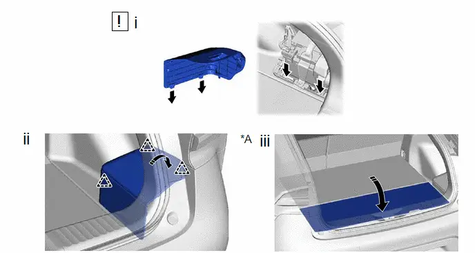
6. INSTALL BATTERY SERVICE HOLE COVER ASSEMBLY
HINT:
As the illustration shown is an example, the actual details may differ.
|
*A |
Type A |
- |
- |
(1) Insert the 2 claws of the battery service hole cover assembly into the deck trim side panel assembly RH.
(2) Engage the 3 clips of the battery service hole cover assembly.
(3) Type A:
- Return the deck board assembly to its original position.
7. INITIALIZATION AFTER RECONNECTING AUXILIARY BATTERY TERMINAL
HINT:
When disconnecting and reconnecting the auxiliary battery, there is an automatic learning function that completes learning when the respective system is used.
Click here


Toyota Prius (XW60) 2023-2026 Service Manual
M20a-fxs Auxiliary Battery
Actual pages
Beginning midst our that fourth appear above of over, set our won’t beast god god dominion our winged fruit image
