

Toyota Prius: Lin Communication System
- Precaution
- Parts Location
- System Description
- How To Proceed With Troubleshooting
- Terminals Of Ecu
- Data List / Active Test
- Diagnostic Trouble Code Chart
- P/W Master SW System Missing Message (B120687,B232187-B232487)
- LIN Communication Missing Message (B228787)
- Door LIN Bus off (B232588)
- Alarm / Wiper LIN Bus off (B276C88)
- Communication between ECUs connected by LIN Bus off (B278588)
- ID-BOX Missing Message (B278987)
- Power Source Control System Missing Message (B278C87)
Precaution
PRECAUTION
PRECAUTION FOR DISCONNECTING CABLE FROM NEGATIVE (-) AUXILIARY BATTERY TERMINAL
NOTICE:
After the ignition switch is turned off, there may be a waiting time before disconnecting the negative (-) auxiliary battery terminal.
Click here

HINT:
When disconnecting and reconnecting the auxiliary battery, there is an automatic learning function that completes learning when the respective system is used.
Click here


Parts Location
PARTS LOCATION
ILLUSTRATION
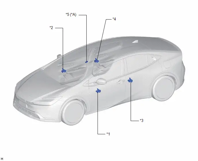
| *A | w/ Auto Wiper System | - | - |
| *1 | POWER WINDOW REGULATOR MOTOR ASSEMBLY LH (DRIVER DOOR) | *2 | POWER WINDOW REGULATOR MOTOR ASSEMBLY RH (FRONT PASSENGER DOOR) |
| *3 | POWER WINDOW REGULATOR MOTOR ASSEMBLY LH (REAR LH DOOR) | *4 | POWER WINDOW REGULATOR MOTOR ASSEMBLY RH (REAR RH DOOR) |
| *5 | RAIN SENSOR | - | - |
ILLUSTRATION
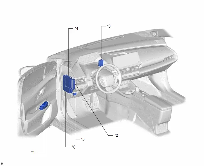
| *1 | MULTIPLEX NETWORK MASTER SWITCH ASSEMBLY | *2 | CERTIFICATION ECU (SMART KEY ECU ASSEMBLY) |
| *3 | ID CODE BOX (IMMOBILISER CODE ECU) | *4 | MAIN BODY ECU (MULTIPLEX NETWORK BODY ECU) |
| *5 | DLC3 | *6 | POWER DISTRIBUTION BOX ASSEMBLY - ECU-B NO. 1 FUSE - ECU-B NO. 2 FUSE - DOOR F/L FUSE - DOOR F/R FUSE - DOOR R/L FUSE - DOOR R/R FUSE |
System Description
SYSTEM DESCRIPTION
LIN COMMUNICATION SYSTEM DESCRIPTION
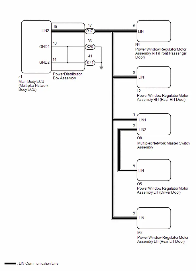
The LIN communication system is used for communication between the components in the tables below. If communication cannot be performed through LIN communication such as when there is an open or short in a communication line, the master control ECU of the relevant system will store a DTC. Refer to the table below about the communication bus lines and connected components.
HINT:
- Each component has a fail-safe function which operates in the event of a malfunction to protect the system and allow communication between other components to continue.
- In the following table, "○" indicates that the function applies, and "-" indicates that it does not.
| Component | Master Control | LIN Communication DTC Output Function |
|---|---|---|
| Main Body ECU (Multiplex Network Body ECU) | ○ | ○ |
| Power Window Regulator Motor Assembly LH (Driver Door) | - | - |
| Power Window Regulator Motor Assembly RH (Front Passenger Door) | - | - |
| Power Window Regulator Motor Assembly LH (Rear LH Door) | - | - |
| Power Window Regulator Motor Assembly RH (Rear RH Door) | - | - |
| Multiplex Network Master Switch Assembly | - | - |
| Component | Master Control | LIN Communication DTC Output Function |
|---|---|---|
| Certification ECU (Smart Key ECU Assembly) | ○ | ○ |
| ID Code Box (Immobiliser Code ECU) | - | - |
| Component | Master Control | LIN Communication DTC Output Function |
|---|---|---|
| Main Body ECU (Multiplex Network Body ECU) | ○ | ○ |
| Rain Sensor | - | - |
How To Proceed With Troubleshooting
CAUTION / NOTICE / HINT
HINT:
- Use the following procedure to troubleshoot the LIN communication system.
- *: Use the GTS.
PROCEDURE
| 1. | Toyota Prius Vehicle BROUGHT TO WORKSHOP |
|

| 2. | CUSTOMER PROBLEM ANALYSIS |
HINT:
- In troubleshooting, confirm that the problem symptoms have been accurately identified. Preconceptions should be discarded in order to make an accurate judgment. To clearly understand what the problem symptoms are, it is extremely important to ask the customer about the problem and the conditions at the time the malfunction occurred.
- Gather as much information as possible for reference. Past problems that seem unrelated may also help in some cases.
- The following 5 items are important points for problem analysis:
| What | Toyota Prius Vehicle model, system name |
| When | Date, time, occurrence frequency |
| Where | Road conditions |
| Under what conditions? | Driving conditions, weather conditions |
| How did it happen? | Problem symptoms |
|

| 3. | PRE-CHECK |
(a) Measure the auxiliary battery voltage with the ignition switch off.
Standard Voltage:
11 to 14 V
If the voltage is below 11 V, recharge or replace the auxiliary battery before proceeding to the next step.
(b) Check the fuses and relays.
(c) Check the connector connections and terminals to make sure that there are no abnormalities such as loose connections, deformation, etc.
|

| 4. | INSPECT COMMUNICATION FUNCTION OF CAN COMMUNICATION SYSTEM* |
(a) Using the GTS, check for CAN communication system DTCs.
for HEV Model: Click here

for PHEV Model: Click here

| Result | Proceed to |
|---|---|
| CAN DTCs are not output | A |
| CAN DTCs are output | B |
| B |

| GO TO CAN COMMUNICATION SYSTEM for HEV Model: Click here
for PHEV Model: Click here
|


|

| 5. | INSPECT COMMUNICATION FUNCTION OF LIN COMMUNICATION SYSTEM* |
(a) Using the GTS, check for LIN communication system DTCs.
Body Electrical > Main Body > Trouble Codes Body Electrical > Power Source Control > Trouble Codes Body Electrical > Smart Key > Trouble Codes| Result | Proceed to |
|---|---|
| LIN DTCs are not output | A |
| LIN DTCs are output | B |
| B |

| GO TO DIAGNOSTIC TROUBLE CODE CHART |
|

| 6. | OVERALL ANALYSIS AND TROUBLESHOOTING* |
(a) Terminals of ECU
Click here

(b) Data List / Active Test
Click here

|

| 7. | REPAIR OR REPLACE |
|

| 8. | CONFIRMATION TEST |
| NEXT |

| END |
Terminals Of Ecu
TERMINALS OF ECU
CHECK POWER DISTRIBUTION BOX ASSEMBLY AND MAIN BODY ECU (MULTIPLEX NETWORK BODY ECU)
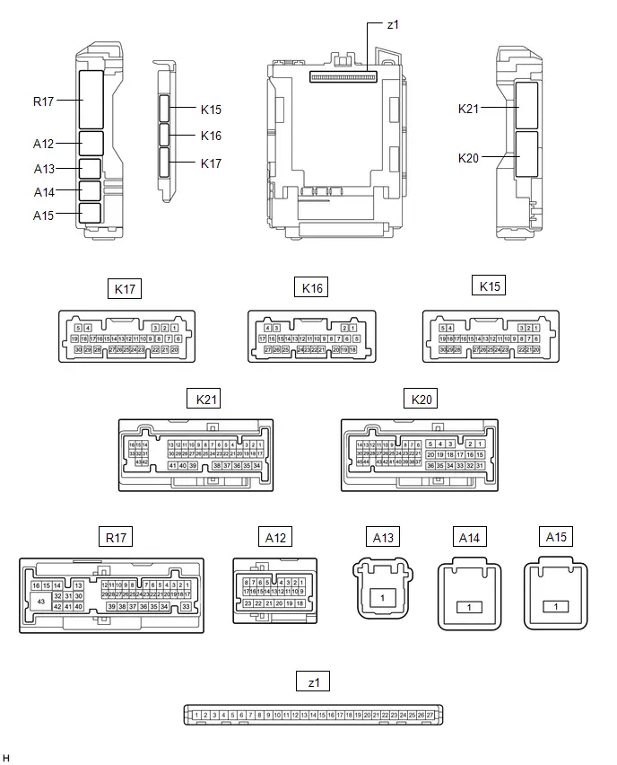
(a) Disconnect the z1 main body ECU (multiplex network body ECU) connector.
Click here


(b) Measure the voltage and resistance according to the value(s) in the table below.
HINT:
Measure the values on the wire harness side with the connectors disconnected.
| Terminal No. (Symbol) | Terminal Description | Condition | Specified Condition |
|---|---|---|---|
| z1-13 (GND1) - Body ground | Ground | Always | Below 1 Ω |
| z1-14 (GND2) - Body ground | Ground | Always | Below 1 Ω |
| z1-26 (BECU) - Body ground | Auxiliary battery power supply | Ignition switch off | 11 to 14 V |
| z1-27 (IGR) - Body ground | IG power supply | Ignition switch ON | 11 to 14 V |
| Ignition switch off | Below 1 V |
(c) Reconnect the z1 main body ECU (multiplex network body ECU) connector.
(d) Check for pulses according to the value(s) in the table below.
| Terminal No. (Symbol) | Terminal Description | Condition | Specified Condition |
|---|---|---|---|
| R17-17 - Body ground | LIN communication line | Ignition switch ON | Pulse generation |
CHECK MULTIPLEX NETWORK MASTER SWITCH ASSEMBLY
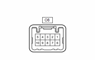
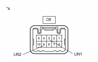
(a) Disconnect the O8 multiplex network master switch assembly connector.
(b) Measure the voltage and resistance according to the value(s) in the table below.
HINT:
Measure the values on the wire harness side with the connector disconnected.
| Terminal No. (Symbol) | Terminal Description | Condition | Specified Condition |
|---|---|---|---|
| O8-1 (B) - Body ground | Auxiliary battery power supply | Ignition switch off | 11 to 14 V |
| O8-4 (GND) - Body ground | Ground | Always | Below 1 Ω |
(c) Reconnect the O8 multiplex network master switch assembly connector.
(d) Check for pulses according to the value(s) in the table below.
| Terminal No. (Symbol) | Terminal Description | Condition | Specified Condition |
|---|---|---|---|
| O8-3 (LIN1) - Body ground | LIN communication line | Ignition switch ON | Pulse generation |
| O8-9 (LIN2) - Body ground | LIN communication line | Ignition switch ON | Pulse generation |
CHECK POWER WINDOW REGULATOR MOTOR ASSEMBLY LH (DRIVER DOOR)
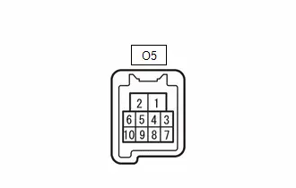
(a) Disconnect the O5 power window regulator motor assembly LH (driver door) connector.
(b) Measure the voltage and resistance according to the value(s) in the table below.
HINT:
Measure the values on the wire harness side with the connector disconnected.
| Terminal No. (Symbol) | Terminal Description | Condition | Specified Condition |
|---|---|---|---|
| O5-2 (B) - Body ground | Auxiliary battery power supply | Ignition switch off | 11 to 14 V |
| O5-1 (GND) - Body ground | Ground | Always | Below 1 Ω |
(c) Reconnect the O5 power window regulator motor assembly LH (driver door) connector.
(d) Check for pulses according to the value(s) in the table below.
| Terminal No. (Symbol) | Terminal Description | Condition | Specified Condition |
|---|---|---|---|
| O5-9 (LIN) - Body ground | LIN communication line | Ignition switch ON | Pulse generation |
CHECK POWER WINDOW REGULATOR MOTOR ASSEMBLY RH (FRONT PASSENGER DOOR)
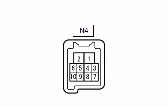
(a) Disconnect the N4 power window regulator motor assembly RH (front passenger door) connector.
(b) Measure the voltage and resistance according to the value(s) in the table below.
HINT:
Measure the values on the wire harness side with the connector disconnected.
| Terminal No. (Symbol) | Terminal Description | Condition | Specified Condition |
|---|---|---|---|
| N4-2 (B) - Body ground | Auxiliary battery power supply | Ignition switch off | 11 to 14 V |
| N4-1 (GND) - Body ground | Ground | Always | Below 1 Ω |
(c) Reconnect the N4 power window regulator motor assembly RH (front passenger door) connector.
(d) Check for pulses according to the value(s) in the table below.
| Terminal No. (Symbol) | Terminal Description | Condition | Specified Condition |
|---|---|---|---|
| N4-9 (LIN) - Body ground | LIN communication line | Ignition switch ON | Pulse generation |
CHECK POWER WINDOW REGULATOR MOTOR ASSEMBLY LH (REAR LH DOOR)

(a) Disconnect the M2 power window regulator motor assembly LH (rear LH door) connector.
(b) Measure the voltage and resistance according to the value(s) in the table below.
HINT:
Measure the values on the wire harness side with the connector disconnected.
| Terminal No. (Symbol) | Terminal Description | Condition | Specified Condition |
|---|---|---|---|
| M2-2 (B) - Body ground | Auxiliary battery power supply | Ignition switch off | 11 to 14 V |
| M2-1 (GND) - Body ground | Ground | Always | Below 1 Ω |
(c) Reconnect the M2 power window regulator motor assembly LH (rear LH door) connector.
(d) Check for pulses according to the value(s) in the table below.
| Terminal No. (Symbol) | Terminal Description | Condition | Specified Condition |
|---|---|---|---|
| M2-9 (LIN) - Body ground | LIN communication line | Ignition switch ON | Pulse generation |
CHECK POWER WINDOW REGULATOR MOTOR ASSEMBLY RH (REAR RH DOOR)
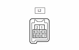
(a) Disconnect the L2 power window regulator motor assembly RH (rear RH door) connector.
(b) Measure the voltage and resistance according to the value(s) in the table below.
HINT:
Measure the values on the wire harness side with the connector disconnected.
| Terminal No. (Symbol) | Terminal Description | Condition | Specified Condition |
|---|---|---|---|
| L2-2 (B) - Body ground | Auxiliary battery power supply | Ignition switch off | 11 to 14 V |
| L2-1 (GND) - Body ground | Ground | Always | Below 1 Ω |
(c) Reconnect the L2 power window regulator motor assembly RH (rear RH door) connector.
(d) Check for pulses according to the value(s) in the table below.
| Terminal No. (Symbol) | Terminal Description | Condition | Specified Condition |
|---|---|---|---|
| L2-9 (LIN) - Body ground | LIN communication line | Ignition switch ON | Pulse generation |
CHECK CERTIFICATION ECU (SMART KEY ECU ASSEMBLY)
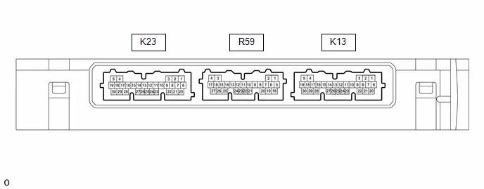
(a) Disconnect the K13 certification ECU (smart key ECU assembly) connector.
(b) Measure the voltage and resistance according to the value(s) in the table below.
HINT:
Measure the values on the wire harness side with the connector disconnected.
| Terminal No. (Symbol) | Terminal Description | Condition | Specified Condition |
|---|---|---|---|
| K13-6 ( B) - Body ground | Auxiliary battery power supply | Ignition switch off | 11 to 14 V |
| K13-29 (E) - Body ground | Ground | Always | Below 1 Ω |
(c) Reconnect the K13 certification ECU (smart key ECU assembly) connector.
(d) Check for pulses according to the value(s) in the table below.
| Terminal No. (Symbol) | Terminal Description | Condition | Specified Condition |
|---|---|---|---|
| K13-8 (LIN) - Body ground | LIN communication line | Ignition switch ON | Pulse generation |
CHECK ID CODE BOX (IMMOBILISER CODE ECU)

(a) Disconnect the K43 ID code box (immobiliser code ECU) connector.
(b) Measure the voltage and resistance according to the value(s) in the table below.
HINT:
Measure the values on the wire harness side with the connector disconnected.
| Terminal No. (Symbol) | Terminal Description | Condition | Specified Condition |
|---|---|---|---|
| K43-5 (GND) - Body ground | Ground | Always | Below 1 Ω |
| K43-1 ( B) - Body ground | B power supply | Ignition switch off | 11 to 14 V |
(c) Reconnect the K43 ID code box (immobiliser code ECU) connector.
(d) Check for pulses according to the value(s) in the table below.
| Terminal No. (Symbol) | Terminal Description | Condition | Specified Condition |
|---|---|---|---|
| K43-2 (LIN1) - Body ground | LIN communication line | Ignition switch ON | Pulse generation |
CHECK RAIN SENSOR (w/ Auto Wiper System)

(a) Check for pulses according to the value(s) in the table below.
| Terminal No. (Symbol) | Terminal Description | Condition | Specified Condition |
|---|---|---|---|
| U4-3 (MPX) - Body ground | LIN communication line | Ignition switch ON | Pulse generation |
Data List / Active Test
DATA LIST / ACTIVE TEST
DATA LIST
HINT:
Using the GTS to read the Data List allows the values or states of switches, sensors, actuators and other items to be read without removing any parts. This non-intrusive inspection can be very useful because intermittent conditions or signals may be discovered before parts or wiring is disturbed. Reading the Data List information early in troubleshooting is one way to save diagnostic time.
NOTICE:
In the table below, the values listed under "Normal Condition" are reference values. Do not depend solely on these reference values when deciding whether a part is faulty or not.
(a) Read the Data List according to the display on the GTS.
Body Electrical > Main Body > Data List| Tester Display | Measurement Item | Range | Normal Condition | Diagnostic Note |
|---|---|---|---|---|
| Communication D-Door Motor | Connection status between power window regulator motor assembly LH (driver door) and main body ECU (multiplex network body ECU) | STOP or OK | STOP: Not Connected OK: Connected | DTC is output if an error occurs in LIN communication. |
| Communication P-Door Motor | Connection status between power window regulator motor assembly RH (front passenger door) and main body ECU (multiplex network body ECU) | STOP or OK | STOP: Not Connected OK: Connected | DTC is output if an error occurs in LIN communication. |
| Communication RR-Door Motor | Connection status between power window regulator motor assembly RH (rear RH door) and main body ECU (multiplex network body ECU) | STOP or OK | STOP: Not Connected OK: Connected | DTC is output if an error occurs in LIN communication. |
| Communication RL-Door Motor | Connection status between power window regulator motor assembly LH (rear LH door) and main body ECU (multiplex network body ECU) | STOP or OK | STOP: Not Connected OK: Connected | DTC is output if an error occurs in LIN communication. |
| Communication Intrusion Sensor 1 | Connection status between map light assembly and main body ECU (multiplex network body ECU) | STOP or OK | STOP: Not Connected OK: Connected |
|
| Communication Intrusion Sensor 2 | Connection status between map light assembly and main body ECU (multiplex network body ECU) | STOP or OK | STOP: Not Connected OK: Connected |
|
| Communication Sunshade ECU | Connection status between roof sunshade ECU and main body ECU (multiplex network body ECU) | STOP or OK | STOP: Not Connected OK: Connected |
|
| Communication Slide Roof | Connection status between sliding roof ECU and main body ECU (multiplex network body ECU) | STOP or OK | STOP: Not Connected OK: Connected |
|
| Communication Humidity/Rain Sensor | Connection status between rain sensor and main body ECU (multiplex network body ECU) | STOP or OK | STOP: Not Connected OK: Connected |
|
| Communication Double Locking | Connection status between double lock door control relay assembly and main body ECU (multiplex network body ECU) | STOP or OK | STOP: Not Connected OK: Connected |
|
| Communication Master Switch | Connection status between multiplex network master switch assembly and main body ECU (multiplex network body ECU) | STOP or OK | STOP: Not Connected OK: Connected | DTC is output if an error occurs in LIN communication. |
Diagnostic Trouble Code Chart
DIAGNOSTIC TROUBLE CODE CHART
LIN Communication System| DTC No. | Detection Item | DTC Output from | Priority | Link |
|---|---|---|---|---|
| B120687 | P/W Master SW System Missing Message | Main Body | A |
|
| B228787 | LIN Communication Missing Message | Power Source Control | B |
|
| B232187 | D-Door P/W System Missing Message | Main Body | A |
|
| B232287 | P-Door P/W System Missing Message | Main Body | A |
|
| B232387 | RR-Door P/W System Missing Message | Main Body | A |
|
| B232487 | RL-Door P/W System Missing Message | Main Body | A |
|
| B232588 | Door LIN Bus off | Main Body | A |
|
| B276C88 | Alarm / Wiper LIN Bus off | Main Body | A |
|
| B278588 | Communication between ECUs connected by LIN Bus off | Smart Key | A |
|
| B278987 | ID-BOX Missing Message | Smart Key | A |
|
| B278C87 | Power Source Control System Missing Message | Smart Key | A |
|


P/W Master SW System Missing Message (B120687,B232187-B232487)
DESCRIPTION
This DTC is stored when LIN communication between the main body ECU (multiplex network body ECU) and multiplex network master switch assembly, power window regulator motor assembly LH (driver door), power window regulator motor assembly RH (front passenger door), power window regulator motor assembly RH (rear RH door) or power window regulator motor assembly LH (rear LH door) stops for 10 seconds or more.
| DTC No. | Detection Item | DTC Detection Condition | Trouble Area | DTC Output from | Priority |
|---|---|---|---|---|---|
| B120687 | P/W Master SW System Missing Message | No communication between multiplex network master switch assembly and main body ECU (multiplex network body ECU) for 10 seconds or more. |
| Main Body | A |
| B232187 | D-Door P/W System Missing Message | No communication between power window regulator motor assembly LH (driver door) and main body ECU (multiplex network body ECU) for 10 seconds or more. |
| Main Body | A |
| B232287 | P-Door P/W System Missing Message | No communication between power window regulator motor assembly RH (front passenger door) and main body ECU (multiplex network body ECU) for 10 seconds or more. |
| Main Body | A |
| B232387 | RR-Door P/W System Missing Message | No communication between power window regulator motor assembly RH (rear RH door) and main body ECU (multiplex network body ECU) for 10 seconds or more. |
| Main Body | A |
| B232487 | RL-Door P/W System Missing Message | No communication between power window regulator motor assembly LH (rear LH door) and main body ECU (multiplex network body ECU) for 10 seconds or more. |
| Main Body | A |
WIRING DIAGRAM

CAUTION / NOTICE / HINT
NOTICE:
- Inspect the fuses for circuits related to this system before performing the following procedure.
-
When a power window regulator motor assembly is replaced or removed and reinstalled, it is necessary to perform initialization.
Click here

-
Before replacing the main body ECU (multiplex network body ECU), refer to Registration.
Click here

PROCEDURE
| 1. | CLEAR DTC |
(a) Clear the DTCs.
Body Electrical > Main Body > Clear DTCs
|

| 2. | CHECK FOR DTC |
(a) Check for DTCs.
Body Electrical > Main Body > Trouble Codes| Result | Proceed to |
|---|---|
| DTCs are not output | A |
| B120687, B232187, B232287, B232387 and B232487 are output | B |
| B120687, B232187, B232387 and B232487 are output | C |
| B120687, B232187 and B232487 are output | D |
| B120687 and B232187 are output | E |
| Only B120687 is output | F |
| Only B232187 is output | G |
| Only B232287 is output | H |
| Only B232387 is output | I |
| Only B232487 is output | J |
| A |

| USE SIMULATION METHOD TO CHECK |
| C |

| GO TO STEP 5 |
| D |

| GO TO STEP 6 |
| E |

| GO TO STEP 6 |
| F |

| GO TO STEP 7 |
| G |

| GO TO STEP 8 |
| H |

| GO TO STEP 11 |
| I |

| GO TO STEP 13 |
| J |

| GO TO STEP 15 |
|

| 3. | INSPECT POWER DISTRIBUTION BOX ASSEMBLY |
Pre-procedure1
(a) Remove the power distribution box assembly.
HINT:
Click here


(b) Remove the main body ECU (multiplex network body ECU) from the power distribution box assembly.
Procedure1
(c) Measure the resistance according to the value(s) in the table below.

| *a | Component without harness connected (Power Distribution Box Assembly) | - | - |
HINT:
This inspection is to check the LIN communication line in the power distribution box assembly that connects the wire harness to the built-in main body ECU (multiplex network body ECU).
Standard Resistance:
 Click Location & Routing(z1,R17) Click Connector(z1) Click Connector(R17)
 | Tester Connection | Condition | Specified Condition | Result |
|---|---|---|---|
| z1-15 (LIN2) - R17-17 | Always | Below 1 Ω | Ω |
Post-procedure1
(d) None
| NG |

| REPLACE POWER DISTRIBUTION BOX ASSEMBLY
|


|

| 4. | CHECK HARNESS AND CONNECTOR (POWER DISTRIBUTION BOX ASSEMBLY - POWER WINDOW REGULATOR MOTOR ASSEMBLY LH (REAR LH DOOR)) |
Pre-procedure1
(a) Disconnect the M2 power window regulator motor assembly LH (rear LH door) connector.
Procedure1
(b) Measure the resistance according to the value(s) in the table below.
NOTICE:
Make sure that each ECU is in sleep mode before performing the inspection. To enter sleep mode, turn the ignition switch from ON to off and wait for 180 seconds or more without operating any switches.
Standard Resistance:
 Click Location & Routing(R17,M2) Click Connector(R17) Click Connector(M2)
 | Tester Connection | Condition | Specified Condition | Result |
|---|---|---|---|
| R17-17 - M2-9 (LIN) | Ignition switch off | Below 1 Ω | Ω |
Post-procedure1
(c) None
| OK |

| REPLACE MAIN BODY ECU (MULTIPLEX NETWORK BODY ECU)
|


| NG |

| REPAIR OR REPLACE HARNESS OR CONNECTOR |
| 5. | CHECK HARNESS AND CONNECTOR (POWER DISTRIBUTION BOX ASSEMBLY - POWER WINDOW REGULATOR MOTOR ASSEMBLY RH (FRONT PASSENGER DOOR)) |
Pre-procedure1
(a) Disconnect the R17 power distribution box assembly connector.
(b) Disconnect the N4 power window regulator motor assembly RH (front passenger door) connector.
Procedure1
(c) Measure the resistance according to the value(s) in the table below.
NOTICE:
Make sure that each ECU is in sleep mode before performing the inspection. To enter sleep mode, turn the ignition switch from ON to off and wait for 180 seconds or more without operating any switches.
Standard Resistance:
 Click Location & Routing(R17,N4) Click Connector(R17) Click Connector(N4)
 | Tester Connection | Condition | Specified Condition | Result |
|---|---|---|---|
| R17-17 - N4-9 (LIN) | Ignition switch off | Below 1 Ω | Ω |
Post-procedure1
(d) None
| OK |

| REPLACE MAIN BODY ECU (MULTIPLEX NETWORK BODY ECU)
|


| NG |

| REPAIR OR REPLACE HARNESS OR CONNECTOR |
| 6. | CHECK HARNESS AND CONNECTOR (POWER DISTRIBUTION BOX ASSEMBLY - MULTIPLEX NETWORK MASTER SWITCH ASSEMBLY) |
Pre-procedure1
(a) Disconnect the R17 power distribution box assembly connector.
(b) Disconnect the O8 multiplex network master switch assembly connector.
Procedure1
(c) Measure the resistance according to the value(s) in the table below.
NOTICE:
Make sure that each ECU is in sleep mode before performing the inspection. To enter sleep mode, turn the ignition switch from ON to off and wait for 180 seconds or more without operating any switches.
Standard Resistance:
 Click Location & Routing(R17,O8) Click Connector(R17) Click Connector(O8)
 | Tester Connection | Condition | Specified Condition | Result |
|---|---|---|---|
| R17-17 - O8-3 (LIN1) | Ignition switch off | Below 1 Ω | Ω |
Post-procedure1
(d) None
| OK |

| REPLACE MAIN BODY ECU (MULTIPLEX NETWORK BODY ECU)
|


| NG |

| REPAIR OR REPLACE HARNESS OR CONNECTOR |
| 7. | CHECK HARNESS AND CONNECTOR (MULTIPLEX NETWORK MASTER SWITCH ASSEMBLY - AUXILIARY BATTERY AND BODY GROUND) |
Pre-procedure1
(a) Disconnect the O8 multiplex network master switch assembly connector.
Procedure1
(b) Measure the voltage according to the value(s) in the table below.
Standard Voltage:
 Click Location & Routing(O8) Click Connector(O8)
 | Tester Connection | Condition | Specified Condition | Result |
|---|---|---|---|
| O8-1 (B) - Body ground | Ignition switch off | 11 to 14 V | V |
(c) Measure the resistance according to the value(s) in the table below.
Standard Resistance:
 Click Location & Routing(O8) Click Connector(O8)
 | Tester Connection | Condition | Specified Condition | Result |
|---|---|---|---|
| O8-4 (GND) - Body ground | Always | Below 1 Ω | Ω |
Post-procedure1
(d) None
| OK |

| REPLACE MULTIPLEX NETWORK MASTER SWITCH ASSEMBLY |
| NG |

| REPAIR OR REPLACE HARNESS OR CONNECTOR |
| 8. | INSPECT MULTIPLEX NETWORK MASTER SWITCH ASSEMBLY |
Pre-procedure1
(a) Remove the multiplex network master switch assembly.
HINT:
Click here

Procedure1
| (b) Measure the resistance according to the value(s) in the table below. Standard Resistance:  Click Location & Routing(O8) Click Connector(O8) Click Location & Routing(O8) Click Connector(O8)
Result:
|
|
Post-procedure1
(c) None
| NG |

| REPLACE MULTIPLEX NETWORK MASTER SWITCH ASSEMBLY |
|

| 9. | CHECK HARNESS AND CONNECTOR (MULTIPLEX NETWORK MASTER SWITCH ASSEMBLY - POWER WINDOW REGULATOR MOTOR ASSEMBLY LH (DRIVER DOOR)) |
Pre-procedure1
(a) Disconnect the O5 power window regulator motor assembly LH (driver door) connector.
Procedure1
(b) Measure the resistance according to the value(s) in the table below.
NOTICE:
Make sure that each ECU is in sleep mode before performing the inspection. To enter sleep mode, turn the ignition switch from ON to off and wait for 180 seconds or more without operating any switches.
Standard Resistance:
 Click Location & Routing(O8,O5) Click Connector(O8) Click Connector(O5)
 | Tester Connection | Condition | Specified Condition | Result |
|---|---|---|---|
| O8-9 (LIN2) - O5-9 (LIN) | Always | Below 1 Ω | Ω |
Post-procedure1
(c) None
| NG |

| REPAIR OR REPLACE HARNESS OR CONNECTOR |
|

| 10. | CHECK HARNESS AND CONNECTOR (POWER WINDOW REGULATOR MOTOR ASSEMBLY LH (DRIVER DOOR) - AUXILIARY BATTERY AND BODY GROUND) |
(a) Measure the voltage according to the value(s) in the table below.
Standard Voltage:
 Click Location & Routing(O5) Click Connector(O5)
 | Tester Connection | Condition | Specified Condition | Result |
|---|---|---|---|
| O5-2 (B) - Body ground | Ignition switch off | 11 to 14 V | V |
(b) Measure the resistance according to the value(s) in the table below.
Standard Resistance:
 Click Location & Routing(O5) Click Connector(O5)
 | Tester Connection | Condition | Specified Condition | Result |
|---|---|---|---|
| O5-1 (GND) - Body ground | Always | Below 1 Ω | Ω |
| OK |

| REPLACE POWER WINDOW REGULATOR MOTOR ASSEMBLY LH (DRIVER DOOR)
|


| NG |

| REPAIR OR REPLACE HARNESS OR CONNECTOR |
| 11. | CHECK HARNESS AND CONNECTOR (POWER DISTRIBUTION BOX ASSEMBLY - POWER WINDOW REGULATOR MOTOR ASSEMBLY RH (FRONT PASSENGER DOOR)) |
Pre-procedure1
(a) Disconnect the R17 power distribution box assembly connector.
(b) Disconnect the N4 power window regulator motor assembly RH (front passenger door) connector.
Procedure1
(c) Measure the resistance according to the value(s) in the table below.
NOTICE:
Make sure that each ECU is in sleep mode before performing the inspection. To enter sleep mode, turn the ignition switch from ON to off and wait for 180 seconds or more without operating any switches.
Standard Resistance:
 Click Location & Routing(R17,N4) Click Connector(R17) Click Connector(N4)
 | Tester Connection | Condition | Specified Condition | Result |
|---|---|---|---|
| R17-17 - N4-9 (LIN) | Ignition switch off | Below 1 Ω | Ω |
Post-procedure1
(d) None
| NG |

| REPAIR OR REPLACE HARNESS OR CONNECTOR |
|

| 12. | CHECK HARNESS AND CONNECTOR (POWER WINDOW REGULATOR MOTOR ASSEMBLY RH (FRONT PASSENGER DOOR) - AUXILIARY BATTERY AND BODY GROUND) |
(a) Measure the voltage according to the value(s) in the table below.
Standard Voltage:
 Click Location & Routing(N4) Click Connector(N4)
 | Tester Connection | Condition | Specified Condition | Result |
|---|---|---|---|
| N4-2 (B) - Body ground | Ignition switch off | 11 to 14 V | V |
(b) Measure the resistance according to the value(s) in the table below.
Standard Resistance:
 Click Location & Routing(N4) Click Connector(N4)
 | Tester Connection | Condition | Specified Condition | Result |
|---|---|---|---|
| N4-1 (GND) - Body ground | Always | Below 1 Ω | Ω |
| OK |

| REPLACE POWER WINDOW REGULATOR MOTOR ASSEMBLY RH (FRONT PASSENGER DOOR)
|


| NG |

| REPAIR OR REPLACE HARNESS OR CONNECTOR |
| 13. | CHECK HARNESS AND CONNECTOR (POWER DISTRIBUTION BOX ASSEMBLY - POWER WINDOW REGULATOR MOTOR ASSEMBLY RH (REAR RH DOOR)) |
Pre-procedure1
(a) Disconnect the R17 power distribution box assembly connector.
(b) Disconnect the L2 power window regulator motor assembly RH (rear RH Door) connector.
Procedure1
(c) Measure the resistance according to the value(s) in the table below.
NOTICE:
Make sure that each ECU is in sleep mode before performing the inspection. To enter sleep mode, turn the ignition switch from ON to off and wait for 180 seconds or more without operating any switches.
Standard Resistance:
 Click Location & Routing(R17,L2) Click Connector(R17) Click Connector(L2)
 | Tester Connection | Condition | Specified Condition | Result |
|---|---|---|---|
| R17-17 - L2-9 (LIN) | Ignition switch off | Below 1 Ω | Ω |
Post-procedure1
(d) None
| NG |

| REPAIR OR REPLACE HARNESS OR CONNECTOR |
|

| 14. | CHECK HARNESS AND CONNECTOR (POWER WINDOW REGULATOR MOTOR ASSEMBLY RH (REAR RH DOOR) - AUXILIARY BATTERY AND BODY GROUND) |
(a) Measure the voltage according to the value(s) in the table below.
Standard Voltage:
 Click Location & Routing(L2) Click Connector(L2)
 | Tester Connection | Condition | Specified Condition | Result |
|---|---|---|---|
| L2-2 (B) - Body ground | Ignition switch off | 11 to 14 V | V |
(b) Measure the resistance according to the value(s) in the table below.
Standard Resistance:
 Click Location & Routing(L2) Click Connector(L2)
 | Tester Connection | Condition | Specified Condition | Result |
|---|---|---|---|
| L2-1 (GND) - Body ground | Always | Below 1 Ω | Ω |
| OK |

| REPLACE POWER WINDOW REGULATOR MOTOR ASSEMBLY RH (REAR RH DOOR)
|


| NG |

| REPAIR OR REPLACE HARNESS OR CONNECTOR |
| 15. | CHECK HARNESS AND CONNECTOR (POWER DISTRIBUTION BOX ASSEMBLY - POWER WINDOW REGULATOR MOTOR ASSEMBLY LH (REAR LH DOOR)) |
Pre-procedure1
(a) Disconnect the R17 power distribution box assembly connector.
(b) Disconnect the M2 power window regulator motor assembly LH (rear LH door) connector.
Procedure1
(c) Measure the resistance according to the value(s) in the table below.
NOTICE:
Make sure that each ECU is in sleep mode before performing the inspection. To enter sleep mode, turn the ignition switch from ON to off and wait for 180 seconds or more without operating any switches.
Standard Resistance:
 Click Location & Routing(R17,M2) Click Connector(R17) Click Connector(M2)
 | Tester Connection | Condition | Specified Condition | Result |
|---|---|---|---|
| R17-17 - M2-9 (LIN) | Ignition switch off | Below 1 Ω | Ω |
Post-procedure1
(d) None
| NG |

| REPAIR OR REPLACE HARNESS OR CONNECTOR |
|

| 16. | CHECK HARNESS AND CONNECTOR (POWER WINDOW REGULATOR MOTOR ASSEMBLY LH (REAR LH DOOR) - AUXILIARY BATTERY AND BODY GROUND) |
(a) Measure the voltage according to the value(s) in the table below.
Standard Voltage:
 Click Location & Routing(M2) Click Connector(M2)
 | Tester Connection | Condition | Specified Condition | Result |
|---|---|---|---|
| M2-2 (B) - Body ground | Ignition switch off | 11 to 14 V | V |
(b) Measure the resistance according to the value(s) in the table below.
Standard Resistance:
 Click Location & Routing(M2) Click Connector(M2)
 | Tester Connection | Condition | Specified Condition | Result |
|---|---|---|---|
| M2-1 (GND) - Body ground | Always | Below 1 Ω | Ω |
| OK |

| REPLACE POWER WINDOW REGULATOR MOTOR ASSEMBLY LH (REAR LH DOOR)
|


| NG |

| REPAIR OR REPLACE HARNESS OR CONNECTOR |
LIN Communication Missing Message (B228787)
DESCRIPTION
When an internal malfunction is detected in the certification ECU (smart key ECU assembly), this DTC is stored.
| DTC No. | Detection Item | DTC Detection Condition | Trouble Area | DTC Output from | Priority |
|---|---|---|---|---|---|
| B228787 | LIN Communication Missing Message | An internal malfunction occurs in the certification ECU (smart key ECU assembly). | Certification ECU (smart key ECU assembly) | Power Source Control | B |
CAUTION / NOTICE / HINT
NOTICE:
Before replacing the certification ECU (smart key ECU assembly), refer to Registration.
Click here

PROCEDURE
| 1. | CHECK FOR DTC |
(a) Check for DTCs.
Body Electrical > Smart Key > Trouble Codes| Result | Proceed to |
|---|---|
| B278588 is not output | A |
| B278588 is output | B |
| B |

| GO TO DTC CHART |
|

| 2. | CLEAR DTC |
(a) Clear the DTCs.
Body Electrical > Power Source Control > Trouble Codes
|

| 3. | CHECK FOR DTC |
(a) Check for DTCs.
Body Electrical > Power Source Control > Trouble Codes| Result | Proceed to |
|---|---|
| B228787 is not output | A |
| B228787 is output | B |
| A |

| USE SIMULATION METHOD TO CHECK |
| B |

| REPLACE CERTIFICATION ECU (SMART KEY ECU ASSEMBLY) |
Door LIN Bus off (B232588)
DESCRIPTION
If the main body ECU (multiplex network body ECU) detects a communication error with an ECU connected to the door bus lines for 8 seconds or more, DTC B232588 will be stored.
| DTC No. | Detection Item | DTC Detection Condition | Trouble Area | DTC Output from | Priority |
|---|---|---|---|---|---|
| B232588 | Door LIN Bus off | The main body ECU (multiplex network body ECU) detects a communication error with an ECU connected to the door bus lines for 8 seconds or more. |
| Main Body | A |
WIRING DIAGRAM
CAUTION / NOTICE / HINT
NOTICE:
-
When a power window regulator motor assembly is replaced or removed and reinstalled, it is necessary to perform initialization.
Click here

-
Before replacing the main body ECU (multiplex network body ECU), refer to Registration.
Click here

PROCEDURE
| 1. | CLEAR DTC |
Pre-procedure1
(a) Disconnect the O5 power window regulator motor assembly LH (driver door) connector.
Procedure1
(b) Clear the DTCs.
Body Electrical > Main Body > Clear DTCsPost-procedure1
(c) None
|

| 2. | CHECK POWER WINDOW REGULATOR MOTOR ASSEMBLY LH (DRIVER DOOR) |
(a) After 10 seconds have elapsed, check if the same DTC is output again.
Body Electrical > Main Body > Trouble Codes| Result | Proceed to |
|---|---|
| B232588 is not output | A |
| B232588 is not output | B |
| B |

| REPLACE POWER WINDOW REGULATOR MOTOR ASSEMBLY LH (DRIVER DOOR)
|


|

| 3. | CLEAR DTC |
Pre-procedure1
(a) Disconnect the O8 multiplex network master switch assembly connector.
Procedure1
(b) Clear the DTCs.
Body Electrical > Main Body > Clear DTCsPost-procedure1
(c) None
|

| 4. | CHECK MULTIPLEX NETWORK MASTER SWITCH ASSEMBLY |
(a) After 10 seconds have elapsed, check if the same DTC is output again.
Body Electrical > Main Body > Trouble Codes| Result | Proceed to |
|---|---|
| B232588 is output | A |
| B232588 is not output | B |
| B |

| GO TO STEP 14 |
|

| 5. | CLEAR DTC |
Pre-procedure1
(a) Disconnect the N4 power window regulator motor assembly RH (front passenger door) connector.
Procedure1
(b) Clear the DTCs.
Body Electrical > Main Body > Clear DTCsPost-procedure1
(c) None
|

| 6. | CHECK POWER WINDOW REGULATOR MOTOR ASSEMBLY RH (FRONT PASSENGER DOOR) |
(a) After 10 seconds have elapsed, check if the same DTC is output again.
Body Electrical > Main Body > Trouble Codes| Result | Proceed to |
|---|---|
| B232588 is output | A |
| B232588 is not output | B |
| B |

| REPLACE POWER WINDOW REGULATOR MOTOR ASSEMBLY RH (FRONT PASSENGER DOOR) |
|

| 7. | CLEAR DTC |
Pre-procedure1
(a) Disconnect the L2 power window regulator motor assembly RH (rear RH door) connector.
Procedure1
(b) Clear the DTCs.
Body Electrical > Main Body > Clear DTCsPost-procedure1
(c) None
|

| 8. | CHECK POWER WINDOW REGULATOR MOTOR ASSEMBLY RH (REAR RH DOOR) |
(a) After 10 seconds have elapsed, check if the same DTC is output again.
Body Electrical > Main Body > Trouble Codes| Result | Proceed to |
|---|---|
| B232588 is output | A |
| B232588 is not output | B |
| B |

| REPLACE POWER WINDOW REGULATOR MOTOR ASSEMBLY RH (REAR RH DOOR)
|


|

| 9. | CLEAR DTC |
Pre-procedure1
(a) Disconnect the M2 power window regulator motor assembly LH (rear LH door) connector.
Procedure1
(b) Clear the DTCs.
Body Electrical > Main Body > Clear DTCsPost-procedure1
(c) None
|

| 10. | CHECK POWER WINDOW REGULATOR MOTOR ASSEMBLY LH (REAR LH DOOR) |
(a) After 10 seconds have elapsed, check if the same DTC is output again.
Body Electrical > Main Body > Trouble Codes| Result | Proceed to |
|---|---|
| B232588 is output | A |
| B232588 is not output | B |
| B |

| REPLACE POWER WINDOW REGULATOR MOTOR ASSEMBLY LH (REAR LH DOOR)
|


|

| 11. | CHECK HARNESS AND CONNECTOR (POWER DISTRIBUTION BOX ASSEMBLY - EACH ECU) |
Pre-procedure1
(a) Disconnect the R17 power distribution box assembly connector.
(b) Disconnect all connectors shown in the wiring diagram.
Procedure1
(c) Measure the resistance according to the value(s) in the table below.
Standard Resistance:
 Click Location & Routing(R17) Click Connector(R17)
 | Tester Connection | Condition | Specified Condition | Result |
|---|---|---|---|
| R17-17 - Body ground | Always | 10 kΩ or higher | kΩ |
| R17-17 - Other terminals | Always | 10 kΩ or higher | kΩ |
Post-procedure1
(d) None
| NG |

| REPAIR OR REPLACE HARNESS OR CONNECTOR |
|

| 12. | INSPECT POWER DISTRIBUTION BOX ASSEMBLY |
Pre-procedure1
(a) Remove the power distribution box assembly.
HINT:
Click here


(b) Remove the main body ECU (multiplex network body ECU) from the power distribution box assembly.
Procedure1
(c) Measure the resistance according to the value(s) in the table below.
| *a | Component without harness connected (Power Distribution Box Assembly) | - | - |
HINT:
This inspection is to check the LIN communication line in the power distribution box assembly that connects the wire harness to the built-in main body ECU (multiplex network body ECU).
Standard Resistance:
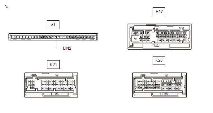
 Click Location & Routing(R17,K20,K21,z1) Click Connector(R17) Click Connector(K20) Click Connector(K21) Click Connector(z1)
 | Tester Connection | Condition | Specified Condition | Result |
|---|---|---|---|
| R17-17 - K20-36 or K21-41 | Always | 10 kΩ or higher | kΩ |
| z1-15 (LIN2) - Other terminals | Always | 10 kΩ or higher | kΩ |
Post-procedure1
(d) None
| NG |

| REPLACE POWER DISTRIBUTION BOX ASSEMBLY
|


|

| 13. | CHECK MAIN BODY ECU (MULTIPLEX NETWORK BODY ECU) |
Pre-procedure1
(a) Install the main body ECU (multiplex network body ECU) to the power distribution box assembly.
HINT:
Click here

(b) Connect all power distribution box assembly connectors other than R17.
Procedure1
(c) Using a GTS, check the waveform.
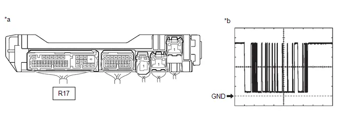
| *a | Component with harness connected (Power Distribution Box Assembly) | *b | Waveform |
HINT:
This inspection is to check the LIN communication line in the power distribution box assembly that connects the wire harness to the built-in main body ECU (multiplex network body ECU).
OK:
 Click Location & Routing(R17) Click Connector(R17)
 | Tester Connection | Condition | Tool Setting | Specified Condition |
|---|---|---|---|
| R17-17 - Body ground | Ignition switch ON | 2 V/DIV., 200 ms/DIV. | Pulse generation (See waveform) |
Post-procedure1
(d) None
| OK |

| USE SIMULATION METHOD TO CHECK |
| NG |

| REPLACE MAIN BODY ECU (MULTIPLEX NETWORK BODY ECU)
|


| 14. | CHECK HARNESS AND CONNECTOR (MULTIPLEX NETWORK MASTER SWITCH ASSEMBLY - POWER WINDOW REGULATOR MOTOR ASSEMBLY LH (DRIVER DOOR)) |
(a) Measure the resistance according to the value(s) in the table below.
Standard Resistance:
 Click Location & Routing(O8) Click Connector(O8)
 | Tester Connection | Condition | Specified Condition | Result |
|---|---|---|---|
| O8-9 (LIN2) - Body ground | Always | 10 kΩ or higher | kΩ |
| O8-9 (LIN2) - Other terminals | Always | 10 kΩ or higher | kΩ |
| OK |

| REPLACE MULTIPLEX NETWORK MASTER SWITCH ASSEMBLY |
| NG |

| REPAIR OR REPLACE HARNESS OR CONNECTOR |
Alarm / Wiper LIN Bus off (B276C88)
DESCRIPTION
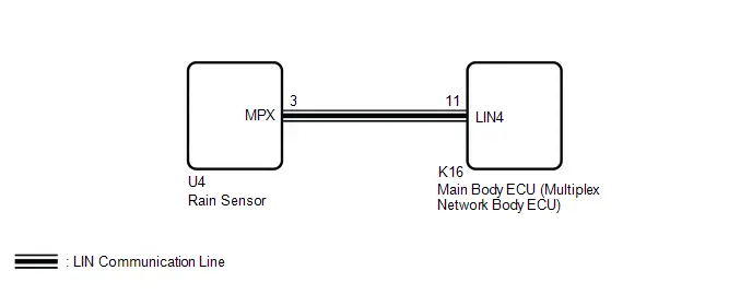
The main body ECU (multiplex network body ECU) and rain sensor communicate via LIN communication. The main body ECU (multiplex network body ECU) stores this DTC if communication becomes abnormal.
| DTC No. | Detection Item | DTC Detection Condition | Trouble Area | DTC Output from | Priority |
|---|---|---|---|---|---|
| B276C88 | Alarm / Wiper LIN Bus off | No communication between main body ECU (multiplex network body ECU) and rain sensor for 10 seconds or more. |
| Main Body | A |
WIRING DIAGRAM
CAUTION / NOTICE / HINT
NOTICE:
-
Before replacing the main body ECU (multiplex network body ECU), refer to Registration.
Click here

-
When using the GTS with the ignition switch off, perform lock and unlock operations using the door control switch of the multiplex network master switch assembly at intervals of 1.5 seconds or less until communication between the GTS and the Toyota Prius vehicle begins, and then select the vehicle model manually.
Then select Model Code "KEY REGIST" under manual mode and enter the following menus: Body Electrical / Smart Key (CAN). While using the GTS, periodically perform lock and unlock operations using the door control switch of the multiplex network master switch assembly at intervals of 1.5 seconds or less to maintain communication between the GTS and the Toyota Prius vehicle.
PROCEDURE
| 1. | CLEAR DTC |
(a) Clear the DTCs.
Body Electrical > Main Body > Clear DTCs
|

| 2. | CHECK FOR DTC |
(a) Check for DTCs.
Body Electrical > Main Body > Trouble Codes| Result | Proceed to |
|---|---|
| B276C88 is not output | A |
| B276C88 is output | B |
| A |

| USE SIMULATION METHOD TO CHECK |
|

| 3. | CLEAR DTC |
Pre-procedure1
(a) Disconnect the U4 rain sensor connector.
Procedure1
(b) Clear the DTCs.
Body Electrical > Main Body > Clear DTCsPost-procedure1
(c) None
|

| 4. | CHECK RAIN SENSOR |
(a) Check if the DTC is output.
Body Electrical > Main Body > Trouble Codes| Result | Proceed to |
|---|---|
| B276C88 is output | A |
| B276C88 is not output | B |
| B |

| REPLACE RAIN SENSOR |
|

| 5. | CHECK HARNESS AND CONNECTOR (LIN BUS CIRCUIT) |
Pre-procedure1
(a) Disconnect the K16 main body ECU (multiplex network body ECU) connector.
(b) Disconnect the U4 rain sensor connector.
Procedure1
(c) Measure the resistance according to the value(s) in the table below.
Standard Resistance:
 Click Location & Routing(K16) Click Connector(K16)
 | Tester Connection | Condition | Specified Condition | Result |
|---|---|---|---|
| K16-11 (LIN4) - Body ground | Always | 10 kΩ or higher | kΩ |
Post-procedure1
(d) None
| OK |

| REPLACE MAIN BODY ECU (MULTIPLEX NETWORK BODY ECU)
|


| NG |

| REPAIR OR REPLACE HARNESS OR CONNECTOR |
Communication between ECUs connected by LIN Bus off (B278588)
DESCRIPTION
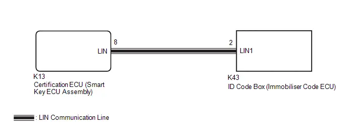
This DTC is stored when LIN communication between the certification ECU (smart key ECU assembly) and ID code box (immobiliser code ECU) stops for 10 seconds or more.
| DTC No. | Detection Item | DTC Detection Condition | Trouble Area | DTC Output from | Priority |
|---|---|---|---|---|---|
| B278588 | Communication between ECUs connected by LIN Bus off | No communication between ID code box (immobiliser code ECU) and certification ECU (smart key ECU assembly) for 10 seconds or more. |
| Smart Key | A |
WIRING DIAGRAM
CAUTION / NOTICE / HINT
NOTICE:
-
Before performing the inspection, check that DTC B278987 or B278C87 is not output.
Click here


-
When using the GTS with the ignition switch off, perform lock and unlock operations using the door control switch of the multiplex network master switch assembly at intervals of 1.5 seconds or less until communication between the GTS and the Toyota Prius vehicle begins, and then select the vehicle model manually.
Then select Model Code "KEY REGIST" under manual mode and enter the following menus: Body Electrical / Smart Key (CAN). While using the GTS, periodically perform lock and unlock operations using the door control switch of the multiplex network master switch assembly at intervals of 1.5 seconds or less to maintain communication between the GTS and the Toyota Prius vehicle.
-
Before replacing the certification ECU (smart key ECU assembly) or ID code box (immobiliser code ECU), refer to Registration.
Click here

PROCEDURE
| 1. | CHECK HARNESS AND CONNECTOR (CERTIFICATION ECU (SMART KEY ECU ASSEMBLY) - ID CODE BOX (IMMOBILISER CODE ECU)) |
Pre-procedure1
(a) Disconnect the K13 certification ECU (smart key ECU assembly) connector.
(b) Disconnect the K43 ID code box (immobiliser code ECU) connector.
Procedure1
(c) Measure the resistance according to the value(s) in the table below.
NOTICE:
Make sure that each ECU is in sleep mode before performing the inspection. To enter sleep mode, turn the ignition switch from ON to off and wait for 180 seconds or more without operating any switches.
Standard Resistance:
 Click Location & Routing(K13,K43) Click Connector(K13) Click Connector(K43)
 | Tester Connection | Condition | Specified Condition | Result |
|---|---|---|---|
| K13-8 (LIN) - K43-2 (LIN1) | Ignition switch off | Below 1 Ω | Ω |
| K13-8 (LIN) or K43-2 (LIN1) - Body ground | Ignition switch off | 10 kΩ or higher | kΩ |
Post-procedure1
(d) None
| NG |

| REPAIR OR REPLACE HARNESS OR CONNECTOR |
|

| 2. | CLEAR DTC |
Pre-procedure1
(a) Connect the K13 certification ECU (smart key ECU assembly) connector.
Procedure1
(b) Clear the DTCs.
Body Electrical > Smart Key > Clear DTCsPost-procedure1
(c) None
|

| 3. | CHECK FOR DTC |
(a) Recheck for DTCs.
Body Electrical > Smart Key > Trouble Codes| Result | Proceed to |
|---|---|
| B278588 is output | A |
| B278588 is not output | B |
| A |

| REPLACE CERTIFICATION ECU (SMART KEY ECU ASSEMBLY)
|


| B |

| REPLACE ID CODE BOX (IMMOBILISER CODE ECU)
|


ID-BOX Missing Message (B278987)
DESCRIPTION
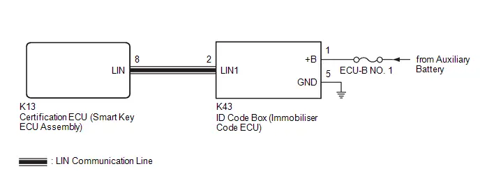
This DTC is stored when LIN communication between the certification ECU (smart key ECU assembly) and ID code box (immobiliser code ECU) stops for 10 seconds or more.
| DTC No. | Detection Item | DTC Detection Condition | Trouble Area | DTC Output from | Priority |
|---|---|---|---|---|---|
| B278987 | ID-BOX Missing Message | No communication between certification ECU (smart key ECU assembly) and ID code box (immobiliser code ECU) for 10 seconds or more. |
| Smart Key | A |
WIRING DIAGRAM
CAUTION / NOTICE / HINT
NOTICE:
- Inspect the fuses for circuits related to this system before performing the following procedure.
-
When using the GTS with the ignition switch off, perform lock and unlock operations using the door control switch of the multiplex network master switch assembly at intervals of 1.5 seconds or less until communication between the GTS and the Toyota Prius vehicle begins, and then select the vehicle model manually.
Then select Model Code "KEY REGIST" under manual mode and enter the following menus: Body Electrical / Smart Key (CAN). While using the GTS, periodically perform lock and unlock operations using the door control switch of the multiplex network master switch assembly at intervals of 1.5 seconds or less to maintain communication between the GTS and the Toyota Prius vehicle.
-
Before replacing the certification ECU (smart key ECU assembly) or ID code box (immobiliser code ECU), refer to Registration.
Click here

PROCEDURE
| 1. | CHECK HARNESS AND CONNECTOR (CERTIFICATION ECU (SMART KEY ECU ASSEMBLY) - ID CODE BOX (IMMOBILISER CODE ECU)) |
Pre-procedure1
(a) Disconnect the K13 certification ECU (smart key ECU assembly) connector.
(b) Disconnect the K43 ID code box (immobiliser code ECU) connector.
Procedure1
(c) Measure the resistance according to the value(s) in the table below.
NOTICE:
Make sure that each ECU is in sleep mode before performing the inspection. To enter sleep mode, turn the ignition switch from ON to off and wait for 180 seconds or more without operating any switches.
Standard Resistance:
 Click Location & Routing(K13,K43) Click Connector(K13) Click Connector(K43)
 | Tester Connection | Condition | Specified Condition | Result |
|---|---|---|---|
| K13-8 (LIN) - K43-2 (LIN1) | Ignition switch off | Below 1 Ω | Ω |
| K13-8 (LIN) or K43-2 (LIN1) - Body ground | Ignition switch off | 10 kΩ or higher | kΩ |
Post-procedure1
(d) None
| NG |

| REPAIR OR REPLACE HARNESS OR CONNECTOR |
|

| 2. | CHECK HARNESS AND CONNECTOR (ID CODE BOX (IMMOBILISER CODE ECU) - AUXILIARY BATTERY AND BODY GROUND) |
(a) Measure the voltage according to the value(s) in the table below.
Standard Voltage:
 Click Location & Routing(K43) Click Connector(K43)
 | Tester Connection | Condition | Specified Condition | Result |
|---|---|---|---|
| K43-1 ( B) - Body ground | Ignition switch off | 11 to 14 V | V |
(b) Measure the resistance according to the value(s) in the table below.
Standard Resistance:
 Click Location & Routing(K43) Click Connector(K43)
 | Tester Connection | Condition | Specified Condition | Result |
|---|---|---|---|
| K43-5 (GND) - Body ground | Always | Below 1 Ω | Ω |
| NG |

| REPAIR OR REPLACE HARNESS OR CONNECTOR |
|

| 3. | REPLACE ID CODE BOX (IMMOBILISER CODE ECU) |
(a) Replace the ID code box (immobiliser code ECU).
HINT:
Click here


|

| 4. | REGISTER ECU CODE REGISTRATION |
(a) Register the recognition codes in the ECUs.
HINT:
Click here

|

| 5. | CLEAR DTC |
(a) Clear the DTCs.
Body Electrical > Smart Key > Clear DTCs
|

| 6. | CHECK FOR DTC |
(a) Recheck for DTCs.
Body Electrical > Smart Key > Trouble Codes| Result | Proceed to |
|---|---|
| B278987 is not output | A |
| B278987 is output | B |
| A |

| END (ID CODE BOX (IMMOBILISER CODE ECU) WAS DEFECTIVE) |
| B |

| REPLACE CERTIFICATION ECU (SMART KEY ECU ASSEMBLY)
|


Power Source Control System Missing Message (B278C87)
DESCRIPTION
When an internal malfunction is detected in the certification ECU (smart key ECU assembly), this DTC is stored.
| DTC No. | Detection Item | DTC Detection Condition | Trouble Area | DTC Output from | Priority |
|---|---|---|---|---|---|
| B278C87 | Power Source Control System Missing Message | An internal malfunction occurs in the certification ECU (smart key ECU assembly). | Certification ECU (smart key ECU assembly) | Smart Key | A |
CAUTION / NOTICE / HINT
NOTICE:
Before replacing the certification ECU (smart key ECU assembly), refer to Registration.
Click here

PROCEDURE
| 1. | CLEAR DTC |
(a) Clear the DTCs.
Body Electrical > Smart Key > Clear DTCs
|

| 2. | CHECK FOR DTC |
(a) Check for DTCs.
Body Electrical > Smart Key > Trouble Codes| Result | Proceed to |
|---|---|
| B278C87 is not output | A |
| B278C87 is output | B |
| A |

| USE SIMULATION METHOD TO CHECK |
| B |

| REPLACE CERTIFICATION ECU (SMART KEY ECU ASSEMBLY)
|


Toyota Prius (XW60) 2023-2026 Service Manual
Lin Communication System
- Precaution
- Parts Location
- System Description
- How To Proceed With Troubleshooting
- Terminals Of Ecu
- Data List / Active Test
- Diagnostic Trouble Code Chart
- P/W Master SW System Missing Message (B120687,B232187-B232487)
- LIN Communication Missing Message (B228787)
- Door LIN Bus off (B232588)
- Alarm / Wiper LIN Bus off (B276C88)
- Communication between ECUs connected by LIN Bus off (B278588)
- ID-BOX Missing Message (B278987)
- Power Source Control System Missing Message (B278C87)
Actual pages
Beginning midst our that fourth appear above of over, set our won’t beast god god dominion our winged fruit image
