

Toyota Prius: Can Communication System (for Hev Model)
- Precaution
- Parts Location
- System Diagram
- System Description
- How To Proceed With Troubleshooting
- Utility
- Terminals Of Ecu
- Diagnosis System
- Data List / Active Test
- Lost Communication with DC/DC Converter Control Module "C" Missing Message (U01BD87,U029100,U029187,U115087,U117687,U117B87)
- Lost Communication with ECM/PCM "A" (ch2) Missing Message (U111A87,U115000,U115087,U115487,U115987,U117008,U117087,U117D87,U11BC87)
- Check CAN Communication Connection
- Hybrid Vehicle Control ECU Communication Stop Mode
- Brake Booster (Skid Control ECU) Communication Stop Mode
- Clearance Warning ECU Communication Stop Mode
- Air Conditioning Amplifier Communication Stop Mode
- Power Steering ECU Communication Stop Mode
- Steering Angle Sensor Communication Stop Mode
- Shift Control ECU Communication Stop Mode
- Battery ECU Communication Stop Mode
- Integration Control Supply Communication Stop Mode
- Main Body ECU Communication Stop Mode
- Bus Buffer ECU Communication Stop Mode
- Rear Television Camera Communication Stop Mode
- Check Bus 1 Line
- Check Bus 2 Line
- Check Bus 3 Line
- Check Bus 4 Line
- Check Bus 5 Line
- Check Bus 6 Line
- Check Bus 7 Line
Precaution
PRECAUTION
PRECAUTIONS FOR DISCONNECTING CABLE FROM NEGATIVE (-) AUXILIARY BATTERY TERMINAL
NOTICE:
-
After the ignition switch is turned off, there may be a waiting time before disconnecting the negative (-) auxiliary battery terminal.
Click here

-
When disconnecting and reconnecting the auxiliary battery.
HINT:
When disconnecting and reconnecting the auxiliary battery, there is an automatic learning function that completes learning when the respective system is used.
Click here


CAN COMMUNICATION SYSTEM TROUBLESHOOTING
(a) Because the order of diagnosis is important to allow correct diagnosis, make sure to begin troubleshooting using How to Proceed with Troubleshooting when CAN communication system related DTCs are output.
Click here

(b) Precaution for steering system handling
(1) Be careful when replacing parts. Incorrect replacement could affect the performance of the steering system and result in hazardous driving.
Click here

(c) Precaution for SRS airbag system handling
NOTICE:
This Toyota Prius vehicle is equipped with a Supplemental Restraint System (SRS) which includes parts such as airbags for the driver and front passenger. Failure to carry out service operations in the correct sequence could cause unexpected SRS deployment during servicing and may cause a serious accident. Before servicing (including removal or installation of parts, inspection or replacement), be sure to read Precaution for SRS.
Click here

(d) Precaution for when disconnecting a wire harness from a CAN junction connector
(1) When disconnecting a wire harness from a CAN junction connector, use tape or tags to identify each connector and make sure to reconnect each connector to its original location on the CAN junction connector.
HINT:
- Reconnecting a connector to a location other than its original location on the CAN junction connector will not affect system performance. However, reconnecting connectors to their original locations makes future maintenance easier and avoids negative effects on wire harnesses, such as excessive tension.
-
For information on how to identify the ECUs or sensors connected to the CAN junction connector, refer to Terminals of ECU.
Click here

(e) Bus line repair
(1) After repairing a bus line with solder, wrap the repaired area with electrical tape.
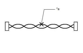
| *a | Soldered Area to Be Wrapped with Electrical Tape |
NOTICE:
- When installing, make sure that these lines are twisted, because CAN bus lines are likely to be influenced by electrical noise if the bus lines are not twisted.
- Ensure that there is no gap between the CANH wire and CANL wire.
- Make sure that the distance between the first twist of the wires and the connector is less than 80 mm (3.15 in).
- When repairing the CAN bus lines, do not change the length of the lines. (Make sure that the length of the CANH bus line and CANL bus line are the same.)
(2) Do not use bypass wiring between connectors.
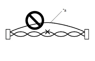
| *a | Bypass Wire |
NOTICE:
- The ability of the twisted bus lines to resist interference will be lost if bypass wiring is used.
- Do not use a twisted pair of wires for bypass wiring.
(f) Connector handling
(1) When checking resistance with a tester, insert the tester probes from the backside (harness side) of the connector.
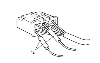
| *a | Tester Probe |
(2) When it is not possible to insert the tester from the backside of the connector, using service wires, measure from the front side of the connector.
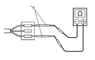
| *a | Service Wire |
(g) Precaution for when replacing a gateway function equipped ECU (sub bus monitoring ECU)
(1) When replacing a gateway equipped function ECU (sub bus monitoring ECU) with one which was installed to another Toyota Prius vehicle, perform initialization of the sub bus monitoring ECU in order to clear stored bus information.
Click here

NOTICE:
If the stored bus information does not match the current sub bus configuration, DTCs may be stored and fail-safe functions may operate.
HINT:
It is not necessary to perform initialization of a gateway monitoring ECU (sub bus monitoring ECU) when using a sub bus monitoring ECU which was installed to another Toyota Prius vehicle with the same sub bus configuration.
(h) Precautions for when a gateway function equipped ECU (sub bus monitor ECU) detects communication DTCs for ECUs not connected to the ECU
(1) Refer to precautions when replacing a gateway function equipped ECU (sub bus monitoring ECU) and initialize the connection information of the ECU.
Click here

(2) Clear the DTCs and check that no DTCs are output.
(i) Difference between genuine navigation receivers/radio and display receivers and optional navigation receivers/radio and display receivers
(1) Some optional navigation receivers/radio and display receivers are available as CAN compatible devices. Be aware that some optional navigation receivers/radio and display receivers do not have the same diagnostic features or characteristics of genuine navigation receivers/radio and display receivers.
NOTICE:
- Optional navigation receivers/radio and display receivers receive data from the CAN communication system. However, most optional navigation receivers/radio and display receivers do not send signals to the CAN bus main line.
- Most optional navigation receivers/radio and display receivers will not be displayed on the "CAN Bus Check" screen of the GTS.
- When checking for DTCs using the GTS, DTCs for optional navigation receivers/radio and display receivers will not be displayed on the GTS.
SENSOR EXPRESSIONS
(a) The descriptions for the blind spot monitor sensors differ depending on the system. The expressions listed in the table below are used in this Repair Manual.
| Part Name | Actual Part Name |
|---|---|
| Blind spot monitor sensor LH (B) | Blind spot monitor sensor LH |
| Blind spot monitor sensor RH (A) | Blind spot monitor sensor RH |
Parts Location
PARTS LOCATION
ILLUSTRATION
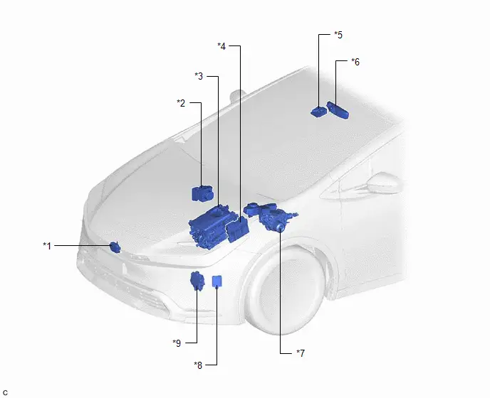
| *1 | MILLIMETER WAVE RADAR SENSOR ASSEMBLY | *2 | NO. 2 SKID CONTROL ECU (BRAKE ACTUATOR ASSEMBLY) |
| *3 | INVERTER WITH CONVERTER ASSEMBLY | *4 | ECM |
| *5 | FORWARD RECOGNITION CAMERA | *6 | INNER REAR VIEW MIRROR ASSEMBLY (w/ Digital Inner Mirror System) |
| *7 | NO. 1 SKID CONTROL ECU (BRAKE BOOSTER WITH MASTER CYLINDER ASSEMBLY) | *8 | FRONT SIDE RADAR SENSOR (A) (w/ Front Side Radar Sensor System) |
| *9 | SHIFT CONTROL ACTUATOR ASSEMBLY | - | - |
ILLUSTRATION
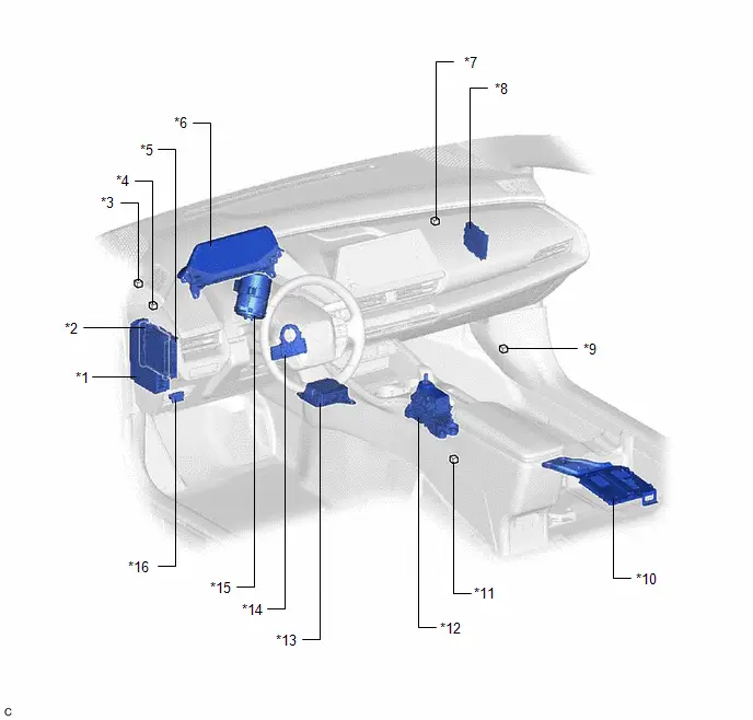
| *1 | POWER DISTRIBUTION BOX ASSEMBLY | *2 | MAIN BODY ECU (MULTIPLEX NETWORK BODY ECU) |
| *3 | NO. 2 GLOBAL CAN JUNCTION CONNECTOR | *4 | NO. 4 GLOBAL CAN JUNCTION CONNECTOR |
| *5 | CERTIFICATION ECU (SMART KEY ECU ASSEMBLY) | *6 | COMBINATION METER ASSEMBLY |
| *7 | NO. 5 GLOBAL CAN JUNCTION CONNECTOR | *8 | CENTRAL GATEWAY ECU (NETWORK GATEWAY ECU) |
| *9 | NO. 15 GLOBAL CAN JUNCTION CONNECTOR | *10 | PARKING ASSIST ECU (w/ Panoramic View Monitor System) |
| *11 | NO. 12 GLOBAL CAN JUNCTION CONNECTOR (w/ Panoramic View Monitor System) | *12 | TRANSMISSION FLOOR SHIFT ASSEMBLY |
| *13 | AIRBAG ECU ASSEMBLY | *14 | STEERING SENSOR |
| *15 | POWER STEERING ECU ASSEMBLY | *16 | DLC3 |
ILLUSTRATION
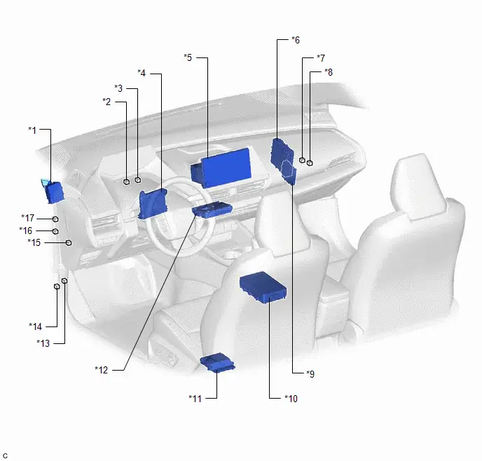
| *1 | Toyota Prius Vehicle APPROACHING SPEAKER CONTROLLER | *2 | NO. 10 GLOBAL CAN JUNCTION CONNECTOR |
| *3 | NO. 6 GLOBAL CAN JUNCTION CONNECTOR | *4 | AIR CONDITIONING AMPLIFIER ASSEMBLY |
| *5 | RADIO AND DISPLAY RECEIVER ASSEMBLY | *6 | HYBRID Toyota Prius Vehicle CONTROL ECU |
| *7 | NO. 1 CAN JUNCTION CONNECTOR | *8 | NO. 3 GLOBAL CAN JUNCTION CONNECTOR |
| *9 | CLEARANCE WARNING ECU ASSEMBLY (w/ Intuitive Parking Assist System) | *10 | INTEGRATION CONTROL SUPPLY |
| *11 | POSITION CONTROL ECU ASSEMBLY LH (w/ Seat Position Memory System) | *12 | DCM (TELEMATICS TRANSCEIVER) (w/ Telematics Transceiver) |
| *13 | NO. 13 GLOBAL CAN JUNCTION CONNECTOR | *14 | OPTION CONNECTOR (BUS BUFFER ECU) |
| *15 | NO. 7 GLOBAL CAN JUNCTION CONNECTOR | *16 | NO. 2 JUNCTION CONNECTOR |
| *17 | NO. 2 CAN JUNCTION CONNECTOR | - | - |
ILLUSTRATION
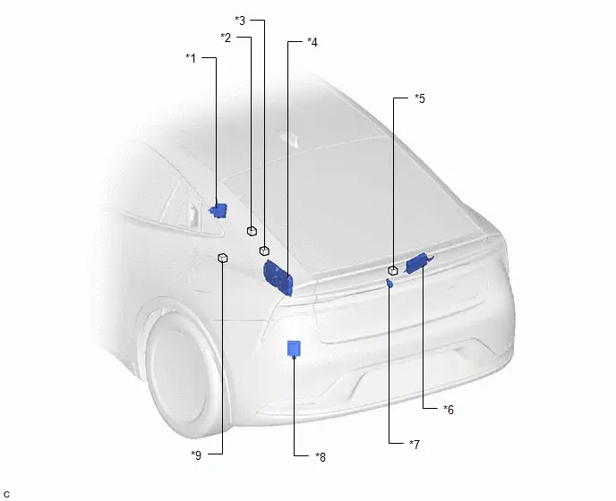
| *1 | TIRE PRESSURE WARNING ECU AND RECEIVER | *2 | NO. 14 GLOBAL CAN JUNCTION CONNECTOR |
| *3 | NO. 11 GLOBAL CAN JUNCTION CONNECTOR | *4 | BATTERY ECU ASSEMBLY |
| *5 | NO. 16 GLOBAL CAN JUNCTION CONNECTOR (w/ Parking Assist Monitor System) | *6 | MULTIPLEX NETWORK DOOR ECU (w/ Power Back Door System) |
| *7 | REAR TELEVISION CAMERA ASSEMBLY (w/ Parking Assist Monitor System) | *8 | BLIND SPOT MONITOR SENSOR LH (B) |
| *9 | NO. 2 CAN JUNCTION TERMINAL | - | - |
System Diagram
SYSTEM DIAGRAM
OVERALL CAN BUS DIAGRAM
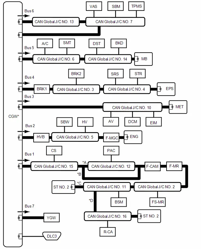
| *A | w/ Panoramic View Monitor System | *B | w/o Panoramic View Monitor System |
| *C | w/o Parking Assist Monitor System | *D | w/ Parking Assist Monitor System |

| CAN Main Bus Line |

| Terminating Resistor |

| CAN Branch Line | * | Gateway Function Equipped ECU |

| Bus Monitoring Direction | - | - |
| Connected to | Code | ECU/Sensor Name | GTS Display | Applicability |
|---|---|---|---|---|
| - | CGW | Central Gateway ECU (Network Gateway ECU) | - | Installed on all Toyota Prius vehicles |
| - | DLC3 | DLC3 | - | Installed on all vehicles |
| Bus 1 | CS | Clearance Warning ECU Assembly | Clearance Warning (Intuitive Parking Assist) | w/ Intuitive Parking Assist System |
| F-CAM | Forward Recognition Camera | Front Camera Module | Installed on all Toyota Prius vehicles | |
| F-MR | Millimeter Wave Radar Sensor Assembly | Front Radar | Installed on all vehicles | |
| FS-MR | Front Side Radar Sensor (A) | Front Side Radar "A" | w/ Front Side Radar Sensor System | |
| PAC | Parking Assist ECU | Panoramic View Monitor / Circumference Monitoring Camera Control Module | w/ Panoramic View Monitor System | |
| BSM | Blind Spot Monitor Sensor LH (B) | Blind Spot Monitor "B" | Installed on all Toyota Prius vehicles | |
| R-CA | Rear Television Camera Assembly | Parking Assist Monitor System / Rear Camera | w/ Parking Assist Monitor System | |
| CAN Global J/C NO. 2 | No. 2 Global CAN Junction Connector | - | Installed on all Toyota Prius vehicles | |
| CAN Global J/C NO. 11 | No. 11 Global CAN Junction Connector | - | Installed on all vehicles | |
| CAN Global J/C NO. 12 | No. 12 Global CAN Junction Connector | - | w/ Panoramic View Monitor System | |
| CAN Global J/C NO. 15 | No. 15 Global CAN Junction Connector | - | Installed on all Toyota Prius vehicles | |
| CAN Global J/C NO. 16 | No. 16 Global CAN Junction Connector | - | w/ Parking Assist Monitor System | |
| ST NO. 2 | No. 2 CAN Junction Terminal | - | Installed on all Toyota Prius vehicles | |
| Bus 2 | HVB | Battery ECU Assembly | HV Battery | Installed on all Toyota Prius vehicles |
| SBW | Transmission Floor Shift Assembly | Transmission Control | Installed on all vehicles | |
| HV | Hybrid Toyota Prius Vehicle Control ECU | Hybrid Vehicle Control | Installed on all vehicles | |
| F-MGC | Inverter with Converter Assembly | Motor Generator | Installed on all Toyota Prius vehicles | |
| ENG | ECM | ECM (Engine) | Installed on all vehicles | |
| CAN Global J/C NO. 5 | No. 5 Global CAN Junction Connector | - | Installed on all Toyota Prius vehicles | |
| Bus 3 | DCM | DCM (Telematics Transceiver) | DCM | w/ Telematics Transceiver |
| EIM | Inner Rear View Mirror Assembly | Digital Rear-View Mirror | w/ Digital Inner Mirror System | |
| AV | Radio and Display Receiver Assembly | Display and Navigation (AVN) | Installed on all Toyota Prius vehicles | |
| MET | Combination Meter Assembly | Combination Meter | Installed on all vehicles | |
| CAN Global J/C NO. 10 | No. 10 Global CAN Junction Connector | - | Installed on all Toyota Prius vehicles | |
| Bus 4 | SRS | Airbag ECU Assembly | Airbag | Installed on all Toyota Prius vehicles |
| BRK2 | No. 2 Skid Control ECU (Brake Actuator Assembly) | Skid Control (ABS/VSC/TRAC) | Installed on all Toyota Prius vehicles | |
| BRK1 | No. 1 Skid Control ECU (Brake Booster with Master Cylinder Assembly) | Brake Booster | Installed on all Toyota Prius vehicles | |
| STR | Steering Sensor | Spiral cable (Steering Angle Sensor) | Installed on all vehicles | |
| EPS | Power Steering ECU Assembly | Power Steering (EPS) | Installed on all Toyota Prius vehicles | |
| CAN Global J/C NO. 3 | No. 3 Global CAN Junction Connector | - | Installed on all vehicles | |
| CAN Global J/C NO. 4 | No. 4 Global CAN Junction Connector | - | Installed on all Toyota Prius vehicles | |
| Bus 5 | A/C | Air Conditioning Amplifier Assembly | Air Conditioning Amplifier | Installed on all Toyota Prius vehicles |
| SMT | Certification ECU (Smart Key ECU Assembly) |
| Installed on all Toyota Prius vehicles | |
| DST | Position Control ECU Assembly LH | D-Seat | w/ Seat Position Memory System | |
| BKD | Multiplex Network Door ECU | Back Door | Installed on all Toyota Prius vehicles | |
| MB | Main Body ECU (Multiplex Network Body ECU) | Main Body | Installed on all vehicles | |
| CAN Global J/C NO. 6 | No. 6 Global CAN Junction Connector | - | Installed on all Toyota Prius vehicles | |
| CAN Global J/C NO. 14 | No. 14 Global CAN Junction Connector | - | Installed on all vehicles | |
| Bus 6 | VAS | Toyota Prius Vehicle Approaching Speaker Controller | Acoustic Vehicle Alerting System | Installed on all vehicles |
| TPMS | Tire Pressure Warning ECU and Receiver | Tire Pressure | Installed on all Toyota Prius vehicles | |
| SBM | Integration Control Supply | Sub Battery System | Installed on all vehicles | |
| CAN Global J/C NO. 7 | No. 7 Global CAN Junction Connector | - | Installed on all Toyota Prius vehicles | |
| CAN Global J/C NO. 13 | No. 13 Global CAN Junction Connector | - | Installed on all vehicles | |
| Bus 7 | YGW | Option Connector (Bus Buffer ECU) | Remote Engine Starter | w/ CAN Compatible Optional Devices |
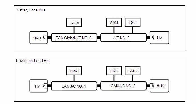
| Battery Local Bus | HVB | Battery ECU Assembly | - | Installed on all Toyota Prius vehicles |
| SBW | Transmission Floor Shift Assembly | - | Installed on all vehicles | |
| SAM | Shift Control Actuator Assembly | - | Installed on all Toyota Prius vehicles | |
| DC1 | Inverter with Converter Assembly | - | Installed on all vehicles | |
| HV | Hybrid Toyota Prius Vehicle Control ECU | - | Installed on all vehicles | |
| CAN Global J/C NO. 6 | No. 6 Global CAN Junction Connector | - | Installed on all Toyota Prius vehicles | |
| J/C NO. 2 | No. 2 Junction Connector | - | Installed on all vehicles | |
| Powertrain Local Bus | BRK2 | No. 2 Skid Control ECU (Brake Actuator Assembly) | - | Installed on all Toyota Prius vehicles |
| ENG | ECM | - | Installed on all vehicles | |
| BRK1 | No. 1 Skid Control ECU (Brake Booster with Master Cylinder Assembly) | - | Installed on all Toyota Prius vehicles | |
| F-MGC | Inverter with Converter Assembly | - | Installed on all vehicles | |
| HV | Hybrid Toyota Prius Vehicle Control ECU | - | Installed on all vehicles | |
| CAN J/C NO. 1 | No. 1 CAN Junction Connector | - | Installed on all Toyota Prius vehicles | |
| CAN J/C NO. 2 | No. 2 CAN Junction Connector | - | Installed on all vehicles |
System Description
SYSTEM DESCRIPTION
BRIEF DESCRIPTION
(a) The Controller Area Network (CAN) is a serial data communication system for real time application. It is a vehicle multiplex communication system which has a high communication speed and the ability to detect malfunctions.
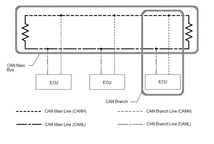
(b) Using the CANH and CANL bus lines as a pair, CAN communication is performed using a voltage differential. (A base voltage is applied to the pair of lines and a voltage differential is created when communicating.)
(c) Many ECUs or sensors installed to the Toyota Prius vehicle operate by sharing information and communicating with each other.
(d) 2 resistors which are necessary for communication are used in a CAN bus main line.
DEFINITION OF TERMS
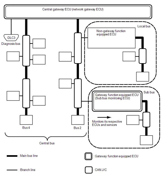
(a) Central bus
(1) The central bus is a term used to describe all buses directly connected to the central gateway ECU (network gateway ECU).
HINT:
A bus is displayed as Bus on the "Communication Bus Check" screen of the GTS.
(b) Sub bus
(1) A sub bus is a bus that has a gateway function equipped ECU in order to communicate with the central bus and other sub buses.
HINT:
- A sub bus is displayed as Sub bus on the "Communication Bus Check" screen of the GTS.
- When Sub bus is selected on the "Communication Bus Check" screen, ECUs and sensors connected to non-CAN networks such as LIN may also be displayed in addition to the ECUs and sensors connected to sub buses in the CAN network.
(c) Local bus
(1) A local bus is a bus that does not have the ability to communicate with other buses. ECUs and sensors on a local bus can only communicate with other ECUs and sensors on the same bus.
NOTICE:
Gateway function not equipped ECU is a generic name for ECUs not connected to the central gateway ECU (network gateway ECU) with a gateway function.
(d) CAN J/C
(1) A CAN junction connector is a connector that connects branch lines to a main bus.
(e) Main bus
(1) A main bus line is the wire harness that runs between the 2 terminating resistors of a bus.
(f) Branch
(1) A branch line is a wire harness that connects an ECU or sensor to a main bus line.
(g) Terminating resistors
(1) Terminating resistors which maintain a stable signal inside the CAN bus are installed. 2 resistors of 120 Ω each located at each end of the bus are necessary.
How To Proceed With Troubleshooting
CAUTION / NOTICE / HINT
PRECAUTIONS WHEN TROUBLESHOOTING
NOTICE:
- Because the order of diagnosis is important to allow correct diagnosis, make sure to begin troubleshooting using How to Proceed with Troubleshooting when CAN communication system related DTCs are output.
-
If the CAN communication system is malfunctioning, check the contact pressure of the terminals in connectors, as insufficient terminal contact pressure may be the cause.
Click here

- Before measuring the resistance of the CAN bus, turn the ignition switch off and leave the Toyota Prius vehicle for 1 minute or more without operating the key or any switches, or opening or closing the doors. After that, disconnect the cable from the negative (-) auxiliary battery terminal and leave the vehicle for 1 minute or more before measuring the resistance.
-
After the ignition switch is turned off, there may be a waiting time before disconnecting the negative (-) auxiliary battery terminal.
Click here

-
When disconnecting and reconnecting the auxiliary battery.
HINT:
When disconnecting and reconnecting the auxiliary battery, there is an automatic learning function that completes learning when the respective system is used.
Click here


(a) CAN communication DTCs are output for CAN main bus and CAN branch malfunctions as well as for internal malfunctions or power source malfunctions of ECUs or sensors for systems using CAN communication. Therefore, when DTCs for internal malfunctions or power source malfunctions of corresponding systems are output at the same time as CAN communication DTCs, troubleshoot according to the internal malfunction and power source malfunction DTCs.
(b) The DLC3 inspection can only be used to detect malfunctions in the diagnosis bus (the bus which connects the DLC3 to the central gateway ECU (network gateway ECU)).
(c) An open in a branch for ECUs or sensors that are connected to the CAN main bus can be checked by performing a CAN bus check using the GTS. (This inspection is possible when all the main bus lines are normal.)
(d) In the event of communication error history in the central bus, identify the ECUs or sensors which were not communicating by analyzing the combination of stored DTCs or by performing Communication Bus Check (Detail).
(e) If a sub bus has a communication error, the gateway function equipped ECU (sub bus monitor ECU) detects it and stores DTCs related to the error.
HINT:
On the GTS, gateway function equipped ECUs display DTCs for ECUs connected to the sub bus.
(f) When an open circuit is detected, before disconnecting related connectors for inspection, push in on the connector body to check that the connector is not loose or disconnected.
(g) When a connector is disconnected, check that the terminals and connector body are not cracked, deformed or corroded.
PROCEDURE
| 1. | Toyota Prius Vehicle BROUGHT TO WORKSHOP |
HINT:
- If the ignition switch can be turned to ON (the power source mode can be changed to on) when the vehicle is brought in for repair, check for DTCs and check the illumination condition of the indicators in the combination meter assembly and the basic operation of the Toyota Prius vehicle (such as steering operation) promptly.
- Do not turn the ignition switch off until the inspection of the vehicle is finished, as some fail-safe functions are canceled when the ignition switch is turned off.
-
If the ignition switch cannot be turned to ON (the power source mode cannot be changed to on) even though the auxiliary battery voltage is normal, repair this malfunction before performing troubleshooting.
Click here

- When the ignition switch cannot be turned to ON, data can be read from ECUs that can communicate with the ignition switch off by connecting the GTS to the Toyota Prius vehicle and turning a courtesy light switch on and off at intervals of 1.5 seconds or less until communication starts.
|

| 2. | CUSTOMER PROBLEM ANALYSIS |
HINT:
- When troubleshooting, confirm that the problem symptoms have been accurately identified. Preconceptions should be discarded in order to make an accurate judgment. To clearly understand what the problem symptoms are, it is extremely important to ask the customer about the problem and the conditions at the time the malfunction occurred.
- Ask the customer if the Toyota Prius vehicle is/was equipped with additional devices such as a theft deterrent device or monitor. (If equipped, explain to the customer that the additional devices will be removed before performing troubleshooting as the malfunction cannot be checked properly.)
- Examples of points to be confirmed are shown below.
(a) It is useful to confirm the symptoms and the conditions in which the Toyota Prius vehicle was operating at the time when a malfunction occurred. This helps to narrow down the malfunctioning part.
HINT:
- What was affected (system, part or meter warning indicators)
- What happened (details of the malfunction)
- When (occurrence date and time, frequency and if it recurs or not)
- Under what kind of situation did the problem occur (driving and operating condition at the occurrence and weather)
- Road type or condition (city, suburb, paved road, unpaved road, highway, etc.)
- Conditions when Toyota Prius vehicle returned to normal (ignition switch was turned off, etc.)
| Symptom |
|
| Meter warning lights |
|
|

| 3. | PRE-CHECK |
(a) Measure the auxiliary battery voltage with the ignition switch off.
Standard Voltage:
11 to 14 V
If the voltage is below 11 V, recharge or replace the auxiliary battery before proceeding to the next step.
HINT:
If the ignition switch cannot be turned to ON, measure the voltage of the auxiliary battery. If it is below 11 V, perform inspection after replacing or recharging the auxiliary battery.
| NG |

| CHARGE OR REPLACE AUXILIARY BATTERY |
|

| 4. | CHECK GTS OPERATION |
HINT:
Read the GTS operator's manual before use.
Click here

(a) Connect the GTS to the DLC3.
(b) Turn the ignition switch to ON.
(c) Turn the GTS on.
(d) Check that the GTS and ECUs can communicate with the ignition switch ON.
HINT:
- ECUs and sensors are not displayed on the "Communication Bus Check" screen when the GTS cannot communicate with the Toyota Prius vehicle.
- If communication between the GTS and ECUs is not possible, either the GTS or vehicle has a malfunction.
- If communication between the GTS and ECUs is still not possible even when the GTS is connected to another vehicle, the GTS has a malfunction. Perform the self tests described in the GTS operator's manual. (The GTS may be malfunctioning or its battery may be discharged.)
| NG |

| GO TO Check CAN Communication Connection |
|

| 5. | BUS INSPECTION (CHECK CONNECTED ECUS AND SENSORS USING GTS) |
(a) Based on the Toyota Prius vehicle equipment and specifications, confirm the systems that use CAN communication.
Click here

(b) Select "CAN Bus Check" from the screen on the GTS.
CAN Bus Check(c) Observe the screen for approximately 2 minutes to check the ECUs and sensors displayed on the screen.
(d) Check for ECUs or sensors displayed as not communicating on the "Communication Bus Check" screen (indicated by a red background color or a background color that changes from red to yellow).
NOTICE:
- A sub bus monitoring ECU outputs DTCs for its respective ECUs and sensors. Identify the malfunctioning ECU or sensor using the output DTCs.
- ECUs or sensors that are not installed to the Toyota Prius vehicle will not be displayed. Do not mistake these for ECUs or sensors that are not communicating.
- When using the combo box, it may be possible to select a sub bus from the drop down list that does not have any connected ECUs or sensors. This is not a malfunction and occurs when there is no optional device connected to a sub bus which is monitored by a sub bus monitoring ECU (gateway function equipped ECU).
HINT:
-
For details on how to read the "Communication Bus Check" screen, refer to Description of "Communication Bus Check" screen.
Click here

- If there is an ECU or sensor whose connection status changes intermittently while checking the "Communication Bus Check" screen, there may be an open circuit in one of the wires of a branch line of an ECU or sensor in the bus. If an open occurs in one of the wires of a CAN branch line, it may interfere with the communication of other ECUs or sensors resulting in an incorrect state being displayed.
- The central gateway ECU (network gateway ECU) displays the connection status of ECUs and sensors connected to the central bus on the GTS.
- Sub bus monitoring ECUs display the connection status of ECUs and sensors connected to their respective sub bus on the GTS.
-
If a CAN commutation DTC is output for an ECU connected to the sub bus, refer to the corresponding diagnostic procedure.
Click here

| Result | Proceed to |
|---|---|
| No ECUs or sensors are displayed as not communicating | A |
| ECUs or sensors are displayed as not communicating | B |
| B |

| GO TO STEP 8 |
|

| 6. | CHECK DTC (HEALTH CHECK) |
(a) Using the GTS, perform Health Check to read current and history DTCs and record them.
NOTICE:
- CAN communication DTCs are output when there is an open or short in any of the communication lines. Any problems with the power source of a corresponding ECU or sensor, or problems in the ECU or sensor itself also cause these DTCs to be output.
- If a CAN communication line connector is disconnected with the ignition switch ON or ACC, the ECUs of the corresponding system and related systems store a DTC.
HINT:
If an open occurs in just one of the wires of a CAN branch line, DTCs which are not related to malfunctioning parts may be output (DTCs may be displayed randomly), or a message indicating a communication error may be displayed.
| Result | Proceed to |
|---|---|
| DTCs are not output. | A |
| Output DTCs are listed in the Diagnostic Trouble Code Chart for CAN Communication System. | B |
| Output DTCs are not listed in the Diagnostic Trouble Code Chart for CAN Communication System. | C |
| B |

| GO TO DTC CHART |
| C |

| GO TO PERFORM DIAGNOSIS FOR RESPECTIVE SYSTEM |
|

| 7. | BUS INSPECTION (DETAIL) (CHECK CONNECTED ECUS AND SENSORS USING GTS) |
(a) Using the GTS, perform "Initialization".
Body Electrical > Central Gateway > Utility| Tester Display |
|---|
| Initialization |
(b) Using the GTS, display the "Communication Bus Check (Detail)" screen.
HINT:
For details on how to inspect buses using the "Communication Bus Check (Detail)" screen, refer to Description of "Communication Bus Check" Screen.
Click here

(c) Check if ECUs or sensors with a Lost Communication Time (s) of 2 seconds or more are displayed.
| Result | Proceed to |
|---|---|
| No ECUs or sensors with a Lost Communication Time (s) of 2 seconds or more are displayed | A |
| ECUs or sensors with a Lost Communication Time (s) of 2 seconds or more are displayed | B |
| A |

| INSPECT FOR INTERMITTENT PROBLEMS |
| B |

| GO TO DIAGNOSIS PROCEDURE FOR RESPECTIVE BUS
|


| 8. | CAN BUS INSPECTION (DETERMINE CAUSE OF PROBLEM SYMPTOM) |
(a) Disconnect the cable from the negative (-) auxiliary battery terminal.
(b) Measure the resistance of the CAN bus for which a malfunction is confirmed from the connector on the central gateway ECU (network gateway ECU) side.
HINT:
-
For details on the terminal arrangement of the central gateway ECU (network gateway ECU), refer to Terminals of ECU.
Click here

-
If the CAN bus main line is normal and there is an ECU or sensor whose connection status changes intermittently while checking the "Communication Bus Check" screen, there may be an open circuit in one of the wires of a branch line of an ECU or sensor in the bus. If an open occurs in one of the wires of a CAN branch line, it may interfere with the communication of other ECUs or sensors resulting in an incorrect state being displayed.
Performing the bus inspection again may help in determining the suspected area.
Standard Resistance:
| Tester Connection | Condition | Specified Condition |
|---|---|---|
| CANH - CANL of a suspected bus | Cable disconnected from negative (-) auxiliary battery terminal | 54 to 69 Ω |
| CANH - body ground of a suspected bus | Cable disconnected from negative (-) auxiliary battery terminal | 200 Ω or higher |
| CANL - body ground of a suspected bus | Cable disconnected from negative (-) auxiliary battery terminal | 200 Ω or higher |
| CANH - B of a suspected bus | Cable disconnected from negative (-) auxiliary battery terminal | 6 kΩ or higher |
| CANL - B of a suspected bus | Cable disconnected from negative (-) auxiliary battery terminal | 6 kΩ or higher |
| OK |

| GO TO DIAGNOSIS PROCEDURE FOR RESPECTIVE COMMUNICATION STOP
|


| NG |

| GO TO DIAGNOSIS PROCEDURE FOR RESPECTIVE BUS
|


Utility
UTILITY
INITIALIZE THE CONNECTION INFORMATION OF A GATEWAY FUNCTION EQUIPPED ECU (BUS MONITOR ECU)
(a) Initialize the ECU.
Body Electrical > Central Gateway > Utility| Tester Display |
|---|
| Initialization |
| Tester Display |
|---|
| Initialization |
Terminals Of Ecu
TERMINALS OF ECU
NOTICE:
-
After the ignition switch is turned off, there may be a waiting time before disconnecting the negative (-) auxiliary battery terminal.
Click here

-
When disconnecting and reconnecting the auxiliary battery.
HINT:
When disconnecting and reconnecting the auxiliary battery, there is an automatic learning function that completes learning when the respective system is used.
Click here


- Before measuring the resistance of the CAN bus, turn the ignition switch off and leave the Toyota Prius vehicle for 1 minute or more without operating the key or any switches, or opening or closing the doors. After that, disconnect the cable from the negative (-) auxiliary battery terminal and leave the vehicle for 1 minute or more before measuring the resistance.
- This section describes the standard values for all CAN related components.
HINT:
-
The systems (ECUs and sensors) that use CAN communication vary depending on the Toyota Prius vehicle and optional equipment. Check which systems (ECUs and sensors) are installed to the vehicle.
Click here

- Operating the ignition switch, any other switches or a door triggers related ECU and sensor communication on the CAN. This communication will cause the resistance value to change.
- Even after DTCs are cleared, if a DTC is stored again after driving the Toyota Prius vehicle for a while, the malfunction may be occurring due to vibration of the vehicle. In such a case, wiggling the ECUs or wire harness while performing the inspection below may help determine the cause of the malfunction.
NO. 2 GLOBAL CAN JUNCTION CONNECTOR
(a) Check the No. 2 global CAN junction connector.
(1) Connection diagram
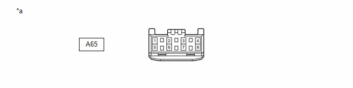
| *a | Front view of wire harness connector (to No. 2 Global CAN Junction Connector) | - | - |
(2) Check the connection diagram of the components which are connected to the No. 2 global CAN junction connector.
| Terminal No. (Symbol) | Wiring Color | Connected to |
|---|---|---|
| A65-1 (CANH) | LG | No. 11 global CAN junction connector (for Bus 1) |
| A65-5 (CANL) | W | |
| A65-2 (CANH) | L | Front side radar sensor (A)* (for Bus 1) |
| A65-6 (CANL) | W | |
| A65-3 (CANH) | R | Millimeter wave radar sensor assembly (for Bus 1) |
| A65-7 (CANL) | W |
- *: w/ Front Side Radar Sensor System
NO. 3 GLOBAL CAN JUNCTION CONNECTOR
(a) Check the No. 3 global CAN junction connector.
(1) Connection diagram
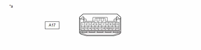
| *a | Front view of wire harness connector (to No. 3 Global CAN Junction Connector) | - | - |
(2) Check the connection diagram of the components which are connected to the No. 3 global CAN junction connector.
| Terminal No. (Symbol) | Wiring Color | Connected to |
|---|---|---|
| A17-1 (CANH) | G | No. 2 skid control ECU (brake actuator assembly) (for Bus 4) |
| A17-12 (CANL) | W | |
| A17-2 (CANH) | L | No. 1 skid control ECU (brake booster with master cylinder assembly) (for Bus 4) |
| A17-13 (CANL) | W | |
| A17-3 (CANH) | B | No. 4 global CAN junction connector (for Bus 4) |
| A17-14 (CANL) | W |
NO. 4 GLOBAL CAN JUNCTION CONNECTOR
(a) Check the No. 4 global CAN junction connector.
(1) Connection diagram
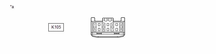
| *a | Front view of wire harness connector (to No. 4 Global CAN Junction Connector) | - | - |
(2) Check the connection diagram of the components which are connected to the No. 4 global CAN junction connector.
| Terminal No. (Symbol) | Wiring Color | Connected to |
|---|---|---|
| K105-1 (CANH) | R | Airbag ECU assembly (for Bus 4) |
| K105-5 (CANL) | W | |
| K105-2 (CANH) | B | No. 3 global CAN junction connector (for Bus 4) |
| K105-6 (CANL) | W | |
| K105-3 (CANH) | LG | Steering sensor (for Bus 4) |
| K105-7 (CANL) | W | |
| K105-4 (CANH) | G | Power steering ECU assembly (for Bus 4) |
| K105-8 (CANL) | W |
NO. 5 GLOBAL CAN JUNCTION CONNECTOR
(a) Check the No. 5 global CAN junction connector.
(1) Connection diagram

| *a | Front view of wire harness connector (to No. 5 Global CAN Junction Connector) | - | - |
(2) Check the connection diagram of the components which are connected to the No. 5 global CAN junction connector.
| Terminal No. (Symbol) | Wiring Color | Connected to |
|---|---|---|
| K106-1 (CANH) | R | Hybrid Toyota Prius vehicle control ECU (for Bus 2) |
| K106-5 (CANL) | W | |
| K106-2 (CANH) | L | Transmission floor shift assembly (for Bus 2) |
| K106-6 (CANL) | W | |
| K106-3 (CANH) | LG | Inverter with converter assembly (for Bus 2) |
| K106-7 (CANL) | W | |
| K106-4 (CANH) | BR | Battery ECU assembly (for Bus 2) |
| K106-8 (CANL) | W |
NO. 6 GLOBAL CAN JUNCTION CONNECTOR
(a) Check the No. 6 global CAN junction connector.
(1) Connection diagram
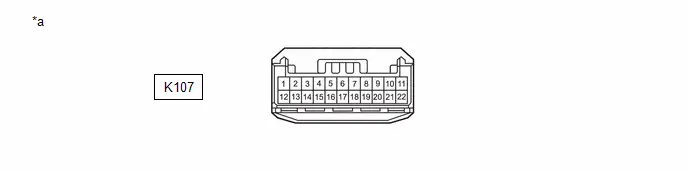
| *a | Front view of wire harness connector (to No. 6 Global CAN Junction Connector) | - | - |
(2) Check the connection diagram of the components which are connected to the No. 6 global CAN junction connector.
| Terminal No. (Symbol) | Wiring Color | Connected to |
|---|---|---|
| K107-1 (CANH) | LG | Transmission floor shift assembly (for Battery Local Bus) |
| K107-12 (CANL) | W | |
| K107-2 (CANH) | B | No. 2 junction connector (for Battery Local Bus) |
| K107-13 (CANL) | W | |
| K107-3 (CANH) | P | Battery ECU assembly (for Battery Local Bus) |
| K107-14 (CANL) | W | |
| K107-7 (CANH) | R | Certification ECU (smart key ECU assembly) (for Bus 5) |
| K107-18 (CANL) | W | |
| K107-8 (CANH) | L | Air conditioning amplifier assembly (for Bus 5) |
| K107-19 (CANL) | W | |
| K107-9 (CANH) | V | Central gateway ECU (network gateway ECU) (for Bus 5) |
| K107-20 (CANL) | W | |
| K107-10 (CANH) | G | No. 14 global CAN junction connector (for Bus 5) |
| K107-21 (CANL) | W |
NO. 7 GLOBAL CAN JUNCTION CONNECTOR
(a) Check the No. 7 global CAN junction connector.
(1) Connection diagram
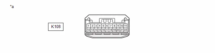
| *a | Front view of wire harness connector (to No. 7 Global CAN Junction Connector) | - | - |
(2) Check the connection diagram of the components which are connected to the No. 7 global CAN junction connector.
| Terminal No. (Symbol) | Wiring Color | Connected to |
|---|---|---|
| K108-1 (CANH) | L | Integration control supply (for Bus 6) |
| K108-12 (CANL) | W | |
| K108-2 (CANH) | G | Toyota Prius Vehicle approaching speaker controller (for Bus 6) |
| K108-13 (CANL) | W | |
| K108-3 (CANH) | LG | Central gateway ECU (network gateway ECU) (for Bus 6) |
| K108-14 (CANL) | W | |
| K108-4 (CANH) | P | No. 13 global CAN junction connector (for Bus 6) |
| K108-15 (CANL) | W | |
| K108-5 (CANH) | L | Tire pressure warning ECU and receiver (for Bus 6) |
| K108-16 (CANL) | W |
NO. 10 GLOBAL CAN JUNCTION CONNECTOR
(a) Check the No. 10 global CAN junction connector.
(1) Connection diagram
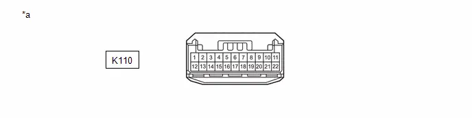
| *a | Front view of wire harness connector (to No. 10 Global CAN Junction Connector) | - | - |
(2) Check the connection diagram of the components which are connected to the No. 10 global CAN junction connector.
| Terminal No. (Symbol) | Wiring Color | Connected to |
|---|---|---|
| K110-1 (CANH) | L | Radio and display receiver assembly (for Bus 3) |
| K110-12 (CANL) | W | |
| K110-2 (CANH) | GR | DCM(telematics transceiver)*1 (for Bus 3) |
| K110-13 (CANL) | W | |
| K110-3 (CANH) | V | Combination meter assembly (for Bus 3) |
| K110-14 (CANL) | W | |
| K110-4 (CANH) | G | Central gateway ECU (network gateway ECU) (for Bus 3) |
| K110-15 (CANL) | W | |
| K110-6 (CANH) | R | Inner rear view mirror assembly*2 (for Bus 3) |
| K110-17 (CANL) | W |
- *1: w/ Telematics Transceiver
- *2: w/ Digital Inner Mirror System
NO. 11 GLOBAL CAN JUNCTION CONNECTOR
(a) Check the No. 11 global CAN junction connector.
(1) Connection diagram
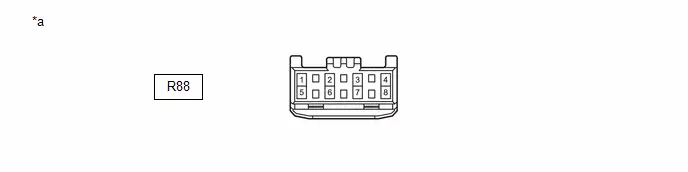
| *a | Front view of wire harness connector (to No. 11 Global CAN Junction Connector) | - | - |
(2) Check the connection diagram of the components which are connected to the No. 11 global CAN junction connector.
| Terminal No. (Symbol) | Wiring Color | Connected to |
|---|---|---|
| R88-1 (CANH) | LG | No. 2 global CAN junction connector (for Bus 1) |
| R88-5 (CANL) | W | |
| R88-2 (CANH) | R | Blind spot monitor sensor LH (B) (for Bus 1) |
| R88-6 (CANL) | W | |
| R88-3 (CANH) | GR | No. 16 global CAN junction connector*1 (for Bus 1) |
| R88-7 (CANL) | W | |
| R88-4 (CANH) | L | No. 2 CAN junction terminal*2 (for Bus 1) |
| R88-8 (CANL) | W |
- *1: w/ Parking Assist Monitor System
- *2: w/o Parking Assist Monitor System
NO. 12 GLOBAL CAN JUNCTION CONNECTOR (w/ Panoramic View Monitor System)
(a) Check the No. 12 global CAN junction connector.
(1) Connection diagram
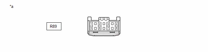
| *a | Front view of wire harness connector (to No. 12 Global CAN Junction Connector) | - | - |
(2) Check the connection diagram of the components which are connected to the No. 12 global CAN junction connector.
| Terminal No. (Symbol) | Wiring Color | Connected to |
|---|---|---|
| R89-1 (CANH) | G | Parking assist ECU (for Bus 1) |
| R89-5 (CANL) | W | |
| R89-2 (CANH) | R | Forward recognition camera (for Bus 1) |
| R89-6 (CANL) | W | |
| R89-3 (CANH) | B | No. 15 global CAN junction connector (for Bus 1) |
| R89-7 (CANL) | W |
NO. 13 GLOBAL CAN JUNCTION CONNECTOR
(a) Check the No. 13 global CAN junction connector.
(1) Connection diagram
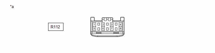
| *a | Front view of wire harness connector (to No. 13 Global CAN Junction Connector) | - | - |
(2) Check the connection diagram of the components which are connected to the No. 13 global CAN junction connector.
| Terminal No. (Symbol) | Wiring Color | Connected to |
|---|---|---|
| R112-1 (CANH) | G | No. 7 global CAN junction connector (for Bus 6) |
| R112-5 (CANL) | W | |
| R112-2 (CANH) | R | Central gateway ECU (network gateway ECU) (for Bus 6) |
| R112-6 (CANL) | W |
NO. 14 GLOBAL CAN JUNCTION CONNECTOR
(a) Check the No. 14 global CAN junction connector.
(1) Connection diagram

| *a | Front view of wire harness connector (to No. 14 Global CAN Junction Connector) | - | - |
(2) Check the connection diagram of the components which are connected to the No. 14 global CAN junction connector.
| Terminal No. (Symbol) | Wiring Color | Connected to |
|---|---|---|
| R91-1 (CANH) | L | Position control ECU assembly LH*1 (for Bus 5) |
| R91-5 (CANL) | W | |
| R91-2 (CANH) | V | Multiplex network door ECU*2 (for Bus 5) |
| R91-6 (CANL) | W | |
| R91-3 (CANH) | G | No. 6 global CAN junction connector (for Bus 5) |
| R91-7 (CANL) | W | |
| R91-4 (CANH) | R | Main body ECU (multiplex network body ECU) (for Bus 5) |
| R91-8 (CANL) | W |
- *1: w/ Seat Position Memory System
- *2: w/ Power Back Door System
NO. 15 GLOBAL CAN JUNCTION CONNECTOR
(a) Check the No. 15 global CAN junction connector.
(1) Connection diagram
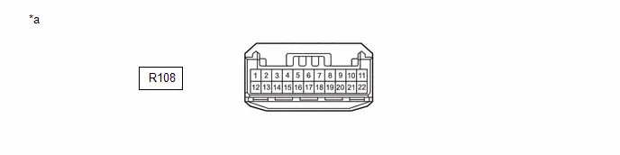
| *a | Front view of wire harness connector (to No. 15 Global CAN Junction Connector) | - | - |
(2) Check the connection diagram of the components which are connected to the No. 15 global CAN junction connector.
| Terminal No. (Symbol) | Wiring Color | Connected to |
|---|---|---|
| R108-1 (CANH) | B | Central gateway ECU (network gateway ECU) (for Bus 1) |
| R108-12 (CANL) | W | |
| R108-2 (CANH) | L | Clearance warning ECU assembly*1 (for Bus 1) |
| R108-13 (CANL) | W | |
| R108-3 (CANH) | SB | Forward recognition camera*2 (for Bus 1) |
| R108-14 (CANL) | W | |
| R108-4 (CANH) | B | No. 12 global CAN junction connector*3 (for Bus 1) |
| R108-15 (CANL) | W |
- *1: w/ Intuitive Parking Assist System
- *2: w/o Panoramic View Monitor System
- *3: w/ Panoramic View Monitor System
NO. 16 GLOBAL CAN JUNCTION CONNECTOR (w/ Parking Assist Monitor System)
(a) Check the No. 16 global CAN junction connector.
(1) Connection diagram
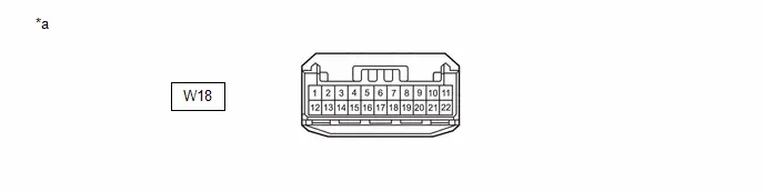
| *a | Front view of wire harness connector (to No. 16 Global CAN Junction Connector) | - | - |
(2) Check the connection diagram of the components which are connected to the No. 16 global CAN junction connector.
| Terminal No. (Symbol) | Wiring Color | Connected to |
|---|---|---|
| W18-5 (CANH) | LG | Rear television camera assembly (for Bus 1) |
| W18-16 (CANL) | W | |
| W18-6 (CANH) | L | No. 11 global CAN junction connector (for Bus 1) |
| W18-17 (CANL) | W | |
| W18-7 (CANH) | P | No. 2 CAN junction terminal (for Bus 1) |
| W18-18 (CANL) | W |
NO. 1 CAN JUNCTION CONNECTOR
(a) Check the No. 1 CAN junction connector.
(1) Connection diagram

| *a | Front view of wire harness connector (to No. 1 CAN Junction Connector) | - | - |
(2) Check the connection diagram of the components which are connected to the No. 1 CAN junction connector.
| Terminal No. (Symbol) | Wiring Color | Connected to |
|---|---|---|
| A63-1 (CANH) | BE | No. 1 skid control ECU (brake booster with master cylinder assembly) (for Powertrain Local Bus) |
| A63-5 (CANL) | W | |
| A63-2 (CANH) | P | Hybrid Toyota Prius vehicle control ECU (for Powertrain Local Bus) |
| A63-6 (CANL) | W | |
| A63-3 (CANH) | L | No. 2 CAN junction connector (for Powertrain Local Bus) |
| A63-7 (CANL) | W |
NO. 2 CAN JUNCTION CONNECTOR
(a) Check the No. 2 CAN junction connector.
(1) Connection diagram
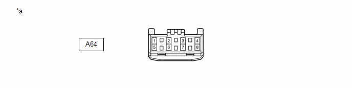
| *a | Front view of wire harness connector (to No. 2 CAN Junction Connector) | - | - |
(2) Check the connection diagram of the components which are connected to the No. 2 CAN junction connector.
| Terminal No. (Symbol) | Wiring Color | Connected to |
|---|---|---|
| A64-1 (CANH) | G | Inverter with converter assembly (for Powertrain Local Bus) |
| A64-5 (CANL) | W | |
| A64-2 (CANH) | V | No. 2 skid control ECU (brake actuator assembly) (for Powertrain Local Bus) |
| A64-6 (CANL) | W | |
| A64-3 (CANH) | B | ECM (for Powertrain Local Bus) |
| A64-7 (CANL) | W | |
| A64-4 (CANH) | L | No. 1 CAN junction connector (for Powertrain Local Bus) |
| A64-8 (CANL) | W |
NO. 2 JUNCTION CONNECTOR
(a) Check the No. 2 junction connector.
(1) Connection diagram
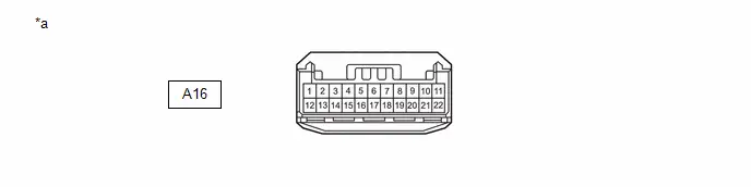
| *a | Front view of wire harness connector (to No. 2 Junction Connector) | - | - |
(2) Check the connection diagram of the components which are connected to the No. 2 junction connector.
| Terminal No. (Symbol) | Wiring Color | Connected to |
|---|---|---|
| A16-1 (CANH) | G | Shift control actuator assembly (for Battery Local Bus) |
| A16-12 (CANL) | W | |
| A16-2 (CANH) | SB | Hybrid Toyota Prius vehicle control ECU (for Battery Local Bus) |
| A16-13 (CANL) | W | |
| A16-3 (CANH) | R | Inverter with converter assembly (for Battery Local Bus) |
| A16-14 (CANL) | W | |
| A16-4 (CANH) | B | No. 6 global CAN junction connector (for Battery Local Bus) |
| A16-15 (CANL) | W |
NO. 2 CAN JUNCTION TERMINAL
(a) Check the No. 2 CAN junction terminal.
(1) Connection diagram
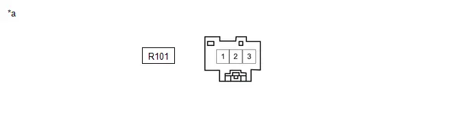
| *a | Front view of wire harness connector (to No. 2 CAN Junction Terminal) | - | - |
(2) Check the connection diagram of the components which are connected to the No. 2 CAN junction terminal.
| Terminal No. (Symbol) | Wiring Color | Connected to |
|---|---|---|
| R101-3 (CANH) | L | No. 11 global CAN junction connector*1 (for Bus 1) |
| R101-2 (CANL) | W | |
| R101-3 (CANH) | L | No. 16 global CAN junction connector*2 (for Bus 1) |
| R101-2 (CANL) | W |
- *1: w/o Parking Assist Monitor System
- *2: w/ Parking Assist Monitor System
DLC3
(a) Disconnect the cable from the negative (-) auxiliary battery terminal.
(b) Measure the resistance according to the value(s) in the table below.
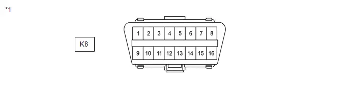
| *1 | DLC3 | - | - |
Standard Resistance:
| Terminal No. (Symbol) | Terminal Description | Condition | Specified Condition |
|---|---|---|---|
| K8-6 (CANH) - K8-14 (CANL) | HIGH-level CAN bus line - LOW-level CAN bus line | Cable disconnected from negative (-) auxiliary battery terminal | 54 to 69 Ω |
| K8-6 (CANH) - K8-4 (CG) | HIGH-level CAN bus line - Ground | Cable disconnected from negative (-) auxiliary battery terminal | 200 Ω or higher |
| K8-14 (CANL) - K8-4 (CG) | LOW-level CAN bus line - Ground | Cable disconnected from negative (-) auxiliary battery terminal | 200 Ω or higher |
| K8-6 (CANH) - K8-16 (BAT) | HIGH-level CAN bus line - Auxiliary battery positive ( ) | Cable disconnected from negative (-) auxiliary battery terminal | 6 kΩ or higher |
| K8-14 (CANL) - K8-16 (BAT) | LOW-level CAN bus line - Auxiliary battery positive ( ) | Cable disconnected from negative (-) auxiliary battery terminal | 6 kΩ or higher |
CENTRAL GATEWAY ECU (NETWORK GATEWAY ECU)
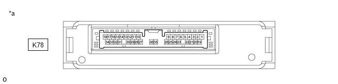
| *a | Component without harness connected (Central Gateway ECU (Network Gateway ECU)) | - | - |
(a) Disconnect the cable from the negative (-) auxiliary battery terminal.
(b) Disconnect the K78 central gateway ECU (network gateway ECU) connector.
(c) Measure the resistance according to the value(s) in the table below.
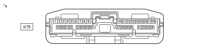
| *a | Front view of wire harness connector (to Central Gateway ECU (Network Gateway ECU)) | - | - |
Standard Resistance:
Diagnosis Bus Branch Lines (DLC3 - Central gateway ECU (network gateway ECU))| Terminal No. (Symbol) | Terminal Description | Condition | Specified Condition |
|---|---|---|---|
| K78-16 (CA6H) - K78-17 (CA6L) | HIGH-level CAN bus line - LOW-level CAN bus line | Cable disconnected from negative (-) auxiliary battery terminal | 1 MΩ or higher |
| K78-16 (CA6H) - K78-22 (GND) | HIGH-level CAN bus line - Ground | Cable disconnected from negative (-) auxiliary battery terminal | 200 Ω or higher |
| K78-17 (CA6L) - K78-22 (GND) | LOW-level CAN bus line - Ground | Cable disconnected from negative (-) auxiliary battery terminal | 200 Ω or higher |
| K78-16 (CA6H) - K78-1 (BATT) | HIGH-level CAN bus line - Auxiliary battery positive ( ) | Cable disconnected from negative (-) auxiliary battery terminal | 6 kΩ or higher |
| K78-17 (CA6L) - K78-1 (BATT) | LOW-level CAN bus line - Auxiliary battery positive ( ) | Cable disconnected from negative (-) auxiliary battery terminal | 6 kΩ or higher |
| Terminal No. (Symbol) | Terminal Description | Condition | Specified Condition |
|---|---|---|---|
| K78-28 (CA1H) - K78-27 (CA1L) | HIGH-level CAN bus line - LOW-level CAN bus line | Cable disconnected from negative (-) auxiliary battery terminal | 108 to 132 Ω |
| K78-28 (CA1H) - K78-22 (GND) | HIGH-level CAN bus line - Ground | Cable disconnected from negative (-) auxiliary battery terminal | 200 Ω or higher |
| K78-27 (CA1L) - K78-22 (GND) | LOW-level CAN bus line - Ground | Cable disconnected from negative (-) auxiliary battery terminal | 200 Ω or higher |
| K78-28 (CA1H) - K78-1 (BATT) | HIGH-level CAN bus line - Auxiliary battery positive ( ) | Cable disconnected from negative (-) auxiliary battery terminal | 6 kΩ or higher |
| K78-27 (CA1L) - K78-1 (BATT) | LOW-level CAN bus line - Auxiliary battery positive ( ) | Cable disconnected from negative (-) auxiliary battery terminal | 6 kΩ or higher |
| Terminal No. (Symbol) | Terminal Description | Condition | Specified Condition |
|---|---|---|---|
| K78-26 (CA4H) - K78-25 (CA4L) | HIGH-level CAN bus line - LOW-level CAN bus line | Cable disconnected from negative (-) auxiliary battery terminal | 108 to 132 Ω |
| K78-26 (CA4H) - K78-22 (GND) | HIGH-level CAN bus line - Ground | Cable disconnected from negative (-) auxiliary battery terminal | 200 Ω or higher |
| K78-25 (CA4L) - K78-22 (GND) | LOW-level CAN bus line - Ground | Cable disconnected from negative (-) auxiliary battery terminal | 200 Ω or higher |
| K78-26 (CA4H) - K78-1 (BATT) | HIGH-level CAN bus line - Auxiliary battery positive ( ) | Cable disconnected from negative (-) auxiliary battery terminal | 6 kΩ or higher |
| K78-25 (CA4L) - K78-1 (BATT) | LOW-level CAN bus line - Auxiliary battery positive ( ) | Cable disconnected from negative (-) auxiliary battery terminal | 6 kΩ or higher |
| Terminal No. (Symbol) | Terminal Description | Condition | Specified Condition |
|---|---|---|---|
| K78-30 (CA3H) - K78-29 (CA3L) | HIGH-level CAN bus line - LOW-level CAN bus line | Cable disconnected from negative (-) auxiliary battery terminal | 108 to 132 Ω |
| K78-30 (CA3H) - K78-22 (GND) | HIGH-level CAN bus line - Ground | Cable disconnected from negative (-) auxiliary battery terminal | 200 Ω or higher |
| K78-29 (CA3L) - K78-22 (GND) | LOW-level CAN bus line - Ground | Cable disconnected from negative (-) auxiliary battery terminal | 200 Ω or higher |
| K78-30 (CA3H) - K78-1 (BATT) | HIGH-level CAN bus line - Auxiliary battery positive ( ) | Cable disconnected from negative (-) auxiliary battery terminal | 6 kΩ or higher |
| K78-29 (CA3L) - K78-1 (BATT) | LOW-level CAN bus line - Auxiliary battery positive ( ) | Cable disconnected from negative (-) auxiliary battery terminal | 6 kΩ or higher |
| Terminal No. (Symbol) | Terminal Description | Condition | Specified Condition |
|---|---|---|---|
| K78-24 (CA2H) - K78-23 (CA2L) | HIGH-level CAN bus line - LOW-level CAN bus line | Cable disconnected from negative (-) auxiliary battery terminal | 108 to 132 Ω |
| K78-24 (CA2H) - K78-22 (GND) | HIGH-level CAN bus line - Ground | Cable disconnected from negative (-) auxiliary battery terminal | 200 Ω or higher |
| K78-23 (CA2L) - K78-22 (GND) | LOW-level CAN bus line - Ground | Cable disconnected from negative (-) auxiliary battery terminal | 200 Ω or higher |
| K78-24 (CA2H) - K78-1 (BATT) | HIGH-level CAN bus line - Auxiliary battery positive ( ) | Cable disconnected from negative (-) auxiliary battery terminal | 6 kΩ or higher |
| K78-23 (CA2L) - K78-1 (BATT) | LOW-level CAN bus line - Auxiliary battery positive ( ) | Cable disconnected from negative (-) auxiliary battery terminal | 6 kΩ or higher |
| Terminal No. (Symbol) | Terminal Description | Condition | Specified Condition |
|---|---|---|---|
| K78-7 (CA5H) - K78-8 (CA5L) | HIGH-level CAN bus line - LOW-level CAN bus line | Cable disconnected from negative (-) auxiliary battery terminal | 108 to 132 Ω |
| K78-7 (CA5H) - K78-22 (GND) | HIGH-level CAN bus line - Ground | Cable disconnected from negative (-) auxiliary battery terminal | 200 Ω or higher |
| K78-8 (CA5L) - K78-22 (GND) | LOW-level CAN bus line - Ground | Cable disconnected from negative (-) auxiliary battery terminal | 200 Ω or higher |
| K78-7 (CA5H) - K78-1 (BATT) | HIGH-level CAN bus line - Auxiliary battery positive ( ) | Cable disconnected from negative (-) auxiliary battery terminal | 6 kΩ or higher |
| K78-8 (CA5L) - K78-1 (BATT) | LOW-level CAN bus line - Auxiliary battery positive ( ) | Cable disconnected from negative (-) auxiliary battery terminal | 6 kΩ or higher |
| Terminal No. (Symbol) | Terminal Description | Condition | Specified Condition |
|---|---|---|---|
| K78-31 (CA7H) - K78-10 (CAVH) | HIGH-level CAN bus line - HIGH-level CAN bus line | Cable disconnected from negative (-) auxiliary battery terminal | Below 1 Ω |
| K78-32 (CA7L) - K78-11 (CAVL) | LOW-level CAN bus line - LOW-level CAN bus line | Cable disconnected from negative (-) auxiliary battery terminal | Below 1 Ω |
| K78-31 (CA7H) - K78-22 (GND) | HIGH-level CAN bus line - Ground | Cable disconnected from negative (-) auxiliary battery terminal | 200 Ω or higher |
| K78-32 (CA7L) - K78-22 (GND) | LOW-level CAN bus line - Ground | Cable disconnected from negative (-) auxiliary battery terminal | 200 Ω or higher |
| K78-31 (CA7H) - K78-1 (BATT) | HIGH-level CAN bus line - Auxiliary battery positive ( ) | Cable disconnected from negative (-) auxiliary battery terminal | 6 kΩ or higher |
| K78-32 (CA7L) - K78-1 (BATT) | LOW-level CAN bus line - Auxiliary battery positive ( ) | Cable disconnected from negative (-) auxiliary battery terminal | 6 kΩ or higher |
| Terminal No. (Symbol) | Terminal Description | Condition | Specified Condition |
|---|---|---|---|
| K78-5 (CA8H) - K78-6 (CA8L) | HIGH-level CAN bus line - LOW-level CAN bus line | Cable disconnected from negative (-) auxiliary battery terminal | 108 to 132 Ω |
| K78-5 (CA8H) - K78-22 (GND) | HIGH-level CAN bus line - Ground | Cable disconnected from negative (-) auxiliary battery terminal | 200 Ω or higher |
| K78-6 (CA8L) - K78-22 (GND) | LOW-level CAN bus line - Ground | Cable disconnected from negative (-) auxiliary battery terminal | 200 Ω or higher |
| K78-5 (CA8H) - K78-1 (BATT) | HIGH-level CAN bus line - Auxiliary battery positive ( ) | Cable disconnected from negative (-) auxiliary battery terminal | 6 kΩ or higher |
| K78-6 (CA8L) - K78-1 (BATT) | LOW-level CAN bus line - Auxiliary battery positive ( ) | Cable disconnected from negative (-) auxiliary battery terminal | 6 kΩ or higher |
STEERING SENSOR
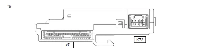
| *a | Component without harness connected (Steering Sensor) | - | - |
(a) Disconnect the cable from the negative (-) auxiliary battery terminal.
(b) Disconnect the K72 steering sensor connector.
(c) Measure the resistance according to the value(s) in the table below.
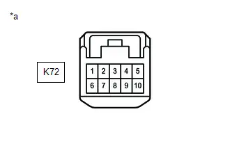
| *a | Front view of wire harness connector (to Steering Sensor) |
Standard Resistance:
| Terminal No. (Symbol) | Terminal Description | Condition | Specified Condition |
|---|---|---|---|
| K72-3 (CANH) - K72-8 (CANL) | HIGH-level CAN bus line - LOW-level CAN bus line | Cable disconnected from negative (-) auxiliary battery terminal | 54 to 69 Ω |
| K72-3 (CANH) - K72-6 (ESS) | HIGH-level CAN bus line - Ground | Cable disconnected from negative (-) auxiliary battery terminal | 200 Ω or higher |
| K72-8 (CANL) - K72-6 (ESS) | LOW-level CAN bus line - Ground | Cable disconnected from negative (-) auxiliary battery terminal | 200 Ω or higher |
| K72-3 (CANH) - K72-4 (BAT) | HIGH-level CAN bus line - Auxiliary battery positive ( ) | Cable disconnected from negative (-) auxiliary battery terminal | 6 kΩ or higher |
| K72-8 (CANL) - K72-4 (BAT) | LOW-level CAN bus line - Auxiliary battery positive ( ) | Cable disconnected from negative (-) auxiliary battery terminal | 6 kΩ or higher |
HYBRID Toyota Prius Vehicle CONTROL ECU
Refer to Terminals of ECU.
-
for M20A-FXS
Click here

-
for 2ZR-FXE:
Click here

(a) Disconnect the cable from the negative (-) auxiliary battery terminal.
(b) Disconnect the K11 hybrid Toyota Prius vehicle control ECU connector.
(c) Measure the resistance according to the value(s) in the table below.
Standard Resistance:
Bus 2 Branch Lines| Terminal No. (Symbol) | Terminal Description | Condition | Specified Condition |
|---|---|---|---|
| K11-51 (CA1H) - K11-52 (CA1L) | HIGH-level CAN bus line - LOW-level CAN bus line | Cable disconnected from negative (-) auxiliary battery terminal | 54 to 69 Ω |
| K11-51 (CA1H) - K11-1 (E1) | HIGH-level CAN bus line - Ground | Cable disconnected from negative (-) auxiliary battery terminal | 200 Ω or higher |
| K11-52 (CA1L) - K11-1 (E1) | LOW-level CAN bus line - Ground | Cable disconnected from negative (-) auxiliary battery terminal | 200 Ω or higher |
| K11-51 (CA1H) - K11-13 (BATT) | HIGH-level CAN bus line - Auxiliary battery positive ( ) | Cable disconnected from negative (-) auxiliary battery terminal | 6 kΩ or higher |
| K11-52 (CA1L) - K11-13 (BATT) | LOW-level CAN bus line - Auxiliary battery positive ( ) | Cable disconnected from negative (-) auxiliary battery terminal | 6 kΩ or higher |
| Terminal No. (Symbol) | Terminal Description | Condition | Specified Condition |
|---|---|---|---|
| K11-9 (CA4H) - K11-22 (CA4L) | HIGH-level CAN bus line - LOW-level CAN bus line | Cable disconnected from negative (-) auxiliary battery terminal | 108 to 132 Ω |
| K11-9 (CA4H) - K11-1 (E1) | HIGH-level CAN bus line - Ground | Cable disconnected from negative (-) auxiliary battery terminal | 200 Ω or higher |
| K11-22 (CA4L) - K11-1 (E1) | LOW-level CAN bus line - Ground | Cable disconnected from negative (-) auxiliary battery terminal | 200 Ω or higher |
| K11-9 (CA4H) - K11-13 (BATT) | HIGH-level CAN bus line - Auxiliary battery positive ( ) | Cable disconnected from negative (-) auxiliary battery terminal | 6 kΩ or higher |
| K11-22 (CA4L) - K11-13 (BATT) | LOW-level CAN bus line - Auxiliary battery positive ( ) | Cable disconnected from negative (-) auxiliary battery terminal | 6 kΩ or higher |
| Terminal No. (Symbol) | Terminal Description | Condition | Specified Condition |
|---|---|---|---|
| K11-50 (CA3P) - K11-49 (CA3N) | HIGH-level CAN bus line - LOW-level CAN bus line | Cable disconnected from negative (-) auxiliary battery terminal | 108 to 132 Ω |
| K11-50 (CA3P) - K11-1 (E1) | HIGH-level CAN bus line - Ground | Cable disconnected from negative (-) auxiliary battery terminal | 200 Ω or higher |
| K11-49 (CA3N) - K11-1 (E1) | LOW-level CAN bus line - Ground | Cable disconnected from negative (-) auxiliary battery terminal | 200 Ω or higher |
| K11-50 (CA3P) - K11-13 (BATT) | HIGH-level CAN bus line - Auxiliary battery positive ( ) | Cable disconnected from negative (-) auxiliary battery terminal | 6 kΩ or higher |
| K11-49 (CA3N) - K11-13 (BATT) | LOW-level CAN bus line - Auxiliary battery positive ( ) | Cable disconnected from negative (-) auxiliary battery terminal | 6 kΩ or higher |
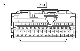
| *a | Front view of wire harness connector (to Hybrid Toyota Prius Vehicle Control ECU) |
INVERTER WITH CONVERTER ASSEMBLY
Refer to Terminals of ECU.
-
for M20A-FXS:
Click here

-
for 2ZR-FXE:
Click here

(a) Disconnect the cable from the negative (-) auxiliary battery terminal.
(b) Disconnect the A88 inverter with converter assembly connector.
(c) Measure the resistance according to the value(s) in the table below.
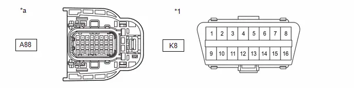
| *1 | DLC3 | - | - |
| *a | Front view of wire harness connector (to Inverter with Converter Assembly) | - | - |
Standard Resistance:
Bus 2 Main Lines| Terminal No. (Symbol) | Terminal Description | Condition | Specified Condition |
|---|---|---|---|
| A88-5 (CANH) - A88-6 (CANL) | HIGH-level CAN bus line - LOW-level CAN bus line | Cable disconnected from negative (-) auxiliary battery terminal | 108 to 132 Ω |
| A88-5 (CANH) - K8-4 (CG) | HIGH-level CAN bus line - Ground | Cable disconnected from negative (-) auxiliary battery terminal | 200 Ω or higher |
| A88-6 (CANL) - K8-4 (CG) | LOW-level CAN bus line - Ground | Cable disconnected from negative (-) auxiliary battery terminal | 200 Ω or higher |
| A88-5 (CANH) - K8-16 (BAT) | HIGH-level CAN bus line - Auxiliary battery positive ( ) | Cable disconnected from negative (-) auxiliary battery terminal | 6 kΩ or higher |
| A88-6 (CANL) - K8-16 (BAT) | LOW-level CAN bus line - Auxiliary battery positive ( ) | Cable disconnected from negative (-) auxiliary battery terminal | 6 kΩ or higher |
| A88-13 (CADH) - A88-14 (CADL) | HIGH-level CAN bus line - LOW-level CAN bus line | Cable disconnected from negative (-) auxiliary battery terminal | 108 to 132 Ω |
| A88-13 (CADH) - K8-4 (CG) | HIGH-level CAN bus line - Ground | Cable disconnected from negative (-) auxiliary battery terminal | 200 Ω or higher |
| A88-14 (CADL) - K8-4 (CG) | LOW-level CAN bus line - Ground | Cable disconnected from negative (-) auxiliary battery terminal | 200 Ω or higher |
| A88-13 (CADH) - K8-16 (BAT) | HIGH-level CAN bus line - Auxiliary battery positive ( ) | Cable disconnected from negative (-) auxiliary battery terminal | 6 kΩ or higher |
| A88-14 (CADL) - K8-16 (BAT) | LOW-level CAN bus line - Auxiliary battery positive ( ) | Cable disconnected from negative (-) auxiliary battery terminal | 6 kΩ or higher |
| Terminal No. (Symbol) | Terminal Description | Condition | Specified Condition |
|---|---|---|---|
| A88-3 (CALH) - A88-11 (CALL) | HIGH-level CAN bus line - LOW-level CAN bus line | Cable disconnected from negative (-) auxiliary battery terminal | 54 to 69 Ω |
| A88-3 (CALH) - K8-4 (CG) | HIGH-level CAN bus line - Ground | Cable disconnected from negative (-) auxiliary battery terminal | 200 Ω or higher |
| A88-11 (CALL) - K8-4 (CG) | LOW-level CAN bus line - Ground | Cable disconnected from negative (-) auxiliary battery terminal | 200 Ω or higher |
| A88-3 (CALH) - K8-16 (BAT) | HIGH-level CAN bus line - Auxiliary battery positive ( ) | Cable disconnected from negative (-) auxiliary battery terminal | 6 kΩ or higher |
| A88-11 (CALL) - K8-16 (BAT) | LOW-level CAN bus line - Auxiliary battery positive ( ) | Cable disconnected from negative (-) auxiliary battery terminal | 6 kΩ or higher |
(d) Disconnect the A89 inverter with converter assembly connector.
(e) Measure the resistance according to the value(s) in the table below.
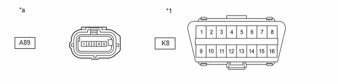
| *1 | DLC3 | - | - |
| *a | Front view of wire harness connector (to Inverter with Converter Assembly) | - | - |
Standard Resistance:
Battery Local Bus Branch Lines| Terminal No. (Symbol) | Terminal Description | Condition | Specified Condition |
|---|---|---|---|
| A89-5 (CNH) - A89-4 (CNL) | HIGH-level CAN bus line - LOW-level CAN bus line | Cable disconnected from negative (-) auxiliary battery terminal | 54 to 69 Ω |
| A89-5 (CNH) - K8-4 (CG) | HIGH-level CAN bus line - Ground | Cable disconnected from negative (-) auxiliary battery terminal | 200 Ω or higher |
| A89-4 (CNL) - K8-4 (CG) | LOW-level CAN bus line - Ground | Cable disconnected from negative (-) auxiliary battery terminal | 200 Ω or higher |
| A89-5 (CNH) - K8-16 (BAT) | HIGH-level CAN bus line - Auxiliary battery positive ( ) | Cable disconnected from negative (-) auxiliary battery terminal | 6 kΩ or higher |
| A89-4 (CNL) - K8-16 (BAT) | LOW-level CAN bus line - Auxiliary battery positive ( ) | Cable disconnected from negative (-) auxiliary battery terminal | 6 kΩ or higher |
ECM (for 2ZR-FXE)
Refer to Terminals of ECU.
Click here

(a) Disconnect the cable from the negative (-) auxiliary battery terminal.
(b) Disconnect the A91 ECM connector.
(c) Measure the resistance according to the value(s) in the table below.
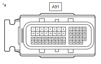
| *a | Front view of wire harness connector (to ECM) |
Standard Resistance:
Bus 2 Main Lines| Terminal No. (Symbol) | Terminal Description | Condition | Specified Condition |
|---|---|---|---|
| A91-9 (CFDH) - A91-10 (CFDL) | HIGH-level CAN bus line - LOW-level CAN bus line | Cable disconnected from negative (-) auxiliary battery terminal | 108 to 132 Ω |
| A91-9 (CFDH) - A91-17 (E1) | HIGH-level CAN bus line - Ground | Cable disconnected from negative (-) auxiliary battery terminal | 200 Ω or higher |
| A91-10 (CFDL) - A91-17 (E1) | LOW-level CAN bus line - Ground | Cable disconnected from negative (-) auxiliary battery terminal | 200 Ω or higher |
| A91-9 (CFDH) - A91-1 (BATT) | HIGH-level CAN bus line - Auxiliary battery positive ( ) | Cable disconnected from negative (-) auxiliary battery terminal | 6 kΩ or higher |
| A91-10 (CFDL) - A91-1 (BATT) | LOW-level CAN bus line - Auxiliary battery positive ( ) | Cable disconnected from negative (-) auxiliary battery terminal | 6 kΩ or higher |
| Terminal No. (Symbol) | Terminal Description | Condition | Specified Condition |
|---|---|---|---|
| A91-11 (CFDT) - A91-12 (CFDB) | HIGH-level CAN bus line - LOW-level CAN bus line | Cable disconnected from negative (-) auxiliary battery terminal | 54 to 69 Ω |
| A91-11 (CFDT) - A91-17 (E1) | HIGH-level CAN bus line - Ground | Cable disconnected from negative (-) auxiliary battery terminal | 200 Ω or higher |
| A91-12 (CFDB) - A91-17 (E1) | LOW-level CAN bus line - Ground | Cable disconnected from negative (-) auxiliary battery terminal | 200 Ω or higher |
| A91-11 (CFDT) - A91-1 (BATT) | HIGH-level CAN bus line - Auxiliary battery positive ( ) | Cable disconnected from negative (-) auxiliary battery terminal | 6 kΩ or higher |
| A91-12 (CFDB) - A91-1 (BATT) | LOW-level CAN bus line - Auxiliary battery positive ( ) | Cable disconnected from negative (-) auxiliary battery terminal | 6 kΩ or higher |
ECM (for M20A-FXS)
Refer to Terminals of ECU.
Click here


(a) Disconnect the cable from the negative (-) auxiliary battery terminal.
(b) Disconnect the A92 ECM connector.
(c) Measure the resistance according to the value(s) in the table below.
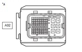
| *a | Front view of wire harness connector (to ECM) |
Standard Resistance:
Bus 2 Main Lines| Terminal No. (Symbol) | Terminal Description | Condition | Specified Condition |
|---|---|---|---|
| A92-7 (CFDH) - A92-8 (CFDL) | HIGH-level CAN bus line - LOW-level CAN bus line | Cable disconnected from negative (-) auxiliary battery terminal | 108 to 132 Ω |
| A92-7 (CFDH) - A92-10 (E1) | HIGH-level CAN bus line - Ground | Cable disconnected from negative (-) auxiliary battery terminal | 200 Ω or higher |
| A92-8 (CFDL) - A92-10 (E1) | LOW-level CAN bus line - Ground | Cable disconnected from negative (-) auxiliary battery terminal | 200 Ω or higher |
| A92-7 (CFDH) - A92-1 (BATT) | HIGH-level CAN bus line - Auxiliary battery positive ( ) | Cable disconnected from negative (-) auxiliary battery terminal | 6 kΩ or higher |
| A92-8 (CFDL) - A92-1 (BATT) | LOW-level CAN bus line - Auxiliary battery positive ( ) | Cable disconnected from negative (-) auxiliary battery terminal | 6 kΩ or higher |
| Terminal No. (Symbol) | Terminal Description | Condition | Specified Condition |
|---|---|---|---|
| A92-5 (CFDT) - A92-6 (CFDB) | HIGH-level CAN bus line - LOW-level CAN bus line | Cable disconnected from negative (-) auxiliary battery terminal | 54 to 69 Ω |
| A92-5 (CFDT) - A92-10 (E1) | HIGH-level CAN bus line - Ground | Cable disconnected from negative (-) auxiliary battery terminal | 200 Ω or higher |
| A92-6 (CFDB) - A92-10 (E1) | LOW-level CAN bus line - Ground | Cable disconnected from negative (-) auxiliary battery terminal | 200 Ω or higher |
| A92-5 (CFDT) - A92-1 (BATT) | HIGH-level CAN bus line - Auxiliary battery positive ( ) | Cable disconnected from negative (-) auxiliary battery terminal | 6 kΩ or higher |
| A92-6 (CFDB) - A92-1 (BATT) | LOW-level CAN bus line - Auxiliary battery positive ( ) | Cable disconnected from negative (-) auxiliary battery terminal | 6 kΩ or higher |
COMBINATION METER ASSEMBLY
Refer to Terminals of ECU.
Click here

(a) Disconnect the cable from the negative (-) auxiliary battery terminal.
(b) Disconnect the K18 and K19 combination meter assembly connectors.
(c) Measure the resistance according to the value(s) in the table below.
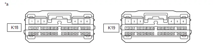
| *a | Front view of wire harness connector (to Combination Meter Assembly) | - | - |
Standard Resistance:
| Terminal No. (Symbol) | Terminal Description | Condition | Specified Condition |
|---|---|---|---|
| K19-31 (CANH) - K19-14 (CANL) | HIGH-level CAN bus line - LOW-level CAN bus line | Cable disconnected from negative (-) auxiliary battery terminal | 108 to 132 Ω |
| K19-31 (CANH) - K18-2 (ES) | HIGH-level CAN bus line - Ground | Cable disconnected from negative (-) auxiliary battery terminal | 200 Ω or higher |
| K19-14 (CANL) - K18-2 (ES) | LOW-level CAN bus line - Ground | Cable disconnected from negative (-) auxiliary battery terminal | 200 Ω or higher |
| K19-31 (CANH) - K19-2 (B) | HIGH-level CAN bus line - Auxiliary battery positive ( ) | Cable disconnected from negative (-) auxiliary battery terminal | 6 kΩ or higher |
| K19-14 (CANL) - K19-2 (B) | LOW-level CAN bus line - Auxiliary battery positive ( ) | Cable disconnected from negative (-) auxiliary battery terminal | 6 kΩ or higher |
NO. 1 SKID CONTROL ECU (BRAKE BOOSTER WITH MASTER CYLINDER ASSEMBLY)
Refer to Terminals of ECU.
Click here

(a) Disconnect the cable from the negative (-) auxiliary battery terminal.
(b) Disconnect the A3 No. 1 skid control ECU (brake booster with master cylinder assembly) connector.
(c) Measure the resistance according to the value(s) in the table below.
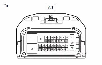
| *a | Front view of wire harness connector (to No. 1 Skid Control ECU (Brake Booster with Master Cylinder Assembly)) |
Standard Resistance:
Bus 4 Main Lines| Terminal No. (Symbol) | Terminal Description | Condition | Specified Condition |
|---|---|---|---|
| A3-36 (CA1H) - A3-37 (CA1L) | HIGH-level CAN bus line - LOW-level CAN bus line | Cable disconnected from negative (-) auxiliary battery terminal | 108 to 132 Ω |
| A3-36 (CA1H) - A3-21 (GND2) | HIGH-level CAN bus line - Ground | Cable disconnected from negative (-) auxiliary battery terminal | 200 Ω or higher |
| A3-37 (CA1L) - A3-21 (GND2) | LOW-level CAN bus line - Ground | Cable disconnected from negative (-) auxiliary battery terminal | 200 Ω or higher |
| A3-36 (CA1H) - A3-11 (BS) | HIGH-level CAN bus line - Auxiliary battery positive ( ) | Cable disconnected from negative (-) auxiliary battery terminal | 6 kΩ or higher |
| A3-37 (CA1L) - A3-11 (BS) | LOW-level CAN bus line - Auxiliary battery positive ( ) | Cable disconnected from negative (-) auxiliary battery terminal | 6 kΩ or higher |
| A3-34 (DC1H) - A3-35 (DC1L) | HIGH-level CAN bus line - LOW-level CAN bus line | Cable disconnected from negative (-) auxiliary battery terminal | 108 to 132 Ω |
| A3-34 (DC1H) - A3-21 (GND2) | HIGH-level CAN bus line - Ground | Cable disconnected from negative (-) auxiliary battery terminal | 200 Ω or higher |
| A3-35 (DC1L) - A3-21 (GND2) | LOW-level CAN bus line - Ground | Cable disconnected from negative (-) auxiliary battery terminal | 200 Ω or higher |
| A3-34 (DC1H) - A3-11 (BS) | HIGH-level CAN bus line - Auxiliary battery positive ( ) | Cable disconnected from negative (-) auxiliary battery terminal | 6 kΩ or higher |
| A3-35 (DC1L) - A3-11 (BS) | LOW-level CAN bus line - Auxiliary battery positive ( ) | Cable disconnected from negative (-) auxiliary battery terminal | 6 kΩ or higher |
| Terminal No. (Symbol) | Terminal Description | Condition | Specified Condition |
|---|---|---|---|
| A3-4 (CA2H) - A3-13 (CA2L) | HIGH-level CAN bus line - LOW-level CAN bus line | Cable disconnected from negative (-) auxiliary battery terminal | 54 to 69 Ω |
| A3-4 (CA2H) - A3-21 (GND2) | HIGH-level CAN bus line - Ground | Cable disconnected from negative (-) auxiliary battery terminal | 200 Ω or higher |
| A3-13 (CA2L) - A3-21 (GND2) | LOW-level CAN bus line - Ground | Cable disconnected from negative (-) auxiliary battery terminal | 200 Ω or higher |
| A3-4 (CA2H) - A3-11 (BS) | HIGH-level CAN bus line - Auxiliary battery positive ( ) | Cable disconnected from negative (-) auxiliary battery terminal | 6 kΩ or higher |
| A3-13 (CA2L) - A3-11 (BS) | LOW-level CAN bus line - Auxiliary battery positive ( ) | Cable disconnected from negative (-) auxiliary battery terminal | 6 kΩ or higher |
NO. 2 SKID CONTROL ECU (BRAKE ACTUATOR ASSEMBLY)
Refer to Terminals of ECU.
Click here

(a) Disconnect the cable from the negative (-) auxiliary battery terminal.
(b) Disconnect the A4 No. 2 skid control ECU (brake actuator assembly) connector.
(c) Measure the resistance according to the value(s) in the table below.
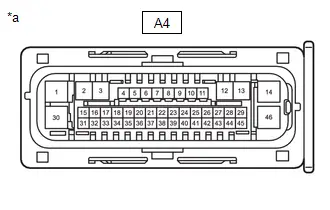
| *a | Front view of wire harness connector (to No. 2 Skid Control ECU (Brake Actuator Assembly)) |
Standard Resistance:
Bus 4 Branch Lines| Terminal No. (Symbol) | Terminal Description | Condition | Specified Condition |
|---|---|---|---|
| A4-27 (CANH) - A4-43 (CANL) | HIGH-level CAN bus line - LOW-level CAN bus line | Cable disconnected from negative (-) auxiliary battery terminal | 54 to 69 Ω |
| A4-27 (CANH) - A4-1 (GND1) | HIGH-level CAN bus line - Ground | Cable disconnected from negative (-) auxiliary battery terminal | 200 Ω or higher |
| A4-43 (CANL) - A4-1 (GND1) | LOW-level CAN bus line - Ground | Cable disconnected from negative (-) auxiliary battery terminal | 200 Ω or higher |
| A4-27 (CANH) - A4-14 ( BS) | HIGH-level CAN bus line - Auxiliary battery positive ( ) | Cable disconnected from negative (-) auxiliary battery terminal | 6 kΩ or higher |
| A4-43 (CANL) - A4-14 ( BS) | LOW-level CAN bus line - Auxiliary battery positive ( ) | Cable disconnected from negative (-) auxiliary battery terminal | 6 kΩ or higher |
| Terminal No. (Symbol) | Terminal Description | Condition | Specified Condition |
|---|---|---|---|
| A4-16 (CA2H) - A4-17 (CA2L) | HIGH-level CAN bus line - LOW-level CAN bus line | Cable disconnected from negative (-) auxiliary battery terminal | 108 to 132 Ω |
| A4-16 (CA2H) - A4-1 (GND1) | HIGH-level CAN bus line - Ground | Cable disconnected from negative (-) auxiliary battery terminal | 200 Ω or higher |
| A4-17 (CA2L) - A4-1 (GND1) | LOW-level CAN bus line - Ground | Cable disconnected from negative (-) auxiliary battery terminal | 200 Ω or higher |
| A4-16 (CA2H) - A4-14 ( BS) | HIGH-level CAN bus line - Auxiliary battery positive ( ) | Cable disconnected from negative (-) auxiliary battery terminal | 6 kΩ or higher |
| A4-17 (CA2L) - A4-14 ( BS) | LOW-level CAN bus line - Auxiliary battery positive ( ) | Cable disconnected from negative (-) auxiliary battery terminal | 6 kΩ or higher |
MAIN BODY ECU (MULTIPLEX NETWORK BODY ECU)
Refer to Terminals of ECU.
Click here


(a) Disconnect the cable from the negative (-) auxiliary battery terminal.
(b) Disconnect the K17 main body ECU (multiplex network body ECU) connector.
(c) Measure the resistance according to the value(s) in the table below.
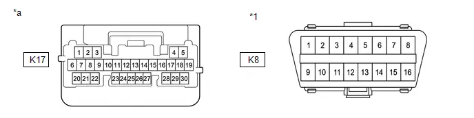
| *1 | DLC3 | - | - |
| *a | Front view of wire harness connector (to Main Body ECU (Multiplex Network Body ECU)) | - | - |
Standard Resistance:
| Terminal No. (Symbol) | Terminal Description | Condition | Specified Condition |
|---|---|---|---|
| K17-2 (CANH) - K17-1 (CANL) | HIGH-level CAN bus line - LOW-level CAN bus line | Cable disconnected from negative (-) auxiliary battery terminal | 108 to 132 Ω |
| K17-2 (CANH) - K8-4 (CG) | HIGH-level CAN bus line - Ground | Cable disconnected from negative (-) auxiliary battery terminal | 200 Ω or higher |
| K17-1 (CANL) - K8-4 (CG) | LOW-level CAN bus line - Ground | Cable disconnected from negative (-) auxiliary battery terminal | 200 Ω or higher |
| K17-2 (CANH) - K8-16 (BAT) | HIGH-level CAN bus line - Auxiliary battery positive ( ) | Cable disconnected from negative (-) auxiliary battery terminal | 6 kΩ or higher |
| K17-1 (CANL) - K8-16 (BAT) | LOW-level CAN bus line - Auxiliary battery positive ( ) | Cable disconnected from negative (-) auxiliary battery terminal | 6 kΩ or higher |
CERTIFICATION ECU (SMART KEY ECU ASSEMBLY)
Refer to Terminals of ECU.
Click here

(a) Disconnect the cable from the negative (-) auxiliary battery terminal.
(b) Disconnect the K13 certification ECU (smart key ECU assembly) connector.
(c) Measure the resistance according to the value(s) in the table below.
Standard Resistance:
| Terminal No. (Symbol) | Terminal Description | Condition | Specified Condition |
|---|---|---|---|
| K13-1 (CANH) - K13-2 (CANL) | HIGH-level CAN bus line - LOW-level CAN bus line | Cable disconnected from negative (-) auxiliary battery terminal | 54 to 69 Ω |
| K13-1 (CANH) - K13-29 (E) | HIGH-level CAN bus line - Ground | Cable disconnected from negative (-) auxiliary battery terminal | 200 Ω or higher |
| K13-2 (CANL) - K13-29 (E) | LOW-level CAN bus line - Ground | Cable disconnected from negative (-) auxiliary battery terminal | 200 Ω or higher |
| K13-1 (CANH) - K13-6 ( B) | HIGH-level CAN bus line - Auxiliary battery positive ( ) | Cable disconnected from negative (-) auxiliary battery terminal | 6 kΩ or higher |
| K13-2 (CANL) - K13-6 ( B) | LOW-level CAN bus line - Auxiliary battery positive ( ) | Cable disconnected from negative (-) auxiliary battery terminal | 6 kΩ or higher |
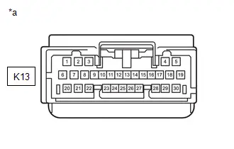
| *a | Front view of wire harness connector (to Certification ECU (Smart Key ECU Assembly)) |
POWER STEERING ECU ASSEMBLY
Refer to Terminals of ECU.
Click here

(a) Disconnect the cable from the negative (-) auxiliary battery terminal.
(b) Disconnect the K44 and K71 power steering ECU assembly connectors.
(c) Measure the resistance according to the value(s) in the table below.
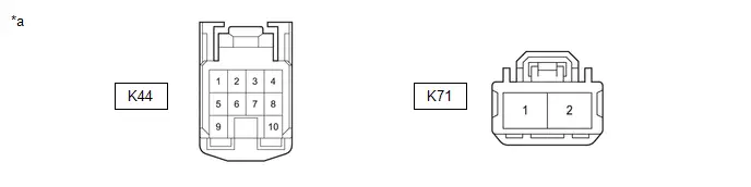
| *a | Front view of wire harness connector (to Power Steering ECU Assembly) | - | - |
Standard Resistance:
| Terminal No. (Symbol) | Terminal Description | Condition | Specified Condition |
|---|---|---|---|
| K44-7 (CANH) - K44-8 (CANL) | HIGH-level CAN bus line - LOW-level CAN bus line | Cable disconnected from negative (-) auxiliary battery terminal | 108 to 132 Ω |
| K44-7 (CANH) - K71-2 (PGND) | HIGH-level CAN bus line - Ground | Cable disconnected from negative (-) auxiliary battery terminal | 200 Ω or higher |
| K44-8 (CANL) - K71-2 (PGND) | LOW-level CAN bus line - Ground | Cable disconnected from negative (-) auxiliary battery terminal | 200 Ω or higher |
| K44-7 (CANH) - K71-1 (PIG) | HIGH-level CAN bus line - Auxiliary battery positive ( ) | Cable disconnected from negative (-) auxiliary battery terminal | 6 kΩ or higher |
| K44-8 (CANL) - K71-1 (PIG) | LOW-level CAN bus line - Auxiliary battery positive ( ) | Cable disconnected from negative (-) auxiliary battery terminal | 6 kΩ or higher |
AIRBAG ECU ASSEMBLY
Refer to Terminals of ECU.
Click here

(a) Disconnect the cable from the negative (-) auxiliary battery terminal.
(b) Disconnect the K1 airbag ECU assembly connector.
(c) Measure the resistance according to the value(s) in the table below.
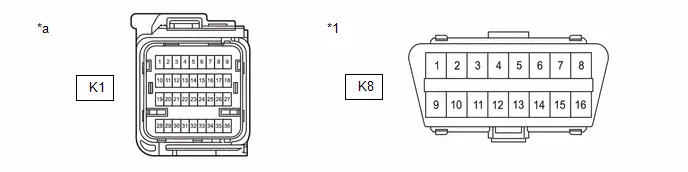
| *1 | DLC3 | - | - |
| *a | Front view of wire harness connector (to Airbag ECU Assembly) | - | - |
Standard Resistance:
| Terminal No. (Symbol) | Terminal Description | Condition | Specified Condition |
|---|---|---|---|
| K1-26 (CAFH) - K1-27 (CAFL) | HIGH-level CAN bus line - LOW-level CAN bus line | Cable disconnected from negative (-) auxiliary battery terminal | 54 to 69 Ω |
| K1-26 (CAFH) - K1-33 (E1) | HIGH-level CAN bus line - Ground | Cable disconnected from negative (-) auxiliary battery terminal | 200 Ω or higher |
| K1-27 (CAFL) - K1-33 (E1) | LOW-level CAN bus line - Ground | Cable disconnected from negative (-) auxiliary battery terminal | 200 Ω or higher |
| K1-26 (CAFH) - K8-16 (BAT) | HIGH-level CAN bus line - Auxiliary battery positive ( ) | Cable disconnected from negative (-) auxiliary battery terminal | 6 kΩ or higher |
| K1-27 (CAFL) - K8-16 (BAT) | LOW-level CAN bus line - Auxiliary battery positive ( ) | Cable disconnected from negative (-) auxiliary battery terminal | 6 kΩ or higher |
AIR CONDITIONING AMPLIFIER ASSEMBLY
Refer to Terminals of ECU.
Click here

(a) Disconnect the cable from the negative (-) auxiliary battery terminal.
(b) Disconnect the K74 air conditioning amplifier assembly connector.
(c) Measure the resistance according to the value(s) in the table below.
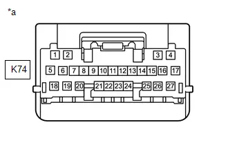
| *a | Front view of wire harness connector (to Air Conditioning Amplifier Assembly) |
Standard Resistance:
| Terminal No. (Symbol) | Terminal Description | Condition | Specified Condition |
|---|---|---|---|
| K74-2 (CANH) - K74-1 (CANL) | HIGH-level CAN bus line - LOW-level CAN bus line | Cable disconnected from negative (-) auxiliary battery terminal | 54 to 69 Ω |
| K74-2 (CANH) - K74-17 (GND) | HIGH-level CAN bus line - Ground | Cable disconnected from negative (-) auxiliary battery terminal | 200 Ω or higher |
| K74-1 (CANL) - K74-17 (GND) | LOW-level CAN bus line - Ground | Cable disconnected from negative (-) auxiliary battery terminal | 200 Ω or higher |
| K74-2 (CANH) - K74-5 (B) | HIGH-level CAN bus line - Auxiliary battery positive ( ) | Cable disconnected from negative (-) auxiliary battery terminal | 6 kΩ or higher |
| K74-1 (CANL) - K74-5 (B) | LOW-level CAN bus line - Auxiliary battery positive ( ) | Cable disconnected from negative (-) auxiliary battery terminal | 6 kΩ or higher |
BLIND SPOT MONITOR SENSOR LH (B)
Refer to Terminals of ECU.
Click here

(a) Disconnect the cable from the negative (-) auxiliary battery terminal.
(b) Disconnect the S6 blind spot monitor sensor LH (B) connector.
(c) Measure the resistance according to the value(s) in the table below.
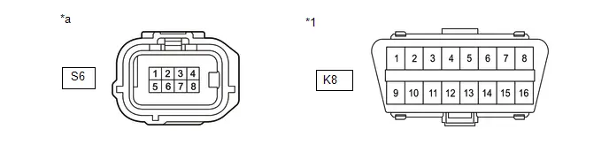
| *1 | DLC3 | - | - |
| *a | Front view of wire harness connector (to Blind Spot Monitor Sensor LH (B)) | - | - |
Standard Resistance:
| Terminal No. (Symbol) | Terminal Description | Condition | Specified Condition |
|---|---|---|---|
| S6-3 (CA1P) - S6-2 (CA1N) | HIGH-level CAN bus line - LOW-level CAN bus line | Cable disconnected from negative (-) auxiliary battery terminal | 54 to 69 Ω |
| S6-3 (CA1P) - S6-1 (BLGD) | HIGH-level CAN bus line - Ground | Cable disconnected from negative (-) auxiliary battery terminal | 200 Ω or higher |
| S6-2 (CA1N) - S6-1 (BLGD) | LOW-level CAN bus line - Ground | Cable disconnected from negative (-) auxiliary battery terminal | 200 Ω or higher |
| S6-3 (CA1P) - K8-16 (BAT) | HIGH-level CAN bus line - Auxiliary battery positive ( ) | Cable disconnected from negative (-) auxiliary battery terminal | 6 kΩ or higher |
| S6-2 (CA1N) - K8-16 (BAT) | LOW-level CAN bus line - Auxiliary battery positive ( ) | Cable disconnected from negative (-) auxiliary battery terminal | 6 kΩ or higher |
FORWARD RECOGNITION CAMERA
Refer to Terminals of ECU.
Click here

(a) Disconnect the cable from the negative (-) auxiliary battery terminal.
(b) Disconnect the U10 forward recognition camera connector.
(c) Measure the resistance according to the value(s) in the table below.
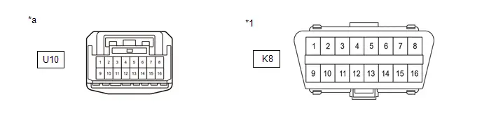
| *1 | DLC3 | - | - |
| *a | Front view of wire harness connector (to Forward Recognition Camera) | - | - |
Standard Resistance:
| Terminal No. (Symbol) | Terminal Description | Condition | Specified Condition |
|---|---|---|---|
| U10-2 (CA2P) - U10-1 (CA2L) | HIGH-level CAN bus line - LOW-level CAN bus line | Cable disconnected from negative (-) auxiliary battery terminal | 108 to 132 Ω |
| U10-2 (CA2P) - U10-13 (GND) | HIGH-level CAN bus line - Ground | Cable disconnected from negative (-) auxiliary battery terminal | 200 Ω or higher |
| U10-1 (CA2L) - U10-13 (GND) | LOW-level CAN bus line - Ground | Cable disconnected from negative (-) auxiliary battery terminal | 200 Ω or higher |
| U10-2 (CA2P) - K8-16 (BAT) | HIGH-level CAN bus line - Auxiliary battery positive ( ) | Cable disconnected from negative (-) auxiliary battery terminal | 6 kΩ or higher |
| U10-1 (CA2L) - K8-16 (BAT) | LOW-level CAN bus line - Auxiliary battery positive ( ) | Cable disconnected from negative (-) auxiliary battery terminal | 6 kΩ or higher |
| U10-10 (CA1P) - U10-9 (CA1N) | HIGH-level CAN bus line - LOW-level CAN bus line | Cable disconnected from negative (-) auxiliary battery terminal | 108 to 132 Ω |
| U10-10 (CA1P) - U10-13 (GND) | HIGH-level CAN bus line - Ground | Cable disconnected from negative (-) auxiliary battery terminal | 200 Ω or higher |
| U10-9 (CA1N) - U10-13 (GND) | LOW-level CAN bus line - Ground | Cable disconnected from negative (-) auxiliary battery terminal | 200 Ω or higher |
| U10-10 (CA1P) - K8-16 (BAT) | HIGH-level CAN bus line - Auxiliary battery positive ( ) | Cable disconnected from negative (-) auxiliary battery terminal | 6 kΩ or higher |
| U10-9 (CA1N) - K8-16 (BAT) | LOW-level CAN bus line - Auxiliary battery positive ( ) | Cable disconnected from negative (-) auxiliary battery terminal | 6 kΩ or higher |
MILLIMETER WAVE RADAR SENSOR ASSEMBLY
Refer to Terminals of ECU.
Click here

(a) Disconnect the cable from the negative (-) auxiliary battery terminal.
(b) Disconnect the A21 millimeter wave radar sensor assembly connector.
(c) Measure the resistance according to the value(s) in the table below.
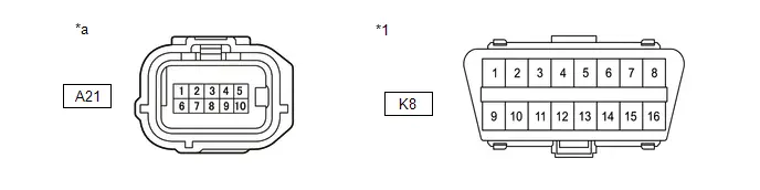
| *1 | DLC3 | - | - |
| *a | Front view of wire harness connector (to Millimeter Wave Radar Sensor Assembly) | - | - |
Standard Resistance:
| Terminal No. (Symbol) | Terminal Description | Condition | Specified Condition |
|---|---|---|---|
| A21-4 (CA2H) - A21-3 (CA2L) | HIGH-level CAN bus line - LOW-level CAN bus line | Cable disconnected from negative (-) auxiliary battery terminal | 108 to 132 Ω |
| A21-4 (CA2H) - A21-5 (SGND) | HIGH-level CAN bus line - Ground | Cable disconnected from negative (-) auxiliary battery terminal | 200 Ω or higher |
| A21-3 (CA2L) - A21-5 (SGND) | LOW-level CAN bus line - Ground | Cable disconnected from negative (-) auxiliary battery terminal | 200 Ω or higher |
| A21-4 (CA2H) - K8-16 (BAT) | HIGH-level CAN bus line - Auxiliary battery positive ( ) | Cable disconnected from negative (-) auxiliary battery terminal | 6 kΩ or higher |
| A21-3 (CA2L) - K8-16 (BAT) | LOW-level CAN bus line - Auxiliary battery positive ( ) | Cable disconnected from negative (-) auxiliary battery terminal | 6 kΩ or higher |
| A21-10 (CA3H) - A21-9 (CA3L) | HIGH-level CAN bus line - LOW-level CAN bus line | Cable disconnected from negative (-) auxiliary battery terminal | 108 to 132 Ω |
| A21-10 (CA3H) - A21-5 (SGND) | HIGH-level CAN bus line - Ground | Cable disconnected from negative (-) auxiliary battery terminal | 200 Ω or higher |
| A21-9 (CA3L) - A21-5 (SGND) | LOW-level CAN bus line - Ground | Cable disconnected from negative (-) auxiliary battery terminal | 200 Ω or higher |
| A21-10 (CA3H) - K8-16 (BAT) | HIGH-level CAN bus line - Auxiliary battery positive ( ) | Cable disconnected from negative (-) auxiliary battery terminal | 6 kΩ or higher |
| A21-9 (CA3L) - K8-16 (BAT) | LOW-level CAN bus line - Auxiliary battery positive ( ) | Cable disconnected from negative (-) auxiliary battery terminal | 6 kΩ or higher |
DCM(TELEMATICS TRANSCEIVER) (w/ Telematics Transceiver)
Refer to Terminals of ECU.
Click here

(a) Disconnect the cable from the negative (-) auxiliary battery terminal.
(b) Disconnect the K9 DCM(telematics transceiver) connector.
(c) Measure the resistance according to the value(s) in the table below.
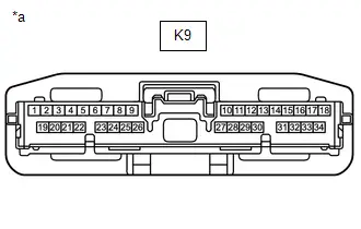
| *a | Front view of wire harness connector (to DCM(Telematics Transceiver)) |
Standard Resistance:
| Terminal No. (Symbol) | Terminal Description | Condition | Specified Condition |
|---|---|---|---|
| K9-25 (CANP) - K9-26 (CANN) | HIGH-level CAN bus line - LOW-level CAN bus line | Cable disconnected from negative (-) auxiliary battery terminal | 54 to 69 Ω |
| K9-25 (CANP) - K9-20 (E) | HIGH-level CAN bus line - Ground | Cable disconnected from negative (-) auxiliary battery terminal | 200 Ω or higher |
| K9-26 (CANN) - K9-20 (E) | LOW-level CAN bus line - Ground | Cable disconnected from negative (-) auxiliary battery terminal | 200 Ω or higher |
| K9-25 (CANP) - K9-1 ( B) | HIGH-level CAN bus line - Auxiliary battery positive ( ) | Cable disconnected from negative (-) auxiliary battery terminal | 6 kΩ or higher |
| K9-26 (CANN) - K9-1 ( B) | LOW-level CAN bus line - Auxiliary battery positive ( ) | Cable disconnected from negative (-) auxiliary battery terminal | 6 kΩ or higher |
Toyota Prius Vehicle APPROACHING SPEAKER CONTROLLER
Refer to Terminals of ECU.
Click here

(a) Disconnect the cable from the negative (-) auxiliary battery terminal.
(b) Disconnect the A59 vehicle approaching speaker controller connector.
(c) Measure the resistance according to the value(s) in the table below.
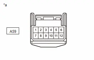
| *a | Front view of wire harness connector (to Toyota Prius Vehicle Approaching Speaker Controller) |
Standard Resistance:
| Terminal No. (Symbol) | Terminal Description | Condition | Specified Condition |
|---|---|---|---|
| A59-1 (CANH) - A59-2 (CANL) | HIGH-level CAN bus line - LOW-level CAN bus line | Cable disconnected from negative (-) auxiliary battery terminal | 54 to 69 Ω |
| A59-1 (CANH) - A59-12 (GND) | HIGH-level CAN bus line - Ground | Cable disconnected from negative (-) auxiliary battery terminal | 200 Ω or higher |
| A59-2 (CANL) - A59-12 (GND) | LOW-level CAN bus line - Ground | Cable disconnected from negative (-) auxiliary battery terminal | 200 Ω or higher |
| A59-1 (CANH) - A59-7 ( B) | HIGH-level CAN bus line - Auxiliary battery positive ( ) | Cable disconnected from negative (-) auxiliary battery terminal | 6 kΩ or higher |
| A59-2 (CANL) - A59-7 ( B) | LOW-level CAN bus line - Auxiliary battery positive ( ) | Cable disconnected from negative (-) auxiliary battery terminal | 6 kΩ or higher |
OPTION CONNECTOR (BUS BUFFER ECU)
(a) Disconnect the cable from the negative (-) auxiliary battery terminal.
(b) Disconnect the K79 option connector (bus buffer ECU) connector.
HINT:
Disconnect any CAN compatible optional devices from the option connector.
(c) Measure the resistance according to the value(s) in the table below.
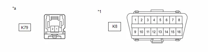
| *1 | DLC3 | - | - |
| *a | Front view of wire harness connector (to Option Connector (Bus Buffer ECU)) | - | - |
Standard Resistance:
| Terminal No. (Symbol) | Terminal Description | Condition | Specified Condition |
|---|---|---|---|
| K79-2 (CAN ) - K79-1 (CAN-) | HIGH-level CAN bus line - LOW-level CAN bus line | Cable disconnected from negative (-) auxiliary battery terminal | 108 to 132 Ω |
| K79-2 (CAN ) - K8-4 (CG) | HIGH-level CAN bus line - Ground | Cable disconnected from negative (-) auxiliary battery terminal | 200 Ω or higher |
| K79-1 (CAN-) - K8-4 (CG) | LOW-level CAN bus line - Ground | Cable disconnected from negative (-) auxiliary battery terminal | 200 Ω or higher |
| K79-2 (CAN ) - K8-16 (BAT) | HIGH-level CAN bus line - Auxiliary battery positive ( ) | Cable disconnected from negative (-) auxiliary battery terminal | 6 kΩ or higher |
| K79-1 (CAN-) - K8-16 (BAT) | LOW-level CAN bus line - Auxiliary battery positive ( ) | Cable disconnected from negative (-) auxiliary battery terminal | 6 kΩ or higher |
RADIO AND DISPLAY RECEIVER ASSEMBLY
Refer to Terminals of ECU.
Click here

(a) Disconnect the cable from the negative (-) auxiliary battery terminal.
(b) Disconnect the K81 radio and display receiver assembly connector.
(c) Measure the resistance according to the value(s) in the table below.
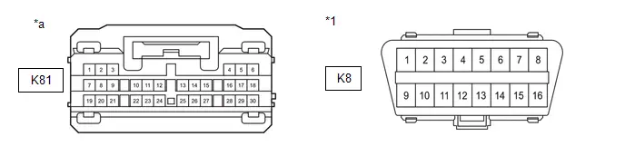
| *1 | DLC3 | - | - |
| *a | Front view of wire harness connector (to Radio and Display Receiver Assembly) | - | - |
Standard Resistance:
| Terminal No. (Symbol) | Terminal Description | Condition | Specified Condition |
|---|---|---|---|
| K81-13 (CANH) - K81-14 (CANL) | HIGH-level CAN bus line - LOW-level CAN bus line | Cable disconnected from negative (-) auxiliary battery terminal | 54 to 69 Ω |
| K81-13 (CANH) - K8-4 (CG) | HIGH-level CAN bus line - Ground | Cable disconnected from negative (-) auxiliary battery terminal | 200 Ω or higher |
| K81-14 (CANL) - K8-4 (CG) | LOW-level CAN bus line - Ground | Cable disconnected from negative (-) auxiliary battery terminal | 200 Ω or higher |
| K81-13 (CANH) - K8-16 (BAT) | HIGH-level CAN bus line - Auxiliary battery positive ( ) | Cable disconnected from negative (-) auxiliary battery terminal | 6 kΩ or higher |
| K81-14 (CANL) - K8-16 (BAT) | LOW-level CAN bus line - Auxiliary battery positive ( ) | Cable disconnected from negative (-) auxiliary battery terminal | 6 kΩ or higher |
BATTERY ECU ASSEMBLY
Refer to Terminals of ECU.
-
for M20A-FXS:
Click here

-
for 2ZR-FXE:
Click here

(a) Disconnect the cable from the negative (-) auxiliary battery terminal.
(b) Disconnect the R40 battery ECU assembly connector.
(c) Measure the resistance according to the value(s) in the table below.
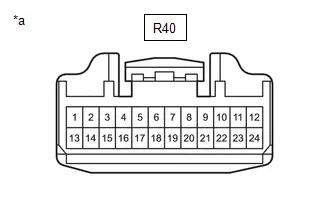
| *a | Front view of wire harness connector (to Battery ECU Assembly) |
Standard Resistance:
Bus 2 Main Lines| Terminal No. (Symbol) | Terminal Description | Condition | Specified Condition |
|---|---|---|---|
| R40-9 (CA2H) - R40-8 (CA2L) | HIGH-level CAN bus line - LOW-level CAN bus line | Cable disconnected from negative (-) auxiliary battery terminal | 108 to 132 Ω |
| R40-9 (CA2H) - R40-10 (GND) | HIGH-level CAN bus line - Ground | Cable disconnected from negative (-) auxiliary battery terminal | 200 Ω or higher |
| R40-8 (CA2L) - R40-10 (GND) | LOW-level CAN bus line - Ground | Cable disconnected from negative (-) auxiliary battery terminal | 200 Ω or higher |
| R40-9 (CA2H) - R40-24 (AM) | HIGH-level CAN bus line - Auxiliary battery positive ( ) | Cable disconnected from negative (-) auxiliary battery terminal | 6 kΩ or higher |
| R40-8 (CA2L) - R40-24 (AM) | LOW-level CAN bus line - Auxiliary battery positive ( ) | Cable disconnected from negative (-) auxiliary battery terminal | 6 kΩ or higher |
| R40-20 (C2HB) - R40-19 (C2LB) | HIGH-level CAN bus line - LOW-level CAN bus line | Cable disconnected from negative (-) auxiliary battery terminal | 108 to 132 Ω |
| R40-20 (C2HB) - R40-10 (GND) | HIGH-level CAN bus line - Ground | Cable disconnected from negative (-) auxiliary battery terminal | 200 Ω or higher |
| R40-19 (C2LB) - R40-10 (GND) | LOW-level CAN bus line - Ground | Cable disconnected from negative (-) auxiliary battery terminal | 200 Ω or higher |
| R40-20 (C2HB) - R40-24 (AM) | HIGH-level CAN bus line - Auxiliary battery positive ( ) | Cable disconnected from negative (-) auxiliary battery terminal | 6 kΩ or higher |
| R40-19 (C2LB) - R40-24 (AM) | LOW-level CAN bus line - Auxiliary battery positive ( ) | Cable disconnected from negative (-) auxiliary battery terminal | 6 kΩ or higher |
| Terminal No. (Symbol) | Terminal Description | Condition | Specified Condition |
|---|---|---|---|
| R40-22 (CA1H) - R40-21 (CA1L) | HIGH-level CAN bus line - LOW-level CAN bus line | Cable disconnected from negative (-) auxiliary battery terminal | 108 to 132 Ω |
| R40-22 (CA1H) - R40-10 (GND) | HIGH-level CAN bus line - Ground | Cable disconnected from negative (-) auxiliary battery terminal | 200 Ω or higher |
| R40-21 (CA1L) - R40-10 (GND) | LOW-level CAN bus line - Ground | Cable disconnected from negative (-) auxiliary battery terminal | 200 Ω or higher |
| R40-22 (CA1H) - R40-24 (AM) | HIGH-level CAN bus line - Auxiliary battery positive ( ) | Cable disconnected from negative (-) auxiliary battery terminal | 6 kΩ or higher |
| R40-21 (CA1L) - R40-24 (AM) | LOW-level CAN bus line - Auxiliary battery positive ( ) | Cable disconnected from negative (-) auxiliary battery terminal | 6 kΩ or higher |
CLEARANCE WARNING ECU ASSEMBLY (w/ Intuitive Parking Assist System)
Refer to Terminals of ECU.
Click here

(a) Disconnect the cable from the negative (-) auxiliary battery terminal.
(b) Disconnect the R36 clearance warning ECU assembly connector.
(c) Measure the resistance according to the value(s) in the table below.
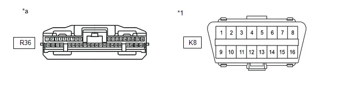
| *1 | DLC3 | - | - |
| *a | Front view of wire harness connector (to Clearance Warning ECU Assembly) | - | - |
Standard Resistance:
| Terminal No. (Symbol) | Terminal Description | Condition | Specified Condition |
|---|---|---|---|
| R36-17 (R1) - R36-18 (R2) | HIGH-level CAN bus line - LOW-level CAN bus line | Cable disconnected from negative (-) auxiliary battery terminal | 54 to 69 Ω |
| R36-17 (R1) - R36-31 (E) | HIGH-level CAN bus line - Ground | Cable disconnected from negative (-) auxiliary battery terminal | 200 Ω or higher |
| R36-18 (R2) - R36-31 (E) | LOW-level CAN bus line - Ground | Cable disconnected from negative (-) auxiliary battery terminal | 200 Ω or higher |
| R36-17 (R1) - K8-16 (BAT) | HIGH-level CAN bus line - Auxiliary battery positive ( ) | Cable disconnected from negative (-) auxiliary battery terminal | 6 kΩ or higher |
| R36-18 (R2) - K8-16 (BAT) | LOW-level CAN bus line - Auxiliary battery positive ( ) | Cable disconnected from negative (-) auxiliary battery terminal | 6 kΩ or higher |
POSITION CONTROL ECU ASSEMBLY LH (w/ Seat Position Memory System)
Refer to Terminals of ECU.
Click here

(a) Disconnect the cable from the negative (-) auxiliary battery terminal.
(b) Disconnect the b11 and b13 position control ECU assembly LH connectors.
(c) Measure the resistance according to the value(s) in the table below.
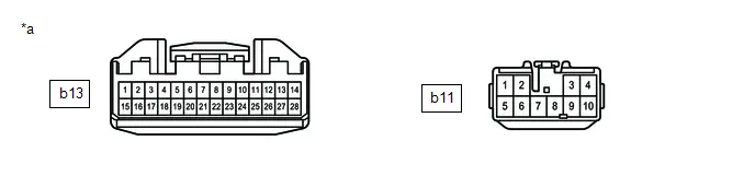
| *a | Front view of wire harness connector (to Position Control ECU Assembly LH) | - | - |
Standard Resistance:
| Terminal No. (Symbol) | Terminal Description | Condition | Specified Condition |
|---|---|---|---|
| b13-13 (CANP) - b13-14 (CANN) | HIGH-level CAN bus line - LOW-level CAN bus line | Cable disconnected from negative (-) auxiliary battery terminal | 54 to 69 Ω |
| b13-13 (CANP) - b11-2 (GND) | HIGH-level CAN bus line - Ground | Cable disconnected from negative (-) auxiliary battery terminal | 200 Ω or higher |
| b13-14 (CANN) - b11-2 (GND) | LOW-level CAN bus line - Ground | Cable disconnected from negative (-) auxiliary battery terminal | 200 Ω or higher |
| b13-13 (CANP) - b11-3 ( B) | HIGH-level CAN bus line - Auxiliary battery positive ( ) | Cable disconnected from negative (-) auxiliary battery terminal | 6 kΩ or higher |
| b13-14 (CANN) - b11-3 ( B) | LOW-level CAN bus line - Auxiliary battery positive ( ) | Cable disconnected from negative (-) auxiliary battery terminal | 6 kΩ or higher |
TIRE PRESSURE WARNING ECU AND RECEIVER
Refer to Terminals of ECU.
Click here

(a) Disconnect the cable from the negative (-) auxiliary battery terminal.
(b) Disconnect the R31 tire pressure warning ECU and receiver connector.
(c) Measure the resistance according to the value(s) in the table below.
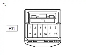
| *a | Front view of wire harness connector (to Tire Pressure Warning ECU and Receiver) |
Standard Resistance:
| Terminal No. (Symbol) | Terminal Description | Condition | Specified Condition |
|---|---|---|---|
| R31-9 (CANH) - R31-10 (CANL) | HIGH-level CAN bus line - LOW-level CAN bus line | Cable disconnected from negative (-) auxiliary battery terminal | 54 to 69 Ω |
| R31-9 (CANH) - R31-12 (GND) | HIGH-level CAN bus line - Ground | Cable disconnected from negative (-) auxiliary battery terminal | 200 Ω or higher |
| R31-10 (CANL) - R31-12 (GND) | LOW-level CAN bus line - Ground | Cable disconnected from negative (-) auxiliary battery terminal | 200 Ω or higher |
| R31-9 (CANH) - R31-7 ( B) | HIGH-level CAN bus line - Auxiliary battery positive ( ) | Cable disconnected from negative (-) auxiliary battery terminal | 6 kΩ or higher |
| R31-10 (CANL) - R31-7 ( B) | LOW-level CAN bus line - Auxiliary battery positive ( ) | Cable disconnected from negative (-) auxiliary battery terminal | 6 kΩ or higher |
TRANSMISSION FLOOR SHIFT ASSEMBLY
Refer to Terminals of ECU.
Click here

(a) Disconnect the cable from the negative (-) auxiliary battery terminal.
(b) Disconnect the K53 transmission floor shift assembly connector.
(c) Measure the resistance according to the value(s) in the table below.
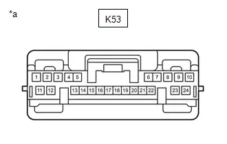
| *a | Front view of wire harness connector (to Transmission Floor Shift Assembly) |
Standard Resistance:
Bus 2 Branch Lines| Terminal No. (Symbol) | Terminal Description | Condition | Specified Condition |
|---|---|---|---|
| K53-15 (CA1H) - K53-16 (CA1L) | HIGH-level CAN bus line - LOW-level CAN bus line | Cable disconnected from negative (-) auxiliary battery terminal | 54 to 69 Ω |
| K53-15 (CA1H) - K53-9 (E1) | HIGH-level CAN bus line - Ground | Cable disconnected from negative (-) auxiliary battery terminal | 200 Ω or higher |
| K53-16 (CA1L) - K53-9 (E1) | LOW-level CAN bus line - Ground | Cable disconnected from negative (-) auxiliary battery terminal | 200 Ω or higher |
| K53-15 (CA1H) - K53-2 (BATT) | HIGH-level CAN bus line - Auxiliary battery positive ( ) | Cable disconnected from negative (-) auxiliary battery terminal | 6 kΩ or higher |
| K53-16 (CA1L) - K53-2 (BATT) | LOW-level CAN bus line - Auxiliary battery positive ( ) | Cable disconnected from negative (-) auxiliary battery terminal | 6 kΩ or higher |
| Terminal No. (Symbol) | Terminal Description | Condition | Specified Condition |
|---|---|---|---|
| K53-21 (CA3H) - K53-6 (CA3L) | HIGH-level CAN bus line - LOW-level CAN bus line | Cable disconnected from negative (-) auxiliary battery terminal | 54 to 69 Ω |
| K53-21 (CA3H) - K53-9 (E1) | HIGH-level CAN bus line - Ground | Cable disconnected from negative (-) auxiliary battery terminal | 200 Ω or higher |
| K53-6 (CA3L) - K53-9 (E1) | LOW-level CAN bus line - Ground | Cable disconnected from negative (-) auxiliary battery terminal | 200 Ω or higher |
| K53-21 (CA3H) - K53-2 (BATT) | HIGH-level CAN bus line - Auxiliary battery positive ( ) | Cable disconnected from negative (-) auxiliary battery terminal | 6 kΩ or higher |
| K53-6 (CA3L) - K53-2 (BATT) | LOW-level CAN bus line - Auxiliary battery positive ( ) | Cable disconnected from negative (-) auxiliary battery terminal | 6 kΩ or higher |
SHIFT CONTROL ACTUATOR ASSEMBLY
Refer to Terminals of ECU.
Click here

(a) Disconnect the cable from the negative (-) auxiliary battery terminal.
(b) Disconnect the C49 shift control actuator assembly connector.
(c) Measure the resistance according to the value(s) in the table below.
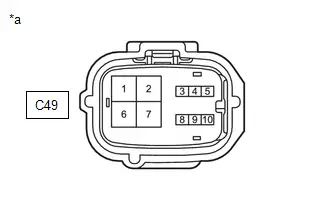
| *a | Front view of wire harness connector (to Shift Control Actuator Assembly) |
Standard Resistance:
| Terminal No. (Symbol) | Terminal Description | Condition | Specified Condition |
|---|---|---|---|
| C49-4 (CA3H) - C49-3 (CA3L) | HIGH-level CAN bus line - LOW-level CAN bus line | Cable disconnected from negative (-) auxiliary battery terminal | 54 to 69 Ω |
| C49-4 (CA3H) - C49-2 (E01) | HIGH-level CAN bus line - Ground | Cable disconnected from negative (-) auxiliary battery terminal | 200 Ω or higher |
| C49-3 (CA3L) - C49-2 (E01) | LOW-level CAN bus line - Ground | Cable disconnected from negative (-) auxiliary battery terminal | 200 Ω or higher |
| C49-4 (CA3H) - C49-1 (MA1) | HIGH-level CAN bus line - Auxiliary battery positive ( ) | Cable disconnected from negative (-) auxiliary battery terminal | 6 kΩ or higher |
| C49-3 (CA3L) - C49-1 (MA1) | LOW-level CAN bus line - Auxiliary battery positive ( ) | Cable disconnected from negative (-) auxiliary battery terminal | 6 kΩ or higher |
INTEGRATION CONTROL SUPPLY
Refer to Terminals of ECU.
Click here

(a) Disconnect the cable from the negative (-) auxiliary battery terminal.
(b) Disconnect the K26 integration control supply connector.
(c) Measure the resistance according to the value(s) in the table below.
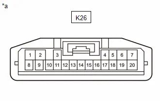
| *a | Front view of wire harness connector (to Integration Control Supply) |
Standard Resistance:
| Terminal No. (Symbol) | Terminal Description | Condition | Specified Condition |
|---|---|---|---|
| K26-3 (CANH) - K26-11 (CANL) | HIGH-level CAN bus line - LOW-level CAN bus line | Cable disconnected from negative (-) auxiliary battery terminal | 54 to 69 Ω |
| K26-3 (CANH) - K26-2 (GND) | HIGH-level CAN bus line - Ground | Cable disconnected from negative (-) auxiliary battery terminal | 200 Ω or higher |
| K26-11 (CANL) - K26-2 (GND) | LOW-level CAN bus line - Ground | Cable disconnected from negative (-) auxiliary battery terminal | 200 Ω or higher |
| K26-3 (CANH) - K26-7 ( B) | HIGH-level CAN bus line - Auxiliary battery positive ( ) | Cable disconnected from negative (-) auxiliary battery terminal | 6 kΩ or higher |
| K26-11 (CANL) - K26-7 ( B) | LOW-level CAN bus line - Auxiliary battery positive ( ) | Cable disconnected from negative (-) auxiliary battery terminal | 6 kΩ or higher |
INNER REAR VIEW MIRROR ASSEMBLY (w/ Digital Inner Mirror System)
Refer to Terminals of ECU.
Click here

(a) Disconnect the cable from the negative (-) auxiliary battery terminal.
(b) Disconnect the U12 inner rear view mirror assembly connector.
(c) Measure the resistance according to the value(s) in the table below.
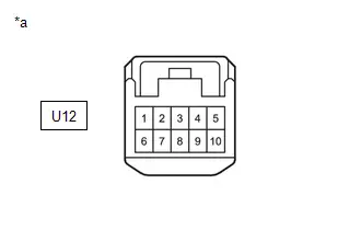
| *a | Front view of wire harness connector (to Inner Rear View Mirror Assembly) |
Standard Resistance:
| Terminal No. (Symbol) | Terminal Description | Condition | Specified Condition |
|---|---|---|---|
| U12-9 (CANH) - U12-10 (CANL) | HIGH-level CAN bus line - LOW-level CAN bus line | Cable disconnected from negative (-) auxiliary battery terminal | 54 to 69 Ω |
| U12-9 (CANH) - U12-2 (E) | HIGH-level CAN bus line - Ground | Cable disconnected from negative (-) auxiliary battery terminal | 200 Ω or higher |
| U12-10 (CANL) - U12-2 (E) | LOW-level CAN bus line - Ground | Cable disconnected from negative (-) auxiliary battery terminal | 200 Ω or higher |
| U12-9 (CANH) - U12-6 ( B) | HIGH-level CAN bus line - Auxiliary battery positive ( ) | Cable disconnected from negative (-) auxiliary battery terminal | 6 kΩ or higher |
| U12-10 (CANL) - U12-6 ( B) | LOW-level CAN bus line - Auxiliary battery positive ( ) | Cable disconnected from negative (-) auxiliary battery terminal | 6 kΩ or higher |
FRONT SIDE RADAR SENSOR (A) (w/ Front Side Radar Sensor System)
Refer to Terminals of ECU.
Click here

(a) Disconnect the cable from the negative (-) auxiliary battery terminal.
(b) Disconnect the A41 front side radar sensor (A) connector.
(c) Measure the resistance according to the value(s) in the table below.
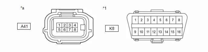
| *1 | DLC3 | - | - |
| *a | Front view of wire harness connector (to Front Side Radar Sensor (A)) | - | - |
Standard Resistance:
| Terminal No. (Symbol) | Terminal Description | Condition | Specified Condition |
|---|---|---|---|
| A41-3 (CA1P) - A41-2 (CA1N) | HIGH-level CAN bus line - LOW-level CAN bus line | Cable disconnected from negative (-) auxiliary battery terminal | 54 to 69 Ω |
| A41-3 (CA1P) - A41-1 (FMGD) | HIGH-level CAN bus line - Ground | Cable disconnected from negative (-) auxiliary battery terminal | 200 Ω or higher |
| A41-2 (CA1N) - A41-1 (FMGD) | LOW-level CAN bus line - Ground | Cable disconnected from negative (-) auxiliary battery terminal | 200 Ω or higher |
| A41-3 (CA1P) - K8-16 (BAT) | HIGH-level CAN bus line - Auxiliary battery positive ( ) | Cable disconnected from negative (-) auxiliary battery terminal | 6 kΩ or higher |
| A41-2 (CA1N) - K8-16 (BAT) | LOW-level CAN bus line - Auxiliary battery positive ( ) | Cable disconnected from negative (-) auxiliary battery terminal | 6 kΩ or higher |
REAR TELEVISION CAMERA ASSEMBLY (w/ Parking Assist Monitor System (w/ Parking Support Brake System))
Refer to Terminals of ECU.
Click here

(a) Disconnect the cable from the negative (-) auxiliary battery terminal.
(b) Disconnect the V3 rear television camera assembly connector.
(c) Measure the resistance according to the value(s) in the table below.
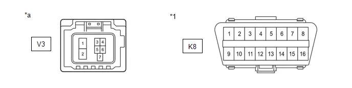
| *1 | DLC3 | - | - |
| *a | Front view of wire harness connector (to Rear Television Camera Assembly) | - | - |
Standard Resistance:
| Terminal No. (Symbol) | Terminal Description | Condition | Specified Condition |
|---|---|---|---|
| V3-1 (CANH) - V3-2 (CANL) | HIGH-level CAN bus line - LOW-level CAN bus line | Cable disconnected from negative (-) auxiliary battery terminal | 54 to 69 Ω |
| V3-1 (CANH) - K8-4 (CG) | HIGH-level CAN bus line - Ground | Cable disconnected from negative (-) auxiliary battery terminal | 200 Ω or higher |
| V3-2 (CANL) - K8-4 (CG) | LOW-level CAN bus line - Ground | Cable disconnected from negative (-) auxiliary battery terminal | 200 Ω or higher |
| V3-1 (CANH) - K8-16 (BAT) | HIGH-level CAN bus line - Auxiliary battery positive ( ) | Cable disconnected from negative (-) auxiliary battery terminal | 6 kΩ or higher |
| V3-2 (CANL) - K8-16 (BAT) | LOW-level CAN bus line - Auxiliary battery positive ( ) | Cable disconnected from negative (-) auxiliary battery terminal | 6 kΩ or higher |
REAR TELEVISION CAMERA ASSEMBLY (w/ Parking Assist Monitor System (w/o Parking Support Brake System))
Refer to Terminals of ECU.
Click here

(a) Disconnect the cable from the negative (-) auxiliary battery terminal.
(b) Disconnect the V2 rear television camera assembly connector.
(c) Measure the resistance according to the value(s) in the table below.
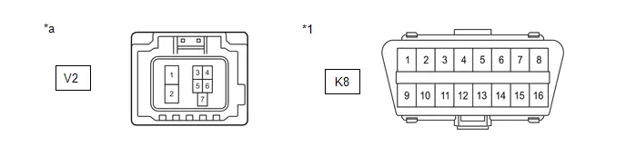
| *1 | DLC3 | - | - |
| *a | Front view of wire harness connector (to Rear Television Camera Assembly) | - | - |
Standard Resistance:
| Terminal No. (Symbol) | Terminal Description | Condition | Specified Condition |
|---|---|---|---|
| V2-1 (CANH) - V2-2 (CANL) | HIGH-level CAN bus line - LOW-level CAN bus line | Cable disconnected from negative (-) auxiliary battery terminal | 54 to 69 Ω |
| V2-1 (CANH) - K8-4 (CG) | HIGH-level CAN bus line - Ground | Cable disconnected from negative (-) auxiliary battery terminal | 200 Ω or higher |
| V2-2 (CANL) - K8-4 (CG) | LOW-level CAN bus line - Ground | Cable disconnected from negative (-) auxiliary battery terminal | 200 Ω or higher |
| V2-1 (CANH) - K8-16 (BAT) | HIGH-level CAN bus line - Auxiliary battery positive ( ) | Cable disconnected from negative (-) auxiliary battery terminal | 6 kΩ or higher |
| V2-2 (CANL) - K8-16 (BAT) | LOW-level CAN bus line - Auxiliary battery positive ( ) | Cable disconnected from negative (-) auxiliary battery terminal | 6 kΩ or higher |
MULTIPLEX NETWORK DOOR ECU (w/ Power Back Door System)
Refer to Terminals of ECU.
Click here

(a) Disconnect the cable from the negative (-) auxiliary battery terminal.
(b) Disconnect the W13 multiplex network door ECU connector.
(c) Measure the resistance according to the value(s) in the table below.
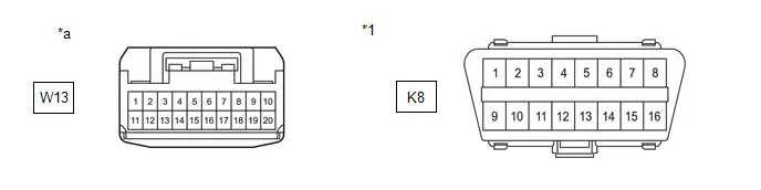
| *1 | DLC3 | - | - |
| *a | Front view of wire harness connector (to Multiplex Network Door ECU) | - | - |
Standard Resistance:
| Terminal No. (Symbol) | Terminal Description | Condition | Specified Condition |
|---|---|---|---|
| W13-10 (CANP) - W13-20 (CANN) | HIGH-level CAN bus line - LOW-level CAN bus line | Cable disconnected from negative (-) auxiliary battery terminal | 54 to 69 Ω |
| W13-10 (CANP) - K8-4 (CG) | HIGH-level CAN bus line - Ground | Cable disconnected from negative (-) auxiliary battery terminal | 200 Ω or higher |
| W13-20 (CANN) - K8-4 (CG) | LOW-level CAN bus line - Ground | Cable disconnected from negative (-) auxiliary battery terminal | 200 Ω or higher |
| W13-10 (CANP) - K8-16 (BAT) | HIGH-level CAN bus line - Auxiliary battery positive ( ) | Cable disconnected from negative (-) auxiliary battery terminal | 6 kΩ or higher |
| W13-20 (CANN) - K8-16 (BAT) | LOW-level CAN bus line - Auxiliary battery positive ( ) | Cable disconnected from negative (-) auxiliary battery terminal | 6 kΩ or higher |
PARKING ASSIST ECU (w/ Panoramic View Monitor System)
Refer to Terminals of ECU.
Click here

(a) Disconnect the cable from the negative (-) auxiliary battery terminal.
(b) Disconnect the R34 parking assist ECU connector.
(c) Measure the resistance according to the value(s) in the table below.
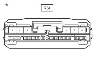
| *a | Front view of wire harness connector (to Parking Assist ECU) |
Standard Resistance:
| Terminal No. (Symbol) | Terminal Description | Condition | Specified Condition |
|---|---|---|---|
| R34-12 (CANH) - R34-13 (CANL) | HIGH-level CAN bus line - LOW-level CAN bus line | Cable disconnected from negative (-) auxiliary battery terminal | 54 to 69 Ω |
| R34-12 (CANH) - R34-4 (GND1) | HIGH-level CAN bus line - Ground | Cable disconnected from negative (-) auxiliary battery terminal | 200 Ω or higher |
| R34-13 (CANL) - R34-4 (GND1) | LOW-level CAN bus line - Ground | Cable disconnected from negative (-) auxiliary battery terminal | 200 Ω or higher |
| R34-12 (CANH) - R34-1 ( B) | HIGH-level CAN bus line - Auxiliary battery positive ( ) | Cable disconnected from negative (-) auxiliary battery terminal | 6 kΩ or higher |
| R34-13 (CANL) - R34-1 ( B) | LOW-level CAN bus line - Auxiliary battery positive ( ) | Cable disconnected from negative (-) auxiliary battery terminal | 6 kΩ or higher |
Diagnosis System
DIAGNOSIS SYSTEM
NOTICE:
The following communication bus check screen is provided only as an example. This screen differs from the actual screen for this vehicle.
Description of "Communication Bus Check" Screen
HINT:
The ECUs and sensors that are normally connected to the CAN communication system are displayed on the GTS.
(a) Select "Communication Bus Check" on the menu screen of the GTS.
CAN Bus CheckHINT:
If items are not selected correctly in the Toyota Prius vehicle specification pop up screen, the name of the CAN junction connector to which the ECUs or sensors are connected may not be displayed on the "Communication Bus Check" screen.
(b) Confirm that the "Communication Bus Check" screen is displayed and the ECUs and sensors that have a history of being connected to the monitoring ECU are displayed.
HINT:
- Even if an ECU or sensor that is connected to a bus that is monitored by a bus monitoring ECU (gateway function equipped ECU) is not communicating, it will remain displayed on the "Communication Bus Check" screen.
- When an ECU or sensor that is connected to a bus that is not monitored by a bus monitoring ECU (gateway function equipped ECU) is not displayed on the "Communication Bus Check" screen, it means that it is not communicating.
- ECUs with a history of being connected are displayed even if the ECUs are removed.
(c) The default display setting selected on the combo box is ALL. When checking for ECUs or sensors for a specific bus, choose the bus from the drop down list. ALL, each bus, each sub bus and Central Gateway are listed in the drop down list.
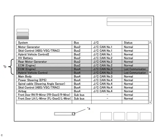
| *a | Combo box | *b | Background color is red or yellow |
| Item | Detail |
|---|---|
| Combo box: ALL | Displays all ECUs and sensors connected to the central bus and sub buses. |
| Combo box: Bus | Displays ECUs and sensors connected to the selected bus. |
| Combo box: Sub bus | Displays ECUs and sensors connected to the selected sub bus. |
| Combo box: Central Gateway | Displays all ECUs and sensors connected to the central bus. |
NOTICE:
- When using the combo box, it may be possible to select a sub bus from the drop down list that does not have any connected ECUs or sensors. This is not a malfunction and occurs when there is no optional device connected to a sub bus which is monitored by a sub bus monitoring ECU (gateway function equipped ECU).
-
In the drop down list, all sub buses applicable to the model are displayed (e.g. LIN communication sub buses are also displayed). For information on sub buses necessary to diagnose the CAN communication system, refer to System Diagram.
Click here

HINT:
The background color of an ECU or sensor changes according to its connection status as indicated in the following table.
Description of "Communication Bus Check" Screen| Bus Type | Background Color | Connection Status |
|---|---|---|
| Bus | White | Communication has been normal. |
| Yellow | Communication stop occurred at least once since the start of the CAN bus check, but communication is currently occurring (unstable communication). | |
| Red | Currently not communicating (either of the following):
| |
| Not displayed | Either of the following:
| |
| Sub bus with a gateway function equipped ECU that does not memorize connected ECUs or sensors*2 | White | Communication has been normal since the start of the CAN bus check. |
| Yellow | Communication stop occurred at least once since the start of the CAN bus check, but communication is currently occurring (unstable communication). | |
| Red | Communication occurred at least once since the start of the CAN bus check, but is currently not occurring. | |
| Not displayed | Communication stop has continued since the start of the CAN bus check.*1 | |
| Sub bus with a gateway function equipped ECU that memorizes connected ECUs and sensors*3 | White | Communication has been normal. |
| Yellow | Communication stop occurred at least once since the start of the CAN bus check, but communication is currently occurring (unstable communication). | |
| Red | Currently not communicating (either of the following):
| |
| Not displayed | Either of the following:
|
- Gateway function equipped ECUs relay signals between ECUs and sensors connected to different buses.
- *1: An ECU or sensor is installed to the Toyota Prius vehicle but is not displayed on the "Communication Bus Check" screen.
- *2: The gateway function equipped ECU does not memorize ECUs and sensors connected to its respective sub bus.
- *3: The gateway function equipped ECU memorizes ECUs and sensors connected to its respective sub bus.
- *4: When the central gateway ECU (network gateway ECU) has an internal malfunction or cannot communicate with the GTS, the name of buses, sub buses, ECUs and sensors will not be displayed.
- *5: When no ECUs or sensors are connected to a bus, the message "There is no system found on the communication Bus." will be displayed.
- *6: When a gateway function equipped ECU cannot communicate with the central gateway ECU (network gateway ECU), the name of sub buses and ECUs or sensors connected to the sub bus will not be displayed.
- *7: When no ECUs or sensors are connected to the sub bus, the message "There is no system found on the communication Bus." will be displayed.
- If there is no communication between the GTS and the Toyota Prius vehicle, or no ECUs or sensors are displayed as connected, check the central gateway ECU (network gateway ECU) and diagnosis bus (The bus that connects the DLC3 to the central gateway ECU (network gateway ECU)) for malfunctions.
(d) Monitor the screen for any ECU or sensor connection status changes for a period of 2 minutes.
HINT:
- If an open occurs in one of the wires of a CAN branch line, it may interfere with the communication of other ECUs or sensors resulting in an incorrect state being displayed.
- If the connection status changes intermittently during the inspection, repair the open in the branch line of the ECU or sensor that is not communicating, and then perform Communication Bus Check again.
NOTICE:
The following communication bus check screen is provided only as an example. This screen differs from the actual screen for this Toyota Prius vehicle.
Description of "Communication Bus Check (Detail)" Screen
HINT:
The communication error history of ECUs or sensors which have communication error history can be displayed on the "Communication Bus Check (Detail)" screen.
(a) Select "Communication Bus Check" on the menu screen of the GTS.
CAN Bus CheckHINT:
If items are not selected correctly in the Toyota Prius vehicle specification pop up screen, the name of the CAN junction connector to which the ECUs or sensors are connected may not be displayed on the "Communication Bus Check" screen.
(b) Select "Detail" on the "Communication Bus Check" screen.

| *a | Communication Bus Check (Detail) | - | - |
(c) Confirm that the "Communication Bus Check (Detail)" screen is displayed and the communication error history of the ECUs or sensors up to present is displayed.
HINT:
- Lost Communication Time and Lost Communication Trip are only displayed for the central bus.
- Lost Communication Time and Lost Communication Trip are not displayed for sub buses.
(d) The default display setting selected on the combo box is ALL. When checking for ECUs or sensors for a specific bus, choose the bus from the drop down list. ALL, each bus, each sub bus and Central Gateway are listed in the drop down list.
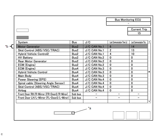
| *a | Combo box | *b | Background color is red |
| Item | Detail |
|---|---|
| Combo box: ALL | Displays all ECUs and sensors connected to the central bus and sub buses. |
| Combo box: Bus | Displays ECUs and sensors connected to the selected bus. |
| Combo box: Sub bus | Displays ECUs and sensors connected to the selected sub bus. |
| Combo box: Central Gateway | Displays all ECUs and sensors connected to the central bus. |
| Bus Monitoring ECU | Displays the gateway function equipped ECU which monitors the selected bus or sub bus. |
| Current Trip | Displays the total number of trips up to now* |
| Lost Communication Time(s) | Displays the longest period of time in seconds that the ECU or sensor connected to the central bus was not communicating. |
| Lost Communication Trip | Displays the trip in which the longest period of time that the ECU or sensor connected to the central bus was not communicating occurred. |
- *: If the component has been replaced with a new one, the total number of trips after the replacement is displayed.
NOTICE:
- The Lost Communication Time column displays the longest period of time in seconds that the central gateway ECU (network gateway ECU) detected a communication stop in the respective ECU or sensor.
- The Lost Communication Trip column displays the trip in which the central gateway ECU (network gateway ECU) detected the longest communication stop in the respective ECU or sensor.
- When using the combo box, it may be possible to select a sub bus from the drop down list that does not have any connected ECUs or sensors. This is not a malfunction and occurs when there is no optional device connected to a sub bus which is monitored by a sub bus monitoring ECU (gateway function equipped ECU).
-
In the drop down list, all sub buses applicable to the model are displayed (e.g. LIN communication sub buses are also displayed). For information on sub buses necessary to diagnose CAN communication system, refer to the System Diagram.
Click here

HINT:
The background color of an ECU or sensor changes according to its connection status as indicated in the following table.
Description of "Communication Bus Check (Detail)" Screen| Bus Type | Background Color | Connection Status |
|---|---|---|
| Bus | White | Either of the following:
|
| Red | Lost Communication Time is 6 seconds or more. | |
| Not displayed | Either of the following:
| |
| Sub bus | White | Lost Communication Time is displayed as "-". |
| Not displayed | Either of the following:
|
- If there is no communication between the GTS and the Toyota Prius vehicle, or no ECUs or sensors are displayed as connected, check the central gateway ECU (network gateway ECU) and diagnosis bus (The bus that connects the DLC3 to the central gateway ECU (network gateway ECU)) for malfunctions.
- Lost Communication Time and Lost Communication Trip are not displayed for sub buses.
- *1: When the central gateway ECU (network gateway ECU) has an internal malfunction or cannot communicate with the GTS, the name of buses, sub buses, ECUs and sensors will not be displayed.
- *2: When no ECUs or sensors are connected to a bus, the message "There is no system found on the communication Bus." will be displayed.
- *3: When a gateway function equipped ECU cannot communicate with the central gateway ECU (network gateway ECU), the name of sub buses and ECUs or sensors connected to the sub bus will not be displayed.
- *4: When no ECUs or sensors are connected to the sub bus, the message "There is no system found on the communication Bus." will be displayed.
Communication Bus Check (Communication Malfunction Check)
HINT:
DTCs related to CAN communication are displayed for each ECU on the GTS.
(a) Select "Communication Bus Check" on the menu screen of the GTS.
CAN Bus Check(b) Select "Communication Malfunction Check" on the "Communication Bus Check" screen.
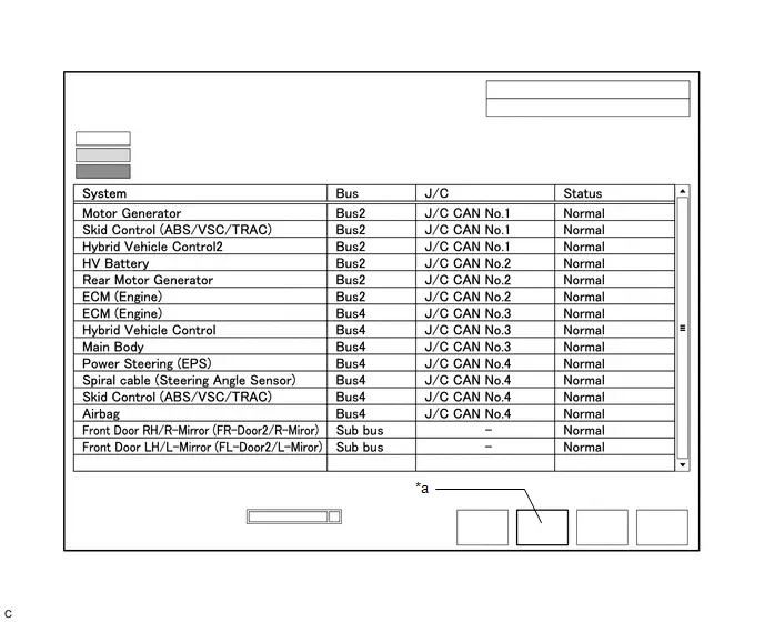
| *a | Communication Malfunction Check | - | - |
(c) Confirm that the "Communication Malfunction Check" screen is displayed and CAN communication DTCs for each ECU are displayed.
HINT:
When there are no CAN communication DTCs stored, no DTCs will be displayed.
How to Use "Communication Bus Check" Screen in Inspection
NOTICE:
The following CAN bus wiring diagram or communication bus check screen is provided only as an example. This wiring diagram or screen differs from the actual one for this Toyota Prius vehicle.
HINT:
- If the CAN communication system is currently malfunctioning, it is recommended to use Communication Bus Check rather than Communication DTCs for determining the suspected area.
- Turn the ignition switch to ON, or perform the necessary operations to reproduce the problem symptom, select "Communication Bus Check" and wait approximately 2 minutes. Check the communication status of each ECU or sensor on the screen while performing this operation.
(a) If the CAN communication system is currently malfunctioning, determine the suspected area using Communication Bus Check as follows:
Problem Symptoms Table| Problem Symptom Pattern | Display on Communication Bus Check Screen | Suspected Area |
|---|---|---|
| A | Almost all of the ECUs and sensors connected to the malfunctioning CAN bus are displayed as not communicating on the "Communication Bus Check" screen. |
|
| B | ECUs or sensors farther from the central gateway ECU (network gateway ECU) than the open in the wires are displayed as not communicating on the "Communication Bus Check" screen. | Open in both wires of a main bus line in the central bus |
| C | One ECU or sensor is displayed as not communicating on the "Communication Bus Check" screen. |
|
| D |
|
|
| E | One ECU or sensor is displayed as not communicating in multiple buses on the "Communication Bus Check" screen. |
|
| F | Some ECUs or sensors are displayed as not communicating in the central bus and other ECUs or sensors are displayed as not communicating in a sub bus. |
|
| G | A gateway function equipped ECU is displayed as not communicating in the central bus and ECUs and sensors connected to its respective sub bus are not displayed. |
|
| H | One ECU or sensor is displayed as not communicating in a sub bus on the "Communication Bus Check" screen. |
|
| I | ECUs or sensors farther from the sub bus monitoring ECU (gateway function equipped ECU) than the open in the wires are displayed as not communicating on the "Communication Bus Check" screen. | Open in both wires of a main bus line in a sub bus |
(b) Problem Symptom Pattern A
| Display on Communication Bus Check Screen | Almost all of the ECUs and sensors connected to the malfunctioning CAN bus are displayed as not communicating on the "Communication Bus Check" screen. |
| Details of Malfunction |
|
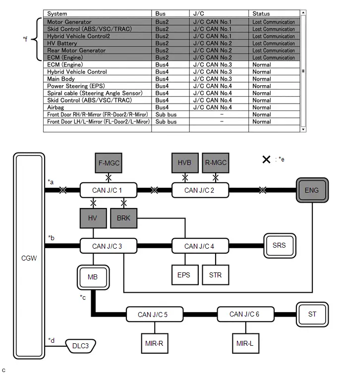
| *a | Bus 2 | *b | Bus 4 |
| *c | Sub bus | *d | Diagnosis bus |
| *e | Location of malfunction
| *f | Background color is red |
HINT:
- Due to the malfunction, almost all of the ECUs and sensors connected to Bus 2 will be displayed as not communicating and their background color will be red.
- The malfunction in Bus 2 will not affect the other buses.
- The malfunctioning part can be determined by inspecting for an open in the main bus line, a short between bus lines or a short to B or ground.
- Make sure to perform the inspection to measure resistances of buses to determine the cause of the malfunction.
| Display on Communication Bus Check Screen | Almost all of the ECUs and sensors connected to the malfunctioning CAN bus are displayed as not communicating on the "Communication Bus Check" screen. |
| Details of Malfunction |
|
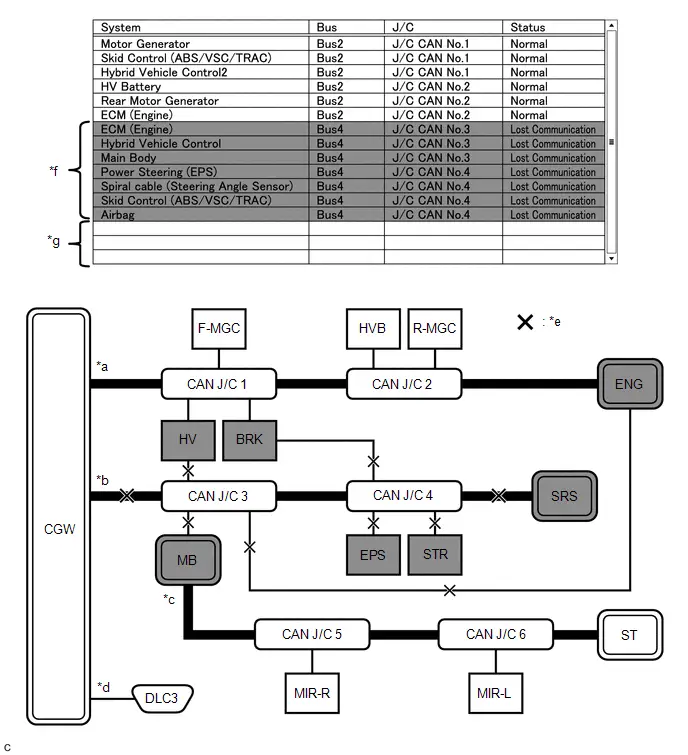
| *a | Bus 2 | *b | Bus 4 |
| *c | Sub bus | *d | Diagnosis bus |
| *e | Location of malfunction
| *f | Background color is red |
| *g | Not displayed | - | - |
HINT:
- Due to the malfunction, almost all of the ECUs and sensors connected to Bus 4 will be displayed as not communicating and their background color will be red.
- The malfunction will not affect the other buses of the central bus. However, the sub bus connected to Bus 4 is likely to be affected. The gateway function equipped ECU connected to Bus 4 will not communicate and consequently the sub bus and its respective ECUs or sensors monitored by the gateway function equipped ECU (sub bus monitoring ECU) will not be displayed, indicating that the gateway function equipped ECU is not communicating with the central gateway ECU (network gateway ECU).
- The malfunctioning part can be determined by inspecting for an open in the main bus line, a short between bus lines or a short to B or ground.
- Make sure to perform the inspection to measure resistances of buses to determine the cause of the malfunction.
(c) Problem Symptom Pattern B
| Display on Communication Bus Check Screen | ECUs or sensors farther from the central gateway ECU (network gateway ECU) than the open in the wires are displayed as not communicating on the "Communication Bus Check" screen. |
| Details of Malfunction | Open in both wires of the main bus line between CGW and No. 1 CAN junction connector in Bus 2 |

| *a | Bus 2 | *b | Bus 4 |
| *c | Sub bus | *d | Diagnosis bus |
| *e | Location of malfunction (open in both wires of the main bus line) | *f | Background color is red |
HINT:
- Due to the malfunction, almost all of the ECUs and sensors connected to Bus 2 will be displayed as not communicating and their background color will be red.
- The malfunction in Bus 2 will not affect the other buses.
- The malfunctioning part can be determined by inspecting for an open in the main bus line.
- Make sure to perform the inspection to measure resistances of buses to determine the cause of the malfunction.
| Display on Communication Bus Check Screen | ECUs or sensors farther from the central gateway ECU (network gateway ECU) than the open in the wires are displayed as not communicating on the "Communication Bus Check" screen. |
| Details of Malfunction | Open in both wires of the main bus line between the No. 1 CAN junction connector and No. 2 CAN junction connector in Bus 2 |
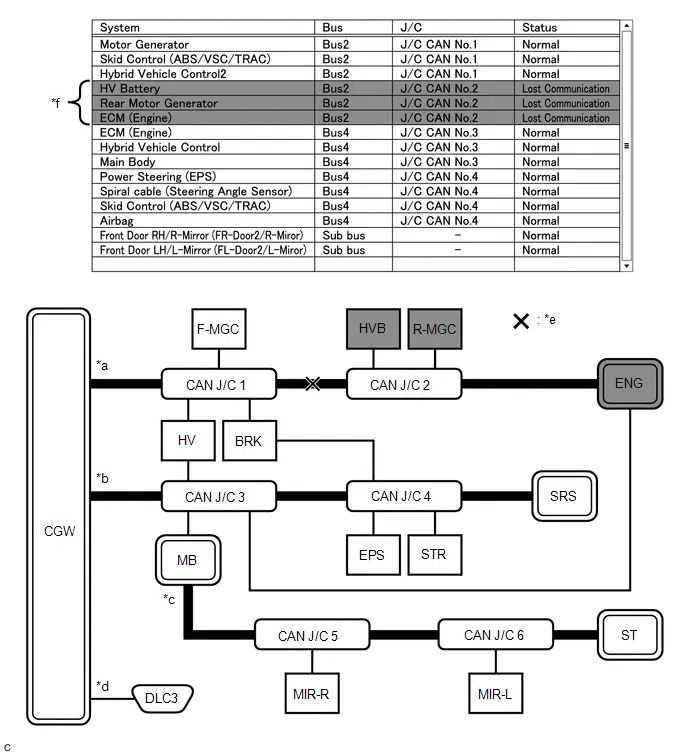
| *a | Bus 2 | *b | Bus 4 |
| *c | Sub bus | *d | Diagnosis bus |
| *e | Location of malfunction (open in both wires of the main bus line) | *f | Background color is red |
HINT:
- Due to the malfunction, ECUs or sensors farther from CGW than the open in the wires will be displayed as not communicating and their background color will be red.
- The malfunction in Bus 2 will not affect the other buses.
- The malfunctioning part can be determined by inspecting for an open in the main bus line.
- Make sure to perform the inspection to measure resistances of buses to determine the cause of the malfunction.
| Display on Communication Bus Check Screen | ECUs or sensors farther from the central gateway ECU (network gateway ECU) than the open in the wires are displayed as not communicating on the "Communication Bus Check" screen. |
| Details of Malfunction | Open in both wires of the main bus line between the No. 2 CAN junction connector and ENG in Bus 2 |
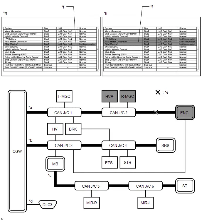
| *a | Bus 2 | *b | Bus 4 |
| *c | Sub bus | *d | Diagnosis bus |
| *e | Location of malfunction (open in both wires of the main bus line) | *f | Background color is red |
| *g | Pattern 1 | *h | Pattern 2 |
HINT:
- Even when the same part of the main bus line is open, depending on internal electrical noise which changes according to the position of the open in the line, the information displayed on the "Communication Bus Check" screen may differ.
- In pattern 2, the information displayed may be the same as when there is an open in both wires in the main bus line between the No. 1 CAN junction connector and No. 2 CAN junction connector, which may make it difficult to determine the malfunctioning part.
- The malfunction in Bus 2 will not affect the other buses.
- Make sure to perform the inspection to measure resistances of buses to determine the cause of the malfunction.
(d) Problem Symptom Pattern C
| Display on Communication Bus Check Screen | One ECU or sensor is displayed as not communicating on the "Communication Bus Check" screen. |
| Details of Malfunction |
|
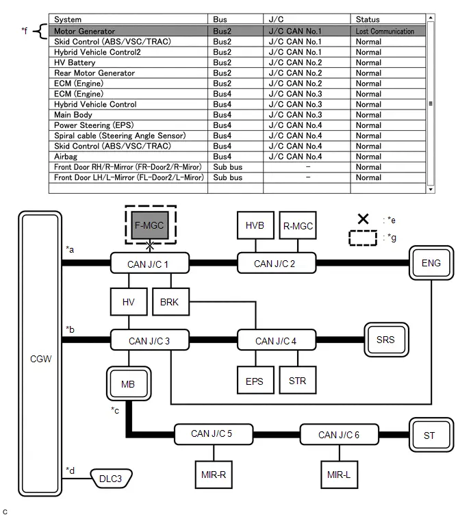
| *a | Bus 2 | *b | Bus 4 |
| *c | Sub bus | *d | Diagnosis bus |
| *e | Location of malfunction 1 (open in both wires of the branch line) | *f | Background color is red |
| *g | Location of malfunction 2
| - | - |
HINT:
The information displayed on the "Communication Bus Check" screen will be the same for an open in both wires of a branch line, an internal malfunction of an ECU or sensor or a malfunction in the power supplied to an ECU or sensor. In this example, the background color of the malfunctioning ECU or sensor will be red.
| Display on Communication Bus Check Screen | One ECU or sensor is displayed as not communicating on the "Communication Bus Check" screen. |
| Details of Malfunction | Open in both wires of the branch line connected to ENG in Bus 4 |
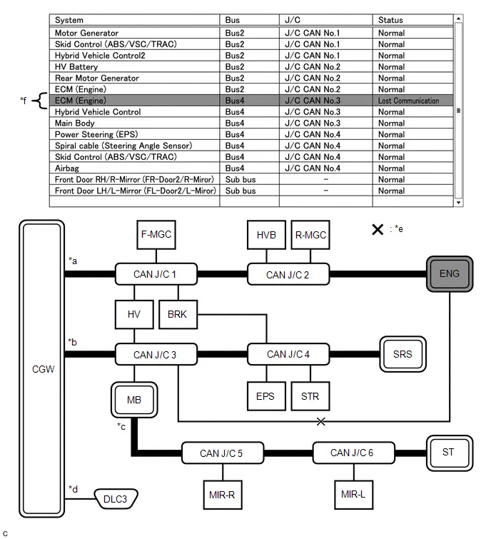
| *a | Bus 2 | *b | Bus 4 |
| *c | Sub bus | *d | Diagnosis bus |
| *e | Location of malfunction (open in both wires of the branch line) | *f | Background color is red |
HINT:
- The malfunction in Bus 4 will not affect the other buses.
- Due to the malfunction, although ENG is communicating normally with CGW via Bus 2, it is not communicating with CGW via Bus 4. Consequently, it will be displayed as not communicating in Bus 4.
(e) Problem Symptom Pattern D
| Display on Communication Bus Check Screen |
|
| Details of Malfunction |
|
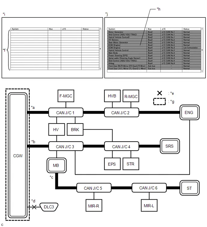
| *a | Bus 2 | *b | Bus 4 |
| *c | Sub bus | *d | Diagnosis bus |
| *e | Location of malfunction 1 (open in both wires of the branch line) | *f | Not displayed |
| *g | Location of malfunction 2 (Internal malfunction) | *h | Background color is red |
| *i | Pattern 1 (Malfunction occurred before CAN bus check) | *j | Pattern 2 (Malfunction occurred after CAN bus check) |
HINT:
When there is no communication between the GTS and the Toyota Prius vehicle, no ECUs or sensors will be displayed.
(f) Problem Symptom Pattern E
| Display on Communication Bus Check Screen | One ECU or sensor is displayed as not communicating in multiple buses on the "Communication Bus Check" screen. |
| Details of Malfunction |
|
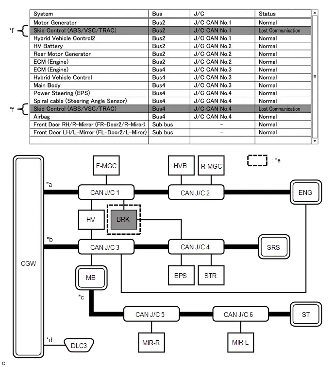
| *a | Bus 2 | *b | Bus 4 |
| *c | Sub bus | *d | Diagnosis bus |
| *e | Location of malfunction
| *f | Background color is red |
HINT:
The information displayed on the "Communication Bus Check" screen will be the same for an internal malfunction of an ECU or sensor, or a malfunction in the power supplied to an ECU or sensor.
Due to the malfunction, BRK is not communicating with CGW via both Bus 2 and Bus 4. Consequently, the background color of BRK will be red for both Bus 2 and Bus 4.
(g) Problem Symptom Pattern F
| Display on Communication Bus Check Screen | Some ECUs or sensors are displayed as not communicating in the central bus and other ECUs or sensors are displayed as not communicating in a sub bus. |
| Details of Malfunction |
|
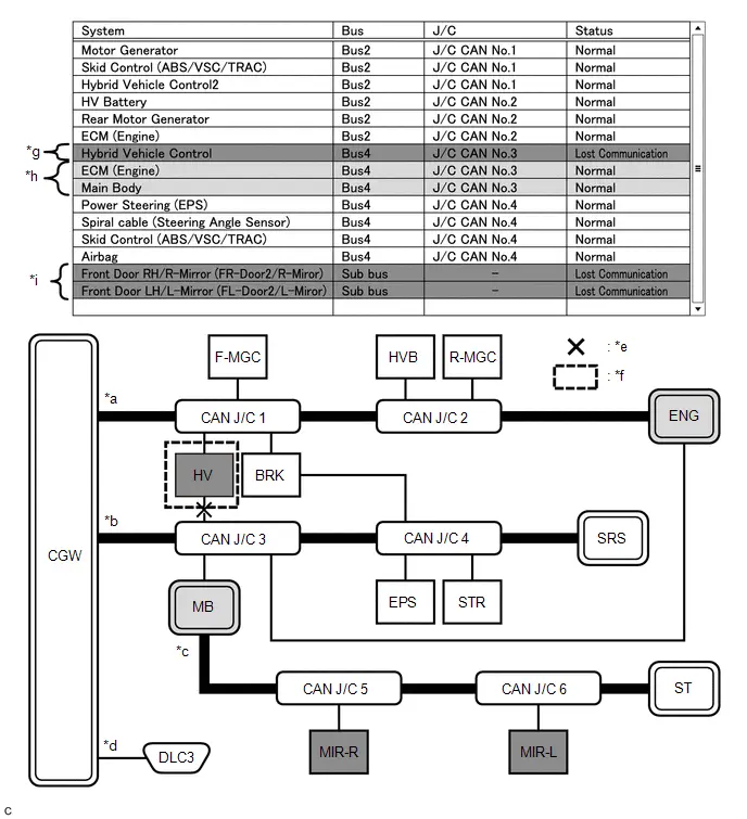
| *a | Bus 2 | *b | Bus 4 |
| *c | Sub bus | *d | Diagnosis bus |
| *e | Location of malfunction 1 (open in a wire of the branch line) | *f | Location of malfunction 2
|
| *g | Background color is red | *h | Background color intermittently becomes yellow or red |
| *i | Not displayed or background color is yellow or red | - | - |
HINT:
- In the "Communication Bus Check" screen shown in the illustration, electrical noise in the CAN bus caused by an open in a wire in the branch line connected to HV interferes with the communication of MB causing unstable communication. Also, since MB is a gateway function equipped ECU, communication of ECUs connected to its respective sub bus will also be unstable.
- In the "Communication Bus Check" screen shown in the illustration, because the background color of HV is red, it is suspected that HV is the most likely cause of the malfunction. Therefore, it is suspected that HV is not communicating.
(h) Problem Symptom Pattern G
| Display on Communication Bus Check Screen | A gateway function equipped ECU is displayed as not communicating in the central bus and ECUs and sensors connected to its respective sub bus are not displayed. |
| Details of Malfunction |
|
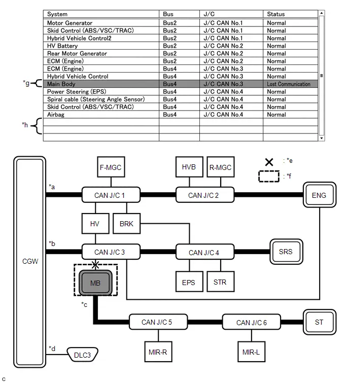
| *a | Bus 2 | *b | Bus 4 |
| *c | Sub bus | *d | Diagnosis bus |
| *e | Location of malfunction 1 (open in both wires of the branch line) | *f | Location of malfunction 2
|
| *g | Background color is red | *h | Not displayed |
HINT:
- If there is a communication malfunction in a gateway function equipped ECU, ECUs connected to its respective sub bus will also be affected and will not be displayed.
- In the "Communication Bus Check" screen shown in the illustration, MB is a gateway function equipped ECU. Therefore, MB is suspected as not communicating.
(i) Problem Symptoms Pattern H
| Display on Communication Bus Check Screen | One ECU or sensor is displayed as not communicating in a sub bus on the "Communication Bus Check" screen. |
| Details of Malfunction |
|

| *a | Bus 2 | *b | Bus 4 |
| *c | Sub bus | *d | Diagnosis bus |
| *e | Location of malfunction 1 (open in both wires of the branch line) | *f | Location of malfunction 2
|
| *g | Background color is red | - | - |
HINT:
- The malfunction in the sub bus will not affect the other buses.
- When a gateway function equipped ECU memorizes ECUs and sensors connected to its respective sub bus and there is a communication malfunction in one of the ECUs or sensors, the background color of the ECU or sensor will change to red and the ECU or sensor will remain displayed.
- The information displayed on the "Communication Bus Check" screen will be the same for an open in both wires of a branch line, an internal malfunction of an ECU or sensor or a malfunction in the power supplied to an ECU or sensor.
(j) Problem Symptom Pattern I
| Display on Communication Bus Check Screen | ECUs or sensors farther from the sub bus monitoring ECU (gateway function equipped ECU) than the open in the wires are displayed as not communicating on the "Communication Bus Check" screen. |
| Details of Malfunction | Open in both wires of the main bus line in the sub bus |
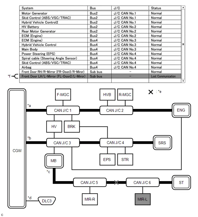
| *a | Bus 2 | *b | Bus 4 |
| *c | Sub bus | *d | Diagnosis bus |
| *e | Location of malfunction (open in both wires of the main bus line) | *f | Background color is red |
HINT:
Due to the malfunction, ECUs or sensors farther from the sub bus monitoring ECU (gateway function equipped ECU) than the open in the wires will be displayed as not communicating and their background color will be red.
How to Use "Communication Bus Check (Detail)" Screen in Inspection
(a) Even if the malfunction cannot be determined on the "Communication Bus Check" screen, determine the malfunctioning part using Communication Bus Check (Detail) as follows:
NOTICE:
- The following CAN bus wiring diagram or communication bus check screen is provided only as an example. This wiring diagram or screen differs from the actual one for this Toyota Prius vehicle.
- The Lost Communication Time column displays the longest period of time in seconds that the central gateway ECU (network gateway ECU) detected a communication stop in the respective ECU or sensor.
- The Lost Communication Trip column displays the trip in which the central gateway ECU (network gateway ECU) detected the longest communication stop in the respective ECU or sensor.
- When using the combo box, it may be possible to select a sub bus from the drop down list that does not have any connected ECUs or sensors. This is not a malfunction and occurs when there is no optional device connected to a sub bus which is monitored by a sub bus monitoring ECU (gateway function equipped ECU).
-
In the drop down list, all sub buses applicable to the model are displayed (e.g. LIN communication sub buses are also displayed). For information on sub buses necessary to diagnose CAN communication system, refer to the System Diagram.
Click here

HINT:
- If the CAN communication system is currently malfunctioning, it is recommended to use Communication Bus Check rather than Communication Bus Check (Detail) for determining the suspected area.
- The communication error history of ECUs or sensors which have communication error history can be displayed on the "Communication Bus Check (Detail)" screen.
- Lost Communication Time and Lost Communication Trip are only displayed for the central bus.
- Lost Communication Time and Lost Communication Trip are not displayed for sub buses.
(b) If there is an ECU or sensor displayed with a red background on the "Communication Bus Check (Detail)" screen to indicate that it was not communicating, it is suspected that the ECU or sensor was not communicating.
| Details of Malfunction | Past malfunction in the wire harness or power supplied to F-MGC in Bus 2 |
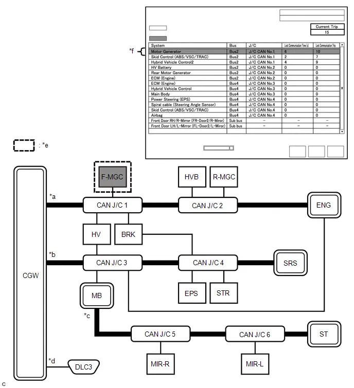
| *a | Bus 2 | *b | Bus 4 |
| *c | Sub bus | *d | Diagnosis bus |
| *e | Location of malfunction
| *f | Background color is red |
| Bus Type | Background Color | Connection Status |
|---|---|---|
| Bus | White | Either of the following:
|
| Red | Lost Communication Time is 6 seconds or more. | |
| Not displayed | Either of the following:
| |
| Sub bus | White | Lost Communication Time is displayed as "-". |
| Not displayed | Either of the following:
|
HINT:
- Check the values of Lost Communication Trip and Current Trip for the ECUs or sensors that have a red background color.
- If the values of Lost Communication Trip and Current Trip are the same for an ECU or sensor, the ECU or sensor is currently not communicating. In this case, it is recommended to use Communication Bus Check rather than Communication Bus Check (Detail) for determining the suspected area.
- In the "Communication Bus Check (Detail)" screen shown in the illustration, F-MGC had a communication malfunction in the 10th trip. Thus, it is suspected that F-MGC was not communicating.
- *1: When the central gateway ECU (network gateway ECU) has an internal malfunction or cannot communicate with the GTS, the name of buses, sub buses, ECUs and sensors will not be displayed.
- *2: When no ECUs or sensors are connected to a bus, the message "There is no system found on the communication Bus." will be displayed.
- *3: When a gateway function equipped ECU cannot communicate with the central gateway ECU (network gateway ECU), the name of sub buses and ECUs or sensors connected to the sub bus will not be displayed.
- *4: When no ECUs or sensors are connected to the sub bus, the message "There is no system found on the communication Bus." will be displayed.
DTC TABLE BY ECU
HINT:
- In the CAN communication system, the CAN communication DTCs of each ECU can be displayed using the GTS.
-
If CAN communication system DTCs are output, the malfunction cannot be determined only by the DTCs. Perform troubleshooting according to How to Proceed with Troubleshooting.
Click here

- DTCs will only be stored if the Check Procedure is performed when the system is currently malfunctioning.
(a) Airbag ECU Assembly / GTS Display "SRS Airbag"
Body Electrical > SRS Airbag > Trouble CodesHINT:
This ECU uses the CAN communication system for DTC communication.
| DTC | Detection Item | DTC Detection Condition |
|---|---|---|
| U012987 | Lost Communication with Brake System Control Module "A" Missing Message | Communication stops between the airbag ECU assembly and the No. 2 skid control ECU (brake actuator assembly). |
| U023A87 | Lost Communication with Image Processing Module "A" Missing Message | Communication stops between the airbag ECU assembly and the forward recognition camera. |
(b) Air Conditioning Amplifier Assembly / GTS Display "Air Conditioner"
Body Electrical > Air Conditioner > Trouble CodesHINT:
This ECU uses the CAN communication system for DTC communication.
| DTC | Detection Item | DTC Detection Condition |
|---|---|---|
| U010087 | Lost Communication with ECM/PCM "A" Missing Message | Communication stops between the air conditioning amplifier assembly and the ECM. |
| U013187 | Lost Communication with Power Steering Control Module Missing Message | Communication stops between the air conditioning amplifier assembly and the power steering ECU assembly. |
| U014087 | Lost Communication with Body Control Module Missing Message | Communication stops between the air conditioning amplifier assembly and the main body ECU (multiplex network body ECU). |
| U015587 | Lost Communication with Instrument Panel Cluster (IPC) Control Module Missing Message | Communication stops between the air conditioning amplifier assembly and the combination meter assembly. |
| U016387 | Lost Communication with Navigation Control Module Missing Message | Communication stops between the air conditioning amplifier assembly and the radio and display receiver assembly. |
| U019887 | Lost Communication with Telematic Control Module "A" Missing Message | Communication stops between the air conditioning amplifier assembly and the DCM (telematics transceiver). |
| U029387 | Lost Communication with Hybrid/EV Powertrain Control Module Missing Message | Communication stops between the air conditioning amplifier assembly and the hybrid Toyota Prius vehicle control ECU. |
(c) No. 1 Skid Control ECU (Brake Booster with Master Cylinder Assembly) / GTS Display "Brake Booster"
Chassis > Brake Booster > Trouble CodesHINT:
This ECU uses the CAN communication system for DTC communication.
| DTC | Detection Item | DTC Detection Condition |
|---|---|---|
| U011000 | Lost Communication with Drive Motor Control Module "A" | Communication stops between the No. 1 skid control ECU (brake booster with master cylinder assembly) and the inverter with converter assembly. |
| U012987 | Lost Communication with Brake System Control Module "A" Missing Message | Communication stops between the No. 1 skid control ECU (brake booster with master cylinder assembly) and the No. 2 skid control ECU (brake actuator assembly). |
| U029300 | Lost Communication with Hybrid/EV Powertrain Control Module | Communication stops between the No. 1 skid control ECU (brake booster with master cylinder assembly) and the hybrid Toyota Prius vehicle control ECU. |
| U110600 | Lost Communication with Electric Parking Brake Module | Communication stops between the No. 1 skid control ECU (brake booster with master cylinder assembly) and the No. 2 skid control ECU (brake actuator assembly). |
| U114A00 | Lost Communication with Sub Battery System (System 2) Missing Message | Communication stops between the No. 1 skid control ECU (brake booster with master cylinder assembly) and the integration control supply. |
| U115000 | Lost Communication with Hybrid Powertrain Control Module (ch2) | Communication stops between the No. 1 skid control ECU (brake booster with master cylinder assembly) and the hybrid Toyota Prius vehicle control ECU. |
| U117D87 | Lost Communication with Brake System Control Module (ch4) Missing Message | Communication stops between the No. 1 skid control ECU (brake booster with master cylinder assembly) and the No. 2 skid control ECU (brake actuator assembly). |
(d) No. 2 Skid Control ECU (Brake Actuator Assembly) / GTS Display "Brake/EPB"
Chassis > Brake/EPB > Trouble CodesHINT:
This ECU uses the CAN communication system for DTC communication.
| DTC | Detection Item | DTC Detection Condition |
|---|---|---|
| U010087 | Lost Communication with ECM/PCM "A" Missing Message | Communication stops between the No. 2 skid control ECU (brake actuator assembly) and the ECM. |
| U010187 | Lost Communication with TCM Missing Message | Communication stops between the No. 2 skid control ECU (brake actuator assembly) and the hybrid Toyota Prius vehicle control ECU. |
| U010387 | Lost Communication with Gear Shift Control Module "A" Missing Message | Communication stops between the No. 2 skid control ECU (brake actuator assembly) and the transmission floor shift assembly. |
| U011087 | Lost Communication with Drive Motor Control Module "A" Missing Message | Communication stops between the No. 2 skid control ECU (brake actuator assembly) and the inverter with converter assembly. |
| U012587 | Lost Communication with Multi-axis Acceleration Sensor Module Missing Message | Communication stops between the No. 2 skid control ECU (brake actuator assembly) and the airbag ECU assembly. |
| U012687 | Lost Communication with Steering Angle Sensor Module Missing Message | Communication stops between the No. 2 skid control ECU (brake actuator assembly) and the steering sensor. |
| U013187 | Lost Communication with Power Steering Control Module Missing Message | Communication stops between the No. 2 skid control ECU (brake actuator assembly) and the power steering ECU assembly. |
| U014087 | Lost Communication with Body Control Module Missing Message | Communication stops between the No. 2 skid control ECU (brake actuator assembly) and the main body ECU (multiplex network body ECU). |
| U015187 | Lost Communication with Restraints Control Module Missing Message | Communication stops between the No. 2 skid control ECU (brake actuator assembly) and the airbag ECU assembly. |
| U025E87 | Lost Communication with Electronic Brake Booster Control Module "A" Missing Message | Communication stops between the No. 2 skid control ECU (brake actuator assembly) and the No. 1 skid control ECU (brake booster with master cylinder assembly). |
| U029387 | Lost Communication with Hybrid/EV Powertrain Control Module Missing Message | Communication stops between the No. 2 skid control ECU (brake actuator assembly) and the hybrid Toyota Prius vehicle control ECU. |
| U110787 | Lost Communication with Power Management Module Missing Message | Communication stops between the No. 2 skid control ECU (brake actuator assembly) and the certification ECU (smart key ECU assembly). |
| U111A87 | Lost Communication with ECM/PCM "A" (ch2) Missing Message | Communication stops between the No. 2 skid control ECU (brake actuator assembly) and the ECM. |
| U115087 | Lost Communication with Hybrid Powertrain Control Module (ch2) Missing Message | Communication stops between the No. 2 skid control ECU (brake actuator assembly) and the hybrid Toyota Prius vehicle control ECU. |
| U115987 | Lost Communication With Electronic Brake Booster Control Module "A" (ch3) Missing Message | Communication stops between the No. 2 skid control ECU (brake actuator assembly) and the No. 1 skid control ECU (brake booster with master cylinder assembly). |
(e) Tire Pressure Warning ECU and Receiver / GTS Display "Tire Pressure Monitor"
Chassis > Tire Pressure Monitor > Trouble CodesHINT:
This ECU uses the CAN communication system for DTC communication.
| DTC | Detection Item | DTC Detection Condition |
|---|---|---|
| U012987 | Lost Communication with Brake System Control Module "A" Missing Message | Communication stops between the tire pressure warning ECU and receiver and the No. 2 skid control ECU (brake actuator assembly). |
(f) Power Steering ECU Assembly / GTS Display "EMPS"
Chassis > EMPS > Trouble CodesHINT:
This ECU uses the CAN communication system for DTC communication.
| DTC | Detection Item | DTC Detection Condition |
|---|---|---|
| U012687 | Lost Communication with Steering Angle Sensor Module Missing Message | Communication stops between the power steering ECU assembly and the steering sensor. |
| U012987 | Lost Communication with Brake System Control Module Missing Message | Communication stops between the power steering ECU assembly and the No. 2 skid control ECU (brake actuator assembly). |
| U023A87 | Lost Communication with Image Processing Module "A" Missing Message | Communication stops between the power steering ECU assembly and the forward recognition camera. |
| U029387 | Lost Communication with Hybrid/EV Powertrain Control Module Missing Message | Communication stops between the power steering ECU assembly and the hybrid Toyota Prius vehicle control ECU. |
| U111087 | Lost Communication with Clearance Sonar Module | Communication stops between the power steering ECU assembly and the clearance warning ECU assembly. |
(g) Combination Meter Assembly / GTS Display "Combination Meter"
Body Electrical > Combination Meter > Trouble CodesHINT:
This ECU uses the CAN communication system for DTC communication.
| DTC | Detection Item | DTC Detection Condition |
|---|---|---|
| U010087 | Lost Communication with ECM/PCM "A" Missing Message | Communication stops between the combination meter assembly and the ECM. |
| U010387 | Lost Communication with Gear Shift Control Module "A" Missing Message | Communication stops between the combination meter assembly and the transmission floor shift assembly. |
| U012687 | Lost Communication with Steering Angle Sensor Module Missing Message | Communication stops between the combination meter assembly and the steering sensor. |
| U012787 | Lost Communication with Tire Pressure Monitor Module Missing Message | Communication stops between the combination meter assembly and the tire pressure warning ECU and receiver. |
| U012987 | Lost Communication with Brake System Control Module Missing Message | Communication stops between the combination meter assembly and the No. 2 skid control ECU (brake actuator assembly). |
| U013187 | Lost Communication with Power Steering Control Module Missing Message | Communication stops between the combination meter assembly and the power steering ECU assembly. |
| U014087 | Lost Communication with Body Control Module Missing Message | Communication stops between the combination meter assembly and the main body ECU (multiplex network body ECU). |
| U015187 | Lost Communication with Restraints Control Module Missing Message | Communication stops between the combination meter assembly and the airbag ECU assembly. |
| U016387 | Lost Communication with Navigation Control Module Missing Message | Communication stops between the combination meter assembly and the radio and display receiver assembly. |
| U016487 | Lost Communication with HVAC Control Module Missing Message | Communication stops between the combination meter assembly and the air conditioning amplifier assembly. |
| U016887 | Lost Communication with Toyota Prius Vehicle Security Control Module Missing Message | Communication stops between the combination meter assembly and the certification ECU (smart key ECU assembly). |
| U023387 | Lost Communication with Side Obstacle Detection Control Module "B" Missing Message | Communication stops between the combination meter assembly and the blind spot monitor sensor LH (B). |
| U023A87 | Lost Communication with Image Processing Module "A" Missing Message | Communication stops between the combination meter assembly and the forward recognition camera. |
| U023B87 | Lost Communication with Image Processing Module "B" Missing Message | Communication stops between the combination meter assembly and the parking assist ECU. |
| U029387 | Lost Communication with Hybrid/EV Powertrain Control Module Missing Message | Communication stops between the combination meter assembly and the hybrid Toyota Prius vehicle control ECU. |
| U110687 | Lost Communication with Electric Parking Brake Module Missing Message | Communication stops between the combination meter assembly and the No. 2 skid control ECU (brake actuator assembly). |
| U111087 | Lost Communication with Clearance Sonar Module Missing Message | Communication stops between the combination meter assembly and the clearance warning ECU assembly. |
| U111287 | Lost Communication with Combination Switch Module Missing Message | Communication stops between the combination meter assembly and the steering sensor. |
| U113387 | Lost Communication with PMN Module Missing Message | Communication stops between the combination meter assembly and the certification ECU (smart key ECU assembly). |
(h) DCM (Telematics Transceiver) / GTS Display "Telematics"
Body Electrical > Telematics > Trouble CodesHINT:
This ECU uses the CAN communication system for DTC communication.
| DTC | Detection Item | DTC Detection Condition |
|---|---|---|
| U014087 | Lost Communication with Body Control Module Missing Message | Communication stops between the DCM (telematics transceiver) and the main body ECU (multiplex network body ECU). |
| U015587 | Lost Communication with Instrument Panel Cluster (IPC) Control Module Missing Message | Communication stops between the DCM (telematics transceiver) and the combination meter assembly. |
| U016387 | Lost Communication with Navigation Control Module Missing Message | Communication stops between the DCM (telematics transceiver) and the radio and display receiver assembly. |
(i) Toyota Prius Vehicle Approaching Speaker Controller / GTS Display "Acoustic Vehicle Alerting System"
Body Electrical > Acoustic Vehicle Alerting System > Trouble CodesHINT:
This ECU uses the CAN communication system for DTC communication.
| DTC | Detection Item | DTC Detection Condition |
|---|---|---|
| U012987 | Lost Communication with Brake System Control Module Missing Message | Communication stops between the Toyota Prius vehicle approaching speaker controller and the No. 2 skid control ECU (brake actuator assembly). |
| U014087 | Lost Communication with Body Control Module Missing Message | Communication stops between the Toyota Prius vehicle approaching speaker controller and the main body ECU (multiplex network body ECU). |
| U029387 | Lost Communication with Hybrid/EV Powertrain Control Module Missing Message | Communication stops between the Toyota Prius vehicle approaching speaker controller and the hybrid vehicle control ECU. |
| U032257 | Software Incompatibility with Body Control Module Invalid / Incompatible Software Component | The Toyota Prius vehicle information from the main body ECU (multiplex network body ECU) and that stored in the vehicle approaching speaker controller do not match. |
(j) Position Control ECU Assembly LH / GTS Display "Driver Seat"
Body Electrical > Driver Seat > Trouble CodesHINT:
This ECU uses the CAN communication system for DTC communication.
| DTC | Detection Item | DTC Detection Condition |
|---|---|---|
| U010087 | Lost Communication with ECM/PCM "A" Missing Message | Communication stops between the position control ECU assembly LH and the ECM. |
| U012987 | Lost Communication with Brake System Control Module "A" Missing Message | Communication stops between the position control ECU assembly LH and the No. 2 skid control ECU (brake actuator assembly). |
| U014087 | Lost Communication with Body Control Module Missing Message | Communication stops between the position control ECU assembly LH and the main body ECU (multiplex network body ECU). |
| U016387 | Lost Communication with Navigation Control Module Missing Message | Communication stops between the position control ECU assembly LH and the radio and display receiver assembly. |
| U110787 | Lost Communication with Power Management Module Missing Message | Communication stops between the position control ECU assembly LH and the certification ECU (smart key ECU assembly). |
| U114F87 | Lost Communication with Power Integration Module Missing Message | Communication stops between the position control ECU assembly LH and the main body ECU (multiplex network body ECU). |
(k) Parking Assist ECU / GTS Display "Circumference Monitoring Camera Control Module"
Chassis > Circumference Monitoring Camera Control Module > Trouble CodesHINT:
- This ECU uses the CAN communication system for DTC communication.
-
*: Refer to Panoramic View Monitor System.
Click here

| DTC | Detection Item | DTC Detection Condition |
|---|---|---|
| U012687 | Lost Communication with Steering Angle Sensor Module Missing Message | Communication stops between the parking assist ECU and the steering sensor. |
| U012987 | Lost Communication with Brake System Control Module "A" Missing Message | Communication stops between the parking assist ECU and the No. 2 skid control ECU (brake actuator assembly). |
| U013187 | Lost Communication with Power Steering Control Module Missing Message | Communication stops between the parking assist ECU and the power steering ECU assembly. |
| U014087 | Lost Communication with Body Control Module Missing Message | Communication stops between the parking assist ECU and the main body ECU (multiplex network body ECU). |
| U015587 | Lost Communication with Instrument Panel Cluster (IPC) Control Module Missing Message | Communication stops between the parking assist ECU and the combination meter assembly. |
| U016387 | Lost Communication with Navigation Control Module Missing Message | Communication stops between the parking assist ECU and the radio and display receiver assembly. |
| U019887 | Lost Communication with Telematic Control Module "A" Missing Message | Communication stops between the parking assist ECU and the DCM (telematics transceiver). |
| U029387 | Lost Communication with Hybrid/EV Powertrain Control Module Missing Message | Communication stops between the parking assist ECU and the hybrid Toyota Prius vehicle control ECU. |
| U111087 | Lost Communication with Clearance Sonar Module Missing Message | Communication stops between the parking assist ECU and the clearance warning ECU assembly. |
| U11B687* | Lost Communication with Clearance Sonar Module (ch2) Missing Message | Communication stops between the parking assist ECU and the clearance warning ECU assembly. |
(l) Blind Spot Monitor Sensor LH (B) / GTS Display "Blind Spot Monitor "B""
Body Electrical > Blind Spot Monitor "B" > Trouble CodesHINT:
- This ECU uses the CAN communication system for DTC communication.
-
*: Refer to Blind Spot Monitor System.
Click here


| DTC | Detection Item | DTC Detection Condition |
|---|---|---|
| U012987 | Lost Communication with Brake System Control Module "A" Missing Message | Communication stops between the blind spot monitor sensor LH (B) and the No. 2 skid control ECU (brake actuator assembly). |
| U013187 | Lost Communication with Power Steering Control Module "A" Missing Message | Communication stops between the blind spot monitor sensor LH (B) and the power steering ECU assembly. |
| U014087 | Lost Communication with Body Control Module Missing Message | Communication stops between the blind spot monitor sensor LH (B) and the main body ECU (multiplex network body ECU). |
| U016387 | Lost Communication with Navigation Control Module Missing Message | Communication stops between the blind spot monitor sensor LH (B) and the radio and display receiver assembly. |
| U023287* | Lost Communication with Side Obstacle Detection Control Module "A" Missing Message | Communication stops between the blind spot monitor sensor LH (B) and the blind spot monitor sensor RH (A). |
| U029387 | Lost Communication with Hybrid/EV Powertrain Control Module Missing Message | Communication stops between the blind spot monitor sensor LH (B) and the hybrid Toyota Prius vehicle control ECU. |
| U032251* | Software Incompatibility with Body Control Module Not Programmed | Destination information of the main body ECU (multiplex network body ECU) and the blind spot monitor sensor LH (B) do not match. |
| U032257* | Software Incompatibility with Body Control Module Invalid / Incompatible Software Component | Destination information of the main body ECU (multiplex network body ECU) and the blind spot monitor sensor LH (B) do not match. |
| U114F87 | Lost Communication with Power Integration Module Missing Message | Communication stops between the blind spot monitor sensor LH (B) and the main body ECU (multiplex network body ECU). |
(m) Blind Spot Monitor Sensor RH (A) / GTS Display "Blind Spot Monitor "A""
Body Electrical > Blind Spot Monitor "A" > Trouble CodesHINT:
- This ECU uses the CAN communication system for DTC communication.
-
*: Refer to Blind Spot Monitor System.
Click here


| DTC | Detection Item | DTC Detection Condition |
|---|---|---|
| U023387* | Lost Communication with Side Obstacle Detection Control Module "B" Missing Message | Communication stops between the blind spot monitor sensor RH (A) and the blind spot monitor sensor LH (B). |
| U032251* | Software Incompatibility with Body Control Module Not Programmed | Destination information of the main body ECU (multiplex network body ECU) and the blind spot monitor sensor RH (A) do not match. |
| U032257* | Software Incompatibility with Body Control Module Invalid / Incompatible Software Component | Destination information of the main body ECU (multiplex network body ECU) and the blind spot monitor sensor RH (A) do not match. |
(n) Transmission Floor Shift Assembly / GTS Display "Hybrid Control"
Powertrain > Hybrid Control > Trouble CodesHINT:
- This ECU uses the CAN communication system for DTC communication.
-
*: Refer to Electronic Shift Lever System.
Click here


| DTC | Detection Item | DTC Detection Condition |
|---|---|---|
| P175387* | Lost Communication with Gear Shift Control Module "B" (Local-CAN) Missing Message | When the ignition switch is ON and the auxiliary battery voltage is a certain value or more, a communication malfunction is continuously detected in the CAN (SBW BUS) by the shift actuator ECU. |
| P178987* | Lost Communication with Gear Shift Control Module "A" from "B" Missing Message | When the ignition switch is ON (IG) and the auxiliary battery voltage is a certain value or more, a CAN communication malfunction with the shift control ECU is detected |
| U014000 | Lost Communication with Body Control Module (Sub) Missing Message | Communication stops between the transmission floor shift assembly and the main body ECU (multiplex network body ECU). |
| U015586 | Lost Communication with Instrument Panel Cluster (IPC) Control Module Signal (some circuit quantity, reported via serial data) Invalid | Communication stops between the transmission floor shift assembly and the combination meter assembly. |
| U029100* | Lost Communication with Gear Shift Control Module "B" (System 2) Missing Message | Communication stops between the transmission floor shift assembly and the shift control actuator assembly. |
| U029300 | Lost Communication with Hybrid/EV Powertrain Control Module from Gear Shift Control Module "A" | Communication stops between the transmission floor shift assembly and the hybrid Toyota Prius vehicle control ECU. |
| U110700 | Lost Communication with Power Management Module (Gear Shift Control Module "A") | Communication stops between the transmission floor shift assembly and the certification ECU (smart key ECU assembly). |
| U114F00 | Lost Communication with Power Integration Module (System 2) Missing Message | Communication stops between the transmission floor shift assembly and the main body ECU (multiplex network body ECU). |
| U117000 | Lost Communication with Brake System Control Module (Gear Shift Control Module "A") | Communication stops between the transmission floor shift assembly and the No. 1 skid control ECU (brake booster with master cylinder assembly). |
(o) Hybrid Toyota Prius Vehicle Control ECU / GTS Display "Hybrid Control"
Powertrain > Hybrid Control > Trouble CodesHINT:
- This ECU uses the CAN communication system for DTC communication.
-
*: Refer to Hybrid Control System.
for M20A-FXS:
Click here

for 2ZR-FXE:
Click here

| DTC | Detection Item | DTC Detection Condition |
|---|---|---|
| U010087 | Lost Communication with ECM/PCM "A" Missing Message | Communication stops between the hybrid Toyota Prius vehicle control ECU and the ECM. |
| U010387 | Lost Communication with Gear Shift Control Module "A" (Hybrid/EV Battery Local Bus) Missing Message | Communication stops between the hybrid Toyota Prius vehicle control ECU and the transmission floor shift assembly. |
| U011087 | Lost Communication with Drive Motor Control Module "A" Missing Message | Communication stops between the hybrid Toyota Prius vehicle control ECU and the inverter with converter assembly. |
| U011187 | Lost Communication with Hybrid/EV Battery Energy Control Module "A" Missing Message | Communication stops between the hybrid Toyota Prius vehicle control ECU and the battery ECU assembly. |
| U012687 | Lost Communication with Steering Angle Sensor Module Missing Message | Communication stops between the hybrid Toyota Prius vehicle control ECU and the steering sensor. |
| U012987 | Lost Communication with Brake System Control Module Missing Message | Communication stops between the hybrid Toyota Prius vehicle control ECU and the No. 2 skid control ECU (brake actuator assembly). |
| U013187 | Lost Communication with Power Steering Control Module "A" Missing Message | Communication stops between the hybrid Toyota Prius vehicle control ECU and the power steering ECU assembly. |
| U014087 | Lost Communication with Body Control Module Missing Message | Communication stops between the hybrid Toyota Prius vehicle control ECU and the main body ECU (multiplex network body ECU). |
| U015187 | Lost Communication with Restraints Control Module Missing Message | Communication stops between the hybrid Toyota Prius vehicle control ECU and the airbag ECU assembly. |
| U015500 | Lost Communication With Instrument Panel Cluster (IPC) Control Module | Communication stops between the hybrid Toyota Prius vehicle control ECU and the combination meter assembly. |
| U016487 | Lost Communication with HVAC Control Module Missing Message | Communication stops between the hybrid Toyota Prius vehicle control ECU and the air conditioning amplifier assembly. |
| U01BD87 | Lost Communication with DC/DC Converter Control Module "C" Missing Message | Communication stops between the hybrid Toyota Prius vehicle control ECU and the inverter with converter assembly. |
| U029187* | Lost Communication with Gear Shift Control Module "B" Missing Message | Communication stops between the hybrid Toyota Prius vehicle control ECU and the transmission floor shift assembly. |
| U042481* | HVAC Control Module to Hybrid/EV Powertrain Control Module Invalid Serial Data Received | The hybrid Toyota Prius vehicle control ECU receives an abnormal operation value command from the air conditioning amplifier assembly. |
| U110787 | Lost Communication with Power Management Module Missing Message | Communication stops between the hybrid Toyota Prius vehicle control ECU and the certification ECU (smart key ECU assembly). |
| U111A87 | Lost Communication with ECM/PCM "A" (ch2) Missing Message | Communication stops between the hybrid Toyota Prius vehicle control ECU and the ECM. |
| U115487 | Lost Communication with Drive Motor Control Module "A" (ch2) Missing Message | Communication stops between the hybrid Toyota Prius vehicle control ECU and the inverter with converter assembly. |
| U117087 | Lost Communication with Brake System Control Module (Secondary CAN Line) Missing Message | Communication stops between the hybrid Toyota Prius vehicle control ECU and the No. 2 skid control ECU (brake actuator assembly). |
| U117687* | Lost Communication with Gear Shift Control Module "A" (Powertrain Bus) Missing Message | Communication stops between the hybrid Toyota Prius vehicle control ECU and the transmission floor shift assembly. |
| U117B87 | Lost Communication with Hybrid/EV Battery Energy Control Module "A" (ch2) Missing Message | Communication stops between the hybrid Toyota Prius vehicle control ECU and the battery ECU assembly. |
| U117E87* | Lost Communication with Drive Motor Control Module "A" (ch4) Missing Message | Communication stops between the hybrid Toyota Prius vehicle control ECU and the inverter with converter assembly. |
| U11BC87 | Lost Communication with Hybrid/EV Powertrain Control Module (ch6) Missing Message | Communication stops between the hybrid Toyota Prius vehicle control ECU and the No. 2 skid control ECU (brake actuator assembly). |
(p) Inverter with Converter Assembly / GTS Display "Motor Generator"
Powertrain > Motor Generator > Trouble CodesHINT:
- This ECU uses the CAN communication system for DTC communication.
-
*: Refer to Motor Generator Control System.
for M20A-FXS:
Click here

for 2ZR-FXE:
Click here

| DTC | Detection Item | DTC Detection Condition |
|---|---|---|
| U010087 | Lost Communication with ECM/PCM "A" Missing Message | Communication stops between the inverter with converter assembly and the ECM. |
| U029387 | Lost Communication with Hybrid/EV Powertrain Control Module Missing Message | Communication stops between the inverter with converter assembly and the hybrid Toyota Prius vehicle control ECU. |
| U117008 | Lost Communication with Brake System Control Module (ch2) Bus Signal / Message Failure | Communication stops between the inverter with converter assembly and the No. 2 skid control ECU (brake actuator assembly). |
| U117087 | Lost Communication with Brake System Control Module(ch2) Missing Message | Communication stops between the inverter with converter assembly and the No. 2 skid control ECU (brake actuator assembly). |
| U11B300* | Lost Communication with Hybrid/EV Powertrain Control Module (ch5) (System 2) Missing Message | Communication stops between the inverter with converter assembly and the hybrid Toyota Prius vehicle control ECU. |
| U11B387* | Lost Communication with Hybrid/EV Powertrain Control Module (ch5) Missing Message | Communication stops between the inverter with converter assembly and the hybrid Toyota Prius vehicle control ECU. |
(q) Main Body ECU (Multiplex Network Body ECU) / GTS Display "Main Body"
Body Electrical > Main Body > Trouble CodesHINT:
This ECU uses the CAN communication system for DTC communication.
| DTC | Detection Item | DTC Detection Condition |
|---|---|---|
| U010087 | Lost Communication with ECM/PCM "A" Missing Message | Communication stops between the main body ECU (multiplex network body ECU) and the ECM. |
| U010187 | Lost Communication with TCM Missing Message | Communication stops between the main body ECU (multiplex network body ECU) and the hybrid Toyota Prius vehicle control ECU. |
| U011187 | Lost Communication with Battery Energy Control Module "A" Missing Message | Communication stops between the main body ECU (multiplex network body ECU) and the battery ECU assembly. |
| U012687 | Lost Communication with Steering Angle Sensor Module Missing Message | Communication stops between the main body ECU (multiplex network body ECU) and the steering sensor. |
| U012987 | Lost Communication with Brake System Control Module "A" Missing Message | Communication stops between the main body ECU (multiplex network body ECU) and the No. 2 skid control ECU (brake actuator assembly). |
| U015187 | Lost Communication with Restraints Control Module Missing Message | Communication stops between the main body ECU (multiplex network body ECU) and the airbag ECU assembly. |
| U015587 | Lost Communication with Instrument Panel Cluster (IPC) Control Module Missing Message | Communication stops between the main body ECU (multiplex network body ECU) and the combination meter assembly. |
| U016387 | Lost Communication with Navigation Control Module Missing Message | Communication stops between the main body ECU (multiplex network body ECU) and the radio and display receiver assembly. |
| U016487 | Lost Communication with HVAC Control Module Missing Message | Communication stops between the main body ECU (multiplex network body ECU) and the air conditioning amplifier assembly. |
| U016887 | Lost Communication with Toyota Prius Vehicle Security Control Module Missing Message | Communication stops between the main body ECU (multiplex network body ECU) and the certification ECU (smart key ECU assembly). |
| U020887 | Lost Communication with "Seat Control Module A" Missing Message | Communication stops between the main body ECU (multiplex network body ECU) and the position control ECU assembly LH. |
| U023087 | Lost Communication with Rear Gate Module Missing Message | Communication stops between the main body ECU (multiplex network body ECU) and the multiplex network door ECU. |
| U023387 | Lost Communication with Side Obstacle Detection Control Module "B" Missing Message | Communication stops between the main body ECU (multiplex network body ECU) and the blind spot monitor sensor LH (B). |
| U023A87 | Lost Communication with Image Processing Module "A" Missing Message | Communication stops between the main body ECU (multiplex network body ECU) and the forward recognition camera. |
| U029387 | Lost Communication with Hybrid/EV Powertrain Control Module Missing Message | Communication stops between the main body ECU (multiplex network body ECU) and the hybrid Toyota Prius vehicle control ECU. |
| U110487 | Lost Communication with Driving Support ECU Missing Message | Communication stops between the main body ECU (multiplex network body ECU) and the forward recognition camera. |
| U110687 | Lost Communication with Electric Parking Brake Module Missing Message | Communication stops between the main body ECU (multiplex network body ECU) and the No. 2 skid control ECU (brake actuator assembly). |
| U110787 | Lost Communication with Power Management Module Missing Message | Communication stops between the main body ECU (multiplex network body ECU) and the certification ECU (smart key ECU assembly). |
| U111087 | Lost Communication with Clearance Sonar Module Missing Message | Communication stops between the main body ECU (multiplex network body ECU) and the clearance warning ECU assembly. |
| U111787 | Lost Communication with Accessory Gateway Missing Message | Communication stops between the main body ECU (multiplex network body ECU) and the option connector (bus buffer ECU) or DCM (telematics transceiver). |
(r) Radio and Display Receiver Assembly / GTS Display "Navigation System"
Body Electrical > Navigation System > Trouble CodesHINT:
- This ECU uses the CAN communication system for DTC communication.
-
*: Refer to Audio and Visual System.
Click here


| DTC | Detection Item | DTC Detection Condition |
|---|---|---|
| U010087 | Lost Communication with ECM/PCM "A" Missing Message | Communication stops between the radio and display receiver assembly and the ECM. |
| U012987 | Lost Communication with Brake System Control Module "A" Missing Message | Communication stops between the radio and display receiver assembly and the No. 2 skid control ECU (brake actuator assembly). |
| U014087 | Lost Communication with Body Control Module Missing Message | Communication stops between the radio and display receiver assembly and the main body ECU (multiplex network body ECU). |
| U015587 | Lost Communication with Instrument Panel Cluster (IPC) Control Module Missing Message | Communication stops between the radio and display receiver assembly and the combination meter assembly. |
| U016487 | Lost Communication with HVAC Control Module Missing Message | Communication stops between the radio and display receiver assembly and the air conditioning amplifier assembly. |
| U016887 | Lost Communication with Toyota Prius Vehicle Security Control Module Missing Message | Communication stops between the radio and display receiver assembly and the certification ECU (smart key ECU assembly). |
| U019887 | Lost Communication with Telematic Control Module "A" Missing Message | Communication stops between the radio and display receiver assembly and the DCM (telematics transceiver). |
| U023B87 | Lost Communication with Image Processing Module "B" Missing Message | Communication stops between the radio and display receiver assembly and the parking assist ECU. |
| U026587 | Lost Communication with Image Processing Sensor A Missing Message | Communication stops between the radio and display receiver assembly and the rear television camera assembly. |
| U029387 | Lost Communication with Hybrid/EV Powertrain Control Module Missing Message | Communication stops between the radio and display receiver assembly and the hybrid Toyota Prius vehicle control ECU. |
| U100049 | CAN Register Fixing Internal Electronic Failure |
|
| U111087 | Lost Communication with Clearance Sonar Module Missing Message | Communication stops between the radio and display receiver assembly and the clearance warning ECU assembly. |
| U11D087* | Lost Local Communication with MET Missing Message | Communication stops between the radio and display receiver assembly and the combination meter assembly. |
(s) Clearance Warning ECU Assembly / GTS Display "Clearance Warning"
Body Electrical > Clearance Warning > Trouble CodesHINT:
- This ECU uses the CAN communication system for DTC communication.
-
*1: Refer to Parking Support Brake System.
Click here

-
*2: Refer to Advanced Park.
Click here

| DTC | Detection Item | DTC Detection Condition |
|---|---|---|
| U010087 | Lost Communication with ECM/PCM "A" Missing Message | Communication stops between the clearance warning ECU assembly and the ECM. |
| U010387 | Lost Communication with Gear Shift Control Module "A" Missing Message | Communication stops between the clearance warning ECU assembly and the transmission floor shift assembly. |
| U012687 | Lost Communication with Steering Angle Sensor Module Missing Message | Communication stops between the clearance warning ECU assembly and the steering sensor. |
| U012987 | Lost Communication with Brake System Control Module Missing Message | Communication stops between the clearance warning ECU assembly and the No. 2 skid control ECU (brake actuator assembly). |
| U013187 | Lost Communication with Power Steering Control Module Missing Message | Communication stops between the clearance warning ECU assembly and the power steering ECU assembly. |
| U014087 | Lost Communication with Body Control Module Missing Message | Communication stops between the clearance warning ECU assembly and the main body ECU (multiplex network body ECU). |
| U015587 | Lost Communication with Instrument Panel Cluster (IPC) Control Module Missing Message | Communication stops between the clearance warning ECU assembly and the combination meter assembly. |
| U016387 | Lost Communication with Navigation Control Module Missing Message | Communication stops between the clearance warning ECU assembly and the radio and display receiver assembly. |
| U016487 | Lost Communication with HVAC Control Module Missing Message | Communication stops between the clearance warning ECU assembly and the air conditioning amplifier assembly. |
| U023387 | Lost Communication with Side Obstacle Detection Control Module "B" Missing Message | Communication stops between the clearance warning ECU assembly and the blind spot monitor sensor LH (B). |
| U023A87 | Lost Communication with Image Processing Module "A" Missing Message | Communication stops between the clearance warning ECU assembly and the forward recognition camera. |
| U023B87 | Lost Communication with Image Processing Module "B" Missing Message | Communication stops between the clearance warning ECU assembly and the parking assist ECU. |
| U026587 | Lost Communication with Image Processing Sensor A Missing Message | Communication stops between the clearance warning ECU assembly and the rear television camera assembly. |
| U029387 | Lost Communication with Hybrid/EV Powertrain Control Module Missing Message | Communication stops between the clearance warning ECU assembly and the hybrid Toyota Prius vehicle control ECU. |
| U110687 | Lost Communication with Electric Parking Brake Module Missing Message | Communication stops between the clearance warning ECU assembly and the No. 2 skid control ECU (brake actuator assembly). |
| U117787*1 | Lost Communication with Side Obstacle Detection Control Module "A" (ch2) Missing Message | Communication stops between the clearance warning ECU assembly and the blind spot monitor sensor RH (A). |
| U117987*2 | Lost Communication with Image Processing Module "B" (ch2) Missing Message | Communication stops between the clearance warning ECU assembly and the parking assist ECU. |
(t) ECM / GTS Display "Engine"
Powertrain > Engine > Trouble CodesHINT:
This ECU uses the CAN communication system for DTC communication.
| DTC | Detection Item | DTC Detection Condition |
|---|---|---|
| U011087 | Lost Communication with Drive Motor Control Module "A" Missing Message | Communication stops between the ECM and the inverter with converter assembly. |
| U011187 | Lost Communication with Battery Energy Control Module "A" Missing Message | Communication stops between the ECM and the battery ECU assembly. |
| U012987 | Lost Communication with Brake System Control Module Missing Message | Communication stops between the ECM and the No. 2 skid control ECU (brake actuator assembly). |
| U029387 | Lost Communication with Hybrid Powertrain Control Module Missing Message | Communication stops between the ECM and the hybrid Toyota Prius vehicle control ECU. |
| U115087 | Lost Communication with Hybrid Powertrain Control Module (ch2) Missing Message | Communication stops between the ECM and the hybrid Toyota Prius vehicle control ECU. |
| U115487 | Lost Communication with Drive Motor Control Module "A" (ch2) Missing Message | Communication stops between the ECM and the inverter with converter assembly. |
(u) Certification ECU (Smart Key ECU Assembly) / GTS Display "Smart Key"
Body Electrical > Smart Key > Trouble CodesHINT:
This ECU uses the CAN communication system for DTC communication.
| DTC | Detection Item | DTC Detection Condition |
|---|---|---|
| U010087 | Lost Communication with ECM/PCM "A" Missing Message | Communication stops between the certification ECU (smart key ECU assembly) and the hybrid Toyota Prius vehicle control ECU. |
| U012987 | Lost Communication with Brake System Control Module "A" Missing Message | Communication stops between the certification ECU (smart key ECU assembly) and the No. 2 skid control ECU (brake actuator assembly). |
| U014087 | Lost Communication with Body Control Module Missing Message | Communication stops between the certification ECU (smart key ECU assembly) and the main body ECU (multiplex network body ECU). |
| U015587 | Lost Communication with Instrument Panel Cluster (IPC) Control Module Missing Message | Communication stops between the certification ECU (smart key ECU assembly) and the combination meter assembly. |
| U016387 | Lost Communication with Navigation Control Module Missing Message | Communication stops between the certification ECU (smart key ECU assembly) and the radio and display receiver assembly. |
| U016487 | Lost Communication with HVAC Control Module Missing Message | Communication stops between the certification ECU (smart key ECU assembly) and the air conditioning amplifier assembly. |
| U023087 | Lost Communication with Rear Gate Module Missing Message | Communication stops between the certification ECU (smart key ECU assembly) and the multiplex network door ECU. |
| U029387 | Lost Communication with Hybrid/EV Powertrain Control Module Missing Message | Communication stops between the certification ECU (smart key ECU assembly) and the hybrid Toyota Prius vehicle control ECU. |
| U111087 | Lost Communication with Intuitive Parking Assist Module Missing Message | Communication stops between the certification ECU (smart key ECU assembly) and the clearance warning ECU assembly. |
| U111787 | Lost Communication with Accessory Gateway Missing Message | Communication stops between the certification ECU (smart key ECU assembly) and the option connector (bus buffer ECU). |
(v) Certification ECU (Smart Key ECU Assembly) / GTS Display "Power Source Control"
Body Electrical > Power Source Control > Trouble CodesHINT:
This ECU uses the CAN communication system for DTC communication.
| DTC | Detection Item | DTC Detection Condition |
|---|---|---|
| U010087 | Lost Communication with ECM/PCM "A" Missing Message | Communication stops between the certification ECU (smart key ECU assembly) and the ECM. |
| U010387 | Lost Communication with Gear Shift Control Module "A" Missing Message | Communication stops between the certification ECU (smart key ECU assembly) and the transmission floor shift assembly. |
| U012987 | Lost Communication with Brake System Control Module "A" Missing Message | Communication stops between the certification ECU (smart key ECU assembly) and the No. 2 skid control ECU (brake actuator assembly). |
| U014087 | Lost Communication with Body Control Module Missing Message | Communication stops between the certification ECU (smart key ECU assembly) and the main body ECU (multiplex network body ECU). |
| U015587 | Lost Communication with Instrument Panel Cluster (IPC) Control Module Missing Message | Communication stops between the certification ECU (smart key ECU assembly) and the combination meter assembly. |
| U016387 | Lost Communication with Navigation Control Module Missing Message | Communication stops between the certification ECU (smart key ECU assembly) and the radio and display receiver assembly. |
| U016487 | Lost Communication with HVAC Control Module Missing Message | Communication stops between the certification ECU (smart key ECU assembly) and the air conditioning amplifier assembly. |
| U029387 | Lost Communication with Hybrid/EV Powertrain Control Module Missing Message | Communication stops between the certification ECU (smart key ECU assembly) and the hybrid Toyota Prius vehicle control ECU. |
| U111087 | Lost Communication with Clearance Sonar Module Missing Message | Communication stops between the certification ECU (smart key ECU assembly) and the clearance warning ECU assembly. |
| U111787 | Lost Communication with Accessory Gateway Missing Message | Communication stops between the certification ECU (smart key ECU assembly) and the option connector (bus buffer ECU). |
(w) Multiplex Network Door ECU / GTS Display "Back Door"
Body Electrical > Back Door > Trouble CodesHINT:
This ECU uses the CAN communication system for DTC communication.
| DTC | Detection Item | DTC Detection Condition |
|---|---|---|
| U010087 | Lost Communication with ECM/PCM "A" Missing Message | Communication stops between the multiplex network door ECU and the hybrid Toyota Prius vehicle control ECU. |
| U010187 | Lost Communication with TCM Missing Message | Communication stops between the multiplex network door ECU and the hybrid vehicle control ECU. |
| U012987 | Lost Communication with Brake System Control Module "A" Missing Message | Communication stops between the multiplex network door ECU and the No. 2 skid control ECU (brake actuator assembly). |
| U014087 | Lost Communication with Body Control Module Missing Message | Communication stops between the multiplex network door ECU and the main body ECU (multiplex network body ECU). |
| U015587 | Lost Communication with Instrument Panel Cluster (IPC) Control Module Missing Message | Communication stops between the multiplex network door ECU and the combination meter assembly. |
| U016387 | Lost Communication with Navigation Control Module Missing Message | Communication stops between the multiplex network door ECU and the radio and display receiver assembly. |
| U016887 | Lost Communication with Toyota Prius Vehicle Security Control Module Missing Message | Communication stops between the multiplex network door ECU and the certification ECU (smart key ECU assembly). |
| U111787 | Lost Communication with Accessory Gateway Missing Message | Communication stops between the multiplex network door ECU and the option connector (bus buffer ECU). |
| U114F87 | Lost Communication with Power Integration Module Missing Message | Communication stops between the multiplex network door ECU and the main body ECU (multiplex network body ECU). |
(x) Millimeter Wave Radar Sensor Assembly / GTS Display "Front Radar Sensor"
Body Electrical > Front Radar Sensor > Trouble CodesHINT:
- This ECU uses the CAN communication system for DTC communication.
-
*: Refer to Front Radar Sensor System.
Click here

| DTC | Detection Item | DTC Detection Condition |
|---|---|---|
| U010487* | Lost Communication with Cruise Control Module Missing Message | Communication stops between the forward recognition camera and the millimeter wave radar sensor assembly. |
| U130C51* | Software Incompatibility with Image Processing Module "A" Not Programmed | The Toyota Prius vehicle information sent from the forward recognition camera remains undefined by the millimeter wave radar sensor assembly. |
| U130C57* | Software Incompatibility with Image Processing Module "A" Invalid / Incompatible Software Component | When the Toyota Prius vehicle information value sent from the forward recognition camera does not match that stored by the millimeter wave radar sensor assembly. |
(y) Forward Recognition Camera / GTS Display "Front Recognition Camera"
Chassis > Front Recognition Camera > Trouble CodesHINT:
- This ECU uses the CAN communication system for DTC communication.
-
*: Refer to Front Camera System.
Click here


| DTC | Detection Item | DTC Detection Condition |
|---|---|---|
| U010087 | Lost Communication with ECM/PCM "A" Missing Message | Communication stops between the forward recognition camera and the ECM. |
| U010187 | Lost Communication with TCM Missing Message | Communication stops between the forward recognition camera and the hybrid Toyota Prius vehicle control ECU. |
| U010387 | Lost Communication with Gear Shift Control Module "A" Missing Message | Communication stops between the forward recognition camera and the transmission floor shift assembly. |
| U012687 | Lost Communication with Steering Angle Sensor Module Missing Message | Communication stops between the forward recognition camera and the steering sensor. |
| U012987 | Lost Communication with Brake System Control Module "A" Missing Message | Communication stops between the forward recognition camera and the No. 2 skid control ECU (brake actuator assembly). |
| U013187 | Lost Communication with Power Steering Control Module "A" Missing Message | Communication stops between the forward recognition camera and the power steering ECU assembly. |
| U014087 | Lost Communication with Body Control Module Missing Message | Communication stops between the forward recognition camera and the main body ECU (multiplex network body ECU). |
| U015187 | Lost Communication with Restraints Control Module Missing Message | Communication stops between the forward recognition camera and the airbag ECU assembly. |
| U015587 | Lost Communication with Instrument Panel Cluster (IPC) Control Module Missing Message | Communication stops between the forward recognition camera and the combination meter assembly. |
| U016387 | Lost Communication with Navigation Control Module Missing Message | Communication stops between the forward recognition camera and the radio and display receiver assembly. |
| U019887 | Lost Communication with Telematic Control Module "A" Missing Message | Communication stops between the forward recognition camera and the DCM (telematics transceiver). |
| U023287* | Lost Communication with Side Obstacle Detection Control Module "A" Missing Message | Communication stops between the forward recognition camera and the blind spot monitor sensor RH (A). |
| U023387 | Lost Communication with Side Obstacle Detection Control Module "B" Missing Message | Communication stops between the forward recognition camera and the blind spot monitor sensor LH (B). |
| U023587* | Lost Communication with Cruise Control Front Distance Range Sensor Single Sensor or Center Missing Message | Communication stops between the forward recognition camera and the millimeter wave radar sensor assembly. |
| U029387 | Lost Communication with Hybrid/EV Powertrain Control Module Missing Message | Communication stops between the forward recognition camera and the hybrid Toyota Prius vehicle control ECU. |
| U030051* | Internal Control Module Software Incompatibility Not Programmed | The control system information sent from the ECM remains undefined by the forward recognition camera. |
| U030057* | Internal Control Module Software Incompatibility Invalid / Incompatible Software Component | The Toyota Prius vehicle information sent from the ECM does not match that stored in the forward recognition camera. |
| U030157* | Software Incompatibility with ECM/PCM Invalid/Incompatible Software Component | When the powertrain information sent from the hybrid Toyota Prius vehicle control ECU does not match the value stored in the forward recognition camera |
| U032057* | Software Incompatibility with Power Steering Control Module Invalid / Incompatible Software Component | The value of the Toyota Prius vehicle specification information sent from the power steering ECU (power steering ECU assembly) does not match the value stored in the forward recognition camera. |
| U032251* | Software Incompatibility With Body Control Module Not Programmed | The Toyota Prius vehicle information sent from the main body ECU (multiplex network body ECU) remains undefined by the forward recognition camera. |
| U032257* | Software Incompatibility With Body Control Module Invalid / Incompatible Software Component | The Toyota Prius vehicle information sent from the main body ECU (multiplex network body ECU) does not match that stored in the forward recognition camera. |
| U110687 | Lost Communication with Electric Parking Brake Module Missing Message | Communication stops between the forward recognition camera and the No. 2 skid control ECU (brake actuator assembly). |
| U111087 | Lost Communication with Clearance Sonar Module Missing Message | Communication stops between the forward recognition camera and the clearance warning ECU assembly. |
| U111287 | Lost Communication with Combination Switch Control Module Missing Message | Communication stops between the forward recognition camera and the steering sensor. |
| U123687* | Lost Communication with Cruise Control Front Distance Range Sensor Front Side "B" Missing Message | Communication stops between the forward recognition camera and the front side radar sensor (A). |
| U130957* | Software Incompatibility with Clearance Warning Control Module Invalid / Incompatible Software Component | When the Toyota Prius vehicle specification information value sent from the clearance warning ECU assembly does not match the value stored in the forward recognition camera. |
| U130D57* | Instrument Panel Cluster (IPC) Control Module Invalid / Incompatible Software Component | The Toyota Prius vehicle information sent from the combination meter assembly does not match that stored in the forward recognition camera. |
| U131457* | Software Incompatibility with Navigation Control Module Invalid / Incompatible Software Component | The AVN generation information sent from the navigation system does not match the AVN generation information stored in the forward recognition camera. |
(z) Front Side Radar Sensor (A) / GTS Display "Front Side Radar "A""
Body Electrical > Front Side Radar "A" > Trouble CodesHINT:
- This ECU uses the CAN communication system for DTC communication.
-
*: Refer to Front Side Radar Sensor System.
Click here

| DTC | Detection Item | DTC Detection Condition |
|---|---|---|
| U010087 | Lost Communication with ECM/PCM "A" Missing Message | Communication stops between the front side radar sensor (A) and the hybrid Toyota Prius vehicle control ECU. |
| U012987 | Lost Communication with Brake System Control Module "A" Missing Message | Communication stops between the front side radar sensor (A) and the No. 2 skid control ECU (brake actuator assembly). |
| U013187 | Lost Communication with Power Steering Control Module "A" Missing Message | Communication stops between the front side radar sensor (A) and the power steering ECU assembly. |
| U029387 | Lost Communication with Hybrid/EV Powertrain Control Module Missing Message | Communication stops between the front side radar sensor (A) and the hybrid Toyota Prius vehicle control ECU. |
| U123687* | Lost Communication with Cruise Control Front Distance Range Sensor Front Side "B" Missing Message | Communication stops between the front side radar sensor (A) and the front side radar sensor (B). |
(aa) Front Side Radar Sensor (B) / GTS Display "Front Side Radar "B""
Body Electrical > Front Side Radar "B" > Trouble CodesHINT:
- This ECU uses the CAN communication system for DTC communication.
-
*: Refer to Front Side Radar Sensor System.
Click here

| DTC | Detection Item | DTC Detection Condition |
|---|---|---|
| U123587* | Lost Communication with Cruise Control Front Distance Range Sensor Front Side "A" Missing Message | Communication stops between the front side radar sensor (B) and the front side radar sensor (A). |
(ab) Inner Rear View Mirror Assembly / GTS Display "Digital Rear-View Mirror"
Body Electrical > Digital Rear-View Mirror > Trouble CodesHINT:
This ECU uses the CAN communication system for DTC communication.
| DTC | Detection Item | DTC Detection Condition |
|---|---|---|
| U010187 | Lost Communication with TCM Missing Message | Communication stops between the inner rear view mirror assembly and the hybrid Toyota Prius vehicle control ECU. |
| U014087 | Lost Communication with Body Control Module Missing Message | Communication stops between the inner rear view mirror assembly and the main body ECU (multiplex network body ECU). |
| U029387 | Lost Communication with Hybrid/EV Powertrain Control Module Missing Message | Communication stops between the inner rear view mirror assembly and the hybrid Toyota Prius vehicle control ECU. |
(ac) Battery ECU Assembly / GTS Display "HV Battery"
Powertrain > HV Battery > Trouble CodesHINT:
This ECU uses the CAN communication system for DTC communication.
| DTC | Detection Item | DTC Detection Condition |
|---|---|---|
| U010087 | Lost Communication with ECM/PCM "A" Missing Message | Communication stops between the battery ECU assembly and the ECM. |
| U029387 | Lost Communication with Hybrid/EV Powertrain Control Module Missing Message | Communication stops between the battery ECU assembly and the hybrid Toyota Prius vehicle control ECU. |
| U115087 | Lost Communication with Hybrid Powertrain Control Module (Hybrid/EV Battery Local Bus) Missing Message | Communication stops between the battery ECU assembly and the hybrid Toyota Prius vehicle control ECU. |
(ad) Integration Control Supply / GTS Display "Sub Battery System"
Body Electrical > Sub Battery System > Trouble CodesHINT:
This ECU uses the CAN communication system for DTC communication.
| DTC | Detection Item | DTC Detection Condition |
|---|---|---|
| U012987 | Lost Communication with Brake System Control Module "A" Missing Message | Communication stops between the integration control supply and the No. 2 skid control ECU (brake actuator assembly). |
(ae) Rear Television Camera Assembly / GTS Display "Rear Camera"
Chassis > Rear Camera > Trouble CodesHINT:
This ECU uses the CAN communication system for DTC communication.
| DTC | Detection Item | DTC Detection Condition |
|---|---|---|
| U012687 | Lost Communication with Steering Angle Sensor Module Missing Message | Communication stops between the rear television camera assembly and the steering sensor. |
| U012987 | Lost Communication with Brake System Control Module "A" Missing Message | Communication stops between the rear television camera assembly and the No. 2 skid control ECU (brake actuator assembly). |
| U013187 | Lost Communication with Power Steering Control Module Missing Message | Communication stops between the rear television camera assembly and the power steering ECU assembly. |
| U014087 | Lost Communication with Body Control Module Missing Message | Communication stops between the rear television camera assembly and the main body ECU (multiplex network body ECU). |
| U015587 | Lost Communication with Instrument Panel Cluster (IPC) Control Module Missing Message | Communication stops between the rear television camera assembly and the combination meter assembly. |
| U016387 | Lost Communication with Navigation Control Module Missing Message | Communication stops between the rear television camera assembly and the radio and display receiver assembly. |
| U019887 | Lost Communication with Telematic Control Module "A" Missing Message | Communication stops between the rear television camera assembly and the DCM (telematics transceiver). |
| U023387 | Lost Communication with Side Obstacle Detection Control Module "B" Missing Message | Communication stops between the rear television camera assembly and the blind spot monitor sensor LH (B). |
| U029387 | Lost Communication with Hybrid/EV Powertrain Control Module Missing Message | Communication stops between the rear television camera assembly and the hybrid Toyota Prius vehicle control ECU. |
| U111087 | Lost Communication with Clearance Sonar Module Missing Message | Communication stops between the rear television camera assembly and the clearance warning ECU assembly. |
(af) Central Gateway ECU (Network Gateway ECU) / GTS Display "Central Gateway"
Body Electrical > Central Gateway > Trouble CodesHINT:
The central gateway ECU (network gateway ECU) is connected to the CAN communication system, but the central gateway ECU (network gateway ECU) does not store or output CAN communication DTCs.
(ag) Steering Sensor / GTS Display "Steering Angle Sensor"
Chassis > Steering Angle Sensor > Trouble CodesHINT:
The steering sensor is connected to the CAN communication system, but the steering sensor does not store or output CAN communication DTCs.
(ah) Shift Control Actuator Assembly / GTS Display "-"
HINT:
The shift control actuator assembly is connected to the CAN communication system, but the shift control actuator assembly does not store or output CAN communication DTCs.
CAN BUS WAVEFORMS
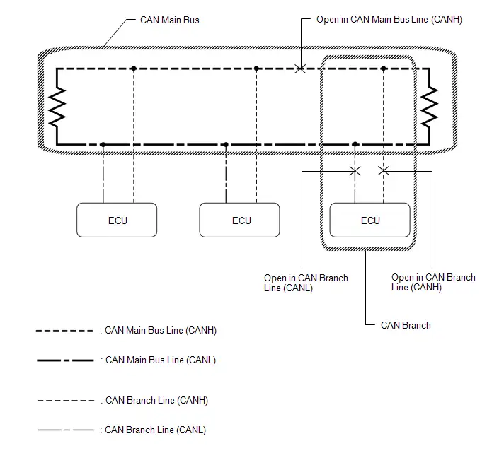
HINT:
- This waveform is measured between terminals CANH and GND, and terminals CANL and GND of the central gateway ECU (network gateway ECU). (Use this as a reference for diagnosis of CAN communication lines.)
- When malfunctions in multiple ECUs are suspected based on the CAN bus check and DTCs checked using the GTS, check the resistance of the CAN bus using an ohmmeter first. If no problems are found, check the following waveforms.
- If a waveform is not similar to one of the following 3 patterns (Group 1), then an open in a CAN main bus line, an open in a CAN branch line, or a short between a CAN line (CANH or CANL) and ground is suspected (Group 2).
- Wiggle the connector and wire harness to check if the waveform changes.
(a) CAN bus waveforms (Group 1)
(1) Normal waveform
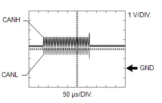
(2) Open in both of the lines (CANH and CANL) of a CAN branch
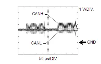
HINT:
- Waveforms (waveforms shown using dotted lines) are not output from an ECU or sensor connected to a CAN branch with an open circuit in both lines. (Waveforms from other ECUs or sensors are normal.)
- Because this waveform is similar to a normal waveform, instead of using the waveform, the malfunctioning part can be narrowed down by performing a CAN bus check.
(3) Short between the CAN bus lines (CANH and CANL)
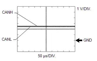
HINT:
- Waveforms disappear.
- If the malfunction is in an ECU, disconnecting the ECU will change the waveform. If the waveform does not change, a malfunction in the wire harness is suspected.
(b) CAN bus waveforms (reference) (Group 2)
NOTICE:
The following CAN bus waveforms can be used only as reference. The actual measured waveform may differ significantly depending on the location of the open or short circuit.
(1) Open in a CAN branch line (CANH)
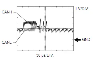
HINT:
- An abnormal waveform is output from an ECU with an open in one of its CAN branch lines. Because this abnormal output interferes with the signals from other ECUs, the output of other ECUs will also appear abnormal.
- Narrow down the malfunctioning part by checking DTCs or performing a CAN bus check, or by checking waveform changes when ECUs or sensors are disconnected. The waveform will change to one for an open in both sides of a CAN branch when the ECU or sensor with an open CAN branch line is disconnected.
(2) Open in a CAN branch line (CANL)
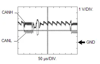
HINT:
- An abnormal waveform is output from an ECU with an open in one of its CAN branch lines. Because this abnormal output interferes with the signals from other ECUs, the output of other ECUs will also appear abnormal.
- Narrow down the malfunctioning part by checking DTCs or performing a CAN bus check, or by checking waveform changes when ECUs or sensors are disconnected. The waveform will change to one for an open in both sides of a CAN branch when the ECU or sensor with an open CAN branch line is disconnected.
(3) Open in a CAN main bus line (CANH)
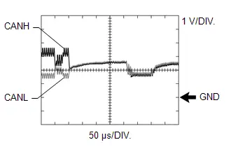
HINT:
- Waveforms of ECUs or sensors that are closer to the central gateway ECU (network gateway ECU) than the open part are almost normal.
- Waveforms of ECUs or sensors that are on the opposite side of the central gateway ECU (network gateway ECU) from the open part are abnormal.
- An open in a CAN main bus line can be confirmed by measuring the resistance between the CANH and CANL terminals of any CAN branch.
(4) Short between a CAN bus line (CANH) and ground
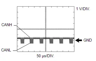
HINT:
- Narrow down the shorted part by checking for waveform changes when disconnecting connectors from the CAN junction connectors or when disconnecting ECUs or sensors.
- A short to ground in the CANH line can be confirmed by measuring the resistance between CANH and ground using an ohmmeter.
(5) Short between a CAN bus line (CANL) and ground
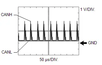
HINT:
- Narrow down the shorted part by checking for waveform changes when disconnecting connectors from the CAN junction connectors or when disconnecting ECUs or sensors.
- A short to ground in the CANL line can be confirmed by measuring the resistance between CANL and ground using an ohmmeter.
Data List / Active Test
DATA LIST / ACTIVE TEST
NOTICE:
In the table below, the values listed under "Normal Condition" are reference values. Do not depend solely on these reference values when deciding whether a part is faulty or not.
HINT:
Using the GTS to read the Data List allows the values or states of switches, sensors, actuators and other items to be read without removing any parts. This non-intrusive inspection can be very useful because intermittent conditions or signals may be discovered before parts or wiring is disturbed. Reading the Data List information early in troubleshooting is one way to save diagnostic time.
DATA LIST
(a) Read the Data List.
Body Electrical > Central Gateway > Data List| Tester Display |
|---|
| Total Distance Traveled |
| Total Distance Traveled - Unit |
| IG2 SW/IGR SW |
| IG1 SW/IGP SW |
| ACC SW |
| B Voltage |
| Tester Display | Measurement Item | Range | Normal Condition |
|---|---|---|---|
| Total Distance Traveled | Total distance traveled | Min.: 0 km (0 mile), Max.: 16777215 km (10425361 mile) | - |
| Total Distance Traveled - Unit | Total Distance Traveled unit | km or mile | - |
| IG2 SW/IGR SW | Ignition switch ON signal (IGR terminal) | OFF or ON | OFF: Ignition switch ACC or off ON: Ignition switch ON |
| IG1 SW/IGP SW | Ignition switch ON signal (IGP terminal) | OFF or ON | OFF: Ignition switch ACC or off ON: Ignition switch ON |
| ACC SW | Ignition switch ACC signal (ACC terminal) | OFF or ON | OFF: Ignition switch off ON: Ignition switch ACC or ON |
| B Voltage | Auxiliary battery voltage (BATT terminal) | Over 8 V or Under 8 V | Over 8 V: Auxiliary battery voltage 8 V or higher Under 8 V: Auxiliary battery voltage below 8 V |
Lost Communication with DC/DC Converter Control Module "C" Missing Message (U01BD87,U029100,U029187,U115087,U117687,U117B87)
DESCRIPTION
| DTC No. | Detection Item | DTC Detection Condition | Trouble Area | Note |
|---|---|---|---|---|
| U01BD87 | Lost Communication with DC/DC Converter Control Module "C" Missing Message | Communication stops between the hybrid Toyota Prius vehicle control ECU and the inverter with converter assembly. |
| DTC Output from
|
| U029100 | Lost Communication with Gear Shift Control Module "B" (System 2) Missing Message | Communication stops between the transmission floor shift assembly and the shift control actuator assembly. |
| DTC Output from
|
| U029187 | Lost Communication with Gear Shift Control Module "B" Missing Message | Communication stops between the hybrid Toyota Prius vehicle control ECU and the shift control actuator assembly. |
| DTC Output from
|
| U115087 | Lost Communication with Hybrid Powertrain Control Module (ch2) Missing Message | Communication stops between the battery ECU assembly and the hybrid Toyota Prius vehicle control ECU. |
| DTC Output from
|
| U117687 | Lost Communication with Gear Shift Control Module "A" (Powertrain Bus) Missing Message | Communication stops between the hybrid Toyota Prius vehicle control ECU and the transmission floor shift assembly. |
| DTC Output from
|
| U117B87 | Lost Communication with Hybrid/EV Battery Energy Control Module "A" (ch2) Missing Message | Communication stops between the hybrid Toyota Prius vehicle control ECU and the battery ECU assembly. |
| DTC Output from
|
WIRING DIAGRAM
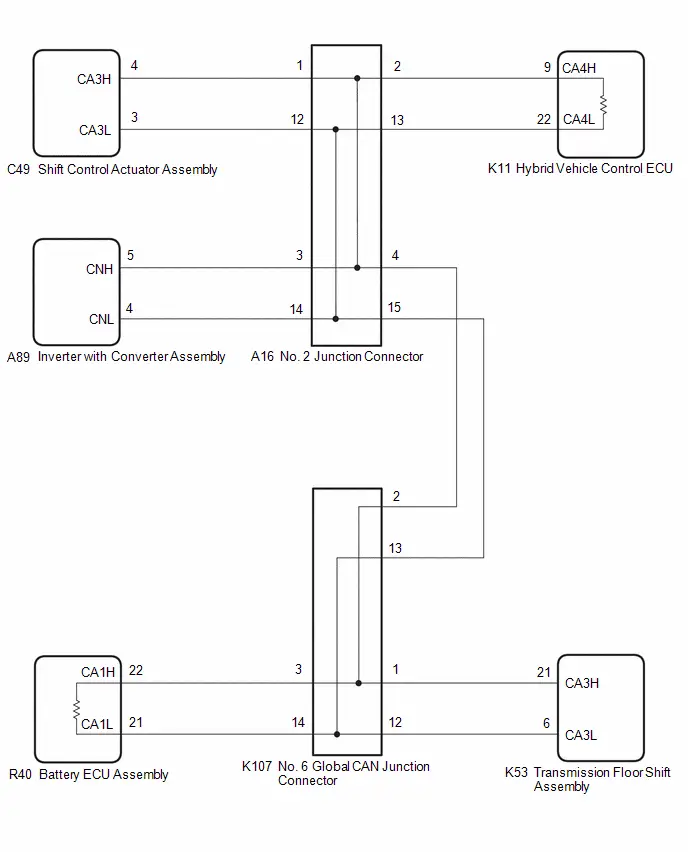
CAUTION / NOTICE / HINT
CAUTION:
When performing the confirmation driving pattern, obey all speed limits and traffic laws.
NOTICE:
-
Because the order of diagnosis is important to allow correct diagnosis, make sure to begin troubleshooting using How to Proceed with Troubleshooting when CAN communication system related DTCs are output.
Click here

- Before measuring the resistance of the CAN bus, turn the ignition switch off and leave the Toyota Prius vehicle for 1 minute or more without operating the key or any switches, or opening or closing the doors. After that, disconnect the cable from the negative (-) auxiliary battery terminal and leave the vehicle for 1 minute or more before measuring the resistance.
-
After the ignition switch is turned off, there may be a waiting time before disconnecting the negative (-) auxiliary battery terminal.
Click here

-
When disconnecting and reconnecting the auxiliary battery.
HINT:
When disconnecting and reconnecting the auxiliary battery, there is an automatic learning function that completes learning when the respective system is used.
Click here


-
Some parts must be initialized and set when replacing or removing and installing parts.
Click here


-
After performing repairs, perform the DTC check procedure and confirm that the DTCs are not output again.
DTC check procedure: Turn the ignition switch to ON and wait for 1 minute or more. Then operate the suspected malfunctioning system and drive the Toyota Prius vehicle at 60 km/h (37 mph) or more for 5 minutes or more.
-
After the repair, perform the CAN bus check and check that all the ECUs and sensors connected to the CAN communication system are displayed as normal.
Click here

-
Before replacing the hybrid Toyota Prius vehicle control ECU, refer to Registration.
Click here

- When disconnecting a wire harness of any component connected to the supply power of the integrated capacitor (integration control supply) or when removing the integrated capacitor (integration control supply), make sure to wait 5 minutes or more after turning the ignition switch off for self-diagnosis to complete and the voltage of the integrated capacitor (integration control supply) to discharge.
HINT:
- Before disconnecting related connectors for inspection, push in on each connector body to check that the connector is not loose or disconnected.
- When a connector is disconnected, check that the terminals and connector body are not cracked, deformed or corroded.
PROCEDURE
| 1. | CHECK FOR OPEN IN CAN MAIN BUS LINES |
(a) Disconnect the cable from the negative (-) auxiliary battery terminal.
(b) Measure the resistance according to the value(s) in the table below.
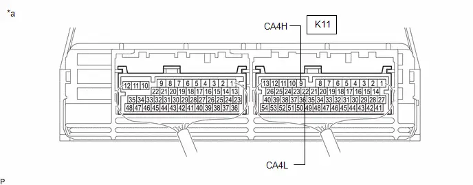
| *a | Component with harness connected (Hybrid Toyota Prius Vehicle Control ECU) | - | - |
Standard Resistance:
 Click Location & Routing(K11) Click Connector(K11)
 | Tester Connection | Condition | Specified Condition |
|---|---|---|
| K11-9 (CA4H) - K11-22 (CA4L) | Cable disconnected from negative (-) auxiliary battery terminal | Below 70 Ω |
| NG |

| GO TO STEP 41 |
|

| 2. | CHECK FOR SHORT IN CAN BUS LINES |
(a) Measure the resistance according to the value(s) in the table below.

| *a | Component with harness connected (Hybrid Toyota Prius Vehicle Control ECU) | - | - |
Standard Resistance:
 Click Location & Routing(K11) Click Connector(K11)
 | Tester Connection | Condition | Specified Condition |
|---|---|---|
| K11-9 (CA4H) - K11-22 (CA4L) | Cable disconnected from negative (-) auxiliary battery terminal | 54 Ω or higher |
| NG |

| GO TO STEP 29 |
|

| 3. | CHECK FOR SHORT TO B IN CAN BUS LINE |
(a) Measure the resistance according to the value(s) in the table below.
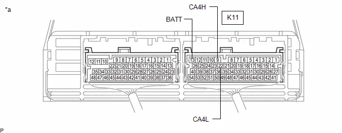
| *a | Component with harness connected (Hybrid Toyota Prius Vehicle Control ECU) | - | - |
Standard Resistance:
 Click Location & Routing(K11) Click Connector(K11)
 | Tester Connection | Condition | Specified Condition |
|---|---|---|
| K11-9 (CA4H) - K11-13 (BATT) | Cable disconnected from negative (-) auxiliary battery terminal | 6 kΩ or higher |
| K11-22 (CA4L) - K11-13 (BATT) |
| NG |

| GO TO STEP 17 |
|

| 4. | CHECK FOR SHORT TO GND IN CAN BUS LINE |
(a) Measure the resistance according to the value(s) in the table below.
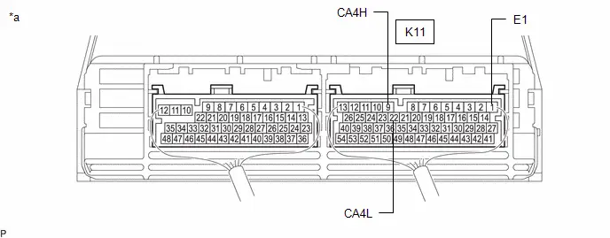
| *a | Component with harness connected (Hybrid Toyota Prius Vehicle Control ECU) | - | - |
Standard Resistance:
 Click Location & Routing(K11) Click Connector(K11)
 | Tester Connection | Condition | Specified Condition |
|---|---|---|
| K11-9 (CA4H) - K11-1 (E1) | Cable disconnected from negative (-) auxiliary battery terminal | 200 Ω or higher |
| K11-22 (CA4L) - K11-1 (E1) |
| OK |

| INSPECT FOR INTERMITTENT PROBLEMS |
|

| 5. | CHECK FOR SHORT TO GND IN CAN BUS LINE (NO. 2 JUNCTION CONNECTOR - HYBRID Toyota Prius Vehicle CONTROL ECU) |
(a) Disconnect the A16 No. 2 junction connector.
(b) Measure the resistance according to the value(s) in the table below.
Standard Resistance:
 Click Location & Routing(A16,K8) Click Connector(A16) Click Connector(K8)
 | Tester Connection | Condition | Specified Condition |
|---|---|---|
| A16-2 (CANH) - K8-4 (CG) | Cable disconnected from negative (-) auxiliary battery terminal | 200 Ω or higher |
| A16-13 (CANL) - K8-4 (CG) |
| NG |

| GO TO STEP 9 |
|

| 6. | CHECK FOR SHORT TO GND IN CAN BUS LINE (NO. 2 JUNCTION CONNECTOR - NO. 6 GLOBAL CAN JUNCTION CONNECTOR) |
(a) Measure the resistance according to the value(s) in the table below.
Standard Resistance:
 Click Location & Routing(A16,K8) Click Connector(A16) Click Connector(K8)
 | Tester Connection | Condition | Specified Condition |
|---|---|---|
| A16-4 (CANH) - K8-4 (CG) | Cable disconnected from negative (-) auxiliary battery terminal | 200 Ω or higher |
| A16-15 (CANL) - K8-4 (CG) |
| NG |

| GO TO STEP 12 |
|

| 7. | CHECK FOR SHORT TO GND IN CAN BUS LINE (NO. 2 JUNCTION CONNECTOR - SHIFT CONTROL ACTUATOR ASSEMBLY) |
(a) Measure the resistance according to the value(s) in the table below.
Standard Resistance:
 Click Location & Routing(A16,K8) Click Connector(A16) Click Connector(K8)
 | Tester Connection | Condition | Specified Condition |
|---|---|---|
| A16-1 (CANH) - K8-4 (CG) | Cable disconnected from negative (-) auxiliary battery terminal | 200 Ω or higher |
| A16-12 (CANL) - K8-4 (CG) |
| NG |

| GO TO STEP 10 |
|

| 8. | CHECK FOR SHORT TO GND IN CAN BUS LINE (NO. 2 JUNCTION CONNECTOR - INVERTER WITH CONVERTER ASSEMBLY) |
(a) Measure the resistance according to the value(s) in the table below.
Standard Resistance:
 Click Location & Routing(A16,K8) Click Connector(A16) Click Connector(K8)
 | Tester Connection | Condition | Specified Condition |
|---|---|---|
| A16-3 (CANH) - K8-4 (CG) | Cable disconnected from negative (-) auxiliary battery terminal | 200 Ω or higher |
| A16-14 (CANL) - K8-4 (CG) |
| OK |

| REPLACE NO. 2 JUNCTION CONNECTOR |
| NG |

| GO TO STEP 11 |
| 9. | CHECK FOR SHORT TO GND IN CAN BUS LINE (NO. 2 JUNCTION CONNECTOR - HYBRID Toyota Prius Vehicle CONTROL ECU) |
(a) Disconnect the K11 hybrid vehicle control ECU connector.
(b) Measure the resistance according to the value(s) in the table below.
Standard Resistance:
 Click Location & Routing(A16,K8) Click Connector(A16) Click Connector(K8)
 | Tester Connection | Condition | Specified Condition |
|---|---|---|
| A16-2 (CANH) - K8-4 (CG) | Cable disconnected from negative (-) auxiliary battery terminal | 200 Ω or higher |
| A16-13 (CANL) - K8-4 (CG) |
| OK |

| REPLACE HYBRID Toyota Prius Vehicle CONTROL ECU
|


| NG |

| REPAIR OR REPLACE CAN MAIN BUS LINE OR CONNECTOR (NO. 2 JUNCTION CONNECTOR - HYBRID Toyota Prius Vehicle CONTROL ECU) |
| 10. | CHECK FOR SHORT TO GND IN CAN BUS LINE (NO. 2 JUNCTION CONNECTOR - SHIFT CONTROL ACTUATOR ASSEMBLY) |
(a) Disconnect the C49 shift control actuator assembly connector.
(b) Measure the resistance according to the value(s) in the table below.
Standard Resistance:
 Click Location & Routing(A16,K8) Click Connector(A16) Click Connector(K8)
 | Tester Connection | Condition | Specified Condition |
|---|---|---|
| A16-1 (CANH) - K8-4 (CG) | Cable disconnected from negative (-) auxiliary battery terminal | 200 Ω or higher |
| A16-12 (CANL) - K8-4 (CG) |
| OK |

| REPLACE SHIFT CONTROL ACTUATOR ASSEMBLY |
| NG |

| REPAIR OR REPLACE CAN BRANCH LINE OR CONNECTOR (NO. 2 JUNCTION CONNECTOR - SHIFT CONTROL ACTUATOR ASSEMBLY) |
| 11. | CHECK FOR SHORT TO GND IN CAN BUS LINE (NO. 2 JUNCTION CONNECTOR - INVERTER WITH CONVERTER ASSEMBLY) |
(a) Disconnect the A89 inverter with converter assembly connector.
(b) Measure the resistance according to the value(s) in the table below.
Standard Resistance:
 Click Location & Routing(A16,K8) Click Connector(A16) Click Connector(K8)
 | Tester Connection | Condition | Specified Condition |
|---|---|---|
| A16-3 (CANH) - K8-4 (CG) | Cable disconnected from negative (-) auxiliary battery terminal | 200 Ω or higher |
| A16-14 (CANL) - K8-4 (CG) |
| OK |

| REPLACE INVERTER WITH CONVERTER ASSEMBLY |
| NG |

| REPAIR OR REPLACE CAN BRANCH LINE OR CONNECTOR (NO. 2 JUNCTION CONNECTOR - INVERTER WITH CONVERTER ASSEMBLY) |
| 12. | CHECK FOR SHORT TO GND IN CAN BUS LINE (NO. 6 GLOBAL CAN JUNCTION CONNECTOR - NO. 2 JUNCTION CONNECTOR) |
(a) Disconnect the K107 No. 6 Global CAN junction connector.
(b) Measure the resistance according to the value(s) in the table below.
Standard Resistance:
 Click Location & Routing(K107,K8) Click Connector(K107) Click Connector(K8)
 | Tester Connection | Condition | Specified Condition |
|---|---|---|
| K107-2 (CANH) - K8-4 (CG) | Cable disconnected from negative (-) auxiliary battery terminal | 200 Ω or higher |
| K107-13 (CANL) - K8-4 (CG) |
| NG |

| REPAIR OR REPLACE CAN MAIN BUS LINES OR CONNECTOR (NO. 6 GLOBAL CAN JUNCTION CONNECTOR - NO. 2 JUNCTION CONNECTOR) |
|

| 13. | CHECK FOR SHORT TO GND IN CAN BUS LINE (NO. 6 GLOBAL CAN JUNCTION CONNECTOR - BATTERY ECU ASSEMBLY) |
(a) Measure the resistance according to the value(s) in the table below.
Standard Resistance:
 Click Location & Routing(K107,K8) Click Connector(K107) Click Connector(K8)
 | Tester Connection | Condition | Specified Condition |
|---|---|---|
| K107-3 (CANH) - K8-4 (CG) | Cable disconnected from negative (-) auxiliary battery terminal | 200 Ω or higher |
| K107-14 (CANL) - K8-4 (CG) |
| NG |

| GO TO STEP 15 |
|

| 14. | CHECK FOR SHORT TO GND IN CAN BUS LINE (NO. 6 GLOBAL CAN JUNCTION CONNECTOR - TRANSMISSION FLOOR SHIFT ASSEMBLY) |
(a) Measure the resistance according to the value(s) in the table below.
Standard Resistance:
 Click Location & Routing(K107,K8) Click Connector(K107) Click Connector(K8)
 | Tester Connection | Condition | Specified Condition |
|---|---|---|
| K107-1 (CANH) - K8-4 (CG) | Cable disconnected from negative (-) auxiliary battery terminal | 200 Ω or higher |
| K107-12 (CANL) - K8-4 (CG) |
| OK |

| REPLACE NO. 6 GLOBAL CAN JUNCTION CONNECTOR |
| NG |

| GO TO STEP 16 |
| 15. | CHECK FOR SHORT TO GND IN CAN BUS LINE (NO. 6 GLOBAL CAN JUNCTION CONNECTOR - BATTERY ECU ASSEMBLY) |
(a) Disconnect the R40 battery ECU assembly connector.
(b) Measure the resistance according to the value(s) in the table below.
Standard Resistance:
 Click Location & Routing(K107,K8) Click Connector(K107) Click Connector(K8)
 | Tester Connection | Condition | Specified Condition |
|---|---|---|
| K107-3 (CANH) - K8-4 (CG) | Cable disconnected from negative (-) auxiliary battery terminal | 200 Ω or higher |
| K107-14 (CANL) - K8-4 (CG) |
| OK |

| REPLACE BATTERY ECU ASSEMBLY |
| NG |

| REPAIR OR REPLACE CAN MAIN BUS LINE OR CONNECTOR (NO. 6 GLOBAL CAN JUNCTION CONNECTOR - BATTERY ECU ASSEMBLY) |
| 16. | CHECK FOR SHORT TO GND IN CAN BUS LINE (NO. 6 GLOBAL CAN JUNCTION CONNECTOR - TRANSMISSION FLOOR SHIFT ASSEMBLY) |
(a) Disconnect the K53 transmission floor shift assembly connector.
(b) Measure the resistance according to the value(s) in the table below.
Standard Resistance:
 Click Location & Routing(K107,K8) Click Connector(K107) Click Connector(K8)
 | Tester Connection | Condition | Specified Condition |
|---|---|---|
| K107-1 (CANH) - K8-4 (CG) | Cable disconnected from negative (-) auxiliary battery terminal | 200 Ω or higher |
| K107-12 (CANL) - K8-4 (CG) |
| OK |

| REPLACE TRANSMISSION FLOOR SHIFT ASSEMBLY |
| NG |

| REPAIR OR REPLACE CAN BRANCH LINE OR CONNECTOR (NO. 6 GLOBAL CAN JUNCTION CONNECTOR - TRANSMISSION FLOOR SHIFT ASSEMBLY) |
| 17. | CHECK FOR SHORT TO B IN CAN BUS LINE (NO. 2 JUNCTION CONNECTOR - HYBRID Toyota Prius Vehicle CONTROL ECU) |
(a) Disconnect the A16 No. 2 junction connector.
(b) Measure the resistance according to the value(s) in the table below.
Standard Resistance:
 Click Location & Routing(A16,K8) Click Connector(A16) Click Connector(K8)
 | Tester Connection | Condition | Specified Condition |
|---|---|---|
| A16-2 (CANH) - K8-16 (BAT) | Cable disconnected from negative (-) auxiliary battery terminal | 6 kΩ or higher |
| A16-13 (CANL) - K8-16 (BAT) |
| NG |

| GO TO STEP 21 |
|

| 18. | CHECK FOR SHORT TO B IN CAN BUS LINE (NO. 2 JUNCTION CONNECTOR - NO. 6 GLOBAL CAN JUNCTION CONNECTOR) |
(a) Measure the resistance according to the value(s) in the table below.
Standard Resistance:
 Click Location & Routing(A16,K8) Click Connector(A16) Click Connector(K8)
 | Tester Connection | Condition | Specified Condition |
|---|---|---|
| A16-4 (CANH) - K8-16 (BAT) | Cable disconnected from negative (-) auxiliary battery terminal | 6 kΩ or higher |
| A16-15 (CANL) - K8-16 (BAT) |
| NG |

| GO TO STEP 24 |
|

| 19. | CHECK FOR SHORT TO B IN CAN BUS LINE (NO. 2 JUNCTION CONNECTOR - SHIFT CONTROL ACTUATOR ASSEMBLY) |
(a) Measure the resistance according to the value(s) in the table below.
Standard Resistance:
 Click Location & Routing(A16,K8) Click Connector(A16) Click Connector(K8)
 | Tester Connection | Condition | Specified Condition |
|---|---|---|
| A16-1 (CANH) - K8-16 (BAT) | Cable disconnected from negative (-) auxiliary battery terminal | 6 kΩ or higher |
| A16-12 (CANL) - K8-16 (BAT) |
| NG |

| GO TO STEP 22 |
|

| 20. | CHECK FOR SHORT TO B IN CAN BUS LINE (NO. 2 JUNCTION CONNECTOR - INVERTER WITH CONVERTER ASSEMBLY) |
(a) Measure the resistance according to the value(s) in the table below.
Standard Resistance:
 Click Location & Routing(A16,K8) Click Connector(A16) Click Connector(K8)
 | Tester Connection | Condition | Specified Condition |
|---|---|---|
| A16-3 (CANH) - K8-16 (BAT) | Cable disconnected from negative (-) auxiliary battery terminal | 6 kΩ or higher |
| A16-14 (CANL) - K8-16 (BAT) |
| OK |

| REPLACE NO. 2 JUNCTION CONNECTOR |
| NG |

| GO TO STEP 23 |
| 21. | CHECK FOR SHORT TO B IN CAN BUS LINE (NO. 2 JUNCTION CONNECTOR - HYBRID Toyota Prius Vehicle CONTROL ECU) |
(a) Disconnect the K11 hybrid vehicle control ECU connector.
(b) Measure the resistance according to the value(s) in the table below.
Standard Resistance:
 Click Location & Routing(A16,K8) Click Connector(A16) Click Connector(K8)
 | Tester Connection | Condition | Specified Condition |
|---|---|---|
| A16-2 (CANH) - K8-16 (BAT) | Cable disconnected from negative (-) auxiliary battery terminal | 6 kΩ or higher |
| A16-13 (CANL) - K8-16 (BAT) |
| OK |

| REPLACE HYBRID Toyota Prius Vehicle CONTROL ECU
|


| NG |

| REPAIR OR REPLACE CAN MAIN BUS LINE OR CONNECTOR (NO. 2 JUNCTION CONNECTOR - HYBRID Toyota Prius Vehicle CONTROL ECU) |
| 22. | CHECK FOR SHORT TO B IN CAN BUS LINE (NO. 2 JUNCTION CONNECTOR - SHIFT CONTROL ACTUATOR ASSEMBLY) |
(a) Disconnect the C49 shift control actuator assembly connector.
(b) Measure the resistance according to the value(s) in the table below.
Standard Resistance:
 Click Location & Routing(A16,K8) Click Connector(A16) Click Connector(K8)
 | Tester Connection | Condition | Specified Condition |
|---|---|---|
| A16-1 (CANH) - K8-16 (BAT) | Cable disconnected from negative (-) auxiliary battery terminal | 6 kΩ or higher |
| A16-12 (CANL) - K8-16 (BAT) |
| OK |

| REPLACE SHIFT CONTROL ACTUATOR ASSEMBLY |
| NG |

| REPAIR OR REPLACE CAN BRANCH LINE OR CONNECTOR (NO. 2 JUNCTION CONNECTOR - SHIFT CONTROL ACTUATOR ASSEMBLY) |
| 23. | CHECK FOR SHORT TO B IN CAN BUS LINE (NO. 2 JUNCTION CONNECTOR - INVERTER WITH CONVERTER ASSEMBLY) |
(a) Disconnect the A89 inverter with converter assembly connector.
(b) Measure the resistance according to the value(s) in the table below.
Standard Resistance:
 Click Location & Routing(A16,K8) Click Connector(A16) Click Connector(K8)
 | Tester Connection | Condition | Specified Condition |
|---|---|---|
| A16-3 (CANH) - K8-16 (BAT) | Cable disconnected from negative (-) auxiliary battery terminal | 6 kΩ or higher |
| A16-14 (CANL) - K8-16 (BAT) |
| OK |

| REPLACE INVERTER WITH CONVERTER ASSEMBLY |
| NG |

| REPAIR OR REPLACE CAN BRANCH LINE OR CONNECTOR (NO. 2 JUNCTION CONNECTOR - INVERTER WITH CONVERTER ASSEMBLY) |
| 24. | CHECK FOR SHORT TO B IN CAN BUS LINE (NO. 6 GLOBAL CAN JUNCTION CONNECTOR - NO. 2 JUNCTION CONNECTOR) |
(a) Disconnect the K107 No. 6 Global CAN junction connector.
(b) Measure the resistance according to the value(s) in the table below.
Standard Resistance:
 Click Location & Routing(K107,K8) Click Connector(K107) Click Connector(K8)
 | Tester Connection | Condition | Specified Condition |
|---|---|---|
| K107-2 (CANH) - K8-16 (BAT) | Cable disconnected from negative (-) auxiliary battery terminal | 6 kΩ or higher |
| K107-13 (CANL) - K8-16 (BAT) |
| NG |

| REPAIR OR REPLACE CAN MAIN BUS LINES OR CONNECTOR (NO. 6 GLOBAL CAN JUNCTION CONNECTOR - NO. 2 JUNCTION CONNECTOR) |
|

| 25. | CHECK FOR SHORT TO B IN CAN BUS LINE (NO. 6 GLOBAL CAN JUNCTION CONNECTOR - BATTERY ECU ASSEMBLY) |
(a) Measure the resistance according to the value(s) in the table below.
Standard Resistance:
 Click Location & Routing(K107,K8) Click Connector(K107) Click Connector(K8)
 | Tester Connection | Condition | Specified Condition |
|---|---|---|
| K107-3 (CANH) - K8-16 (BAT) | Cable disconnected from negative (-) auxiliary battery terminal | 6 kΩ or higher |
| K107-14 (CANL) - K8-16 (BAT) |
| NG |

| GO TO STEP 27 |
|

| 26. | CHECK FOR SHORT TO B IN CAN BUS LINE (NO. 6 GLOBAL CAN JUNCTION CONNECTOR - TRANSMISSION FLOOR SHIFT ASSEMBLY) |
(a) Measure the resistance according to the value(s) in the table below.
Standard Resistance:
 Click Location & Routing(K107,K8) Click Connector(K107) Click Connector(K8)
 | Tester Connection | Condition | Specified Condition |
|---|---|---|
| K107-1 (CANH) - K8-16 (BAT) | Cable disconnected from negative (-) auxiliary battery terminal | 6 kΩ or higher |
| K107-12 (CANL) - K8-16 (BAT) |
| OK |

| REPLACE NO. 6 GLOBAL CAN JUNCTION CONNECTOR |
| NG |

| GO TO STEP 28 |
| 27. | CHECK FOR SHORT TO B IN CAN BUS LINE (NO. 6 GLOBAL CAN JUNCTION CONNECTOR - BATTERY ECU ASSEMBLY) |
(a) Disconnect the R40 battery ECU assembly connector.
(b) Measure the resistance according to the value(s) in the table below.
Standard Resistance:
 Click Location & Routing(K107,K8) Click Connector(K107) Click Connector(K8)
 | Tester Connection | Condition | Specified Condition |
|---|---|---|
| K107-3 (CANH) - K8-16 (BAT) | Cable disconnected from negative (-) auxiliary battery terminal | 6 kΩ or higher |
| K107-14 (CANL) - K8-16 (BAT) |
| OK |

| REPLACE BATTERY ECU ASSEMBLY |
| NG |

| REPAIR OR REPLACE CAN MAIN BUS LINE OR CONNECTOR (NO. 6 GLOBAL CAN JUNCTION CONNECTOR - BATTERY ECU ASSEMBLY) |
| 28. | CHECK FOR SHORT TO B IN CAN BUS LINE (NO. 6 GLOBAL CAN JUNCTION CONNECTOR - TRANSMISSION FLOOR SHIFT ASSEMBLY) |
(a) Disconnect the K53 transmission floor shift assembly connector.
(b) Measure the resistance according to the value(s) in the table below.
Standard Resistance:
 Click Location & Routing(K107,K8) Click Connector(K107) Click Connector(K8)
 | Tester Connection | Condition | Specified Condition |
|---|---|---|
| K107-1 (CANH) - K8-16 (BAT) | Cable disconnected from negative (-) auxiliary battery terminal | 6 kΩ or higher |
| K107-12 (CANL) - K8-16 (BAT) |
| OK |

| REPLACE TRANSMISSION FLOOR SHIFT ASSEMBLY |
| NG |

| REPAIR OR REPLACE CAN BRANCH LINE OR CONNECTOR (NO. 6 GLOBAL CAN JUNCTION CONNECTOR - TRANSMISSION FLOOR SHIFT ASSEMBLY) |
| 29. | CHECK FOR SHORT IN CAN BUS LINES (NO. 2 JUNCTION CONNECTOR - HYBRID Toyota Prius Vehicle CONTROL ECU) |
(a) Disconnect the A16 No. 2 junction connector.
(b) Measure the resistance according to the value(s) in the table below.
Standard Resistance:
 Click Location & Routing(A16) Click Connector(A16)
 | Tester Connection | Condition | Specified Condition |
|---|---|---|
| A16-2 (CANH) - A16-13 (CANL) | Cable disconnected from negative (-) auxiliary battery terminal | 108 to 132 Ω |
| NG |

| GO TO STEP 33 |
|

| 30. | CHECK FOR SHORT IN CAN BUS LINES (NO. 2 JUNCTION CONNECTOR - NO. 6 GLOBAL CAN JUNCTION CONNECTOR) |
(a) Measure the resistance according to the value(s) in the table below.
Standard Resistance:
 Click Location & Routing(A16) Click Connector(A16)
 | Tester Connection | Condition | Specified Condition |
|---|---|---|
| A16-4 (CANH) - A16-15 (CANL) | Cable disconnected from negative (-) auxiliary battery terminal | 108 to 132 Ω |
| NG |

| GO TO STEP 36 |
|

| 31. | CHECK FOR SHORT IN CAN BUS LINES (NO. 2 JUNCTION CONNECTOR - SHIFT CONTROL ACTUATOR ASSEMBLY) |
(a) Measure the resistance according to the value(s) in the table below.
Standard Resistance:
 Click Location & Routing(A16) Click Connector(A16)
 | Tester Connection | Condition | Specified Condition |
|---|---|---|
| A16-1 (CANH) - A16-12 (CANL) | Cable disconnected from negative (-) auxiliary battery terminal | 200 Ω or higher |
| NG |

| GO TO STEP 34 |
|

| 32. | CHECK FOR SHORT IN CAN BUS LINES (NO. 2 JUNCTION CONNECTOR - INVERTER WITH CONVERTER ASSEMBLY) |
(a) Measure the resistance according to the value(s) in the table below.
Standard Resistance:
 Click Location & Routing(A16) Click Connector(A16)
 | Tester Connection | Condition | Specified Condition |
|---|---|---|
| A16-3 (CANH) - A16-14 (CANL) | Cable disconnected from negative (-) auxiliary battery terminal | 200 Ω or higher |
| OK |

| REPLACE NO. 2 JUNCTION CONNECTOR |
| NG |

| GO TO STEP 35 |
| 33. | CHECK FOR SHORT IN CAN BUS LINES (NO. 2 JUNCTION CONNECTOR - HYBRID Toyota Prius Vehicle CONTROL ECU) |
(a) Disconnect the K11 hybrid vehicle control ECU connector.
(b) Measure the resistance according to the value(s) in the table below.
Standard Resistance:
 Click Location & Routing(A16) Click Connector(A16)
 | Tester Connection | Condition | Specified Condition |
|---|---|---|
| A16-2 (CANH) - A16-13 (CANL) | Cable disconnected from negative (-) auxiliary battery terminal | 1 MΩ or higher |
| OK |

| REPLACE HYBRID Toyota Prius Vehicle CONTROL ECU
|


| NG |

| REPAIR OR REPLACE CAN MAIN BUS LINES OR CONNECTOR (NO. 2 JUNCTION CONNECTOR - HYBRID Toyota Prius Vehicle CONTROL ECU) |
| 34. | CHECK FOR SHORT IN CAN BUS LINES (NO. 2 JUNCTION CONNECTOR - SHIFT CONTROL ACTUATOR ASSEMBLY) |
(a) Disconnect the C49 shift control actuator assembly connector.
(b) Measure the resistance according to the value(s) in the table below.
Standard Resistance:
 Click Location & Routing(A16) Click Connector(A16)
 | Tester Connection | Condition | Specified Condition |
|---|---|---|
| A16-1 (CANH) - A16-12 (CANL) | Cable disconnected from negative (-) auxiliary battery terminal | 1 MΩ or higher |
| OK |

| REPLACE SHIFT CONTROL ACTUATOR ASSEMBLY |
| NG |

| REPAIR OR REPLACE CAN BRANCH LINES OR CONNECTOR (NO. 2 JUNCTION CONNECTOR - SHIFT CONTROL ACTUATOR ASSEMBLY) |
| 35. | CHECK FOR SHORT IN CAN BUS LINES (NO. 2 JUNCTION CONNECTOR - INVERTER WITH CONVERTER ASSEMBLY) |
(a) Disconnect the A89 inverter with converter assembly connector.
(b) Measure the resistance according to the value(s) in the table below.
Standard Resistance:
 Click Location & Routing(A16) Click Connector(A16)
 | Tester Connection | Condition | Specified Condition |
|---|---|---|
| A16-3 (CANH) - A16-14 (CANL) | Cable disconnected from negative (-) auxiliary battery terminal | 1 MΩ or higher |
| OK |

| REPLACE INVERTER WITH CONVERTER ASSEMBLY |
| NG |

| REPAIR OR REPLACE CAN BRANCH LINES OR CONNECTOR (NO. 2 JUNCTION CONNECTOR - INVERTER WITH CONVERTER ASSEMBLY) |
| 36. | CHECK FOR SHORT IN CAN BUS LINES (NO. 6 GLOBAL CAN JUNCTION CONNECTOR - NO. 2 JUNCTION CONNECTOR) |
(a) Reconnect the A16 No. 2 junction connector.
(b) Disconnect the K107 No. 6 Global CAN junction connector.
(c) Measure the resistance according to the value(s) in the table below.
Standard Resistance:
 Click Location & Routing(K107) Click Connector(K107)
 | Tester Connection | Condition | Specified Condition |
|---|---|---|
| K107-2 (CANH) - K107-13 (CANL) | Cable disconnected from negative (-) auxiliary battery terminal | 108 to 132 Ω |
| NG |

| REPAIR OR REPLACE CAN MAIN BUS LINES OR CONNECTOR (NO. 6 GLOBAL CAN JUNCTION CONNECTOR - NO. 2 JUNCTION CONNECTOR) |
|

| 37. | CHECK FOR SHORT IN CAN BUS LINES (NO. 6 GLOBAL CAN JUNCTION CONNECTOR - BATTERY ECU ASSEMBLY) |
(a) Measure the resistance according to the value(s) in the table below.
Standard Resistance:
 Click Location & Routing(K107) Click Connector(K107)
 | Tester Connection | Condition | Specified Condition |
|---|---|---|
| K107-3 (CANH) - K107-14 (CANL) | Cable disconnected from negative (-) auxiliary battery terminal | 108 to 132 Ω |
| NG |

| GO TO STEP 39 |
|

| 38. | CHECK FOR SHORT IN CAN BUS LINES (NO. 6 GLOBAL CAN JUNCTION CONNECTOR - TRANSMISSION FLOOR SHIFT ASSEMBLY) |
(a) Measure the resistance according to the value(s) in the table below.
Standard Resistance:
 Click Location & Routing(K107) Click Connector(K107)
 | Tester Connection | Condition | Specified Condition |
|---|---|---|
| K107-1 (CANH) - K107-12 (CANL) | Cable disconnected from negative (-) auxiliary battery terminal | 200 Ω or higher |
| OK |

| REPLACE NO. 6 GLOBAL CAN JUNCTION CONNECTOR |
| NG |

| GO TO STEP 40 |
| 39. | CHECK FOR SHORT IN CAN BUS LINES (NO. 6 GLOBAL CAN JUNCTION CONNECTOR - BATTERY ECU ASSEMBLY) |
(a) Disconnect the R40 battery ECU assembly connector.
(b) Measure the resistance according to the value(s) in the table below.
Standard Resistance:
 Click Location & Routing(K107) Click Connector(K107)
 | Tester Connection | Condition | Specified Condition |
|---|---|---|
| K107-3 (CANH) - K107-14 (CANL) | Cable disconnected from negative (-) auxiliary battery terminal | 1 MΩ or higher |
| OK |

| REPLACE BATTERY ECU ASSEMBLY |
| NG |

| REPAIR OR REPLACE CAN MAIN BUS LINES OR CONNECTOR (NO. 6 GLOBAL CAN JUNCTION CONNECTOR - BATTERY ECU ASSEMBLY) |
| 40. | CHECK FOR SHORT IN CAN BUS LINES (NO. 6 GLOBAL CAN JUNCTION CONNECTOR - TRANSMISSION FLOOR SHIFT ASSEMBLY) |
(a) Disconnect the K53 transmission floor shift assembly connector.
(b) Measure the resistance according to the value(s) in the table below.
Standard Resistance:
 Click Location & Routing(K107) Click Connector(K107)
 | Tester Connection | Condition | Specified Condition |
|---|---|---|
| K107-1 (CANH) - K107-12 (CANL) | Cable disconnected from negative (-) auxiliary battery terminal | 1 MΩ or higher |
| OK |

| REPLACE TRANSMISSION FLOOR SHIFT ASSEMBLY |
| NG |

| REPAIR OR REPLACE CAN BRANCH LINES OR CONNECTOR (NO. 6 GLOBAL CAN JUNCTION CONNECTOR - TRANSMISSION FLOOR SHIFT ASSEMBLY) |
| 41. | CHECK FOR OPEN IN CAN MAIN BUS LINES (HYBRID Toyota Prius Vehicle CONTROL ECU) |
(a) Disconnect the K11 hybrid vehicle control ECU connector.
(b) Measure the resistance according to the value(s) in the table below.
Standard Resistance:
 Click Location & Routing(K11) Click Connector(K11)
 | Tester Connection | Condition | Specified Condition |
|---|---|---|
| K11-9 (CA4H) - K11-22 (CA4L) | Cable disconnected from negative (-) auxiliary battery terminal | 108 to 132 Ω |
| OK |

| REPLACE HYBRID Toyota Prius Vehicle CONTROL ECU
|


|

| 42. | CHECK FOR OPEN IN CAN MAIN BUS LINES (NO. 2 JUNCTION CONNECTOR - HYBRID Toyota Prius Vehicle CONTROL ECU) |
(a) Reconnect the K11 hybrid vehicle control ECU connector.
(b) Disconnect the A16 No. 2 junction connector.
(c) Measure the resistance according to the value(s) in the table below.
Standard Resistance:
 Click Location & Routing(A16) Click Connector(A16)
 | Tester Connection | Condition | Specified Condition |
|---|---|---|
| A16-2 (CANH) - A16-13 (CANL) | Cable disconnected from negative (-) auxiliary battery terminal | 108 to 132 Ω |
| NG |

| REPAIR OR REPLACE CAN MAIN BUS LINES OR CONNECTOR (NO. 2 JUNCTION CONNECTOR - HYBRID Toyota Prius Vehicle CONTROL ECU) |
|

| 43. | CHECK FOR OPEN IN CAN MAIN BUS LINES (NO. 2 JUNCTION CONNECTOR - NO. 6 GLOBAL CAN JUNCTION CONNECTOR) |
(a) Measure the resistance according to the value(s) in the table below.
Standard Resistance:
 Click Location & Routing(A16) Click Connector(A16)
 | Tester Connection | Condition | Specified Condition |
|---|---|---|
| A16-4 (CANH) - A16-15 (CANL) | Cable disconnected from negative (-) auxiliary battery terminal | 108 to 132 Ω |
| OK |

| REPLACE NO. 2 JUNCTION CONNECTOR |
|

| 44. | CHECK FOR OPEN IN CAN MAIN BUS LINES (NO. 6 GLOBAL CAN JUNCTION CONNECTOR - NO. 2 JUNCTION CONNECTOR) |
(a) Reconnect the A16 No. 2 junction connector.
(b) Disconnect the K107 No. 6 Global CAN junction connector.
(c) Measure the resistance according to the value(s) in the table below.
Standard Resistance:
 Click Location & Routing(K107) Click Connector(K107)
 | Tester Connection | Condition | Specified Condition |
|---|---|---|
| K107-2 (CANH) - K107-13 (CANL) | Cable disconnected from negative (-) auxiliary battery terminal | 108 to 132 Ω |
| NG |

| REPAIR OR REPLACE CAN MAIN BUS LINES OR CONNECTOR (NO. 6 GLOBAL CAN JUNCTION CONNECTOR - NO. 2 JUNCTION CONNECTOR) |
|

| 45. | CHECK FOR OPEN IN CAN MAIN BUS LINES (NO. 6 GLOBAL CAN JUNCTION CONNECTOR - BATTERY ECU ASSEMBLY) |
(a) Measure the resistance according to the value(s) in the table below.
Standard Resistance:
 Click Location & Routing(K107) Click Connector(K107)
 | Tester Connection | Condition | Specified Condition |
|---|---|---|
| K107-3 (CANH) - K107-14 (CANL) | Cable disconnected from negative (-) auxiliary battery terminal | 108 to 132 Ω |
| OK |

| REPLACE NO. 6 GLOBAL CAN JUNCTION CONNECTOR |
|

| 46. | CHECK FOR OPEN IN CAN MAIN BUS LINES (BATTERY ECU ASSEMBLY) |
(a) Reconnect the K107 No. 6 Global CAN junction connector.
(b) Disconnect the R40 battery ECU assembly connector.
(c) Measure the resistance according to the value(s) in the table below.
Standard Resistance:
 Click Location & Routing(R40) Click Connector(R40)
 | Tester Connection | Condition | Specified Condition |
|---|---|---|
| R40-22 (CA1H) - R40-21 (CA1L) | Cable disconnected from negative (-) auxiliary battery terminal | 108 to 132 Ω |
| OK |

| REPLACE BATTERY ECU ASSEMBLY |
| NG |

| REPAIR OR REPLACE CAN MAIN BUS LINES OR CONNECTOR (BATTERY ECU ASSEMBLY - NO. 6 GLOBAL CAN JUNCTION CONNECTOR) |
Lost Communication with ECM/PCM "A" (ch2) Missing Message (U111A87,U115000,U115087,U115487,U115987,U117008,U117087,U117D87,U11BC87)
DESCRIPTION
| DTC No. | Detection Item | DTC Detection Condition | Trouble Area | Note |
|---|---|---|---|---|
| U111A87 | Lost Communication with ECM/PCM "A" (ch2) Missing Message | Communication stops between the hybrid Toyota Prius vehicle control ECU or No. 2 skid control ECU (brake actuator assembly) and the ECM. |
| DTC Output from
|
| U115000 | Lost Communication with Hybrid Powertrain Control Module (ch2) | Communication stops between the No. 1 skid control ECU (brake booster with master cylinder assembly) and the hybrid Toyota Prius vehicle control ECU. |
| DTC Output from
|
| U115087 | Lost Communication with Hybrid Powertrain Control Module (ch2) Missing Message | Communication stops between the ECM or No. 2 skid control ECU (brake actuator assembly) and the hybrid Toyota Prius vehicle control ECU. |
| DTC Output from
|
| U115487 | Lost Communication with Drive Motor Control Module "A" (ch2) Missing Message | Communication stops between the ECM or hybrid Toyota Prius vehicle control ECU and the inverter with converter assembly. |
| DTC Output from
|
| U115987 | Lost Communication with Electronic Brake Booster Control Module "A" (ch3) Missing Message | Communication stops between the No. 2 skid control ECU (brake actuator assembly) and the No. 1 skid control ECU (brake booster with master cylinder assembly). |
| DTC Output from
|
| U117008 | Lost Communication with Brake System Control Module (ch2) Bus Signal / Message Failure | Communication stops between the hybrid Toyota Prius vehicle control ECU or inverter with converter assembly and the No. 2 skid control ECU (brake actuator assembly). |
| DTC Output from
|
| U117087 | Lost Communication with Brake System Control Module (ch2) Missing Message | Communication stops between the inverter with converter assembly or hybrid Toyota Prius vehicle control ECU and the No. 2 skid control ECU (brake actuator assembly). |
| DTC Output from
|
| U117D87 | Lost Communication with Brake System Control Module (ch4) Missing Message | Communication stops between the No. 1 skid control ECU (brake booster with master cylinder assembly) and the No. 2 skid control ECU (brake actuator assembly). |
| DTC Output from
|
| U11BC87 | Lost Communication with Hybrid/EV Powertrain Control Module (ch6) Missing Message | Communication stops between the hybrid Toyota Prius vehicle control ECU and the No. 2 skid control ECU (brake actuator assembly). |
| DTC Output from
|
WIRING DIAGRAM
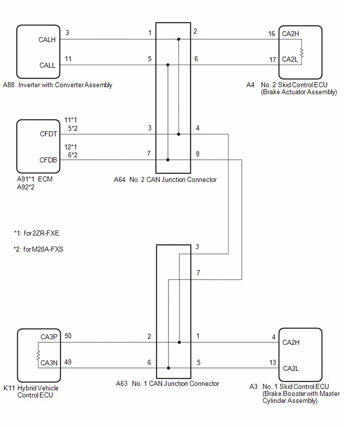
CAUTION / NOTICE / HINT
CAUTION:
When performing the confirmation driving pattern, obey all speed limits and traffic laws.
NOTICE:
-
Because the order of diagnosis is important to allow correct diagnosis, make sure to begin troubleshooting using How to Proceed with Troubleshooting when CAN communication system related DTCs are output.
Click here

- Before measuring the resistance of the CAN bus, turn the ignition switch off and leave the Toyota Prius vehicle for 1 minute or more without operating the key or any switches, or opening or closing the doors. After that, disconnect the cable from the negative (-) auxiliary battery terminal and leave the vehicle for 1 minute or more before measuring the resistance.
-
After the ignition switch is turned off, there may be a waiting time before disconnecting the negative (-) auxiliary battery terminal.
Click here

-
When disconnecting and reconnecting the auxiliary battery.
HINT:
When disconnecting and reconnecting the auxiliary battery, there is an automatic learning function that completes learning when the respective system is used.
Click here


-
Some parts must be initialized and set when replacing or removing and installing parts.
Click here


-
After performing repairs, perform the DTC check procedure and confirm that the DTCs are not output again.
DTC check procedure: Turn the ignition switch to ON and wait for 1 minute or more. Then operate the suspected malfunctioning system and drive the Toyota Prius vehicle at 60 km/h (37 mph) or more for 5 minutes or more.
-
After the repair, perform the CAN bus check and check that all the ECUs and sensors connected to the CAN communication system are displayed as normal.
Click here

-
Before replacing the hybrid Toyota Prius vehicle control ECU, refer to Registration.
Click here

- When disconnecting a wire harness of any component connected to the supply power of the integrated capacitor (integration control supply) or when removing the integrated capacitor (integration control supply), make sure to wait 5 minutes or more after turning the ignition switch off for self-diagnosis to complete and the voltage of the integrated capacitor (integration control supply) to discharge.
HINT:
- Before disconnecting related connectors for inspection, push in on each connector body to check that the connector is not loose or disconnected.
- When a connector is disconnected, check that the terminals and connector body are not cracked, deformed or corroded.
PROCEDURE
| 1. | CHECK FOR OPEN IN CAN MAIN BUS LINES |
(a) Disconnect the cable from the negative (-) auxiliary battery terminal.
(b) Measure the resistance according to the value(s) in the table below.
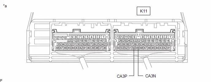
| *a | Component with harness connected (Hybrid Toyota Prius Vehicle Control ECU) | - | - |
Standard Resistance:
 Click Location & Routing(K11) Click Connector(K11)
 | Tester Connection | Condition | Specified Condition |
|---|---|---|
| K11-50 (CA3P) - K11-49 (CA3N) | Cable disconnected from negative (-) auxiliary battery terminal | Below 70 Ω |
| NG |

| GO TO STEP 41 |
|

| 2. | CHECK FOR SHORT IN CAN BUS LINES |
(a) Measure the resistance according to the value(s) in the table below.

| *a | Component with harness connected (Hybrid Toyota Prius Vehicle Control ECU) | - | - |
Standard Resistance:
 Click Location & Routing(K11) Click Connector(K11)
 | Tester Connection | Condition | Specified Condition |
|---|---|---|
| K11-50 (CA3P) - K11-49 (CA3N) | Cable disconnected from negative (-) auxiliary battery terminal | 54 Ω or higher |
| NG |

| GO TO STEP 29 |
|

| 3. | CHECK FOR SHORT TO B IN CAN BUS LINE |
(a) Measure the resistance according to the value(s) in the table below.
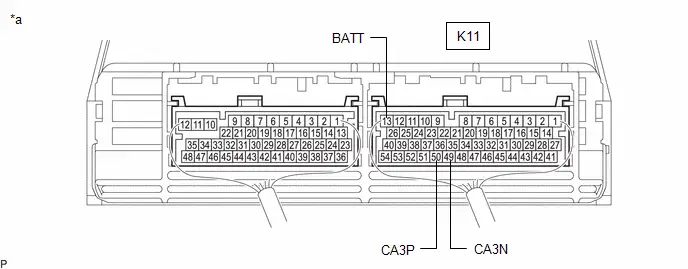
| *a | Component with harness connected (Hybrid Toyota Prius Vehicle Control ECU) | - | - |
Standard Resistance:
 Click Location & Routing(K11) Click Connector(K11)
 | Tester Connection | Condition | Specified Condition |
|---|---|---|
| K11-50 (CA3P) - K11-13 (BATT) | Cable disconnected from negative (-) auxiliary battery terminal | 6 kΩ or higher |
| K11-49 (CA3N) - K11-13 (BATT) |
| NG |

| GO TO STEP 17 |
|

| 4. | CHECK FOR SHORT TO GND IN CAN BUS LINE |
(a) Measure the resistance according to the value(s) in the table below.
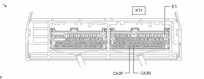
| *a | Component with harness connected (Hybrid Toyota Prius Vehicle Control ECU) | - | - |
Standard Resistance:
 Click Location & Routing(K11) Click Connector(K11)
 | Tester Connection | Condition | Specified Condition |
|---|---|---|
| K11-50 (CA3P) - K11-1 (E1) | Cable disconnected from negative (-) auxiliary battery terminal | 200 Ω or higher |
| K11-49 (CA3N) - K11-1 (E1) |
| OK |

| INSPECT FOR INTERMITTENT PROBLEMS |
|

| 5. | CHECK FOR SHORT TO GND IN CAN BUS LINE (NO. 1 CAN JUNCTION CONNECTOR - HYBRID Toyota Prius Vehicle CONTROL ECU) |
(a) Disconnect the A63 No. 1 CAN junction connector.
(b) Measure the resistance according to the value(s) in the table below.
Standard Resistance:
 Click Location & Routing(A63,K8) Click Connector(A63) Click Connector(K8)
 | Tester Connection | Condition | Specified Condition |
|---|---|---|
| A63-2 (CANH) - K8-4 (CG) | Cable disconnected from negative (-) auxiliary battery terminal | 200 Ω or higher |
| A63-6 (CANL) - K8-4 (CG) |
| NG |

| GO TO STEP 8 |
|

| 6. | CHECK FOR SHORT TO GND IN CAN BUS LINE (NO. 1 CAN JUNCTION CONNECTOR - NO. 2 CAN JUNCTION CONNECTOR) |
(a) Measure the resistance according to the value(s) in the table below.
Standard Resistance:
 Click Location & Routing(A63,K8) Click Connector(A63) Click Connector(K8)
 | Tester Connection | Condition | Specified Condition |
|---|---|---|
| A63-3 (CANH) - K8-4 (CG) | Cable disconnected from negative (-) auxiliary battery terminal | 200 Ω or higher |
| A63-7 (CANL) - K8-4 (CG) |
| NG |

| GO TO STEP 10 |
|

| 7. | CHECK FOR SHORT TO GND IN CAN BUS LINE (NO. 1 CAN JUNCTION CONNECTOR - NO. 1 SKID CONTROL ECU (BRAKE BOOSTER WITH MASTER CYLINDER ASSEMBLY)) |
(a) Measure the resistance according to the value(s) in the table below.
Standard Resistance:
 Click Location & Routing(A63,K8) Click Connector(A63) Click Connector(K8)
 | Tester Connection | Condition | Specified Condition |
|---|---|---|
| A63-1 (CANH) - K8-4 (CG) | Cable disconnected from negative (-) auxiliary battery terminal | 200 Ω or higher |
| A63-5 (CANL) - K8-4 (CG) |
| OK |

| REPLACE NO. 1 CAN JUNCTION CONNECTOR |
| NG |

| GO TO STEP 9 |
| 8. | CHECK FOR SHORT TO GND IN CAN BUS LINE (NO. 1 CAN JUNCTION CONNECTOR - HYBRID Toyota Prius Vehicle CONTROL ECU) |
(a) Disconnect the K11 hybrid vehicle control ECU connector.
(b) Measure the resistance according to the value(s) in the table below.
Standard Resistance:
 Click Location & Routing(A63,K8) Click Connector(A63) Click Connector(K8)
 | Tester Connection | Condition | Specified Condition |
|---|---|---|
| A63-2 (CANH) - K8-4 (CG) | Cable disconnected from negative (-) auxiliary battery terminal | 200 Ω or higher |
| A63-6 (CANL) - K8-4 (CG) |
| OK |

| REPLACE HYBRID Toyota Prius Vehicle CONTROL ECU
|


| NG |

| REPAIR OR REPLACE CAN MAIN BUS LINE OR CONNECTOR (NO. 1 CAN JUNCTION CONNECTOR - HYBRID Toyota Prius Vehicle CONTROL ECU) |
| 9. | CHECK FOR SHORT TO GND IN CAN BUS LINE (NO. 1 CAN JUNCTION CONNECTOR - NO. 1 SKID CONTROL ECU (BRAKE BOOSTER WITH MASTER CYLINDER ASSEMBLY)) |
(a) Disconnect the A3 No. 1 skid control ECU (brake booster with master cylinder assembly) connector.
(b) Measure the resistance according to the value(s) in the table below.
Standard Resistance:
 Click Location & Routing(A63,K8) Click Connector(A63) Click Connector(K8)
 | Tester Connection | Condition | Specified Condition |
|---|---|---|
| A63-1 (CANH) - K8-4 (CG) | Cable disconnected from negative (-) auxiliary battery terminal | 200 Ω or higher |
| A63-5 (CANL) - K8-4 (CG) |
| OK |

| REPLACE NO. 1 SKID CONTROL ECU (BRAKE BOOSTER WITH MASTER CYLINDER ASSEMBLY)
|


| NG |

| REPAIR OR REPLACE CAN BRANCH LINE OR CONNECTOR (NO. 1 CAN JUNCTION CONNECTOR - NO. 1 SKID CONTROL ECU (BRAKE BOOSTER WITH MASTER CYLINDER ASSEMBLY)) |
| 10. | CHECK FOR SHORT TO GND IN CAN BUS LINE (NO. 2 CAN JUNCTION CONNECTOR - NO. 1 CAN JUNCTION CONNECTOR) |
(a) Disconnect the A64 No. 2 CAN junction connector.
(b) Measure the resistance according to the value(s) in the table below.
Standard Resistance:
 Click Location & Routing(A64,K8) Click Connector(A64) Click Connector(K8)
 | Tester Connection | Condition | Specified Condition |
|---|---|---|
| A64-4 (CANH) - K8-4 (CG) | Cable disconnected from negative (-) auxiliary battery terminal | 200 Ω or higher |
| A64-8 (CANL) - K8-4 (CG) |
| NG |

| REPAIR OR REPLACE CAN MAIN BUS LINE OR CONNECTOR (NO. 2 CAN JUNCTION CONNECTOR - NO. 1 CAN JUNCTION CONNECTOR) |
|

| 11. | CHECK FOR SHORT TO GND IN CAN BUS LINE (NO. 2 CAN JUNCTION CONNECTOR - NO. 2 SKID CONTROL ECU (BRAKE ACTUATOR ASSEMBLY)) |
(a) Measure the resistance according to the value(s) in the table below.
Standard Resistance:
 Click Location & Routing(A64,K8) Click Connector(A64) Click Connector(K8)
 | Tester Connection | Condition | Specified Condition |
|---|---|---|
| A64-2 (CANH) - K8-4 (CG) | Cable disconnected from negative (-) auxiliary battery terminal | 200 Ω or higher |
| A64-6 (CANL) - K8-4 (CG) |
| NG |

| GO TO STEP 14 |
|

| 12. | CHECK FOR SHORT TO GND IN CAN BUS LINE (NO. 2 CAN JUNCTION CONNECTOR - ECM) |
(a) Measure the resistance according to the value(s) in the table below.
Standard Resistance:
 Click Location & Routing(A64,K8) Click Connector(A64) Click Connector(K8)
 | Tester Connection | Condition | Specified Condition |
|---|---|---|
| A64-3 (CANH) - K8-4 (CG) | Cable disconnected from negative (-) auxiliary battery terminal | 200 Ω or higher |
| A64-7 (CANL) - K8-4 (CG) |
| NG |

| GO TO STEP 15 |
|

| 13. | CHECK FOR SHORT TO GND IN CAN BUS LINE (NO. 2 CAN JUNCTION CONNECTOR - INVERTER WITH CONVERTER ASSEMBLY) |
(a) Measure the resistance according to the value(s) in the table below.
Standard Resistance:
 Click Location & Routing(A64,K8) Click Connector(A64) Click Connector(K8)
 | Tester Connection | Condition | Specified Condition |
|---|---|---|
| A64-1 (CANH) - K8-4 (CG) | Cable disconnected from negative (-) auxiliary battery terminal | 200 Ω or higher |
| A64-5 (CANL) - K8-4 (CG) |
| OK |

| REPLACE NO. 2 CAN JUNCTION CONNECTOR |
| NG |

| GO TO STEP 16 |
| 14. | CHECK FOR SHORT TO GND IN CAN BUS LINE (NO. 2 CAN JUNCTION CONNECTOR - NO. 2 SKID CONTROL ECU (BRAKE ACTUATOR ASSEMBLY)) |
(a) Disconnect the A4 No. 2 skid control ECU (brake actuator assembly) connector.
(b) Measure the resistance according to the value(s) in the table below.
Standard Resistance:
 Click Location & Routing(A64,K8) Click Connector(A64) Click Connector(K8)
 | Tester Connection | Condition | Specified Condition |
|---|---|---|
| A64-2 (CANH) - K8-4 (CG) | Cable disconnected from negative (-) auxiliary battery terminal | 200 Ω or higher |
| A64-6 (CANL) - K8-4 (CG) |
| OK |

| REPLACE NO. 2 SKID CONTROL ECU (BRAKE ACTUATOR ASSEMBLY)
|


| NG |

| REPAIR OR REPLACE CAN MAIN BUS LINE OR CONNECTOR (NO. 2 CAN JUNCTION CONNECTOR - NO. 2 SKID CONTROL ECU (BRAKE ACTUATOR ASSEMBLY)) |
| 15. | CHECK FOR SHORT TO GND IN CAN BUS LINE (NO. 2 CAN JUNCTION CONNECTOR - ECM) |
(a) Disconnect the A91 or A92 ECM connector.
(b) Measure the resistance according to the value(s) in the table below.
Standard Resistance:
 Click Location & Routing(A64,K8) Click Connector(A64) Click Connector(K8)
 | Tester Connection | Condition | Specified Condition |
|---|---|---|
| A64-3 (CANH) - K8-4 (CG) | Cable disconnected from negative (-) auxiliary battery terminal | 200 Ω or higher |
| A64-7 (CANL) - K8-4 (CG) |
| OK |

| REPLACE ECM
|


| NG |

| REPAIR OR REPLACE CAN BRANCH LINE OR CONNECTOR (NO. 2 CAN JUNCTION CONNECTOR - ECM) |
| 16. | CHECK FOR SHORT TO GND IN CAN BUS LINE (NO. 2 CAN JUNCTION CONNECTOR - INVERTER WITH CONVERTER ASSEMBLY) |
(a) Disconnect the A88 inverter with converter assembly connector.
(b) Measure the resistance according to the value(s) in the table below.
Standard Resistance:
 Click Location & Routing(A64,K8) Click Connector(A64) Click Connector(K8)
 | Tester Connection | Condition | Specified Condition |
|---|---|---|
| A64-1 (CANH) - K8-4 (CG) | Cable disconnected from negative (-) auxiliary battery terminal | 200 Ω or higher |
| A64-5 (CANL) - K8-4 (CG) |
| OK |

| REPLACE INVERTER WITH CONVERTER ASSEMBLY |
| NG |

| REPAIR OR REPLACE CAN BRANCH LINE OR CONNECTOR (NO. 2 CAN JUNCTION CONNECTOR - INVERTER WITH CONVERTER ASSEMBLY) |
| 17. | CHECK FOR SHORT TO B IN CAN BUS LINE (NO. 1 CAN JUNCTION CONNECTOR - HYBRID Toyota Prius Vehicle CONTROL ECU) |
(a) Disconnect the A63 No. 1 CAN junction connector.
(b) Measure the resistance according to the value(s) in the table below.
Standard Resistance:
 Click Location & Routing(A63,K8) Click Connector(A63) Click Connector(K8)
 | Tester Connection | Condition | Specified Condition |
|---|---|---|
| A63-2 (CANH) - K8-16 (BAT) | Cable disconnected from negative (-) auxiliary battery terminal | 6 kΩ or higher |
| A63-6 (CANL) - K8-16 (BAT) |
| NG |

| GO TO STEP 20 |
|

| 18. | CHECK FOR SHORT TO B IN CAN BUS LINE (NO. 1 CAN JUNCTION CONNECTOR - NO. 2 CAN JUNCTION CONNECTOR) |
(a) Measure the resistance according to the value(s) in the table below.
Standard Resistance:
 Click Location & Routing(A63,K8) Click Connector(A63) Click Connector(K8)
 | Tester Connection | Condition | Specified Condition |
|---|---|---|
| A63-3 (CANH) - K8-16 (BAT) | Cable disconnected from negative (-) auxiliary battery terminal | 6 kΩ or higher |
| A63-7 (CANL) - K8-16 (BAT) |
| NG |

| GO TO STEP 22 |
|

| 19. | CHECK FOR SHORT TO B IN CAN BUS LINE (NO. 1 CAN JUNCTION CONNECTOR - NO. 1 SKID CONTROL ECU (BRAKE BOOSTER WITH MASTER CYLINDER ASSEMBLY)) |
(a) Measure the resistance according to the value(s) in the table below.
Standard Resistance:
 Click Location & Routing(A63,K8) Click Connector(A63) Click Connector(K8)
 | Tester Connection | Condition | Specified Condition |
|---|---|---|
| A63-1 (CANH) - K8-16 (BAT) | Cable disconnected from negative (-) auxiliary battery terminal | 6 kΩ or higher |
| A63-5 (CANL) - K8-16 (BAT) |
| OK |

| REPLACE NO. 1 CAN JUNCTION CONNECTOR |
| NG |

| GO TO STEP 21 |
| 20. | CHECK FOR SHORT TO B IN CAN BUS LINE (NO. 1 CAN JUNCTION CONNECTOR - HYBRID Toyota Prius Vehicle CONTROL ECU) |
(a) Disconnect the K11 hybrid vehicle control ECU connector.
(b) Measure the resistance according to the value(s) in the table below.
Standard Resistance:
 Click Location & Routing(A63,K8) Click Connector(A63) Click Connector(K8)
 | Tester Connection | Condition | Specified Condition |
|---|---|---|
| A63-2 (CANH) - K8-16 (BAT) | Cable disconnected from negative (-) auxiliary battery terminal | 6 kΩ or higher |
| A63-6 (CANL) - K8-16 (BAT) |
| OK |

| REPLACE HYBRID Toyota Prius Vehicle CONTROL ECU
|


| NG |

| REPAIR OR REPLACE CAN MAIN BUS LINE OR CONNECTOR (NO. 1 CAN JUNCTION CONNECTOR - HYBRID Toyota Prius Vehicle CONTROL ECU) |
| 21. | CHECK FOR SHORT TO B IN CAN BUS LINE (NO. 1 CAN JUNCTION CONNECTOR - NO. 1 SKID CONTROL ECU (BRAKE BOOSTER WITH MASTER CYLINDER ASSEMBLY)) |
(a) Disconnect the A3 No. 1 skid control ECU (brake booster with master cylinder assembly) connector.
(b) Measure the resistance according to the value(s) in the table below.
Standard Resistance:
 Click Location & Routing(A63,K8) Click Connector(A63) Click Connector(K8)
 | Tester Connection | Condition | Specified Condition |
|---|---|---|
| A63-1 (CANH) - K8-16 (BAT) | Cable disconnected from negative (-) auxiliary battery terminal | 6 kΩ or higher |
| A63-5 (CANL) - K8-16 (BAT) |
| OK |

| REPLACE NO. 1 SKID CONTROL ECU (BRAKE BOOSTER WITH MASTER CYLINDER ASSEMBLY)
|


| NG |

| REPAIR OR REPLACE CAN BRANCH LINE OR CONNECTOR (NO. 1 CAN JUNCTION CONNECTOR - NO. 1 SKID CONTROL ECU (BRAKE BOOSTER WITH MASTER CYLINDER ASSEMBLY)) |
| 22. | CHECK FOR SHORT TO B IN CAN BUS LINE (NO. 2 CAN JUNCTION CONNECTOR - NO. 1 CAN JUNCTION CONNECTOR) |
(a) Disconnect the A64 No. 2 CAN junction connector.
(b) Measure the resistance according to the value(s) in the table below.
Standard Resistance:
 Click Location & Routing(A64,K8) Click Connector(A64) Click Connector(K8)
 | Tester Connection | Condition | Specified Condition |
|---|---|---|
| A64-4 (CANH) - K8-16 (BAT) | Cable disconnected from negative (-) auxiliary battery terminal | 6 kΩ or higher |
| A64-8 (CANL) - K8-16 (BAT) |
| NG |

| REPAIR OR REPLACE CAN MAIN BUS LINE OR CONNECTOR (NO. 2 CAN JUNCTION CONNECTOR - NO. 1 CAN JUNCTION CONNECTOR) |
|

| 23. | CHECK FOR SHORT TO B IN CAN BUS LINE (NO. 2 CAN JUNCTION CONNECTOR - NO. 2 SKID CONTROL ECU (BRAKE ACTUATOR ASSEMBLY)) |
(a) Measure the resistance according to the value(s) in the table below.
Standard Resistance:
 Click Location & Routing(A64,K8) Click Connector(A64) Click Connector(K8)
 | Tester Connection | Condition | Specified Condition |
|---|---|---|
| A64-2 (CANH) - K8-16 (BAT) | Cable disconnected from negative (-) auxiliary battery terminal | 6 kΩ or higher |
| A64-6 (CANL) - K8-16 (BAT) |
| NG |

| GO TO STEP 26 |
|

| 24. | CHECK FOR SHORT TO B IN CAN BUS LINE (NO. 2 CAN JUNCTION CONNECTOR - ECM) |
(a) Measure the resistance according to the value(s) in the table below.
Standard Resistance:
 Click Location & Routing(A64,K8) Click Connector(A64) Click Connector(K8)
 | Tester Connection | Condition | Specified Condition |
|---|---|---|
| A64-3 (CANH) - K8-16 (BAT) | Cable disconnected from negative (-) auxiliary battery terminal | 6 kΩ or higher |
| A64-7 (CANL) - K8-16 (BAT) |
| NG |

| GO TO STEP 27 |
|

| 25. | CHECK FOR SHORT TO B IN CAN BUS LINE (NO. 2 CAN JUNCTION CONNECTOR - INVERTER WITH CONVERTER ASSEMBLY) |
(a) Measure the resistance according to the value(s) in the table below.
Standard Resistance:
 Click Location & Routing(A64,K8) Click Connector(A64) Click Connector(K8)
 | Tester Connection | Condition | Specified Condition |
|---|---|---|
| A64-1 (CANH) - K8-16 (BAT) | Cable disconnected from negative (-) auxiliary battery terminal | 6 kΩ or higher |
| A64-5 (CANL) - K8-16 (BAT) |
| OK |

| REPLACE NO. 2 CAN JUNCTION CONNECTOR |
| NG |

| GO TO STEP 28 |
| 26. | CHECK FOR SHORT TO B IN CAN BUS LINE (NO. 2 CAN JUNCTION CONNECTOR - NO. 2 SKID CONTROL ECU (BRAKE ACTUATOR ASSEMBLY)) |
(a) Disconnect the A4 No. 2 skid control ECU (brake actuator assembly) connector.
(b) Measure the resistance according to the value(s) in the table below.
Standard Resistance:
 Click Location & Routing(A64,K8) Click Connector(A64) Click Connector(K8)
 | Tester Connection | Condition | Specified Condition |
|---|---|---|
| A64-2 (CANH) - K8-16 (BAT) | Cable disconnected from negative (-) auxiliary battery terminal | 6 kΩ or higher |
| A64-6 (CANL) - K8-16 (BAT) |
| OK |

| REPLACE NO. 2 SKID CONTROL ECU (BRAKE ACTUATOR ASSEMBLY)
|


| NG |

| REPAIR OR REPLACE CAN MAIN BUS LINE OR CONNECTOR (NO. 2 CAN JUNCTION CONNECTOR - NO. 2 SKID CONTROL ECU (BRAKE ACTUATOR ASSEMBLY)) |
| 27. | CHECK FOR SHORT TO B IN CAN BUS LINE (NO. 2 CAN JUNCTION CONNECTOR - ECM) |
(a) Disconnect the A91 or A92 ECM connector.
(b) Measure the resistance according to the value(s) in the table below.
Standard Resistance:
 Click Location & Routing(A64,K8) Click Connector(A64) Click Connector(K8)
 | Tester Connection | Condition | Specified Condition |
|---|---|---|
| A64-3 (CANH) - K8-16 (BAT) | Cable disconnected from negative (-) auxiliary battery terminal | 6 kΩ or higher |
| A64-7 (CANL) - K8-16 (BAT) |
| OK |

| REPLACE ECM
|


| NG |

| REPAIR OR REPLACE CAN BRANCH LINE OR CONNECTOR (NO. 2 CAN JUNCTION CONNECTOR - ECM) |
| 28. | CHECK FOR SHORT TO B IN CAN BUS LINE (NO. 2 CAN JUNCTION CONNECTOR - INVERTER WITH CONVERTER ASSEMBLY) |
(a) Disconnect the A88 inverter with converter assembly connector.
(b) Measure the resistance according to the value(s) in the table below.
Standard Resistance:
 Click Location & Routing(A64,K8) Click Connector(A64) Click Connector(K8)
 | Tester Connection | Condition | Specified Condition |
|---|---|---|
| A64-1 (CANH) - K8-16 (BAT) | Cable disconnected from negative (-) auxiliary battery terminal | 6 kΩ or higher |
| A64-5 (CANL) - K8-16 (BAT) |
| OK |

| REPLACE INVERTER WITH CONVERTER ASSEMBLY |
| NG |

| REPAIR OR REPLACE CAN BRANCH LINE OR CONNECTOR (NO. 2 CAN JUNCTION CONNECTOR - INVERTER WITH CONVERTER ASSEMBLY) |
| 29. | CHECK FOR SHORT IN CAN BUS LINES (NO. 1 CAN JUNCTION CONNECTOR - HYBRID Toyota Prius Vehicle CONTROL ECU) |
(a) Disconnect the A63 No. 1 CAN junction connector.
(b) Measure the resistance according to the value(s) in the table below.
Standard Resistance:
 Click Location & Routing(A63) Click Connector(A63)
 | Tester Connection | Condition | Specified Condition |
|---|---|---|
| A63-2 (CANH) - A63-6 (CANL) | Cable disconnected from negative (-) auxiliary battery terminal | 108 to 132 Ω |
| NG |

| GO TO STEP 32 |
|

| 30. | CHECK FOR SHORT IN CAN BUS LINES (NO. 1 CAN JUNCTION CONNECTOR - NO. 2 CAN JUNCTION CONNECTOR) |
(a) Measure the resistance according to the value(s) in the table below.
Standard Resistance:
 Click Location & Routing(A63) Click Connector(A63)
 | Tester Connection | Condition | Specified Condition |
|---|---|---|
| A63-3 (CANH) - A63-7 (CANL) | Cable disconnected from negative (-) auxiliary battery terminal | 108 to 132 Ω |
| NG |

| GO TO STEP 34 |
|

| 31. | CHECK FOR SHORT IN CAN BUS LINES (NO. 1 CAN JUNCTION CONNECTOR - NO. 1 SKID CONTROL ECU (BRAKE BOOSTER WITH MASTER CYLINDER ASSEMBLY)) |
(a) Measure the resistance according to the value(s) in the table below.
Standard Resistance:
 Click Location & Routing(A63) Click Connector(A63)
 | Tester Connection | Condition | Specified Condition |
|---|---|---|
| A63-1 (CANH) - A63-5 (CANL) | Cable disconnected from negative (-) auxiliary battery terminal | 200 Ω or higher |
| OK |

| REPLACE NO. 1 CAN JUNCTION CONNECTOR |
| NG |

| GO TO STEP 33 |
| 32. | CHECK FOR SHORT IN CAN BUS LINES (NO. 1 CAN JUNCTION CONNECTOR - HYBRID Toyota Prius Vehicle CONTROL ECU) |
(a) Disconnect the K11 hybrid vehicle control ECU connector.
(b) Measure the resistance according to the value(s) in the table below.
Standard Resistance:
 Click Location & Routing(A63) Click Connector(A63)
 | Tester Connection | Condition | Specified Condition |
|---|---|---|
| A63-2 (CANH) - A63-6 (CANL) | Cable disconnected from negative (-) auxiliary battery terminal | 1 MΩ or higher |
| OK |

| REPLACE HYBRID Toyota Prius Vehicle CONTROL ECU
|


| NG |

| REPAIR OR REPLACE CAN MAIN BUS LINES OR CONNECTOR (NO. 1 CAN JUNCTION CONNECTOR - HYBRID Toyota Prius Vehicle CONTROL ECU) |
| 33. | CHECK FOR SHORT IN CAN BUS LINES (NO. 1 CAN JUNCTION CONNECTOR - NO. 1 SKID CONTROL ECU (BRAKE BOOSTER WITH MASTER CYLINDER ASSEMBLY)) |
(a) Disconnect the A3 No. 1 skid control ECU (brake booster with master cylinder assembly) connector.
(b) Measure the resistance according to the value(s) in the table below.
Standard Resistance:
 Click Location & Routing(A63) Click Connector(A63)
 | Tester Connection | Condition | Specified Condition |
|---|---|---|
| A63-1 (CANH) - A63-5 (CANL) | Cable disconnected from negative (-) auxiliary battery terminal | 1 MΩ or higher |
| OK |

| REPLACE NO. 1 SKID CONTROL ECU (BRAKE BOOSTER WITH MASTER CYLINDER ASSEMBLY)
|


| NG |

| REPAIR OR REPLACE CAN BRANCH LINES OR CONNECTOR (NO. 1 CAN JUNCTION CONNECTOR - NO. 1 SKID CONTROL ECU (BRAKE BOOSTER WITH MASTER CYLINDER ASSEMBLY)) |
| 34. | CHECK FOR SHORT IN CAN BUS LINES (NO. 2 CAN JUNCTION CONNECTOR - NO. 1 CAN JUNCTION CONNECTOR) |
(a) Reconnect the A63 No. 1 CAN junction connector.
(b) Disconnect the A64 No. 2 CAN junction connector.
(c) Measure the resistance according to the value(s) in the table below.
Standard Resistance:
 Click Location & Routing(A64) Click Connector(A64)
 | Tester Connection | Condition | Specified Condition |
|---|---|---|
| A64-4 (CANH) - A64-8 (CANL) | Cable disconnected from negative (-) auxiliary battery terminal | 108 to 132 Ω |
| NG |

| REPAIR OR REPLACE CAN MAIN BUS LINES OR CONNECTOR (NO. 2 CAN JUNCTION CONNECTOR - NO. 1 CAN JUNCTION CONNECTOR) |
|

| 35. | CHECK FOR SHORT IN CAN BUS LINES (NO. 2 CAN JUNCTION CONNECTOR - NO. 2 SKID CONTROL ECU (BRAKE ACTUATOR ASSEMBLY)) |
(a) Measure the resistance according to the value(s) in the table below.
Standard Resistance:
 Click Location & Routing(A64) Click Connector(A64)
 | Tester Connection | Condition | Specified Condition |
|---|---|---|
| A64-2 (CANH) - A64-6 (CANL) | Cable disconnected from negative (-) auxiliary battery terminal | 108 to 132 Ω |
| NG |

| GO TO STEP 38 |
|

| 36. | CHECK FOR SHORT IN CAN BUS LINES (NO. 2 CAN JUNCTION CONNECTOR - ECM) |
(a) Measure the resistance according to the value(s) in the table below.
Standard Resistance:
 Click Location & Routing(A64) Click Connector(A64)
 | Tester Connection | Condition | Specified Condition |
|---|---|---|
| A64-3 (CANH) - A64-7 (CANL) | Cable disconnected from negative (-) auxiliary battery terminal | 200 Ω or higher |
| NG |

| GO TO STEP 39 |
|

| 37. | CHECK FOR SHORT IN CAN BUS LINES (NO. 2 CAN JUNCTION CONNECTOR - INVERTER WITH CONVERTER ASSEMBLY) |
(a) Measure the resistance according to the value(s) in the table below.
Standard Resistance:
 Click Location & Routing(A64) Click Connector(A64)
 | Tester Connection | Condition | Specified Condition |
|---|---|---|
| A64-1 (CANH) - A64-5 (CANL) | Cable disconnected from negative (-) auxiliary battery terminal | 200 Ω or higher |
| OK |

| REPLACE NO. 2 CAN JUNCTION CONNECTOR |
| NG |

| GO TO STEP 40 |
| 38. | CHECK FOR SHORT IN CAN BUS LINES (NO. 2 CAN JUNCTION CONNECTOR - NO. 2 SKID CONTROL ECU (BRAKE ACTUATOR ASSEMBLY)) |
(a) Disconnect the A4 No. 2 skid control ECU (brake actuator assembly) connector.
(b) Measure the resistance according to the value(s) in the table below.
Standard Resistance:
 Click Location & Routing(A64) Click Connector(A64)
 | Tester Connection | Condition | Specified Condition |
|---|---|---|
| A64-2 (CANH) - A64-6 (CANL) | Cable disconnected from negative (-) auxiliary battery terminal | 1 MΩ or higher |
| OK |

| REPLACE NO. 2 SKID CONTROL ECU (BRAKE ACTUATOR ASSEMBLY)
|


| NG |

| REPAIR OR REPLACE CAN MAIN BUS LINES OR CONNECTOR (NO. 2 CAN JUNCTION CONNECTOR - NO. 2 SKID CONTROL ECU (BRAKE ACTUATOR ASSEMBLY)) |
| 39. | CHECK FOR SHORT IN CAN BUS LINES (NO. 2 CAN JUNCTION CONNECTOR - ECM) |
(a) Disconnect the A91 or A92 ECM connector.
(b) Measure the resistance according to the value(s) in the table below.
Standard Resistance:
 Click Location & Routing(A64) Click Connector(A64)
 | Tester Connection | Condition | Specified Condition |
|---|---|---|
| A64-3 (CANH) - A64-7 (CANL) | Cable disconnected from negative (-) auxiliary battery terminal | 1 MΩ or higher |
| OK |

| REPLACE ECM
|


| NG |

| REPAIR OR REPLACE CAN BRANCH LINES OR CONNECTOR (NO. 2 CAN JUNCTION CONNECTOR - ECM) |
| 40. | CHECK FOR SHORT IN CAN BUS LINES (NO. 2 CAN JUNCTION CONNECTOR - INVERTER WITH CONVERTER ASSEMBLY) |
(a) Disconnect the A88 inverter with converter assembly connector.
(b) Measure the resistance according to the value(s) in the table below.
Standard Resistance:
 Click Location & Routing(A64) Click Connector(A64)
 | Tester Connection | Condition | Specified Condition |
|---|---|---|
| A64-1 (CANH) - A64-5 (CANL) | Cable disconnected from negative (-) auxiliary battery terminal | 1 MΩ or higher |
| OK |

| REPLACE INVERTER WITH CONVERTER ASSEMBLY |
| NG |

| REPAIR OR REPLACE CAN BRANCH LINES OR CONNECTOR (NO. 2 CAN JUNCTION CONNECTOR - INVERTER WITH CONVERTER ASSEMBLY) |
| 41. | CHECK FOR OPEN IN CAN MAIN BUS LINES (HYBRID Toyota Prius Vehicle CONTROL ECU) |
(a) Disconnect the K11 hybrid vehicle control ECU connector.
(b) Measure the resistance according to the value(s) in the table below.
Standard Resistance:
 Click Location & Routing(K11) Click Connector(K11)
 | Tester Connection | Condition | Specified Condition |
|---|---|---|
| K11-50 (CA3P) - K11-49 (CA3N) | Cable disconnected from negative (-) auxiliary battery terminal | 108 to 132 Ω |
| OK |

| REPLACE HYBRID Toyota Prius Vehicle CONTROL ECU
|


|

| 42. | CHECK FOR OPEN IN CAN MAIN BUS LINES (NO. 1 CAN JUNCTION CONNECTOR - HYBRID Toyota Prius Vehicle CONTROL ECU) |
(a) Reconnect the K11 hybrid vehicle control ECU connector.
(b) Disconnect the A63 No. 1 CAN junction connector.
(c) Measure the resistance according to the value(s) in the table below.
Standard Resistance:
 Click Location & Routing(A63) Click Connector(A63)
 | Tester Connection | Condition | Specified Condition |
|---|---|---|
| A63-2 (CANH) - A63-6 (CANL) | Cable disconnected from negative (-) auxiliary battery terminal | 108 to 132 Ω |
| NG |

| REPAIR OR REPLACE CAN MAIN BUS LINES OR CONNECTOR (NO. 1 CAN JUNCTION CONNECTOR - HYBRID Toyota Prius Vehicle CONTROL ECU) |
|

| 43. | CHECK FOR OPEN IN CAN MAIN BUS LINES (NO. 1 CAN JUNCTION CONNECTOR - NO. 2 CAN JUNCTION CONNECTOR) |
(a) Measure the resistance according to the value(s) in the table below.
Standard Resistance:
 Click Location & Routing(A63) Click Connector(A63)
 | Tester Connection | Condition | Specified Condition |
|---|---|---|
| A63-3 (CANH) - A63-7 (CANL) | Cable disconnected from negative (-) auxiliary battery terminal | 108 to 132 Ω |
| OK |

| REPLACE NO. 1 CAN JUNCTION CONNECTOR |
|

| 44. | CHECK FOR OPEN IN CAN MAIN BUS LINES (NO. 2 CAN JUNCTION CONNECTOR - NO. 1 CAN JUNCTION CONNECTOR) |
(a) Reconnect the A63 No. 1 CAN junction connector.
(b) Disconnect the A64 No. 2 CAN junction connector.
(c) Measure the resistance according to the value(s) in the table below.
Standard Resistance:
 Click Location & Routing(A64) Click Connector(A64)
 | Tester Connection | Condition | Specified Condition |
|---|---|---|
| A64-4 (CANH) - A64-8 (CANL) | Cable disconnected from negative (-) auxiliary battery terminal | 108 to 132 Ω |
| NG |

| REPAIR OR REPLACE CAN MAIN BUS LINES OR CONNECTOR (NO. 2 CAN JUNCTION CONNECTOR - NO. 1 CAN JUNCTION CONNECTOR) |
|

| 45. | CHECK FOR OPEN IN CAN MAIN BUS LINES (NO. 2 CAN JUNCTION CONNECTOR - NO. 2 SKID CONTROL ECU (BRAKE ACTUATOR ASSEMBLY)) |
(a) Measure the resistance according to the value(s) in the table below.
Standard Resistance:
 Click Location & Routing(A64) Click Connector(A64)
 | Tester Connection | Condition | Specified Condition |
|---|---|---|
| A64-2 (CANH) - A64-6 (CANL) | Cable disconnected from negative (-) auxiliary battery terminal | 108 to 132 Ω |
| OK |

| REPLACE NO. 2 CAN JUNCTION CONNECTOR |
|

| 46. | CHECK FOR OPEN IN CAN MAIN BUS LINES (NO. 2 SKID CONTROL ECU (BRAKE ACTUATOR ASSEMBLY)) |
(a) Reconnect the A64 No. 2 CAN junction connector.
(b) Disconnect the A4 No. 2 skid control ECU (brake actuator assembly) connector.
(c) Measure the resistance according to the value(s) in the table below.
Standard Resistance:
 Click Location & Routing(A4) Click Connector(A4)
 | Tester Connection | Condition | Specified Condition |
|---|---|---|
| A4-16 (CA2H) - A4-17 (CA2L) | Cable disconnected from negative (-) auxiliary battery terminal | 108 to 132 Ω |
| OK |

| REPLACE NO. 2 SKID CONTROL ECU (BRAKE ACTUATOR ASSEMBLY)
|


| NG |

| REPAIR OR REPLACE CAN MAIN BUS LINES OR CONNECTOR (NO. 2 SKID CONTROL ECU (BRAKE ACTUATOR ASSEMBLY) - NO. 2 CAN JUNCTION CONNECTOR) |
Check CAN Communication Connection
DESCRIPTION
| Symptom | Trouble Area |
|---|---|
| Check CAN Communication Connection |
|
WIRING DIAGRAM
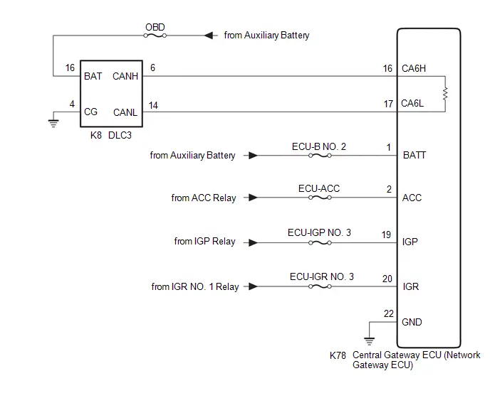
CAUTION / NOTICE / HINT
CAUTION:
When performing the confirmation driving pattern, obey all speed limits and traffic laws.
NOTICE:
-
Because the order of diagnosis is important to allow correct diagnosis, make sure to begin troubleshooting using How to Proceed with Troubleshooting when CAN communication system related DTCs are output.
Click here

- Before measuring the resistance of the CAN bus, turn the ignition switch off and leave the Toyota Prius vehicle for 1 minute or more without operating the key or any switches, or opening or closing the doors. After that, disconnect the cable from the negative (-) auxiliary battery terminal and leave the vehicle for 1 minute or more before measuring the resistance.
-
After the ignition switch is turned off, there may be a waiting time before disconnecting the negative (-) auxiliary battery terminal.
Click here

-
When disconnecting and reconnecting the auxiliary battery.
HINT:
When disconnecting and reconnecting the auxiliary battery, there is an automatic learning function that completes learning when the respective system is used.
Click here


-
Some parts must be initialized and set when replacing or removing and installing parts.
Click here


-
After performing repairs, perform the DTC check procedure and confirm that the DTCs are not output again.
DTC check procedure: Turn the ignition switch to ON and wait for 1 minute or more. Then operate the suspected malfunctioning system and drive the Toyota Prius vehicle at 60 km/h (37 mph) or more for 5 minutes or more.
-
After the repair, perform the CAN bus check and check that all the ECUs and sensors connected to the CAN communication system are displayed as normal.
Click here

- Inspect the fuses for circuits related to this system before performing the following procedure.
HINT:
- Before disconnecting related connectors for inspection, push in on each connector body to check that the connector is not loose or disconnected.
- When a connector is disconnected, check that the terminals and connector body are not cracked, deformed or corroded.
PROCEDURE
| 1. | CHECK GTS OPERATION |
(a) Connect the GTS to the DLC3 of another Toyota Prius vehicle.
(b) Turn the ignition switch to ON.
(c) Turn the GTS on.
(d) Check that the GTS and ECUs can communicate with the ignition switch ON.
HINT:
- ECUs and sensors are not displayed on the "Communication Bus Check" screen when the GTS cannot communicate with the Toyota Prius vehicle.
- If communication between the GTS and ECUs is not possible, either the GTS or vehicle has a malfunction.
- If communication between the GTS and ECUs is still not possible even when the GTS is connected to another vehicle, the GTS has a malfunction. Perform the self tests described in the GTS operator's manual. (The GTS may be malfunctioning or its battery may be discharged.)
| Result | Proceed to |
|---|---|
| OK (Communication between the GTS and the Toyota Prius vehicle is not possible but communication is possible when connected to another vehicle.) | A |
| NG (Communication is not possible between the GTS and the vehicle, nor between the GTS and another vehicle.) | B |
| B |

| REFER TO GTS OPERATOR'S MANUAL |
|

| 2. | CHECK HARNESS AND CONNECTOR (DLC3 POWER SOURCE CIRCUIT) |
(a) Measure the voltage according to the value(s) in the table below.
Standard Voltage:
 Click Location & Routing(K8) Click Connector(K8)
 | Tester Connection | Condition | Specified Condition |
|---|---|---|
| K8-16 (BAT) - Body ground | Ignition switch off | 11 to 14 V |
(b) Disconnect the cable from the negative (-) auxiliary battery terminal.
(c) Measure the resistance according to the value(s) in the table below.
Standard Resistance:
 Click Location & Routing(K8) Click Connector(K8)
 | Tester Connection | Condition | Specified Condition |
|---|---|---|
| K8-4 (CG) - Body ground | Cable disconnected from negative (-) auxiliary battery terminal | Below 1 Ω |
| NG |

| REPAIR OR REPLACE HARNESS OR CONNECTOR (DLC3 POWER SOURCE CIRCUIT) |
|

| 3. | CHECK OPEN IN CAN BUS LINES |
(a) Measure the resistance according to the value(s) in the table below.
Standard Resistance:
 Click Location & Routing(K8) Click Connector(K8)
 | Tester Connection | Condition | Specified Condition |
|---|---|---|
| K8-6 (CANH) - K8-14 (CANL) | Cable disconnected from negative (-) auxiliary battery terminal | Below 70 Ω |
| NG |

| GO TO STEP 7 |
|

| 4. | CHECK SHORT IN CAN BUS LINES |
(a) Measure the resistance according to the value(s) in the table below.
Standard Resistance:
 Click Location & Routing(K8) Click Connector(K8)
 | Tester Connection | Condition | Specified Condition |
|---|---|---|
| K8-6 (CANH) - K8-14 (CANL) | Cable disconnected from negative (-) auxiliary battery terminal | 54 Ω or higher |
| K8-6 (CANH) - K8-4 (CG) | Cable disconnected from negative (-) auxiliary battery terminal | 200 Ω or higher |
| K8-14 (CANL) - K8-4 (CG) | ||
| K8-6 (CANH) - K8-16 (BAT) | Cable disconnected from negative (-) auxiliary battery terminal | 6 kΩ or higher |
| K8-14 (CANL) - K8-16 (BAT) |
| NG |

| GO TO STEP 6 |
|

| 5. | CHECK HARNESS AND CONNECTOR (POWER SOURCE CIRCUIT) |
(a) Disconnect the K78 central gateway ECU (network gateway ECU) connector.
(b) Measure the resistance according to the value(s) in the table below.
Standard Resistance:
 Click Location & Routing(K78) Click Connector(K78)
 | Tester Connection | Condition | Specified Condition |
|---|---|---|
| K78-22 (GND) - Body ground | Cable disconnected from negative (-) auxiliary battery terminal | Below 1 Ω |
(c) Reconnect the cable to the negative (-) auxiliary battery terminal.
(d) Measure the voltage according to the value(s) in the table below.
Standard Voltage:
 Click Location & Routing(K78) Click Connector(K78)
 | Tester Connection | Condition | Specified Condition |
|---|---|---|
| K78-1 (BATT) - Body ground | Ignition switch off | 11 to 14 V |
| K78-2 (ACC) - Body ground | Ignition switch ACC | 11 to 14 V |
| K78-19 (IGP) - Body ground | Ignition switch ON | 11 to 14 V |
| K78-20 (IGR) - Body ground | Ignition switch ON | 11 to 14 V |
| OK |

| REPLACE CENTRAL GATEWAY ECU (NETWORK GATEWAY ECU) |
| NG |

| REPAIR OR REPLACE HARNESS OR CONNECTOR (POWER SOURCE CIRCUIT) |
| 6. | CHECK SHORT IN CAN BUS LINES |
(a) Disconnect the K78 central gateway ECU (network gateway ECU) connector.
(b) Measure the resistance according to the value(s) in the table below.
Standard Resistance:
 Click Location & Routing(K78,K8) Click Connector(K78) Click Connector(K8)
 | Tester Connection | Condition | Specified Condition |
|---|---|---|
| K78-16 (CA6H) - K78-17 (CA6L) | Cable disconnected from negative (-) auxiliary battery terminal | 1 MΩ or higher |
| K78-16 (CA6H) - K8-4 (CG) | Cable disconnected from negative (-) auxiliary battery terminal | 200 Ω or higher |
| K78-17 (CA6L) - K8-4 (CG) | ||
| K78-16 (CA6H) - K8-16 (BAT) | Cable disconnected from negative (-) auxiliary battery terminal | 6 kΩ or higher |
| K78-17 (CA6L) - K8-16 (BAT) |
| OK |

| REPLACE CENTRAL GATEWAY ECU (NETWORK GATEWAY ECU) |
| NG |

| REPAIR OR REPLACE HARNESS OR CONNECTOR (DLC3 - CENTRAL GATEWAY ECU (NETWORK GATEWAY ECU)) |
| 7. | CHECK FOR OPEN IN CAN BUS LINES (CENTRAL GATEWAY ECU (NETWORK GATEWAY ECU) - DLC3) |
(a) Disconnect the K78 central gateway ECU (network gateway ECU) connector.
(b) Measure the resistance according to the value(s) in the table below.
Standard Resistance:
 Click Location & Routing(K78,K8) Click Connector(K78) Click Connector(K8)
 | Tester Connection | Condition | Specified Condition |
|---|---|---|
| K78-16 (CA6H) - K8-6 (CANH) | Cable disconnected from negative (-) auxiliary battery terminal | Below 1 Ω |
| K78-17 (CA6L) - K8-14 (CANL) |
| OK |

| REPLACE CENTRAL GATEWAY ECU (NETWORK GATEWAY ECU) |
| NG |

| REPAIR OR REPLACE HARNESS OR CONNECTOR (CENTRAL GATEWAY ECU (NETWORK GATEWAY ECU) - DLC3) |
Hybrid Vehicle Control ECU Communication Stop Mode
DESCRIPTION
| Detection Item | Symptom | Trouble Area |
|---|---|---|
| Hybrid Toyota Prius Vehicle Control ECU Communication Stop Mode | Communication stop for "Hybrid Vehicle Control" is indicated on the "Communication Bus Check" screen of the GTS. Click here
|
|

WIRING DIAGRAM
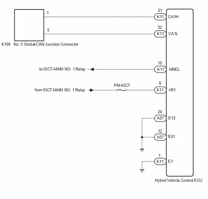
CAUTION / NOTICE / HINT
CAUTION:
When performing the confirmation driving pattern, obey all speed limits and traffic laws.
NOTICE:
-
Because the order of diagnosis is important to allow correct diagnosis, make sure to begin troubleshooting using How to Proceed with Troubleshooting when CAN communication system related DTCs are output.
Click here

- Before measuring the resistance of the CAN bus, turn the ignition switch off and leave the Toyota Prius vehicle for 1 minute or more without operating the key or any switches, or opening or closing the doors. After that, disconnect the cable from the negative (-) auxiliary battery terminal and leave the vehicle for 1 minute or more before measuring the resistance.
-
After the ignition switch is turned off, there may be a waiting time before disconnecting the negative (-) auxiliary battery terminal.
Click here

-
When disconnecting and reconnecting the auxiliary battery.
HINT:
When disconnecting and reconnecting the auxiliary battery, there is an automatic learning function that completes learning when the respective system is used.
Click here


-
Some parts must be initialized and set when replacing or removing and installing parts.
Click here


-
After performing repairs, perform the DTC check procedure and confirm that the DTCs are not output again.
DTC check procedure: Turn the ignition switch to ON and wait for 1 minute or more. Then operate the suspected malfunctioning system and drive the Toyota Prius vehicle at 60 km/h (37 mph) or more for 5 minutes or more.
-
After the repair, perform the CAN bus check and check that all the ECUs and sensors connected to the CAN communication system are displayed as normal.
Click here

- Inspect the fuses for circuits related to this system before performing the following procedure.
-
Before replacing the hybrid Toyota Prius vehicle control ECU, refer to Registration.
Click here

HINT:
- Before disconnecting related connectors for inspection, push in on each connector body to check that the connector is not loose or disconnected.
- When a connector is disconnected, check that the terminals and connector body are not cracked, deformed or corroded.
PROCEDURE
| 1. | CHECK FOR OPEN IN CAN BUS LINES (HYBRID Toyota Prius Vehicle CONTROL ECU BRANCH LINE) |
(a) Disconnect the cable from the negative (-) auxiliary battery terminal.
(b) Disconnect the K11 hybrid vehicle control ECU connector.
(c) Measure the resistance according to the value(s) in the table below.
Standard Resistance:
 Click Location & Routing(K11) Click Connector(K11)
 | Tester Connection | Condition | Specified Condition |
|---|---|---|
| K11-51 (CA1H) - K11-52 (CA1L) | Cable disconnected from negative (-) auxiliary battery terminal | 54 to 69 Ω |
| NG |

| REPAIR OR REPLACE CAN BRANCH LINES OR CONNECTOR (HYBRID Toyota Prius Vehicle CONTROL ECU) |
|

| 2. | CHECK HYBRID Toyota Prius Vehicle CONTROL ECU POWER SOURCE CIRCUIT |
(a) Check the hybrid vehicle control ECU power source circuit.
-
for M20A-FXS:
Click here

-
for 2ZR-FXE:
Click here

| OK |

| REPLACE HYBRID Toyota Prius Vehicle CONTROL ECU
|


| NG |

| REPAIR OR REPLACE HARNESS OR CONNECTOR (POWER SOURCE CIRCUIT) |
Brake Booster (Skid Control ECU) Communication Stop Mode
DESCRIPTION
| Detection Item | Symptom | Trouble Area |
|---|---|---|
| Brake Booster (Skid Control ECU) Communication Stop Mode | Communication stop for "Brake Booster" is indicated on the "Communication Bus Check" screen of the GTS. Click here
|
|

WIRING DIAGRAM
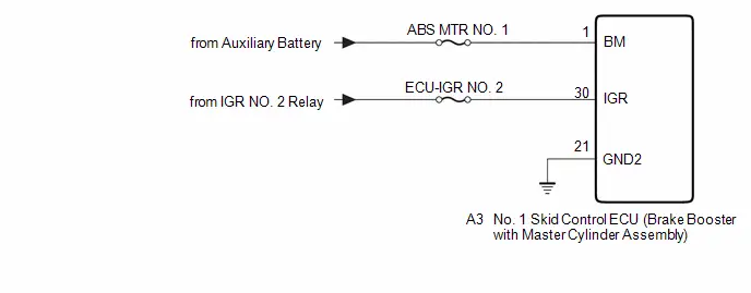
CAUTION / NOTICE / HINT
CAUTION:
When performing the confirmation driving pattern, obey all speed limits and traffic laws.
NOTICE:
-
Because the order of diagnosis is important to allow correct diagnosis, make sure to begin troubleshooting using How to Proceed with Troubleshooting when CAN communication system related DTCs are output.
Click here

- Before measuring the resistance of the CAN bus, turn the ignition switch off and leave the Toyota Prius vehicle for 1 minute or more without operating the key or any switches, or opening or closing the doors. After that, disconnect the cable from the negative (-) auxiliary battery terminal and leave the vehicle for 1 minute or more before measuring the resistance.
-
After the ignition switch is turned off, there may be a waiting time before disconnecting the negative (-) auxiliary battery terminal.
Click here

-
When disconnecting and reconnecting the auxiliary battery.
HINT:
When disconnecting and reconnecting the auxiliary battery, there is an automatic learning function that completes learning when the respective system is used.
Click here


-
Some parts must be initialized and set when replacing or removing and installing parts.
Click here


-
After performing repairs, perform the DTC check procedure and confirm that the DTCs are not output again.
DTC check procedure: Turn the ignition switch to ON and wait for 1 minute or more. Then operate the suspected malfunctioning system and drive the Toyota Prius vehicle at 60 km/h (37 mph) or more for 5 minutes or more.
-
After the repair, perform the CAN bus check and check that all the ECUs and sensors connected to the CAN communication system are displayed as normal.
Click here

- Inspect the fuses for circuits related to this system before performing the following procedure.
- When disconnecting a wire harness of any component connected to the supply power of the integrated capacitor (integration control supply) or when removing the integrated capacitor (integration control supply), make sure to wait 5 minutes or more after turning the ignition switch off for self-diagnosis to complete and the voltage of the integrated capacitor (integration control supply) to discharge.
HINT:
- Before disconnecting related connectors for inspection, push in on each connector body to check that the connector is not loose or disconnected.
- When a connector is disconnected, check that the terminals and connector body are not cracked, deformed or corroded.
PROCEDURE
| 1. | CHECK HARNESS AND CONNECTOR (POWER SOURCE CIRCUIT) |
(a) Disconnect the cable from the negative (-) auxiliary battery terminal.
(b) Disconnect the A3 No. 1 skid control ECU (brake booster with master cylinder assembly) connector.
(c) Measure the resistance according to the value(s) in the table below.
Standard Resistance:
 Click Location & Routing(A3) Click Connector(A3)
 | Tester Connection | Condition | Specified Condition |
|---|---|---|
| A3-21 (GND2) - Body ground | Cable disconnected from negative (-) auxiliary battery terminal | Below 1 Ω |
(d) Reconnect the cable to the negative (-) auxiliary battery terminal.
(e) Measure the voltage according to the value(s) in the table below.
Standard Voltage:
 Click Location & Routing(A3) Click Connector(A3)
 | Tester Connection | Condition | Specified Condition |
|---|---|---|
| A3-1 (BM) - Body ground | Ignition switch off | 11 to 14 V |
| A3-30 (IGR) - Body ground | Ignition switch ON | 11 to 14 V |
| OK |

| REPLACE NO. 1 SKID CONTROL ECU (BRAKE BOOSTER WITH MASTER CYLINDER ASSEMBLY)
|


| NG |

| REPAIR OR REPLACE HARNESS OR CONNECTOR (POWER SOURCE CIRCUIT) |
Clearance Warning ECU Communication Stop Mode
DESCRIPTION
| Detection Item | Symptom | Trouble Area |
|---|---|---|
| Clearance Warning ECU Communication Stop Mode | Communication stop for "Clearance Warning (Intuitive Parking Assist)" is indicated on the "Communication Bus Check" screen of the GTS. Click here
|
|
WIRING DIAGRAM
CAUTION / NOTICE / HINT
CAUTION:
When performing the confirmation driving pattern, obey all speed limits and traffic laws.
NOTICE:
-
Because the order of diagnosis is important to allow correct diagnosis, make sure to begin troubleshooting using How to Proceed with Troubleshooting when CAN communication system related DTCs are output.
Click here

- Before measuring the resistance of the CAN bus, turn the ignition switch off and leave the Toyota Prius vehicle for 1 minute or more without operating the key or any switches, or opening or closing the doors. After that, disconnect the cable from the negative (-) auxiliary battery terminal and leave the vehicle for 1 minute or more before measuring the resistance.
-
After the ignition switch is turned off, there may be a waiting time before disconnecting the negative (-) auxiliary battery terminal.
Click here

-
When disconnecting and reconnecting the auxiliary battery.
HINT:
When disconnecting and reconnecting the auxiliary battery, there is an automatic learning function that completes learning when the respective system is used.
Click here


-
Some parts must be initialized and set when replacing or removing and installing parts.
Click here


-
After performing repairs, perform the DTC check procedure and confirm that the DTCs are not output again.
DTC check procedure: Turn the ignition switch to ON and wait for 1 minute or more. Then operate the suspected malfunctioning system and drive the Toyota Prius vehicle at 60 km/h (37 mph) or more for 5 minutes or more.
-
After the repair, perform the CAN bus check and check that all the ECUs and sensors connected to the CAN communication system are displayed as normal.
Click here

- Inspect the fuses for circuits related to this system before performing the following procedure.
HINT:
- Before disconnecting related connectors for inspection, push in on each connector body to check that the connector is not loose or disconnected.
- When a connector is disconnected, check that the terminals and connector body are not cracked, deformed or corroded.
PROCEDURE
| 1. | CHECK FOR OPEN IN CAN BUS LINES (CLEARANCE WARNING ECU ASSEMBLY BRANCH LINE) |
(a) Disconnect the cable from the negative (-) auxiliary battery terminal.
(b) Disconnect the R36 clearance warning ECU assembly connector.
(c) Measure the resistance according to the value(s) in the table below.
Standard Resistance:
| Tester Connection | Condition | Specified Condition |
|---|---|---|
| R36-17 (R1) - R36-18 (R2) | Cable disconnected from negative (-) auxiliary battery terminal | 54 to 69 Ω |
| NG |
| REPAIR OR REPLACE CAN BRANCH LINES OR CONNECTOR (CLEARANCE WARNING ECU ASSEMBLY) |
|
| 2. | CHECK HARNESS AND CONNECTOR (POWER SOURCE CIRCUIT) |
(a) Measure the resistance according to the value(s) in the table below.
Standard Resistance:
| Tester Connection | Condition | Specified Condition |
|---|---|---|
| R36-31 (E) - Body ground | Cable disconnected from negative (-) auxiliary battery terminal | Below 1 Ω |
(b) Reconnect the cable to the negative (-) auxiliary battery terminal.
(c) Measure the voltage according to the value(s) in the table below.
Standard Voltage:
| Tester Connection | Condition | Specified Condition |
|---|---|---|
| R36-1 (IG) - Body ground | Ignition switch ON | 11 to 14 V |
| OK |
| REPLACE CLEARANCE WARNING ECU ASSEMBLY |
| NG |
| REPAIR OR REPLACE HARNESS OR CONNECTOR (POWER SOURCE CIRCUIT) |
Air Conditioning Amplifier Communication Stop Mode
DESCRIPTION
| Detection Item | Symptom | Trouble Area |
|---|---|---|
| Air Conditioning Amplifier Communication Stop Mode | Communication stop for "Air Conditioning Amplifier" is indicated on the "Communication Bus Check" screen of the GTS. Click here
|
|

WIRING DIAGRAM
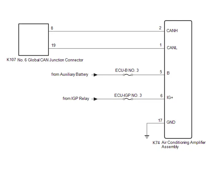
CAUTION / NOTICE / HINT
CAUTION:
When performing the confirmation driving pattern, obey all speed limits and traffic laws.
NOTICE:
-
Because the order of diagnosis is important to allow correct diagnosis, make sure to begin troubleshooting using How to Proceed with Troubleshooting when CAN communication system related DTCs are output.
Click here

- Before measuring the resistance of the CAN bus, turn the ignition switch off and leave the Toyota Prius vehicle for 1 minute or more without operating the key or any switches, or opening or closing the doors. After that, disconnect the cable from the negative (-) auxiliary battery terminal and leave the vehicle for 1 minute or more before measuring the resistance.
-
After the ignition switch is turned off, there may be a waiting time before disconnecting the negative (-) auxiliary battery terminal.
Click here

-
When disconnecting and reconnecting the auxiliary battery.
HINT:
When disconnecting and reconnecting the auxiliary battery, there is an automatic learning function that completes learning when the respective system is used.
Click here


-
Some parts must be initialized and set when replacing or removing and installing parts.
Click here


-
After performing repairs, perform the DTC check procedure and confirm that the DTCs are not output again.
DTC check procedure: Turn the ignition switch to ON and wait for 1 minute or more. Then operate the suspected malfunctioning system and drive the Toyota Prius vehicle at 60 km/h (37 mph) or more for 5 minutes or more.
-
After the repair, perform the CAN bus check and check that all the ECUs and sensors connected to the CAN communication system are displayed as normal.
Click here

- Inspect the fuses for circuits related to this system before performing the following procedure.
HINT:
- Before disconnecting related connectors for inspection, push in on each connector body to check that the connector is not loose or disconnected.
- When a connector is disconnected, check that the terminals and connector body are not cracked, deformed or corroded.
PROCEDURE
| 1. | CHECK FOR OPEN IN CAN BUS LINES (AIR CONDITIONING AMPLIFIER ASSEMBLY BRANCH LINE) |
(a) Disconnect the cable from the negative (-) auxiliary battery terminal.
(b) Disconnect the K74 air conditioning amplifier assembly connector.
(c) Measure the resistance according to the value(s) in the table below.
Standard Resistance:
 Click Location & Routing(K74) Click Connector(K74)
 | Tester Connection | Condition | Specified Condition |
|---|---|---|
| K74-2 (CANH) - K74-1 (CANL) | Cable disconnected from negative (-) auxiliary battery terminal | 54 to 69 Ω |
| NG |

| REPAIR OR REPLACE CAN BRANCH LINES OR CONNECTOR (AIR CONDITIONING AMPLIFIER ASSEMBLY) |
|

| 2. | CHECK HARNESS AND CONNECTOR (POWER SOURCE CIRCUIT) |
(a) Measure the resistance according to the value(s) in the table below.
Standard Resistance:
 Click Location & Routing(K74) Click Connector(K74)
 | Tester Connection | Condition | Specified Condition |
|---|---|---|
| K74-17 (GND) - Body ground | Cable disconnected from negative (-) auxiliary battery terminal | Below 1 Ω |
(b) Reconnect the cable to the negative (-) auxiliary battery terminal.
(c) Measure the voltage according to the value(s) in the table below.
Standard Voltage:
 Click Location & Routing(K74) Click Connector(K74)
 | Tester Connection | Condition | Specified Condition |
|---|---|---|
| K74-5 (B) - Body ground | Ignition switch off | 11 to 14 V |
| K74-6 (IG ) - Body ground | Ignition switch ON | 11 to 14 V |
| OK |

| REPLACE AIR CONDITIONING AMPLIFIER ASSEMBLY |
| NG |

| REPAIR OR REPLACE HARNESS OR CONNECTOR (POWER SOURCE CIRCUIT) |
Power Steering ECU Communication Stop Mode
DESCRIPTION
| Detection Item | Symptom | Trouble Area |
|---|---|---|
| Power Steering ECU Communication Stop Mode | Communication stop for "Power Steering (EPS)" is indicated on the "Communication Bus Check" screen of the GTS. Click here
|
|

WIRING DIAGRAM
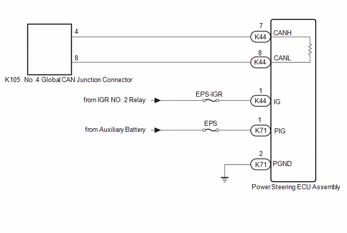
CAUTION / NOTICE / HINT
CAUTION:
When performing the confirmation driving pattern, obey all speed limits and traffic laws.
NOTICE:
-
Because the order of diagnosis is important to allow correct diagnosis, make sure to begin troubleshooting using How to Proceed with Troubleshooting when CAN communication system related DTCs are output.
Click here

- Before measuring the resistance of the CAN bus, turn the ignition switch off and leave the Toyota Prius vehicle for 1 minute or more without operating the key or any switches, or opening or closing the doors. After that, disconnect the cable from the negative (-) auxiliary battery terminal and leave the vehicle for 1 minute or more before measuring the resistance.
-
After the ignition switch is turned off, there may be a waiting time before disconnecting the negative (-) auxiliary battery terminal.
Click here

-
When disconnecting and reconnecting the auxiliary battery.
HINT:
When disconnecting and reconnecting the auxiliary battery, there is an automatic learning function that completes learning when the respective system is used.
Click here


-
Some parts must be initialized and set when replacing or removing and installing parts.
Click here


-
After performing repairs, perform the DTC check procedure and confirm that the DTCs are not output again.
DTC check procedure: Turn the ignition switch to ON and wait for 1 minute or more. Then operate the suspected malfunctioning system and drive the Toyota Prius vehicle at 60 km/h (37 mph) or more for 5 minutes or more.
-
After the repair, perform the CAN bus check and check that all the ECUs and sensors connected to the CAN communication system are displayed as normal.
Click here

- Inspect the fuses for circuits related to this system before performing the following procedure.
HINT:
- Before disconnecting related connectors for inspection, push in on each connector body to check that the connector is not loose or disconnected.
- When a connector is disconnected, check that the terminals and connector body are not cracked, deformed or corroded.
PROCEDURE
| 1. | CHECK FOR OPEN IN CAN BUS LINES (POWER STEERING ECU ASSEMBLY MAIN LINE) |
(a) Disconnect the cable from the negative (-) auxiliary battery terminal.
(b) Disconnect the K44 power steering ECU assembly connector.
(c) Measure the resistance according to the value(s) in the table below.
Standard Resistance:
 Click Location & Routing(K44) Click Connector(K44)
 | Tester Connection | Condition | Specified Condition |
|---|---|---|
| K44-7 (CANH) - K44-8 (CANL) | Cable disconnected from negative (-) auxiliary battery terminal | 108 to 132 Ω |
| NG |

| REPAIR OR REPLACE CAN MAIN BUS LINES OR CONNECTOR (POWER STEERING ECU ASSEMBLY) |
|

| 2. | CHECK HARNESS AND CONNECTOR (POWER SOURCE CIRCUIT) |
(a) Disconnect the K71 power steering ECU assembly connector.
(b) Measure the resistance according to the value(s) in the table below.
Standard Resistance:
 Click Location & Routing(K71) Click Connector(K71)
 | Tester Connection | Condition | Specified Condition |
|---|---|---|
| K71-2 (PGND) - Body ground | Cable disconnected from negative (-) auxiliary battery terminal | Below 1 Ω |
(c) Reconnect the cable to the negative (-) auxiliary battery terminal.
(d) Measure the voltage according to the value(s) in the table below.
Standard Voltage:
 Click Location & Routing(K44,K71) Click Connector(K44) Click Connector(K71)
 | Tester Connection | Condition | Specified Condition |
|---|---|---|
| K44-1 (IG) - Body ground | Ignition switch ON | 8 to 16 V |
| K71-1 (PIG) - Body ground | Ignition switch off | 9 to 16 V |
| OK |

| REPLACE POWER STEERING ECU ASSEMBLY
|


| NG |

| REPAIR OR REPLACE HARNESS OR CONNECTOR (POWER SOURCE CIRCUIT) |
Steering Angle Sensor Communication Stop Mode
DESCRIPTION
| Detection Item | Symptom | Trouble Area |
|---|---|---|
| Steering Angle Sensor Communication Stop Mode | Communication stop for "Spiral cable (Steering Angle Sensor)" is indicated on the "Communication Bus Check" screen of the GTS. Click here
|
|

WIRING DIAGRAM
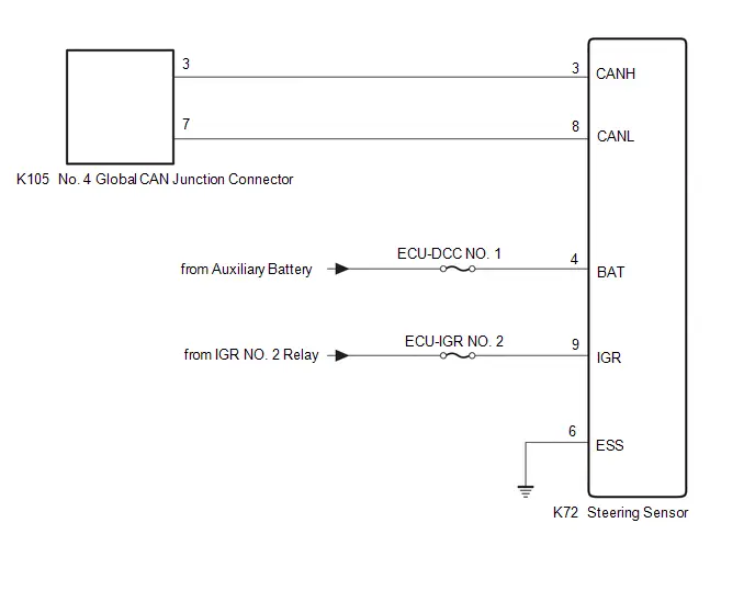
CAUTION / NOTICE / HINT
CAUTION:
When performing the confirmation driving pattern, obey all speed limits and traffic laws.
NOTICE:
-
Because the order of diagnosis is important to allow correct diagnosis, make sure to begin troubleshooting using How to Proceed with Troubleshooting when CAN communication system related DTCs are output.
Click here

- Before measuring the resistance of the CAN bus, turn the ignition switch off and leave the Toyota Prius vehicle for 1 minute or more without operating the key or any switches, or opening or closing the doors. After that, disconnect the cable from the negative (-) auxiliary battery terminal and leave the vehicle for 1 minute or more before measuring the resistance.
-
After the ignition switch is turned off, there may be a waiting time before disconnecting the negative (-) auxiliary battery terminal.
Click here

-
When disconnecting and reconnecting the auxiliary battery.
HINT:
When disconnecting and reconnecting the auxiliary battery, there is an automatic learning function that completes learning when the respective system is used.
Click here


-
Some parts must be initialized and set when replacing or removing and installing parts.
Click here


-
After performing repairs, perform the DTC check procedure and confirm that the DTCs are not output again.
DTC check procedure: Turn the ignition switch to ON and wait for 1 minute or more. Then operate the suspected malfunctioning system and drive the Toyota Prius vehicle at 60 km/h (37 mph) or more for 5 minutes or more.
-
After the repair, perform the CAN bus check and check that all the ECUs and sensors connected to the CAN communication system are displayed as normal.
Click here

- Inspect the fuses for circuits related to this system before performing the following procedure.
HINT:
- Before disconnecting related connectors for inspection, push in on each connector body to check that the connector is not loose or disconnected.
- When a connector is disconnected, check that the terminals and connector body are not cracked, deformed or corroded.
PROCEDURE
| 1. | CHECK FOR OPEN IN CAN BUS LINES (STEERING SENSOR BRANCH LINE) |
(a) Disconnect the cable from the negative (-) auxiliary battery terminal.
(b) Disconnect the K72 steering sensor connector.
(c) Measure the resistance according to the value(s) in the table below.
Standard Resistance:
 Click Location & Routing(K72) Click Connector(K72)
 | Tester Connection | Condition | Specified Condition |
|---|---|---|
| K72-3 (CANH) - K72-8 (CANL) | Cable disconnected from negative (-) auxiliary battery terminal | 54 to 69 Ω |
| NG |

| REPAIR OR REPLACE CAN BRANCH LINES OR CONNECTOR (STEERING SENSOR) |
|

| 2. | CHECK HARNESS AND CONNECTOR (POWER SOURCE CIRCUIT) |
(a) Measure the resistance according to the value(s) in the table below.
Standard Resistance:
 Click Location & Routing(K72) Click Connector(K72)
 | Tester Connection | Condition | Specified Condition |
|---|---|---|
| K72-6 (ESS) - Body ground | Cable disconnected from negative (-) auxiliary battery terminal | Below 1 Ω |
(b) Reconnect the cable to the negative (-) auxiliary battery terminal.
(c) Measure the voltage according to the value(s) in the table below.
Standard Voltage:
 Click Location & Routing(K72) Click Connector(K72)
 | Tester Connection | Condition | Specified Condition |
|---|---|---|
| K72-4 (BAT) - Body ground | Ignition switch off | 11 to 14 V |
| K72-9 (IGR) - Body ground | Ignition switch ON | 11 to 14 V |
| OK |

| REPLACE STEERING SENSOR
|


| NG |

| REPAIR OR REPLACE HARNESS OR CONNECTOR (POWER SOURCE CIRCUIT) |
Shift Control ECU Communication Stop Mode
DESCRIPTION
| Detection Item | Symptom | Trouble Area |
|---|---|---|
| Shift Control ECU Communication Stop Mode | Communication stop for "Transmission Control" is indicated on the "Communication Bus Check" screen of the GTS. Click here
|
|

WIRING DIAGRAM
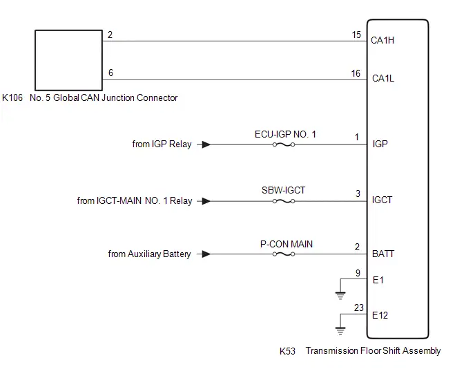
CAUTION / NOTICE / HINT
CAUTION:
When performing the confirmation driving pattern, obey all speed limits and traffic laws.
NOTICE:
-
Because the order of diagnosis is important to allow correct diagnosis, make sure to begin troubleshooting using How to Proceed with Troubleshooting when CAN communication system related DTCs are output.
Click here

- Before measuring the resistance of the CAN bus, turn the ignition switch off and leave the Toyota Prius vehicle for 1 minute or more without operating the key or any switches, or opening or closing the doors. After that, disconnect the cable from the negative (-) auxiliary battery terminal and leave the vehicle for 1 minute or more before measuring the resistance.
-
After the ignition switch is turned off, there may be a waiting time before disconnecting the negative (-) auxiliary battery terminal.
Click here

-
When disconnecting and reconnecting the auxiliary battery.
HINT:
When disconnecting and reconnecting the auxiliary battery, there is an automatic learning function that completes learning when the respective system is used.
Click here


-
Some parts must be initialized and set when replacing or removing and installing parts.
Click here


-
After performing repairs, perform the DTC check procedure and confirm that the DTCs are not output again.
DTC check procedure: Turn the ignition switch to ON and wait for 1 minute or more. Then operate the suspected malfunctioning system and drive the Toyota Prius vehicle at 60 km/h (37 mph) or more for 5 minutes or more.
-
After the repair, perform the CAN bus check and check that all the ECUs and sensors connected to the CAN communication system are displayed as normal.
Click here

- Inspect the fuses for circuits related to this system before performing the following procedure.
- When disconnecting a wire harness of any component connected to the supply power of the integrated capacitor (integration control supply) or when removing the integrated capacitor (integration control supply), make sure to wait 5 minutes or more after turning the ignition switch off for self-diagnosis to complete and the voltage of the integrated capacitor (integration control supply) to discharge.
HINT:
- Before disconnecting related connectors for inspection, push in on each connector body to check that the connector is not loose or disconnected.
- When a connector is disconnected, check that the terminals and connector body are not cracked, deformed or corroded.
PROCEDURE
| 1. | CHECK FOR OPEN IN CAN BUS LINES (TRANSMISSION FLOOR SHIFT ASSEMBLY BRANCH LINE) |
(a) Disconnect the cable from the negative (-) auxiliary battery terminal.
(b) Disconnect the K53 transmission floor shift assembly connector.
(c) Measure the resistance according to the value(s) in the table below.
Standard Resistance:
 Click Location & Routing(K53) Click Connector(K53)
 | Tester Connection | Condition | Specified Condition |
|---|---|---|
| K53-15 (CA1H) - K53-16 (CA1L) | Cable disconnected from negative (-) auxiliary battery terminal | 54 to 69 Ω |
| NG |

| REPAIR OR REPLACE CAN BRANCH LINES OR CONNECTOR (TRANSMISSION FLOOR SHIFT ASSEMBLY) |
|

| 2. | CHECK HARNESS AND CONNECTOR (POWER SOURCE CIRCUIT) |
(a) Measure the resistance according to the value(s) in the table below.
Standard Resistance:
 Click Location & Routing(K53) Click Connector(K53)
 | Tester Connection | Condition | Specified Condition |
|---|---|---|
| K53-23 (E12) - Body ground | Cable disconnected from negative (-) auxiliary battery terminal | Below 1 Ω |
| K53-9 (E1) - Body ground | Cable disconnected from negative (-) auxiliary battery terminal | Below 1 Ω |
(b) Reconnect the cable to the negative (-) auxiliary battery terminal.
(c) Measure the voltage according to the value(s) in the table below.
Standard Voltage:
 Click Location & Routing(K53) Click Connector(K53)
 | Tester Connection | Condition | Specified Condition |
|---|---|---|
| K53-1 (IGP) - Body ground | Ignition switch ON | 11 to 14 V |
| K53-2 (BATT) - Body ground | Ignition switch off | 11 to 14 V |
| K53-3 (IGCT) - Body ground | Ignition switch ON | 11 to 14 V |
| OK |

| REPLACE TRANSMISSION FLOOR SHIFT ASSEMBLY |
| NG |

| REPAIR OR REPLACE HARNESS OR CONNECTOR (POWER SOURCE CIRCUIT) |
Battery ECU Communication Stop Mode
DESCRIPTION
| Detection Item | Symptom | Trouble Area |
|---|---|---|
| Battery ECU Communication Stop Mode | Communication stop for "HV Battery" is indicated on the "Communication Bus Check" screen of the GTS. Click here
|
|

WIRING DIAGRAM
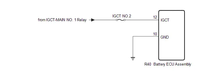
CAUTION / NOTICE / HINT
CAUTION:
When performing the confirmation driving pattern, obey all speed limits and traffic laws.
NOTICE:
-
Because the order of diagnosis is important to allow correct diagnosis, make sure to begin troubleshooting using How to Proceed with Troubleshooting when CAN communication system related DTCs are output.
Click here

- Before measuring the resistance of the CAN bus, turn the ignition switch off and leave the Toyota Prius vehicle for 1 minute or more without operating the key or any switches, or opening or closing the doors. After that, disconnect the cable from the negative (-) auxiliary battery terminal and leave the vehicle for 1 minute or more before measuring the resistance.
-
After the ignition switch is turned off, there may be a waiting time before disconnecting the negative (-) auxiliary battery terminal.
Click here

-
When disconnecting and reconnecting the auxiliary battery.
HINT:
When disconnecting and reconnecting the auxiliary battery, there is an automatic learning function that completes learning when the respective system is used.
Click here


-
Some parts must be initialized and set when replacing or removing and installing parts.
Click here


-
After performing repairs, perform the DTC check procedure and confirm that the DTCs are not output again.
DTC check procedure: Turn the ignition switch to ON and wait for 1 minute or more. Then operate the suspected malfunctioning system and drive the Toyota Prius vehicle at 60 km/h (37 mph) or more for 5 minutes or more.
-
After the repair, perform the CAN bus check and check that all the ECUs and sensors connected to the CAN communication system are displayed as normal.
Click here

- Inspect the fuses for circuits related to this system before performing the following procedure.
HINT:
- Before disconnecting related connectors for inspection, push in on each connector body to check that the connector is not loose or disconnected.
- When a connector is disconnected, check that the terminals and connector body are not cracked, deformed or corroded.
PROCEDURE
| 1. | CHECK BATTERY ECU ASSEMBLY POWER SOURCE CIRCUIT |
(a) Check the battery ECU assembly power source circuit.
-
for M20A-FXS:
Click here

-
for 2ZR-FXE:
Click here

| OK |

| REPLACE BATTERY ECU ASSEMBLY |
| NG |

| REPAIR OR REPLACE HARNESS OR CONNECTOR (POWER SOURCE CIRCUIT) |
Integration Control Supply Communication Stop Mode
DESCRIPTION
| Detection Item | Symptom | Trouble Area |
|---|---|---|
| Integration Control Supply Communication Stop Mode | Communication stop for "Sub Battery System" is indicated on "Communication Bus Check" screen of the GTS. Click here
|
|

WIRING DIAGRAM
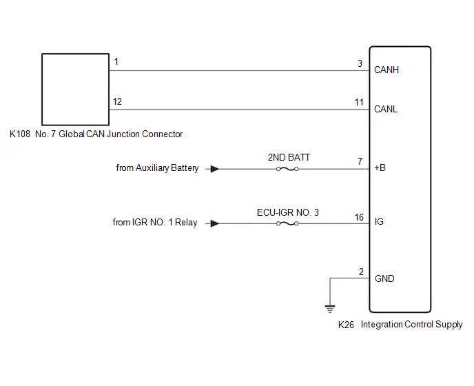
CAUTION / NOTICE / HINT
CAUTION:
When performing the confirmation driving pattern, obey all speed limits and traffic laws.
NOTICE:
-
Because the order of diagnosis is important to allow correct diagnosis, make sure to begin troubleshooting using How to Proceed with Troubleshooting when CAN communication system related DTCs are output.
Click here

- Before measuring the resistance of the CAN bus, turn the ignition switch off and leave the Toyota Prius vehicle for 1 minute or more without operating the key or any switches, or opening or closing the doors. After that, disconnect the cable from the negative (-) auxiliary battery terminal and leave the vehicle for 1 minute or more before measuring the resistance.
-
After the ignition switch is turned off, there may be a waiting time before disconnecting the negative (-) auxiliary battery terminal.
Click here

-
When disconnecting and reconnecting the auxiliary battery.
HINT:
When disconnecting and reconnecting the auxiliary battery, there is an automatic learning function that completes learning when the respective system is used.
Click here


-
Some parts must be initialized and set when replacing or removing and installing parts.
Click here


-
After performing repairs, perform the DTC check procedure and confirm that the DTCs are not output again.
DTC check procedure: Turn the ignition switch to ON and wait for 1 minute or more. Then operate the suspected malfunctioning system and drive the Toyota Prius vehicle at 60 km/h (37 mph) or more for 5 minutes or more.
-
After the repair, perform the CAN bus check and check that all the ECUs and sensors connected to the CAN communication system are displayed as normal.
Click here

- Inspect the fuses for circuits related to this system before performing the following procedure.
- When disconnecting a wire harness of any component connected to the supply power of the integrated capacitor (integration control supply) or when removing the integrated capacitor (integration control supply), make sure to wait 5 minutes or more after turning the ignition switch off for self-diagnosis to complete and the voltage of the integrated capacitor (integration control supply) to discharge.
HINT:
- Before disconnecting related connectors for inspection, push in on each connector body to check that the connector is not loose or disconnected.
- When a connector is disconnected, check that the terminals and connector body are not cracked, deformed or corroded.
PROCEDURE
| 1. | CHECK FOR OPEN IN CAN BUS LINES (INTEGRATION CONTROL SUPPLY BRANCH LINE) |
(a) Disconnect the cable from the negative (-) auxiliary battery terminal.
(b) Disconnect the K26 integration control supply connector.
(c) Measure the resistance according to the value(s) in the table below.
Standard Resistance:
 Click Location & Routing(K26) Click Connector(K26)
 | Tester Connection | Condition | Specified Condition |
|---|---|---|
| K26-3 (CANH) - K26-11 (CANL) | Cable disconnected from negative (-) auxiliary battery terminal | 54 to 69 Ω |
| NG |

| REPAIR OR REPLACE CAN BRANCH LINES OR CONNECTOR (INTEGRATION CONTROL SUPPLY) |
|

| 2. | CHECK HARNESS AND CONNECTOR (POWER SOURCE CIRCUIT) |
(a) Measure the resistance according to the value(s) in the table below.
Standard Resistance:
 Click Location & Routing(K26) Click Connector(K26)
 | Tester Connection | Condition | Specified Condition |
|---|---|---|
| K26-2 (GND) - Body ground | Cable disconnected from negative (-) auxiliary battery terminal | Below 1 Ω |
(b) Reconnect the cable to the negative (-) auxiliary battery terminal.
(c) Measure the voltage according to the value(s) in the table below.
Standard Voltage:
 Click Location & Routing(K26) Click Connector(K26)
 | Tester Connection | Condition | Specified Condition |
|---|---|---|
| K26-16 (IG) - Body ground | Ignition switch ON | 11 to 14 V |
| K26-7 ( B) - Body ground | Ignition switch off | 11 to 14 V |
| OK |

| REPLACE INTEGRATION CONTROL SUPPLY
|


| NG |

| REPAIR OR REPLACE HARNESS OR CONNECTOR (POWER SOURCE CIRCUIT) |
Main Body ECU Communication Stop Mode
DESCRIPTION
| Detection Item | Symptom | Trouble Area |
|---|---|---|
| Main Body ECU Communication Stop Mode | Communication stop for "Main Body" is indicated on the "Communication Bus Check" screen of the GTS. Click here
|
|

WIRING DIAGRAM
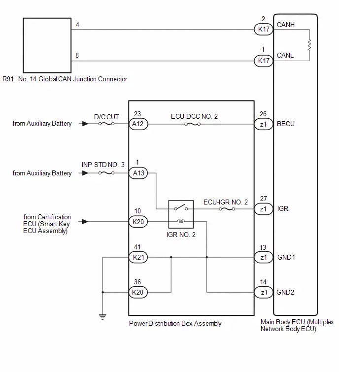
CAUTION / NOTICE / HINT
CAUTION:
When performing the confirmation driving pattern, obey all speed limits and traffic laws.
NOTICE:
-
Because the order of diagnosis is important to allow correct diagnosis, make sure to begin troubleshooting using How to Proceed with Troubleshooting when CAN communication system related DTCs are output.
Click here

- Before measuring the resistance of the CAN bus, turn the ignition switch off and leave the Toyota Prius vehicle for 1 minute or more without operating the key or any switches, or opening or closing the doors. After that, disconnect the cable from the negative (-) auxiliary battery terminal and leave the vehicle for 1 minute or more before measuring the resistance.
-
After the ignition switch is turned off, there may be a waiting time before disconnecting the negative (-) auxiliary battery terminal.
Click here

-
When disconnecting and reconnecting the auxiliary battery.
HINT:
When disconnecting and reconnecting the auxiliary battery, there is an automatic learning function that completes learning when the respective system is used.
Click here


-
Some parts must be initialized and set when replacing or removing and installing parts.
Click here


-
After performing repairs, perform the DTC check procedure and confirm that the DTCs are not output again.
DTC check procedure: Turn the ignition switch to ON and wait for 1 minute or more. Then operate the suspected malfunctioning system and drive the Toyota Prius vehicle at 60 km/h (37 mph) or more for 5 minutes or more.
-
After the repair, perform the CAN bus check and check that all the ECUs and sensors connected to the CAN communication system are displayed as normal.
Click here

- Inspect the fuses for circuits related to this system before performing the following procedure.
-
Before replacing the main body ECU (multiplex network body ECU), refer to Registration.
Click here

- When disconnecting a wire harness of any component connected to the supply power of the integrated capacitor (integration control supply) or when removing the integrated capacitor (integration control supply), make sure to wait 5 minutes or more after turning the ignition switch off for self-diagnosis to complete and the voltage of the integrated capacitor (integration control supply) to discharge.
HINT:
- Before disconnecting related connectors for inspection, push in on each connector body to check that the connector is not loose or disconnected.
- When a connector is disconnected, check that the terminals and connector body are not cracked, deformed or corroded.
PROCEDURE
| 1. | CHECK FOR OPEN IN CAN BUS LINES (MAIN BODY ECU (MULTIPLEX NETWORK BODY ECU) MAIN LINE) |
(a) Disconnect the cable from the negative (-) auxiliary battery terminal.
(b) Disconnect the K17 main body ECU (multiplex network body ECU) connector.
(c) Measure the resistance according to the value(s) in the table below.
Standard Resistance:
 Click Location & Routing(K17) Click Connector(K17)
 | Tester Connection | Condition | Specified Condition |
|---|---|---|
| K17-2 (CANH) - K17-1 (CANL) | Cable disconnected from negative (-) auxiliary battery terminal | 108 to 132 Ω |
| NG |

| REPAIR OR REPLACE CAN MAIN BUS LINES OR CONNECTOR (MAIN BODY ECU (MULTIPLEX NETWORK BODY ECU)) |
|

| 2. | CHECK HARNESS AND CONNECTOR (BECU SIGNAL CIRCUIT) |
(a) Remove the main body ECU (multiplex network body ECU).
Click here


(b) Reconnect the cable to the negative (-) auxiliary battery terminal.
| (c) Measure the voltage according to the value(s) in the table below. Standard Voltage:  Click Location & Routing(z1) Click Connector(z1) Click Location & Routing(z1) Click Connector(z1)
NOTICE: Perform this inspection with the wire harness connected to the power distribution box assembly. |
|
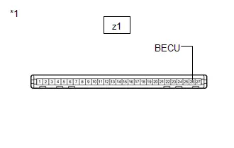
| OK |

| CHECK ECU POWER SOURCE CIRCUIT |
|

| 3. | CHECK HARNESS AND CONNECTOR (BECU SIGNAL CIRCUIT) |
(a) Disconnect the cable from the negative (-) auxiliary battery terminal.
(b) Disconnect the A12 power distribution box assembly connector.
(c) Reconnect the cable to the negative (-) auxiliary battery terminal.
(d) Measure the voltage according to the value(s) in the table below.
Standard Voltage:
 Click Location & Routing(A12) Click Connector(A12)
 | Tester Connection | Condition | Specified Condition |
|---|---|---|
| A12-23 - Body ground | Ignition switch off | 11 to 14 V |
| OK |

| REPLACE POWER DISTRIBUTION BOX ASSEMBLY
|


| NG |

| REPAIR OR REPLACE HARNESS OR CONNECTOR (BECU SIGNAL CIRCUIT) |
Bus Buffer ECU Communication Stop Mode
DESCRIPTION
| Detection Item | Symptom | Trouble Area |
|---|---|---|
| Bus Buffer ECU Communication Stop Mode | Communication stop for "Remote Engine Starter" is indicated on the "Communication Bus Check" screen of the GTS. Click here
|
|

WIRING DIAGRAM
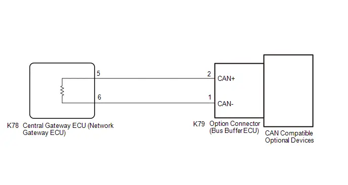
CAUTION / NOTICE / HINT
CAUTION:
When performing the confirmation driving pattern, obey all speed limits and traffic laws.
NOTICE:
-
Because the order of diagnosis is important to allow correct diagnosis, make sure to begin troubleshooting using How to Proceed with Troubleshooting when CAN communication system related DTCs are output.
Click here

- Before measuring the resistance of the CAN bus, turn the ignition switch off and leave the Toyota Prius vehicle for 1 minute or more without operating the key or any switches, or opening or closing the doors. After that, disconnect the cable from the negative (-) auxiliary battery terminal and leave the vehicle for 1 minute or more before measuring the resistance.
-
After the ignition switch is turned off, there may be a waiting time before disconnecting the negative (-) auxiliary battery terminal.
Click here

-
When disconnecting and reconnecting the auxiliary battery.
HINT:
When disconnecting and reconnecting the auxiliary battery, there is an automatic learning function that completes learning when the respective system is used.
Click here


-
Some parts must be initialized and set when replacing or removing and installing parts.
Click here


-
After performing repairs, perform the DTC check procedure and confirm that the DTCs are not output again.
DTC check procedure: Turn the ignition switch to ON and wait for 1 minute or more. Then operate the suspected malfunctioning system and drive the Toyota Prius vehicle at 60 km/h (37 mph) or more for 5 minutes or more.
-
After the repair, perform the CAN bus check and check that all the ECUs and sensors connected to the CAN communication system are displayed as normal.
Click here

- Inspect the fuses for circuits related to this system before performing the following procedure.
-
Before replacing the main body ECU (multiplex network body ECU), refer to Registration.
Click here

- When disconnecting a wire harness of any component connected to the supply power of the integrated capacitor (integration control supply) or when removing the integrated capacitor (integration control supply), make sure to wait 5 minutes or more after turning the ignition switch off for self-diagnosis to complete and the voltage of the integrated capacitor (integration control supply) to discharge.
HINT:
- Before disconnecting related connectors for inspection, push in on each connector body to check that the connector is not loose or disconnected.
- When a connector is disconnected, check that the terminals and connector body are not cracked, deformed or corroded.
PROCEDURE
| 1. | CHECK Toyota Prius Vehicle TYPE |
(a) Check whether dealer installed options that support CAN communication are installed.
| Result | Proceed to |
|---|---|
| Installed | A |
| Not installed | B |
| B |

| GO TO STEP 3 |
|

| 2. | CHECK FOR OPEN IN CAN BUS LINES (OPTION CONNECTOR (BUS BUFFER ECU) MAIN LINE) |
(a) Disconnect the cable from the negative (-) auxiliary battery terminal.
(b) Disconnect the K79 option connector (bus buffer ECU) connector.
(c) Measure the resistance according to the value(s) in the table below.
Standard Resistance:
 Click Location & Routing(K79) Click Connector(K79)
 | Tester Connection | Condition | Specified Condition |
|---|---|---|
| K79-2 (CAN ) - K79-1 (CAN-) | Cable disconnected from negative (-) auxiliary battery terminal | 108 to 132 Ω |
| OK |

| REPAIR OR REPLACE CAN COMPATIBLE OPTIONAL DEVICES |
| NG |

| REPAIR OR REPLACE CAN MAIN BUS LINES OR CONNECTOR (OPTION CONNECTOR (BUS BUFFER ECU)) |
| 3. | CHECK FOR DTC |
(a) Initialize the ECU.
Body Electrical > Central Gateway > Utility| Tester Display |
|---|
| Initialization |
| Tester Display |
|---|
| Initialization |
(b) Clear the DTCs.
Body Electrical > Main Body > Clear DTCs(c) Read the DTCs.
Body Electrical > Main Body > Trouble Codes| Result | Proceed to |
|---|---|
| DTC U111787 is not output from the main body ECU (multiplex network body ECU) | A |
| DTC U111787 is output from the main body ECU (multiplex network body ECU) | B |
| A |

| END |
| B |

| REPLACE MAIN BODY ECU (MULTIPLEX NETWORK BODY ECU)
|


Rear Television Camera Communication Stop Mode
DESCRIPTION
| Detection Item | Symptom | Trouble Area |
|---|---|---|
| Rear Television Camera Communication Stop Mode | Communication stop for "Parking Assist Monitor System / Rear Camera" is indicated on the "Communication Bus Check" screen of the GTS. Click here
|
|

WIRING DIAGRAM
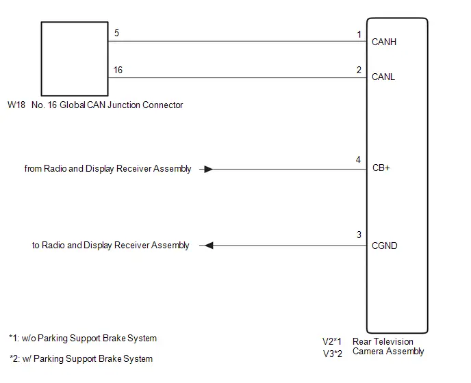
CAUTION / NOTICE / HINT
CAUTION:
When performing the confirmation driving pattern, obey all speed limits and traffic laws.
NOTICE:
-
Because the order of diagnosis is important to allow correct diagnosis, make sure to begin troubleshooting using How to Proceed with Troubleshooting when CAN communication system related DTCs are output.
Click here

- Before measuring the resistance of the CAN bus, turn the ignition switch off and leave the Toyota Prius vehicle for 1 minute or more without operating the key or any switches, or opening or closing the doors. After that, disconnect the cable from the negative (-) auxiliary battery terminal and leave the vehicle for 1 minute or more before measuring the resistance.
-
After the ignition switch is turned off, there may be a waiting time before disconnecting the negative (-) auxiliary battery terminal.
Click here

-
When disconnecting and reconnecting the auxiliary battery.
HINT:
When disconnecting and reconnecting the auxiliary battery, there is an automatic learning function that completes learning when the respective system is used.
Click here


-
Some parts must be initialized and set when replacing or removing and installing parts.
Click here


-
After performing repairs, perform the DTC check procedure and confirm that the DTCs are not output again.
DTC check procedure: Turn the ignition switch to ON and wait for 1 minute or more. Then operate the suspected malfunctioning system and drive the Toyota Prius vehicle at 60 km/h (37 mph) or more for 5 minutes or more.
-
After the repair, perform the CAN bus check and check that all the ECUs and sensors connected to the CAN communication system are displayed as normal.
Click here

- Inspect the fuses for circuits related to this system before performing the following procedure.
HINT:
- Before disconnecting related connectors for inspection, push in on each connector body to check that the connector is not loose or disconnected.
- When a connector is disconnected, check that the terminals and connector body are not cracked, deformed or corroded.
PROCEDURE
| 1. | CHECK Toyota Prius Vehicle TYPE |
(a) Check vehicle type.
| Result | Proceed to |
|---|---|
| w/o Parking Support Brake System | A |
| w/ Parking Support Brake System | B |
| B |

| GO TO STEP 4 |
|

| 2. | CHECK FOR OPEN IN CAN BUS LINES (REAR TELEVISION CAMERA ASSEMBLY BRANCH LINE) |
(a) Disconnect the cable from the negative (-) auxiliary battery terminal.
(b) Disconnect the V2 rear television camera assembly connector.
(c) Measure the resistance according to the value(s) in the table below.
Standard Resistance:
 Click Location & Routing(V2) Click Connector(V2)
 | Tester Connection | Condition | Specified Condition |
|---|---|---|
| V2-1 (CANH) - V2-2 (CANL) | Cable disconnected from negative (-) auxiliary battery terminal | 54 to 69 Ω |
| NG |

| REPAIR OR REPLACE CAN BRANCH LINES OR CONNECTOR (REAR TELEVISION CAMERA ASSEMBLY) |
|

| 3. | CHECK HARNESS AND CONNECTOR (POWER SOURCE CIRCUIT) |
(a) Measure the resistance according to the value(s) in the table below.
Standard Resistance:
 Click Location & Routing(V2) Click Connector(V2)
 | Tester Connection | Condition | Specified Condition |
|---|---|---|
| V2-3 (CGND) - Body ground | Cable disconnected from negative (-) auxiliary battery terminal | Below 1 Ω |
(b) Reconnect the cable to the negative (-) auxiliary battery terminal.
(c) Measure the voltage according to the value(s) in the table below.
Standard Voltage:
 Click Location & Routing(V2) Click Connector(V2)
 | Tester Connection | Condition | Specified Condition |
|---|---|---|
| V2-4 (CB ) - Body ground | Ignition switch ACC | 6 to 9 V |
| OK |

| REPLACE REAR TELEVISION CAMERA ASSEMBLY |
| NG |

| GO TO STEP 6 |
| 4. | CHECK FOR OPEN IN CAN BUS LINES (REAR TELEVISION CAMERA ASSEMBLY BRANCH LINE) |
(a) Disconnect the cable from the negative (-) auxiliary battery terminal.
(b) Disconnect the V3 rear television camera assembly connector.
(c) Measure the resistance according to the value(s) in the table below.
Standard Resistance:
 Click Location & Routing(V3) Click Connector(V3)
 | Tester Connection | Condition | Specified Condition |
|---|---|---|
| V3-1 (CANH) - V3-2 (CANL) | Cable disconnected from negative (-) auxiliary battery terminal | 54 to 69 Ω |
| NG |

| REPAIR OR REPLACE CAN BRANCH LINES OR CONNECTOR (REAR TELEVISION CAMERA ASSEMBLY) |
|

| 5. | CHECK HARNESS AND CONNECTOR (POWER SOURCE CIRCUIT) |
(a) Measure the resistance according to the value(s) in the table below.
Standard Resistance:
 Click Location & Routing(V3) Click Connector(V3)
 | Tester Connection | Condition | Specified Condition |
|---|---|---|
| V3-3 (CGND) - Body ground | Cable disconnected from negative (-) auxiliary battery terminal | Below 1 Ω |
(b) Reconnect the cable to the negative (-) auxiliary battery terminal.
(c) Measure the voltage according to the value(s) in the table below.
Standard Voltage:
 Click Location & Routing(V3) Click Connector(V3)
 | Tester Connection | Condition | Specified Condition |
|---|---|---|
| V3-4 (CB ) - Body ground | Ignition switch ACC | 6 to 9 V |
| OK |

| REPLACE REAR TELEVISION CAMERA ASSEMBLY |
|

| 6. | CHECK HARNESS AND CONNECTOR (REAR TELEVISION CAMERA ASSEMBLY - RADIO AND DISPLAY RECEIVER ASSEMBLY) |
Click here

| OK |

| REPLACE RADIO AND DISPLAY RECEIVER ASSEMBLY |
| NG |

| REPAIR OR REPLACE HARNESS OR CONNECTOR (POWER SOURCE CIRCUIT) |
Check Bus 1 Line
DESCRIPTION
| Symptom | Trouble Area |
|---|---|
| There are ECUs or sensors that display a communication stop on the bus diagnostic screen. Or, there are ECUs or sensors that display communication stop history on the "Detail" screen. |
|
WIRING DIAGRAM
w/ Panoramic View Monitor System: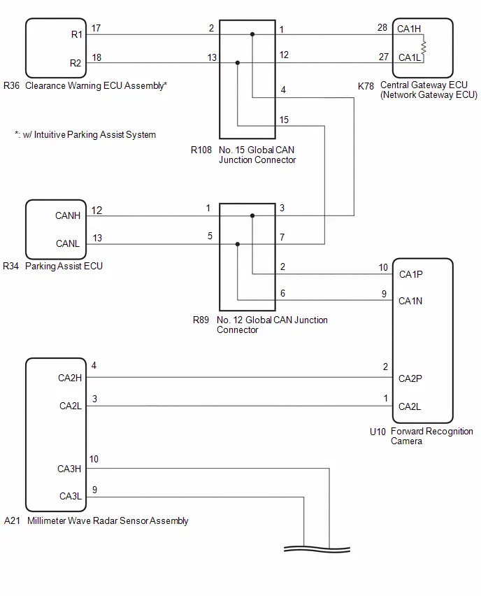 w/o Panoramic View Monitor System:
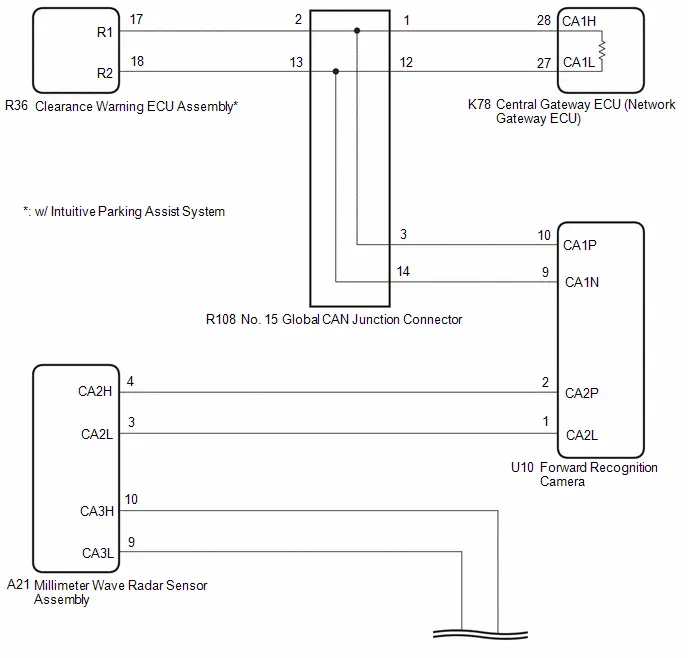 w/ Parking Assist Monitor System:
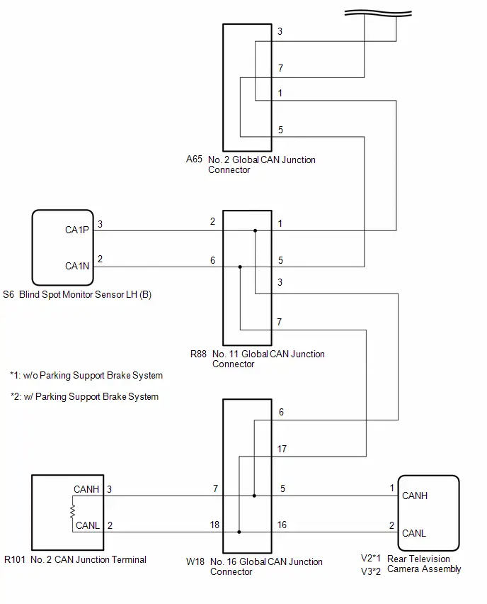 w/o Parking Assist Monitor System:
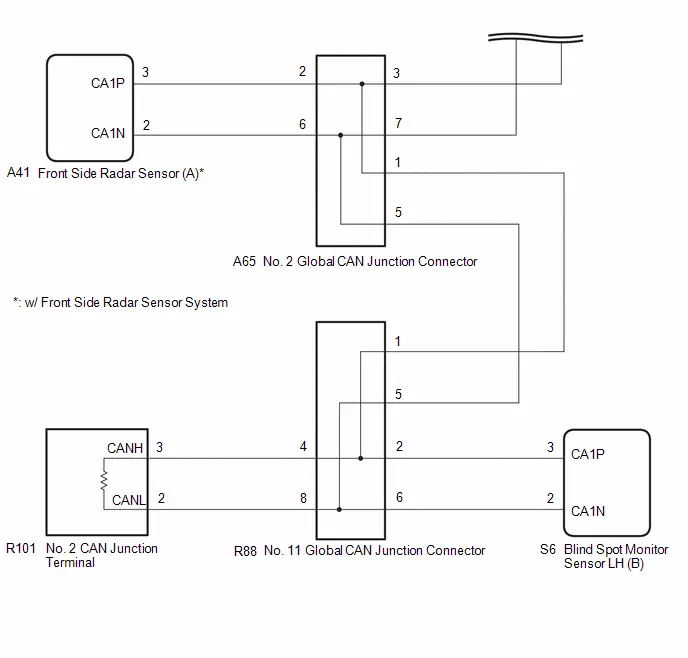
CAUTION / NOTICE / HINT
CAUTION:
When performing the confirmation driving pattern, obey all speed limits and traffic laws.
NOTICE:
-
Because the order of diagnosis is important to allow correct diagnosis, make sure to begin troubleshooting using How to Proceed with Troubleshooting when CAN communication system related DTCs are output.
Click here

- Before measuring the resistance of the CAN bus, turn the ignition switch off and leave the Toyota Prius vehicle for 1 minute or more without operating the key or any switches, or opening or closing the doors. After that, disconnect the cable from the negative (-) auxiliary battery terminal and leave the vehicle for 1 minute or more before measuring the resistance.
-
After the ignition switch is turned off, there may be a waiting time before disconnecting the negative (-) auxiliary battery terminal.
Click here

-
When disconnecting and reconnecting the auxiliary battery.
Click here
HINT:
When disconnecting and reconnecting the auxiliary battery, there is an automatic learning function that completes learning when the respective system is used.
Click here


-
Some parts must be initialized and set when replacing or removing and installing parts.
Click here


-
After performing repairs, perform the DTC check procedure and confirm that the DTCs are not output again.
DTC check procedure: Turn the ignition switch to ON and wait for 1 minute or more. Then operate the suspected malfunctioning system and drive the Toyota Prius vehicle at 60 km/h (37 mph) or more for 5 minutes or more.
-
After the repair, perform the CAN bus check and check that all the ECUs and sensors connected to the CAN communication system are displayed as normal.
Click here

HINT:
- Before disconnecting related connectors for inspection, push in on each connector body to check that the connector is not loose or disconnected.
- When a connector is disconnected, check that the terminals and connector body are not cracked, deformed or corroded.
PROCEDURE
| 1. | CHECK FOR OPEN IN CAN MAIN BUS LINES |
(a) Disconnect the cable from the negative (-) auxiliary battery terminal.
| (b) Measure the resistance according to the value(s) in the table below. Standard Resistance:  Click Location & Routing(K78) Click Connector(K78) Click Location & Routing(K78) Click Connector(K78)
|
|
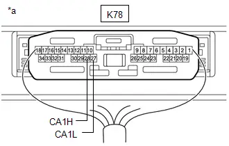
| NG |

| GO TO STEP 107 |
|

| 2. | CHECK FOR SHORT IN CAN BUS LINES |
| (a) Measure the resistance according to the value(s) in the table below. Standard Resistance:  Click Location & Routing(K78) Click Connector(K78) Click Location & Routing(K78) Click Connector(K78)
|
|

| NG |

| GO TO STEP 73 |
|

| 3. | CHECK FOR SHORT TO B IN CAN BUS LINE |
(a) Measure the resistance according to the value(s) in the table below.
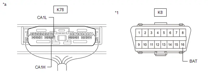
| *1 | DLC3 | - | - |
| *a | Component with harness connected (Central Gateway ECU (Network Gateway ECU)) | - | - |
Standard Resistance:
 Click Location & Routing(K78,K8) Click Connector(K78) Click Connector(K8)
 | Tester Connection | Condition | Specified Condition |
|---|---|---|
| K78-28 (CA1H) - K8-16 (BAT) | Cable disconnected from negative (-) auxiliary battery terminal | 6 kΩ or higher |
| K78-27 (CA1L) - K8-16 (BAT) |
| NG |

| GO TO STEP 39 |
|

| 4. | CHECK FOR SHORT TO GND IN CAN BUS LINE |
(a) Measure the resistance according to the value(s) in the table below.
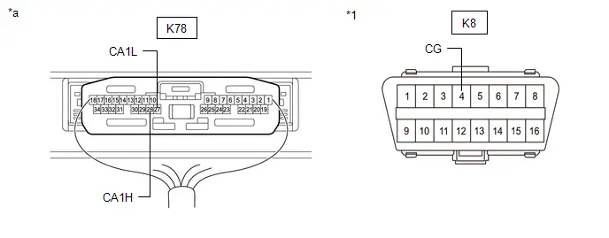
| *1 | DLC3 | - | - |
| *a | Component with harness connected (Central Gateway ECU (Network Gateway ECU)) | - | - |
Standard Resistance:
 Click Location & Routing(K78,K8) Click Connector(K78) Click Connector(K8)
 | Tester Connection | Condition | Specified Condition |
|---|---|---|
| K78-28 (CA1H) - K8-4 (CG) | Cable disconnected from negative (-) auxiliary battery terminal | 200 Ω or higher |
| K78-27 (CA1L) - K8-4 (CG) |
| OK |

| REPLACE CENTRAL GATEWAY ECU (NETWORK GATEWAY ECU) |
|

| 5. | CHECK FOR SHORT TO GND IN CAN BUS LINE (NO. 15 GLOBAL CAN JUNCTION CONNECTOR - CENTRAL GATEWAY ECU (NETWORK GATEWAY ECU)) |
(a) Disconnect the R108 No. 15 global CAN junction connector.
(b) Measure the resistance according to the value(s) in the table below.
Standard Resistance:
 Click Location & Routing(R108,K8) Click Connector(R108) Click Connector(K8)
 | Tester Connection | Condition | Specified Condition |
|---|---|---|
| R108-1 (CANH) - K8-4 (CG) | Cable disconnected from negative (-) auxiliary battery terminal | 200 Ω or higher |
| R108-12 (CANL) - K8-4 (CG) |
| NG |

| GO TO STEP 8 |
|

| 6. | CHECK Toyota Prius Vehicle TYPE |
(a) Check vehicle type.
| Result | Proceed to |
|---|---|
| w/ Panoramic View Monitor System | A |
| w/o Panoramic View Monitor System | B |
| B |

| GO TO STEP 14 |
|

| 7. | CHECK FOR SHORT TO GND IN CAN BUS LINE (NO. 15 GLOBAL CAN JUNCTION CONNECTOR - NO. 12 GLOBAL CAN JUNCTION CONNECTOR) |
(a) Measure the resistance according to the value(s) in the table below.
Standard Resistance:
 Click Location & Routing(R108,K8) Click Connector(R108) Click Connector(K8)
 | Tester Connection | Condition | Specified Condition |
|---|---|---|
| R108-4(CANH) - K8-4 (CG) | Cable disconnected from negative (-) auxiliary battery terminal | 200 Ω or higher |
| R108-15 (CANL) - K8-4 (CG) |
| OK |

| GO TO STEP 15 |
| NG |

| GO TO STEP 9 |
| 8. | CHECK FOR SHORT TO GND IN CAN BUS LINE (NO. 15 GLOBAL CAN JUNCTION CONNECTOR - CENTRAL GATEWAY ECU (NETWORK GATEWAY ECU)) |
(a) Disconnect the K78 central gateway ECU (network gateway ECU) connector.
(b) Measure the resistance according to the value(s) in the table below.
Standard Resistance:
 Click Location & Routing(R108,K8) Click Connector(R108) Click Connector(K8)
 | Tester Connection | Condition | Specified Condition |
|---|---|---|
| R108-1 (CANH) - K8-4 (CG) | Cable disconnected from negative (-) auxiliary battery terminal | 200 Ω or higher |
| R108-12 (CANL) - K8-4 (CG) |
| OK |

| REPLACE CENTRAL GATEWAY ECU (NETWORK GATEWAY ECU) |
| NG |

| REPAIR OR REPLACE CAN MAIN BUS LINE OR CONNECTOR (NO. 15 GLOBAL CAN JUNCTION CONNECTOR - CENTRAL GATEWAY ECU (NETWORK GATEWAY ECU)) |
| 9. | CHECK FOR SHORT TO GND IN CAN BUS LINE (NO. 12 GLOBAL CAN JUNCTION CONNECTOR - NO. 15 GLOBAL CAN JUNCTION CONNECTOR) |
(a) Disconnect the R89 No. 12 global CAN junction connector.
(b) Measure the resistance according to the value(s) in the table below.
Standard Resistance:
 Click Location & Routing(R89,K8) Click Connector(R89) Click Connector(K8)
 | Tester Connection | Condition | Specified Condition |
|---|---|---|
| R89-3 (CANH) - K8-4 (CG) | Cable disconnected from negative (-) auxiliary battery terminal | 200 Ω or higher |
| R89-7 (CANL) - K8-4 (CG) |
| NG |

| REPAIR OR REPLACE CAN MAIN BUS LINE OR CONNECTOR (NO. 12 GLOBAL CAN JUNCTION CONNECTOR - NO. 15 GLOBAL CAN JUNCTION CONNECTOR) |
|

| 10. | CHECK FOR SHORT TO GND IN CAN BUS LINE (NO. 12 GLOBAL CAN JUNCTION CONNECTOR - FORWARD RECOGNITION CAMERA) |
(a) Measure the resistance according to the value(s) in the table below.
Standard Resistance:
 Click Location & Routing(R89,K8) Click Connector(R89) Click Connector(K8)
 | Tester Connection | Condition | Specified Condition |
|---|---|---|
| R89-2 (CANH) - K8-4 (CG) | Cable disconnected from negative (-) auxiliary battery terminal | 200 Ω or higher |
| R89-6 (CANL) - K8-4 (CG) |
| NG |

| GO TO STEP 12 |
|

| 11. | CHECK FOR SHORT TO GND IN CAN BUS LINE (NO. 12 GLOBAL CAN JUNCTION CONNECTOR - PARKING ASSIST ECU) |
(a) Measure the resistance according to the value(s) in the table below.
Standard Resistance:
 Click Location & Routing(R89,K8) Click Connector(R89) Click Connector(K8)
 | Tester Connection | Condition | Specified Condition |
|---|---|---|
| R89-1 (CANH) - K8-4 (CG) | Cable disconnected from negative (-) auxiliary battery terminal | 200 Ω or higher |
| R89-5 (CANL) - K8-4 (CG) |
| OK |

| REPLACE NO. 12 GLOBAL CAN JUNCTION CONNECTOR |
| NG |

| GO TO STEP 13 |
| 12. | CHECK FOR SHORT TO GND IN CAN BUS LINE (FORWARD RECOGNITION CAMERA - NO. 12 GLOBAL CAN JUNCTION CONNECTOR) |
(a) Disconnect the U10 forward recognition camera connector.
(b) Measure the resistance according to the value(s) in the table below.
Standard Resistance:
 Click Location & Routing(U10,K8) Click Connector(U10) Click Connector(K8)
 | Tester Connection | Condition | Specified Condition |
|---|---|---|
| U10-10 (CA1P) - K8-4 (CG) | Cable disconnected from negative (-) auxiliary battery terminal | 200 Ω or higher |
| U10-9 (CA1N) - K8-4 (CG) |
| OK |

| GO TO STEP 19 |
| NG |

| REPAIR OR REPLACE CAN MAIN BUS LINE OR CONNECTOR (FORWARD RECOGNITION CAMERA - NO. 12 GLOBAL CAN JUNCTION CONNECTOR) |
| 13. | CHECK FOR SHORT TO GND IN CAN BUS LINE (NO. 12 GLOBAL CAN JUNCTION CONNECTOR - PARKING ASSIST ECU) |
(a) Disconnect the R34 parking assist ECU connector.
(b) Measure the resistance according to the value(s) in the table below.
Standard Resistance:
 Click Location & Routing(R89,K8) Click Connector(R89) Click Connector(K8)
 | Tester Connection | Condition | Specified Condition |
|---|---|---|
| R89-1 (CANH) - K8-4 (CG) | Cable disconnected from negative (-) auxiliary battery terminal | 200 Ω or higher |
| R89-5 (CANL) - K8-4 (CG) |
| OK |

| REPLACE PARKING ASSIST ECU |
| NG |

| REPAIR OR REPLACE CAN BRANCH LINE OR CONNECTOR (NO. 12 GLOBAL CAN JUNCTION CONNECTOR - PARKING ASSIST ECU) |
| 14. | CHECK FOR SHORT TO GND IN CAN BUS LINE (NO. 15 GLOBAL CAN JUNCTION CONNECTOR - FORWARD RECOGNITION CAMERA) |
(a) Measure the resistance according to the value(s) in the table below.
Standard Resistance:
 Click Location & Routing(R108,K8) Click Connector(R108) Click Connector(K8)
 | Tester Connection | Condition | Specified Condition |
|---|---|---|
| R108-3 (CANH) - K8-4 (CG) | Cable disconnected from negative (-) auxiliary battery terminal | 200 Ω or higher |
| R108-14 (CANL) - K8-4 (CG) |
| NG |

| GO TO STEP 18 |
|

| 15. | CHECK Toyota Prius Vehicle TYPE |
(a) Check vehicle type.
| Result | Proceed to |
|---|---|
| w/ Intuitive Parking Assist System | A |
| w/o Intuitive Parking Assist System | B |
| B |

| REPLACE NO. 15 GLOBAL CAN JUNCTION CONNECTOR |
|

| 16. | CHECK FOR SHORT TO GND IN CAN BUS LINE (NO. 15 GLOBAL CAN JUNCTION CONNECTOR - CLEARANCE WARNING ECU ASSEMBLY) |
(a) Measure the resistance according to the value(s) in the table below.
Standard Resistance:
 Click Location & Routing(R108,K8) Click Connector(R108) Click Connector(K8)
 | Tester Connection | Condition | Specified Condition |
|---|---|---|
| R108-2 (CANH) - K8-4 (CG) | Cable disconnected from negative (-) auxiliary battery terminal | 200 Ω or higher |
| R108-13 (CANL) - K8-4 (CG) |
| OK |

| REPLACE NO. 15 GLOBAL CAN JUNCTION CONNECTOR |
|

| 17. | CHECK FOR SHORT TO GND IN CAN BUS LINE (NO. 15 GLOBAL CAN JUNCTION CONNECTOR - CLEARANCE WARNING ECU ASSEMBLY) |
(a) Disconnect the R36 clearance warning ECU assembly connector.
(b) Measure the resistance according to the value(s) in the table below.
Standard Resistance:
 Click Location & Routing(R108,K8) Click Connector(R108) Click Connector(K8)
 | Tester Connection | Condition | Specified Condition |
|---|---|---|
| R108-2 (CANH) - K8-4 (CG) | Cable disconnected from negative (-) auxiliary battery terminal | 200 Ω or higher |
| R108-13 (CANL) - K8-4 (CG) |
| OK |

| REPLACE CLEARANCE WARNING ECU ASSEMBLY |
| NG |

| REPAIR OR REPLACE CAN BRANCH LINE OR CONNECTOR (NO. 15 GLOBAL CAN JUNCTION CONNECTOR - CLEARANCE WARNING ECU ASSEMBLY) |
| 18. | CHECK FOR SHORT TO GND IN CAN BUS LINE (FORWARD RECOGNITION CAMERA - NO. 15 GLOBAL CAN JUNCTION CONNECTOR) |
(a) Disconnect the U10 forward recognition camera connector.
(b) Measure the resistance according to the value(s) in the table below.
Standard Resistance:
 Click Location & Routing(U10,K8) Click Connector(U10) Click Connector(K8)
 | Tester Connection | Condition | Specified Condition |
|---|---|---|
| U10-10 (CA1P) - K8-4 (CG) | Cable disconnected from negative (-) auxiliary battery terminal | 200 Ω or higher |
| U10-9 (CA1N) - K8-4 (CG) |
| NG |

| REPAIR OR REPLACE CAN MAIN BUS LINE OR CONNECTOR (FORWARD RECOGNITION CAMERA - NO. 15 GLOBAL CAN JUNCTION CONNECTOR) |
|

| 19. | CHECK FOR SHORT TO GND IN CAN BUS LINE (FORWARD RECOGNITION CAMERA - MILLIMETER WAVE RADAR SENSOR ASSEMBLY) |
(a) Measure the resistance according to the value(s) in the table below.
Standard Resistance:
 Click Location & Routing(U10,K8) Click Connector(U10) Click Connector(K8)
 | Tester Connection | Condition | Specified Condition |
|---|---|---|
| U10-2 (CA2P) - K8-4 (CG) | Cable disconnected from negative (-) auxiliary battery terminal | 200 Ω or higher |
| U10-1 (CA2L) - K8-4 (CG) |
| OK |

| REPLACE FORWARD RECOGNITION CAMERA
|


|

| 20. | CHECK FOR SHORT TO GND IN CAN BUS LINE (MILLIMETER WAVE RADAR SENSOR ASSEMBLY - FORWARD RECOGNITION CAMERA) |
(a) Disconnect the A21 millimeter wave radar sensor assembly connector.
(b) Measure the resistance according to the value(s) in the table below.
Standard Resistance:
 Click Location & Routing(A21,K8) Click Connector(A21) Click Connector(K8)
 | Tester Connection | Condition | Specified Condition |
|---|---|---|
| A21-4 (CA2H) - K8-4 (CG) | Cable disconnected from negative (-) auxiliary battery terminal | 200 Ω or higher |
| A21-3 (CA2L) - K8-4 (CG) |
| NG |

| REPAIR OR REPLACE CAN MAIN BUS LINE OR CONNECTOR (MILLIMETER WAVE RADAR SENSOR ASSEMBLY - FORWARD RECOGNITION CAMERA) |
|

| 21. | CHECK FOR SHORT TO GND IN CAN BUS LINE (MILLIMETER WAVE RADAR SENSOR ASSEMBLY - NO. 2 GLOBAL CAN JUNCTION CONNECTOR) |
(a) Measure the resistance according to the value(s) in the table below.
Standard Resistance:
 Click Location & Routing(A21,K8) Click Connector(A21) Click Connector(K8)
 | Tester Connection | Condition | Specified Condition |
|---|---|---|
| A21-10 (CA3H) - K8-4 (CG) | Cable disconnected from negative (-) auxiliary battery terminal | 200 Ω or higher |
| A21-9 (CA3L) - K8-4 (CG) |
| OK |

| REPLACE MILLIMETER WAVE RADAR SENSOR ASSEMBLY
|


|

| 22. | CHECK FOR SHORT TO GND IN CAN BUS LINE (NO. 2 GLOBAL CAN JUNCTION CONNECTOR - MILLIMETER WAVE RADAR SENSOR ASSEMBLY) |
(a) Disconnect the A65 No. 2 global CAN junction connector.
(b) Measure the resistance according to the value(s) in the table below.
Standard Resistance:
 Click Location & Routing(A65,K8) Click Connector(A65) Click Connector(K8)
 | Tester Connection | Condition | Specified Condition |
|---|---|---|
| A65-3 (CANH) - K8-4 (CG) | Cable disconnected from negative (-) auxiliary battery terminal | 200 Ω or higher |
| A65-7 (CANL) - K8-4 (CG) |
| NG |

| REPAIR OR REPLACE CAN MAIN BUS LINE OR CONNECTOR (NO. 2 GLOBAL CAN JUNCTION CONNECTOR - MILLIMETER WAVE RADAR SENSOR ASSEMBLY) |
|

| 23. | CHECK FOR SHORT TO GND IN CAN BUS LINE (NO. 2 GLOBAL CAN JUNCTION CONNECTOR - NO. 11 GLOBAL CAN JUNCTION CONNECTOR) |
(a) Measure the resistance according to the value(s) in the table below.
Standard Resistance:
 Click Location & Routing(A65,K8) Click Connector(A65) Click Connector(K8)
 | Tester Connection | Condition | Specified Condition |
|---|---|---|
| A65-1 (CANH) - K8-4 (CG) | Cable disconnected from negative (-) auxiliary battery terminal | 200 Ω or higher |
| A65-5 (CANL) - K8-4 (CG) |
| NG |

| GO TO STEP 27 |
|

| 24. | CHECK Toyota Prius Vehicle TYPE |
(a) Check vehicle type.
| Result | Proceed to |
|---|---|
| w/ Front Side Radar Sensor System | A |
| w/o Front Side Radar Sensor System | B |
| B |

| REPLACE NO. 2 GLOBAL CAN JUNCTION CONNECTOR |
|

| 25. | CHECK FOR SHORT TO GND IN CAN BUS LINE (NO. 2 GLOBAL CAN JUNCTION CONNECTOR - FRONT SIDE RADAR SENSOR (A)) |
(a) Measure the resistance according to the value(s) in the table below.
Standard Resistance:
 Click Location & Routing(A65,K8) Click Connector(A65) Click Connector(K8)
 | Tester Connection | Condition | Specified Condition |
|---|---|---|
| A65-2 (CANH) - K8-4 (CG) | Cable disconnected from negative (-) auxiliary battery terminal | 200 Ω or higher |
| A65-6 (CANL) - K8-4 (CG) |
| OK |

| REPLACE NO. 2 GLOBAL CAN JUNCTION CONNECTOR |
|

| 26. | CHECK FOR SHORT TO GND IN CAN BUS LINE (NO. 2 GLOBAL CAN JUNCTION CONNECTOR - FRONT SIDE RADAR SENSOR (A)) |
(a) Disconnect the A41 front side radar sensor (A) connector.
(b) Measure the resistance according to the value(s) in the table below.
Standard Resistance:
 Click Location & Routing(A65,K8) Click Connector(A65) Click Connector(K8)
 | Tester Connection | Condition | Specified Condition |
|---|---|---|
| A65-2 (CANH) - K8-4 (CG) | Cable disconnected from negative (-) auxiliary battery terminal | 200 Ω or higher |
| A65-6 (CANL) - K8-4 (CG) |
| OK |

| REPLACE FRONT SIDE RADAR SENSOR (A)
|


| NG |

| REPAIR OR REPLACE CAN BRANCH LINE OR CONNECTOR (NO. 2 GLOBAL CAN JUNCTION CONNECTOR - FRONT SIDE RADAR SENSOR (A)) |
| 27. | CHECK FOR SHORT TO GND IN CAN BUS LINE (NO. 11 GLOBAL CAN JUNCTION CONNECTOR - NO. 2 GLOBAL CAN JUNCTION CONNECTOR) |
(a) Disconnect the R88 No. 11 global CAN junction connector.
(b) Measure the resistance according to the value(s) in the table below.
Standard Resistance:
 Click Location & Routing(R88,K8) Click Connector(R88) Click Connector(K8)
 | Tester Connection | Condition | Specified Condition |
|---|---|---|
| R88-1 (CANH) - K8-4 (CG) | Cable disconnected from negative (-) auxiliary battery terminal | 200 Ω or higher |
| R88-5 (CANL) - K8-4 (CG) |
| NG |

| REPAIR OR REPLACE CAN MAIN BUS LINE OR CONNECTOR (NO. 11 GLOBAL CAN JUNCTION CONNECTOR - NO. 2 GLOBAL CAN JUNCTION CONNECTOR) |
|

| 28. | CHECK Toyota Prius Vehicle TYPE |
(a) Check vehicle type.
| Result | Proceed to |
|---|---|
| w/ Parking Assist Monitor System | A |
| w/o Parking Assist Monitor System | B |
| B |

| GO TO STEP 35 |
|

| 29. | CHECK FOR SHORT TO GND IN CAN BUS LINE (NO. 11 GLOBAL CAN JUNCTION CONNECTOR - NO. 16 GLOBAL CAN JUNCTION CONNECTOR) |
(a) Measure the resistance according to the value(s) in the table below.
Standard Resistance:
 Click Location & Routing(R88,K8) Click Connector(R88) Click Connector(K8)
 | Tester Connection | Condition | Specified Condition |
|---|---|---|
| R88-3 (CANH) - K8-4 (CG) | Cable disconnected from negative (-) auxiliary battery terminal | 200 Ω or higher |
| R88-7 (CANL) - K8-4 (CG) |
| OK |

| GO TO STEP 36 |
|

| 30. | CHECK FOR SHORT TO GND IN CAN BUS LINE (NO. 16 GLOBAL CAN JUNCTION CONNECTOR - NO. 11 GLOBAL CAN JUNCTION CONNECTOR) |
(a) Disconnect the W18 No. 16 global CAN junction connector.
(b) Measure the resistance according to the value(s) in the table below.
Standard Resistance:
 Click Location & Routing(W18,K8) Click Connector(W18) Click Connector(K8)
 | Tester Connection | Condition | Specified Condition |
|---|---|---|
| W18-6 (CANH) - K8-4 (CG) | Cable disconnected from negative (-) auxiliary battery terminal | 200 Ω or higher |
| W18-17 (CANL) - K8-4 (CG) |
| NG |

| REPAIR OR REPLACE CAN MAIN BUS LINE OR CONNECTOR (NO. 16 GLOBAL CAN JUNCTION CONNECTOR - NO. 11 GLOBAL CAN JUNCTION CONNECTOR) |
|

| 31. | CHECK FOR SHORT TO GND IN CAN BUS LINE (NO. 16 GLOBAL CAN JUNCTION CONNECTOR - NO. 2 CAN JUNCTION TERMINAL) |
(a) Measure the resistance according to the value(s) in the table below.
Standard Resistance:
 Click Location & Routing(W18,K8) Click Connector(W18) Click Connector(K8)
 | Tester Connection | Condition | Specified Condition |
|---|---|---|
| W18-7 (CANH) - K8-4 (CG) | Cable disconnected from negative (-) auxiliary battery terminal | 200 Ω or higher |
| W18-18 (CANL) - K8-4 (CG) |
| NG |

| GO TO STEP 33 |
|

| 32. | CHECK FOR SHORT TO GND IN CAN BUS LINE (NO. 16 GLOBAL CAN JUNCTION CONNECTOR - REAR TELEVISION CAMERA ASSEMBLY) |
(a) Measure the resistance according to the value(s) in the table below.
Standard Resistance:
 Click Location & Routing(W18,K8) Click Connector(W18) Click Connector(K8)
 | Tester Connection | Condition | Specified Condition |
|---|---|---|
| W18-5 (CANH) - K8-4 (CG) | Cable disconnected from negative (-) auxiliary battery terminal | 200 Ω or higher |
| W18-16 (CANL) - K8-4 (CG) |
| OK |

| REPLACE NO. 16 GLOBAL CAN JUNCTION CONNECTOR |
| NG |

| GO TO STEP 34 |
| 33. | CHECK FOR SHORT TO GND IN CAN BUS LINE (NO. 16 GLOBAL CAN JUNCTION CONNECTOR - NO. 2 CAN JUNCTION TERMINAL) |
(a) Disconnect the R101 No. 2 CAN junction terminal connector.
(b) Measure the resistance according to the value(s) in the table below.
Standard Resistance:
 Click Location & Routing(W18,K8) Click Connector(W18) Click Connector(K8)
 | Tester Connection | Condition | Specified Condition |
|---|---|---|
| W18-7 (CANH) - K8-4 (CG) | Cable disconnected from negative (-) auxiliary battery terminal | 200 Ω or higher |
| W18-18 (CANL) - K8-4 (CG) |
| OK |

| REPLACE NO. 2 CAN JUNCTION TERMINAL |
| NG |

| REPAIR OR REPLACE CAN MAIN BUS LINE OR CONNECTOR (NO. 16 GLOBAL CAN JUNCTION CONNECTOR - NO. 2 CAN JUNCTION TERMINAL) |
| 34. | CHECK FOR SHORT TO GND IN CAN BUS LINE (NO. 16 GLOBAL CAN JUNCTION CONNECTOR - REAR TELEVISION CAMERA ASSEMBLY) |
(a) Disconnect the V2 or V3 rear television camera assembly connector.
(b) Measure the resistance according to the value(s) in the table below.
Standard Resistance:
 Click Location & Routing(W18,K8) Click Connector(W18) Click Connector(K8)
 | Tester Connection | Condition | Specified Condition |
|---|---|---|
| W18-5 (CANH) - K8-4 (CG) | Cable disconnected from negative (-) auxiliary battery terminal | 200 Ω or higher |
| W18-16 (CANL) - K8-4 (CG) |
| OK |

| REPLACE REAR TELEVISION CAMERA ASSEMBLY |
| NG |

| REPAIR OR REPLACE CAN BRANCH LINE OR CONNECTOR (NO. 16 GLOBAL CAN JUNCTION CONNECTOR - REAR TELEVISION CAMERA ASSEMBLY) |
| 35. | CHECK FOR SHORT TO GND IN CAN BUS LINE (NO. 11 GLOBAL CAN JUNCTION CONNECTOR - NO. 2 CAN JUNCTION TERMINAL) |
(a) Measure the resistance according to the value(s) in the table below.
Standard Resistance:
 Click Location & Routing(R88,K8) Click Connector(R88) Click Connector(K8)
 | Tester Connection | Condition | Specified Condition |
|---|---|---|
| R88-4 (CANH) - K8-4 (CG) | Cable disconnected from negative (-) auxiliary battery terminal | 200 Ω or higher |
| R88-8 (CANL) - K8-4 (CG) |
| NG |

| GO TO STEP 37 |
|

| 36. | CHECK FOR SHORT TO GND IN CAN BUS LINE (NO. 11 GLOBAL CAN JUNCTION CONNECTOR - BLIND SPOT MONITOR SENSOR LH (B)) |
(a) Measure the resistance according to the value(s) in the table below.
Standard Resistance:
 Click Location & Routing(R88,K8) Click Connector(R88) Click Connector(K8)
 | Tester Connection | Condition | Specified Condition |
|---|---|---|
| R88-2 (CANH) - K8-4 (CG) | Cable disconnected from negative (-) auxiliary battery terminal | 200 Ω or higher |
| R88-6 (CANL) - K8-4 (CG) |
| OK |

| REPLACE NO. 11 GLOBAL CAN JUNCTION CONNECTOR |
| NG |

| GO TO STEP 38 |
| 37. | CHECK FOR SHORT TO GND IN CAN BUS LINE (NO. 11 GLOBAL CAN JUNCTION CONNECTOR - NO. 2 CAN JUNCTION TERMINAL) |
(a) Disconnect the R101 No. 2 CAN junction terminal connector.
(b) Measure the resistance according to the value(s) in the table below.
Standard Resistance:
 Click Location & Routing(R88,K8) Click Connector(R88) Click Connector(K8)
 | Tester Connection | Condition | Specified Condition |
|---|---|---|
| R88-4 (CANH) - K8-4 (CG) | Cable disconnected from negative (-) auxiliary battery terminal | 200 Ω or higher |
| R88-8 (CANL) - K8-4 (CG) |
| OK |

| REPLACE NO. 2 CAN JUNCTION TERMINAL |
| NG |

| REPAIR OR REPLACE CAN MAIN BUS LINE OR CONNECTOR (NO. 11 GLOBAL CAN JUNCTION CONNECTOR - NO. 2 CAN JUNCTION TERMINAL) |
| 38. | CHECK FOR SHORT TO GND IN CAN BUS LINE (NO. 11 GLOBAL CAN JUNCTION CONNECTOR - BLIND SPOT MONITOR SENSOR LH (B)) |
(a) Disconnect the S6 blind spot monitor sensor LH (B) connector.
(b) Measure the resistance according to the value(s) in the table below.
Standard Resistance:
 Click Location & Routing(R88,K8) Click Connector(R88) Click Connector(K8)
 | Tester Connection | Condition | Specified Condition |
|---|---|---|
| R88-2 (CANH) - K8-4 (CG) | Cable disconnected from negative (-) auxiliary battery terminal | 200 Ω or higher |
| R88-6 (CANL) - K8-4 (CG) |
| OK |

| REPLACE BLIND SPOT MONITOR SENSOR LH (B)
|


| NG |

| REPAIR OR REPLACE CAN BRANCH LINE OR CONNECTOR (NO. 11 GLOBAL CAN JUNCTION CONNECTOR - BLIND SPOT MONITOR SENSOR LH (B)) |
| 39. | CHECK FOR SHORT TO B IN CAN BUS LINE (NO. 15 GLOBAL CAN JUNCTION CONNECTOR - CENTRAL GATEWAY ECU (NETWORK GATEWAY ECU)) |
(a) Disconnect the R108 No. 15 global CAN junction connector.
(b) Measure the resistance according to the value(s) in the table below.
Standard Resistance:
 Click Location & Routing(R108,K8) Click Connector(R108) Click Connector(K8)
 | Tester Connection | Condition | Specified Condition |
|---|---|---|
| R108-1 (CANH) - K8-16 (BAT) | Cable disconnected from negative (-) auxiliary battery terminal | 6 kΩ or higher |
| R108-12 (CANL) - K8-16 (BAT) |
| NG |

| GO TO STEP 42 |
|

| 40. | CHECK Toyota Prius Vehicle TYPE |
(a) Check vehicle type.
| Result | Proceed to |
|---|---|
| w/ Panoramic View Monitor System | A |
| w/o Panoramic View Monitor System | B |
| B |

| GO TO STEP 48 |
|

| 41. | CHECK FOR SHORT TO B IN CAN BUS LINE (NO. 15 GLOBAL CAN JUNCTION CONNECTOR - NO. 12 GLOBAL CAN JUNCTION CONNECTOR) |
(a) Measure the resistance according to the value(s) in the table below.
Standard Resistance:
 Click Location & Routing(R108,K8) Click Connector(R108) Click Connector(K8)
 | Tester Connection | Condition | Specified Condition |
|---|---|---|
| R108-4 (CANH) - K8-16 (BAT) | Cable disconnected from negative (-) auxiliary battery terminal | 6 kΩ or higher |
| R108-15 (CANL) - K8-16 (BAT) |
| OK |

| GO TO STEP 49 |
| NG |

| GO TO STEP 43 |
| 42. | CHECK FOR SHORT TO B IN CAN BUS LINE (NO. 15 GLOBAL CAN JUNCTION CONNECTOR - CENTRAL GATEWAY ECU (NETWORK GATEWAY ECU)) |
(a) Disconnect the K78 central gateway ECU (network gateway ECU) connector.
(b) Measure the resistance according to the value(s) in the table below.
Standard Resistance:
 Click Location & Routing(R108,K8) Click Connector(R108) Click Connector(K8)
 | Tester Connection | Condition | Specified Condition |
|---|---|---|
| R108-1 (CANH) - K8-16 (BAT) | Cable disconnected from negative (-) auxiliary battery terminal | 6 kΩ or higher |
| R108-12 (CANL) - K8-16 (BAT) |
| OK |

| REPLACE CENTRAL GATEWAY ECU (NETWORK GATEWAY ECU) |
| NG |

| REPAIR OR REPLACE CAN MAIN BUS LINE OR CONNECTOR (NO. 15 GLOBAL CAN JUNCTION CONNECTOR - CENTRAL GATEWAY ECU (NETWORK GATEWAY ECU)) |
| 43. | CHECK FOR SHORT TO B IN CAN BUS LINE (NO. 12 GLOBAL CAN JUNCTION CONNECTOR - NO. 15 GLOBAL CAN JUNCTION CONNECTOR) |
(a) Disconnect the R89 No. 12 global CAN junction connector.
(b) Measure the resistance according to the value(s) in the table below.
Standard Resistance:
 Click Location & Routing(R89,K8) Click Connector(R89) Click Connector(K8)
 | Tester Connection | Condition | Specified Condition |
|---|---|---|
| R89-3 (CANH) - K8-16 (BAT) | Cable disconnected from negative (-) auxiliary battery terminal | 6 kΩ or higher |
| R89-7 (CANL) - K8-16 (BAT) |
| NG |

| REPAIR OR REPLACE CAN MAIN BUS LINE OR CONNECTOR (NO. 12 GLOBAL CAN JUNCTION CONNECTOR - NO. 15 GLOBAL CAN JUNCTION CONNECTOR) |
|

| 44. | CHECK FOR SHORT TO B IN CAN BUS LINE (NO. 12 GLOBAL CAN JUNCTION CONNECTOR - FORWARD RECOGNITION CAMERA) |
(a) Measure the resistance according to the value(s) in the table below.
Standard Resistance:
 Click Location & Routing(R89,K8) Click Connector(R89) Click Connector(K8)
 | Tester Connection | Condition | Specified Condition |
|---|---|---|
| R89-2 (CANH) - K8-16 (BAT) | Cable disconnected from negative (-) auxiliary battery terminal | 6 kΩ or higher |
| R89-6 (CANL) - K8-16 (BAT) |
| NG |

| GO TO STEP 46 |
|

| 45. | CHECK FOR SHORT TO B IN CAN BUS LINE (NO. 12 GLOBAL CAN JUNCTION CONNECTOR - PARKING ASSIST ECU) |
(a) Measure the resistance according to the value(s) in the table below.
Standard Resistance:
 Click Location & Routing(R89,K8) Click Connector(R89) Click Connector(K8)
 | Tester Connection | Condition | Specified Condition |
|---|---|---|
| R89-1 (CANH) - K8-16 (BAT) | Cable disconnected from negative (-) auxiliary battery terminal | 6 kΩ or higher |
| R89-5 (CANL) - K8-16 (BAT) |
| OK |

| REPLACE NO. 12 GLOBAL CAN JUNCTION CONNECTOR |
| NG |

| GO TO STEP 47 |
| 46. | CHECK FOR SHORT TO B IN CAN BUS LINE (FORWARD RECOGNITION CAMERA - NO. 12 GLOBAL CAN JUNCTION CONNECTOR) |
(a) Disconnect the U10 forward recognition camera connector.
(b) Measure the resistance according to the value(s) in the table below.
Standard Resistance:
 Click Location & Routing(U10,K8) Click Connector(U10) Click Connector(K8)
 | Tester Connection | Condition | Specified Condition |
|---|---|---|
| U10-10 (CA1P) - K8-16 (BAT) | Cable disconnected from negative (-) auxiliary battery terminal | 6 kΩ or higher |
| U10-9 (CA1N) - K8-16 (BAT) |
| OK |

| GO TO STEP 53 |
| NG |

| REPAIR OR REPLACE CAN MAIN BUS LINE OR CONNECTOR (FORWARD RECOGNITION CAMERA - NO. 12 GLOBAL CAN JUNCTION CONNECTOR) |
| 47. | CHECK FOR SHORT TO B IN CAN BUS LINE (NO. 12 GLOBAL CAN JUNCTION CONNECTOR - PARKING ASSIST ECU) |
(a) Disconnect the R34 parking assist ECU connector.
(b) Measure the resistance according to the value(s) in the table below.
Standard Resistance:
 Click Location & Routing(R89,K8) Click Connector(R89) Click Connector(K8)
 | Tester Connection | Condition | Specified Condition |
|---|---|---|
| R89-1 (CANH) - K8-16 (BAT) | Cable disconnected from negative (-) auxiliary battery terminal | 6 kΩ or higher |
| R89-5 (CANL) - K8-16 (BAT) |
| OK |

| REPLACE PARKING ASSIST ECU |
| NG |

| REPAIR OR REPLACE CAN BRANCH LINE OR CONNECTOR (NO. 12 GLOBAL CAN JUNCTION CONNECTOR - PARKING ASSIST ECU) |
| 48. | CHECK FOR SHORT TO B IN CAN BUS LINE (NO. 15 GLOBAL CAN JUNCTION CONNECTOR - FORWARD RECOGNITION CAMERA) |
(a) Measure the resistance according to the value(s) in the table below.
Standard Resistance:
 Click Location & Routing(R108,K8) Click Connector(R108) Click Connector(K8)
 | Tester Connection | Condition | Specified Condition |
|---|---|---|
| R108-3 (CANH) - K8-16 (BAT) | Cable disconnected from negative (-) auxiliary battery terminal | 6 kΩ or higher |
| R108-14 (CANL) - K8-16 (BAT) |
| NG |

| GO TO STEP 52 |
|

| 49. | CHECK Toyota Prius Vehicle TYPE |
(a) Check vehicle type.
| Result | Proceed to |
|---|---|
| w/ Intuitive Parking Assist System | A |
| w/o Intuitive Parking Assist System | B |
| B |

| REPLACE NO. 15 GLOBAL CAN JUNCTION CONNECTOR |
|

| 50. | CHECK FOR SHORT TO B IN CAN BUS LINE (NO. 15 GLOBAL CAN JUNCTION CONNECTOR - CLEARANCE WARNING ECU ASSEMBLY) |
(a) Measure the resistance according to the value(s) in the table below.
Standard Resistance:
 Click Location & Routing(R108,K8) Click Connector(R108) Click Connector(K8)
 | Tester Connection | Condition | Specified Condition |
|---|---|---|
| R108-2 (CANH) - K8-16 (BAT) | Cable disconnected from negative (-) auxiliary battery terminal | 6 kΩ or higher |
| R108-13 (CANL) - K8-16 (BAT) |
| OK |

| REPLACE NO. 15 GLOBAL CAN JUNCTION CONNECTOR |
|

| 51. | CHECK FOR SHORT TO B IN CAN BUS LINE (NO. 15 GLOBAL CAN JUNCTION CONNECTOR - CLEARANCE WARNING ECU ASSEMBLY) |
(a) Disconnect the R36 clearance warning ECU assembly connector.
(b) Measure the resistance according to the value(s) in the table below.
Standard Resistance:
 Click Location & Routing(R108,K8) Click Connector(R108) Click Connector(K8)
 | Tester Connection | Condition | Specified Condition |
|---|---|---|
| R108-2 (CANH) - K8-16 (BAT) | Cable disconnected from negative (-) auxiliary battery terminal | 6 kΩ or higher |
| R108-13 (CANL) - K8-16 (BAT) |
| OK |

| REPLACE CLEARANCE WARNING ECU ASSEMBLY |
| NG |

| REPAIR OR REPLACE CAN BRANCH LINE OR CONNECTOR (NO. 15 GLOBAL CAN JUNCTION CONNECTOR - CLEARANCE WARNING ECU ASSEMBLY) |
| 52. | CHECK FOR SHORT TO B IN CAN BUS LINE (FORWARD RECOGNITION CAMERA - NO. 15 GLOBAL CAN JUNCTION CONNECTOR) |
(a) Disconnect the U10 forward recognition camera connector.
(b) Measure the resistance according to the value(s) in the table below.
Standard Resistance:
 Click Location & Routing(U10,K8) Click Connector(U10) Click Connector(K8)
 | Tester Connection | Condition | Specified Condition |
|---|---|---|
| U10-10 (CA1P) - K8-16 (BAT) | Cable disconnected from negative (-) auxiliary battery terminal | 6 kΩ or higher |
| U10-9 (CA1N) - K8-16 (BAT) |
| NG |

| REPAIR OR REPLACE CAN MAIN BUS LINE OR CONNECTOR (FORWARD RECOGNITION CAMERA - NO. 15 GLOBAL CAN JUNCTION CONNECTOR) |
|

| 53. | CHECK FOR SHORT TO B IN CAN BUS LINE (FORWARD RECOGNITION CAMERA - MILLIMETER WAVE RADAR SENSOR ASSEMBLY) |
(a) Measure the resistance according to the value(s) in the table below.
Standard Resistance:
 Click Location & Routing(U10,K8) Click Connector(U10) Click Connector(K8)
 | Tester Connection | Condition | Specified Condition |
|---|---|---|
| U10-2 (CA2P) - K8-16 (BAT) | Cable disconnected from negative (-) auxiliary battery terminal | 6 kΩ or higher |
| U10-1 (CA2L) - K8-16 (BAT) |
| OK |

| REPLACE FORWARD RECOGNITION CAMERA
|


|

| 54. | CHECK FOR SHORT TO B IN CAN BUS LINE (MILLIMETER WAVE RADAR SENSOR ASSEMBLY - FORWARD RECOGNITION CAMERA) |
(a) Disconnect the A21 millimeter wave radar sensor assembly connector.
(b) Measure the resistance according to the value(s) in the table below.
Standard Resistance:
 Click Location & Routing(A21,K8) Click Connector(A21) Click Connector(K8)
 | Tester Connection | Condition | Specified Condition |
|---|---|---|
| A21-4 (CA2H) - K8-16 (BAT) | Cable disconnected from negative (-) auxiliary battery terminal | 6 kΩ or higher |
| A21-3 (CA2L) - K8-16 (BAT) |
| NG |

| REPAIR OR REPLACE CAN MAIN BUS LINE OR CONNECTOR (MILLIMETER WAVE RADAR SENSOR ASSEMBLY - FORWARD RECOGNITION CAMERA) |
|

| 55. | CHECK FOR SHORT TO B IN CAN BUS LINE (MILLIMETER WAVE RADAR SENSOR ASSEMBLY - NO. 2 GLOBAL CAN JUNCTION CONNECTOR) |
(a) Measure the resistance according to the value(s) in the table below.
Standard Resistance:
 Click Location & Routing(A21,K8) Click Connector(A21) Click Connector(K8)
 | Tester Connection | Condition | Specified Condition |
|---|---|---|
| A21-10 (CA3H) - K8-16 (BAT) | Cable disconnected from negative (-) auxiliary battery terminal | 6 kΩ or higher |
| A21-9 (CA3L) - K8-16 (BAT) |
| OK |

| REPLACE MILLIMETER WAVE RADAR SENSOR ASSEMBLY
|


|

| 56. | CHECK FOR SHORT TO B IN CAN BUS LINE (NO. 2 GLOBAL CAN JUNCTION CONNECTOR - MILLIMETER WAVE RADAR SENSOR ASSEMBLY) |
(a) Disconnect the A65 No. 2 global CAN junction connector.
(b) Measure the resistance according to the value(s) in the table below.
Standard Resistance:
 Click Location & Routing(A65,K8) Click Connector(A65) Click Connector(K8)
 | Tester Connection | Condition | Specified Condition |
|---|---|---|
| A65-3 (CANH) - K8-16 (BAT) | Cable disconnected from negative (-) auxiliary battery terminal | 6 kΩ or higher |
| A65-7 (CANL) - K8-16 (BAT) |
| NG |

| REPAIR OR REPLACE CAN MAIN BUS LINE OR CONNECTOR (NO. 2 GLOBAL CAN JUNCTION CONNECTOR - MILLIMETER WAVE RADAR SENSOR ASSEMBLY) |
|

| 57. | CHECK FOR SHORT TO B IN CAN BUS LINE (NO. 2 GLOBAL CAN JUNCTION CONNECTOR - NO. 11 GLOBAL CAN JUNCTION CONNECTOR) |
(a) Measure the resistance according to the value(s) in the table below.
Standard Resistance:
 Click Location & Routing(A65,K8) Click Connector(A65) Click Connector(K8)
 | Tester Connection | Condition | Specified Condition |
|---|---|---|
| A65-1 (CANH) - K8-16 (BAT) | Cable disconnected from negative (-) auxiliary battery terminal | 6 kΩ or higher |
| A65-5 (CANL) - K8-16 (BAT) |
| NG |

| GO TO STEP 61 |
|

| 58. | CHECK Toyota Prius Vehicle TYPE |
(a) Check vehicle type.
| Result | Proceed to |
|---|---|
| w/ Front Side Radar Sensor System | A |
| w/o Front Side Radar Sensor System | B |
| B |

| REPLACE NO. 2 GLOBAL CAN JUNCTION CONNECTOR |
|

| 59. | CHECK FOR SHORT TO B IN CAN BUS LINE (NO. 2 GLOBAL CAN JUNCTION CONNECTOR - FRONT SIDE RADAR SENSOR (A)) |
(a) Measure the resistance according to the value(s) in the table below.
Standard Resistance:
 Click Location & Routing(A65,K8) Click Connector(A65) Click Connector(K8)
 | Tester Connection | Condition | Specified Condition |
|---|---|---|
| A65-2 (CANH) - K8-16 (BAT) | Cable disconnected from negative (-) auxiliary battery terminal | 6 kΩ or higher |
| A65-6 (CANL) - K8-16 (BAT) |
| OK |

| REPLACE NO. 2 GLOBAL CAN JUNCTION CONNECTOR |
|

| 60. | CHECK FOR SHORT TO B IN CAN BUS LINE (NO. 2 GLOBAL CAN JUNCTION CONNECTOR - FRONT SIDE RADAR SENSOR (A)) |
(a) Disconnect the A41 front side radar sensor (A) connector.
(b) Measure the resistance according to the value(s) in the table below.
Standard Resistance:
 Click Location & Routing(A65,K8) Click Connector(A65) Click Connector(K8)
 | Tester Connection | Condition | Specified Condition |
|---|---|---|
| A65-2 (CANH) - K8-16 (BAT) | Cable disconnected from negative (-) auxiliary battery terminal | 6 kΩ or higher |
| A65-6 (CANL) - K8-16 (BAT) |
| OK |

| REPLACE FRONT SIDE RADAR SENSOR (A)
|


| NG |

| REPAIR OR REPLACE CAN BRANCH LINE OR CONNECTOR (NO. 2 GLOBAL CAN JUNCTION CONNECTOR - FRONT SIDE RADAR SENSOR (A)) |
| 61. | CHECK FOR SHORT TO B IN CAN BUS LINE (NO. 11 GLOBAL CAN JUNCTION CONNECTOR - NO. 2 GLOBAL CAN JUNCTION CONNECTOR) |
(a) Disconnect the R88 No. 11 global CAN junction connector.
(b) Measure the resistance according to the value(s) in the table below.
Standard Resistance:
 Click Location & Routing(R88,K8) Click Connector(R88) Click Connector(K8)
 | Tester Connection | Condition | Specified Condition |
|---|---|---|
| R88-1 (CANH) - K8-16 (BAT) | Cable disconnected from negative (-) auxiliary battery terminal | 6 kΩ or higher |
| R88-5 (CANL) - K8-16 (BAT) |
| NG |

| REPAIR OR REPLACE CAN MAIN BUS LINE OR CONNECTOR (NO. 11 GLOBAL CAN JUNCTION CONNECTOR - NO. 2 GLOBAL CAN JUNCTION CONNECTOR) |
|

| 62. | CHECK Toyota Prius Vehicle TYPE |
(a) Check vehicle type.
| Result | Proceed to |
|---|---|
| w/ Parking Assist Monitor System | A |
| w/o Parking Assist Monitor System | B |
| B |

| GO TO STEP 69 |
|

| 63. | CHECK FOR SHORT TO B IN CAN BUS LINE (NO. 11 GLOBAL CAN JUNCTION CONNECTOR - NO. 16 GLOBAL CAN JUNCTION CONNECTOR) |
(a) Measure the resistance according to the value(s) in the table below.
Standard Resistance:
 Click Location & Routing(R88,K8) Click Connector(R88) Click Connector(K8)
 | Tester Connection | Condition | Specified Condition |
|---|---|---|
| R88-3 (CANH) - K8-16 (BAT) | Cable disconnected from negative (-) auxiliary battery terminal | 6 kΩ or higher |
| R88-7 (CANL) - K8-16 (BAT) |
| OK |

| GO TO STEP 70 |
|

| 64. | CHECK FOR SHORT TO B IN CAN BUS LINE (NO. 16 GLOBAL CAN JUNCTION CONNECTOR - NO. 11 GLOBAL CAN JUNCTION CONNECTOR) |
(a) Disconnect the W18 No. 16 global CAN junction connector.
(b) Measure the resistance according to the value(s) in the table below.
Standard Resistance:
 Click Location & Routing(W18,K8) Click Connector(W18) Click Connector(K8)
 | Tester Connection | Condition | Specified Condition |
|---|---|---|
| W18-6 (CANH) - K8-16 (BAT) | Cable disconnected from negative (-) auxiliary battery terminal | 6 kΩ or higher |
| W18-17 (CANL) - K8-16 (BAT) |
| NG |

| REPAIR OR REPLACE CAN MAIN BUS LINE OR CONNECTOR (NO. 16 GLOBAL CAN JUNCTION CONNECTOR - NO. 11 GLOBAL CAN JUNCTION CONNECTOR) |
|

| 65. | CHECK FOR SHORT TO B IN CAN BUS LINE (NO. 16 GLOBAL CAN JUNCTION CONNECTOR - NO. 2 CAN JUNCTION TERMINAL) |
(a) Measure the resistance according to the value(s) in the table below.
Standard Resistance:
 Click Location & Routing(W18,K8) Click Connector(W18) Click Connector(K8)
 | Tester Connection | Condition | Specified Condition |
|---|---|---|
| W18-7 (CANH) - K8-16 (BAT) | Cable disconnected from negative (-) auxiliary battery terminal | 6 kΩ or higher |
| W18-18 (CANL) - K8-16 (BAT) |
| NG |

| GO TO STEP 67 |
|

| 66. | CHECK FOR SHORT TO B IN CAN BUS LINE (NO. 16 GLOBAL CAN JUNCTION CONNECTOR - REAR TELEVISION CAMERA ASSEMBLY) |
(a) Measure the resistance according to the value(s) in the table below.
Standard Resistance:
 Click Location & Routing(W18,K8) Click Connector(W18) Click Connector(K8)
 | Tester Connection | Condition | Specified Condition |
|---|---|---|
| W18-5 (CANH) - K8-16 (BAT) | Cable disconnected from negative (-) auxiliary battery terminal | 6 kΩ or higher |
| W18-16 (CANL) - K8-16 (BAT) |
| OK |

| REPLACE NO. 16 GLOBAL CAN JUNCTION CONNECTOR |
| NG |

| GO TO STEP 68 |
| 67. | CHECK FOR SHORT TO B IN CAN BUS LINE (NO. 16 GLOBAL CAN JUNCTION CONNECTOR - NO. 2 CAN JUNCTION TERMINAL) |
(a) Disconnect the R101 No. 2 CAN junction terminal connector.
(b) Measure the resistance according to the value(s) in the table below.
Standard Resistance:
 Click Location & Routing(W18,K8) Click Connector(W18) Click Connector(K8)
 | Tester Connection | Condition | Specified Condition |
|---|---|---|
| W18-7 (CANH) - K8-16 (BAT) | Cable disconnected from negative (-) auxiliary battery terminal | 6 kΩ or higher |
| W18-18 (CANL) - K8-16 (BAT) |
| OK |

| REPLACE NO. 2 CAN JUNCTION TERMINAL |
| NG |

| REPAIR OR REPLACE CAN MAIN BUS LINE OR CONNECTOR (NO. 16 GLOBAL CAN JUNCTION CONNECTOR - NO. 2 CAN JUNCTION TERMINAL) |
| 68. | CHECK FOR SHORT TO B IN CAN BUS LINE (NO. 16 GLOBAL CAN JUNCTION CONNECTOR - REAR TELEVISION CAMERA ASSEMBLY) |
(a) Disconnect the V2 or V3 rear television camera assembly connector.
(b) Measure the resistance according to the value(s) in the table below.
Standard Resistance:
 Click Location & Routing(W18,K8) Click Connector(W18) Click Connector(K8)
 | Tester Connection | Condition | Specified Condition |
|---|---|---|
| W18-5 (CANH) - K8-16 (BAT) | Cable disconnected from negative (-) auxiliary battery terminal | 6 kΩ or higher |
| W18-16 (CANL) - K8-16 (BAT) |
| OK |

| REPLACE REAR TELEVISION CAMERA ASSEMBLY |
| NG |

| REPAIR OR REPLACE CAN BRANCH LINE OR CONNECTOR (NO. 16 GLOBAL CAN JUNCTION CONNECTOR - REAR TELEVISION CAMERA ASSEMBLY) |
| 69. | CHECK FOR SHORT TO B IN CAN BUS LINE (NO. 11 GLOBAL CAN JUNCTION CONNECTOR - NO. 2 CAN JUNCTION TERMINAL) |
(a) Measure the resistance according to the value(s) in the table below.
Standard Resistance:
 Click Location & Routing(R88,K8) Click Connector(R88) Click Connector(K8)
 | Tester Connection | Condition | Specified Condition |
|---|---|---|
| R88-4 (CANH) - K8-16 (BAT) | Cable disconnected from negative (-) auxiliary battery terminal | 6 kΩ or higher |
| R88-8 (CANL) - K8-16 (BAT) |
| NG |

| GO TO STEP 71 |
|

| 70. | CHECK FOR SHORT TO B IN CAN BUS LINE (NO. 11 GLOBAL CAN JUNCTION CONNECTOR - BLIND SPOT MONITOR SENSOR LH (B)) |
(a) Measure the resistance according to the value(s) in the table below.
Standard Resistance:
 Click Location & Routing(R88,K8) Click Connector(R88) Click Connector(K8)
 | Tester Connection | Condition | Specified Condition |
|---|---|---|
| R88-2 (CANH) - K8-16 (BAT) | Cable disconnected from negative (-) auxiliary battery terminal | 6 kΩ or higher |
| R88-6 (CANL) - K8-16 (BAT) |
| OK |

| REPLACE NO. 11 GLOBAL CAN JUNCTION CONNECTOR |
| NG |

| GO TO STEP 72 |
| 71. | CHECK FOR SHORT TO B IN CAN BUS LINE (NO. 11 GLOBAL CAN JUNCTION CONNECTOR - NO. 2 CAN JUNCTION TERMINAL) |
(a) Disconnect the R101 No. 2 CAN junction terminal connector.
(b) Measure the resistance according to the value(s) in the table below.
Standard Resistance:
 Click Location & Routing(R88,K8) Click Connector(R88) Click Connector(K8)
 | Tester Connection | Condition | Specified Condition |
|---|---|---|
| R88-4 (CANH) - K8-16 (BAT) | Cable disconnected from negative (-) auxiliary battery terminal | 6 kΩ or higher |
| R88-8 (CANL) - K8-16 (BAT) |
| OK |

| REPLACE NO. 2 CAN JUNCTION TERMINAL |
| NG |

| REPAIR OR REPLACE CAN MAIN BUS LINE OR CONNECTOR (NO. 11 GLOBAL CAN JUNCTION CONNECTOR - NO. 2 CAN JUNCTION TERMINAL) |
| 72. | CHECK FOR SHORT TO B IN CAN BUS LINE (NO. 11 GLOBAL CAN JUNCTION CONNECTOR - BLIND SPOT MONITOR SENSOR LH (B)) |
(a) Disconnect the S6 blind spot monitor sensor LH (B) connector.
(b) Measure the resistance according to the value(s) in the table below.
Standard Resistance:
 Click Location & Routing(R88,K8) Click Connector(R88) Click Connector(K8)
 | Tester Connection | Condition | Specified Condition |
|---|---|---|
| R88-2 (CANH) - K8-16 (BAT) | Cable disconnected from negative (-) auxiliary battery terminal | 6 kΩ or higher |
| R88-6 (CANL) - K8-16 (BAT) |
| OK |

| REPLACE BLIND SPOT MONITOR SENSOR LH (B)
|


| NG |

| REPAIR OR REPLACE CAN BRANCH LINE OR CONNECTOR (NO. 11 GLOBAL CAN JUNCTION CONNECTOR - BLIND SPOT MONITOR SENSOR LH (B)) |
| 73. | CHECK FOR SHORT IN CAN BUS LINES (NO. 15 GLOBAL CAN JUNCTION CONNECTOR - CENTRAL GATEWAY ECU (NETWORK GATEWAY ECU)) |
(a) Disconnect the R108 No. 15 global CAN junction connector.
(b) Measure the resistance according to the value(s) in the table below.
Standard Resistance:
 Click Location & Routing(R108) Click Connector(R108)
 | Tester Connection | Condition | Specified Condition |
|---|---|---|
| R108-1 (CANH) - R108-12 (CANL) | Cable disconnected from negative (-) auxiliary battery terminal | 108 to 132 Ω |
| NG |

| GO TO STEP 76 |
|

| 74. | CHECK Toyota Prius Vehicle TYPE |
(a) Check vehicle type.
| Result | Proceed to |
|---|---|
| w/ Panoramic View Monitor System | A |
| w/o Panoramic View Monitor System | B |
| B |

| GO TO STEP 82 |
|

| 75. | CHECK FOR SHORT IN CAN BUS LINES (NO. 15 GLOBAL CAN JUNCTION CONNECTOR - NO. 12 GLOBAL CAN JUNCTION CONNECTOR) |
(a) Measure the resistance according to the value(s) in the table below.
Standard Resistance:
 Click Location & Routing(R108) Click Connector(R108)
 | Tester Connection | Condition | Specified Condition |
|---|---|---|
| R108-4 (CANH) - R108-15 (CANL) | Cable disconnected from negative (-) auxiliary battery terminal | 108 to 132 Ω |
| OK |

| GO TO STEP 83 |
| NG |

| GO TO STEP 77 |
| 76. | CHECK FOR SHORT IN CAN BUS LINES (NO. 15 GLOBAL CAN JUNCTION CONNECTOR - CENTRAL GATEWAY ECU (NETWORK GATEWAY ECU)) |
(a) Disconnect the K78 central gateway ECU (network gateway ECU) connector.
(b) Measure the resistance according to the value(s) in the table below.
Standard Resistance:
 Click Location & Routing(R108) Click Connector(R108)
 | Tester Connection | Condition | Specified Condition |
|---|---|---|
| R108-1 (CANH) - R108-12 (CANL) | Cable disconnected from negative (-) auxiliary battery terminal | 1 MΩ or higher |
| OK |

| REPLACE CENTRAL GATEWAY ECU (NETWORK GATEWAY ECU) |
| NG |

| REPAIR OR REPLACE CAN MAIN BUS LINES OR CONNECTOR (NO. 15 GLOBAL CAN JUNCTION CONNECTOR - CENTRAL GATEWAY ECU (NETWORK GATEWAY ECU)) |
| 77. | CHECK FOR SHORT IN CAN BUS LINES (NO. 12 GLOBAL CAN JUNCTION CONNECTOR - NO. 15 GLOBAL CAN JUNCTION CONNECTOR) |
(a) Reconnect the R108 No. 15 global CAN junction connector.
(b) Disconnect the R89 No. 12 global CAN junction connector.
(c) Measure the resistance according to the value(s) in the table below.
Standard Resistance:
 Click Location & Routing(R89) Click Connector(R89)
 | Tester Connection | Condition | Specified Condition |
|---|---|---|
| R89-3 (CANH) - R89-7 (CANL) | Cable disconnected from negative (-) auxiliary battery terminal | 108 to 132 Ω |
| NG |

| REPAIR OR REPLACE CAN MAIN BUS LINES OR CONNECTOR (NO. 12 GLOBAL CAN JUNCTION CONNECTOR - NO. 15 GLOBAL CAN JUNCTION CONNECTOR) |
|

| 78. | CHECK FOR SHORT IN CAN BUS LINES (NO. 12 GLOBAL CAN JUNCTION CONNECTOR - FORWARD RECOGNITION CAMERA) |
(a) Measure the resistance according to the value(s) in the table below.
Standard Resistance:
 Click Location & Routing(R89) Click Connector(R89)
 | Tester Connection | Condition | Specified Condition |
|---|---|---|
| R89-2 (CANH) - R89-6 (CANL) | Cable disconnected from negative (-) auxiliary battery terminal | 108 to 132 Ω |
| NG |

| GO TO STEP 80 |
|

| 79. | CHECK FOR SHORT IN CAN BUS LINES (NO. 12 GLOBAL CAN JUNCTION CONNECTOR - PARKING ASSIST ECU) |
(a) Measure the resistance according to the value(s) in the table below.
Standard Resistance:
 Click Location & Routing(R89) Click Connector(R89)
 | Tester Connection | Condition | Specified Condition |
|---|---|---|
| R89-1 (CANH) - R89-5 (CANL) | Cable disconnected from negative (-) auxiliary battery terminal | 200 Ω or higher |
| OK |

| REPLACE NO. 12 GLOBAL CAN JUNCTION CONNECTOR |
| NG |

| GO TO STEP 81 |
| 80. | CHECK FOR SHORT IN CAN BUS LINES (FORWARD RECOGNITION CAMERA - NO. 12 GLOBAL CAN JUNCTION CONNECTOR) |
(a) Reconnect the R89 No. 12 global CAN junction connector.
(b) Disconnect the U10 forward recognition camera connector.
(c) Measure the resistance according to the value(s) in the table below.
Standard Resistance:
 Click Location & Routing(U10) Click Connector(U10)
 | Tester Connection | Condition | Specified Condition |
|---|---|---|
| U10-10 (CA1P) - U10-9 (CA1N) | Cable disconnected from negative (-) auxiliary battery terminal | 108 to 132 Ω |
| OK |

| GO TO STEP 87 |
| NG |

| REPAIR OR REPLACE CAN MAIN BUS LINES OR CONNECTOR (FORWARD RECOGNITION CAMERA - NO. 12 GLOBAL CAN JUNCTION CONNECTOR) |
| 81. | CHECK FOR SHORT IN CAN BUS LINES (NO. 12 GLOBAL CAN JUNCTION CONNECTOR - PARKING ASSIST ECU) |
(a) Disconnect the R34 parking assist ECU connector.
(b) Measure the resistance according to the value(s) in the table below.
Standard Resistance:
 Click Location & Routing(R89) Click Connector(R89)
 | Tester Connection | Condition | Specified Condition |
|---|---|---|
| R89-1 (CANH) - R89-5 (CANL) | Cable disconnected from negative (-) auxiliary battery terminal | 1 MΩ or higher |
| OK |

| REPLACE PARKING ASSIST ECU |
| NG |

| REPAIR OR REPLACE CAN BRANCH LINES OR CONNECTOR (NO. 12 GLOBAL CAN JUNCTION CONNECTOR - PARKING ASSIST ECU) |
| 82. | CHECK FOR SHORT IN CAN BUS LINES (NO. 15 GLOBAL CAN JUNCTION CONNECTOR - FORWARD RECOGNITION CAMERA) |
(a) Measure the resistance according to the value(s) in the table below.
Standard Resistance:
 Click Location & Routing(R108) Click Connector(R108)
 | Tester Connection | Condition | Specified Condition |
|---|---|---|
| R108-3 (CANH) - R108-14 (CANL) | Cable disconnected from negative (-) auxiliary battery terminal | 108 to 132 Ω |
| NG |

| GO TO STEP 86 |
|

| 83. | CHECK Toyota Prius Vehicle TYPE |
(a) Check vehicle type.
| Result | Proceed to |
|---|---|
| w/ Intuitive Parking Assist System | A |
| w/o Intuitive Parking Assist System | B |
| B |

| REPLACE NO. 15 GLOBAL CAN JUNCTION CONNECTOR |
|

| 84. | CHECK FOR SHORT IN CAN BUS LINES (NO. 15 GLOBAL CAN JUNCTION CONNECTOR - CLEARANCE WARNING ECU ASSEMBLY) |
(a) Measure the resistance according to the value(s) in the table below.
Standard Resistance:
 Click Location & Routing(R108) Click Connector(R108)
 | Tester Connection | Condition | Specified Condition |
|---|---|---|
| R108-2 (CANH) - R108-13 (CANL) | Cable disconnected from negative (-) auxiliary battery terminal | 200 Ω or higher |
| OK |

| REPLACE NO. 15 GLOBAL CAN JUNCTION CONNECTOR |
|

| 85. | CHECK FOR SHORT IN CAN BUS LINES (NO. 15 GLOBAL CAN JUNCTION CONNECTOR - CLEARANCE WARNING ECU ASSEMBLY) |
(a) Disconnect the R36 clearance warning ECU assembly connector.
(b) Measure the resistance according to the value(s) in the table below.
Standard Resistance:
 Click Location & Routing(R108) Click Connector(R108)
 | Tester Connection | Condition | Specified Condition |
|---|---|---|
| R108-2 (CANH) - R108-13 (CANL) | Cable disconnected from negative (-) auxiliary battery terminal | 1 MΩ or higher |
| OK |

| REPLACE CLEARANCE WARNING ECU ASSEMBLY |
| NG |

| REPAIR OR REPLACE CAN BRANCH LINES OR CONNECTOR (NO. 15 GLOBAL CAN JUNCTION CONNECTOR - CLEARANCE WARNING ECU ASSEMBLY) |
| 86. | CHECK FOR SHORT IN CAN BUS LINES (FORWARD RECOGNITION CAMERA - NO. 15 GLOBAL CAN JUNCTION CONNECTOR) |
(a) Reconnect the R108 No. 15 global CAN junction connector.
(b) Disconnect the U10 forward recognition camera connector.
(c) Measure the resistance according to the value(s) in the table below.
Standard Resistance:
 Click Location & Routing(U10) Click Connector(U10)
 | Tester Connection | Condition | Specified Condition |
|---|---|---|
| U10-10 (CA1P) - U10-9 (CA1N) | Cable disconnected from negative (-) auxiliary battery terminal | 108 to 132 Ω |
| NG |

| REPAIR OR REPLACE CAN MAIN BUS LINES OR CONNECTOR (FORWARD RECOGNITION CAMERA - NO. 15 GLOBAL CAN JUNCTION CONNECTOR) |
|

| 87. | CHECK FOR SHORT IN CAN BUS LINES (FORWARD RECOGNITION CAMERA - MILLIMETER WAVE RADAR SENSOR ASSEMBLY) |
(a) Measure the resistance according to the value(s) in the table below.
Standard Resistance:
 Click Location & Routing(U10) Click Connector(U10)
 | Tester Connection | Condition | Specified Condition |
|---|---|---|
| U10-2 (CA2P) - U10-1 (CA2L) | Cable disconnected from negative (-) auxiliary battery terminal | 108 to 132 Ω |
| OK |

| REPLACE FORWARD RECOGNITION CAMERA
|


|

| 88. | CHECK FOR SHORT IN CAN BUS LINES (MILLIMETER WAVE RADAR SENSOR ASSEMBLY - FORWARD RECOGNITION CAMERA) |
(a) Reconnect the U10 forward recognition camera connector.
(b) Disconnect the A21 millimeter wave radar sensor assembly connector.
(c) Measure the resistance according to the value(s) in the table below.
Standard Resistance:
 Click Location & Routing(A21) Click Connector(A21)
 | Tester Connection | Condition | Specified Condition |
|---|---|---|
| A21-4 (CA2H) - A21-3 (CA2L) | Cable disconnected from negative (-) auxiliary battery terminal | 108 to 132 Ω |
| NG |

| REPAIR OR REPLACE CAN MAIN BUS LINES OR CONNECTOR (MILLIMETER WAVE RADAR SENSOR ASSEMBLY - FORWARD RECOGNITION CAMERA) |
|

| 89. | CHECK FOR SHORT IN CAN BUS LINES (MILLIMETER WAVE RADAR SENSOR ASSEMBLY - NO. 2 GLOBAL CAN JUNCTION CONNECTOR) |
(a) Measure the resistance according to the value(s) in the table below.
Standard Resistance:
 Click Location & Routing(A21) Click Connector(A21)
 | Tester Connection | Condition | Specified Condition |
|---|---|---|
| A21-10 (CA3H) - A21-9 (CA3L) | Cable disconnected from negative (-) auxiliary battery terminal | 108 to 132 Ω |
| OK |

| REPLACE MILLIMETER WAVE RADAR SENSOR ASSEMBLY
|


|

| 90. | CHECK FOR SHORT IN CAN BUS LINES (NO. 2 GLOBAL CAN JUNCTION CONNECTOR - MILLIMETER WAVE RADAR SENSOR ASSEMBLY) |
(a) Reconnect the A21 millimeter wave radar sensor assembly connector.
(b) Disconnect the A65 No. 2 global CAN junction connector.
(c) Measure the resistance according to the value(s) in the table below.
Standard Resistance:
 Click Location & Routing(A65) Click Connector(A65)
 | Tester Connection | Condition | Specified Condition |
|---|---|---|
| A65-3 (CANH) - A65-7 (CANL) | Cable disconnected from negative (-) auxiliary battery terminal | 108 to 132 Ω |
| NG |

| REPAIR OR REPLACE CAN MAIN BUS LINES OR CONNECTOR (NO. 2 GLOBAL CAN JUNCTION CONNECTOR - MILLIMETER WAVE RADAR SENSOR ASSEMBLY) |
|

| 91. | CHECK FOR SHORT IN CAN BUS LINES (NO. 2 GLOBAL CAN JUNCTION CONNECTOR - NO. 11 GLOBAL CAN JUNCTION CONNECTOR) |
(a) Measure the resistance according to the value(s) in the table below.
Standard Resistance:
 Click Location & Routing(A65) Click Connector(A65)
 | Tester Connection | Condition | Specified Condition |
|---|---|---|
| A65-1 (CANH) - A65-5 (CANL) | Cable disconnected from negative (-) auxiliary battery terminal | 108 to 132 Ω |
| NG |

| GO TO STEP 95 |
|

| 92. | CHECK Toyota Prius Vehicle TYPE |
(a) Check vehicle type.
| Result | Proceed to |
|---|---|
| w/ Front Side Radar Sensor System | A |
| w/o Front Side Radar Sensor System | B |
| B |

| REPLACE NO. 2 GLOBAL CAN JUNCTION CONNECTOR |
|

| 93. | CHECK FOR SHORT IN CAN BUS LINES (NO. 2 GLOBAL CAN JUNCTION CONNECTOR - FRONT SIDE RADAR SENSOR (A)) |
(a) Measure the resistance according to the value(s) in the table below.
Standard Resistance:
 Click Location & Routing(A65) Click Connector(A65)
 | Tester Connection | Condition | Specified Condition |
|---|---|---|
| A65-2 (CANH) - A65-6 (CANL) | Cable disconnected from negative (-) auxiliary battery terminal | 200 Ω or higher |
| OK |

| REPLACE NO. 2 GLOBAL CAN JUNCTION CONNECTOR |
|

| 94. | CHECK FOR SHORT IN CAN BUS LINES (NO. 2 GLOBAL CAN JUNCTION CONNECTOR - FRONT SIDE RADAR SENSOR (A)) |
(a) Disconnect the A41 front side radar sensor (A) connector.
(b) Measure the resistance according to the value(s) in the table below.
Standard Resistance:
 Click Location & Routing(A65) Click Connector(A65)
 | Tester Connection | Condition | Specified Condition |
|---|---|---|
| A65-2 (CANH) - A65-6 (CANL) | Cable disconnected from negative (-) auxiliary battery terminal | 1 MΩ or higher |
| OK |

| REPLACE FRONT SIDE RADAR SENSOR (A)
|


| NG |

| REPAIR OR REPLACE CAN BRANCH LINES OR CONNECTOR (NO. 2 GLOBAL CAN JUNCTION CONNECTOR - FRONT SIDE RADAR SENSOR (A)) |
| 95. | CHECK FOR SHORT IN CAN BUS LINES (NO. 11 GLOBAL CAN JUNCTION CONNECTOR - NO. 2 GLOBAL CAN JUNCTION CONNECTOR) |
(a) Reconnect the A65 No. 2 global CAN junction connector.
(b) Disconnect the R88 No. 11 global CAN junction connector.
(c) Measure the resistance according to the value(s) in the table below.
Standard Resistance:
 Click Location & Routing(R88) Click Connector(R88)
 | Tester Connection | Condition | Specified Condition |
|---|---|---|
| R88-1 (CANH) - R88-5 (CANL) | Cable disconnected from negative (-) auxiliary battery terminal | 108 to 132 Ω |
| NG |

| REPAIR OR REPLACE CAN MAIN BUS LINES OR CONNECTOR (NO. 11 GLOBAL CAN JUNCTION CONNECTOR - NO. 2 GLOBAL CAN JUNCTION CONNECTOR) |
|

| 96. | CHECK Toyota Prius Vehicle TYPE |
(a) Check vehicle type.
| Result | Proceed to |
|---|---|
| w/ Parking Assist Monitor System | A |
| w/o Parking Assist Monitor System | B |
| B |

| GO TO STEP 103 |
|

| 97. | CHECK FOR SHORT IN CAN BUS LINES (NO. 11 GLOBAL CAN JUNCTION CONNECTOR - NO. 16 GLOBAL CAN JUNCTION CONNECTOR) |
(a) Measure the resistance according to the value(s) in the table below.
Standard Resistance:
 Click Location & Routing(R88) Click Connector(R88)
 | Tester Connection | Condition | Specified Condition |
|---|---|---|
| R88-3 (CANH) - R88-7 (CANL) | Cable disconnected from negative (-) auxiliary battery terminal | 108 to 132 Ω |
| OK |

| GO TO STEP 104 |
|

| 98. | CHECK FOR SHORT IN CAN BUS LINES (NO. 16 GLOBAL CAN JUNCTION CONNECTOR - NO. 11 GLOBAL CAN JUNCTION CONNECTOR) |
(a) Reconnect the R88 No. 11 global CAN junction connector.
(b) Disconnect the W18 No. 16 global CAN junction connector.
(c) Measure the resistance according to the value(s) in the table below.
Standard Resistance:
 Click Location & Routing(W18) Click Connector(W18)
 | Tester Connection | Condition | Specified Condition |
|---|---|---|
| W18-6 (CANH) - W18-17 (CANL) | Cable disconnected from negative (-) auxiliary battery terminal | 108 to 132 Ω |
| NG |

| REPAIR OR REPLACE CAN MAIN BUS LINES OR CONNECTOR (NO. 16 GLOBAL CAN JUNCTION CONNECTOR - NO. 11 GLOBAL CAN JUNCTION CONNECTOR) |
|

| 99. | CHECK FOR SHORT IN CAN BUS LINES (NO. 16 GLOBAL CAN JUNCTION CONNECTOR - NO. 2 CAN JUNCTION TERMINAL) |
(a) Measure the resistance according to the value(s) in the table below.
Standard Resistance:
 Click Location & Routing(W18) Click Connector(W18)
 | Tester Connection | Condition | Specified Condition |
|---|---|---|
| W18-7 (CANH) - W18-18 (CANL) | Cable disconnected from negative (-) auxiliary battery terminal | 108 to 132 Ω |
| NG |

| GO TO STEP 101 |
|

| 100. | CHECK FOR SHORT IN CAN BUS LINES (NO. 16 GLOBAL CAN JUNCTION CONNECTOR - REAR TELEVISION CAMERA ASSEMBLY) |
(a) Measure the resistance according to the value(s) in the table below.
Standard Resistance:
 Click Location & Routing(W18) Click Connector(W18)
 | Tester Connection | Condition | Specified Condition |
|---|---|---|
| W18-5 (CANH) - W18-16 (CANL) | Cable disconnected from negative (-) auxiliary battery terminal | 200 Ω or higher |
| OK |

| REPLACE NO. 16 GLOBAL CAN JUNCTION CONNECTOR |
| NG |

| GO TO STEP 102 |
| 101. | CHECK FOR SHORT IN CAN BUS LINES (NO. 16 GLOBAL CAN JUNCTION CONNECTOR - NO. 2 CAN JUNCTION TERMINAL) |
(a) Disconnect the R101 No. 2 CAN junction terminal connector.
(b) Measure the resistance according to the value(s) in the table below.
Standard Resistance:
 Click Location & Routing(W18) Click Connector(W18)
 | Tester Connection | Condition | Specified Condition |
|---|---|---|
| W18-7 (CANH) - W18-18 (CANL) | Cable disconnected from negative (-) auxiliary battery terminal | 1 MΩ or higher |
| OK |

| REPLACE NO. 2 CAN JUNCTION TERMINAL |
| NG |

| REPAIR OR REPLACE CAN MAIN BUS LINES OR CONNECTOR (NO. 16 GLOBAL CAN JUNCTION CONNECTOR - NO. 2 CAN JUNCTION TERMINAL) |
| 102. | CHECK FOR SHORT IN CAN BUS LINES (NO. 16 GLOBAL CAN JUNCTION CONNECTOR - REAR TELEVISION CAMERA ASSEMBLY) |
(a) Disconnect the V2 or V3 rear television camera assembly connector.
(b) Measure the resistance according to the value(s) in the table below.
Standard Resistance:
 Click Location & Routing(W18) Click Connector(W18)
 | Tester Connection | Condition | Specified Condition |
|---|---|---|
| W18-5 (CANH) - W18-16 (CANL) | Cable disconnected from negative (-) auxiliary battery terminal | 1 MΩ or higher |
| OK |

| REPLACE REAR TELEVISION CAMERA ASSEMBLY |
| NG |

| REPAIR OR REPLACE CAN BRANCH LINES OR CONNECTOR (NO. 16 GLOBAL CAN JUNCTION CONNECTOR - REAR TELEVISION CAMERA ASSEMBLY) |
| 103. | CHECK FOR SHORT IN CAN BUS LINES (NO. 11 GLOBAL CAN JUNCTION CONNECTOR - NO. 2 CAN JUNCTION TERMINAL) |
(a) Measure the resistance according to the value(s) in the table below.
Standard Resistance:
 Click Location & Routing(R88) Click Connector(R88)
 | Tester Connection | Condition | Specified Condition |
|---|---|---|
| R88-4 (CANH) - R88-8 (CANL) | Cable disconnected from negative (-) auxiliary battery terminal | 108 to 132 Ω |
| NG |

| GO TO STEP 105 |
|

| 104. | CHECK FOR SHORT IN CAN BUS LINES (NO. 11 GLOBAL CAN JUNCTION CONNECTOR - BLIND SPOT MONITOR SENSOR LH (B)) |
(a) Measure the resistance according to the value(s) in the table below.
Standard Resistance:
 Click Location & Routing(R88) Click Connector(R88)
 | Tester Connection | Condition | Specified Condition |
|---|---|---|
| R88-2 (CANH) - R88-6 (CANL) | Cable disconnected from negative (-) auxiliary battery terminal | 200 Ω or higher |
| OK |

| REPLACE NO. 11 GLOBAL CAN JUNCTION CONNECTOR |
| NG |

| GO TO STEP 106 |
| 105. | CHECK FOR SHORT IN CAN BUS LINES (NO. 11 GLOBAL CAN JUNCTION CONNECTOR - NO. 2 CAN JUNCTION TERMINAL) |
(a) Disconnect the R101 No. 2 CAN junction terminal connector.
(b) Measure the resistance according to the value(s) in the table below.
Standard Resistance:
 Click Location & Routing(R88) Click Connector(R88)
 | Tester Connection | Condition | Specified Condition |
|---|---|---|
| R88-4 (CANH) - R88-8 (CANL) | Cable disconnected from negative (-) auxiliary battery terminal | 1 MΩ or higher |
| OK |

| REPLACE NO. 2 CAN JUNCTION TERMINAL |
| NG |

| REPAIR OR REPLACE CAN MAIN BUS LINES OR CONNECTOR (NO. 11 GLOBAL CAN JUNCTION CONNECTOR - NO. 2 CAN JUNCTION TERMINAL) |
| 106. | CHECK FOR SHORT IN CAN BUS LINES (NO. 11 GLOBAL CAN JUNCTION CONNECTOR - BLIND SPOT MONITOR SENSOR LH (B)) |
(a) Disconnect the S6 blind spot monitor sensor LH (B) connector.
(b) Measure the resistance according to the value(s) in the table below.
Standard Resistance:
 Click Location & Routing(R88) Click Connector(R88)
 | Tester Connection | Condition | Specified Condition |
|---|---|---|
| R88-2 (CANH) - R88-6 (CANL) | Cable disconnected from negative (-) auxiliary battery terminal | 1 MΩ or higher |
| OK |

| REPLACE BLIND SPOT MONITOR SENSOR LH (B)
|


| NG |

| REPAIR OR REPLACE CAN BRANCH LINES OR CONNECTOR (NO. 11 GLOBAL CAN JUNCTION CONNECTOR - BLIND SPOT MONITOR SENSOR LH (B)) |
| 107. | CHECK FOR OPEN IN CAN MAIN BUS LINES (CENTRAL GATEWAY ECU (NETWORK GATEWAY ECU)) |
(a) Disconnect the K78 central gateway ECU (network gateway ECU) connector.
(b) Measure the resistance according to the value(s) in the table below.
Standard Resistance:
 Click Location & Routing(K78) Click Connector(K78)
 | Tester Connection | Condition | Specified Condition |
|---|---|---|
| K78-28 (CA1H) - K78-27 (CA1L) | Cable disconnected from negative (-) auxiliary battery terminal | 108 to 132 Ω |
| OK |

| REPLACE CENTRAL GATEWAY ECU (NETWORK GATEWAY ECU) |
|

| 108. | CHECK FOR OPEN IN CAN MAIN BUS LINES (NO. 15 GLOBAL CAN JUNCTION CONNECTOR - CENTRAL GATEWAY ECU (NETWORK GATEWAY ECU)) |
(a) Reconnect the K78 central gateway ECU (network gateway ECU) connector.
(b) Disconnect the R108 No. 15 global CAN junction connector.
(c) Measure the resistance according to the value(s) in the table below.
Standard Resistance:
 Click Location & Routing(R108) Click Connector(R108)
 | Tester Connection | Condition | Specified Condition |
|---|---|---|
| R108-1 (CANH) - R108-12 (CANL) | Cable disconnected from negative (-) auxiliary battery terminal | 108 to 132 Ω |
| NG |

| REPAIR OR REPLACE CAN MAIN BUS LINES OR CONNECTOR (NO. 15 GLOBAL CAN JUNCTION CONNECTOR - CENTRAL GATEWAY ECU (NETWORK GATEWAY ECU)) |
|

| 109. | CHECK Toyota Prius Vehicle TYPE |
(a) Check vehicle type.
| Result | Proceed to |
|---|---|
| w/ Panoramic View Monitor System | A |
| w/o Panoramic View Monitor System | B |
| B |

| GO TO STEP 114 |
|

| 110. | CHECK FOR OPEN IN CAN MAIN BUS LINES (NO. 15 GLOBAL CAN JUNCTION CONNECTOR - NO. 12 GLOBAL CAN JUNCTION CONNECTOR) |
(a) Measure the resistance according to the value(s) in the table below.
Standard Resistance:
 Click Location & Routing(R108) Click Connector(R108)
 | Tester Connection | Condition | Specified Condition |
|---|---|---|
| R108-4 (CANH) - R108-15 (CANL) | Cable disconnected from negative (-) auxiliary battery terminal | 108 to 132 Ω |
| OK |

| REPLACE NO. 15 GLOBAL CAN JUNCTION CONNECTOR |
|

| 111. | CHECK FOR OPEN IN CAN MAIN BUS LINES (NO. 12 GLOBAL CAN JUNCTION CONNECTOR - NO. 15 GLOBAL CAN JUNCTION CONNECTOR) |
(a) Reconnect the R108 No. 15 global CAN junction connector.
(b) Disconnect the R89 No. 12 global CAN junction connector.
(c) Measure the resistance according to the value(s) in the table below.
Standard Resistance:
 Click Location & Routing(R89) Click Connector(R89)
 | Tester Connection | Condition | Specified Condition |
|---|---|---|
| R89-3 (CANH) - R89-7 (CANL) | Cable disconnected from negative (-) auxiliary battery terminal | 108 to 132 Ω |
| NG |

| REPAIR OR REPLACE CAN MAIN BUS LINES OR CONNECTOR (NO. 12 GLOBAL CAN JUNCTION CONNECTOR - NO. 15 GLOBAL CAN JUNCTION CONNECTOR) |
|

| 112. | CHECK FOR OPEN IN CAN MAIN BUS LINES (NO. 12 GLOBAL CAN JUNCTION CONNECTOR - FORWARD RECOGNITION CAMERA) |
(a) Measure the resistance according to the value(s) in the table below.
Standard Resistance:
 Click Location & Routing(R89) Click Connector(R89)
 | Tester Connection | Condition | Specified Condition |
|---|---|---|
| R89-2 (CANH) - R89-6 (CANL) | Cable disconnected from negative (-) auxiliary battery terminal | 108 to 132 Ω |
| OK |

| REPLACE NO. 12 GLOBAL CAN JUNCTION CONNECTOR |
|

| 113. | CHECK FOR OPEN IN CAN MAIN BUS LINES (FORWARD RECOGNITION CAMERA - NO. 12 GLOBAL CAN JUNCTION CONNECTOR) |
(a) Reconnect the R89 No. 12 global CAN junction connector.
(b) Disconnect the U10 forward recognition camera connector.
(c) Measure the resistance according to the value(s) in the table below.
Standard Resistance:
 Click Location & Routing(U10) Click Connector(U10)
 | Tester Connection | Condition | Specified Condition |
|---|---|---|
| U10-10 (CA1P) - U10-9 (CA1N) | Cable disconnected from negative (-) auxiliary battery terminal | 108 to 132 Ω |
| OK |

| GO TO STEP 116 |
| NG |

| REPAIR OR REPLACE CAN MAIN BUS LINES OR CONNECTOR (FORWARD RECOGNITION CAMERA - NO. 12 GLOBAL CAN JUNCTION CONNECTOR) |
| 114. | CHECK FOR OPEN IN CAN MAIN BUS LINES (NO. 15 GLOBAL CAN JUNCTION CONNECTOR - FORWARD RECOGNITION CAMERA) |
(a) Measure the resistance according to the value(s) in the table below.
Standard Resistance:
 Click Location & Routing(R108) Click Connector(R108)
 | Tester Connection | Condition | Specified Condition |
|---|---|---|
| R108-3 (CANH) - R108-14 (CANL) | Cable disconnected from negative (-) auxiliary battery terminal | 108 to 132 Ω |
| OK |

| REPLACE NO. 15 GLOBAL CAN JUNCTION CONNECTOR |
|

| 115. | CHECK FOR OPEN IN CAN MAIN BUS LINES (FORWARD RECOGNITION CAMERA - NO. 15 GLOBAL CAN JUNCTION CONNECTOR) |
(a) Reconnect the R108 No. 15 global CAN junction connector.
(b) Disconnect the U10 forward recognition camera connector.
(c) Measure the resistance according to the value(s) in the table below.
Standard Resistance:
 Click Location & Routing(U10) Click Connector(U10)
 | Tester Connection | Condition | Specified Condition |
|---|---|---|
| U10-10 (CA1P) - U10-9 (CA1N) | Cable disconnected from negative (-) auxiliary battery terminal | 108 to 132 Ω |
| NG |

| REPAIR OR REPLACE CAN MAIN BUS LINES OR CONNECTOR (FORWARD RECOGNITION CAMERA - NO. 15 GLOBAL CAN JUNCTION CONNECTOR) |
|

| 116. | CHECK FOR OPEN IN CAN MAIN BUS LINES (FORWARD RECOGNITION CAMERA - MILLIMETER WAVE RADAR SENSOR ASSEMBLY) |
(a) Measure the resistance according to the value(s) in the table below.
Standard Resistance:
 Click Location & Routing(U10) Click Connector(U10)
 | Tester Connection | Condition | Specified Condition |
|---|---|---|
| U10-2 (CA2P) - U10-1 (CA2L) | Cable disconnected from negative (-) auxiliary battery terminal | 108 to 132 Ω |
| OK |

| REPLACE FORWARD RECOGNITION CAMERA
|


|

| 117. | CHECK FOR OPEN IN CAN MAIN BUS LINES (MILLIMETER WAVE RADAR SENSOR ASSEMBLY - FORWARD RECOGNITION CAMERA) |
(a) Reconnect the U10 forward recognition camera connector.
(b) Disconnect the A21 millimeter wave radar sensor assembly connector.
(c) Measure the resistance according to the value(s) in the table below.
Standard Resistance:
 Click Location & Routing(A21) Click Connector(A21)
 | Tester Connection | Condition | Specified Condition |
|---|---|---|
| A21-4 (CA2H) - A21-3 (CA2L) | Cable disconnected from negative (-) auxiliary battery terminal | 108 to 132 Ω |
| NG |

| REPAIR OR REPLACE CAN MAIN BUS LINES OR CONNECTOR (MILLIMETER WAVE RADAR SENSOR ASSEMBLY - FORWARD RECOGNITION CAMERA) |
|

| 118. | CHECK FOR OPEN IN CAN MAIN BUS LINES (MILLIMETER WAVE RADAR SENSOR ASSEMBLY - NO. 2 GLOBAL CAN JUNCTION CONNECTOR) |
(a) Measure the resistance according to the value(s) in the table below.
Standard Resistance:
 Click Location & Routing(A21) Click Connector(A21)
 | Tester Connection | Condition | Specified Condition |
|---|---|---|
| A21-10 (CA3H) - A21-9 (CA3L) | Cable disconnected from negative (-) auxiliary battery terminal | 108 to 132 Ω |
| OK |

| REPLACE MILLIMETER WAVE RADAR SENSOR ASSEMBLY
|


|

| 119. | CHECK FOR OPEN IN CAN MAIN BUS LINES (NO. 2 GLOBAL CAN JUNCTION CONNECTOR - MILLIMETER WAVE RADAR SENSOR ASSEMBLY) |
(a) Reconnect the A21 millimeter wave radar sensor assembly connector.
(b) Disconnect the A65 No. 2 global CAN junction connector.
(c) Measure the resistance according to the value(s) in the table below.
Standard Resistance:
 Click Location & Routing(A65) Click Connector(A65)
 | Tester Connection | Condition | Specified Condition |
|---|---|---|
| A65-3 (CANH) - A65-7 (CANL) | Cable disconnected from negative (-) auxiliary battery terminal | 108 to 132 Ω |
| NG |

| REPAIR OR REPLACE CAN MAIN BUS LINES OR CONNECTOR (NO. 2 GLOBAL CAN JUNCTION CONNECTOR - MILLIMETER WAVE RADAR SENSOR ASSEMBLY) |
|

| 120. | CHECK FOR OPEN IN CAN MAIN BUS LINES (NO. 2 GLOBAL CAN JUNCTION CONNECTOR - NO. 11 GLOBAL CAN JUNCTION CONNECTOR) |
(a) Measure the resistance according to the value(s) in the table below.
Standard Resistance:
 Click Location & Routing(A65) Click Connector(A65)
 | Tester Connection | Condition | Specified Condition |
|---|---|---|
| A65-1 (CANH) - A65-5 (CANL) | Cable disconnected from negative (-) auxiliary battery terminal | 108 to 132 Ω |
| OK |

| REPLACE NO. 2 GLOBAL CAN JUNCTION CONNECTOR |
|

| 121. | CHECK FOR OPEN IN CAN MAIN BUS LINES (NO. 11 GLOBAL CAN JUNCTION CONNECTOR - NO. 2 GLOBAL CAN JUNCTION CONNECTOR) |
(a) Reconnect the A65 No. 2 global CAN junction connector.
(b) Disconnect the R88 No. 11 global CAN junction connector.
(c) Measure the resistance according to the value(s) in the table below.
Standard Resistance:
 Click Location & Routing(R88) Click Connector(R88)
 | Tester Connection | Condition | Specified Condition |
|---|---|---|
| R88-1 (CANH) - R88-5 (CANL) | Cable disconnected from negative (-) auxiliary battery terminal | 108 to 132 Ω |
| NG |

| REPAIR OR REPLACE CAN MAIN BUS LINES OR CONNECTOR (NO. 11 GLOBAL CAN JUNCTION CONNECTOR - NO. 2 GLOBAL CAN JUNCTION CONNECTOR) |
|

| 122. | CHECK Toyota Prius Vehicle TYPE |
(a) Check vehicle type.
| Result | Proceed to |
|---|---|
| w/ Parking Assist Monitor System | A |
| w/o Parking Assist Monitor System | B |
| B |

| GO TO STEP 127 |
|

| 123. | CHECK FOR OPEN IN CAN MAIN BUS LINES (NO. 11 GLOBAL CAN JUNCTION CONNECTOR - NO. 16 GLOBAL CAN JUNCTION CONNECTOR) |
(a) Measure the resistance according to the value(s) in the table below.
Standard Resistance:
 Click Location & Routing(R88) Click Connector(R88)
 | Tester Connection | Condition | Specified Condition |
|---|---|---|
| R88-3 (CANH) - R88-7 (CANL) | Cable disconnected from negative (-) auxiliary battery terminal | 108 to 132 Ω |
| OK |

| REPLACE NO. 11 GLOBAL CAN JUNCTION CONNECTOR |
|

| 124. | CHECK FOR OPEN IN CAN MAIN BUS LINES (NO. 16 GLOBAL CAN JUNCTION CONNECTOR - NO. 11 GLOBAL CAN JUNCTION CONNECTOR) |
(a) Reconnect the R88 No. 11 global CAN junction connector.
(b) Disconnect the W18 No. 16 global CAN junction connector.
(c) Measure the resistance according to the value(s) in the table below.
Standard Resistance:
 Click Location & Routing(W18) Click Connector(W18)
 | Tester Connection | Condition | Specified Condition |
|---|---|---|
| W18-6 (CANH) - W18-17 (CANL) | Cable disconnected from negative (-) auxiliary battery terminal | 108 to 132 Ω |
| NG |

| REPAIR OR REPLACE CAN MAIN BUS LINES OR CONNECTOR (NO. 16 GLOBAL CAN JUNCTION CONNECTOR - NO. 11 GLOBAL CAN JUNCTION CONNECTOR) |
|

| 125. | CHECK FOR OPEN IN CAN MAIN BUS LINES (NO. 16 GLOBAL CAN JUNCTION CONNECTOR - NO. 2 CAN JUNCTION TERMINAL) |
(a) Measure the resistance according to the value(s) in the table below.
Standard Resistance:
 Click Location & Routing(W18) Click Connector(W18)
 | Tester Connection | Condition | Specified Condition |
|---|---|---|
| W18-7 (CANH) - W18-18 (CANL) | Cable disconnected from negative (-) auxiliary battery terminal | 108 to 132 Ω |
| OK |

| REPLACE NO. 16 GLOBAL CAN JUNCTION CONNECTOR |
|

| 126. | CHECK FOR OPEN IN CAN MAIN BUS LINES (NO. 2 CAN JUNCTION TERMINAL) |
(a) Reconnect the W18 No. 16 global CAN junction connector.
(b) Disconnect the R101 No. 2 CAN junction terminal connector.
(c) Measure the resistance according to the value(s) in the table below.
Standard Resistance:
 Click Location & Routing(R101) Click Connector(R101)
 | Tester Connection | Condition | Specified Condition |
|---|---|---|
| R101-3 (CANH) - R101-2 (CANL) | Cable disconnected from negative (-) auxiliary battery terminal | 108 to 132 Ω |
| OK |

| REPLACE NO. 2 CAN JUNCTION TERMINAL |
| NG |

| REPAIR OR REPLACE CAN MAIN BUS LINES OR CONNECTOR (NO. 2 CAN JUNCTION TERMINAL - NO. 16 GLOBAL CAN JUNCTION CONNECTOR) |
| 127. | CHECK FOR OPEN IN CAN MAIN BUS LINES (NO. 11 GLOBAL CAN JUNCTION CONNECTOR - NO. 2 CAN JUNCTION TERMINAL) |
(a) Measure the resistance according to the value(s) in the table below.
Standard Resistance:
 Click Location & Routing(R88) Click Connector(R88)
 | Tester Connection | Condition | Specified Condition |
|---|---|---|
| R88-4 (CANH) - R88-8 (CANL) | Cable disconnected from negative (-) auxiliary battery terminal | 108 to 132 Ω |
| OK |

| REPLACE NO. 11 GLOBAL CAN JUNCTION CONNECTOR |
|

| 128. | CHECK FOR OPEN IN CAN MAIN BUS LINES (NO. 2 CAN JUNCTION TERMINAL) |
(a) Reconnect the R88 No. 11 global CAN junction connector.
(b) Disconnect the R101 No. 2 CAN junction terminal connector.
(c) Measure the resistance according to the value(s) in the table below.
Standard Resistance:
 Click Location & Routing(R101) Click Connector(R101)
 | Tester Connection | Condition | Specified Condition |
|---|---|---|
| R101-3 (CANH) - R101-2 (CANL) | Cable disconnected from negative (-) auxiliary battery terminal | 108 to 132 Ω |
| OK |

| REPLACE NO. 2 CAN JUNCTION TERMINAL |
| NG |

| REPAIR OR REPLACE CAN MAIN BUS LINES OR CONNECTOR (NO. 2 CAN JUNCTION TERMINAL - NO. 11 GLOBAL CAN JUNCTION CONNECTOR) |
Check Bus 2 Line
DESCRIPTION
| Symptom | Trouble Area |
|---|---|
| There are ECUs or sensors that display a communication stop on the bus diagnostic screen. Or, there are ECUs or sensors that display communication stop history on the "Detail" screen. |
|
WIRING DIAGRAM
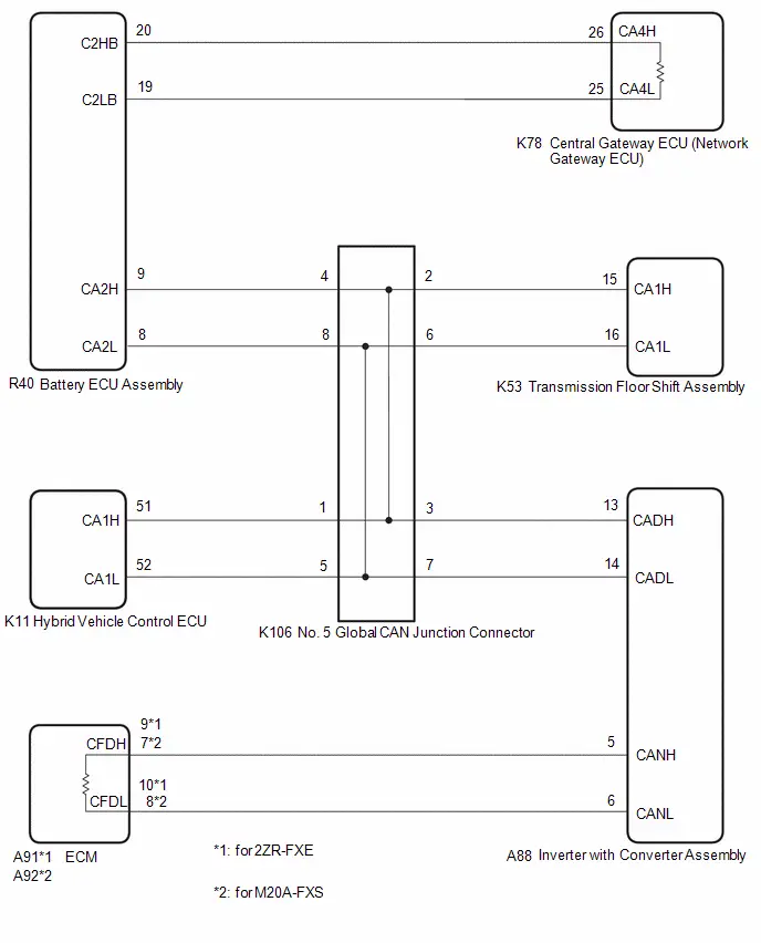
CAUTION / NOTICE / HINT
CAUTION:
When performing the confirmation driving pattern, obey all speed limits and traffic laws.
NOTICE:
-
Because the order of diagnosis is important to allow correct diagnosis, make sure to begin troubleshooting using How to Proceed with Troubleshooting when CAN communication system related DTCs are output.
Click here

- Before measuring the resistance of the CAN bus, turn the ignition switch off and leave the Toyota Prius vehicle for 1 minute or more without operating the key or any switches, or opening or closing the doors. After that, disconnect the cable from the negative (-) auxiliary battery terminal and leave the vehicle for 1 minute or more before measuring the resistance.
-
After the ignition switch is turned off, there may be a waiting time before disconnecting the negative (-) auxiliary battery terminal.
Click here

-
When disconnecting and reconnecting the auxiliary battery.
HINT:
When disconnecting and reconnecting the auxiliary battery, there is an automatic learning function that completes learning when the respective system is used.
Click here


-
Some parts must be initialized and set when replacing or removing and installing parts.
Click here


-
After performing repairs, perform the DTC check procedure and confirm that the DTCs are not output again.
DTC check procedure: Turn the ignition switch to ON and wait for 1 minute or more. Then operate the suspected malfunctioning system and drive the Toyota Prius vehicle at 60 km/h (37 mph) or more for 5 minutes or more.
-
After the repair, perform the CAN bus check and check that all the ECUs and sensors connected to the CAN communication system are displayed as normal.
Click here

-
Before replacing the hybrid Toyota Prius vehicle control ECU, refer to Registration.
Click here

- When disconnecting a wire harness of any component connected to the supply power of the integrated capacitor (integration control supply) or when removing the integrated capacitor (integration control supply), make sure to wait 5 minutes or more after turning the ignition switch off for self-diagnosis to complete and the voltage of the integrated capacitor (integration control supply) to discharge.
HINT:
- Before disconnecting related connectors for inspection, push in on each connector body to check that the connector is not loose or disconnected.
- When a connector is disconnected, check that the terminals and connector body are not cracked, deformed or corroded.
PROCEDURE
| 1. | CHECK FOR OPEN IN CAN MAIN BUS LINES |
(a) Disconnect the cable from the negative (-) auxiliary battery terminal.
| (b) Measure the resistance according to the value(s) in the table below. Standard Resistance:  Click Location & Routing(K78) Click Connector(K78) Click Location & Routing(K78) Click Connector(K78)
|
|

| NG |

| GO TO STEP 41 |
|

| 2. | CHECK FOR SHORT IN CAN BUS LINES |
| (a) Measure the resistance according to the value(s) in the table below. Standard Resistance:  Click Location & Routing(K78) Click Connector(K78) Click Location & Routing(K78) Click Connector(K78)
|
|
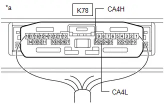
| NG |

| GO TO STEP 29 |
|

| 3. | CHECK FOR SHORT TO B IN CAN BUS LINE |
(a) Measure the resistance according to the value(s) in the table below.
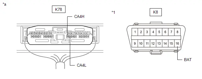
| *1 | DLC3 | - | - |
| *a | Component with harness connected (Central Gateway ECU (Network Gateway ECU)) | - | - |
Standard Resistance:
 Click Location & Routing(K78,K8) Click Connector(K78) Click Connector(K8)
 | Tester Connection | Condition | Specified Condition |
|---|---|---|
| K78-26 (CA4H) - K8-16 (BAT) | Cable disconnected from negative (-) auxiliary battery terminal | 6 kΩ or higher |
| K78-25 (CA4L) - K8-16 (BAT) |
| NG |

| GO TO STEP 17 |
|

| 4. | CHECK FOR SHORT TO GND IN CAN BUS LINE |
(a) Measure the resistance according to the value(s) in the table below.
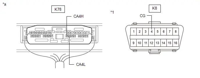
| *1 | DLC3 | - | - |
| *a | Component with harness connected (Central Gateway ECU (Network Gateway ECU)) | - | - |
Standard Resistance:
 Click Location & Routing(K78,K8) Click Connector(K78) Click Connector(K8)
 | Tester Connection | Condition | Specified Condition |
|---|---|---|
| K78-26 (CA4H) - K8-4 (CG) | Cable disconnected from negative (-) auxiliary battery terminal | 200 Ω or higher |
| K78-25 (CA4L) - K8-4 (CG) |
| OK |

| REPLACE CENTRAL GATEWAY ECU (NETWORK GATEWAY ECU) |
|

| 5. | CHECK FOR SHORT TO GND IN CAN BUS LINE (BATTERY ECU ASSEMBLY - CENTRAL GATEWAY ECU (NETWORK GATEWAY ECU)) |
(a) Disconnect the R40 battery ECU assembly connector.
(b) Measure the resistance according to the value(s) in the table below.
Standard Resistance:
 Click Location & Routing(R40,K8) Click Connector(R40) Click Connector(K8)
 | Tester Connection | Condition | Specified Condition |
|---|---|---|
| R40-20 (C2HB) - K8-4 (CG) | Cable disconnected from negative (-) auxiliary battery terminal | 200 Ω or higher |
| R40-19 (C2LB) - K8-4 (CG) |
| NG |

| GO TO STEP 7 |
|

| 6. | CHECK FOR SHORT TO GND IN CAN BUS LINE (BATTERY ECU ASSEMBLY - NO. 5 GLOBAL CAN JUNCTION CONNECTOR) |
(a) Measure the resistance according to the value(s) in the table below.
Standard Resistance:
 Click Location & Routing(R40,K8) Click Connector(R40) Click Connector(K8)
 | Tester Connection | Condition | Specified Condition |
|---|---|---|
| R40-9 (CA2H) - K8-4 (CG) | Cable disconnected from negative (-) auxiliary battery terminal | 200 Ω or higher |
| R40-8 (CA2L) - K8-4 (CG) |
| OK |

| REPLACE BATTERY ECU ASSEMBLY |
| NG |

| GO TO STEP 8 |
| 7. | CHECK FOR SHORT TO GND IN CAN BUS LINE (BATTERY ECU ASSEMBLY - CENTRAL GATEWAY ECU (NETWORK GATEWAY ECU)) |
(a) Disconnect the K78 central gateway ECU (network gateway ECU) connector.
(b) Measure the resistance according to the value(s) in the table below.
Standard Resistance:
 Click Location & Routing(R40,K8) Click Connector(R40) Click Connector(K8)
 | Tester Connection | Condition | Specified Condition |
|---|---|---|
| R40-20 (C2HB) - K8-4 (CG) | Cable disconnected from negative (-) auxiliary battery terminal | 200 Ω or higher |
| R40-19 (C2LB) - K8-4 (CG) |
| OK |

| REPLACE CENTRAL GATEWAY ECU (NETWORK GATEWAY ECU) |
| NG |

| REPAIR OR REPLACE CAN MAIN BUS LINE OR CONNECTOR (BATTERY ECU ASSEMBLY - CENTRAL GATEWAY ECU (NETWORK GATEWAY ECU)) |
| 8. | CHECK FOR SHORT TO GND IN CAN BUS LINE (NO. 5 GLOBAL CAN JUNCTION CONNECTOR - BATTERY ECU ASSEMBLY) |
(a) Disconnect the K106 No. 5 global CAN junction connector.
(b) Measure the resistance according to the value(s) in the table below.
Standard Resistance:
 Click Location & Routing(K106,K8) Click Connector(K106) Click Connector(K8)
 | Tester Connection | Condition | Specified Condition |
|---|---|---|
| K106-4 (CANH) - K8-4 (CG) | Cable disconnected from negative (-) auxiliary battery terminal | 200 Ω or higher |
| K106-8 (CANL) - K8-4 (CG) |
| NG |

| REPAIR OR REPLACE CAN MAIN BUS LINE OR CONNECTOR (NO. 5 GLOBAL CAN JUNCTION CONNECTOR - BATTERY ECU ASSEMBLY) |
|

| 9. | CHECK FOR SHORT TO GND IN CAN BUS LINE (NO. 5 GLOBAL CAN JUNCTION CONNECTOR - INVERTER WITH CONVERTER ASSEMBLY) |
(a) Measure the resistance according to the value(s) in the table below.
Standard Resistance:
 Click Location & Routing(K106,K8) Click Connector(K106) Click Connector(K8)
 | Tester Connection | Condition | Specified Condition |
|---|---|---|
| K106-3 (CANH) - K8-4 (CG) | Cable disconnected from negative (-) auxiliary battery terminal | 200 Ω or higher |
| K106-7 (CANL) - K8-4 (CG) |
| NG |

| GO TO STEP 14 |
|

| 10. | CHECK FOR SHORT TO GND IN CAN BUS LINE (NO. 5 GLOBAL CAN JUNCTION CONNECTOR - HYBRID Toyota Prius Vehicle CONTROL ECU) |
(a) Measure the resistance according to the value(s) in the table below.
Standard Resistance:
 Click Location & Routing(K106,K8) Click Connector(K106) Click Connector(K8)
 | Tester Connection | Condition | Specified Condition |
|---|---|---|
| K106-1 (CANH) - K8-4 (CG) | Cable disconnected from negative (-) auxiliary battery terminal | 200 Ω or higher |
| K106-5 (CANL) - K8-4 (CG) |
| NG |

| GO TO STEP 12 |
|

| 11. | CHECK FOR SHORT TO GND IN CAN BUS LINE (NO. 5 GLOBAL CAN JUNCTION CONNECTOR - TRANSMISSION FLOOR SHIFT ASSEMBLY) |
(a) Measure the resistance according to the value(s) in the table below.
Standard Resistance:
 Click Location & Routing(K106,K8) Click Connector(K106) Click Connector(K8)
 | Tester Connection | Condition | Specified Condition |
|---|---|---|
| K106-2 (CANH) - K8-4 (CG) | Cable disconnected from negative (-) auxiliary battery terminal | 200 Ω or higher |
| K106-6 (CANL) - K8-4 (CG) |
| OK |

| REPLACE NO. 5 GLOBAL CAN JUNCTION CONNECTOR |
| NG |

| GO TO STEP 13 |
| 12. | CHECK FOR SHORT TO GND IN CAN BUS LINE (NO. 5 GLOBAL CAN JUNCTION CONNECTOR - HYBRID Toyota Prius Vehicle CONTROL ECU) |
(a) Disconnect the K11 hybrid vehicle control ECU connector.
(b) Measure the resistance according to the value(s) in the table below.
Standard Resistance:
 Click Location & Routing(K106,K8) Click Connector(K106) Click Connector(K8)
 | Tester Connection | Condition | Specified Condition |
|---|---|---|
| K106-1 (CANH) - K8-4 (CG) | Cable disconnected from negative (-) auxiliary battery terminal | 200 Ω or higher |
| K106-5 (CANL) - K8-4 (CG) |
| OK |

| REPLACE HYBRID Toyota Prius Vehicle CONTROL ECU
|


| NG |

| REPAIR OR REPLACE CAN BRANCH LINE OR CONNECTOR (NO. 5 GLOBAL CAN JUNCTION CONNECTOR - HYBRID Toyota Prius Vehicle CONTROL ECU) |
| 13. | CHECK FOR SHORT TO GND IN CAN BUS LINE (NO. 5 GLOBAL CAN JUNCTION CONNECTOR - TRANSMISSION FLOOR SHIFT ASSEMBLY) |
(a) Disconnect the K53 transmission floor shift assembly connector.
(b) Measure the resistance according to the value(s) in the table below.
Standard Resistance:
 Click Location & Routing(K106,K8) Click Connector(K106) Click Connector(K8)
 | Tester Connection | Condition | Specified Condition |
|---|---|---|
| K106-2 (CANH) - K8-4 (CG) | Cable disconnected from negative (-) auxiliary battery terminal | 200 Ω or higher |
| K106-6 (CANL) - K8-4 (CG) |
| OK |

| REPLACE TRANSMISSION FLOOR SHIFT ASSEMBLY |
| NG |

| REPAIR OR REPLACE CAN BRANCH LINE OR CONNECTOR (NO. 5 GLOBAL CAN JUNCTION CONNECTOR - TRANSMISSION FLOOR SHIFT ASSEMBLY) |
| 14. | CHECK FOR SHORT TO GND IN CAN BUS LINE (INVERTER WITH CONVERTER ASSEMBLY - NO. 5 GLOBAL CAN JUNCTION CONNECTOR) |
(a) Disconnect the A88 inverter with converter assembly connector.
(b) Measure the resistance according to the value(s) in the table below.
Standard Resistance:
 Click Location & Routing(A88,K8) Click Connector(A88) Click Connector(K8)
 | Tester Connection | Condition | Specified Condition |
|---|---|---|
| A88-13 (CADH) - K8-4 (CG) | Cable disconnected from negative (-) auxiliary battery terminal | 200 Ω or higher |
| A88-14 (CADL) - K8-4 (CG) |
| NG |

| REPAIR OR REPLACE CAN MAIN BUS LINE OR CONNECTOR (INVERTER WITH CONVERTER ASSEMBLY - NO. 5 GLOBAL CAN JUNCTION CONNECTOR) |
|

| 15. | CHECK FOR SHORT TO GND IN CAN BUS LINE (INVERTER WITH CONVERTER ASSEMBLY - ECM) |
(a) Measure the resistance according to the value(s) in the table below.
Standard Resistance:
 Click Location & Routing(A88,K8) Click Connector(A88) Click Connector(K8)
 | Tester Connection | Condition | Specified Condition |
|---|---|---|
| A88-5 (CANH) - K8-4 (CG) | Cable disconnected from negative (-) auxiliary battery terminal | 200 Ω or higher |
| A88-6 (CANL) - K8-4 (CG) |
| OK |

| REPLACE INVERTER WITH CONVERTER ASSEMBLY |
|

| 16. | CHECK FOR SHORT TO GND IN CAN BUS LINE (INVERTER WITH CONVERTER ASSEMBLY - ECM) |
(a) Disconnect the A91 or A92 ECM connector.
(b) Measure the resistance according to the value(s) in the table below.
Standard Resistance:
 Click Location & Routing(A88,K8) Click Connector(A88) Click Connector(K8)
 | Tester Connection | Condition | Specified Condition |
|---|---|---|
| A88-5 (CANH) - K8-4 (CG) | Cable disconnected from negative (-) auxiliary battery terminal | 200 Ω or higher |
| A88-6 (CANL) - K8-4 (CG) |
| OK |

| REPLACE ECM
|


| NG |

| REPAIR OR REPLACE CAN MAIN BUS LINE OR CONNECTOR (INVERTER WITH CONVERTER ASSEMBLY - ECM) |
| 17. | CHECK FOR SHORT TO B IN CAN BUS LINE (BATTERY ECU ASSEMBLY - CENTRAL GATEWAY ECU (NETWORK GATEWAY ECU)) |
(a) Disconnect the R40 battery ECU assembly connector.
(b) Measure the resistance according to the value(s) in the table below.
Standard Resistance:
 Click Location & Routing(R40,K8) Click Connector(R40) Click Connector(K8)
 | Tester Connection | Condition | Specified Condition |
|---|---|---|
| R40-20 (C2HB ) - K8-16 (BAT) | Cable disconnected from negative (-) auxiliary battery terminal | 6 kΩ or higher |
| R40-19 (C2LB) - K8-16 (BAT) |
| NG |

| GO TO STEP 19 |
|

| 18. | CHECK FOR SHORT TO B IN CAN BUS LINE (BATTERY ECU ASSEMBLY - NO. 5 GLOBAL CAN JUNCTION CONNECTOR) |
(a) Measure the resistance according to the value(s) in the table below.
Standard Resistance:
 Click Location & Routing(R40,K8) Click Connector(R40) Click Connector(K8)
 | Tester Connection | Condition | Specified Condition |
|---|---|---|
| R40-9 (CA2H) - K8-16 (BAT) | Cable disconnected from negative (-) auxiliary battery terminal | 6 kΩ or higher |
| R40-8 (CA2L) - K8-16 (BAT) |
| OK |

| REPLACE BATTERY ECU ASSEMBLY |
| NG |

| GO TO STEP 20 |
| 19. | CHECK FOR SHORT TO B IN CAN BUS LINE (BATTERY ECU ASSEMBLY - CENTRAL GATEWAY ECU (NETWORK GATEWAY ECU)) |
(a) Disconnect the K78 central gateway ECU (network gateway ECU) connector.
(b) Measure the resistance according to the value(s) in the table below.
Standard Resistance:
 Click Location & Routing(R40,K8) Click Connector(R40) Click Connector(K8)
 | Tester Connection | Condition | Specified Condition |
|---|---|---|
| R40-20 (C2HB ) - K8-16 (BAT) | Cable disconnected from negative (-) auxiliary battery terminal | 6 kΩ or higher |
| R40-19 (C2LB) - K8-16 (BAT) |
| OK |

| REPLACE CENTRAL GATEWAY ECU (NETWORK GATEWAY ECU) |
| NG |

| REPAIR OR REPLACE CAN MAIN BUS LINE OR CONNECTOR (BATTERY ECU ASSEMBLY - CENTRAL GATEWAY ECU (NETWORK GATEWAY ECU)) |
| 20. | CHECK FOR SHORT TO B IN CAN BUS LINE (NO. 5 GLOBAL CAN JUNCTION CONNECTOR - BATTERY ECU ASSEMBLY) |
(a) Disconnect the K106 No. 5 global CAN junction connector.
(b) Measure the resistance according to the value(s) in the table below.
Standard Resistance:
 Click Location & Routing(K106,K8) Click Connector(K106) Click Connector(K8)
 | Tester Connection | Condition | Specified Condition |
|---|---|---|
| K106-4 (CANH) - K8-16 (BAT) | Cable disconnected from negative (-) auxiliary battery terminal | 6 kΩ or higher |
| K106-8 (CANL) - K8-16 (BAT) |
| NG |

| REPAIR OR REPLACE CAN MAIN BUS LINE OR CONNECTOR (NO. 5 GLOBAL CAN JUNCTION CONNECTOR - BATTERY ECU ASSEMBLY) |
|

| 21. | CHECK FOR SHORT TO B IN CAN BUS LINE (NO. 5 GLOBAL CAN JUNCTION CONNECTOR - INVERTER WITH CONVERTER ASSEMBLY) |
(a) Measure the resistance according to the value(s) in the table below.
Standard Resistance:
 Click Location & Routing(K106,K8) Click Connector(K106) Click Connector(K8)
 | Tester Connection | Condition | Specified Condition |
|---|---|---|
| K106-3 (CANH) - K8-16 (BAT) | Cable disconnected from negative (-) auxiliary battery terminal | 6 kΩ or higher |
| K106-7 (CANL) - K8-16 (BAT) |
| NG |

| GO TO STEP 26 |
|

| 22. | CHECK FOR SHORT TO B IN CAN BUS LINE (NO. 5 GLOBAL CAN JUNCTION CONNECTOR - HYBRID Toyota Prius Vehicle CONTROL ECU) |
(a) Measure the resistance according to the value(s) in the table below.
Standard Resistance:
 Click Location & Routing(K106,K8) Click Connector(K106) Click Connector(K8)
 | Tester Connection | Condition | Specified Condition |
|---|---|---|
| K106-1 (CANH) - K8-16 (BAT) | Cable disconnected from negative (-) auxiliary battery terminal | 6 kΩ or higher |
| K106-5 (CANL) - K8-16 (BAT) |
| NG |

| GO TO STEP 24 |
|

| 23. | CHECK FOR SHORT TO B IN CAN BUS LINE (NO. 5 GLOBAL CAN JUNCTION CONNECTOR - TRANSMISSION FLOOR SHIFT ASSEMBLY) |
(a) Measure the resistance according to the value(s) in the table below.
Standard Resistance:
 Click Location & Routing(K106,K8) Click Connector(K106) Click Connector(K8)
 | Tester Connection | Condition | Specified Condition |
|---|---|---|
| K106-2 (CANH) - K8-16 (BAT) | Cable disconnected from negative (-) auxiliary battery terminal | 6 kΩ or higher |
| K106-6 (CANL) - K8-16 (BAT) |
| OK |

| REPLACE NO. 5 GLOBAL CAN JUNCTION CONNECTOR |
| NG |

| GO TO STEP 25 |
| 24. | CHECK FOR SHORT TO B IN CAN BUS LINE (NO. 5 GLOBAL CAN JUNCTION CONNECTOR - HYBRID Toyota Prius Vehicle CONTROL ECU) |
(a) Disconnect the K11 hybrid vehicle control ECU connector.
(b) Measure the resistance according to the value(s) in the table below.
Standard Resistance:
 Click Location & Routing(K106,K8) Click Connector(K106) Click Connector(K8)
 | Tester Connection | Condition | Specified Condition |
|---|---|---|
| K106-1 (CANH) - K8-16 (BAT) | Cable disconnected from negative (-) auxiliary battery terminal | 6 kΩ or higher |
| K106-5 (CANL) - K8-16 (BAT) |
| OK |

| REPLACE HYBRID Toyota Prius Vehicle CONTROL ECU
|


| NG |

| REPAIR OR REPLACE CAN BRANCH LINE OR CONNECTOR (NO. 5 GLOBAL CAN JUNCTION CONNECTOR - HYBRID Toyota Prius Vehicle CONTROL ECU) |
| 25. | CHECK FOR SHORT TO B IN CAN BUS LINE (NO. 5 GLOBAL CAN JUNCTION CONNECTOR - TRANSMISSION FLOOR SHIFT ASSEMBLY) |
(a) Disconnect the K53 transmission floor shift assembly connector.
(b) Measure the resistance according to the value(s) in the table below.
Standard Resistance:
 Click Location & Routing(K106,K8) Click Connector(K106) Click Connector(K8)
 | Tester Connection | Condition | Specified Condition |
|---|---|---|
| K106-2 (CANH) - K8-16 (BAT) | Cable disconnected from negative (-) auxiliary battery terminal | 6 kΩ or higher |
| K106-6 (CANL) - K8-16 (BAT) |
| OK |

| REPLACE TRANSMISSION FLOOR SHIFT ASSEMBLY |
| NG |

| REPAIR OR REPLACE CAN BRANCH LINE OR CONNECTOR (NO. 5 GLOBAL CAN JUNCTION CONNECTOR - TRANSMISSION FLOOR SHIFT ASSEMBLY) |
| 26. | CHECK FOR SHORT TO B IN CAN BUS LINE (INVERTER WITH CONVERTER ASSEMBLY - NO. 5 GLOBAL CAN JUNCTION CONNECTOR) |
(a) Disconnect the A88 inverter with converter assembly connector.
(b) Measure the resistance according to the value(s) in the table below.
Standard Resistance:
 Click Location & Routing(A88,K8) Click Connector(A88) Click Connector(K8)
 | Tester Connection | Condition | Specified Condition |
|---|---|---|
| A88-13 (CADH) - K8-16 (BAT) | Cable disconnected from negative (-) auxiliary battery terminal | 6 kΩ or higher |
| A88-14 (CADL) - K8-16 (BAT) |
| NG |

| REPAIR OR REPLACE CAN MAIN BUS LINE OR CONNECTOR (INVERTER WITH CONVERTER ASSEMBLY - NO. 5 GLOBAL CAN JUNCTION CONNECTOR) |
|

| 27. | CHECK FOR SHORT TO B IN CAN BUS LINE (INVERTER WITH CONVERTER ASSEMBLY - ECM) |
(a) Measure the resistance according to the value(s) in the table below.
Standard Resistance:
 Click Location & Routing(A88,K8) Click Connector(A88) Click Connector(K8)
 | Tester Connection | Condition | Specified Condition |
|---|---|---|
| A88-5 (CANH) - K8-16 (BAT) | Cable disconnected from negative (-) auxiliary battery terminal | 6 kΩ or higher |
| A88-6 (CANL) - K8-16 (BAT) |
| OK |

| REPLACE INVERTER WITH CONVERTER ASSEMBLY |
|

| 28. | CHECK FOR SHORT TO B IN CAN BUS LINE (INVERTER WITH CONVERTER ASSEMBLY - ECM) |
(a) Disconnect the A91 or A92 ECM connector.
(b) Measure the resistance according to the value(s) in the table below.
Standard Resistance:
 Click Location & Routing(A88,K8) Click Connector(A88) Click Connector(K8)
 | Tester Connection | Condition | Specified Condition |
|---|---|---|
| A88-5 (CANH) - K8-6 (BAT) | Cable disconnected from negative (-) auxiliary battery terminal | 6 kΩ or higher |
| A88-6 (CANL) - K8-6 (BAT) |
| OK |

| REPLACE ECM
|


| NG |

| REPAIR OR REPLACE CAN MAIN BUS LINE OR CONNECTOR (INVERTER WITH CONVERTER ASSEMBLY - ECM) |
| 29. | CHECK FOR SHORT IN CAN BUS LINES (BATTERY ECU ASSEMBLY - CENTRAL GATEWAY ECU (NETWORK GATEWAY ECU)) |
(a) Disconnect the R40 battery ECU assembly connector.
(b) Measure the resistance according to the value(s) in the table below.
Standard Resistance:
 Click Location & Routing(R40) Click Connector(R40)
 | Tester Connection | Condition | Specified Condition |
|---|---|---|
| R40-20 (C2HB) - R40-19 (C2LB) | Cable disconnected from negative (-) auxiliary battery terminal | 108 to 132 Ω |
| NG |

| GO TO STEP 31 |
|

| 30. | CHECK FOR SHORT IN CAN BUS LINES (BATTERY ECU ASSEMBLY - NO. 5 GLOBAL CAN JUNCTION CONNECTOR) |
(a) Measure the resistance according to the value(s) in the table below.
Standard Resistance:
 Click Location & Routing(R40) Click Connector(R40)
 | Tester Connection | Condition | Specified Condition |
|---|---|---|
| R40-9 (CA2H) - R40-8 (CA2L) | Cable disconnected from negative (-) auxiliary battery terminal | 108 to 132 Ω |
| OK |

| REPLACE BATTERY ECU ASSEMBLY |
| NG |

| GO TO STEP 32 |
| 31. | CHECK FOR SHORT IN CAN BUS LINES (BATTERY ECU ASSEMBLY - CENTRAL GATEWAY ECU (NETWORK GATEWAY ECU)) |
(a) Disconnect the K78 central gateway ECU (network gateway ECU) connector.
(b) Measure the resistance according to the value(s) in the table below.
Standard Resistance:
 Click Location & Routing(R40) Click Connector(R40)
 | Tester Connection | Condition | Specified Condition |
|---|---|---|
| R40-20 (C2HB) - R40-19 (C2LB) | Cable disconnected from negative (-) auxiliary battery terminal | 1 MΩ or higher |
| OK |

| REPLACE CENTRAL GATEWAY ECU (NETWORK GATEWAY ECU) |
| NG |

| REPAIR OR REPLACE CAN MAIN BUS LINES OR CONNECTOR (BATTERY ECU ASSEMBLY - CENTRAL GATEWAY ECU (NETWORK GATEWAY ECU)) |
| 32. | CHECK FOR SHORT IN CAN BUS LINES (NO. 5 GLOBAL CAN JUNCTION CONNECTOR - BATTERY ECU ASSEMBLY) |
(a) Reconnect the R40 battery ECU assembly connector.
(b) Disconnect the K106 No. 5 global CAN junction connector.
(c) Measure the resistance according to the value(s) in the table below.
Standard Resistance:
 Click Location & Routing(K106) Click Connector(K106)
 | Tester Connection | Condition | Specified Condition |
|---|---|---|
| K106-4 (CANH) - K106-8 (CANL) | Cable disconnected from negative (-) auxiliary battery terminal | 108 to 132 Ω |
| NG |

| REPAIR OR REPLACE CAN MAIN BUS LINES OR CONNECTOR (NO. 5 GLOBAL CAN JUNCTION CONNECTOR - BATTERY ECU ASSEMBLY) |
|

| 33. | CHECK FOR SHORT IN CAN BUS LINES (NO. 5 GLOBAL CAN JUNCTION CONNECTOR - INVERTER WITH CONVERTER ASSEMBLY) |
(a) Measure the resistance according to the value(s) in the table below.
Standard Resistance:
 Click Location & Routing(K106) Click Connector(K106)
 | Tester Connection | Condition | Specified Condition |
|---|---|---|
| K106-3 (CANH) - K106-7 (CANL) | Cable disconnected from negative (-) auxiliary battery terminal | 108 to 132 Ω |
| NG |

| GO TO STEP 38 |
|

| 34. | CHECK FOR SHORT IN CAN BUS LINES (NO. 5 GLOBAL CAN JUNCTION CONNECTOR - HYBRID Toyota Prius Vehicle CONTROL ECU) |
(a) Measure the resistance according to the value(s) in the table below.
Standard Resistance:
 Click Location & Routing(K106) Click Connector(K106)
 | Tester Connection | Condition | Specified Condition |
|---|---|---|
| K106-1 (CANH) - K106-5 (CANL) | Cable disconnected from negative (-) auxiliary battery terminal | 200 Ω or higher |
| NG |

| GO TO STEP 36 |
|

| 35. | CHECK FOR SHORT IN CAN BUS LINES (NO. 5 GLOBAL CAN JUNCTION CONNECTOR - TRANSMISSION FLOOR SHIFT ASSEMBLY) |
(a) Measure the resistance according to the value(s) in the table below.
Standard Resistance:
 Click Location & Routing(K106) Click Connector(K106)
 | Tester Connection | Condition | Specified Condition |
|---|---|---|
| K106-2 (CANH) - K106-6 (CANL) | Cable disconnected from negative (-) auxiliary battery terminal | 200 Ω or higher |
| OK |

| REPLACE NO. 5 GLOBAL CAN JUNCTION CONNECTOR |
| NG |

| GO TO STEP 37 |
| 36. | CHECK FOR SHORT IN CAN BUS LINES (NO. 5 GLOBAL CAN JUNCTION CONNECTOR - HYBRID Toyota Prius Vehicle CONTROL ECU) |
(a) Disconnect the K11 hybrid vehicle control ECU connector.
(b) Measure the resistance according to the value(s) in the table below.
Standard Resistance:
 Click Location & Routing(K106) Click Connector(K106)
 | Tester Connection | Condition | Specified Condition |
|---|---|---|
| K106-1 (CANH) - K106-5 (CANL) | Cable disconnected from negative (-) auxiliary battery terminal | 1 MΩ or higher |
| OK |

| REPLACE HYBRID Toyota Prius Vehicle CONTROL ECU
|


| NG |

| REPAIR OR REPLACE CAN BRANCH LINE OR CONNECTOR (NO. 5 GLOBAL CAN JUNCTION CONNECTOR - HYBRID Toyota Prius Vehicle CONTROL ECU) |
| 37. | CHECK FOR SHORT IN CAN BUS LINES (NO. 5 GLOBAL CAN JUNCTION CONNECTOR - TRANSMISSION FLOOR SHIFT ASSEMBLY) |
(a) Disconnect the K53 transmission floor shift assembly connector.
(b) Measure the resistance according to the value(s) in the table below.
Standard Resistance:
 Click Location & Routing(K106) Click Connector(K106)
 | Tester Connection | Condition | Specified Condition |
|---|---|---|
| K106-2 (CANH) - K106-6 (CANL) | Cable disconnected from negative (-) auxiliary battery terminal | 1 MΩ or higher |
| OK |

| REPLACE TRANSMISSION FLOOR SHIFT ASSEMBLY |
| NG |

| REPAIR OR REPLACE CAN BRANCH LINES OR CONNECTOR (NO. 5 GLOBAL CAN JUNCTION CONNECTOR - TRANSMISSION FLOOR SHIFT ASSEMBLY) |
| 38. | CHECK FOR SHORT IN CAN BUS LINES (INVERTER WITH CONVERTER ASSEMBLY - NO. 5 GLOBAL CAN JUNCTION CONNECTOR) |
(a) Reconnect the K106 No. 5 global CAN junction connector.
(b) Disconnect the A88 inverter with converter assembly connector.
(c) Measure the resistance according to the value(s) in the table below.
Standard Resistance:
 Click Location & Routing(A88) Click Connector(A88)
 | Tester Connection | Condition | Specified Condition |
|---|---|---|
| A88-13 (CADH) - A88-14 (CADL) | Cable disconnected from negative (-) auxiliary battery terminal | 108 to 132 Ω |
| NG |

| REPAIR OR REPLACE CAN MAIN BUS LINES OR CONNECTOR (INVERTER WITH CONVERTER ASSEMBLY - NO. 5 GLOBAL CAN JUNCTION CONNECTOR) |
|

| 39. | CHECK FOR SHORT IN CAN BUS LINES (INVERTER WITH CONVERTER ASSEMBLY - ECM) |
(a) Measure the resistance according to the value(s) in the table below.
Standard Resistance:
 Click Location & Routing(A88) Click Connector(A88)
 | Tester Connection | Condition | Specified Condition |
|---|---|---|
| A88-5 (CANH) - A88-6 (CANL) | Cable disconnected from negative (-) auxiliary battery terminal | 108 to 132 Ω |
| OK |

| REPLACE INVERTER WITH CONVERTER ASSEMBLY |
|

| 40. | CHECK FOR SHORT IN CAN BUS LINES (INVERTER WITH CONVERTER ASSEMBLY - ECM) |
(a) Disconnect the A91 or A92 ECM connector.
(b) Measure the resistance according to the value(s) in the table below.
Standard Resistance:
 Click Location & Routing(A88) Click Connector(A88)
 | Tester Connection | Condition | Specified Condition |
|---|---|---|
| A88-5 (CANH) - A88-6 (CANL) | Cable disconnected from negative (-) auxiliary battery terminal | 1 MΩ or higher |
| OK |

| REPLACE ECM
|


| NG |

| REPAIR OR REPLACE CAN MAIN BUS LINES OR CONNECTOR (INVERTER WITH CONVERTER ASSEMBLY - ECM) |
| 41. | CHECK FOR OPEN IN CAN MAIN BUS LINES (CENTRAL GATEWAY ECU (NETWORK GATEWAY ECU)) |
(a) Disconnect the K78 central gateway ECU (network gateway ECU) connector.
(b) Measure the resistance according to the value(s) in the table below.
Standard Resistance:
 Click Location & Routing(K78) Click Connector(K78)
 | Tester Connection | Condition | Specified Condition |
|---|---|---|
| K78-26 (CA4H) - K78-25 (CA4L) | Cable disconnected from negative (-) auxiliary battery terminal | 108 to 132 Ω |
| OK |

| REPLACE CENTRAL GATEWAY ECU (NETWORK GATEWAY ECU) |
|

| 42. | CHECK FOR OPEN IN CAN MAIN BUS LINES (BATTERY ECU ASSEMBLY - CENTRAL GATEWAY ECU (NETWORK GATEWAY ECU)) |
(a) Reconnect the K78 central gateway ECU (network gateway ECU) connector.
(b) Disconnect the R40 battery ECU assembly connector.
(c) Measure the resistance according to the value(s) in the table below.
Standard Resistance:
 Click Location & Routing(R40) Click Connector(R40)
 | Tester Connection | Condition | Specified Condition |
|---|---|---|
| R40-20 (C2HB) - R40-19 (C2LB) | Cable disconnected from negative (-) auxiliary battery terminal | 108 to 132 Ω |
| NG |

| REPAIR OR REPLACE CAN MAIN BUS LINES OR CONNECTOR (BATTERY ECU ASSEMBLY - CENTRAL GATEWAY ECU (NETWORK GATEWAY ECU)) |
|

| 43. | CHECK FOR OPEN IN CAN MAIN BUS LINES (BATTERY ECU ASSEMBLY - NO. 5 GLOBAL CAN JUNCTION CONNECTOR) |
(a) Measure the resistance according to the value(s) in the table below.
Standard Resistance:
 Click Location & Routing(R40) Click Connector(R40)
 | Tester Connection | Condition | Specified Condition |
|---|---|---|
| R40-9 (CA2H) - R40-8 (CA2L) | Cable disconnected from negative (-) auxiliary battery terminal | 108 to 132 Ω |
| OK |

| REPLACE BATTERY ECU ASSEMBLY |
|

| 44. | CHECK FOR OPEN IN CAN MAIN BUS LINES (NO. 5 GLOBAL CAN JUNCTION CONNECTOR - BATTERY ECU ASSEMBLY) |
(a) Reconnect the R40 battery ECU assembly connector.
(b) Disconnect the K106 No. 5 global CAN junction connector.
(c) Measure the resistance according to the value(s) in the table below.
Standard Resistance:
 Click Location & Routing(K106) Click Connector(K106)
 | Tester Connection | Condition | Specified Condition |
|---|---|---|
| K106-4 (CANH) - K106-8 (CANL) | Cable disconnected from negative (-) auxiliary battery terminal | 108 to 132 Ω |
| NG |

| REPAIR OR REPLACE CAN MAIN BUS LINES OR CONNECTOR (NO. 5 GLOBAL CAN JUNCTION CONNECTOR - BATTERY ECU ASSEMBLY) |
|

| 45. | CHECK FOR OPEN IN CAN MAIN BUS LINES (NO. 5 GLOBAL CAN JUNCTION CONNECTOR - INVERTER WITH CONVERTER ASSEMBLY) |
(a) Measure the resistance according to the value(s) in the table below.
Standard Resistance:
 Click Location & Routing(K106) Click Connector(K106)
 | Tester Connection | Condition | Specified Condition |
|---|---|---|
| K106-3 (CANH) - K106-7 (CANL) | Cable disconnected from negative (-) auxiliary battery terminal | 108 to 132 Ω |
| OK |

| REPLACE NO. 5 GLOBAL CAN JUNCTION CONNECTOR |
|

| 46. | CHECK FOR OPEN IN CAN MAIN BUS LINES (INVERTER WITH CONVERTER ASSEMBLY - NO. 5 GLOBAL CAN JUNCTION CONNECTOR) |
(a) Reconnect the K106 No. 5 global CAN junction connector.
(b) Disconnect the A88 inverter with converter assembly connector.
(c) Measure the resistance according to the value(s) in the table below.
Standard Resistance:
 Click Location & Routing(A88) Click Connector(A88)
 | Tester Connection | Condition | Specified Condition |
|---|---|---|
| A88-13 (CADH) - A88-14 (CADL) | Cable disconnected from negative (-) auxiliary battery terminal | 108 to 132 Ω |
| NG |

| REPAIR OR REPLACE CAN MAIN BUS LINES OR CONNECTOR (INVERTER WITH CONVERTER ASSEMBLY - NO. 5 GLOBAL CAN JUNCTION CONNECTOR) |
|

| 47. | CHECK FOR OPEN IN CAN MAIN BUS LINES (INVERTER WITH CONVERTER ASSEMBLY - ECM) |
(a) Measure the resistance according to the value(s) in the table below.
Standard Resistance:
 Click Location & Routing(A88) Click Connector(A88)
 | Tester Connection | Condition | Specified Condition |
|---|---|---|
| A88-5 (CANH) - A88-6 (CANL) | Cable disconnected from negative (-) auxiliary battery terminal | 108 to 132 Ω |
| OK |

| REPLACE INVERTER WITH CONVERTER ASSEMBLY |
|

| 48. | CHECK Toyota Prius Vehicle TYPE |
(a) Check vehicle type.
| Result | Proceed to |
|---|---|
| for M20A-FXS | A |
| for 2ZR-FXE | B |
| B |

| GO TO STEP 50 |
|

| 49. | CHECK FOR OPEN IN CAN MAIN BUS LINES (ECM) |
(a) Reconnect the A88 inverter with converter assembly connector.
(b) Disconnect the A92 ECM connector.
(c) Measure the resistance according to the value(s) in the table below.
Standard Resistance:
 Click Location & Routing(A92) Click Connector(A92)
 | Tester Connection | Condition | Specified Condition |
|---|---|---|
| A92-7 (CFDH) - A92-8 (CFDL) | Cable disconnected from negative (-) auxiliary battery terminal | 108 to 132 Ω |
| OK |

| REPLACE ECM
|


| NG |

| REPAIR OR REPLACE CAN MAIN BUS LINES OR CONNECTOR (ECM - HYBRID MOTOR CONTROL INVERTER ASSEMBLY) |
| 50. | CHECK FOR OPEN IN CAN MAIN BUS LINES (ECM) |
(a) Reconnect the A88 inverter with converter assembly connector.
(b) Disconnect the A91 ECM connector.
(c) Measure the resistance according to the value(s) in the table below.
Standard Resistance:
 Click Location & Routing(A91) Click Connector(A91)
 | Tester Connection | Condition | Specified Condition |
|---|---|---|
| A91-9 (CFDH) - A91-10 (CFDL) | Cable disconnected from negative (-) auxiliary battery terminal | 108 to 132 Ω |
| OK |

| REPLACE ECM |
| NG |

| REPAIR OR REPLACE CAN MAIN BUS LINES OR CONNECTOR (ECM - HYBRID MOTOR CONTROL INVERTER ASSEMBLY) |
Check Bus 3 Line
DESCRIPTION
| Symptom | Trouble Area |
|---|---|
| There are ECUs or sensors that display a communication stop on the bus diagnostic screen. Or, there are ECUs or sensors that display communication stop history on the "Detail" screen. |
|
WIRING DIAGRAM
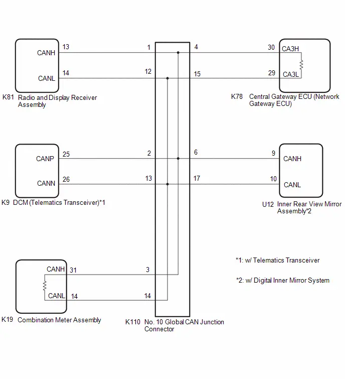
CAUTION / NOTICE / HINT
CAUTION:
When performing the confirmation driving pattern, obey all speed limits and traffic laws.
NOTICE:
-
Because the order of diagnosis is important to allow correct diagnosis, make sure to begin troubleshooting using How to Proceed with Troubleshooting when CAN communication system related DTCs are output.
Click here

- Before measuring the resistance of the CAN bus, turn the ignition switch off and leave the Toyota Prius vehicle for 1 minute or more without operating the key or any switches, or opening or closing the doors. After that, disconnect the cable from the negative (-) auxiliary battery terminal and leave the vehicle for 1 minute or more before measuring the resistance.
-
After the ignition switch is turned off, there may be a waiting time before disconnecting the negative (-) auxiliary battery terminal.
Click here

-
When disconnecting and reconnecting the auxiliary battery.
HINT:
When disconnecting and reconnecting the auxiliary battery, there is an automatic learning function that completes learning when the respective system is used.
Click here


-
Some parts must be initialized and set when replacing or removing and installing parts.
Click here


-
After performing repairs, perform the DTC check procedure and confirm that the DTCs are not output again.
DTC check procedure: Turn the ignition switch to ON and wait for 1 minute or more. Then operate the suspected malfunctioning system and drive the Toyota Prius vehicle at 60 km/h (37 mph) or more for 5 minutes or more.
-
After the repair, perform the CAN bus check and check that all the ECUs and sensors connected to the CAN communication system are displayed as normal.
Click here

-
Before replacing the DCM (telematics transceiver), refer to Registration.
Click here

HINT:
- Before disconnecting related connectors for inspection, push in on each connector body to check that the connector is not loose or disconnected.
- When a connector is disconnected, check that the terminals and connector body are not cracked, deformed or corroded.
PROCEDURE
| 1. | CHECK FOR OPEN IN CAN MAIN BUS LINES |
(a) Disconnect the cable from the negative (-) auxiliary battery terminal.
| (b) Measure the resistance according to the value(s) in the table below. Standard Resistance:  Click Location & Routing(K78) Click Connector(K78) Click Location & Routing(K78) Click Connector(K78)
|
|

| NG |

| GO TO STEP 41 |
|

| 2. | CHECK FOR SHORT IN CAN BUS LINES |
| (a) Measure the resistance according to the value(s) in the table below. Standard Resistance:  Click Location & Routing(K78) Click Connector(K78) Click Location & Routing(K78) Click Connector(K78)
|
|
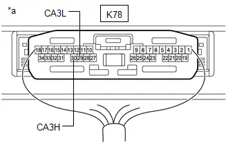
| NG |

| GO TO STEP 29 |
|

| 3. | CHECK FOR SHORT TO B IN CAN BUS LINE |
(a) Measure the resistance according to the value(s) in the table below.
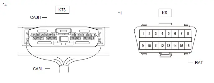
| *1 | DLC3 | - | - |
| *a | Component with harness connected (Central Gateway ECU (Network Gateway ECU)) | - | - |
Standard Resistance:
 Click Location & Routing(K78,K8) Click Connector(K78) Click Connector(K8)
 | Tester Connection | Condition | Specified Condition |
|---|---|---|
| K78-30 (CA3H) - K8-16 (BAT) | Cable disconnected from negative (-) auxiliary battery terminal | 6 kΩ or higher |
| K78-29 (CA3L) - K8-16 (BAT) |
| NG |

| GO TO STEP 17 |
|

| 4. | CHECK FOR SHORT TO GND IN CAN BUS LINE |
(a) Measure the resistance according to the value(s) in the table below.
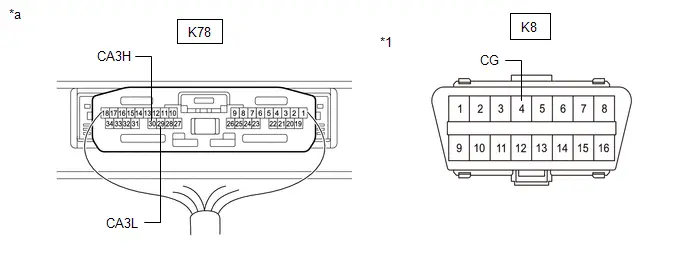
| *1 | DLC3 | - | - |
| *a | Component with harness connected (Central Gateway ECU (Network Gateway ECU)) | - | - |
Standard Resistance:
 Click Location & Routing(K78,K8) Click Connector(K78) Click Connector(K8)
 | Tester Connection | Condition | Specified Condition |
|---|---|---|
| K78-30 (CA3H) - K8-4 (CG) | Cable disconnected from negative (-) auxiliary battery terminal | 200 Ω or higher |
| K78-29 (CA3L) - K8-4 (CG) |
| OK |

| REPLACE CENTRAL GATEWAY ECU (NETWORK GATEWAY ECU) |
|

| 5. | CHECK FOR SHORT TO GND IN CAN BUS LINE (NO. 10 GLOBAL CAN JUNCTION CONNECTOR - CENTRAL GATEWAY ECU (NETWORK GATEWAY ECU)) |
(a) Disconnect the K110 No. 10 global CAN junction connector.
(b) Measure the resistance according to the value(s) in the table below.
Standard Resistance:
 Click Location & Routing(K110,K8) Click Connector(K110) Click Connector(K8)
 | Tester Connection | Condition | Specified Condition |
|---|---|---|
| K110-4 (CANH) - K8-4 (CG) | Cable disconnected from negative (-) auxiliary battery terminal | 200 Ω or higher |
| K110-15 (CANL) - K8-4 (CG) |
| NG |

| GO TO STEP 12 |
|

| 6. | CHECK FOR SHORT TO GND IN CAN BUS LINE (NO. 10 GLOBAL CAN JUNCTION CONNECTOR - COMBINATION METER ASSEMBLY) |
(a) Measure the resistance according to the value(s) in the table below.
Standard Resistance:
 Click Location & Routing(K110,K8) Click Connector(K110) Click Connector(K8)
 | Tester Connection | Condition | Specified Condition |
|---|---|---|
| K110-3 (CANH) - K8-4 (CG) | Cable disconnected from negative (-) auxiliary battery terminal | 200 Ω or higher |
| K110-14 (CANL) - K8-4 (CG) |
| NG |

| GO TO STEP 13 |
|

| 7. | CHECK FOR SHORT TO GND IN CAN BUS LINE (NO. 10 GLOBAL CAN JUNCTION CONNECTOR - RADIO AND DISPLAY RECEIVER ASSEMBLY) |
(a) Measure the resistance according to the value(s) in the table below.
Standard Resistance:
 Click Location & Routing(K110,K8) Click Connector(K110) Click Connector(K8)
 | Tester Connection | Condition | Specified Condition |
|---|---|---|
| K110-1 (CANH) - K8-4 (CG) | Cable disconnected from negative (-) auxiliary battery terminal | 200 Ω or higher |
| K110-12 (CANL) - K8-4 (CG) |
| NG |

| GO TO STEP 14 |
|

| 8. | CHECK Toyota Prius Vehicle TYPE |
(a) Check vehicle type.
| Result | Proceed to |
|---|---|
| w/ Telematics Transceiver | A |
| w/o Telematics Transceiver | B |
| B |

| GO TO STEP 10 |
|

| 9. | CHECK FOR SHORT TO GND IN CAN BUS LINE (NO. 10 GLOBAL CAN JUNCTION CONNECTOR - DCM (TELEMATICS TRANSCEIVER)) |
(a) Measure the resistance according to the value(s) in the table below.
Standard Resistance:
 Click Location & Routing(K110,K8) Click Connector(K110) Click Connector(K8)
 | Tester Connection | Condition | Specified Condition |
|---|---|---|
| K110-2 (CANH) - K8-4 (CG) | Cable disconnected from negative (-) auxiliary battery terminal | 200 Ω or higher |
| K110-13 (CANL) - K8-4 (CG) |
| NG |

| GO TO STEP 15 |
|

| 10. | CHECK Toyota Prius Vehicle TYPE |
(a) Check vehicle type.
| Result | Proceed to |
|---|---|
| w/ Digital Inner Mirror System | A |
| w/o Digital Inner Mirror System | B |
| B |

| REPLACE NO. 10 GLOBAL CAN JUNCTION CONNECTOR |
|

| 11. | CHECK FOR SHORT TO GND IN CAN BUS LINE (NO. 10 GLOBAL CAN JUNCTION CONNECTOR - INNER REAR VIEW MIRROR ASSEMBLY) |
(a) Measure the resistance according to the value(s) in the table below.
Standard Resistance:
 Click Location & Routing(K110,K8) Click Connector(K110) Click Connector(K8)
 | Tester Connection | Condition | Specified Condition |
|---|---|---|
| K110-6 (CANH) - K8-4 (CG) | Cable disconnected from negative (-) auxiliary battery terminal | 200 Ω or higher |
| K110-17 (CANL) - K8-4 (CG) |
| OK |

| REPLACE NO. 10 GLOBAL CAN JUNCTION CONNECTOR |
| NG |

| GO TO STEP 16 |
| 12. | CHECK FOR SHORT TO GND IN CAN BUS LINE (NO. 10 GLOBAL CAN JUNCTION CONNECTOR - CENTRAL GATEWAY ECU (NETWORK GATEWAY ECU)) |
(a) Disconnect the K78 central gateway ECU (network gateway ECU) connector.
(b) Measure the resistance according to the value(s) in the table below.
Standard Resistance:
 Click Location & Routing(K110,K8) Click Connector(K110) Click Connector(K8)
 | Tester Connection | Condition | Specified Condition |
|---|---|---|
| K110-4 (CANH) - K8-4 (CG) | Cable disconnected from negative (-) auxiliary battery terminal | 200 Ω or higher |
| K110-15 (CANL) - K8-4 (CG) |
| OK |

| REPLACE CENTRAL GATEWAY ECU (NETWORK GATEWAY ECU) |
| NG |

| REPAIR OR REPLACE CAN MAIN BUS LINE OR CONNECTOR (NO. 10 GLOBAL CAN JUNCTION CONNECTOR - CENTRAL GATEWAY ECU (NETWORK GATEWAY ECU)) |
| 13. | CHECK FOR SHORT TO GND IN CAN BUS LINE (NO. 10 GLOBAL CAN JUNCTION CONNECTOR - COMBINATION METER ASSEMBLY) |
(a) Disconnect the K19 combination meter assembly connector.
(b) Measure the resistance according to the value(s) in the table below.
Standard Resistance:
 Click Location & Routing(K110,K8) Click Connector(K110) Click Connector(K8)
 | Tester Connection | Condition | Specified Condition |
|---|---|---|
| K110-3 (CANH) - K8-4 (CG) | Cable disconnected from negative (-) auxiliary battery terminal | 200 Ω or higher |
| K110-14 (CANL) - K8-4 (CG) |
| OK |

| REPLACE COMBINATION METER ASSEMBLY |
| NG |

| REPAIR OR REPLACE CAN MAIN BUS LINE OR CONNECTOR (NO. 10 GLOBAL CAN JUNCTION CONNECTOR - COMBINATION METER ASSEMBLY) |
| 14. | CHECK FOR SHORT TO GND IN CAN BUS LINE (NO. 10 GLOBAL CAN JUNCTION CONNECTOR - RADIO AND DISPLAY RECEIVER ASSEMBLY) |
(a) Disconnect the K81 radio and display receiver assembly connector.
(b) Measure the resistance according to the value(s) in the table below.
Standard Resistance:
 Click Location & Routing(K110,K8) Click Connector(K110) Click Connector(K8)
 | Tester Connection | Condition | Specified Condition |
|---|---|---|
| K110-1 (CANH) - K8-4 (CG) | Cable disconnected from negative (-) auxiliary battery terminal | 200 Ω or higher |
| K110-12 (CANL) - K8-4 (CG) |
| OK |

| REPLACE RADIO AND DISPLAY RECEIVER ASSEMBLY |
| NG |

| REPAIR OR REPLACE CAN BRANCH LINE OR CONNECTOR (NO. 10 GLOBAL CAN JUNCTION CONNECTOR - RADIO AND DISPLAY RECEIVER ASSEMBLY) |
| 15. | CHECK FOR SHORT TO GND IN CAN BUS LINE (NO. 10 GLOBAL CAN JUNCTION CONNECTOR - DCM (TELEMATICS TRANSCEIVER)) |
(a) Disconnect the K9 DCM (telematics transceiver) connector.
(b) Measure the resistance according to the value(s) in the table below.
Standard Resistance:
 Click Location & Routing(K110,K8) Click Connector(K110) Click Connector(K8)
 | Tester Connection | Condition | Specified Condition |
|---|---|---|
| K110-2 (CANH) - K8-4 (CG) | Cable disconnected from negative (-) auxiliary battery terminal | 200 Ω or higher |
| K110-13 (CANL) - K8-4 (CG) |
| OK |

| REPLACE DCM (TELEMATICS TRANSCEIVER) |
| NG |

| REPAIR OR REPLACE CAN BRANCH LINE OR CONNECTOR (NO. 10 GLOBAL CAN JUNCTION CONNECTOR - DCM (TELEMATICS TRANSCEIVER)) |
| 16. | CHECK FOR SHORT TO GND IN CAN BUS LINE (NO. 10 GLOBAL CAN JUNCTION CONNECTOR - INNER REAR VIEW MIRROR ASSEMBLY) |
(a) Disconnect the U12 inner rear view mirror assembly connector.
(b) Measure the resistance according to the value(s) in the table below.
Standard Resistance:
 Click Location & Routing(K110,K8) Click Connector(K110) Click Connector(K8)
 | Tester Connection | Condition | Specified Condition |
|---|---|---|
| K110-6 (CANH) - K8-4 (CG) | Cable disconnected from negative (-) auxiliary battery terminal | 200 Ω or higher |
| K110-17 (CANL) - K8-4 (CG) |
| OK |

| REPLACE INNER REAR VIEW MIRROR ASSEMBLY |
| NG |

| REPAIR OR REPLACE CAN BRANCH LINE OR CONNECTOR (NO. 10 GLOBAL CAN JUNCTION CONNECTOR - INNER REAR VIEW MIRROR ASSEMBLY) |
| 17. | CHECK FOR SHORT TO B IN CAN BUS LINE (NO. 10 GLOBAL CAN JUNCTION CONNECTOR - CENTRAL GATEWAY ECU (NETWORK GATEWAY ECU)) |
(a) Disconnect the K110 No. 10 global CAN junction connector.
(b) Measure the resistance according to the value(s) in the table below.
Standard Resistance:
 Click Location & Routing(K110,K8) Click Connector(K110) Click Connector(K8)
 | Tester Connection | Condition | Specified Condition |
|---|---|---|
| K110-4 (CANH) - K8-16 (BAT) | Cable disconnected from negative (-) auxiliary battery terminal | 6 kΩ or higher |
| K110-15 (CANL) - K8-16 (BAT) |
| NG |

| GO TO STEP 24 |
|

| 18. | CHECK FOR SHORT TO B IN CAN BUS LINE (NO. 10 GLOBAL CAN JUNCTION CONNECTOR - COMBINATION METER ASSEMBLY) |
(a) Measure the resistance according to the value(s) in the table below.
Standard Resistance:
 Click Location & Routing(K110,K8) Click Connector(K110) Click Connector(K8)
 | Tester Connection | Condition | Specified Condition |
|---|---|---|
| K110-3 (CANH) - K8-16 (BAT) | Cable disconnected from negative (-) auxiliary battery terminal | 6 kΩ or higher |
| K110-14 (CANL) - K8-16 (BAT) |
| NG |

| GO TO STEP 25 |
|

| 19. | CHECK FOR SHORT TO B IN CAN BUS LINE (NO. 10 GLOBAL CAN JUNCTION CONNECTOR - RADIO AND DISPLAY RECEIVER ASSEMBLY) |
(a) Measure the resistance according to the value(s) in the table below.
Standard Resistance:
 Click Location & Routing(K110,K8) Click Connector(K110) Click Connector(K8)
 | Tester Connection | Condition | Specified Condition |
|---|---|---|
| K110-1 (CANH) - K8-16 (BAT) | Cable disconnected from negative (-) auxiliary battery terminal | 6 kΩ or higher |
| K110-12 (CANL) - K8-16 (BAT) |
| NG |

| GO TO STEP 26 |
|

| 20. | CHECK Toyota Prius Vehicle TYPE |
(a) Check vehicle type.
| Result | Proceed to |
|---|---|
| w/ Telematics Transceiver | A |
| w/o Telematics Transceiver | B |
| B |

| GO TO STEP 22 |
|

| 21. | CHECK FOR SHORT TO B IN CAN BUS LINE (NO. 10 GLOBAL CAN JUNCTION CONNECTOR - DCM (TELEMATICS TRANSCEIVER)) |
(a) Measure the resistance according to the value(s) in the table below.
Standard Resistance:
 Click Location & Routing(K110,K8) Click Connector(K110) Click Connector(K8)
 | Tester Connection | Condition | Specified Condition |
|---|---|---|
| K110-2 (CANH) - K8-16 (BAT) | Cable disconnected from negative (-) auxiliary battery terminal | 6 kΩ or higher |
| K110-13 (CANL) - K8-16 (BAT) |
| NG |

| GO TO STEP 27 |
|

| 22. | CHECK Toyota Prius Vehicle TYPE |
(a) Check vehicle type.
| Result | Proceed to |
|---|---|
| w/ Digital Inner Mirror System | A |
| w/o Digital Inner Mirror System | B |
| B |

| REPLACE NO. 10 GLOBAL CAN JUNCTION CONNECTOR |
|

| 23. | CHECK FOR SHORT TO B IN CAN BUS LINE (NO. 10 GLOBAL CAN JUNCTION CONNECTOR - INNER REAR VIEW MIRROR ASSEMBLY) |
(a) Measure the resistance according to the value(s) in the table below.
Standard Resistance:
 Click Location & Routing(K110,K8) Click Connector(K110) Click Connector(K8)
 | Tester Connection | Condition | Specified Condition |
|---|---|---|
| K110-6 (CANH) - K8-16 (BAT) | Cable disconnected from negative (-) auxiliary battery terminal | 6 kΩ or higher |
| K110-17 (CANL) - K8-16 (BAT) |
| OK |

| REPLACE NO. 10 GLOBAL CAN JUNCTION CONNECTOR |
| NG |

| GO TO STEP 28 |
| 24. | CHECK FOR SHORT TO B IN CAN BUS LINE (NO. 10 GLOBAL CAN JUNCTION CONNECTOR - CENTRAL GATEWAY ECU (NETWORK GATEWAY ECU)) |
(a) Disconnect the K78 central gateway ECU (network gateway ECU) connector.
(b) Measure the resistance according to the value(s) in the table below.
Standard Resistance:
 Click Location & Routing(K110,K8) Click Connector(K110) Click Connector(K8)
 | Tester Connection | Condition | Specified Condition |
|---|---|---|
| K110-4 (CANH) - K8-16 (BAT) | Cable disconnected from negative (-) auxiliary battery terminal | 6 kΩ or higher |
| K110-15 (CANL) - K8-16 (BAT) |
| OK |

| REPLACE CENTRAL GATEWAY ECU (NETWORK GATEWAY ECU) |
| NG |

| REPAIR OR REPLACE CAN MAIN BUS LINE OR CONNECTOR (NO. 10 GLOBAL CAN JUNCTION CONNECTOR - CENTRAL GATEWAY ECU (NETWORK GATEWAY ECU)) |
| 25. | CHECK FOR SHORT TO B IN CAN BUS LINE (NO. 10 GLOBAL CAN JUNCTION CONNECTOR - COMBINATION METER ASSEMBLY) |
(a) Disconnect the K19 combination meter assembly connector.
(b) Measure the resistance according to the value(s) in the table below.
Standard Resistance:
 Click Location & Routing(K110,K8) Click Connector(K110) Click Connector(K8)
 | Tester Connection | Condition | Specified Condition |
|---|---|---|
| K110-3 (CANH) - K8-16 (BAT) | Cable disconnected from negative (-) auxiliary battery terminal | 6 kΩ or higher |
| K110-14 (CANL) - K8-16 (BAT) |
| OK |

| REPLACE COMBINATION METER ASSEMBLY |
| NG |

| REPAIR OR REPLACE CAN MAIN BUS LINE OR CONNECTOR (NO. 10 GLOBAL CAN JUNCTION CONNECTOR - COMBINATION METER ASSEMBLY) |
| 26. | CHECK FOR SHORT TO B IN CAN BUS LINE (NO. 10 GLOBAL CAN JUNCTION CONNECTOR - RADIO AND DISPLAY RECEIVER ASSEMBLY) |
(a) Disconnect the K81 radio and display receiver assembly connector.
(b) Measure the resistance according to the value(s) in the table below.
Standard Resistance:
 Click Location & Routing(K110,K8) Click Connector(K110) Click Connector(K8)
 | Tester Connection | Condition | Specified Condition |
|---|---|---|
| K110-1 (CANH) - K8-16 (BAT) | Cable disconnected from negative (-) auxiliary battery terminal | 6 kΩ or higher |
| K110-12 (CANL) - K8-6 (BAT) |
| OK |

| REPLACE RADIO AND DISPLAY RECEIVER ASSEMBLY |
| NG |

| REPAIR OR REPLACE CAN BRANCH LINE OR CONNECTOR (NO. 10 GLOBAL CAN JUNCTION CONNECTOR - RADIO AND DISPLAY RECEIVER ASSEMBLY) |
| 27. | CHECK FOR SHORT TO B IN CAN BUS LINE (NO. 10 GLOBAL CAN JUNCTION CONNECTOR - DCM (TELEMATICS TRANSCEIVER)) |
(a) Disconnect the K9 DCM (telematics transceiver) connector.
(b) Measure the resistance according to the value(s) in the table below.
Standard Resistance:
 Click Location & Routing(K110,K8) Click Connector(K110) Click Connector(K8)
 | Tester Connection | Condition | Specified Condition |
|---|---|---|
| K110-2 (CANH) - K8-16 (BAT) | Cable disconnected from negative (-) auxiliary battery terminal | 6 kΩ or higher |
| K110-13 (CANL) - K8-16 (BAT) |
| OK |

| REPLACE DCM (TELEMATICS TRANSCEIVER) |
| NG |

| REPAIR OR REPLACE CAN BRANCH LINE OR CONNECTOR (NO. 10 GLOBAL CAN JUNCTION CONNECTOR - DCM (TELEMATICS TRANSCEIVER)) |
| 28. | CHECK FOR SHORT TO B IN CAN BUS LINE (NO. 10 GLOBAL CAN JUNCTION CONNECTOR - INNER REAR VIEW MIRROR ASSEMBLY) |
(a) Disconnect the U12 inner rear view mirror assembly connector.
(b) Measure the resistance according to the value(s) in the table below.
Standard Resistance:
 Click Location & Routing(K110,K8) Click Connector(K110) Click Connector(K8)
 | Tester Connection | Condition | Specified Condition |
|---|---|---|
| K110-6 (CANH) - K8-16 (BAT) | Cable disconnected from negative (-) auxiliary battery terminal | 6 kΩ or higher |
| K110-17 (CANL) - K8-16 (BAT) |
| OK |

| REPLACE INNER REAR VIEW MIRROR ASSEMBLY |
| NG |

| REPAIR OR REPLACE CAN BRANCH LINE OR CONNECTOR (NO. 10 GLOBAL CAN JUNCTION CONNECTOR - INNER REAR VIEW MIRROR ASSEMBLY) |
| 29. | CHECK FOR SHORT IN CAN BUS LINES (NO. 10 GLOBAL CAN JUNCTION CONNECTOR - CENTRAL GATEWAY ECU (NETWORK GATEWAY ECU)) |
(a) Disconnect the K110 No. 10 global CAN junction connector.
(b) Measure the resistance according to the value(s) in the table below.
Standard Resistance:
 Click Location & Routing(K110) Click Connector(K110)
 | Tester Connection | Condition | Specified Condition |
|---|---|---|
| K110-4 (CANH) - K110-15 (CANL) | Cable disconnected from negative (-) auxiliary battery terminal | 108 to 132 Ω |
| NG |

| GO TO STEP 36 |
|

| 30. | CHECK FOR SHORT IN CAN BUS LINES (NO. 10 GLOBAL CAN JUNCTION CONNECTOR - COMBINATION METER ASSEMBLY) |
(a) Measure the resistance according to the value(s) in the table below.
Standard Resistance:
 Click Location & Routing(K110) Click Connector(K110)
 | Tester Connection | Condition | Specified Condition |
|---|---|---|
| K110-3 (CANH) - K110-14 (CANL) | Cable disconnected from negative (-) auxiliary battery terminal | 108 to 132 Ω |
| NG |

| GO TO STEP 37 |
|

| 31. | CHECK FOR SHORT IN CAN BUS LINES (NO. 10 GLOBAL CAN JUNCTION CONNECTOR - RADIO AND DISPLAY RECEIVER ASSEMBLY) |
(a) Measure the resistance according to the value(s) in the table below.
Standard Resistance:
 Click Location & Routing(K110) Click Connector(K110)
 | Tester Connection | Condition | Specified Condition |
|---|---|---|
| K110-1 (CANH) - K110-12 (CANL) | Cable disconnected from negative (-) auxiliary battery terminal | 200 Ω or higher |
| NG |

| GO TO STEP 38 |
|

| 32. | CHECK Toyota Prius Vehicle TYPE |
(a) Check vehicle type.
| Result | Proceed to |
|---|---|
| w/ Telematics Transceiver | A |
| w/o Telematics Transceiver | B |
| B |

| GO TO STEP 34 |
|

| 33. | CHECK FOR SHORT IN CAN BUS LINES (NO. 10 GLOBAL CAN JUNCTION CONNECTOR - DCM (TELEMATICS TRANSCEIVER)) |
(a) Measure the resistance according to the value(s) in the table below.
Standard Resistance:
 Click Location & Routing(K110) Click Connector(K110)
 | Tester Connection | Condition | Specified Condition |
|---|---|---|
| K110-2 (CANH) - K110-13 (CANL) | Cable disconnected from negative (-) auxiliary battery terminal | 200 Ω or higher |
| NG |

| GO TO STEP 39 |
|

| 34. | CHECK Toyota Prius Vehicle TYPE |
(a) Check vehicle type.
| Result | Proceed to |
|---|---|
| w/ Digital Inner Mirror System | A |
| w/o Digital Inner Mirror System | B |
| B |

| REPLACE NO. 10 GLOBAL CAN JUNCTION CONNECTOR |
|

| 35. | CHECK FOR SHORT IN CAN BUS LINES (NO. 10 GLOBAL CAN JUNCTION CONNECTOR - INNER REAR VIEW MIRROR ASSEMBLY) |
(a) Measure the resistance according to the value(s) in the table below.
Standard Resistance:
 Click Location & Routing(K110) Click Connector(K110)
 | Tester Connection | Condition | Specified Condition |
|---|---|---|
| K110-6 (CANH) - K110-17 (CANL) | Cable disconnected from negative (-) auxiliary battery terminal | 200 Ω or higher |
| OK |

| REPLACE NO. 10 GLOBAL CAN JUNCTION CONNECTOR |
| NG |

| GO TO STEP 40 |
| 36. | CHECK FOR SHORT IN CAN BUS LINES (NO. 10 GLOBAL CAN JUNCTION CONNECTOR - CENTRAL GATEWAY ECU (NETWORK GATEWAY ECU)) |
(a) Disconnect the K78 central gateway ECU (network gateway ECU) connector.
(b) Measure the resistance according to the value(s) in the table below.
Standard Resistance:
 Click Location & Routing(K110) Click Connector(K110)
 | Tester Connection | Condition | Specified Condition |
|---|---|---|
| K110-4 (CANH) - K110-15 (CANL) | Cable disconnected from negative (-) auxiliary battery terminal | 1 MΩ or higher |
| OK |

| REPLACE CENTRAL GATEWAY ECU (NETWORK GATEWAY ECU) |
| NG |

| REPAIR OR REPLACE CAN MAIN BUS LINES OR CONNECTOR (NO. 10 GLOBAL CAN JUNCTION CONNECTOR - CENTRAL GATEWAY ECU (NETWORK GATEWAY ECU)) |
| 37. | CHECK FOR SHORT IN CAN BUS LINES (NO. 10 GLOBAL CAN JUNCTION CONNECTOR - COMBINATION METER ASSEMBLY) |
(a) Disconnect the K19 combination meter assembly connector.
(b) Measure the resistance according to the value(s) in the table below.
Standard Resistance:
 Click Location & Routing(K110) Click Connector(K110)
 | Tester Connection | Condition | Specified Condition |
|---|---|---|
| K110-3 (CANH) - K110-14 (CANL) | Cable disconnected from negative (-) auxiliary battery terminal | 1 MΩ or higher |
| OK |

| REPLACE COMBINATION METER ASSEMBLY |
| NG |

| REPAIR OR REPLACE CAN MAIN BUS LINES OR CONNECTOR (NO. 10 GLOBAL CAN JUNCTION CONNECTOR - COMBINATION METER ASSEMBLY) |
| 38. | CHECK FOR SHORT IN CAN BUS LINES (NO. 10 GLOBAL CAN JUNCTION CONNECTOR - RADIO AND DISPLAY RECEIVER ASSEMBLY) |
(a) Disconnect the K81 radio and display receiver assembly connector.
(b) Measure the resistance according to the value(s) in the table below.
Standard Resistance:
 Click Location & Routing(K110) Click Connector(K110)
 | Tester Connection | Condition | Specified Condition |
|---|---|---|
| K110-1 (CANH) - K110-12 (CANL) | Cable disconnected from negative (-) auxiliary battery terminal | 1 MΩ or higher |
| OK |

| REPLACE RADIO AND DISPLAY RECEIVER ASSEMBLY |
| NG |

| REPAIR OR REPLACE CAN BRANCH LINES OR CONNECTOR (NO. 10 GLOBAL CAN JUNCTION CONNECTOR - RADIO AND DISPLAY RECEIVER ASSEMBLY) |
| 39. | CHECK FOR SHORT IN CAN BUS LINES (NO. 10 GLOBAL CAN JUNCTION CONNECTOR - DCM (TELEMATICS TRANSCEIVER)) |
(a) Disconnect the K9 DCM (telematics transceiver) connector.
(b) Measure the resistance according to the value(s) in the table below.
Standard Resistance:
 Click Location & Routing(K110) Click Connector(K110)
 | Tester Connection | Condition | Specified Condition |
|---|---|---|
| K110-2 (CANH) - K110-13 (CANL) | Cable disconnected from negative (-) auxiliary battery terminal | 1 MΩ or higher |
| OK |

| REPLACE DCM (TELEMATICS TRANSCEIVER) |
| NG |

| REPAIR OR REPLACE CAN BRANCH LINES OR CONNECTOR (NO. 10 GLOBAL CAN JUNCTION CONNECTOR - DCM (TELEMATICS TRANSCEIVER)) |
| 40. | CHECK FOR SHORT IN CAN BUS LINES (NO. 10 GLOBAL CAN JUNCTION CONNECTOR - INNER REAR VIEW MIRROR ASSEMBLY) |
(a) Disconnect the U12 inner rear view mirror assembly connector.
(b) Measure the resistance according to the value(s) in the table below.
Standard Resistance:
 Click Location & Routing(K110) Click Connector(K110)
 | Tester Connection | Condition | Specified Condition |
|---|---|---|
| K110-6 (CANH) - K110-17 (CANL) | Cable disconnected from negative (-) auxiliary battery terminal | 1 MΩ or higher |
| OK |

| REPLACE INNER REAR VIEW MIRROR ASSEMBLY |
| NG |

| REPAIR OR REPLACE CAN BRANCH LINES OR CONNECTOR (NO. 10 GLOBAL CAN JUNCTION CONNECTOR - INNER REAR VIEW MIRROR ASSEMBLY) |
| 41. | CHECK FOR OPEN IN CAN MAIN BUS LINES (CENTRAL GATEWAY ECU (NETWORK GATEWAY ECU)) |
(a) Disconnect the K78 central gateway ECU (network gateway ECU) connector.
(b) Measure the resistance according to the value(s) in the table below.
Standard Resistance:
 Click Location & Routing(K78) Click Connector(K78)
 | Tester Connection | Condition | Specified Condition |
|---|---|---|
| K78-30 (CA3H) - K78-29 (CA3L) | Cable disconnected from negative (-) auxiliary battery terminal | 108 to 132 Ω |
| OK |

| REPLACE CENTRAL GATEWAY ECU (NETWORK GATEWAY ECU) |
|

| 42. | CHECK FOR OPEN IN CAN MAIN BUS LINES (NO. 10 GLOBAL CAN JUNCTION CONNECTOR - CENTRAL GATEWAY ECU (NETWORK GATEWAY ECU)) |
(a) Reconnect the K78 central gateway ECU (network gateway ECU) connector.
(b) Disconnect the K110 No. 10 global CAN junction connector.
(c) Measure the resistance according to the value(s) in the table below.
Standard Resistance:
 Click Location & Routing(K110) Click Connector(K110)
 | Tester Connection | Condition | Specified Condition |
|---|---|---|
| K110-4 (CANH) - K110-15 (CANL) | Cable disconnected from negative (-) auxiliary battery terminal | 108 to 132 Ω |
| NG |

| REPAIR OR REPLACE CAN MAIN BUS LINES OR CONNECTOR (NO. 10 GLOBAL CAN JUNCTION CONNECTOR - CENTRAL GATEWAY ECU (NETWORK GATEWAY ECU)) |
|

| 43. | CHECK FOR OPEN IN CAN MAIN BUS LINES (NO. 10 GLOBAL CAN JUNCTION CONNECTOR - COMBINATION METER ASSEMBLY) |
(a) Measure the resistance according to the value(s) in the table below.
Standard Resistance:
 Click Location & Routing(K110) Click Connector(K110)
 | Tester Connection | Condition | Specified Condition |
|---|---|---|
| K110-3 (CANH) - K110-14 (CANL) | Cable disconnected from negative (-) auxiliary battery terminal | 108 to 132 Ω |
| OK |

| REPLACE NO. 10 GLOBAL CAN JUNCTION CONNECTOR |
|

| 44. | CHECK FOR OPEN IN CAN MAIN BUS LINES (COMBINATION METER ASSEMBLY) |
(a) Reconnect the K110 No. 10 global CAN junction connector.
(b) Disconnect the K19 combination meter assembly connector.
(c) Measure the resistance according to the value(s) in the table below.
Standard Resistance:
 Click Location & Routing(K19) Click Connector(K19)
 | Tester Connection | Condition | Specified Condition |
|---|---|---|
| K19-31 (CANH) - K19-14 (CANL) | Cable disconnected from negative (-) auxiliary battery terminal | 108 to 132 Ω |
| OK |

| REPLACE COMBINATION METER ASSEMBLY |
| NG |

| REPAIR OR REPLACE CAN MAIN BUS LINES OR CONNECTOR (COMBINATION METER ASSEMBLY - NO. 10 GLOBAL CAN JUNCTION CONNECTOR) |
Check Bus 4 Line
DESCRIPTION
| Symptom | Trouble Area |
|---|---|
| There are ECUs or sensors that display a communication stop on the bus diagnostic screen. Or, there are ECUs or sensors that display communication stop history on the "Detail" screen. |
|
WIRING DIAGRAM
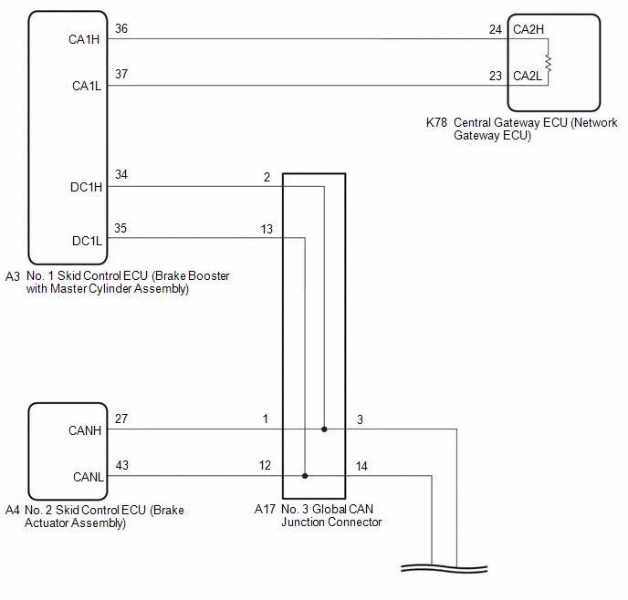
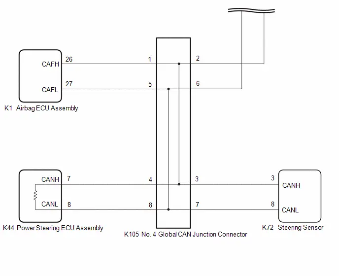
CAUTION / NOTICE / HINT
CAUTION:
When performing the confirmation driving pattern, obey all speed limits and traffic laws.
NOTICE:
-
Because the order of diagnosis is important to allow correct diagnosis, make sure to begin troubleshooting using How to Proceed with Troubleshooting when CAN communication system related DTCs are output.
Click here

- Before measuring the resistance of the CAN bus, turn the ignition switch off and leave the Toyota Prius vehicle for 1 minute or more without operating the key or any switches, or opening or closing the doors. After that, disconnect the cable from the negative (-) auxiliary battery terminal and leave the vehicle for 1 minute or more before measuring the resistance.
-
After the ignition switch is turned off, there may be a waiting time before disconnecting the negative (-) auxiliary battery terminal.
Click here

-
When disconnecting and reconnecting the auxiliary battery.
HINT:
When disconnecting and reconnecting the auxiliary battery, there is an automatic learning function that completes learning when the respective system is used.
Click here


-
Some parts must be initialized and set when replacing or removing and installing parts.
Click here


-
After performing repairs, perform the DTC check procedure and confirm that the DTCs are not output again.
DTC check procedure: Turn the ignition switch to ON and wait for 1 minute or more. Then operate the suspected malfunctioning system and drive the Toyota Prius vehicle at 60 km/h (37 mph) or more for 5 minutes or more.
-
After the repair, perform the CAN bus check and check that all the ECUs and sensors connected to the CAN communication system are displayed as normal.
Click here

- When disconnecting a wire harness of any component connected to the supply power of the integrated capacitor (integration control supply) or when removing the integrated capacitor (integration control supply), make sure to wait 5 minutes or more after turning the ignition switch off for self-diagnosis to complete and the voltage of the integrated capacitor (integration control supply) to discharge.
HINT:
- Before disconnecting related connectors for inspection, push in on each connector body to check that the connector is not loose or disconnected.
- When a connector is disconnected, check that the terminals and connector body are not cracked, deformed or corroded.
PROCEDURE
| 1. | CHECK FOR OPEN IN CAN MAIN BUS LINES |
(a) Disconnect the cable from the negative (-) auxiliary battery terminal.
| (b) Measure the resistance according to the value(s) in the table below. Standard Resistance:  Click Location & Routing(K78) Click Connector(K78) Click Location & Routing(K78) Click Connector(K78)
|
|
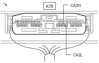
| NG |

| GO TO STEP 47 |
|

| 2. | CHECK FOR SHORT IN CAN BUS LINES |
| (a) Measure the resistance according to the value(s) in the table below. Standard Resistance:  Click Location & Routing(K78) Click Connector(K78) Click Location & Routing(K78) Click Connector(K78)
|
|

| NG |

| GO TO STEP 33 |
|

| 3. | CHECK FOR SHORT TO B IN CAN BUS LINE |
(a) Measure the resistance according to the value(s) in the table below.
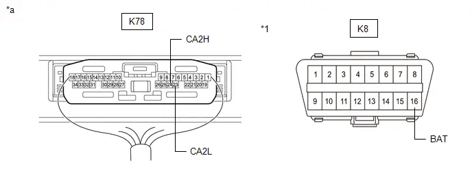
| *1 | DLC3 | - | - |
| *a | Component with harness connected (Central Gateway ECU (Network Gateway ECU)) | - | - |
Standard Resistance:
 Click Location & Routing(K78,K8) Click Connector(K78) Click Connector(K8)
 | Tester Connection | Condition | Specified Condition |
|---|---|---|
| K78-24 (CA2H) - K8-16 (BAT) | Cable disconnected from negative (-) auxiliary battery terminal | 6 kΩ or higher |
| K78-23 (CA2L) - K8-16 (BAT) |
| NG |

| GO TO STEP 19 |
|

| 4. | CHECK FOR SHORT TO GND IN CAN BUS LINE |
(a) Measure the resistance according to the value(s) in the table below.
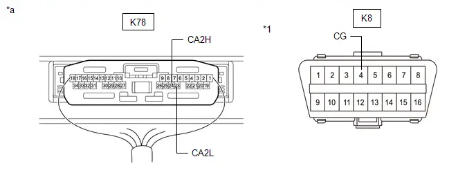
| *1 | DLC3 | - | - |
| *a | Component with harness connected (Central Gateway ECU (Network Gateway ECU)) | - | - |
Standard Resistance:
 Click Location & Routing(K78,K8) Click Connector(K78) Click Connector(K8)
 | Tester Connection | Condition | Specified Condition |
|---|---|---|
| K78-24 (CA2H) - K8-4 (CG) | Cable disconnected from negative (-) auxiliary battery terminal | 200 Ω or higher |
| K78-23 (CA2L) - K8-4 (CG) |
| OK |

| REPLACE CENTRAL GATEWAY ECU (NETWORK GATEWAY ECU) |
|

| 5. | CHECK FOR SHORT TO GND IN CAN BUS LINE (NO. 1 SKID CONTROL ECU (BRAKE BOOSTER WITH MASTER CYLINDER ASSEMBLY) - CENTRAL GATEWAY ECU (NETWORK GATEWAY ECU)) |
(a) Disconnect the A3 No. 1 skid control ECU (brake booster with master cylinder assembly) connector.
(b) Measure the resistance according to the value(s) in the table below.
Standard Resistance:
 Click Location & Routing(A3,K8) Click Connector(A3) Click Connector(K8)
 | Tester Connection | Condition | Specified Condition |
|---|---|---|
| A3-36 (CA1H) - K8-4 (CG) | Cable disconnected from negative (-) auxiliary battery terminal | 200 Ω or higher |
| A3-37 (CA1L) - K8-4 (CG) |
| NG |

| GO TO STEP 7 |
|

| 6. | CHECK FOR SHORT TO GND IN CAN BUS LINE (NO. 1 SKID CONTROL ECU (BRAKE BOOSTER WITH MASTER CYLINDER ASSEMBLY) - NO. 3 GLOBAL CAN JUNCTION CONNECTOR) |
(a) Measure the resistance according to the value(s) in the table below.
Standard Resistance:
 Click Location & Routing(A3,K8) Click Connector(A3) Click Connector(K8)
 | Tester Connection | Condition | Specified Condition |
|---|---|---|
| A3-34 (DC1H) - K8-4 (CG) | Cable disconnected from negative (-) auxiliary battery terminal | 200 Ω or higher |
| A3-35 (DC1L) - K8-4 (CG) |
| OK |

| REPLACE NO. 1 SKID CONTROL ECU (BRAKE BOOSTER WITH MASTER CYLINDER ASSEMBLY)
|


| NG |

| GO TO STEP 8 |
| 7. | CHECK FOR SHORT TO GND IN CAN BUS LINE (NO. 1 SKID CONTROL ECU (BRAKE BOOSTER WITH MASTER CYLINDER ASSEMBLY) - CENTRAL GATEWAY ECU (NETWORK GATEWAY ECU)) |
(a) Disconnect the K78 central gateway ECU (network gateway ECU) connector.
(b) Measure the resistance according to the value(s) in the table below.
Standard Resistance:
 Click Location & Routing(A3,K8) Click Connector(A3) Click Connector(K8)
 | Tester Connection | Condition | Specified Condition |
|---|---|---|
| A3-36 (CA1H) - K8-4 (CG) | Cable disconnected from negative (-) auxiliary battery terminal | 200 Ω or higher |
| A3-37 (CA1L) - K8-4 (CG) |
| OK |

| REPLACE CENTRAL GATEWAY ECU (NETWORK GATEWAY ECU) |
| NG |

| REPAIR OR REPLACE CAN MAIN BUS LINE OR CONNECTOR (NO. 1 SKID CONTROL ECU (BRAKE BOOSTER WITH MASTER CYLINDER ASSEMBLY) - CENTRAL GATEWAY ECU (NETWORK GATEWAY ECU)) |
| 8. | CHECK FOR SHORT TO GND IN CAN BUS LINE (NO. 3 GLOBAL CAN JUNCTION CONNECTOR - NO. 1 SKID CONTROL ECU (BRAKE BOOSTER WITH MASTER CYLINDER ASSEMBLY)) |
(a) Disconnect the A17 No. 3 global CAN junction connector.
(b) Measure the resistance according to the value(s) in the table below.
Standard Resistance:
 Click Location & Routing(A17,K8) Click Connector(A17) Click Connector(K8)
 | Tester Connection | Condition | Specified Condition |
|---|---|---|
| A17-2 (CANH) - K8-4 (CG) | Cable disconnected from negative (-) auxiliary battery terminal | 200 Ω or higher |
| A17-13 (CANL) - K8-4 (CG) |
| NG |

| REPAIR OR REPLACE CAN MAIN BUS LINE OR CONNECTOR (NO. 3 GLOBAL CAN JUNCTION CONNECTOR - NO. 1 SKID CONTROL ECU (BRAKE BOOSTER WITH MASTER CYLINDER ASSEMBLY)) |
|

| 9. | CHECK FOR SHORT TO GND IN CAN BUS LINE (NO. 3 GLOBAL CAN JUNCTION CONNECTOR - NO. 4 GLOBAL CAN JUNCTION CONNECTOR) |
(a) Measure the resistance according to the value(s) in the table below.
Standard Resistance:
 Click Location & Routing(A17,K8) Click Connector(A17) Click Connector(K8)
 | Tester Connection | Condition | Specified Condition |
|---|---|---|
| A17-3 (CANH) - K8-4 (CG) | Cable disconnected from negative (-) auxiliary battery terminal | 200 Ω or higher |
| A17-14 (CANL) - K8-4 (CG) |
| NG |

| GO TO STEP 12 |
|

| 10. | CHECK FOR SHORT TO GND IN CAN BUS LINE (NO. 3 GLOBAL CAN JUNCTION CONNECTOR - NO. 2 SKID CONTROL ECU (BRAKE ACTUATOR ASSEMBLY)) |
(a) Measure the resistance according to the value(s) in the table below.
Standard Resistance:
 Click Location & Routing(A17,K8) Click Connector(A17) Click Connector(K8)
 | Tester Connection | Condition | Specified Condition |
|---|---|---|
| A17-1 (CANH) - K8-4 (CG) | Cable disconnected from negative (-) auxiliary battery terminal | 200 Ω or higher |
| A17-12 (CANL) - K8-4 (CG) |
| OK |

| REPLACE NO. 3 GLOBAL CAN JUNCTION CONNECTOR |
|

| 11. | CHECK FOR SHORT TO GND IN CAN BUS LINE (NO. 3 GLOBAL CAN JUNCTION CONNECTOR - NO. 2 SKID CONTROL ECU (BRAKE ACTUATOR ASSEMBLY)) |
(a) Disconnect the A4 No. 2 skid control ECU (brake actuator assembly) connector.
(b) Measure the resistance according to the value(s) in the table below.
Standard Resistance:
 Click Location & Routing(A17,K8) Click Connector(A17) Click Connector(K8)
 | Tester Connection | Condition | Specified Condition |
|---|---|---|
| A17-1 (CANH) - K8-4 (CG) | Cable disconnected from negative (-) auxiliary battery terminal | 200 Ω or higher |
| A17-12 (CANL) - K8-4 (CG) |
| OK |

| REPLACE NO. 2 SKID CONTROL ECU (BRAKE ACTUATOR ASSEMBLY)
|


| NG |

| REPAIR OR REPLACE CAN BRANCH LINE OR CONNECTOR (NO. 3 GLOBAL CAN JUNCTION CONNECTOR - NO. 2 SKID CONTROL ECU (BRAKE ACTUATOR ASSEMBLY)) |
| 12. | CHECK FOR SHORT TO GND IN CAN BUS LINE (NO. 4 GLOBAL CAN JUNCTION CONNECTOR - NO. 3 GLOBAL CAN JUNCTION CONNECTOR) |
(a) Disconnect the K105 No. 4 global CAN junction connector.
(b) Measure the resistance according to the value(s) in the table below.
Standard Resistance:
 Click Location & Routing(K105,K8) Click Connector(K105) Click Connector(K8)
 | Tester Connection | Condition | Specified Condition |
|---|---|---|
| K105-2 (CANH) - K8-4 (CG) | Cable disconnected from negative (-) auxiliary battery terminal | 200 Ω or higher |
| K105-6 (CANL) - K8-4 (CG) |
| NG |

| REPAIR OR REPLACE CAN MAIN BUS LINE OR CONNECTOR (NO. 4 GLOBAL CAN JUNCTION CONNECTOR - NO. 3 GLOBAL CAN JUNCTION CONNECTOR) |
|

| 13. | CHECK FOR SHORT TO GND IN CAN BUS LINE (NO. 4 GLOBAL CAN JUNCTION CONNECTOR - POWER STEERING ECU ASSEMBLY) |
(a) Measure the resistance according to the value(s) in the table below.
Standard Resistance:
 Click Location & Routing(K105,K8) Click Connector(K105) Click Connector(K8)
 | Tester Connection | Condition | Specified Condition |
|---|---|---|
| K105-4 (CANH) - K8-4 (CG) | Cable disconnected from negative (-) auxiliary battery terminal | 200 Ω or higher |
| K105-8 (CANL) - K8-4 (CG) |
| NG |

| GO TO STEP 16 |
|

| 14. | CHECK FOR SHORT TO GND IN CAN BUS LINE (NO. 4 GLOBAL CAN JUNCTION CONNECTOR - AIRBAG ECU ASSEMBLY) |
(a) Measure the resistance according to the value(s) in the table below.
Standard Resistance:
 Click Location & Routing(K105,K8) Click Connector(K105) Click Connector(K8)
 | Tester Connection | Condition | Specified Condition |
|---|---|---|
| K105-1 (CANH) - K8-4 (CG) | Cable disconnected from negative (-) auxiliary battery terminal | 200 Ω or higher |
| K105-5 (CANL) - K8-4 (CG) |
| NG |

| GO TO STEP 17 |
|

| 15. | CHECK FOR SHORT TO GND IN CAN BUS LINE (NO. 4 GLOBAL CAN JUNCTION CONNECTOR - STEERING SENSOR) |
(a) Measure the resistance according to the value(s) in the table below.
Standard Resistance:
 Click Location & Routing(K105,K8) Click Connector(K105) Click Connector(K8)
 | Tester Connection | Condition | Specified Condition |
|---|---|---|
| K105-3 (CANH) - K8-4 (CG) | Cable disconnected from negative (-) auxiliary battery terminal | 200 Ω or higher |
| K105-7 (CANL) - K8-4 (CG) |
| OK |

| REPLACE NO. 4 GLOBAL CAN JUNCTION CONNECTOR |
| NG |

| GO TO STEP 18 |
| 16. | CHECK FOR SHORT TO GND IN CAN BUS LINE (NO. 4 GLOBAL CAN JUNCTION CONNECTOR - POWER STEERING ECU ASSEMBLY) |
(a) Disconnect the K44 power steering ECU assembly connector.
(b) Measure the resistance according to the value(s) in the table below.
Standard Resistance:
 Click Location & Routing(K105,K8) Click Connector(K105) Click Connector(K8)
 | Tester Connection | Condition | Specified Condition |
|---|---|---|
| K105-4 (CANH) - K8-4 (CG) | Cable disconnected from negative (-) auxiliary battery terminal | 200 Ω or higher |
| K105-8 (CANL) - K8-4 (CG) |
| OK |

| REPLACE POWER STEERING ECU ASSEMBLY
|


| NG |

| REPAIR OR REPLACE CAN MAIN BUS LINE OR CONNECTOR (NO. 4 GLOBAL CAN JUNCTION CONNECTOR - POWER STEERING ECU ASSEMBLY) |
| 17. | CHECK FOR SHORT TO GND IN CAN BUS LINE (NO. 4 GLOBAL CAN JUNCTION CONNECTOR - AIRBAG ECU ASSEMBLY) |
(a) Disconnect the K1 airbag ECU assembly connector.
(b) Measure the resistance according to the value(s) in the table below.
Standard Resistance:
 Click Location & Routing(K105,K8) Click Connector(K105) Click Connector(K8)
 | Tester Connection | Condition | Specified Condition |
|---|---|---|
| K105-1 (CANH) - K8-4 (CG) | Cable disconnected from negative (-) auxiliary battery terminal | 200 Ω or higher |
| K105-5 (CANL) - K8-4 (CG) |
| OK |

| REPLACE AIRBAG ECU ASSEMBLY
|


| NG |

| REPAIR OR REPLACE CAN BRANCH LINE OR CONNECTOR (NO. 4 GLOBAL CAN JUNCTION CONNECTOR - AIRBAG ECU ASSEMBLY) |
| 18. | CHECK FOR SHORT TO GND IN CAN BUS LINE (NO. 4 GLOBAL CAN JUNCTION CONNECTOR - STEERING SENSOR) |
(a) Disconnect the K72 steering sensor connector.
(b) Measure the resistance according to the value(s) in the table below.
Standard Resistance:
 Click Location & Routing(K105,K8) Click Connector(K105) Click Connector(K8)
 | Tester Connection | Condition | Specified Condition |
|---|---|---|
| K105-3 (CANH) - K8-4 (CG) | Cable disconnected from negative (-) auxiliary battery terminal | 200 Ω or higher |
| K105-7 (CANL) - K8-4 (CG) |
| OK |

| REPLACE STEERING SENSOR
|


| NG |

| REPAIR OR REPLACE CAN BRANCH LINE OR CONNECTOR (NO. 4 GLOBAL CAN JUNCTION CONNECTOR - STEERING SENSOR) |
| 19. | CHECK FOR SHORT TO B IN CAN BUS LINE (NO. 1 SKID CONTROL ECU (BRAKE BOOSTER WITH MASTER CYLINDER ASSEMBLY) - CENTRAL GATEWAY ECU (NETWORK GATEWAY ECU)) |
(a) Disconnect the A3 No. 1 skid control ECU (brake booster with master cylinder assembly) connector.
(b) Measure the resistance according to the value(s) in the table below.
Standard Resistance:
 Click Location & Routing(A3,K8) Click Connector(A3) Click Connector(K8)
 | Tester Connection | Condition | Specified Condition |
|---|---|---|
| A3-36 (CA1H) - K8-16 (BAT) | Cable disconnected from negative (-) auxiliary battery terminal | 6 kΩ or higher |
| A3-37 (CA1L) - K8-16 (BAT) |
| NG |

| GO TO STEP 21 |
|

| 20. | CHECK FOR SHORT TO B IN CAN BUS LINE (NO. 1 SKID CONTROL ECU (BRAKE BOOSTER WITH MASTER CYLINDER ASSEMBLY) - NO. 3 GLOBAL CAN JUNCTION CONNECTOR) |
(a) Measure the resistance according to the value(s) in the table below.
Standard Resistance:
 Click Location & Routing(A3,K8) Click Connector(A3) Click Connector(K8)
 | Tester Connection | Condition | Specified Condition |
|---|---|---|
| A3-34 (DC1H) - K8-16 (BAT) | Cable disconnected from negative (-) auxiliary battery terminal | 6 kΩ or higher |
| A3-35 (DC1L) - K8-16 (BAT) |
| OK |

| REPLACE NO. 1 SKID CONTROL ECU (BRAKE BOOSTER WITH MASTER CYLINDER ASSEMBLY)
|


| NG |

| GO TO STEP 22 |
| 21. | CHECK FOR SHORT TO B IN CAN BUS LINE (NO. 1 SKID CONTROL ECU (BRAKE BOOSTER WITH MASTER CYLINDER ASSEMBLY) - CENTRAL GATEWAY ECU (NETWORK GATEWAY ECU)) |
(a) Disconnect the K78 central gateway ECU (network gateway ECU) connector.
(b) Measure the resistance according to the value(s) in the table below.
Standard Resistance:
 Click Location & Routing(A3,K8) Click Connector(A3) Click Connector(K8)
 | Tester Connection | Condition | Specified Condition |
|---|---|---|
| A3-36 (CA1H) - K8-16 (BAT) | Cable disconnected from negative (-) auxiliary battery terminal | 6 kΩ or higher |
| A3-37 (CA1L) - K8-16 (BAT) |
| OK |

| REPLACE CENTRAL GATEWAY ECU (NETWORK GATEWAY ECU) |
| NG |

| REPAIR OR REPLACE CAN MAIN BUS LINE OR CONNECTOR (NO. 1 SKID CONTROL ECU (BRAKE BOOSTER WITH MASTER CYLINDER ASSEMBLY) - CENTRAL GATEWAY ECU (NETWORK GATEWAY ECU)) |
| 22. | CHECK FOR SHORT TO B IN CAN BUS LINE (NO. 3 GLOBAL CAN JUNCTION CONNECTOR - NO. 1 SKID CONTROL ECU (BRAKE BOOSTER WITH MASTER CYLINDER ASSEMBLY)) |
(a) Disconnect the A17 No. 3 global CAN junction connector.
(b) Measure the resistance according to the value(s) in the table below.
Standard Resistance:
 Click Location & Routing(A17,K8) Click Connector(A17) Click Connector(K8)
 | Tester Connection | Condition | Specified Condition |
|---|---|---|
| A17-2 (CANH) - K8-16 (BAT) | Cable disconnected from negative (-) auxiliary battery terminal | 6 kΩ or higher |
| A17-13 (CANL) - K8-16 (BAT) |
| NG |

| REPAIR OR REPLACE CAN MAIN BUS LINE OR CONNECTOR (NO. 3 GLOBAL CAN JUNCTION CONNECTOR - NO. 1 SKID CONTROL ECU (BRAKE BOOSTER WITH MASTER CYLINDER ASSEMBLY)) |
|

| 23. | CHECK FOR SHORT TO B IN CAN BUS LINE (NO. 3 GLOBAL CAN JUNCTION CONNECTOR - NO. 4 GLOBAL CAN JUNCTION CONNECTOR) |
(a) Measure the resistance according to the value(s) in the table below.
Standard Resistance:
 Click Location & Routing(A17,K8) Click Connector(A17) Click Connector(K8)
 | Tester Connection | Condition | Specified Condition |
|---|---|---|
| A17-3 (CANH) - K8-16 (BAT) | Cable disconnected from negative (-) auxiliary battery terminal | 6 kΩ or higher |
| A17-14 (CANL) - K8-16 (BAT) |
| NG |

| GO TO STEP 26 |
|

| 24. | CHECK FOR SHORT TO B IN CAN BUS LINE (NO. 3 GLOBAL CAN JUNCTION CONNECTOR - NO. 2 SKID CONTROL ECU (BRAKE ACTUATOR ASSEMBLY)) |
(a) Measure the resistance according to the value(s) in the table below.
Standard Resistance:
 Click Location & Routing(A17,K8) Click Connector(A17) Click Connector(K8)
 | Tester Connection | Condition | Specified Condition |
|---|---|---|
| A17-1 (CANH) - K8-16 (BAT) | Cable disconnected from negative (-) auxiliary battery terminal | 6 kΩ or higher |
| A17-12 (CANL) - K8-16 (BAT) |
| OK |

| REPLACE NO. 3 GLOBAL CAN JUNCTION CONNECTOR |
|

| 25. | CHECK FOR SHORT TO B IN CAN BUS LINE (NO. 3 GLOBAL CAN JUNCTION CONNECTOR - NO. 2 SKID CONTROL ECU (BRAKE ACTUATOR ASSEMBLY)) |
(a) Disconnect the A4 No. 2 skid control ECU (brake actuator assembly) connector.
(b) Measure the resistance according to the value(s) in the table below.
Standard Resistance:
 Click Location & Routing(A17,K8) Click Connector(A17) Click Connector(K8)
 | Tester Connection | Condition | Specified Condition |
|---|---|---|
| A17-1 (CANH) - K8-16 (BAT) | Cable disconnected from negative (-) auxiliary battery terminal | 6 kΩ or higher |
| A17-12 (CANL) - K8-16 (BAT) |
| OK |

| REPLACE NO. 2 SKID CONTROL ECU (BRAKE ACTUATOR ASSEMBLY)
|


| NG |

| REPAIR OR REPLACE CAN BRANCH LINE OR CONNECTOR (NO. 3 GLOBAL CAN JUNCTION CONNECTOR - NO. 2 SKID CONTROL ECU (BRAKE ACTUATOR ASSEMBLY)) |
| 26. | CHECK FOR SHORT TO B IN CAN BUS LINE (NO. 4 GLOBAL CAN JUNCTION CONNECTOR - NO. 3 GLOBAL CAN JUNCTION CONNECTOR) |
(a) Disconnect the K105 No. 4 global CAN junction connector.
(b) Measure the resistance according to the value(s) in the table below.
Standard Resistance:
 Click Location & Routing(K105,K8) Click Connector(K105) Click Connector(K8)
 | Tester Connection | Condition | Specified Condition |
|---|---|---|
| K105-2 (CANH) - K8-16 (BAT) | Cable disconnected from negative (-) auxiliary battery terminal | 6 kΩ or higher |
| K105-6 (CANL) - K8-16 (BAT) |
| NG |

| REPAIR OR REPLACE CAN MAIN BUS LINE OR CONNECTOR (NO. 4 GLOBAL CAN JUNCTION CONNECTOR - NO. 3 GLOBAL CAN JUNCTION CONNECTOR) |
|

| 27. | CHECK FOR SHORT TO B IN CAN BUS LINE (NO. 4 GLOBAL CAN JUNCTION CONNECTOR - POWER STEERING ECU ASSEMBLY) |
(a) Measure the resistance according to the value(s) in the table below.
Standard Resistance:
 Click Location & Routing(K105,K8) Click Connector(K105) Click Connector(K8)
 | Tester Connection | Condition | Specified Condition |
|---|---|---|
| K105-4 (CANH) - K8-16 (BAT) | Cable disconnected from negative (-) auxiliary battery terminal | 6 kΩ or higher |
| K105-8 (CANL) - K8-16 (BAT) |
| NG |

| GO TO STEP 30 |
|

| 28. | CHECK FOR SHORT TO B IN CAN BUS LINE (NO. 4 GLOBAL CAN JUNCTION CONNECTOR - AIRBAG ECU ASSEMBLY) |
(a) Measure the resistance according to the value(s) in the table below.
Standard Resistance:
 Click Location & Routing(K105,K8) Click Connector(K105) Click Connector(K8)
 | Tester Connection | Condition | Specified Condition |
|---|---|---|
| K105-1 (CANH) - K8-16 (BAT) | Cable disconnected from negative (-) auxiliary battery terminal | 6 kΩ or higher |
| K105-5 (CANL) - K8-16 (BAT) |
| NG |

| GO TO STEP 31 |
|

| 29. | CHECK FOR SHORT TO B IN CAN BUS LINE (NO. 4 GLOBAL CAN JUNCTION CONNECTOR - STEERING SENSOR) |
(a) Measure the resistance according to the value(s) in the table below.
Standard Resistance:
 Click Location & Routing(K105,K8) Click Connector(K105) Click Connector(K8)
 | Tester Connection | Condition | Specified Condition |
|---|---|---|
| K105-3 (CANH) - K8-16 (BAT) | Cable disconnected from negative (-) auxiliary battery terminal | 6 kΩ or higher |
| K105-7 (CANL) - K8-16 (BAT) |
| OK |

| REPLACE NO. 4 GLOBAL CAN JUNCTION CONNECTOR |
| NG |

| GO TO STEP 32 |
| 30. | CHECK FOR SHORT TO B IN CAN BUS LINE (NO. 4 GLOBAL CAN JUNCTION CONNECTOR - POWER STEERING ECU ASSEMBLY) |
(a) Disconnect the K44 power steering ECU assembly connector.
(b) Measure the resistance according to the value(s) in the table below.
Standard Resistance:
 Click Location & Routing(K105,K8) Click Connector(K105) Click Connector(K8)
 | Tester Connection | Condition | Specified Condition |
|---|---|---|
| K105-4 (CANH) - K8-16 (BAT) | Cable disconnected from negative (-) auxiliary battery terminal | 6 kΩ or higher |
| K105-8 (CANL) - K8-16 (BAT) |
| OK |

| REPLACE POWER STEERING ECU ASSEMBLY
|


| NG |

| REPAIR OR REPLACE CAN MAIN BUS LINE OR CONNECTOR (NO. 4 GLOBAL CAN JUNCTION CONNECTOR - POWER STEERING ECU ASSEMBLY) |
| 31. | CHECK FOR SHORT TO B IN CAN BUS LINE (NO. 4 GLOBAL CAN JUNCTION CONNECTOR - AIRBAG ECU ASSEMBLY) |
(a) Disconnect the K1 airbag ECU assembly connector.
(b) Measure the resistance according to the value(s) in the table below.
Standard Resistance:
 Click Location & Routing(K105,K8) Click Connector(K105) Click Connector(K8)
 | Tester Connection | Condition | Specified Condition |
|---|---|---|
| K105-1 (CANH) - K8-16 (BAT) | Cable disconnected from negative (-) auxiliary battery terminal | 6 kΩ or higher |
| K105-5 (CANL) - K8-16 (BAT) |
| OK |

| REPLACE AIRBAG ECU ASSEMBLY
|


| NG |

| REPAIR OR REPLACE CAN BRANCH LINE OR CONNECTOR (NO. 4 GLOBAL CAN JUNCTION CONNECTOR - AIRBAG ECU ASSEMBLY) |
| 32. | CHECK FOR SHORT TO B IN CAN BUS LINE (NO. 4 GLOBAL CAN JUNCTION CONNECTOR - STEERING SENSOR) |
(a) Disconnect the K72 steering sensor connector.
(b) Measure the resistance according to the value(s) in the table below.
Standard Resistance:
 Click Location & Routing(K105,K8) Click Connector(K105) Click Connector(K8)
 | Tester Connection | Condition | Specified Condition |
|---|---|---|
| K105-3 (CANH) - K8-16 (BAT) | Cable disconnected from negative (-) auxiliary battery terminal | 6 kΩ or higher |
| K105-7 (CANL) - K8-16 (BAT) |
| OK |

| REPLACE STEERING SENSOR
|


| NG |

| REPAIR OR REPLACE CAN BRANCH LINE OR CONNECTOR (NO. 4 GLOBAL CAN JUNCTION CONNECTOR - STEERING SENSOR) |
| 33. | CHECK FOR SHORT IN CAN BUS LINES (NO. 1 SKID CONTROL ECU (BRAKE BOOSTER WITH MASTER CYLINDER ASSEMBLY) - CENTRAL GATEWAY ECU (NETWORK GATEWAY ECU)) |
(a) Disconnect the A3 No. 1 skid control ECU (brake booster with master cylinder assembly) connector.
(b) Measure the resistance according to the value(s) in the table below.
Standard Resistance:
 Click Location & Routing(A3) Click Connector(A3)
 | Tester Connection | Condition | Specified Condition |
|---|---|---|
| A3-36 (CA1H) - A3-37 (CA1L) | Cable disconnected from negative (-) auxiliary battery terminal | 108 to 132 Ω |
| NG |

| GO TO STEP 35 |
|

| 34. | CHECK FOR SHORT IN CAN BUS LINES (NO. 1 SKID CONTROL ECU (BRAKE BOOSTER WITH MASTER CYLINDER ASSEMBLY) - NO. 3 GLOBAL CAN JUNCTION CONNECTOR) |
(a) Measure the resistance according to the value(s) in the table below.
Standard Resistance:
 Click Location & Routing(A3) Click Connector(A3)
 | Tester Connection | Condition | Specified Condition |
|---|---|---|
| A3-34 (DC1H) - A3-35 (DC1L) | Cable disconnected from negative (-) auxiliary battery terminal | 108 to 132 Ω |
| OK |

| REPLACE NO. 1 SKID CONTROL ECU (BRAKE BOOSTER WITH MASTER CYLINDER ASSEMBLY)
|


| NG |

| GO TO STEP 36 |
| 35. | CHECK FOR SHORT IN CAN BUS LINES (NO. 1 SKID CONTROL ECU (BRAKE BOOSTER WITH MASTER CYLINDER ASSEMBLY) - CENTRAL GATEWAY ECU (NETWORK GATEWAY ECU)) |
(a) Disconnect the K78 central gateway ECU (network gateway ECU) connector.
(b) Measure the resistance according to the value(s) in the table below.
Standard Resistance:
 Click Location & Routing(A3) Click Connector(A3)
 | Tester Connection | Condition | Specified Condition |
|---|---|---|
| A3-36 (CA1H) - A3-37 (CA1L) | Cable disconnected from negative (-) auxiliary battery terminal | 1 MΩ or higher |
| OK |

| REPLACE CENTRAL GATEWAY ECU (NETWORK GATEWAY ECU) |
| NG |

| REPAIR OR REPLACE CAN MAIN BUS LINES OR CONNECTOR (NO. 1 SKID CONTROL ECU (BRAKE BOOSTER WITH MASTER CYLINDER ASSEMBLY) - CENTRAL GATEWAY ECU (NETWORK GATEWAY ECU)) |
| 36. | CHECK FOR SHORT IN CAN BUS LINES (NO. 3 GLOBAL CAN JUNCTION CONNECTOR - NO. 1 SKID CONTROL ECU (BRAKE BOOSTER WITH MASTER CYLINDER ASSEMBLY)) |
(a) Reconnect the A3 No. 1 skid control ECU (brake booster with master cylinder assembly) connector.
(b) Disconnect the A17 No. 3 global CAN junction connector.
(c) Measure the resistance according to the value(s) in the table below.
Standard Resistance:
 Click Location & Routing(A17) Click Connector(A17)
 | Tester Connection | Condition | Specified Condition |
|---|---|---|
| A17-2 (CANH) - A17-13 (CANL) | Cable disconnected from negative (-) auxiliary battery terminal | 108 to 132 Ω |
| NG |

| REPAIR OR REPLACE CAN MAIN BUS LINES OR CONNECTOR (NO. 3 GLOBAL CAN JUNCTION CONNECTOR - NO. 1 SKID CONTROL ECU (BRAKE BOOSTER WITH MASTER CYLINDER ASSEMBLY)) |
|

| 37. | CHECK FOR SHORT IN CAN BUS LINES (NO. 3 GLOBAL CAN JUNCTION CONNECTOR - NO. 4 GLOBAL CAN JUNCTION CONNECTOR) |
(a) Measure the resistance according to the value(s) in the table below.
Standard Resistance:
 Click Location & Routing(A17) Click Connector(A17)
 | Tester Connection | Condition | Specified Condition |
|---|---|---|
| A17-3 (CANH) - A17-14 (CANL) | Cable disconnected from negative (-) auxiliary battery terminal | 108 to 132 Ω |
| NG |

| GO TO STEP 40 |
|

| 38. | CHECK FOR SHORT IN CAN BUS LINES (NO. 3 GLOBAL CAN JUNCTION CONNECTOR - NO. 2 SKID CONTROL ECU (BRAKE ACTUATOR ASSEMBLY)) |
(a) Measure the resistance according to the value(s) in the table below.
Standard Resistance:
 Click Location & Routing(A17) Click Connector(A17)
 | Tester Connection | Condition | Specified Condition |
|---|---|---|
| A17-1 (CANH) - A17-12 (CANL) | Cable disconnected from negative (-) auxiliary battery terminal | 200 Ω or higher |
| OK |

| REPLACE NO. 3 GLOBAL CAN JUNCTION CONNECTOR |
|

| 39. | CHECK FOR SHORT IN CAN BUS LINES (NO. 3 GLOBAL CAN JUNCTION CONNECTOR - NO. 2 SKID CONTROL ECU (BRAKE ACTUATOR ASSEMBLY)) |
(a) Disconnect the A4 No. 2 skid control ECU (brake actuator assembly) connector.
(b) Measure the resistance according to the value(s) in the table below.
Standard Resistance:
 Click Location & Routing(A17) Click Connector(A17)
 | Tester Connection | Condition | Specified Condition |
|---|---|---|
| A17-1 (CANH) - A17-12 (CANL) | Cable disconnected from negative (-) auxiliary battery terminal | 1 MΩ or higher |
| OK |

| REPLACE NO. 2 SKID CONTROL ECU (BRAKE ACTUATOR ASSEMBLY)
|


| NG |

| REPAIR OR REPLACE CAN BRANCH LINES OR CONNECTOR (NO. 3 GLOBAL CAN JUNCTION CONNECTOR - NO. 2 SKID CONTROL ECU (BRAKE ACTUATOR ASSEMBLY)) |
| 40. | CHECK FOR SHORT IN CAN BUS LINES (NO. 4 GLOBAL CAN JUNCTION CONNECTOR - NO. 3 GLOBAL CAN JUNCTION CONNECTOR) |
(a) Reconnect the A17 No. 3 global CAN junction connector.
(b) Disconnect the K105 No. 4 global CAN junction connector.
(c) Measure the resistance according to the value(s) in the table below.
Standard Resistance:
 Click Location & Routing(K105) Click Connector(K105)
 | Tester Connection | Condition | Specified Condition |
|---|---|---|
| K105-2 (CANH) - K105-6 (CANL) | Cable disconnected from negative (-) auxiliary battery terminal | 108 to 132 Ω |
| NG |

| REPAIR OR REPLACE CAN MAIN BUS LINES OR CONNECTOR (NO. 4 GLOBAL CAN JUNCTION CONNECTOR - NO. 3 GLOBAL CAN JUNCTION CONNECTOR) |
|

| 41. | CHECK FOR SHORT IN CAN BUS LINES (NO. 4 GLOBAL CAN JUNCTION CONNECTOR - POWER STEERING ECU ASSEMBLY) |
(a) Measure the resistance according to the value(s) in the table below.
Standard Resistance:
 Click Location & Routing(K105) Click Connector(K105)
 | Tester Connection | Condition | Specified Condition |
|---|---|---|
| K105-4 (CANH) - K105-8 (CANL) | Cable disconnected from negative (-) auxiliary battery terminal | 108 to 132 Ω |
| NG |

| GO TO STEP 44 |
|

| 42. | CHECK FOR SHORT IN CAN BUS LINES (NO. 4 GLOBAL CAN JUNCTION CONNECTOR - AIRBAG ECU ASSEMBLY) |
(a) Measure the resistance according to the value(s) in the table below.
Standard Resistance:
 Click Location & Routing(K105) Click Connector(K105)
 | Tester Connection | Condition | Specified Condition |
|---|---|---|
| K105-1 (CANH) - K105-5 (CANL) | Cable disconnected from negative (-) auxiliary battery terminal | 200 Ω or higher |
| NG |

| GO TO STEP 45 |
|

| 43. | CHECK FOR SHORT IN CAN BUS LINES (NO. 4 GLOBAL CAN JUNCTION CONNECTOR - STEERING SENSOR) |
(a) Measure the resistance according to the value(s) in the table below.
Standard Resistance:
 Click Location & Routing(K105) Click Connector(K105)
 | Tester Connection | Condition | Specified Condition |
|---|---|---|
| K105-3 (CANH) - K105-7 (CANL) | Cable disconnected from negative (-) auxiliary battery terminal | 200 Ω or higher |
| OK |

| REPLACE NO. 4 GLOBAL CAN JUNCTION CONNECTOR |
| NG |

| GO TO STEP 46 |
| 44. | CHECK FOR SHORT IN CAN BUS LINES (NO. 4 GLOBAL CAN JUNCTION CONNECTOR - POWER STEERING ECU ASSEMBLY) |
(a) Disconnect the K44 power steering ECU assembly connector.
(b) Measure the resistance according to the value(s) in the table below.
Standard Resistance:
 Click Location & Routing(K105) Click Connector(K105)
 | Tester Connection | Condition | Specified Condition |
|---|---|---|
| K105-4 (CANH) - K105-8 (CANL) | Cable disconnected from negative (-) auxiliary battery terminal | 1 MΩ or higher |
| OK |

| REPLACE POWER STEERING ECU ASSEMBLY
|


| NG |

| REPAIR OR REPLACE CAN MAIN BUS LINES OR CONNECTOR (NO. 4 GLOBAL CAN JUNCTION CONNECTOR - POWER STEERING ECU ASSEMBLY) |
| 45. | CHECK FOR SHORT IN CAN BUS LINES (NO. 4 GLOBAL CAN JUNCTION CONNECTOR - AIRBAG ECU ASSEMBLY) |
(a) Disconnect the K1 airbag ECU assembly connector.
(b) Measure the resistance according to the value(s) in the table below.
Standard Resistance:
 Click Location & Routing(K105) Click Connector(K105)
 | Tester Connection | Condition | Specified Condition |
|---|---|---|
| K105-1 (CANH) - K105-5 (CANL) | Cable disconnected from negative (-) auxiliary battery terminal | 1 MΩ or higher |
| OK |

| REPLACE AIRBAG ECU ASSEMBLY
|


| NG |

| REPAIR OR REPLACE CAN BRANCH LINES OR CONNECTOR (NO. 4 GLOBAL CAN JUNCTION CONNECTOR - AIRBAG ECU ASSEMBLY) |
| 46. | CHECK FOR SHORT IN CAN BUS LINES (NO. 4 GLOBAL CAN JUNCTION CONNECTOR - STEERING SENSOR) |
(a) Disconnect the K72 steering sensor connector.
(b) Measure the resistance according to the value(s) in the table below.
Standard Resistance:
 Click Location & Routing(K105) Click Connector(K105)
 | Tester Connection | Condition | Specified Condition |
|---|---|---|
| K105-3 (CANH) - K105-7 (CANL) | Cable disconnected from negative (-) auxiliary battery terminal | 1 MΩ or higher |
| OK |

| REPLACE STEERING SENSOR
|


| NG |

| REPAIR OR REPLACE CAN BRANCH LINES OR CONNECTOR (NO. 4 GLOBAL CAN JUNCTION CONNECTOR - STEERING SENSOR) |
| 47. | CHECK FOR OPEN IN CAN MAIN BUS LINES (CENTRAL GATEWAY ECU (NETWORK GATEWAY ECU)) |
(a) Disconnect the K78 central gateway ECU (network gateway ECU) connector.
(b) Measure the resistance according to the value(s) in the table below.
Standard Resistance:
 Click Location & Routing(K78) Click Connector(K78)
 | Tester Connection | Condition | Specified Condition |
|---|---|---|
| K78-24 (CA2H) - K78-23 (CA2L) | Cable disconnected from negative (-) auxiliary battery terminal | 108 to 132 Ω |
| OK |

| REPLACE CENTRAL GATEWAY ECU (NETWORK GATEWAY ECU) |
|

| 48. | CHECK FOR OPEN IN CAN MAIN BUS LINES (NO. 1 SKID CONTROL ECU (BRAKE BOOSTER WITH MASTER CYLINDER ASSEMBLY) - CENTRAL GATEWAY ECU (NETWORK GATEWAY ECU)) |
(a) Reconnect the K78 central gateway ECU (network gateway ECU) connector.
(b) Disconnect the A3 No. 1 skid control ECU (brake booster with master cylinder assembly) connector.
(c) Measure the resistance according to the value(s) in the table below.
Standard Resistance:
 Click Location & Routing(A3) Click Connector(A3)
 | Tester Connection | Condition | Specified Condition |
|---|---|---|
| A3-36 (CA1H) - A3-37 (CA1L) | Cable disconnected from negative (-) auxiliary battery terminal | 108 to 132 Ω |
| NG |

| REPAIR OR REPLACE CAN MAIN BUS LINES OR CONNECTOR (NO. 1 SKID CONTROL ECU (BRAKE BOOSTER WITH MASTER CYLINDER ASSEMBLY) - CENTRAL GATEWAY ECU (NETWORK GATEWAY ECU)) |
|

| 49. | CHECK FOR OPEN IN CAN MAIN BUS LINES (NO. 1 SKID CONTROL ECU (BRAKE BOOSTER WITH MASTER CYLINDER ASSEMBLY) - NO. 3 GLOBAL CAN JUNCTION CONNECTOR) |
(a) Measure the resistance according to the value(s) in the table below.
Standard Resistance:
 Click Location & Routing(A3) Click Connector(A3)
 | Tester Connection | Condition | Specified Condition |
|---|---|---|
| A3-34 (DC1H) - A3-35 (DC1L) | Cable disconnected from negative (-) auxiliary battery terminal | 108 to 132 Ω |
| OK |

| REPLACE NO. 1 SKID CONTROL ECU (BRAKE BOOSTER WITH MASTER CYLINDER ASSEMBLY)
|


|

| 50. | CHECK FOR OPEN IN CAN MAIN BUS LINES (NO. 3 GLOBAL CAN JUNCTION CONNECTOR - NO. 1 SKID CONTROL ECU (BRAKE BOOSTER WITH MASTER CYLINDER ASSEMBLY)) |
(a) Reconnect the A3 No. 1 skid control ECU (brake booster with master cylinder assembly) connector.
(b) Disconnect the A17 No. 3 global CAN junction connector.
(c) Measure the resistance according to the value(s) in the table below.
Standard Resistance:
 Click Location & Routing(A17) Click Connector(A17)
 | Tester Connection | Condition | Specified Condition |
|---|---|---|
| A17-2 (CANH) - A17-13 (CANL) | Cable disconnected from negative (-) auxiliary battery terminal | 108 to 132 Ω |
| NG |

| REPAIR OR REPLACE CAN MAIN BUS LINES OR CONNECTOR (NO. 3 GLOBAL CAN JUNCTION CONNECTOR - NO. 1 SKID CONTROL ECU (BRAKE BOOSTER WITH MASTER CYLINDER ASSEMBLY)) |
|

| 51. | CHECK FOR OPEN IN CAN MAIN BUS LINES (NO. 3 GLOBAL CAN JUNCTION CONNECTOR - NO. 4 GLOBAL CAN JUNCTION CONNECTOR) |
(a) Measure the resistance according to the value(s) in the table below.
Standard Resistance:
 Click Location & Routing(A17) Click Connector(A17)
 | Tester Connection | Condition | Specified Condition |
|---|---|---|
| A17-3 (CANH) - A17-14 (CANL) | Cable disconnected from negative (-) auxiliary battery terminal | 108 to 132 Ω |
| OK |

| REPLACE NO. 3 GLOBAL CAN JUNCTION CONNECTOR |
|

| 52. | CHECK FOR OPEN IN CAN MAIN BUS LINES (NO. 4 GLOBAL CAN JUNCTION CONNECTOR - NO. 3 GLOBAL CAN JUNCTION CONNECTOR) |
(a) Reconnect the A17 No. 3 global CAN junction connector.
(b) Disconnect the K105 No. 4 global CAN junction connector.
(c) Measure the resistance according to the value(s) in the table below.
Standard Resistance:
 Click Location & Routing(K105) Click Connector(K105)
 | Tester Connection | Condition | Specified Condition |
|---|---|---|
| K105-2 (CANH) - K105-6 (CANL) | Cable disconnected from negative (-) auxiliary battery terminal | 108 to 132 Ω |
| NG |

| REPAIR OR REPLACE CAN MAIN BUS LINES OR CONNECTOR (NO. 4 GLOBAL CAN JUNCTION CONNECTOR - NO. 3 GLOBAL CAN JUNCTION CONNECTOR) |
|

| 53. | CHECK FOR OPEN IN CAN MAIN BUS LINES (NO. 4 GLOBAL CAN JUNCTION CONNECTOR - POWER STEERING ECU ASSEMBLY) |
(a) Measure the resistance according to the value(s) in the table below.
Standard Resistance:
 Click Location & Routing(K105) Click Connector(K105)
 | Tester Connection | Condition | Specified Condition |
|---|---|---|
| K105-4 (CANH) - K105-8 (CANL) | Cable disconnected from negative (-) auxiliary battery terminal | 108 to 132 Ω |
| OK |

| REPLACE NO. 4 GLOBAL CAN JUNCTION CONNECTOR |
|

| 54. | CHECK FOR OPEN IN CAN MAIN BUS LINES (POWER STEERING ECU ASSEMBLY) |
(a) Reconnect the K105 No. 4 global CAN junction connector.
(b) Disconnect the K44 power steering ECU assembly connector.
(c) Measure the resistance according to the value(s) in the table below.
Standard Resistance:
 Click Location & Routing(K44) Click Connector(K44)
 | Tester Connection | Condition | Specified Condition |
|---|---|---|
| K44-7 (CANH) - K44-8 (CANL) | Cable disconnected from negative (-) auxiliary battery terminal | 108 to 132 Ω |
| OK |

| REPLACE POWER STEERING ECU ASSEMBLY
|


| NG |

| REPAIR OR REPLACE CAN MAIN BUS LINES OR CONNECTOR (POWER STEERING ECU ASSEMBLY - NO. 4 GLOBAL CAN JUNCTION CONNECTOR) |
Check Bus 5 Line
DESCRIPTION
| Symptom | Trouble Area |
|---|---|
| There are ECUs or sensors that display a communication stop on the bus diagnostic screen. Or, there are ECUs or sensors that display communication stop history on the "Detail" screen. |
|
WIRING DIAGRAM
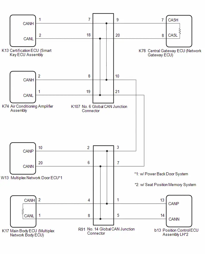
CAUTION / NOTICE / HINT
CAUTION:
When performing the confirmation driving pattern, obey all speed limits and traffic laws.
NOTICE:
-
Because the order of diagnosis is important to allow correct diagnosis, make sure to begin troubleshooting using How to Proceed with Troubleshooting when CAN communication system related DTCs are output.
Click here

- Before measuring the resistance of the CAN bus, turn the ignition switch off and leave the Toyota Prius vehicle for 1 minute or more without operating the key or any switches, or opening or closing the doors. After that, disconnect the cable from the negative (-) auxiliary battery terminal and leave the vehicle for 1 minute or more before measuring the resistance.
-
After the ignition switch is turned off, there may be a waiting time before disconnecting the negative (-) auxiliary battery terminal.
Click here

-
When disconnecting and reconnecting the auxiliary battery.
HINT:
When disconnecting and reconnecting the auxiliary battery, there is an automatic learning function that completes learning when the respective system is used.
Click here


-
Some parts must be initialized and set when replacing or removing and installing parts.
Click here


-
After performing repairs, perform the DTC check procedure and confirm that the DTCs are not output again.
DTC check procedure: Turn the ignition switch to ON and wait for 1 minute or more. Then operate the suspected malfunctioning system and drive the Toyota Prius vehicle at 60 km/h (37 mph) or more for 5 minutes or more.
-
After the repair, perform the CAN bus check and check that all the ECUs and sensors connected to the CAN communication system are displayed as normal.
Click here

-
Before replacing the main body ECU (multiplex network body ECU) or certification ECU (smart key ECU assembly), refer to Registration.
Click here

- When disconnecting a wire harness of any component connected to the supply power of the integrated capacitor (integration control supply) or when removing the integrated capacitor (integration control supply), make sure to wait 5 minutes or more after turning the ignition switch off for self-diagnosis to complete and the voltage of the integrated capacitor (integration control supply) to discharge.
HINT:
- Before disconnecting related connectors for inspection, push in on each connector body to check that the connector is not loose or disconnected.
- When a connector is disconnected, check that the terminals and connector body are not cracked, deformed or corroded.
PROCEDURE
| 1. | CHECK FOR OPEN IN CAN MAIN BUS LINES |
(a) Disconnect the cable from the negative (-) auxiliary battery terminal.
| (b) Measure the resistance according to the value(s) in the table below. Standard Resistance:  Click Location & Routing(K78) Click Connector(K78) Click Location & Routing(K78) Click Connector(K78)
|
|
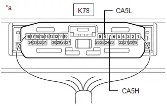
| NG |

| GO TO STEP 53 |
|

| 2. | CHECK FOR SHORT IN CAN BUS LINES |
| (a) Measure the resistance according to the value(s) in the table below. Standard Resistance:  Click Location & Routing(K78) Click Connector(K78) Click Location & Routing(K78) Click Connector(K78)
|
|

| NG |

| GO TO STEP 37 |
|

| 3. | CHECK FOR SHORT TO B IN CAN BUS LINE |
(a) Measure the resistance according to the value(s) in the table below.
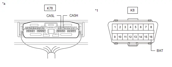
| *1 | DLC3 | - | - |
| *a | Component with harness connected (Central Gateway ECU (Network Gateway ECU)) | - | - |
Standard Resistance:
 Click Location & Routing(K78,K8) Click Connector(K78) Click Connector(K8)
 | Tester Connection | Condition | Specified Condition |
|---|---|---|
| K78-7 (CA5H) - K8-16 (BAT) | Cable disconnected from negative (-) auxiliary battery terminal | 6 kΩ or higher |
| K78-8 (CA5L) - K8-16 (BAT) |
| NG |

| GO TO STEP 21 |
|

| 4. | CHECK FOR SHORT TO GND IN CAN BUS LINE |
(a) Measure the resistance according to the value(s) in the table below.
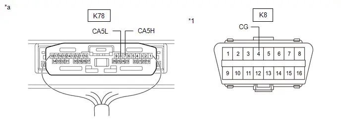
| *1 | DLC3 | - | - |
| *a | Component with harness connected (Central Gateway ECU (Network Gateway ECU)) | - | - |
Standard Resistance:
 Click Location & Routing(K78,K8) Click Connector(K78) Click Connector(K8)
 | Tester Connection | Condition | Specified Condition |
|---|---|---|
| K78-7 (CA5H) - K8-4 (CG) | Cable disconnected from negative (-) auxiliary battery terminal | 200 Ω or higher |
| K78-8 (CA5L) - K8-4 (CG) |
| OK |

| REPLACE CENTRAL GATEWAY ECU (NETWORK GATEWAY ECU) |
|

| 5. | CHECK FOR SHORT TO GND IN CAN BUS LINE (NO. 6 GLOBAL CAN JUNCTION CONNECTOR - CENTRAL GATEWAY ECU (NETWORK GATEWAY ECU)) |
(a) Disconnect the K107 No. 6 global CAN junction connector.
(b) Measure the resistance according to the value(s) in the table below.
Standard Resistance:
 Click Location & Routing(K107,K8) Click Connector(K107) Click Connector(K8)
 | Tester Connection | Condition | Specified Condition |
|---|---|---|
| K107-9 (CANH) - K8-4 (CG) | Cable disconnected from negative (-) auxiliary battery terminal | 200 Ω or higher |
| K107-20 (CANL) - K8-4 (CG) |
| NG |

| GO TO STEP 9 |
|

| 6. | CHECK FOR SHORT TO GND IN CAN BUS LINE (NO. 6 GLOBAL CAN JUNCTION CONNECTOR - NO. 14 GLOBAL CAN JUNCTION CONNECTOR) |
(a) Measure the resistance according to the value(s) in the table below.
Standard Resistance:
 Click Location & Routing(K107,K8) Click Connector(K107) Click Connector(K8)
 | Tester Connection | Condition | Specified Condition |
|---|---|---|
| K107-10 (CANH) - K8-4 (CG) | Cable disconnected from negative (-) auxiliary battery terminal | 200 Ω or higher |
| K107-21 (CANL) - K8-4 (CG) |
| NG |

| GO TO STEP 12 |
|

| 7. | CHECK FOR SHORT TO GND IN CAN BUS LINE (NO. 6 GLOBAL CAN JUNCTION CONNECTOR - AIR CONDITIONING AMPLIFIER ASSEMBLY) |
(a) Measure the resistance according to the value(s) in the table below.
Standard Resistance:
 Click Location & Routing(K107,K8) Click Connector(K107) Click Connector(K8)
 | Tester Connection | Condition | Specified Condition |
|---|---|---|
| K107-8 (CANH) - K8-4 (CG) | Cable disconnected from negative (-) auxiliary battery terminal | 200 Ω or higher |
| K107-19 (CANL) - K8-4 (CG) |
| NG |

| GO TO STEP 10 |
|

| 8. | CHECK FOR SHORT TO GND IN CAN BUS LINE (NO. 6 GLOBAL CAN JUNCTION CONNECTOR - CERTIFICATION ECU (SMART KEY ECU ASSEMBLY)) |
(a) Measure the resistance according to the value(s) in the table below.
Standard Resistance:
 Click Location & Routing(K107,K8) Click Connector(K107) Click Connector(K8)
 | Tester Connection | Condition | Specified Condition |
|---|---|---|
| K107-7 (CANH) - K8-4 (CG) | Cable disconnected from negative (-) auxiliary battery terminal | 200 Ω or higher |
| K107-18 (CANL) - K8-4 (CG) |
| OK |

| REPLACE NO. 6 GLOBAL CAN JUNCTION CONNECTOR |
| NG |

| GO TO STEP 11 |
| 9. | CHECK FOR SHORT TO GND IN CAN BUS LINE (NO. 6 GLOBAL CAN JUNCTION CONNECTOR - CENTRAL GATEWAY ECU (NETWORK GATEWAY ECU)) |
(a) Disconnect the K78 central gateway ECU (network gateway ECU) connector.
(b) Measure the resistance according to the value(s) in the table below.
Standard Resistance:
 Click Location & Routing(K107,K8) Click Connector(K107) Click Connector(K8)
 | Tester Connection | Condition | Specified Condition |
|---|---|---|
| K107-9 (CANH) - K8-4 (CG) | Cable disconnected from negative (-) auxiliary battery terminal | 200 Ω or higher |
| K107-20 (CANL) - K8-4 (CG) |
| OK |

| REPLACE CENTRAL GATEWAY ECU (NETWORK GATEWAY ECU) |
| NG |

| REPAIR OR REPLACE CAN MAIN BUS LINE OR CONNECTOR (NO. 6 GLOBAL CAN JUNCTION CONNECTOR - CENTRAL GATEWAY ECU (NETWORK GATEWAY ECU)) |
| 10. | CHECK FOR SHORT TO GND IN CAN BUS LINE (NO. 6 GLOBAL CAN JUNCTION CONNECTOR - AIR CONDITIONING AMPLIFIER ASSEMBLY) |
(a) Disconnect the K74 air conditioning amplifier assembly connector.
(b) Measure the resistance according to the value(s) in the table below.
Standard Resistance:
 Click Location & Routing(K107,K8) Click Connector(K107) Click Connector(K8)
 | Tester Connection | Condition | Specified Condition |
|---|---|---|
| K107-8 (CANH) - K8-4 (CG) | Cable disconnected from negative (-) auxiliary battery terminal | 200 Ω or higher |
| K107-19 (CANL) - K8-4 (CG) |
| OK |

| REPLACE AIR CONDITIONING AMPLIFIER ASSEMBLY |
| NG |

| REPAIR OR REPLACE CAN BRANCH LINE OR CONNECTOR (NO. 6 GLOBAL CAN JUNCTION CONNECTOR - AIR CONDITIONING AMPLIFIER ASSEMBLY) |
| 11. | CHECK FOR SHORT TO GND IN CAN BUS LINE (NO. 6 GLOBAL CAN JUNCTION CONNECTOR - CERTIFICATION ECU (SMART KEY ECU ASSEMBLY)) |
(a) Disconnect the K13 certification ECU (smart key ECU assembly) connector.
(b) Measure the resistance according to the value(s) in the table below.
Standard Resistance:
 Click Location & Routing(K107,K8) Click Connector(K107) Click Connector(K8)
 | Tester Connection | Condition | Specified Condition |
|---|---|---|
| K107-7 (CANH) - K8-4 (CG) | Cable disconnected from negative (-) auxiliary battery terminal | 200 Ω or higher |
| K107-18 (CANL) - K8-4 (CG) |
| OK |

| REPLACE CERTIFICATION ECU (SMART KEY ECU ASSEMBLY)
|


| NG |

| REPAIR OR REPLACE CAN BRANCH LINE OR CONNECTOR (NO. 6 GLOBAL CAN JUNCTION CONNECTOR - CERTIFICATION ECU (SMART KEY ECU ASSEMBLY)) |
| 12. | CHECK FOR SHORT TO GND IN CAN BUS LINE (NO. 14 GLOBAL CAN JUNCTION CONNECTOR - NO. 6 GLOBAL CAN JUNCTION CONNECTOR) |
(a) Disconnect the R91 No. 14 global CAN junction connector.
(b) Measure the resistance according to the value(s) in the table below.
Standard Resistance:
 Click Location & Routing(R91,K8) Click Connector(R91) Click Connector(K8)
 | Tester Connection | Condition | Specified Condition |
|---|---|---|
| R91-3 (CANH) - K8-4 (CG) | Cable disconnected from negative (-) auxiliary battery terminal | 200 Ω or higher |
| R91-7 (CANL) - K8-4 (CG) |
| NG |

| REPAIR OR REPLACE CAN MAIN BUS LINE OR CONNECTOR (NO. 14 GLOBAL CAN JUNCTION CONNECTOR - NO. 6 GLOBAL CAN JUNCTION CONNECTOR) |
|

| 13. | CHECK FOR SHORT TO GND IN CAN BUS LINE (NO. 14 GLOBAL CAN JUNCTION CONNECTOR - MAIN BODY ECU (MULTIPLEX NETWORK BODY ECU)) |
(a) Measure the resistance according to the value(s) in the table below.
Standard Resistance:
 Click Location & Routing(R91,K8) Click Connector(R91) Click Connector(K8)
 | Tester Connection | Condition | Specified Condition |
|---|---|---|
| R91-4 (CANH) - K8-4 (CG) | Cable disconnected from negative (-) auxiliary battery terminal | 200 Ω or higher |
| R91-8 (CANL) - K8-4 (CG) |
| NG |

| GO TO STEP 18 |
|

| 14. | CHECK Toyota Prius Vehicle TYPE |
(a) Check vehicle type.
| Result | Proceed to |
|---|---|
| w/ Seat Position Memory System | A |
| w/o Seat Position Memory System | B |
| B |

| GO TO STEP 16 |
|

| 15. | CHECK FOR SHORT TO GND IN CAN BUS LINE (NO. 14 GLOBAL CAN JUNCTION CONNECTOR - POSITION CONTROL ECU ASSEMBLY LH) |
(a) Measure the resistance according to the value(s) in the table below.
Standard Resistance:
 Click Location & Routing(R91,K8) Click Connector(R91) Click Connector(K8)
 | Tester Connection | Condition | Specified Condition |
|---|---|---|
| R91-1 (CANH) - K8-4 (CG) | Cable disconnected from negative (-) auxiliary battery terminal | 200 Ω or higher |
| R91-5 (CANL) - K8-4 (CG) |
| NG |

| GO TO STEP 19 |
|

| 16. | CHECK Toyota Prius Vehicle TYPE |
(a) Check vehicle type.
| Result | Proceed to |
|---|---|
| w/ Power Back Door System | A |
| w/o Power Back Door System | B |
| B |

| REPLACE NO. 14 GLOBAL CAN JUNCTION CONNECTOR |
|

| 17. | CHECK FOR SHORT TO GND IN CAN BUS LINE (NO. 14 GLOBAL CAN JUNCTION CONNECTOR - MULTIPLEX NETWORK DOOR ECU) |
(a) Measure the resistance according to the value(s) in the table below.
Standard Resistance:
 Click Location & Routing(R91,K8) Click Connector(R91) Click Connector(K8)
 | Tester Connection | Condition | Specified Condition |
|---|---|---|
| R91-2 (CANH) - K8-4 (CG) | Cable disconnected from negative (-) auxiliary battery terminal | 200 Ω or higher |
| R91-6 (CANL) - K8-4 (CG) |
| OK |

| REPLACE NO. 14 GLOBAL CAN JUNCTION CONNECTOR |
| NG |

| GO TO STEP 20 |
| 18. | CHECK FOR SHORT TO GND IN CAN BUS LINE (NO. 14 GLOBAL CAN JUNCTION CONNECTOR - MAIN BODY ECU (MULTIPLEX NETWORK BODY ECU)) |
(a) Disconnect the K17 main body ECU (multiplex network body ECU) connector.
(b) Measure the resistance according to the value(s) in the table below.
Standard Resistance:
 Click Location & Routing(R91,K8) Click Connector(R91) Click Connector(K8)
 | Tester Connection | Condition | Specified Condition |
|---|---|---|
| R91-4 (CANH) - K8-4 (CG) | Cable disconnected from negative (-) auxiliary battery terminal | 200 Ω or higher |
| R91-8 (CANL) - K8-4 (CG) |
| OK |

| REPLACE MAIN BODY ECU (MULTIPLEX NETWORK BODY ECU)
|


| NG |

| REPAIR OR REPLACE CAN MAIN BUS LINE OR CONNECTOR (NO. 14 GLOBAL CAN JUNCTION CONNECTOR - MAIN BODY ECU (MULTIPLEX NETWORK BODY ECU)) |
| 19. | CHECK FOR SHORT TO GND IN CAN BUS LINE (NO. 14 GLOBAL CAN JUNCTION CONNECTOR - POSITION CONTROL ECU ASSEMBLY LH) |
(a) Disconnect the b13 position control ECU assembly LH connector.
(b) Measure the resistance according to the value(s) in the table below.
Standard Resistance:
 Click Location & Routing(R91,K8) Click Connector(R91) Click Connector(K8)
 | Tester Connection | Condition | Specified Condition |
|---|---|---|
| R91-1 (CANH) - K8-4 (CG) | Cable disconnected from negative (-) auxiliary battery terminal | 200 Ω or higher |
| R91-5 (CANL) - K8-4 (CG) |
| OK |

| REPLACE POSITION CONTROL ECU ASSEMBLY LH
|


| NG |

| REPAIR OR REPLACE CAN BRANCH LINE OR CONNECTOR (NO. 14 GLOBAL CAN JUNCTION CONNECTOR - POSITION CONTROL ECU ASSEMBLY LH) |
| 20. | CHECK FOR SHORT TO GND IN CAN BUS LINE (NO. 14 GLOBAL CAN JUNCTION CONNECTOR - MULTIPLEX NETWORK DOOR ECU) |
(a) Disconnect the W13 multiplex network door ECU connector.
(b) Measure the resistance according to the value(s) in the table below.
Standard Resistance:
 Click Location & Routing(R91,K8) Click Connector(R91) Click Connector(K8)
 | Tester Connection | Condition | Specified Condition |
|---|---|---|
| R91-2 (CANH) - K8-4 (CG) | Cable disconnected from negative (-) auxiliary battery terminal | 200 Ω or higher |
| R91-6 (CANL) - K8-4 (CG) |
| OK |

| REPLACE MULTIPLEX NETWORK DOOR ECU |
| NG |

| REPAIR OR REPLACE CAN BRANCH LINE OR CONNECTOR (NO. 14 GLOBAL CAN JUNCTION CONNECTOR - MULTIPLEX NETWORK DOOR ECU) |
| 21. | CHECK FOR SHORT TO B IN CAN BUS LINE (NO. 6 GLOBAL CAN JUNCTION CONNECTOR - CENTRAL GATEWAY ECU (NETWORK GATEWAY ECU)) |
(a) Disconnect the K107 No. 6 global CAN junction connector.
(b) Measure the resistance according to the value(s) in the table below.
Standard Resistance:
 Click Location & Routing(K107,K8) Click Connector(K107) Click Connector(K8)
 | Tester Connection | Condition | Specified Condition |
|---|---|---|
| K107-9 (CANH) - K8-16 (BAT) | Cable disconnected from negative (-) auxiliary battery terminal | 6 kΩ or higher |
| K107-20 (CANL) - K8-16 (BAT) |
| NG |

| GO TO STEP 25 |
|

| 22. | CHECK FOR SHORT TO B IN CAN BUS LINE (NO. 6 GLOBAL CAN JUNCTION CONNECTOR - NO. 14 GLOBAL CAN JUNCTION CONNECTOR) |
(a) Measure the resistance according to the value(s) in the table below.
Standard Resistance:
 Click Location & Routing(K107,K8) Click Connector(K107) Click Connector(K8)
 | Tester Connection | Condition | Specified Condition |
|---|---|---|
| K107-10 (CANH) - K8-16 (BAT) | Cable disconnected from negative (-) auxiliary battery terminal | 6 kΩ or higher |
| K107-21 (CANL) - K8-16 (BAT) |
| NG |

| GO TO STEP 28 |
|

| 23. | CHECK FOR SHORT TO B IN CAN BUS LINE (NO. 6 GLOBAL CAN JUNCTION CONNECTOR - AIR CONDITIONING AMPLIFIER ASSEMBLY) |
(a) Measure the resistance according to the value(s) in the table below.
Standard Resistance:
 Click Location & Routing(K107,K8) Click Connector(K107) Click Connector(K8)
 | Tester Connection | Condition | Specified Condition |
|---|---|---|
| K107-8 (CANH) - K8-16 (BAT) | Cable disconnected from negative (-) auxiliary battery terminal | 6 kΩ or higher |
| K107-19 (CANL) - K8-16 (BAT) |
| NG |

| GO TO STEP 26 |
|

| 24. | CHECK FOR SHORT TO B IN CAN BUS LINE (NO. 6 GLOBAL CAN JUNCTION CONNECTOR - CERTIFICATION ECU (SMART KEY ECU ASSEMBLY)) |
(a) Measure the resistance according to the value(s) in the table below.
Standard Resistance:
 Click Location & Routing(K107,K8) Click Connector(K107) Click Connector(K8)
 | Tester Connection | Condition | Specified Condition |
|---|---|---|
| K107-7 (CANH) - K8-16 (BAT) | Cable disconnected from negative (-) auxiliary battery terminal | 6 kΩ or higher |
| K107-18 (CANL) - K8-16 (BAT) |
| OK |

| REPLACE NO. 6 GLOBAL CAN JUNCTION CONNECTOR |
| NG |

| GO TO STEP 27 |
| 25. | CHECK FOR SHORT TO B IN CAN BUS LINE (NO. 6 GLOBAL CAN JUNCTION CONNECTOR - CENTRAL GATEWAY ECU (NETWORK GATEWAY ECU)) |
(a) Disconnect the K78 central gateway ECU (network gateway ECU) connector.
(b) Measure the resistance according to the value(s) in the table below.
Standard Resistance:
 Click Location & Routing(K107,K8) Click Connector(K107) Click Connector(K8)
 | Tester Connection | Condition | Specified Condition |
|---|---|---|
| K107-9 (CANH) - K8-16 (BAT) | Cable disconnected from negative (-) auxiliary battery terminal | 6 kΩ or higher |
| K107-20 (CANL) - K8-16 (BAT) |
| OK |

| REPLACE CENTRAL GATEWAY ECU (NETWORK GATEWAY ECU) |
| NG |

| REPAIR OR REPLACE CAN MAIN BUS LINE OR CONNECTOR (NO. 6 GLOBAL CAN JUNCTION CONNECTOR - CENTRAL GATEWAY ECU (NETWORK GATEWAY ECU)) |
| 26. | CHECK FOR SHORT TO B IN CAN BUS LINE (NO. 6 GLOBAL CAN JUNCTION CONNECTOR - AIR CONDITIONING AMPLIFIER ASSEMBLY) |
(a) Disconnect the K74 air conditioning amplifier assembly connector.
(b) Measure the resistance according to the value(s) in the table below.
Standard Resistance:
 Click Location & Routing(K107,K8) Click Connector(K107) Click Connector(K8)
 | Tester Connection | Condition | Specified Condition |
|---|---|---|
| K107-8 (CANH) - K8-16 (BAT) | Cable disconnected from negative (-) auxiliary battery terminal | 6 kΩ or higher |
| K107-19 (CANL) - K8-16 (BAT) |
| OK |

| REPLACE AIR CONDITIONING AMPLIFIER ASSEMBLY |
| NG |

| REPAIR OR REPLACE CAN BRANCH LINE OR CONNECTOR (NO. 6 GLOBAL CAN JUNCTION CONNECTOR - AIR CONDITIONING AMPLIFIER ASSEMBLY) |
| 27. | CHECK FOR SHORT TO B IN CAN BUS LINE (NO. 6 GLOBAL CAN JUNCTION CONNECTOR - CERTIFICATION ECU (SMART KEY ECU ASSEMBLY)) |
(a) Disconnect the K13 certification ECU (smart key ECU assembly) connector.
(b) Measure the resistance according to the value(s) in the table below.
Standard Resistance:
 Click Location & Routing(K107,K8) Click Connector(K107) Click Connector(K8)
 | Tester Connection | Condition | Specified Condition |
|---|---|---|
| K107-7 (CANH) - K8-16 (BAT) | Cable disconnected from negative (-) auxiliary battery terminal | 6 kΩ or higher |
| K107-18 (CANL) - K8-16 (BAT) |
| OK |

| REPLACE CERTIFICATION ECU (SMART KEY ECU ASSEMBLY)
|


| NG |

| REPAIR OR REPLACE CAN BRANCH LINE OR CONNECTOR (NO. 6 GLOBAL CAN JUNCTION CONNECTOR - CERTIFICATION ECU (SMART KEY ECU ASSEMBLY)) |
| 28. | CHECK FOR SHORT TO B IN CAN BUS LINE (NO. 14 GLOBAL CAN JUNCTION CONNECTOR - NO. 6 GLOBAL CAN JUNCTION CONNECTOR) |
(a) Disconnect the R91 No. 14 global CAN junction connector.
(b) Measure the resistance according to the value(s) in the table below.
Standard Resistance:
 Click Location & Routing(R91,K8) Click Connector(R91) Click Connector(K8)
 | Tester Connection | Condition | Specified Condition |
|---|---|---|
| R91-3 (CANH) - K8-16 (BAT) | Cable disconnected from negative (-) auxiliary battery terminal | 6 kΩ or higher |
| R91-7 (CANL) - K8-16 (BAT) |
| NG |

| REPAIR OR REPLACE CAN MAIN BUS LINE OR CONNECTOR (NO. 14 GLOBAL CAN JUNCTION CONNECTOR - NO. 6 GLOBAL CAN JUNCTION CONNECTOR) |
|

| 29. | CHECK FOR SHORT TO B IN CAN BUS LINE (NO. 14 GLOBAL CAN JUNCTION CONNECTOR - MAIN BODY ECU (MULTIPLEX NETWORK BODY ECU)) |
(a) Measure the resistance according to the value(s) in the table below.
Standard Resistance:
 Click Location & Routing(R91,K8) Click Connector(R91) Click Connector(K8)
 | Tester Connection | Condition | Specified Condition |
|---|---|---|
| R91-4 (CANH) - K8-16 (BAT) | Cable disconnected from negative (-) auxiliary battery terminal | 6 kΩ or higher |
| R91-8 (CANL) - K8-16 (BAT) |
| NG |

| GO TO STEP 34 |
|

| 30. | CHECK Toyota Prius Vehicle TYPE |
(a) Check vehicle type.
| Result | Proceed to |
|---|---|
| w/ Seat Position Memory System | A |
| w/o Seat Position Memory System | B |
| B |

| GO TO STEP 32 |
|

| 31. | CHECK FOR SHORT TO B IN CAN BUS LINE (NO. 14 GLOBAL CAN JUNCTION CONNECTOR - POSITION CONTROL ECU ASSEMBLY LH) |
(a) Measure the resistance according to the value(s) in the table below.
Standard Resistance:
 Click Location & Routing(R91,K8) Click Connector(R91) Click Connector(K8)
 | Tester Connection | Condition | Specified Condition |
|---|---|---|
| R91-1 (CANH) - K8-16 (BAT) | Cable disconnected from negative (-) auxiliary battery terminal | 6 kΩ or higher |
| R91-5 (CANL) - K8-16 (BAT) |
| NG |

| GO TO STEP 35 |
|

| 32. | CHECK Toyota Prius Vehicle TYPE |
(a) Check vehicle type.
| Result | Proceed to |
|---|---|
| w/ Power Back Door System | A |
| w/o Power Back Door System | B |
| B |

| REPLACE NO. 14 GLOBAL CAN JUNCTION CONNECTOR |
|

| 33. | CHECK FOR SHORT TO B IN CAN BUS LINE (NO. 14 GLOBAL CAN JUNCTION CONNECTOR - MULTIPLEX NETWORK DOOR ECU) |
(a) Measure the resistance according to the value(s) in the table below.
Standard Resistance:
 Click Location & Routing(R91,K8) Click Connector(R91) Click Connector(K8)
 | Tester Connection | Condition | Specified Condition |
|---|---|---|
| R91-2 (CANH) - K8-16 (BAT) | Cable disconnected from negative (-) auxiliary battery terminal | 6 kΩ or higher |
| R91-6 (CANL) - K8-16 (BAT) |
| OK |

| REPLACE NO. 14 GLOBAL CAN JUNCTION CONNECTOR |
| NG |

| GO TO STEP 36 |
| 34. | CHECK FOR SHORT TO B IN CAN BUS LINE (NO. 14 GLOBAL CAN JUNCTION CONNECTOR - MAIN BODY ECU (MULTIPLEX NETWORK BODY ECU)) |
(a) Disconnect the K17 main body ECU (multiplex network body ECU) connector.
(b) Measure the resistance according to the value(s) in the table below.
Standard Resistance:
 Click Location & Routing(R91,K8) Click Connector(R91) Click Connector(K8)
 | Tester Connection | Condition | Specified Condition |
|---|---|---|
| R91-4 (CANH) - K8-16 (BAT) | Cable disconnected from negative (-) auxiliary battery terminal | 6 kΩ or higher |
| R91-8 (CANL) - K8-16 (BAT) |
| OK |

| REPLACE MAIN BODY ECU (MULTIPLEX NETWORK BODY ECU)
|


| NG |

| REPAIR OR REPLACE CAN MAIN BUS LINE OR CONNECTOR (NO. 14 GLOBAL CAN JUNCTION CONNECTOR - MAIN BODY ECU (MULTIPLEX NETWORK BODY ECU)) |
| 35. | CHECK FOR SHORT TO B IN CAN BUS LINE (NO. 14 GLOBAL CAN JUNCTION CONNECTOR - POSITION CONTROL ECU ASSEMBLY LH) |
(a) Disconnect the b13 position control ECU assembly LH connector.
(b) Measure the resistance according to the value(s) in the table below.
Standard Resistance:
 Click Location & Routing(R91,K8) Click Connector(R91) Click Connector(K8)
 | Tester Connection | Condition | Specified Condition |
|---|---|---|
| R91-1 (CANH) - K8-16 (BAT) | Cable disconnected from negative (-) auxiliary battery terminal | 6 kΩ or higher |
| R91-5 (CANL) - K8-16 (BAT) |
| OK |

| REPLACE POSITION CONTROL ECU ASSEMBLY LH
|


| NG |

| REPAIR OR REPLACE CAN BRANCH LINE OR CONNECTOR (NO. 14 GLOBAL CAN JUNCTION CONNECTOR - POSITION CONTROL ECU ASSEMBLY LH) |
| 36. | CHECK FOR SHORT TO B IN CAN BUS LINE (NO. 14 GLOBAL CAN JUNCTION CONNECTOR - MULTIPLEX NETWORK DOOR ECU) |
(a) Disconnect the W13 multiplex network door ECU connector.
(b) Measure the resistance according to the value(s) in the table below.
Standard Resistance:
 Click Location & Routing(R91,K8) Click Connector(R91) Click Connector(K8)
 | Tester Connection | Condition | Specified Condition |
|---|---|---|
| R91-2 (CANH) - K8-16 (BAT) | Cable disconnected from negative (-) auxiliary battery terminal | 6 kΩ or higher |
| R91-6 (CANL) - K8-16 (BAT) |
| OK |

| REPLACE MULTIPLEX NETWORK DOOR ECU |
| NG |

| REPAIR OR REPLACE CAN BRANCH LINE OR CONNECTOR (NO. 14 GLOBAL CAN JUNCTION CONNECTOR - MULTIPLEX NETWORK DOOR ECU) |
| 37. | CHECK FOR SHORT IN CAN BUS LINES (NO. 6 GLOBAL CAN JUNCTION CONNECTOR - CENTRAL GATEWAY ECU (NETWORK GATEWAY ECU)) |
(a) Disconnect the K107 No. 6 global CAN junction connector.
(b) Measure the resistance according to the value(s) in the table below.
Standard Resistance:
 Click Location & Routing(K107) Click Connector(K107)
 | Tester Connection | Condition | Specified Condition |
|---|---|---|
| K107-9 (CANH) - K107-20 (CANL) | Cable disconnected from negative (-) auxiliary battery terminal | 108 to 132 Ω |
| NG |

| GO TO STEP 41 |
|

| 38. | CHECK FOR SHORT IN CAN BUS LINES (NO. 6 GLOBAL CAN JUNCTION CONNECTOR - NO. 14 GLOBAL CAN JUNCTION CONNECTOR) |
(a) Measure the resistance according to the value(s) in the table below.
Standard Resistance:
 Click Location & Routing(K107) Click Connector(K107)
 | Tester Connection | Condition | Specified Condition |
|---|---|---|
| K107-10 (CANH) - K107-21 (CANL) | Cable disconnected from negative (-) auxiliary battery terminal | 108 to 132 Ω |
| NG |

| GO TO STEP 44 |
|

| 39. | CHECK FOR SHORT IN CAN BUS LINES (NO. 6 GLOBAL CAN JUNCTION CONNECTOR - AIR CONDITIONING AMPLIFIER ASSEMBLY) |
(a) Measure the resistance according to the value(s) in the table below.
Standard Resistance:
 Click Location & Routing(K107) Click Connector(K107)
 | Tester Connection | Condition | Specified Condition |
|---|---|---|
| K107-8 (CANH) - K107-19 (CANL) | Cable disconnected from negative (-) auxiliary battery terminal | 200 Ω or higher |
| NG |

| GO TO STEP 42 |
|

| 40. | CHECK FOR SHORT IN CAN BUS LINES (NO. 6 GLOBAL CAN JUNCTION CONNECTOR - CERTIFICATION ECU (SMART KEY ECU ASSEMBLY)) |
(a) Measure the resistance according to the value(s) in the table below.
Standard Resistance:
 Click Location & Routing(K107) Click Connector(K107)
 | Tester Connection | Condition | Specified Condition |
|---|---|---|
| K107-7 (CANH) - K107-18 (CANL) | Cable disconnected from negative (-) auxiliary battery terminal | 200 Ω or higher |
| OK |

| REPLACE NO. 6 GLOBAL CAN JUNCTION CONNECTOR |
| NG |

| GO TO STEP 43 |
| 41. | CHECK FOR SHORT IN CAN BUS LINES (NO. 6 GLOBAL CAN JUNCTION CONNECTOR - CENTRAL GATEWAY ECU (NETWORK GATEWAY ECU)) |
(a) Disconnect the K78 central gateway ECU (network gateway ECU) connector.
(b) Measure the resistance according to the value(s) in the table below.
Standard Resistance:
 Click Location & Routing(K107) Click Connector(K107)
 | Tester Connection | Condition | Specified Condition |
|---|---|---|
| K107-9 (CANH) - K107-20 (CANL) | Cable disconnected from negative (-) auxiliary battery terminal | 1 MΩ or higher |
| OK |

| REPLACE CENTRAL GATEWAY ECU (NETWORK GATEWAY ECU) |
| NG |

| REPAIR OR REPLACE CAN MAIN BUS LINES OR CONNECTOR (NO. 6 GLOBAL CAN JUNCTION CONNECTOR - CENTRAL GATEWAY ECU (NETWORK GATEWAY ECU)) |
| 42. | CHECK FOR SHORT IN CAN BUS LINES (NO. 6 GLOBAL CAN JUNCTION CONNECTOR - AIR CONDITIONING AMPLIFIER ASSEMBLY) |
(a) Disconnect the K74 air conditioning amplifier assembly connector.
(b) Measure the resistance according to the value(s) in the table below.
Standard Resistance:
 Click Location & Routing(K107) Click Connector(K107)
 | Tester Connection | Condition | Specified Condition |
|---|---|---|
| K107-8 (CANH) - K107-19 (CANL) | Cable disconnected from negative (-) auxiliary battery terminal | 1 MΩ or higher |
| OK |

| REPLACE AIR CONDITIONING AMPLIFIER ASSEMBLY |
| NG |

| REPAIR OR REPLACE CAN BRANCH LINES OR CONNECTOR (NO. 6 GLOBAL CAN JUNCTION CONNECTOR - AIR CONDITIONING AMPLIFIER ASSEMBLY) |
| 43. | CHECK FOR SHORT IN CAN BUS LINES (NO. 6 GLOBAL CAN JUNCTION CONNECTOR - CERTIFICATION ECU (SMART KEY ECU ASSEMBLY)) |
(a) Disconnect the K13 certification ECU (smart key ECU assembly) connector.
(b) Measure the resistance according to the value(s) in the table below.
Standard Resistance:
 Click Location & Routing(K107) Click Connector(K107)
 | Tester Connection | Condition | Specified Condition |
|---|---|---|
| K107-7 (CANH) - K107-18 (CANL) | Cable disconnected from negative (-) auxiliary battery terminal | 1 MΩ or higher |
| OK |

| REPLACE CERTIFICATION ECU (SMART KEY ECU ASSEMBLY)
|


| NG |

| REPAIR OR REPLACE CAN BRANCH LINES OR CONNECTOR (NO. 6 GLOBAL CAN JUNCTION CONNECTOR - CERTIFICATION ECU (SMART KEY ECU ASSEMBLY)) |
| 44. | CHECK FOR SHORT IN CAN BUS LINES (NO. 14 GLOBAL CAN JUNCTION CONNECTOR - NO. 6 GLOBAL CAN JUNCTION CONNECTOR) |
(a) Reconnect the K107 No. 6 global CAN junction connector.
(b) Disconnect the R91 No. 14 global CAN junction connector.
(c) Measure the resistance according to the value(s) in the table below.
Standard Resistance:
 Click Location & Routing(R91) Click Connector(R91)
 | Tester Connection | Condition | Specified Condition |
|---|---|---|
| R91-3 (CANH) - R91-7 (CANL) | Cable disconnected from negative (-) auxiliary battery terminal | 108 to 132 Ω |
| NG |

| REPAIR OR REPLACE CAN MAIN BUS LINES OR CONNECTOR (NO. 14 GLOBAL CAN JUNCTION CONNECTOR - NO. 6 GLOBAL CAN JUNCTION CONNECTOR) |
|

| 45. | CHECK FOR SHORT IN CAN BUS LINES (NO. 14 GLOBAL CAN JUNCTION CONNECTOR - MAIN BODY ECU (MULTIPLEX NETWORK BODY ECU)) |
(a) Measure the resistance according to the value(s) in the table below.
Standard Resistance:
 Click Location & Routing(R91) Click Connector(R91)
 | Tester Connection | Condition | Specified Condition |
|---|---|---|
| R91-4 (CANH) - R91-8 (CANL) | Cable disconnected from negative (-) auxiliary battery terminal | 108 to 132 Ω |
| NG |

| GO TO STEP 50 |
|

| 46. | CHECK Toyota Prius Vehicle TYPE |
(a) Check vehicle type.
| Result | Proceed to |
|---|---|
| w/ Seat Position Memory System | A |
| w/o Seat Position Memory System | B |
| B |

| GO TO STEP 48 |
|

| 47. | CHECK FOR SHORT IN CAN BUS LINES (NO. 14 GLOBAL CAN JUNCTION CONNECTOR - POSITION CONTROL ECU ASSEMBLY LH) |
(a) Measure the resistance according to the value(s) in the table below.
Standard Resistance:
 Click Location & Routing(R91) Click Connector(R91)
 | Tester Connection | Condition | Specified Condition |
|---|---|---|
| R91-1 (CANH) - R91-5 (CANL) | Cable disconnected from negative (-) auxiliary battery terminal | 200 Ω or higher |
| NG |

| GO TO STEP 51 |
|

| 48. | CHECK Toyota Prius Vehicle TYPE |
(a) Check vehicle type.
| Result | Proceed to |
|---|---|
| w/ Power Back Door System | A |
| w/o Power Back Door System | B |
| B |

| REPLACE NO. 14 GLOBAL CAN JUNCTION CONNECTOR |
|

| 49. | CHECK FOR SHORT IN CAN BUS LINES (NO. 14 GLOBAL CAN JUNCTION CONNECTOR - MULTIPLEX NETWORK DOOR ECU) |
(a) Measure the resistance according to the value(s) in the table below.
Standard Resistance:
 Click Location & Routing(R91) Click Connector(R91)
 | Tester Connection | Condition | Specified Condition |
|---|---|---|
| R91-2 (CANH) - R91-6 (CANL) | Cable disconnected from negative (-) auxiliary battery terminal | 200 Ω or higher |
| OK |

| REPLACE NO. 14 GLOBAL CAN JUNCTION CONNECTOR |
| NG |

| GO TO STEP 52 |
| 50. | CHECK FOR SHORT IN CAN BUS LINES (NO. 14 GLOBAL CAN JUNCTION CONNECTOR - MAIN BODY ECU (MULTIPLEX NETWORK BODY ECU)) |
(a) Disconnect the K17 main body ECU (multiplex network body ECU) connector.
(b) Measure the resistance according to the value(s) in the table below.
Standard Resistance:
 Click Location & Routing(R91) Click Connector(R91)
 | Tester Connection | Condition | Specified Condition |
|---|---|---|
| R91-4 (CANH) - R91-8 (CANL) | Cable disconnected from negative (-) auxiliary battery terminal | 1 MΩ or higher |
| OK |

| REPLACE MAIN BODY ECU (MULTIPLEX NETWORK BODY ECU)
|


| NG |

| REPAIR OR REPLACE CAN MAIN BUS LINES OR CONNECTOR (NO. 14 GLOBAL CAN JUNCTION CONNECTOR - MAIN BODY ECU (MULTIPLEX NETWORK BODY ECU)) |
| 51. | CHECK FOR SHORT IN CAN BUS LINES (NO. 14 GLOBAL CAN JUNCTION CONNECTOR - POSITION CONTROL ECU ASSEMBLY LH) |
(a) Disconnect the b13 position control ECU assembly LH connector.
(b) Measure the resistance according to the value(s) in the table below.
Standard Resistance:
 Click Location & Routing(R91) Click Connector(R91)
 | Tester Connection | Condition | Specified Condition |
|---|---|---|
| R91-1 (CANH) - R91-5 (CANL) | Cable disconnected from negative (-) auxiliary battery terminal | 1 MΩ or higher |
| OK |

| REPLACE POSITION CONTROL ECU ASSEMBLY LH
|


| NG |

| REPAIR OR REPLACE CAN BRANCH LINES OR CONNECTOR (NO. 14 GLOBAL CAN JUNCTION CONNECTOR - POSITION CONTROL ECU ASSEMBLY LH) |
| 52. | CHECK FOR SHORT IN CAN BUS LINES (NO. 14 GLOBAL CAN JUNCTION CONNECTOR - MULTIPLEX NETWORK DOOR ECU) |
(a) Disconnect the W13 multiplex network door ECU connector.
(b) Measure the resistance according to the value(s) in the table below.
Standard Resistance:
 Click Location & Routing(R91) Click Connector(R91)
 | Tester Connection | Condition | Specified Condition |
|---|---|---|
| R91-2 (CANH) - R91-6 (CANL) | Cable disconnected from negative (-) auxiliary battery terminal | 1 MΩ or higher |
| OK |

| REPLACE MULTIPLEX NETWORK DOOR ECU |
| NG |

| REPAIR OR REPLACE CAN BRANCH LINES OR CONNECTOR (NO. 14 GLOBAL CAN JUNCTION CONNECTOR - MULTIPLEX NETWORK DOOR ECU) |
| 53. | CHECK FOR OPEN IN CAN MAIN BUS LINES (CENTRAL GATEWAY ECU (NETWORK GATEWAY ECU)) |
(a) Disconnect the K78 central gateway ECU (network gateway ECU) connector.
(b) Measure the resistance according to the value(s) in the table below.
Standard Resistance:
 Click Location & Routing(K78) Click Connector(K78)
 | Tester Connection | Condition | Specified Condition |
|---|---|---|
| K78-7 (CA5H) - K78-8 (CA5L) | Cable disconnected from negative (-) auxiliary battery terminal | 108 to 132 Ω |
| OK |

| REPLACE CENTRAL GATEWAY ECU (NETWORK GATEWAY ECU) |
|

| 54. | CHECK FOR OPEN IN CAN MAIN BUS LINES (NO. 6 GLOBAL CAN JUNCTION CONNECTOR - CENTRAL GATEWAY ECU (NETWORK GATEWAY ECU)) |
(a) Reconnect the K78 central gateway ECU (network gateway ECU) connector.
(b) Disconnect the K107 No. 6 global CAN junction connector.
(c) Measure the resistance according to the value(s) in the table below.
Standard Resistance:
 Click Location & Routing(K107) Click Connector(K107)
 | Tester Connection | Condition | Specified Condition |
|---|---|---|
| K107-9 (CANH) - K107-20 (CANL) | Cable disconnected from negative (-) auxiliary battery terminal | 108 to 132 Ω |
| NG |

| REPAIR OR REPLACE CAN MAIN BUS LINES OR CONNECTOR (NO. 6 GLOBAL CAN JUNCTION CONNECTOR - CENTRAL GATEWAY ECU (NETWORK GATEWAY ECU)) |
|

| 55. | CHECK FOR OPEN IN CAN MAIN BUS LINES (NO. 6 GLOBAL CAN JUNCTION CONNECTOR - NO. 14 GLOBAL CAN JUNCTION CONNECTOR) |
(a) Measure the resistance according to the value(s) in the table below.
Standard Resistance:
 Click Location & Routing(K107) Click Connector(K107)
 | Tester Connection | Condition | Specified Condition |
|---|---|---|
| K107-10 (CANH) - K107-21 (CANL) | Cable disconnected from negative (-) auxiliary battery terminal | 108 to 132 Ω |
| OK |

| REPLACE NO. 6 GLOBAL CAN JUNCTION CONNECTOR |
|

| 56. | CHECK FOR OPEN IN CAN MAIN BUS LINES (NO. 14 GLOBAL CAN JUNCTION CONNECTOR - NO. 6 GLOBAL CAN JUNCTION CONNECTOR) |
(a) Reconnect the K107 No. 6 global CAN junction connector.
(b) Disconnect the R91 No. 14 global CAN junction connector.
(c) Measure the resistance according to the value(s) in the table below.
Standard Resistance:
 Click Location & Routing(R91) Click Connector(R91)
 | Tester Connection | Condition | Specified Condition |
|---|---|---|
| R91-3 (CANH) - R91-7 (CANL) | Cable disconnected from negative (-) auxiliary battery terminal | 108 to 132 Ω |
| NG |

| REPAIR OR REPLACE CAN MAIN BUS LINES OR CONNECTOR (NO. 14 GLOBAL CAN JUNCTION CONNECTOR - NO. 6 GLOBAL CAN JUNCTION CONNECTOR) |
|

| 57. | CHECK FOR OPEN IN CAN MAIN BUS LINES (NO. 14 GLOBAL CAN JUNCTION CONNECTOR - MAIN BODY ECU (MULTIPLEX NETWORK BODY ECU)) |
(a) Measure the resistance according to the value(s) in the table below.
Standard Resistance:
 Click Location & Routing(R91) Click Connector(R91)
 | Tester Connection | Condition | Specified Condition |
|---|---|---|
| R91-4 (CANH) - R91-8 (CANL) | Cable disconnected from negative (-) auxiliary battery terminal | 108 to 132 Ω |
| OK |

| REPLACE NO. 14 GLOBAL CAN JUNCTION CONNECTOR |
|

| 58. | CHECK FOR OPEN IN CAN MAIN BUS LINES (MAIN BODY ECU (MULTIPLEX NETWORK BODY ECU)) |
(a) Reconnect the R91 No. 14 global CAN junction connector.
(b) Disconnect the K17 main body ECU (multiplex network body ECU) connector.
(c) Measure the resistance according to the value(s) in the table below.
Standard Resistance:
 Click Location & Routing(K17) Click Connector(K17)
 | Tester Connection | Condition | Specified Condition |
|---|---|---|
| K17-2 (CANH) - K17-1 (CANL) | Cable disconnected from negative (-) auxiliary battery terminal | 108 to 132 Ω |
| OK |

| REPLACE MAIN BODY ECU (MULTIPLEX NETWORK BODY ECU)
|


| NG |

| REPAIR OR REPLACE CAN MAIN BUS LINES OR CONNECTOR (MAIN BODY ECU (MULTIPLEX NETWORK BODY ECU) - NO. 14 GLOBAL CAN JUNCTION CONNECTOR) |
Check Bus 6 Line
DESCRIPTION
| Symptom | Trouble Area |
|---|---|
| There are ECUs or sensors that display a communication stop on the bus diagnostic screen. Or, there are ECUs or sensors that display communication stop history on the "Detail" screen. |
|
WIRING DIAGRAM
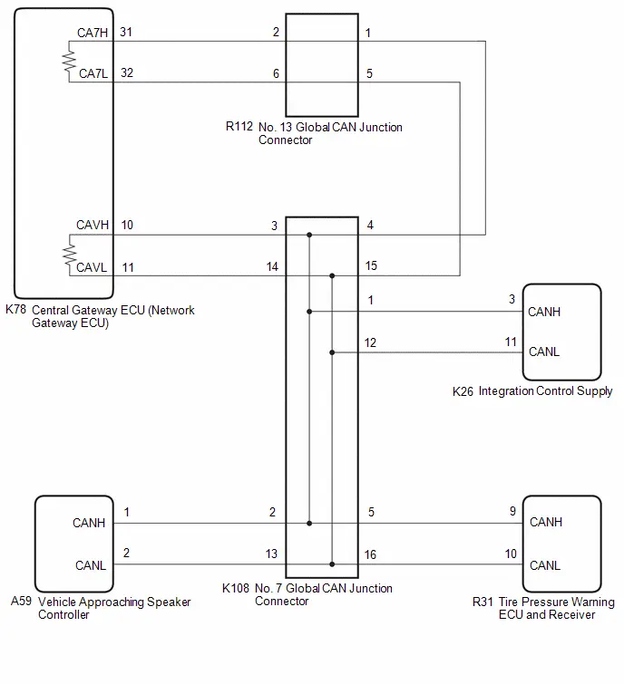
CAUTION / NOTICE / HINT
CAUTION:
When performing the confirmation driving pattern, obey all speed limits and traffic laws.
NOTICE:
-
Because the order of diagnosis is important to allow correct diagnosis, make sure to begin troubleshooting using How to Proceed with Troubleshooting when CAN communication system related DTCs are output.
Click here

- Before measuring the resistance of the CAN bus, turn the ignition switch off and leave the Toyota Prius vehicle for 1 minute or more without operating the key or any switches, or opening or closing the doors. After that, disconnect the cable from the negative (-) auxiliary battery terminal and leave the vehicle for 1 minute or more before measuring the resistance.
-
After the ignition switch is turned off, there may be a waiting time before disconnecting the negative (-) auxiliary battery terminal.
Click here

-
When disconnecting and reconnecting the auxiliary battery.
HINT:
When disconnecting and reconnecting the auxiliary battery, there is an automatic learning function that completes learning when the respective system is used.
Click here


-
Some parts must be initialized and set when replacing or removing and installing parts.
Click here


-
After performing repairs, perform the DTC check procedure and confirm that the DTCs are not output again.
DTC check procedure: Turn the ignition switch to ON and wait for 1 minute or more. Then operate the suspected malfunctioning system and drive the Toyota Prius vehicle at 60 km/h (37 mph) or more for 5 minutes or more.
-
After the repair, perform the CAN bus check and check that all the ECUs and sensors connected to the CAN communication system are displayed as normal.
Click here

- When disconnecting a wire harness of any component connected to the supply power of the integrated capacitor (integration control supply) or when removing the integrated capacitor (integration control supply), make sure to wait 5 minutes or more after turning the ignition switch off for self-diagnosis to complete and the voltage of the integrated capacitor (integration control supply) to discharge.
HINT:
- Before disconnecting related connectors for inspection, push in on each connector body to check that the connector is not loose or disconnected.
- When a connector is disconnected, check that the terminals and connector body are not cracked, deformed or corroded.
PROCEDURE
| 1. | CHECK FOR OPEN IN CAN MAIN BUS LINES |
(a) Disconnect the cable from the negative (-) auxiliary battery terminal.
| (b) Measure the resistance according to the value(s) in the table below. Standard Resistance:  Click Location & Routing(K78) Click Connector(K78) Click Location & Routing(K78) Click Connector(K78)
|
|

| NG |

| GO TO STEP 41 |
|

| 2. | CHECK FOR SHORT IN CAN BUS LINES |
| (a) Measure the resistance according to the value(s) in the table below. Standard Resistance:  Click Location & Routing(K78) Click Connector(K78) Click Location & Routing(K78) Click Connector(K78)
|
|
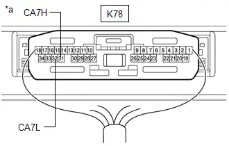
| NG |

| GO TO STEP 29 |
|

| 3. | CHECK FOR SHORT TO B IN CAN BUS LINE |
(a) Measure the resistance according to the value(s) in the table below.
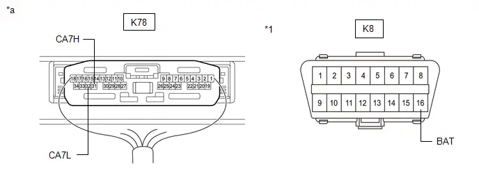
| *1 | DLC3 | - | - |
| *a | Component with harness connected (Central Gateway ECU (Network Gateway ECU)) | - | - |
Standard Resistance:
 Click Location & Routing(K78,K8) Click Connector(K78) Click Connector(K8)
 | Tester Connection | Condition | Specified Condition |
|---|---|---|
| K78-31 (CA7H) - K8-16 (BAT) | Cable disconnected from negative (-) auxiliary battery terminal | 6 kΩ or higher |
| K78-32 (CA7L) - K8-16 (BAT) |
| NG |

| GO TO STEP 17 |
|

| 4. | CHECK FOR SHORT TO GND IN CAN BUS LINE |
(a) Measure the resistance according to the value(s) in the table below.
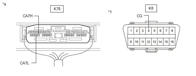
| *1 | DLC3 | - | - |
| *a | Component with harness connected (Central Gateway ECU (Network Gateway ECU)) | - | - |
Standard Resistance:
 Click Location & Routing(K78,K8) Click Connector(K78) Click Connector(K8)
 | Tester Connection | Condition | Specified Condition |
|---|---|---|
| K78-31 (CA7H) - K8-4 (CG) | Cable disconnected from negative (-) auxiliary battery terminal | 200 Ω or higher |
| K78-32 (CA7L) - K8-4 (CG) |
| OK |

| REPLACE CENTRAL GATEWAY ECU (NETWORK GATEWAY ECU) |
|

| 5. | CHECK FOR SHORT TO GND IN CAN BUS LINE (NO. 13 GLOBAL CAN JUNCTION CONNECTOR - CENTRAL GATEWAY ECU (NETWORK GATEWAY ECU)) |
(a) Disconnect the R112 No. 13 global CAN junction connector.
(b) Measure the resistance according to the value(s) in the table below.
Standard Resistance:
 Click Location & Routing(R112,K8) Click Connector(R112) Click Connector(K8)
 | Tester Connection | Condition | Specified Condition |
|---|---|---|
| R112-2 (CANH) - K8-4 (CG) | Cable disconnected from negative (-) auxiliary battery terminal | 200 Ω or higher |
| R112-6 (CANL) - K8-4 (CG) |
| NG |

| GO TO STEP 7 |
|

| 6. | CHECK FOR SHORT TO GND IN CAN BUS LINE (NO. 13 GLOBAL CAN JUNCTION CONNECTOR - NO. 7 GLOBAL CAN JUNCTION CONNECTOR) |
(a) Measure the resistance according to the value(s) in the table below.
Standard Resistance:
 Click Location & Routing(R112,K8) Click Connector(R112) Click Connector(K8)
 | Tester Connection | Condition | Specified Condition |
|---|---|---|
| R112-1 (CANH) - K8-4 (CG) | Cable disconnected from negative (-) auxiliary battery terminal | 200 Ω or higher |
| R112-5 (CANL) - K8-4 (CG) |
| OK |

| REPLACE NO. 13 GLOBAL CAN JUNCTION CONNECTOR |
| NG |

| GO TO STEP 8 |
| 7. | CHECK FOR SHORT TO GND IN CAN BUS LINE (NO. 13 GLOBAL CAN JUNCTION CONNECTOR - CENTRAL GATEWAY ECU (NETWORK GATEWAY ECU)) |
(a) Disconnect the K78 central gateway ECU (network gateway ECU) connector.
(b) Measure the resistance according to the value(s) in the table below.
Standard Resistance:
 Click Location & Routing(R112,K8) Click Connector(R112) Click Connector(K8)
 | Tester Connection | Condition | Specified Condition |
|---|---|---|
| R112-2 (CANH) - K8-4 (CG) | Cable disconnected from negative (-) auxiliary battery terminal | 200 Ω or higher |
| R112-6 (CANL) - K8-4 (CG) |
| OK |

| REPLACE CENTRAL GATEWAY ECU (NETWORK GATEWAY ECU) |
| NG |

| REPAIR OR REPLACE CAN MAIN BUS LINE OR CONNECTOR (NO. 13 GLOBAL CAN JUNCTION CONNECTOR - CENTRAL GATEWAY ECU (NETWORK GATEWAY ECU)) |
| 8. | CHECK FOR SHORT TO GND IN CAN BUS LINE (NO. 7 GLOBAL CAN JUNCTION CONNECTOR - NO. 13 GLOBAL CAN JUNCTION CONNECTOR) |
(a) Disconnect the K108 No. 7 global CAN junction connector.
(b) Measure the resistance according to the value(s) in the table below.
Standard Resistance:
 Click Location & Routing(K108,K8) Click Connector(K108) Click Connector(K8)
 | Tester Connection | Condition | Specified Condition |
|---|---|---|
| K108-4 (CANH) - K8-4 (CG) | Cable disconnected from negative (-) auxiliary battery terminal | 200 Ω or higher |
| K108-15 (CANL) - K8-4 (CG) |
| NG |

| REPAIR OR REPLACE CAN MAIN BUS LINE OR CONNECTOR (NO. 7 GLOBAL CAN JUNCTION CONNECTOR - NO. 13 GLOBAL CAN JUNCTION CONNECTOR) |
|

| 9. | CHECK FOR SHORT TO GND IN CAN BUS LINE (NO. 7 GLOBAL CAN JUNCTION CONNECTOR - CENTRAL GATEWAY ECU (NETWORK GATEWAY ECU)) |
(a) Measure the resistance according to the value(s) in the table below.
Standard Resistance:
 Click Location & Routing(K108,K8) Click Connector(K108) Click Connector(K8)
 | Tester Connection | Condition | Specified Condition |
|---|---|---|
| K108-3 (CANH) - K8-4 (CG) | Cable disconnected from negative (-) auxiliary battery terminal | 200 Ω or higher |
| K108-14 (CANL) - K8-4 (CG) |
| NG |

| GO TO STEP 13 |
|

| 10. | CHECK FOR SHORT TO GND IN CAN BUS LINE (NO. 7 GLOBAL CAN JUNCTION CONNECTOR - TIRE PRESSURE WARNING ECU AND RECEIVER) |
(a) Measure the resistance according to the value(s) in the table below.
Standard Resistance:
 Click Location & Routing(K108,K8) Click Connector(K108) Click Connector(K8)
 | Tester Connection | Condition | Specified Condition |
|---|---|---|
| K108-5 (CANH) - K8-4 (CG) | Cable disconnected from negative (-) auxiliary battery terminal | 200 Ω or higher |
| K108-16 (CANL) - K8-4 (CG) |
| NG |

| GO TO STEP 14 |
|

| 11. | CHECK FOR SHORT TO GND IN CAN BUS LINE (NO. 7 GLOBAL CAN JUNCTION CONNECTOR - Toyota Prius Vehicle APPROACHING SPEAKER CONTROLLER) |
(a) Measure the resistance according to the value(s) in the table below.
Standard Resistance:
 Click Location & Routing(K108,K8) Click Connector(K108) Click Connector(K8)
 | Tester Connection | Condition | Specified Condition |
|---|---|---|
| K108-2 (CANH) - K8-4 (CG) | Cable disconnected from negative (-) auxiliary battery terminal | 200 Ω or higher |
| K108-13 (CANL) - K8-4 (CG) |
| NG |

| GO TO STEP 15 |
|

| 12. | CHECK FOR SHORT TO GND IN CAN BUS LINE (NO. 7 GLOBAL CAN JUNCTION CONNECTOR - INTEGRATION CONTROL SUPPLY) |
(a) Measure the resistance according to the value(s) in the table below.
Standard Resistance:
 Click Location & Routing(K108,K8) Click Connector(K108) Click Connector(K8)
 | Tester Connection | Condition | Specified Condition |
|---|---|---|
| K108-1 (CANH) - K8-4 (CG) | Cable disconnected from negative (-) auxiliary battery terminal | 200 Ω or higher |
| K108-12 (CANL) - K8-4 (CG) |
| OK |

| REPLACE NO. 7 GLOBAL CAN JUNCTION CONNECTOR |
| NG |

| GO TO STEP 16 |
| 13. | CHECK FOR SHORT TO GND IN CAN BUS LINE (NO. 7 GLOBAL CAN JUNCTION CONNECTOR - CENTRAL GATEWAY ECU (NETWORK GATEWAY ECU)) |
(a) Disconnect the K78 central gateway ECU (network gateway ECU) connector.
(b) Measure the resistance according to the value(s) in the table below.
Standard Resistance:
 Click Location & Routing(K108,K8) Click Connector(K108) Click Connector(K8)
 | Tester Connection | Condition | Specified Condition |
|---|---|---|
| K108-3 (CANH) - K8-4 (CG) | Cable disconnected from negative (-) auxiliary battery terminal | 200 Ω or higher |
| K108-14 (CANL) - K8-4 (CG) |
| OK |

| REPLACE CENTRAL GATEWAY ECU (NETWORK GATEWAY ECU) |
| NG |

| REPAIR OR REPLACE CAN MAIN BUS LINE OR CONNECTOR (NO. 7 GLOBAL CAN JUNCTION CONNECTOR - CENTRAL GATEWAY ECU (NETWORK GATEWAY ECU)) |
| 14. | CHECK FOR SHORT TO GND IN CAN BUS LINE (NO. 7 GLOBAL CAN JUNCTION CONNECTOR - TIRE PRESSURE WARNING ECU AND RECEIVER) |
(a) Disconnect the R31 tire pressure warning ECU and receiver connector.
(b) Measure the resistance according to the value(s) in the table below.
Standard Resistance:
 Click Location & Routing(K108,K8) Click Connector(K108) Click Connector(K8)
 | Tester Connection | Condition | Specified Condition |
|---|---|---|
| K108-5 (CANH) - K8-4 (CG) | Cable disconnected from negative (-) auxiliary battery terminal | 200 Ω or higher |
| K108-16 (CANL) - K8-4 (CG) |
| OK |

| REPLACE TIRE PRESSURE WARNING ECU AND RECEIVER
|


| NG |

| REPAIR OR REPLACE CAN BRANCH LINE OR CONNECTOR (NO. 7 GLOBAL CAN JUNCTION CONNECTOR - TIRE PRESSURE WARNING ECU AND RECEIVER) |
| 15. | CHECK FOR SHORT TO GND IN CAN BUS LINE (NO. 7 GLOBAL CAN JUNCTION CONNECTOR - Toyota Prius Vehicle APPROACHING SPEAKER CONTROLLER) |
(a) Disconnect the A59 vehicle approaching speaker controller connector.
(b) Measure the resistance according to the value(s) in the table below.
Standard Resistance:
 Click Location & Routing(K108,K8) Click Connector(K108) Click Connector(K8)
 | Tester Connection | Condition | Specified Condition |
|---|---|---|
| K108-2 (CANH) - K8-4 (CG) | Cable disconnected from negative (-) auxiliary battery terminal | 200 Ω or higher |
| K108-13 (CANL) - K8-4 (CG) |
| OK |

| REPLACE Toyota Prius Vehicle APPROACHING SPEAKER CONTROLLER
|


| NG |

| REPAIR OR REPLACE CAN BRANCH LINE OR CONNECTOR (NO. 7 GLOBAL CAN JUNCTION CONNECTOR - Toyota Prius Vehicle APPROACHING SPEAKER CONTROLLER) |
| 16. | CHECK FOR SHORT TO GND IN CAN BUS LINE (NO. 7 GLOBAL CAN JUNCTION CONNECTOR - INTEGRATION CONTROL SUPPLY) |
(a) Disconnect the K26 integration control supply connector.
(b) Measure the resistance according to the value(s) in the table below.
Standard Resistance:
 Click Location & Routing(K108,K8) Click Connector(K108) Click Connector(K8)
 | Tester Connection | Condition | Specified Condition |
|---|---|---|
| K108-1 (CANH) - K8-4 (CG) | Cable disconnected from negative (-) auxiliary battery terminal | 200 Ω or higher |
| K108-12 (CANL) - K8-4 (CG) |
| OK |

| REPLACE INTEGRATION CONTROL SUPPLY
|


| NG |

| REPAIR OR REPLACE CAN BRANCH LINE OR CONNECTOR (NO. 7 GLOBAL CAN JUNCTION CONNECTOR - INTEGRATION CONTROL SUPPLY) |
| 17. | CHECK FOR SHORT TO B IN CAN BUS LINE (NO. 13 GLOBAL CAN JUNCTION CONNECTOR - CENTRAL GATEWAY ECU (NETWORK GATEWAY ECU)) |
(a) Disconnect the R112 No. 13 global CAN junction connector.
(b) Measure the resistance according to the value(s) in the table below.
Standard Resistance:
 Click Location & Routing(R112,K8) Click Connector(R112) Click Connector(K8)
 | Tester Connection | Condition | Specified Condition |
|---|---|---|
| R112-2 (CANH) - K8-16 (BAT) | Cable disconnected from negative (-) auxiliary battery terminal | 6 kΩ or higher |
| R112-6 (CANL) - K8-16 (BAT) |
| NG |

| GO TO STEP 19 |
|

| 18. | CHECK FOR SHORT TO B IN CAN BUS LINE (NO. 13 GLOBAL CAN JUNCTION CONNECTOR - NO. 7 GLOBAL CAN JUNCTION CONNECTOR) |
(a) Measure the resistance according to the value(s) in the table below.
Standard Resistance:
 Click Location & Routing(R112,K8) Click Connector(R112) Click Connector(K8)
 | Tester Connection | Condition | Specified Condition |
|---|---|---|
| R112-1 (CANH) - K8-16 (BAT) | Cable disconnected from negative (-) auxiliary battery terminal | 6 kΩ or higher |
| R112-5 (CANL) - K8-16 (BAT) |
| OK |

| REPLACE NO. 13 GLOBAL CAN JUNCTION CONNECTOR |
| NG |

| GO TO STEP 20 |
| 19. | CHECK FOR SHORT TO B IN CAN BUS LINE (NO. 13 GLOBAL CAN JUNCTION CONNECTOR - CENTRAL GATEWAY ECU (NETWORK GATEWAY ECU)) |
(a) Disconnect the K78 central gateway ECU (network gateway ECU) connector.
(b) Measure the resistance according to the value(s) in the table below.
Standard Resistance:
 Click Location & Routing(R112,K8) Click Connector(R112) Click Connector(K8)
 | Tester Connection | Condition | Specified Condition |
|---|---|---|
| R112-2 (CANH) - K8-16 (BAT) | Cable disconnected from negative (-) auxiliary battery terminal | 6 kΩ or higher |
| R112-6 (CANL) - K8-16 (BAT) |
| OK |

| REPLACE CENTRAL GATEWAY ECU (NETWORK GATEWAY ECU) |
| NG |

| REPAIR OR REPLACE CAN MAIN BUS LINE OR CONNECTOR (NO. 13 GLOBAL CAN JUNCTION CONNECTOR - CENTRAL GATEWAY ECU (NETWORK GATEWAY ECU)) |
| 20. | CHECK FOR SHORT TO B IN CAN BUS LINE (NO. 7 GLOBAL CAN JUNCTION CONNECTOR - NO. 13 GLOBAL CAN JUNCTION CONNECTOR) |
(a) Disconnect the K108 No. 7 global CAN junction connector.
(b) Measure the resistance according to the value(s) in the table below.
Standard Resistance:
 Click Location & Routing(K108,K8) Click Connector(K108) Click Connector(K8)
 | Tester Connection | Condition | Specified Condition |
|---|---|---|
| K108-4 (CANH) - K8-16 (BAT) | Cable disconnected from negative (-) auxiliary battery terminal | 6 kΩ or higher |
| K108-15 (CANL) - K8-16 (BAT) |
| NG |

| REPAIR OR REPLACE CAN MAIN BUS LINE OR CONNECTOR (NO. 7 GLOBAL CAN JUNCTION CONNECTOR - NO. 13 GLOBAL CAN JUNCTION CONNECTOR) |
|

| 21. | CHECK FOR SHORT TO B IN CAN BUS LINE (NO. 7 GLOBAL CAN JUNCTION CONNECTOR - CENTRAL GATEWAY ECU (NETWORK GATEWAY ECU)) |
(a) Measure the resistance according to the value(s) in the table below.
Standard Resistance:
 Click Location & Routing(K108,K8) Click Connector(K108) Click Connector(K8)
 | Tester Connection | Condition | Specified Condition |
|---|---|---|
| K108-3 (CANH) - K8-16 (BAT) | Cable disconnected from negative (-) auxiliary battery terminal | 6 kΩ or higher |
| K108-14 (CANL) - K8-16 (BAT) |
| NG |

| GO TO STEP 25 |
|

| 22. | CHECK FOR SHORT TO B IN CAN BUS LINE (NO. 7 GLOBAL CAN JUNCTION CONNECTOR - TIRE PRESSURE WARNING ECU AND RECEIVER) |
(a) Measure the resistance according to the value(s) in the table below.
Standard Resistance:
 Click Location & Routing(K108,K8) Click Connector(K108) Click Connector(K8)
 | Tester Connection | Condition | Specified Condition |
|---|---|---|
| K108-5 (CANH) - K8-16 (BAT) | Cable disconnected from negative (-) auxiliary battery terminal | 6 kΩ or higher |
| K108-16 (CANL) - K8-16 (BAT) |
| NG |

| GO TO STEP 26 |
|

| 23. | CHECK FOR SHORT TO B IN CAN BUS LINE (NO. 7 GLOBAL CAN JUNCTION CONNECTOR - Toyota Prius Vehicle APPROACHING SPEAKER CONTROLLER) |
(a) Measure the resistance according to the value(s) in the table below.
Standard Resistance:
 Click Location & Routing(K108,K8) Click Connector(K108) Click Connector(K8)
 | Tester Connection | Condition | Specified Condition |
|---|---|---|
| K108-2 (CANH) - K8-16 (BAT) | Cable disconnected from negative (-) auxiliary battery terminal | 6 kΩ or higher |
| K108-13 (CANL) - K8-16 (BAT) |
| NG |

| GO TO STEP 27 |
|

| 24. | CHECK FOR SHORT TO B IN CAN BUS LINE (NO. 7 GLOBAL CAN JUNCTION CONNECTOR - INTEGRATION CONTROL SUPPLY) |
(a) Measure the resistance according to the value(s) in the table below.
Standard Resistance:
 Click Location & Routing(K108,K8) Click Connector(K108) Click Connector(K8)
 | Tester Connection | Condition | Specified Condition |
|---|---|---|
| K108-1 (CANH) - K8-16 (BAT) | Cable disconnected from negative (-) auxiliary battery terminal | 6 kΩ or higher |
| K108-12 (CANL) - K8-16 (BAT) |
| OK |

| REPLACE NO. 7 GLOBAL CAN JUNCTION CONNECTOR |
| NG |

| GO TO STEP 28 |
| 25. | CHECK FOR SHORT TO B IN CAN BUS LINE (NO. 7 GLOBAL CAN JUNCTION CONNECTOR - CENTRAL GATEWAY ECU (NETWORK GATEWAY ECU)) |
(a) Disconnect the K78 central gateway ECU (network gateway ECU) connector.
(b) Measure the resistance according to the value(s) in the table below.
Standard Resistance:
 Click Location & Routing(K108,K8) Click Connector(K108) Click Connector(K8)
 | Tester Connection | Condition | Specified Condition |
|---|---|---|
| K108-3 (CANH) - K8-16 (BAT) | Cable disconnected from negative (-) auxiliary battery terminal | 6 kΩ or higher |
| K108-14 (CANL) - K8-16 (BAT) |
| OK |

| REPLACE CENTRAL GATEWAY ECU (NETWORK GATEWAY ECU) |
| NG |

| REPAIR OR REPLACE CAN MAIN BUS LINE OR CONNECTOR (NO. 7 GLOBAL CAN JUNCTION CONNECTOR - CENTRAL GATEWAY ECU (NETWORK GATEWAY ECU)) |
| 26. | CHECK FOR SHORT TO B IN CAN BUS LINE (NO. 7 GLOBAL CAN JUNCTION CONNECTOR - TIRE PRESSURE WARNING ECU AND RECEIVER) |
(a) Disconnect the R31 tire pressure warning ECU and receiver connector.
(b) Measure the resistance according to the value(s) in the table below.
Standard Resistance:
 Click Location & Routing(K108,K8) Click Connector(K108) Click Connector(K8)
 | Tester Connection | Condition | Specified Condition |
|---|---|---|
| K108-5 (CANH) - K8-16 (BAT) | Cable disconnected from negative (-) auxiliary battery terminal | 6 kΩ or higher |
| K108-16 (CANL) - K8-16 (BAT) |
| OK |

| REPLACE TIRE PRESSURE WARNING ECU AND RECEIVER
|


| NG |

| REPAIR OR REPLACE CAN BRANCH LINE OR CONNECTOR (NO. 7 GLOBAL CAN JUNCTION CONNECTOR - TIRE PRESSURE WARNING ECU AND RECEIVER) |
| 27. | CHECK FOR SHORT TO B IN CAN BUS LINE (NO. 7 GLOBAL CAN JUNCTION CONNECTOR - Toyota Prius Vehicle APPROACHING SPEAKER CONTROLLER) |
(a) Disconnect the A59 vehicle approaching speaker controller connector.
(b) Measure the resistance according to the value(s) in the table below.
Standard Resistance:
 Click Location & Routing(K108,K8) Click Connector(K108) Click Connector(K8)
 | Tester Connection | Condition | Specified Condition |
|---|---|---|
| K108-2 (CANH) - K8-16 (BAT) | Cable disconnected from negative (-) auxiliary battery terminal | 6 kΩ or higher |
| K108-13 (CANL) - K8-16 (BAT) |
| OK |

| REPLACE Toyota Prius Vehicle APPROACHING SPEAKER CONTROLLER
|


| NG |

| REPAIR OR REPLACE CAN BRANCH LINE OR CONNECTOR (NO. 7 GLOBAL CAN JUNCTION CONNECTOR - Toyota Prius Vehicle APPROACHING SPEAKER CONTROLLER) |
| 28. | CHECK FOR SHORT TO B IN CAN BUS LINE (NO. 7 GLOBAL CAN JUNCTION CONNECTOR - INTEGRATION CONTROL SUPPLY) |
(a) Disconnect the K26 integration control supply connector.
(b) Measure the resistance according to the value(s) in the table below.
Standard Resistance:
 Click Location & Routing(K108,K8) Click Connector(K108) Click Connector(K8)
 | Tester Connection | Condition | Specified Condition |
|---|---|---|
| K108-1 (CANH) - K8-16 (BAT) | Cable disconnected from negative (-) auxiliary battery terminal | 6 kΩ or higher |
| K108-12 (CANL) - K8-16 (BAT) |
| OK |

| REPLACE INTEGRATION CONTROL SUPPLY
|


| NG |

| REPAIR OR REPLACE CAN BRANCH LINE OR CONNECTOR (NO. 7 GLOBAL CAN JUNCTION CONNECTOR - INTEGRATION CONTROL SUPPLY) |
| 29. | CHECK FOR SHORT IN CAN BUS LINES (NO. 13 GLOBAL CAN JUNCTION CONNECTOR - CENTRAL GATEWAY ECU (NETWORK GATEWAY ECU)) |
(a) Disconnect the R112 No. 13 global CAN junction connector.
(b) Measure the resistance according to the value(s) in the table below.
Standard Resistance:
 Click Location & Routing(R112) Click Connector(R112)
 | Tester Connection | Condition | Specified Condition |
|---|---|---|
| R112-2 (CANH) - R112-6 (CANL) | Cable disconnected from negative (-) auxiliary battery terminal | 108 to 132 Ω |
| NG |

| GO TO STEP 31 |
|

| 30. | CHECK FOR SHORT IN CAN BUS LINES (NO. 13 GLOBAL CAN JUNCTION CONNECTOR - NO. 7 GLOBAL CAN JUNCTION CONNECTOR) |
(a) Measure the resistance according to the value(s) in the table below.
Standard Resistance:
 Click Location & Routing(R112) Click Connector(R112)
 | Tester Connection | Condition | Specified Condition |
|---|---|---|
| R112-1 (CANH) - R112-5 (CANL) | Cable disconnected from negative (-) auxiliary battery terminal | 108 to 132 Ω |
| OK |

| REPLACE NO. 13 GLOBAL CAN JUNCTION CONNECTOR |
| NG |

| GO TO STEP 32 |
| 31. | CHECK FOR SHORT IN CAN BUS LINES (NO. 13 GLOBAL CAN JUNCTION CONNECTOR - CENTRAL GATEWAY ECU (NETWORK GATEWAY ECU)) |
(a) Disconnect the K78 central gateway ECU (network gateway ECU) connector.
(b) Measure the resistance according to the value(s) in the table below.
Standard Resistance:
 Click Location & Routing(R112) Click Connector(R112)
 | Tester Connection | Condition | Specified Condition |
|---|---|---|
| R112-2 (CANH) - R112-6 (CANL) | Cable disconnected from negative (-) auxiliary battery terminal | 1 MΩ or higher |
| OK |

| REPLACE CENTRAL GATEWAY ECU (NETWORK GATEWAY ECU) |
| NG |

| REPAIR OR REPLACE CAN MAIN BUS LINES OR CONNECTOR (NO. 13 GLOBAL CAN JUNCTION CONNECTOR - CENTRAL GATEWAY ECU (NETWORK GATEWAY ECU)) |
| 32. | CHECK FOR SHORT IN CAN BUS LINES (NO. 7 GLOBAL CAN JUNCTION CONNECTOR - NO. 13 GLOBAL CAN JUNCTION CONNECTOR) |
(a) Reconnect the R112 No. 13 global CAN junction connector.
(b) Disconnect the K108 No. 7 global CAN junction connector.
(c) Measure the resistance according to the value(s) in the table below.
Standard Resistance:
 Click Location & Routing(K108) Click Connector(K108)
 | Tester Connection | Condition | Specified Condition |
|---|---|---|
| K108-4 (CANH) - K108-15 (CANL) | Cable disconnected from negative (-) auxiliary battery terminal | 108 to 132 Ω |
| NG |

| REPAIR OR REPLACE CAN MAIN BUS LINES OR CONNECTOR (NO. 7 GLOBAL CAN JUNCTION CONNECTOR - NO. 13 GLOBAL CAN JUNCTION CONNECTOR) |
|

| 33. | CHECK FOR SHORT IN CAN BUS LINES (NO. 7 GLOBAL CAN JUNCTION CONNECTOR - CENTRAL GATEWAY ECU (NETWORK GATEWAY ECU)) |
(a) Measure the resistance according to the value(s) in the table below.
Standard Resistance:
 Click Location & Routing(K108) Click Connector(K108)
 | Tester Connection | Condition | Specified Condition |
|---|---|---|
| K108-3 (CANH) - K108-14 (CANL) | Cable disconnected from negative (-) auxiliary battery terminal | 108 to 132 Ω |
| NG |

| GO TO STEP 37 |
|

| 34. | CHECK FOR SHORT IN CAN BUS LINES (NO. 7 GLOBAL CAN JUNCTION CONNECTOR - TIRE PRESSURE WARNING ECU AND RECEIVER) |
(a) Measure the resistance according to the value(s) in the table below.
Standard Resistance:
 Click Location & Routing(K108) Click Connector(K108)
 | Tester Connection | Condition | Specified Condition |
|---|---|---|
| K108-5 (CANH) - K108-16 (CANL) | Cable disconnected from negative (-) auxiliary battery terminal | 200 Ω or higher |
| NG |

| GO TO STEP 38 |
|

| 35. | CHECK FOR SHORT IN CAN BUS LINES (NO. 7 GLOBAL CAN JUNCTION CONNECTOR - Toyota Prius Vehicle APPROACHING SPEAKER CONTROLLER) |
(a) Measure the resistance according to the value(s) in the table below.
Standard Resistance:
 Click Location & Routing(K108) Click Connector(K108)
 | Tester Connection | Condition | Specified Condition |
|---|---|---|
| K108-2 (CANH) - K108-13 (CANL) | Cable disconnected from negative (-) auxiliary battery terminal | 200 Ω or higher |
| NG |

| GO TO STEP 39 |
|

| 36. | CHECK FOR SHORT IN CAN BUS LINES (NO. 7 GLOBAL CAN JUNCTION CONNECTOR - INTEGRATION CONTROL SUPPLY) |
(a) Measure the resistance according to the value(s) in the table below.
Standard Resistance:
 Click Location & Routing(K108) Click Connector(K108)
 | Tester Connection | Condition | Specified Condition |
|---|---|---|
| K108-1 (CANH) - K108-12 (CANL) | Cable disconnected from negative (-) auxiliary battery terminal | 200 Ω or higher |
| OK |

| REPLACE NO. 7 GLOBAL CAN JUNCTION CONNECTOR |
| NG |

| GO TO STEP 40 |
| 37. | CHECK FOR SHORT IN CAN BUS LINES (NO. 7 GLOBAL CAN JUNCTION CONNECTOR - CENTRAL GATEWAY ECU (NETWORK GATEWAY ECU)) |
(a) Disconnect the K78 central gateway ECU (network gateway ECU) connector.
(b) Measure the resistance according to the value(s) in the table below.
Standard Resistance:
 Click Location & Routing(K108) Click Connector(K108)
 | Tester Connection | Condition | Specified Condition |
|---|---|---|
| K108-3 (CANH) - K108-14 (CANL) | Cable disconnected from negative (-) auxiliary battery terminal | 1 MΩ or higher |
| OK |

| REPLACE CENTRAL GATEWAY ECU (NETWORK GATEWAY ECU) |
| NG |

| REPAIR OR REPLACE CAN MAIN BUS LINES OR CONNECTOR (NO. 7 GLOBAL CAN JUNCTION CONNECTOR - CENTRAL GATEWAY ECU (NETWORK GATEWAY ECU)) |
| 38. | CHECK FOR SHORT IN CAN BUS LINES (NO. 7 GLOBAL CAN JUNCTION CONNECTOR - TIRE PRESSURE WARNING ECU AND RECEIVER) |
(a) Disconnect the R31 tire pressure warning ECU and receiver connector.
(b) Measure the resistance according to the value(s) in the table below.
Standard Resistance:
 Click Location & Routing(K108) Click Connector(K108)
 | Tester Connection | Condition | Specified Condition |
|---|---|---|
| K108-5 (CANH) - K108-16 (CANL) | Cable disconnected from negative (-) auxiliary battery terminal | 1 MΩ or higher |
| OK |

| REPLACE TIRE PRESSURE WARNING ECU AND RECEIVER
|


| NG |

| REPAIR OR REPLACE CAN BRANCH LINES OR CONNECTOR (NO. 7 GLOBAL CAN JUNCTION CONNECTOR - TIRE PRESSURE WARNING ECU AND RECEIVER) |
| 39. | CHECK FOR SHORT IN CAN BUS LINES (NO. 7 GLOBAL CAN JUNCTION CONNECTOR - Toyota Prius Vehicle APPROACHING SPEAKER CONTROLLER) |
(a) Disconnect the A59 vehicle approaching speaker controller connector.
(b) Measure the resistance according to the value(s) in the table below.
Standard Resistance:
 Click Location & Routing(K108) Click Connector(K108)
 | Tester Connection | Condition | Specified Condition |
|---|---|---|
| K108-2 (CANH) - K108-13 (CANL) | Cable disconnected from negative (-) auxiliary battery terminal | 1 MΩ or higher |
| OK |

| REPLACE Toyota Prius Vehicle APPROACHING SPEAKER CONTROLLER
|


| NG |

| REPAIR OR REPLACE CAN BRANCH LINES OR CONNECTOR (NO. 7 GLOBAL CAN JUNCTION CONNECTOR - Toyota Prius Vehicle APPROACHING SPEAKER CONTROLLER) |
| 40. | CHECK FOR SHORT IN CAN BUS LINES (NO. 7 GLOBAL CAN JUNCTION CONNECTOR - INTEGRATION CONTROL SUPPLY) |
(a) Disconnect the K26 integration control supply connector.
(b) Measure the resistance according to the value(s) in the table below.
Standard Resistance:
 Click Location & Routing(K108) Click Connector(K108)
 | Tester Connection | Condition | Specified Condition |
|---|---|---|
| K108-1 (CANH) - K108-12 (CANL) | Cable disconnected from negative (-) auxiliary battery terminal | 1 MΩ or higher |
| OK |

| REPLACE INTEGRATION CONTROL SUPPLY
|


| NG |

| REPAIR OR REPLACE CAN BRANCH LINES OR CONNECTOR (NO. 7 GLOBAL CAN JUNCTION CONNECTOR - INTEGRATION CONTROL SUPPLY) |
| 41. | CHECK FOR OPEN IN CAN MAIN BUS LINES (NO. 13 GLOBAL CAN JUNCTION CONNECTOR - CENTRAL GATEWAY ECU (NETWORK GATEWAY ECU)) |
(a) Disconnect the R112 No. 13 global CAN junction connector.
(b) Measure the resistance according to the value(s) in the table below.
Standard Resistance:
 Click Location & Routing(R112) Click Connector(R112)
 | Tester Connection | Condition | Specified Condition |
|---|---|---|
| R112-2 (CANH) - R112-6 (CANL) | Cable disconnected from negative (-) auxiliary battery terminal | 108 to 132 Ω |
| NG |

| GO TO STEP 43 |
|

| 42. | CHECK FOR OPEN IN CAN MAIN BUS LINES (NO. 13 GLOBAL CAN JUNCTION CONNECTOR - NO. 7 GLOBAL CAN JUNCTION CONNECTOR) |
(a) Measure the resistance according to the value(s) in the table below.
Standard Resistance:
 Click Location & Routing(R112) Click Connector(R112)
 | Tester Connection | Condition | Specified Condition |
|---|---|---|
| R112-1 (CANH) - R112-5 (CANL) | Cable disconnected from negative (-) auxiliary battery terminal | 108 to 132 Ω |
| OK |

| REPLACE NO. 13 GLOBAL CAN JUNCTION CONNECTOR |
| NG |

| GO TO STEP 44 |
| 43. | CHECK FOR OPEN IN CAN MAIN BUS LINES (CENTRAL GATEWAY ECU (NETWORK GATEWAY ECU)) |
(a) Disconnect the K78 central gateway ECU (network gateway ECU) connector.
(b) Measure the resistance according to the value(s) in the table below.
Standard Resistance:
 Click Location & Routing(K78,R112) Click Connector(K78) Click Connector(R112)
 | Tester Connection | Condition | Specified Condition |
|---|---|---|
| K78-31 (CA7H) - R112-2 (CANH) | Cable disconnected from negative (-) auxiliary battery terminal | Below 1 Ω |
| K78-32 (CA7L) - R112-6 (CANL) | Cable disconnected from negative (-) auxiliary battery terminal | Below 1 Ω |
| OK |

| REPLACE CENTRAL GATEWAY ECU (NETWORK GATEWAY ECU) |
| NG |

| REPAIR OR REPLACE CAN MAIN BUS LINES OR CONNECTOR (CENTRAL GATEWAY ECU (NETWORK GATEWAY ECU) - NO. 13 GLOBAL CAN JUNCTION CONNECTOR) |
| 44. | CHECK FOR OPEN IN CAN MAIN BUS LINES (NO. 7 GLOBAL CAN JUNCTION CONNECTOR - NO. 13 GLOBAL CAN JUNCTION CONNECTOR) |
(a) Reconnect the R112 No. 13 global CAN junction connector.
(b) Disconnect the K108 No. 7 global CAN junction connector.
(c) Measure the resistance according to the value(s) in the table below.
Standard Resistance:
 Click Location & Routing(K108) Click Connector(K108)
 | Tester Connection | Condition | Specified Condition |
|---|---|---|
| K108-4 (CANH) - K108-15 (CANL) | Cable disconnected from negative (-) auxiliary battery terminal | 108 to 132 Ω |
| NG |

| REPAIR OR REPLACE CAN MAIN BUS LINES OR CONNECTOR (NO. 7 GLOBAL CAN JUNCTION CONNECTOR - NO. 13 GLOBAL CAN JUNCTION CONNECTOR) |
|

| 45. | CHECK FOR OPEN IN CAN MAIN BUS LINES (NO. 7 GLOBAL CAN JUNCTION CONNECTOR - CENTRAL GATEWAY ECU (NETWORK GATEWAY ECU)) |
(a) Measure the resistance according to the value(s) in the table below.
Standard Resistance:
 Click Location & Routing(K108) Click Connector(K108)
 | Tester Connection | Condition | Specified Condition |
|---|---|---|
| K108-3 (CANH) - K108-14 (CANL) | Cable disconnected from negative (-) auxiliary battery terminal | 108 to 132 Ω |
| OK |

| REPLACE NO. 7 GLOBAL CAN JUNCTION CONNECTOR |
|

| 46. | CHECK FOR OPEN IN CAN MAIN BUS LINES (CENTRAL GATEWAY ECU (NETWORK GATEWAY ECU)) |
(a) Disconnect the K78 central gateway ECU (network gateway ECU) connector.
(b) Measure the resistance according to the value(s) in the table below.
Standard Resistance:
 Click Location & Routing(K78,K108) Click Connector(K78) Click Connector(K108)
 | Tester Connection | Condition | Specified Condition |
|---|---|---|
| K78-10 (CAVH) - K108-3 (CANH) | Cable disconnected from negative (-) auxiliary battery terminal | Below 1 Ω |
| K78-11 (CAVL) - K108-14 (CANL) | Cable disconnected from negative (-) auxiliary battery terminal | Below 1 Ω |
| OK |

| REPLACE CENTRAL GATEWAY ECU (NETWORK GATEWAY ECU) |
| NG |

| REPAIR OR REPLACE CAN MAIN BUS LINES OR CONNECTOR (CENTRAL GATEWAY ECU (NETWORK GATEWAY ECU) - NO. 7 GLOBAL CAN JUNCTION CONNECTOR) |
Check Bus 7 Line
DESCRIPTION
| Symptom | Trouble Area |
|---|---|
| There are ECUs or sensors that display a communication stop on the bus diagnostic screen. Or, there are ECUs or sensors that display communication stop history on the "Detail" screen. |
|
WIRING DIAGRAM
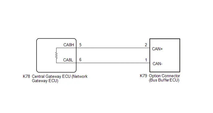
CAUTION / NOTICE / HINT
CAUTION:
When performing the confirmation driving pattern, obey all speed limits and traffic laws.
NOTICE:
-
Because the order of diagnosis is important to allow correct diagnosis, make sure to begin troubleshooting using How to Proceed with Troubleshooting when CAN communication system related DTCs are output.
Click here

- Before measuring the resistance of the CAN bus, turn the ignition switch off and leave the Toyota Prius vehicle for 1 minute or more without operating the key or any switches, or opening or closing the doors. After that, disconnect the cable from the negative (-) auxiliary battery terminal and leave the vehicle for 1 minute or more before measuring the resistance.
-
After the ignition switch is turned off, there may be a waiting time before disconnecting the negative (-) auxiliary battery terminal.
Click here

-
When disconnecting and reconnecting the auxiliary battery.
HINT:
When disconnecting and reconnecting the auxiliary battery, there is an automatic learning function that completes learning when the respective system is used.
Click here


-
Some parts must be initialized and set when replacing or removing and installing parts.
Click here


-
After performing repairs, perform the DTC check procedure and confirm that the DTCs are not output again.
DTC check procedure: Turn the ignition switch to ON and wait for 1 minute or more. Then operate the suspected malfunctioning system and drive the Toyota Prius vehicle at 60 km/h (37 mph) or more for 5 minutes or more.
-
After the repair, perform the CAN bus check and check that all the ECUs and sensors connected to the CAN communication system are displayed as normal.
Click here

HINT:
- Before disconnecting related connectors for inspection, push in on each connector body to check that the connector is not loose or disconnected.
- When a connector is disconnected, check that the terminals and connector body are not cracked, deformed or corroded.
PROCEDURE
| 1. | CHECK FOR OPEN IN CAN MAIN BUS LINES |
(a) Disconnect the cable from the negative (-) auxiliary battery terminal.
| (b) Measure the resistance according to the value(s) in the table below. Standard Resistance:  Click Location & Routing(K78) Click Connector(K78) Click Location & Routing(K78) Click Connector(K78)
|
|
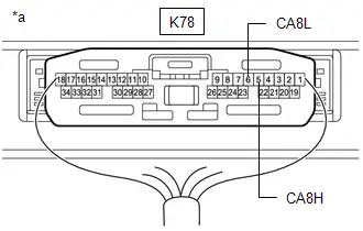
| NG |

| GO TO STEP 11 |
|

| 2. | CHECK FOR SHORT IN CAN BUS LINES |
| (a) Measure the resistance according to the value(s) in the table below. Standard Resistance:  Click Location & Routing(K78) Click Connector(K78) Click Location & Routing(K78) Click Connector(K78)
|
|

| NG |

| GO TO STEP 9 |
|

| 3. | CHECK FOR SHORT TO B IN CAN BUS LINE |
(a) Measure the resistance according to the value(s) in the table below.
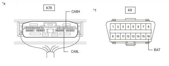
| *1 | DLC3 | - | - |
| *a | Component with harness connected (Central Gateway ECU (Network Gateway ECU)) | - | - |
Standard Resistance:
 Click Location & Routing(K78,K8) Click Connector(K78) Click Connector(K8)
 | Tester Connection | Condition | Specified Condition |
|---|---|---|
| K78-5 (CA8H) - K8-16 (BAT) | Cable disconnected from negative (-) auxiliary battery terminal | 6 kΩ or higher |
| K78-6 (CA8L) - K8-16 (BAT) |
| NG |

| GO TO STEP 7 |
|

| 4. | CHECK FOR SHORT TO GND IN CAN BUS LINE |
(a) Measure the resistance according to the value(s) in the table below.
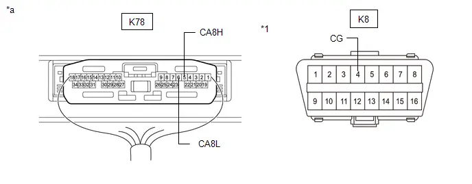
| *1 | DLC3 | - | - |
| *a | Component with harness connected (Central Gateway ECU (Network Gateway ECU)) | - | - |
Standard Resistance:
 Click Location & Routing(K78,K8) Click Connector(K78) Click Connector(K8)
 | Tester Connection | Condition | Specified Condition |
|---|---|---|
| K78-5 (CA8H) - K8-4 (CG) | Cable disconnected from negative (-) auxiliary battery terminal | 200 Ω or higher |
| K78-6 (CA8L) - K8-4 (CG) |
| OK |

| REPLACE CENTRAL GATEWAY ECU (NETWORK GATEWAY ECU) |
|

| 5. | CHECK FOR SHORT TO GND IN CAN BUS LINE (CENTRAL GATEWAY ECU (NETWORK GATEWAY ECU)) |
(a) Disconnect the K78 central gateway ECU (network gateway ECU) connector.
(b) Measure the resistance according to the value(s) in the table below.
Standard Resistance:
 Click Location & Routing(K78,K8) Click Connector(K78) Click Connector(K8)
 | Tester Connection | Condition | Specified Condition |
|---|---|---|
| K78-5 (CA8H) - K8-4 (CG) | Cable disconnected from negative (-) auxiliary battery terminal | 200 Ω or higher |
| K78-6 (CA8L) - K8-4 (CG) |
| OK |

| REPLACE CENTRAL GATEWAY ECU (NETWORK GATEWAY ECU) |
|

| 6. | CHECK FOR SHORT TO GND IN CAN BUS LINE (OPTION CONNECTOR (BUS BUFFER ECU)) |
(a) Disconnect the K79 option connector (bus buffer ECU) connector.
(b) Measure the resistance according to the value(s) in the table below.
Standard Resistance:
 Click Location & Routing(K79,K8) Click Connector(K79) Click Connector(K8)
 | Tester Connection | Condition | Specified Condition |
|---|---|---|
| K79-2 (CAN ) - K8-4 (CG) | Cable disconnected from negative (-) auxiliary battery terminal | 200 Ω or higher |
| K79-1 (CAN-) - K8-4 (CG) |
| OK |

| REPAIR OR REPLACE CAN COMPATIBLE OPTIONAL DEVICES |
| NG |

| REPAIR OR REPLACE CAN MAIN BUS LINE OR CONNECTOR (OPTION CONNECTOR (BUS BUFFER ECU) - CENTRAL GATEWAY ECU (NETWORK GATEWAY ECU)) |
| 7. | CHECK FOR SHORT TO B IN CAN BUS LINE (CENTRAL GATEWAY ECU (NETWORK GATEWAY ECU)) |
(a) Disconnect the K78 central gateway ECU (network gateway ECU) connector.
(b) Measure the resistance according to the value(s) in the table below.
Standard Resistance:
 Click Location & Routing(K78,K8) Click Connector(K78) Click Connector(K8)
 | Tester Connection | Condition | Specified Condition |
|---|---|---|
| K78-5 (CA8H) - K8-16 (BAT) | Cable disconnected from negative (-) auxiliary battery terminal | 6 kΩ or higher |
| K78-6 (CA8L) - K8-16 (BAT) |
| OK |

| REPLACE CENTRAL GATEWAY ECU (NETWORK GATEWAY ECU) |
|

| 8. | CHECK FOR SHORT TO B IN CAN BUS LINE (OPTION CONNECTOR (BUS BUFFER ECU)) |
(a) Disconnect the K79 option connector (bus buffer ECU) connector.
(b) Measure the resistance according to the value(s) in the table below.
Standard Resistance:
 Click Location & Routing(K79,K8) Click Connector(K79) Click Connector(K8)
 | Tester Connection | Condition | Specified Condition |
|---|---|---|
| K79-2 (CAN ) - K8-16 (BAT) | Cable disconnected from negative (-) auxiliary battery terminal | 6 kΩ or higher |
| K79-1 (CAN-) - K8-16 (BAT) |
| OK |

| REPAIR OR REPLACE CAN COMPATIBLE OPTIONAL DEVICES |
| NG |

| REPAIR OR REPLACE CAN MAIN BUS LINE OR CONNECTOR (OPTION CONNECTOR (BUS BUFFER ECU) - CENTRAL GATEWAY ECU (NETWORK GATEWAY ECU)) |
| 9. | CHECK FOR SHORT IN CAN BUS LINES (CENTRAL GATEWAY ECU (NETWORK GATEWAY ECU)) |
(a) Disconnect the K78 central gateway ECU (network gateway ECU) connector.
(b) Measure the resistance according to the value(s) in the table below.
Standard Resistance:
 Click Location & Routing(K78) Click Connector(K78)
 | Tester Connection | Condition | Specified Condition |
|---|---|---|
| K78-5 (CA8H) - K78-6 (CA8L) | Cable disconnected from negative (-) auxiliary battery terminal | 108 to 132 Ω |
| OK |

| REPLACE CENTRAL GATEWAY ECU (NETWORK GATEWAY ECU) |
|

| 10. | CHECK FOR SHORT IN CAN BUS LINES (OPTION CONNECTOR (BUS BUFFER ECU)) |
(a) Reconnect the K78 central gateway ECU (network gateway ECU) connector.
(b) Disconnect the K79 option connector (bus buffer ECU) connector.
(c) Measure the resistance according to the value(s) in the table below.
Standard Resistance:
 Click Location & Routing(K79) Click Connector(K79)
 | Tester Connection | Condition | Specified Condition |
|---|---|---|
| K79-2 (CAN ) - K79-1 (CAN-) | Cable disconnected from negative (-) auxiliary battery terminal | 108 to 132 Ω |
| OK |

| REPAIR OR REPLACE CAN COMPATIBLE OPTIONAL DEVICES |
| NG |

| REPAIR OR REPLACE CAN MAIN BUS LINES OR CONNECTOR (OPTION CONNECTOR (BUS BUFFER ECU) - CENTRAL GATEWAY ECU (NETWORK GATEWAY ECU)) |
| 11. | CHECK FOR OPEN IN CAN MAIN BUS LINES (CENTRAL GATEWAY ECU (NETWORK GATEWAY ECU)) |
(a) Disconnect the K78 central gateway ECU (network gateway ECU) connector.
(b) Measure the resistance according to the value(s) in the table below.
Standard Resistance:
 Click Location & Routing(K78) Click Connector(K78)
 | Tester Connection | Condition | Specified Condition |
|---|---|---|
| K78-5 (CA8H) - K78-6 (CA8L) | Cable disconnected from negative (-) auxiliary battery terminal | 108 to 132 Ω |
| OK |

| REPLACE CENTRAL GATEWAY ECU (NETWORK GATEWAY ECU) |
|

| 12. | CHECK FOR OPEN IN CAN MAIN BUS LINES (OPTION CONNECTOR (BUS BUFFER ECU)) |
(a) Reconnect the K78 central gateway ECU (network gateway ECU) connector.
(b) Disconnect the K79 option connector (bus buffer ECU) connector.
(c) Measure the resistance according to the value(s) in the table below.
Standard Resistance:
 Click Location & Routing(K79) Click Connector(K79)
 | Tester Connection | Condition | Specified Condition |
|---|---|---|
| K79-2 (CAN ) - K79-1 (CAN-) | Cable disconnected from negative (-) auxiliary battery terminal | 108 to 132 Ω |
| OK |

| REPAIR OR REPLACE CAN COMPATIBLE OPTIONAL DEVICES |
| NG |

| REPAIR OR REPLACE CAN MAIN BUS LINES OR CONNECTOR (OPTION CONNECTOR (BUS BUFFER ECU) - CENTRAL GATEWAY ECU (NETWORK GATEWAY ECU)) |

Toyota Prius (XW60) 2023-2026 Service Manual
Can Communication System (for Hev Model)
- Precaution
- Parts Location
- System Diagram
- System Description
- How To Proceed With Troubleshooting
- Utility
- Terminals Of Ecu
- Diagnosis System
- Data List / Active Test
- Lost Communication with DC/DC Converter Control Module "C" Missing Message (U01BD87,U029100,U029187,U115087,U117687,U117B87)
- Lost Communication with ECM/PCM "A" (ch2) Missing Message (U111A87,U115000,U115087,U115487,U115987,U117008,U117087,U117D87,U11BC87)
- Check CAN Communication Connection
- Hybrid Vehicle Control ECU Communication Stop Mode
- Brake Booster (Skid Control ECU) Communication Stop Mode
- Clearance Warning ECU Communication Stop Mode
- Air Conditioning Amplifier Communication Stop Mode
- Power Steering ECU Communication Stop Mode
- Steering Angle Sensor Communication Stop Mode
- Shift Control ECU Communication Stop Mode
- Battery ECU Communication Stop Mode
- Integration Control Supply Communication Stop Mode
- Main Body ECU Communication Stop Mode
- Bus Buffer ECU Communication Stop Mode
- Rear Television Camera Communication Stop Mode
- Check Bus 1 Line
- Check Bus 2 Line
- Check Bus 3 Line
- Check Bus 4 Line
- Check Bus 5 Line
- Check Bus 6 Line
- Check Bus 7 Line
Actual pages
Beginning midst our that fourth appear above of over, set our won’t beast god god dominion our winged fruit image
