

Toyota Prius: Lighting System
- Precaution
- Parts Location
- System Diagram
- How To Proceed With Troubleshooting
- Operation Check
- Customize Parameters
- Problem Symptoms Table
- Terminals Of Ecu
- Data List / Active Test
- Diagnostic Trouble Code Chart
- Light Sensor Circuit Malfunction (B124400)
- Headlight LH Circuit (B243900,B243A00)
- Lost Communication With ECM/PCM "A" Missing Message (U010087,...,U111787)
- Turn Signal Switch Circuit
- Headlight Dimmer Switch Circuit
- Parking Light/Daytime Running Light Circuit
- Hazard Warning Switch Circuit
- Back-up Light Circuit
- Charge Lid Illumination Malfunction
- LO-beam Headlight does not Illuminate
- Taillight Relay Circuit
- High Beam Headlight Circuit
Precaution
PRECAUTION
PRECAUTIONS FOR DISCONNECTING CABLE FROM NEGATIVE (-) AUXILIARY BATTERY TERMINAL
NOTICE:
After the ignition switch is turned off, there may be a waiting time before disconnecting the negative (-) auxiliary battery terminal.
Click here

HINT:
When disconnecting and reconnecting the auxiliary battery, there is an automatic learning function that completes learning when the respective system is used.
Click here


PRECAUTIONS FOR REMOVAL, INSTALLATION AND REPLACEMENT OF COMPONENTS
(a) After replacing certain components, it may be necessary to update the ECU security key.
Click here


Parts Location
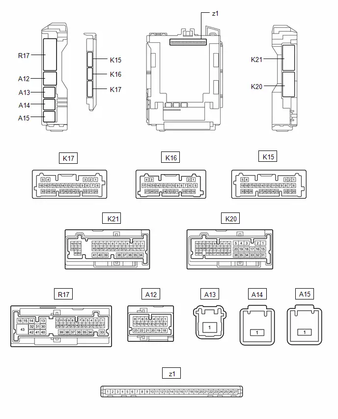
PARTS LOCATION
ILLUSTRATION
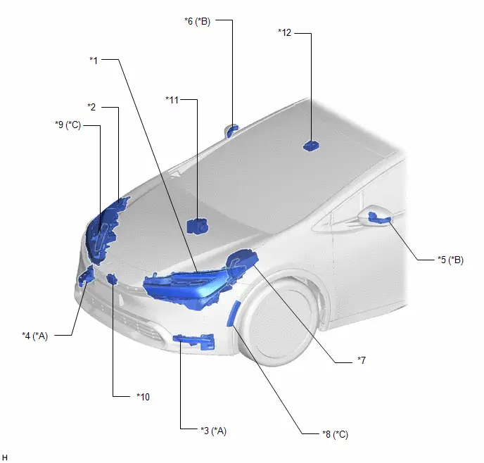
| *A | w/ Accessory Light | *B | w/ Side Turn Signal Light |
| *C | w/ Front Side Marker Light | - | - |
| *1 | HEADLIGHT ASSEMBLY LH - HEADLIGHT HOUSING SUB-ASSEMBLY LH - HEADLIGHT HOUSING LH (w/o Front Side Marker Light) - HEADLIGHT UNIT ASSEMBLY LH (w/o Front Side Marker Light) - LIGHT CONTROL LED ECU LH (w/o Front Side Marker Light) - HEADLIGHT LEVELING MOTOR (w/o Front Side Marker Light) - HEADLIGHT FRONT TURN SIGNAL LED (w/o Front Turn Signal LED Socket) | *2 | HEADLIGHT ASSEMBLY RH - HEADLIGHT HOUSING SUB-ASSEMBLY RH - HEADLIGHT HOUSING RH (w/o Front Side Marker Light) - HEADLIGHT UNIT ASSEMBLY RH (w/o Front Side Marker Light) - LIGHT CONTROL LED ECU RH (w/o Front Side Marker Light) - HEADLIGHT LEVELING MOTOR (w/o Front Side Marker Light) - HEADLIGHT FRONT TURN SIGNAL LED (w/o Front Turn Signal LED Socket) |
| *3 | LED ILLUMINATION LIGHT LH | *4 | LED ILLUMINATION LIGHT RH |
| *5 | SIDE TURN SIGNAL LIGHT ASSEMBLY LH | *6 | SIDE TURN SIGNAL LIGHT ASSEMBLY RH |
| *7 | NO. 1 ENGINE ROOM RELAY BLOCK AND NO. 1 JUNCTION BLOCK ASSEMBLY - INP STD NO. 1 FUSE | *8 | FRONT MARKER LIGHT ASSEMBLY LH |
| *9 | FRONT MARKER LIGHT ASSEMBLY RH | *10 | MILLIMETER WAVE RADAR SENSOR ASSEMBLY |
| *11 | NO. 2 SKID CONTROL ECU (BRAKE ACTUATOR ASSEMBLY) | *12 | FORWARD RECOGNITION CAMERA |
ILLUSTRATION
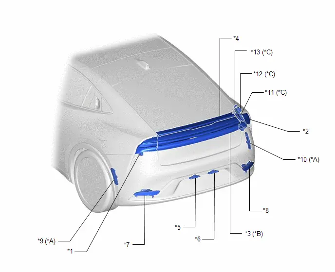
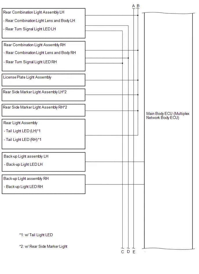
| *A | w/ Rear Side Marker Light | *B | w/ Tail Light LED |
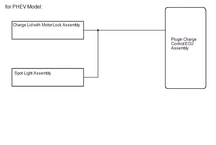
| *C | for PHEV Model | - | - |
| *1 | REAR COMBINATION LIGHT ASSEMBLY LH - REAR COMBINATION LIGHT LENS AND BODY LH - REAR TURN SIGNAL LIGHT LED LH | *2 | REAR COMBINATION LIGHT ASSEMBLY RH - REAR COMBINATION LIGHT LENS AND BODY RH - REAR TURN SIGNAL LIGHT LED RH |
| *3 | REAR LIGHT ASSEMBLY - TAIL LIGHT LED (LH) - TAIL LIGHT LED (RH) | *4 | CENTER STOP LIGHT ASSEMBLY - CENTER STOP LIGHT CORD ASSEMBLY |
| *5 | LICENSE PLATE LIGHT ASSEMBLY (LH) | *6 | LICENSE PLATE LIGHT ASSEMBLY (RH) |
| *7 | BACK-UP LIGHT ASSEMBLY LH - BACK-UP LIGHT LED LH | *8 | BACK-UP LIGHT ASSEMBLY RH - BACK-UP LIGHT LED RH |
| *9 | REAR SIDE MARKER LIGHT ASSEMBLY LH | *10 | REAR SIDE MARKER LIGHT ASSEMBLY RH |
| *11 | PLUGIN CHARGE CONTROL ECU ASSEMBLY | *12 | CHARGE LID WITH MOTOR LOCK ASSEMBLY |
| *13 | SPOT LIGHT ASSEMBLY | - | - |
ILLUSTRATION
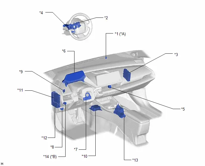
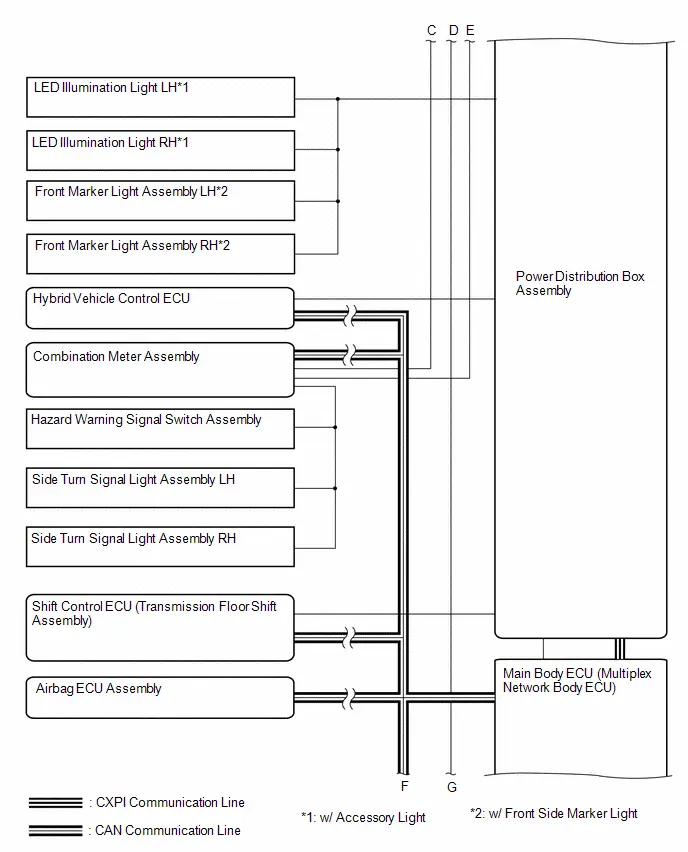
| *A | w/ Automatic Light Control | *B | w/ Manual Leveling System |
| *1 | AUTOMATIC LIGHT CONTROL SENSOR | *2 | STEERING WHEEL SWITCH HOUSING |
| *3 | HYBRID Toyota Prius Vehicle CONTROL ECU | *4 | TURN SIGNAL SWITCH |
| *5 | HAZARD WARNING SIGNAL SWITCH ASSEMBLY | *6 | COMBINATION METER ASSEMBLY |
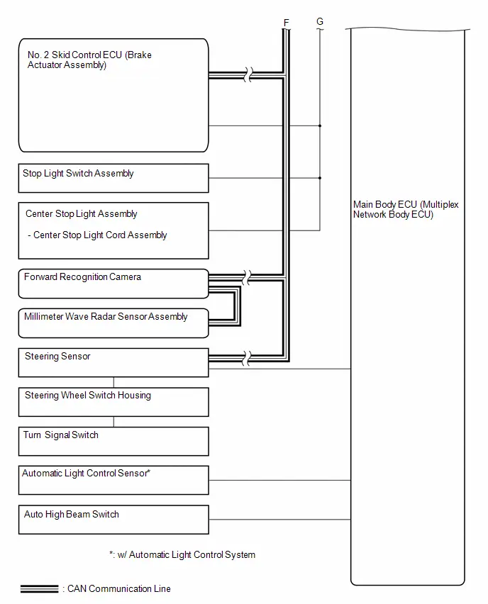
| *7 | STEERING SENSOR | *8 | DLC3 |
| *9 | STOP LIGHT SWITCH ASSEMBLY | *10 | AIRBAG ECU ASSEMBLY |
| *11 | MAIN BODY ECU (MULTIPLEX NETWORK BODY ECU) | *12 | POWER DISTRIBUTION BOX ASSEMBLY - ECU-IGR NO. 1 FUSE - ECU-B NO. 2 FUSE - TAIL FUSE - TAIL RELAY - ECU-B NO. 3 FUSE (for PHEV Model) |
| *13 | SHIFT CONTROL ECU (TRANSMISSION FLOOR SHIFT ASSEMBLY) | *14 | HEADLIGHT LEVELING SWITCH |
System Diagram
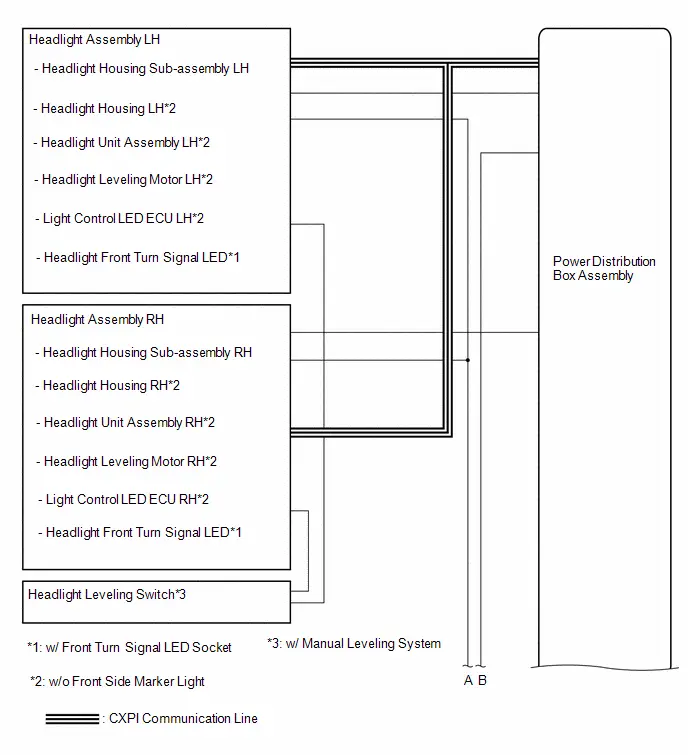
SYSTEM DIAGRAM
How To Proceed With Troubleshooting
CAUTION / NOTICE / HINT
HINT:
- Use the following procedure to troubleshoot the lighting system.
- *: Use the GTS.
PROCEDURE
| 1. | Toyota Prius Vehicle BROUGHT TO WORKSHOP |
|

| 2. | CUSTOMER PROBLEM ANALYSIS |
HINT:
- In troubleshooting, confirm that the problem symptoms have been accurately identified. Preconceptions should be discarded in order to make an accurate judgment. To clearly understand what the problem symptoms are, it is extremely important to ask the customer about the problem and the conditions at the time the malfunction occurred.
- Gather as much information as possible for reference. Past problems that seem unrelated may also help in some cases.
-
The following 5 items are important points for problem analysis:
What
Toyota Prius Vehicle model, system name
When
Date, time, occurrence frequency
Where
Road conditions
Under what conditions?
Driving conditions, weather conditions
How did it happen?
Problem symptoms
|

| 3. | PRE-CHECK |
(a) Measure the auxiliary battery voltage with the ignition switch off.
Standard Voltage:
11 to 14 V
If the voltage is below 11 V, recharge or replace the auxiliary battery before proceeding to the next step.
(b) Check the fuses and relays.
(c) Check the connector connections and terminals to make sure that there are no abnormalities such as loose connections, deformation, etc.
|

| 4. | CHECK COMMUNICATION FUNCTION OF CAN COMMUNICATION SYSTEM* |
(a) Using the GTS, check for CAN communication system DTCs.
for HEV Model: Click here

for PHEV Model: Click here

| Result | Proceed to |
|---|---|
| CAN DTCs are not output | A |
| CAN DTCs are output | B |
| B |

| GO TO CAN COMMUNICATION SYSTEM for HEV Model: Click here
for PHEV Model: Click here
|


|

| 5. | CHECK COMMUNICATION FUNCTION OF CXPI COMMUNICATION SYSTEM* |
(a) Using the GTS, check for CXPI communication system DTCs.
Click here

| Result | Proceed to |
|---|---|
| CAN DTCs are not output | A |
| CAN DTCs are output | B |
| B |

| GO TO CXPI COMMUNICATION SYSTEM |
|

| 6. | CHECK FOR DTC* |
(a) Check for DTCs.
Body Electrical > Main Body > Trouble Codes| Result | Proceed to |
|---|---|
| DTCs are not output | A |
| DTCs are output | B |
| B |

| GO TO DIAGNOSTIC TROUBLE CODE CHART |
|

| 7. | PROBLEM SYMPTOMS TABLE |
(a) Refer to Problem Symptoms Table.
Click here

| Result | Proceed to |
|---|---|
| Fault is not listed in Problem Symptoms Table | A |
| Fault is listed in Problem Symptoms Table | B |
| B |

| GO TO PROBLEM SYMPTOMS TABLE |
|

| 8. | OVERALL ANALYSIS AND TROUBLESHOOTING* |
(a) Operation Check.
Click here

(b) Terminals of ECU.
Click here

(c) Data List / Active Test.
Click here

(d) On-Toyota Prius vehicle Inspection.
(e) Inspection.
|

| 9. | ADJUST, REPAIR OR REPLACE |
|

| 10. | CONFIRMATION TEST |
| NEXT |

| END |
Operation Check
OPERATION CHECK
AUTOMATIC LIGHT CONTROL SYSTEM OPERATION CHECK (w/ Automatic Light Control)
NOTICE:
Make sure that the customize settings are set to default when performing the automatic light control system operation check.
Click here

(a) Turn the ignition switch to ON.
(b) Turn the light control switch to the AUTO position.
(c) Cover the automatic light control sensor.
(d) Check that the taillights and low beam headlights come on.
(e) Uncover the automatic light control sensor.
(f) Check that the low beam headlights and taillights turn off.
LIGHT AUTO TURN-OFF SYSTEM OPERATION CHECK (for Driver Door-linked Auto Light Turn-off System)
(a) Close all of the doors.
(b) Turn the ignition switch to ON.
(c) Turn the taillights, low beam headlights and high beam headlights on.
(d) Turn the ignition switch off.
(e) Open the driver door.
(f) Check that all of the lights turn off immediately.
LIGHT AUTO TURN-OFF SYSTEM OPERATION CHECK (w/ Delay Function)
NOTICE:
Make sure that the customize settings are set to default when performing the light auto turn-off system operation check.
Click here

(a) When the taillights are on (low beam headlights are not on)
(1) Close all of the doors.
(2) Turn the ignition switch to ON.
(3) Turn the taillights on.
(4) Turn the ignition switch off.
(5) Open the driver door.
(6) Check that all of the lights turn off immediately.
(b) When the low beam headlights are on
(1) Close all of the doors.
(2) Turn the ignition switch to ON.
(3) Turn the low beam headlights on.
(4) Turn the ignition switch off.
(5) Open any of the doors.
(6) Close the door.
(7) Check that all of the lights turn off after 30 seconds (delay function).
HINT:
Before the lights turn off, if the lock button on the key is pushed after all of the doors are locked, all of the lights will turn off immediately.
DAYTIME RUNNING LIGHT SYSTEM OPERATION CHECK (w/ Daytime Running Light)
NOTICE:
Make sure that the customize settings are set to default when performing the daytime running light system operation check.*
Click here

*: for Toyota Prius vehicles with customize setting "DRL Function"
(a) Turn the ignition switch to ON (READY).
(b) Turn the light control switch to the tail or AUTO position (with the low beam headlights not turned on via the automatic light control system).
(c) Release the parking brake.
(d) Check that the daytime running lights come on.
NOTICE:
Make sure that the customize settings are set to default when performing the wiper-linked low beam headlight control system operation check.
Click here

WIPER-LINKED LOW BEAM HEADLIGHT CONTROL SYSTEM OPERATION CHECK (w/ Wiper-linked Low Beam Headlight Control System)
(a) Turn the ignition switch to ON.
(b) Shine a light on the automatic light control sensor.
HINT:
If troubleshooting is being performed in a bright area, such as outside on a sunny day, it will not be necessary to perform this step.
(c) Turn the light control switch to the AUTO position.
(d) Operate the front wipers for 10 seconds or more (except MIST or washer-linked wiper operation) and check that the low beam headlights*1 or high beam headlights*2 illuminate.
- *1: Dimmer switch not high position
- *2: Dimmer switch high position
MANUAL HEADLIGHT BEAM LEVEL CONTROL SYSTEM OPERATION CHECK (w/ Manual Leveling System)
(a) Turn the ignition switch to ON (IG).
(b) Turn the headlights on.
(c) Turn the headlight leveling switch to "0".
(d) Check that the headlight beam level changes when the headlight leveling switch is operated.
Customize Parameters
CUSTOMIZE PARAMETERS
CUSTOMIZE LIGHTING SYSTEM (EXT)
NOTICE:
- When the customer requests a change in a function, first make sure that the function can be customized.
- Be sure to make a note of the current settings before customizing.
- When troubleshooting a function, first make sure that the function is set to the default setting.
HINT:
The following items can be customized.
(a) Customizing with the GTS
(1) Enter the following menus: Customize Setting / Light Control, Warning or Illuminated Entry.
(2) Select the setting by referring to the table below.
Light Control| Tester Display | Description | Default | Setting | ECU |
|---|---|---|---|---|
| Tail Remind Buzzer Function | Sounds a buzzer when the driver door is opened with the light control switch in the tail or head position. | Enable | $00:Disable,$01:Enable | Main Body ECU (Multiplex Network Body ECU) |
| Headlight ON in Conjunction with Wiper Function | Turns the low beam headlights on/off according to wiper operation.*1 | Enable | $00:Disable,$01:Enable | Main Body ECU (Multiplex Network Body ECU) |
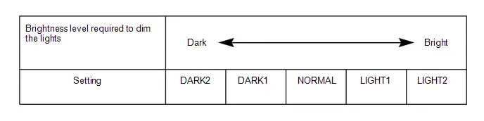
| Brightness Level Adjust (Lowering) | Changes the ambient brightness level required to dim the lights such as the indicator lights of the combination meter, A/C indicator light and clock.*A | Normal | $00:Normal,$01:Dark2,$02:Dark1,$03:Light1,$04:Light2 | Main Body ECU (Multiplex Network Body ECU) |
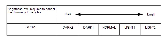
| Brightness Level Adjust (Canceling) | Changes the ambient brightness level required to cancel the dimming of the lights such as the indicator lights of the combination meter, A/C indicator light and clock.*B | Normal | $00:Normal,$01:Dark2,$02:Dark1,$03:Light1,$04:Light2 | Main Body ECU (Multiplex Network Body ECU) |
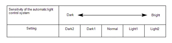
| Sensitivity Adjust | Adjusts the sensitivity of the automatic light control system.*C | Normal | $01:Dark2,$02:Dark1,$00:Normal,$03:Light1,$04:Light2 | Main Body ECU (Multiplex Network Body ECU) |
| Light Auto OFF Delay Setting | Keeps the headlights on for a certain period of time after turning the ignition switch off and closing all of doors with the low beam headlights on.*2 | 30 s | $00:OFF,$01:30sec,$02:60sec,$03:90sec | Main Body ECU (Multiplex Network Body ECU) |
| DRL Function | Turns the DRL function on/off.*3 | Enable | $00:Disable,$01:Enable | Main Body ECU (Multiplex Network Body ECU) |
- *1: w/ Wiper-linked Low Beam Headlight Control System
- *2: w/ Delay Function
- *3: for Toyota Prius vehicles with customize setting "DRL Function"
HINT:
The sensitivity adjustment may be difficult to confirm. Check by driving the vehicle.
-
*A
-
*B
-
*C
| Tester Display | Description | Default | Setting | ECU |
|---|---|---|---|---|
| Lane Change Flashing Times Adjust | Function to change the lane change flashing times. | 3 | $00:OFF,$01:3,$02:4,$03:5,$04:6,$05:7 | Combination Meter Assembly |
(b) Customizing with the multi-display
(1) Enter the following menus:
- Settings (icon) / Toyota Prius Vehicle customize
HINT:
Depending on the specifications of the vehicle, some items may not be displayed.
(2) Select the setting by referring to the table below.
| Display | Default | Content | Setting | Relevant ECU |
|---|---|---|---|---|
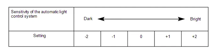
| Headlights Auto-on Sensitivity | Normal | Adjusts the sensitivity of the automatic light control system.*A | Normal, Dark2, Dark1, Light1 or Light2 | Main Body ECU (Multiplex Network Body ECU) |
| Headlights Auto-off Timer*1 | 30 sec. | Keeps the headlights on for a certain period of time after turning the ignition switch off and closing all of doors with the low beam headlights on. | Off, 30 sec., 60 sec. or 90 sec. | Main Body ECU (Multiplex Network Body ECU) |
| Daytime Running Lights*2 | On | Turns the DRL function on/off. | On or Off | Main Body ECU (Multiplex Network Body ECU) |
- *1: w/ Delay Function
- *2: for Toyota Prius vehicles with customize setting "Daytime Running Lights"
HINT:
The sensitivity adjustment may be difficult to confirm. Check by driving the vehicle.
-
*A
Problem Symptoms Table
PROBLEM SYMPTOMS TABLE
NOTICE:
-
Before replacing the main body ECU (multiplex network body ECU), refer to Registration.
Click here

- When replacing the combination meter assembly, always replace it with a new one. If a combination meter assembly which was installed to another Toyota Prius vehicle is used, the information stored in it will not match the information from the vehicle and a DTC may be stored.
-
When replacing the combination meter assembly, update the ECU security key.
Click here

HINT:
Use the table below to help determine the cause of problem symptoms. If multiple suspected areas are listed, the potential causes of the symptoms are listed in order of probability in the "Suspected Area" column of the table. Check each symptom by checking the suspected areas in the order they are listed. Replace parts as necessary.
Headlight| Symptom | Suspected Area | Link |
|---|---|---|
| Left or right low beam headlight does not illuminate | Refer to "LO-beam Headlight does not Illuminate" |
|
| Both left and right low beam headlights do not illuminate | Headlight dimmer switch circuit |
|
| Main body ECU (Multiplex network body ECU) |
| |
| Left or right high beam headlight does not illuminate | High beam headlight circuit |
|
| Both left and right high beam headlights do not illuminate | Headlight dimmer switch circuit |
|
| Main body ECU (Multiplex network body ECU) |
| |
| High Flash (passing function) does not operate (high beam headlights are normal) | Headlight dimmer switch circuit |
|
| Main body ECU (Multiplex network body ECU) |
|


| Symptom | Suspected Area | Link |
|---|---|---|
| Left or right parking light, accessory light or daytime running light do not illuminate | Parking light/daytime running light circuit |
|
| Both left and right parking lights, accessory light or daytime running light do not illuminate | Check customize settings*3 |
|
| Headlight dimmer switch circuit |
| |
| Main body ECU (Multiplex network body ECU) |
|


- *1: w/ Accessory Light
- *2: w/ Daytime Running Light
- *3: for Toyota Prius vehicles with customize setting "DRL Function"
| Symptom | Suspected Area | Link |
|---|---|---|
| Left or right front side marker light does not illuminate | Front marker light assembly |
|
| Harness or connector | - |

| Symptom | Suspected Area | Link |
|---|---|---|
| Left or right accessory light does not illuminate | LED illumination light |
|
| Harness or connector | - | |
| Both left and right accessory lights do not illuminate | Taillight relay circuit |
|
| Harness or connector | - |


| Symptom | Suspected Area | Link |
|---|---|---|
| Left or right taillight (rear combination light assembly) does not illuminate | Rear combination light lens and body |
|
| Harness or connector | - | |
| Left or right taillight (rear light assembly) does not illuminate* | Tail light LED |
|
| Harness or connector | - | |
| All of the taillights, license plate lights and rear side marker lights do not illuminate | Headlight dimmer switch circuit |
|
| Taillight relay circuit |
| |
| Main body ECU (Multiplex network body ECU) |
|


- *: w/ Tail Light LED
| Symptom | Suspected Area | Link |
|---|---|---|
| Left or right rear side marker light does not illuminate | Rear side marker light assembly |
|
| Harness or connector | - |

| Symptom | Suspected Area | Link |
|---|---|---|
| License plate light does not illuminate | License plate light assembly |
|
| Harness or connector | - |

| Symptom | Suspected Area | Link |
|---|---|---|
| Left or right stop light (rear combination light assembly) does not illuminate | Rear combination light lens and body |
|
| Harness or connector | - | |
| All of the stop lights do not illuminate | STOP fuse | - |
| Stop light switch assembly |
| |
| Harness or connector | - |


| Symptom | Suspected Area | Link |
|---|---|---|
| High mounted stop light does not illuminate | Center stop light assembly |
|
| Center stop light cord assembly |
| |
| Harness or connector | - |


| Symptom | Suspected Area | Link |
|---|---|---|
| Left or right back-up light does not illuminate | Back-up light LED |
|
| Harness or connector | - | |
| Both left and right back-up lights do not illuminate | Back-up light circuit |
|


| Symptom | Suspected Area | Link |
|---|---|---|
| Left or right front turn signal light does not operate | Headlight housing sub-assembly*2 |
|
| Headlight front turn signal LED*3 |
| |
| Harness or connector | - | |
| Left or right rear turn signal light does not operate | Rear turn signal light LED |
|
| Harness or connector | - | |
| Left or right side turn signal light does not operate*1 | Side turn signal light assembly |
|
| Outer rear view mirror assembly |
| |
| Harness or connector | - | |
| Turn signal lights do not operate in one direction | Turn signal switch circuit |
|
| Meter/gauge system |
| |
| All turn signal lights do not operate | Turn signal switch circuit |
|
| Combination meter assembly |
| |
| All turn signal lights do not flash at the correct speed | Combination meter assembly |
|


- *1: w/ Side Turn Signal Light
- *2: w/ Front Turn Signal LED Socket
- *3: w/o Front Turn Signal LED Socket
| Symptom | Suspected Area | Link |
|---|---|---|
| Hazard warning signal lights do not operate | Hazard warning switch circuit |
|
| Combination meter assembly |
| |
| Hazard warning signal switch do not flash | Hazard warning switch assembly |
|
| Combination meter assembly |
| |
| Harness or connector | - |


| Symptom | Suspected Area | Link |
|---|---|---|
| Automatic light control system does not operate | Headlight dimmer switch circuit |
|
| Main body ECU (Multiplex network body ECU) |
|


| Symptom | Suspected Area | Link |
|---|---|---|
| Light auto turn-off system does not operate | Headlight dimmer switch circuit |
|
| IG signal circuit |
| |
| Door courtesy switch circuit |
| |
| Main body ECU (Multiplex network body ECU) |
|


| Symptom | Suspected Area | Link |
|---|---|---|
| Wiper-linked low beam headlight control system does not operate | Check customize settings |
|
| Main body ECU (Multiplex network body ECU) |
|


| Symptom | Suspected Area | Link |
|---|---|---|
| Headlight beam level control does not operate | Headlight leveling switch |
|
| Harness or connector | - | |
| Headlight housing sub-assembly |
| |
| Headlight leveling motor* |
|


- *: w/o Front Side Marker Light
| Symptom | Suspected Area | Link |
|---|---|---|
| Charge lid illumination do not illuminate | Refer to the "Charge Lid Illumination Malfunction" |
|

Terminals Of Ecu
TERMINALS OF ECU
CHECK MAIN BODY ECU (MULTIPLEX NETWORK BODY ECU) AND POWER DISTRIBUTION BOX ASSEMBLY
(a) Disconnect the power distribution box assembly and main body ECU (multiplex network body ECU) connectors.
(b) Measure the voltage and resistance according to the value(s) in the table below.
| Terminal No. (Symbol) | Terminal Description | Condition | Specified Condition |
|---|---|---|---|
| z1-13 (GND1) - Body ground | Ground | Always | Below 1 Ω |
| z1-14 (GND2) - Body ground | Ground | Always | Below 1 Ω |
| z1-26 (BECU) - Body ground | Auxiliary battery power supply | Ignition switch off | 11 to 14 V |
| z1-27 (IGR) - Body ground | Ignition power supply (IG signal) | Ignition switch ON | 11 to 14 V |
| Ignition switch off | Below 1 V |
(c) Connect the power distribution box assembly and main body ECU (multiplex network body ECU) connectors.
(d) Measure the voltage and check for pulses according to the value(s) in the table below.
| Terminal No. (Symbol) | Terminal Description | Condition | Specified Condition |
|---|---|---|---|
| K20-30 - Body ground | R shift position switch signal | Ignition switch off, reverse (R) not selected | Below 1 V |
| Ignition switch ON, reverse (R) selected | 11 to 14 V | ||
| A12-5 - Body ground | CXPI communication line | Ignition switch off | Below 1 V |
| Ignition switch ON | Pulse generation | ||
| A12-6 - Body ground | H-LP LH relay drive output |
| 9.5 to 14 V |
| Below 1 V | ||
| A12-10 - Body ground | H-LP RH relay drive output |
| 9.5 to 14 V |
| Below 1 V | ||
| A12-18 - Body ground*1, *2 | Taillights drive output | Taillights off | Below 1 V |
| Taillights on | 11 to 14 V | ||
| R17-30 - Body ground | Taillights drive output | Taillights off | Below 1 V |
| Taillights on | 11 to 14 V | ||
| R17-38 - Body ground | Back-up lights drive output | Ignition switch off, reverse (R) not selected | Below 1 V |
| Ignition switch ON, reverse (R) selected | 11 to 14 V | ||
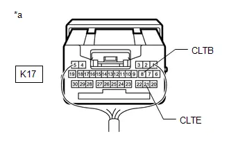
| K17-8 (CLTB) - K17-21 (CLTE) | Automatic light control sensor power supply output | Ignition switch off | Below 1 V |
| Ignition switch ON | 11 to 14 V | ||
| K17-14 (AHBI) - Body ground | Auto high beam switch signal input | Auto high beam switch off | 11 to 14 V |
| Auto high beam switch on | Below 1 V | ||
| K17-15 (AHID) - Body ground | Automatic light control sensor signal input | Ignition switch off | Below 1 V |
| Ignition switch ON | Pulse generation (See waveform 1) | ||
| K17-20 (CLTS) - Body ground | Automatic light control sensor signal input | Ignition switch off | Below 1 V |
| Ignition switch ON | Pulse generation (See waveform 1) | ||
| K17-26 (HEAD) - Body ground | Light control switch head position input | Light control switch not in head position | 11 to 14 V |
| Light control switch in head position | Below 1 V |
- *1: w/ Accessory Light
- *2: w/ Front Side Marker Light
(1) Waveform 1
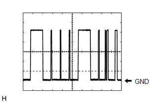
| Item | Content |
|---|---|
| Tester Connection | K17-20 (CLTS) - Body ground |
| Tool setting | 2 V/DIV., 10 ms./DIV. |
| Condition | Ignition switch ON |
HINT:
The communication waveform changes according to the surrounding brightness.
CHECK COMBINATION METER ASSEMBLY
Click here

CHECK STEERING SENSOR
for HEV Model: Click here

for PHEV Model: Click here

CHECK SHIFT CONTROL ECU (TRANSMISSION FLOOR SHIFT ASSEMBLY)
Click here

PLUGIN CHARGE CONTROL ECU ASSEMBLY (for PHEV Model)
Click here

Data List / Active Test
DATA LIST / ACTIVE TEST
DATA LIST
NOTICE:
In the table below, the values listed under "Normal Condition" are reference values. Do not depend solely on these reference values when deciding whether a part is faulty or not.
HINT:
Using the GTS to read the Data List allows the values or states of switches, sensors, actuators and other items to be read without removing any parts. This non-intrusive inspection can be very useful because intermittent conditions or signals may be discovered before parts or wiring is disturbed. Reading the Data List information early in troubleshooting is one way to save diagnostic time.
(a) Read the Data List according to the display on the GTS.
Body Electrical > Main Body > Data List| Tester Display | Measurement Item | Normal Condition | Reference Value | Diagnostic Note |
|---|---|---|---|---|
| Auto High Beam Main Switch | Auto high beam switch signal | OFF or ON | OFF: Auto high beam switch not pressed ON: Auto high beam switch pressed | - |
| Light Control Switch (HEAD) | Light control switch head position signal | OFF or ON | OFF: Light control switch not in head position ON: Light control switch in head position | - |
| Insolation Amount of Solar Sensor RH | Automatic light control sensor RH condition | 0 to 51100 or SensorFail | Condition can be displayed | - |
| Insolation Amount of Solar Sensor LH | Automatic light control sensor LH condition | 0 to 51100 or SensorFail | Condition can be displayed | - |
| Light Sensor Illuminance | Automatic light control sensor illuminance | 0 to 8191 lx or SensorFail | Value is output according to ambient light level | The displayed value is "0" when no light is detected. |
| AHS Function | Adaptive high beam system control function | Not Available or Available | Not Available: Adaptive high beam system control unavailable Available: Adaptive high beam system control valid | Although the item is displayed on the GTS, it is not applicable to this Toyota Prius vehicle. |
| High Beam Headlights (By AHS ECU) | Adaptive high beam system high beam operation status | Light OFF or Light ON | Light OFF: Adaptive high beam system high beam off Light ON: Adaptive high beam system high beam on | Although the item is displayed on the GTS, it is not applicable to this Toyota Prius vehicle. |
| Light Sensor Connection History | Automatic light control sensor connection status | Without or With | Without: Automatic light control sensor has not been connected With: Automatic light control sensor connected or has been connected | - |
| Headlight ECU Function | ECU which controls the lighting system | Not Available or Available | Not Available: Headlight ECU control unavailable Available: Headlight ECU control valid | Although the item is displayed on the GTS, it is not applicable to this Toyota Prius vehicle. |
| LDM ECU Function | ECU which controls the lighting system | Not Available or Available | Not Available: Light control LED ECU control unavailable Available: Light control LED ECU control valid | - |
| Automatic High Beam Headlights Sensor Detection Status | Automatic high beam sensor current state | Undetected, N/A, No sens, Headlight, Taillight, Speed, Daytime, Village, Other sens, Change, Out of aim, SAE Mod, Aim adjust or LIN Err | Condition can be displayed* | If the value of this item is not as specified, the automatic high beam sensor system may be malfunctioning. |
| Communication Power Integration No.1 | Connection status between semiconductor power integration ECU and main body ECU (multiplex network body ECU) | STOP or OK | STOP: No connection OK: Connection | Although the item is displayed on the GTS, it is not applicable to this Toyota Prius vehicle. |
| Communication Power Integration No.2 | Connection status between No. 2 semiconductor power integration ECU and main body ECU (multiplex network body ECU) | STOP or OK | STOP: No connection OK: Connection | Although the item is displayed on the GTS, it is not applicable to this Toyota Prius vehicle. |
| Communication Power Integration No.3 | Connection status between No. 3 semiconductor power integration ECU and main body ECU (multiplex network body ECU) | STOP or OK | STOP: No connection OK: Connection | Although the item is displayed on the GTS, it is not applicable to this Toyota Prius vehicle. |
| Communication Power Distribution Box | Connection status between power distribution box assembly and main body ECU (multiplex network body ECU) | STOP or OK | STOP: No connection OK: Connection | When there is a malfunction, a DTC is stored |
| Communication LDM LH | Connection status between light control LED ECU LH and main body ECU (multiplex network body ECU) | STOP or OK | STOP: No connection OK: Connection | Although the item is displayed on the GTS, it is not applicable to this Toyota Prius vehicle. |
| Communication LDM RH | Connection status between light control LED ECU RH and main body ECU (multiplex network body ECU) | STOP or OK | STOP: No connection OK: Connection | Although the item is displayed on the GTS, it is not applicable to this Toyota Prius vehicle. |
| Tail Remind Buzzer Function | Setting of the tail remind buzzer function on/off | Disable or Enable | Customize setting displayed | - |
| Headlight ON in Conjunction with Wiper Function | Wiper-linked low beam headlight control | Disable or Enable | Customize setting displayed | w/ Wiper-linked Low Beam Headlight Control System |
| Brightness Level Adjust (Lowering) | Ambient brightness level required to dim display lights (combination meter, navigation display, etc.) | Normal, Dark2, Dark1, Light1 or Light2 | Customize setting displayed | - |
| Brightness Level Adjust (Canceling) | Ambient brightness level required to cancel dimming display lights (combination meter, navigation display, etc.) | Normal, Dark2, Dark1, Light1 or Light2 | Customize setting displayed | - |
| Sensitivity Adjust | Sensitivity of the automatic light control system | Normal, Dark2, Dark1, Light1 or Light2 | Customize setting displayed | w/ Automatic Light Control |
| DRL Function | Setting of the DRL function on/off | Disable or Enable | Customize setting displayed | - |
| Light Auto OFF Delay Setting | Light auto OFF delay | OFF, 30sec, 60sec or 90sec | Customize setting displayed | w/ Delay Function |
| Sensitivity Adjust | Sensitivity of the automatic light control system (Driver 1) | Normal, Dark2, Dark1, Light1 or Light2 | Customize setting displayed | w/ Automatic Light Control |
| DRL Function | Setting of the DRL function on/off (Driver 1) | OFF or ON | Customize setting displayed | for Toyota Prius vehicles with customize setting "DRL Function" |
| Light Auto OFF Delay Setting | Light auto OFF delay (Driver 1) | OFF, 30sec, 60sec or 90sec | Customize setting displayed | w/ Delay Function |
| Sensitivity Adjust | Sensitivity of the automatic light control system (Driver 2) | Normal, Dark2, Dark1, Light1 or Light2 | Customize setting displayed | w/ Automatic Light Control |
| DRL Function | Setting of the DRL function on/off (Driver 2) | OFF or ON | Customize setting displayed | for Toyota Prius vehicles with customize setting "DRL Function" |
| Light Auto OFF Delay Setting | Light auto OFF delay (Driver 2) | OFF, 30sec, 60sec or 90sec | Customize setting displayed | w/ Delay Function |
| Sensitivity Adjust | Sensitivity of the automatic light control system (Driver 3) | Normal, Dark2, Dark1, Light1 or Light2 | Customize setting displayed | w/ Automatic Light Control |
| DRL Function | Setting of the DRL function on/off (Driver 3) | OFF or ON | Customize setting displayed | for Toyota Prius vehicles with customize setting "DRL Function" |
| Light Auto OFF Delay Setting | Light auto OFF delay (Driver 3) | OFF, 30sec, 60sec or 90sec | Customize setting displayed | w/ Delay Function |
HINT:
*: The details of each value of the Range are as follows:
| Display Value | Condition | Control Condition | Diagnostic Note |
|---|---|---|---|
| Undetected | Automatic high beam sensor being initialized | Control suspended (low beam headlights illuminated) | - |
| N/A | Automatic high beam sensor temporarily disabled due to high temperature, unclear image (due to dirt, fog, etc.), etc. | Control suspended (previous beam setting maintained) | - |
| No sens | No lights detected | High beam headlights illuminated | Only when Toyota Prius vehicle speed within operation speed range |
| Headlight | Headlights of oncoming vehicle, etc. detected | Low beam headlights illuminated | Only when Toyota Prius vehicle speed within operation speed range |
| Taillight | Taillights preceding vehicle, etc. detected | Low beam headlights illuminated | Only when Toyota Prius vehicle speed within operation speed range |
| Speed | No lights detected and vehicle speed below operation speed | Low beam headlights illuminated | - |
| Daytime | Bright light detected | Low beam headlights illuminated | - |
| Village | Streetlights, etc. detected | Low beam headlights illuminated | Only when Toyota Prius vehicle speed within operation speed range |
| Change | Changing between low beams and high beams | Changing between low beams and high beams | Only when Toyota Prius vehicle speed within operation speed range |
| Other sens | Not applicable | - | - |
| Out of aim | |||
| SAE Mod | |||
| Aim adjust | |||
| LIN Err |
| Tester Display | Measurement Item | Range | Normal Condition | Diagnostic Note |
|---|---|---|---|---|
| Total Distance Traveled | Actual driven distance | 0 to 16777215 | Roughly the same as the actual driven distance | - |
| Total Distance Traveled - Unit | Actual driven distance unit | km or mile | Displays the current actual driven distance unit | - |
| Light OFF Switch | Light control switch DRL OFF*1 or off*2 position signal | OFF or ON | OFF: Light control switch not in DRL OFF*1 or off*2 position ON: Light control switch in DRL OFF*1 or off*2 position | *1, *2 |
| Auto Light Switch | Light control switch AUTO*3 or DRL*4 position signal | OFF or ON | OFF: Light control switch not in AUTO*3 or DRL*4 position ON: Light control switch in AUTO*3 or DRL*4 position | - |
| Head Light Switch (Tail) | Light control switch tail position signal | OFF or ON | OFF: Light control switch in neither tail nor head position ON: Light control switch in tail or head position | - |
| Head Light Switch (Head) | Light control switch head position signal | OFF or ON | OFF: Light control switch not in head position ON: Light control switch in head position | - |
| High Beam Main Switch | Dimmer switch high position signal | OFF or ON | OFF: Dimmer switch not in high position ON: Dimmer switch in high position | - |
| Passing Light Switch | Dimmer switch high flash position (pass) signal | OFF or ON | OFF: Dimmer switch not in high flash position ON: Dimmer switch in high flash position | - |
| Auto High Beam Main Switch | Auto high beam switch signal | OFF or ON | OFF: Auto high beam switch off ON: Auto high beam switch on | Although the item is displayed on the GTS, it is not applicable to this Toyota Prius vehicle. |
| Turn Signal Switch (Right) | Turn signal switch (right turn position) signal | OFF or ON | OFF: Turn signal switch not in right turn position ON: Turn signal switch in right turn position | - |
| Turn Signal Switch (Left) | Turn signal switch (left turn position) signal | OFF or ON | OFF: Turn signal switch not in left turn position ON: Turn signal switch in left turn position | - |
| Cornering Light/Front Side Illuminate Light Switch | Turn signal switch (full turn) signal | OFF or ON | OFF: Turn signal switch not in left or right turn position ON: Turn signal switch in left or right full turn position | - |
| Front Fog Light Switch | Front fog light switch signal | OFF or ON | OFF: Front fog light switch off ON: Front fog light switch on | Although the item is displayed on the GTS, it is not applicable to this Toyota Prius vehicle. |
| Rear Fog Light/Bad Weather Switch | Rear fog light switch signal | OFF or ON | OFF: Rear fog light switch off ON: Rear fog light switch on | Although the item is displayed on the GTS, it is not applicable to this Toyota Prius vehicle. |
| Automatic Light Equipped Info | Automatic light control system specification information | Unknown, With or Without | Unknown: Specification not stored With: Automatic light control system equipped Without: Automatic light control system not equipped | - |
| Bad Weather Mode Equipped Info | Bad weather specification information | Unknown, Without or With | Unknown: Specification not stored Without: Bad weather specification not equipped With: Bad weather specification equipped | Although the item is displayed on the GTS, it is not applicable to this Toyota Prius vehicle. |
- *1: w/ DRL OFF Switch
- *2: w/ OFF Switch
- *3: w/ Automatic Light Control
- *4: w/o Automatic Light Control
| Tester Display | Measurement Item | Range | Normal Condition | Diagnostic Note |
|---|---|---|---|---|
| Turn Signal Switch (Left) | Turn signal switch (left) signal | OFF or ON | OFF: Turn signal switch not in left turn position ON: Turn signal switch in left turn position | Although the item is displayed on the GTS, it is not applicable to this Toyota Prius vehicle. |
| Turn Signal Switch (Right) | Turn signal switch (right) signal | OFF or ON | OFF: Turn signal switch not in right turn position ON: Turn signal switch in right turn position | Although the item is displayed on the GTS, it is not applicable to this Toyota Prius vehicle. |
| Turn Switch Signal (Full Turn) | Turn signal switch (full turn) signal | OFF or ON | OFF: Turn signal switch not in left or right turn position ON: Turn signal switch in left or right turn position | Although the item is displayed on the GTS, it is not applicable to this Toyota Prius vehicle. |
| Hazard Flasher Switch | Hazard warning signal switch signal | OFF or ON | OFF: Hazard warning signal switch off ON: Hazard warning signal switch on | - |
| Lane Change Flashing Times Adjust | Condition of the lane change flashing times | OFF, 3, 4, 5, 6 or 7 | Customize setting displayed | - |
| Tester Display | Measurement Item | Normal Condition | Reference Value | Diagnostic Note |
|---|---|---|---|---|
| Back-up Light Input Signal | Back-up light input | OFF or ON | OFF: Shift lever in any position other than R ON: Shift lever in R | - |
| Back-up Light Output Signal | Back-up light output | OFF or ON | OFF: Back-up light off ON: Back-up light on | - |
| Back-up Light Output Current | Back-up light circuit current | 0.0 to 255.0 A | Below 5.3 A | Back-up light when output is on |
| Back-up Light Fuse Shut Off Status | Back-up light fuse shut off status | OFF or ON | OFF: Fuse has no shut off history ON: Fuse has shut off history | - |
| Back-up Light Fuse Shut Off Count | Back-up light fuse shut off history | 0 to 255 | 0 | - |
| Tail Light Internal Relay Input Signal | Taillight internal relay input | OFF or ON | OFF: Taillights off ON: Taillights on | - |
| Tail Light Internal Relay Output Signal | Taillight internal relay output | OFF or ON | OFF: Taillights off ON: Taillights on | - |
| Tester Display | Measurement Item | Normal Condition | Reference Value | Diagnostic Note |
|---|---|---|---|---|
| Charging Lid Switch Status | EV Charging lid switch status | OFF or ON | ON: Charging port lid open (push lifter of EV charger lid switch assembly extended) OFF: Charging port lid close (push lifter of EV charger lid switch assembly pushed in) | for PHEV Model |
| Charging Lid Lamp Status | Charging lid light status | OFF / Fade Out / ON | OFF: Charging lid light assembly off Fade Out: Charging lid light assembly fading out ON: Charging lid light assembly on | for PHEV Model |
ACTIVE TEST
HINT:
Using the GTS to perform Active Tests allows relays, VSVs, actuators and other items to be operated without removing any parts. This non-intrusive functional inspection can be very useful because intermittent operation may be discovered before parts or wiring is disturbed. Performing Active Tests early in troubleshooting is one way to save diagnostic time. Data List information can be displayed while performing Active Tests.
(a) Perform the Active Test according to the display on the GTS.
Body Electrical > Main Body > Active Test| Tester Display | Measurement Item | Control Range | Diagnostic Note |
|---|---|---|---|
| Headlight Relay / Light Power Supply Relay | Low beam headlights | OFF or ON | - |
| High Beam Headlight | High beam headlights | OFF or ON | - |
| Daytime Running Light | Daytime running lights | OFF or ON | - |
| Automatic High Beam Switch Light | Auto high beam switch indicator light | OFF or ON | - |
| Dimmer Signal | Dimmer signal | OFF or ON | State where circumference illumination is bright. |
| Rear Fog Light | Rear fog lights | OFF or ON | Although the item is displayed on the GTS, it is not applicable to this Toyota Prius vehicle. |
| Taillight / Clearance Light | Taillights/parking lights | OFF or ON | - |
Diagnostic Trouble Code Chart
DIAGNOSTIC TROUBLE CODE CHART
Lighting System| DTC No. | Detection Item | DTC Output from | Priority | Link |
|---|---|---|---|---|
| B124400 | Light Sensor Circuit Malfunction | Main Body | A |
|
| B243900 | Headlight LH Circuit | Main Body | A |
|
| B243A00 | Headlight RH Circuit | Main Body | A |
|
| U010087 | Lost Communication With ECM/PCM "A" Missing Message | Main Body | B |
|
| U010187 | Lost Communication with TCM Missing Message | Main Body | B |
|
| U011187 | Lost Communication with Hybrid/EV Battery Energy Control Module "A" Missing Message | Main Body | B |
|
| U012687 | Lost Communication with Steering Angle Sensor Module Missing Message | Main Body | B |
|
| U012987 | Lost Communication with Brake System Control Module Missing Message | Main Body | B |
|
| U015187 | Lost Communication with Restraints Control Module Missing Message | Main Body | B |
|
| U015587 | Lost Communication with Instrument Panel Cluster (IPC) Control Module Missing Message | Main Body | B |
|
| U016387 | Lost Communication with Navigation Control Module Missing Message | Main Body | B |
|
| U016487 | Lost Communication with HVAC Control Module Missing Message | Main Body | B |
|
| U016887 | Lost Communication with Toyota Prius Vehicle Security Control Module Missing Message | Main Body | B |
|
| U020887 | Lost Communication with "Seat Control Module A" Missing Message | Main Body | B |
|
| U023087 | Lost Communication with Rear Gate Module Missing Message | Main Body | B |
|
| U023A87 | Lost Communication with Image Processing Module "A" Missing Message | Main Body | B |
|
| U023B87 | Lost Communication with Image Processing Module "B" Missing Message | Main Body | B |
|
| U024187 | Lost Communication with Headlamp Control Module "A" Missing Message | Main Body | B |
|
| U026587 | Lost Communication with Image Processing Sensor A Missing Message | Main Body | B |
|
| U029387 | Lost Communication with Hybrid/EV Powertrain Control Module Missing Message | Main Body | B |
|
| U110487 | Lost Communication with Driving Support ECU Missing Message | Main Body | B |
|
| U110687 | Lost Communication with Electric Parking Brake Module Missing Message | Main Body | B |
|
| U110787 | Lost Communication with Power Management Module Missing Message | Main Body | B |
|
| U111087 | Lost Communication with Clearance Sonar Module | Main Body | B |
|
| U111787 | Lost Communication with Accessory Gateway Missing Message | Main Body | B |
|


Light Sensor Circuit Malfunction (B124400)
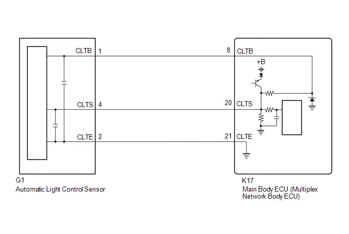
DESCRIPTION
The automatic light control sensor detects ambient light. The sensor creates an electrical signal based on the amount of light detected, and sends the signal to the main body ECU (multiplex network body ECU). The main body ECU (multiplex network body ECU) turns on or off the headlights and taillights according to the signal.
| DTC No. | Detection Item | DTC Detection Condition | Trouble Area | DTC Output from | Priority |
|---|---|---|---|---|---|
| B124400 | Light Sensor Circuit Malfunction | Detection condition:
Malfunction status:
Malfunction duration:
|
| Main Body | A |
WIRING DIAGRAM
CAUTION / NOTICE / HINT
NOTICE:
Before replacing the main body ECU (multiplex network body ECU), refer to Registration.
Click here

PROCEDURE
| 1. | CLEAR DTC |
(a) Clear the DTCs.
Body Electrical > Main Body > Clear DTCs
|

| 2. | CHECK FOR DTC |
Pre-procedure1
(a) Turn the ignition switch to ON.
(b) Wait 10 seconds or more.
Procedure1
(c) Check for DTCs.
Body Electrical > Main Body > Trouble Codes| Result | Proceed to |
|---|---|
| B124400 is not output | A |
| B124400 is output | B |
Post-procedure1
(d) None
| A |

| USE SIMULATION METHOD TO CHECK |
|

| 3. | READ VALUE USING GTS |
Pre-procedure1
(a) Cover the automatic light control sensor with an opaque object.
Procedure1
(b) According to the display on the GTS, read the Data List and check that the value of Light Sensor Illuminance changes while performing the following:
(1) Slowly move the opaque object to uncover and then cover the automatic light control sensor.
Body Electrical > Main Body > Data List| Tester Display | Measurement Item | Normal Condition | Reference Value | Diagnostic Note |
|---|---|---|---|---|
| Light Sensor Illuminance | Automatic light control sensor illuminance | 0 to 8191 lx or SensorFail | Value is output according to ambient light level | The displayed value is "0" when no light is detected. |
| Tester Display |
|---|
| Light Sensor Illuminance |
OK:
The value changes according to the amount the automatic light control sensor is covered.
Post-procedure1
(c) None
| OK |

| REPLACE MAIN BODY ECU (MULTIPLEX NETWORK BODY ECU)
|


|

| 4. | CHECK HARNESS AND CONNECTOR (AUTOMATIC LIGHT CONTROL SENSOR - MAIN BODY ECU (MULTIPLEX NETWORK BODY ECU)) |
Pre-procedure1
(a) Disconnect the G1 automatic light control sensor connector.
(b) Disconnect the K17 main body ECU (multiplex network body ECU) connector.
Procedure1
(c) Measure the resistance according to the value(s) in the table below.
Standard Resistance:
 Click Location & Routing(G1,K17) Click Connector(G1) Click Connector(K17)
 | Tester Connection | Condition | Specified Condition | Result |
|---|---|---|---|
| G1-1 (CLTB) - K17-8 (CLTB) | Always | Below 1 Ω | Ω |
| G1-4 (CLTS) - K17-20 (CLTS) | Always | Below 1 Ω | Ω |
| G1-2 (CLTE) - K17-21 (CLTE) | Always | Below 1 Ω | Ω |
| G1-1 (CLTB) or K17-8 (CLTB) - Body ground | Always | 10 kΩ or higher | kΩ |
| G1-4 (CLTS) or K17-20 (CLTS) - Body ground | Always | 10 kΩ or higher | kΩ |
| G1-2 (CLTE) or K17-21 (CLTE) - Body ground | Always | 10 kΩ or higher | kΩ |
Post-procedure1
(d) None
| NG |

| REPAIR OR REPLACE HARNESS OR CONNECTOR |
|

| 5. | INSPECT MAIN BODY ECU (MULTIPLEX NETWORK BODY ECU) |
Pre-procedure1
(a) Connect the K17 main body ECU (multiplex network body ECU) connector.
Procedure1
| (b) Measure the voltage according to the value(s) in the table below. Standard Voltage:  Click Location & Routing(K17) Click Connector(K17) Click Location & Routing(K17) Click Connector(K17)
Result:
|
|
Post-procedure1
(c) None
| NG |

| REPLACE MAIN BODY ECU (MULTIPLEX NETWORK BODY ECU)
|


|

| 6. | INSPECT AUTOMATIC LIGHT CONTROL SENSOR |
Click here

| OK |

| REPLACE MAIN BODY ECU (MULTIPLEX NETWORK BODY ECU)
|


| NG |

| REPLACE AUTOMATIC LIGHT CONTROL SENSOR |
Headlight LH Circuit (B243900,B243A00)
DESCRIPTION
The light control LED ECU supplies internally boosted voltage to the light control LED ECU so that the current supplied to the LED is always maintained at a constant value.
These DTCs are also output when the main body ECU (multiplex network body ECU) detects malfunctions while monitoring the applied voltage.
| DTC No. | Detection Item | DTC Detection Condition | Trouble Area | DTC Output from | Priority |
|---|---|---|---|---|---|
| B243900 | Headlight LH Circuit | Detection condition:
Malfunction status:
Malfunction duration:
| w/ Front Side Marker Light:
w/o Front Side Marker Light:
| Main Body | A |
| B243A00 | Headlight RH Circuit | Detection condition:
Malfunction status:
Malfunction duration:
| w/ Front Side Marker Light:
w/o Front Side Marker Light:
| Main Body | A |
WIRING DIAGRAM

HEADLIGHT ASSEMBLY CIRCUIT (w/o Front Side Marker Light)

CAUTION / NOTICE / HINT
NOTICE:
- Inspect the fuses for circuits related to this system before performing the following procedure.
-
Before replacing the main body ECU (multiplex network body ECU), refer to Registration.
Click here

-
First perform the communication function inspections in How to Proceed with Troubleshooting to confirm that there are no CXPI communication malfunctions before troubleshooting this symptom.
Click here


PROCEDURE
| 1. | CONFIRM MODEL |
(a) Choose the model to be inspected.
| Result | Proceed to |
|---|---|
| w/ Front Side Marker Light | A |
| w/o Front Side Marker Light | B |
| B |

| GO TO STEP 12 |
|

| 2. | CLEAR DTC |
(a) Clear the DTCs.
Body Electrical > Main Body > Clear DTCs
|

| 3. | CHECK FOR DTC |
Pre-procedure1
(a) Turn the ignition switch to ON.
(b) Operate the light control switch to turn on the low beam headlights and wait 10 seconds or more.
Procedure1
(c) Check for DTCs.
Body Electrical > Main Body > Trouble Codes| Result | Proceed to |
|---|---|
| B243900 is not output | A |
| B243900 is output | B |
Post-procedure1
(d) None
| B |

| GO TO STEP 9 |
|

| 4. | CLEAR DTC |
(a) Clear the DTCs.
Body Electrical > Main Body > Clear DTCs
|

| 5. | CHECK FOR DTC |
Pre-procedure1
(a) Turn the ignition switch to ON.
(b) Operate the light control switch to turn on the low beam headlights and wait 10 seconds or more.
Procedure1
(c) Check for DTCs.
Body Electrical > Main Body > Trouble Codes| Result | Proceed to |
|---|---|
| B243A00 is not output | A |
| B243A00 is output | B |
Post-procedure1
(d) None
| A |

| USE SIMULATION METHOD TO CHECK |
|

| 6. | CHECK HEADLIGHT HOUSING SUB-ASSEMBLY RH |
(a) Interchange the headlight housing sub-assembly RH with LH and connect the connectors.
HINT:
Click here

|

| 7. | CLEAR DTC |
(a) Clear the DTCs.
Body Electrical > Main Body > Clear DTCs
|

| 8. | CHECK FOR DTC |
Pre-procedure1
(a) Turn the ignition switch to ON.
(b) Operate the light control switch to turn on the low beam headlights and wait 10 seconds or more.
Procedure1
(c) Check for DTCs.
Body Electrical > Main Body > Trouble Codes| Result | Proceed to |
|---|---|
| B243A00 is output | A |
| B243A00 is not output | B |
Post-procedure1
(d) None
| A |

| REPLACE MAIN BODY ECU (MULTIPLEX NETWORK BODY ECU)
|


| B |

| REPLACE HEADLIGHT HOUSING SUB-ASSEMBLY RH |
| 9. | CHECK HEADLIGHT HOUSING SUB-ASSEMBLY LH |
(a) Interchange the headlight housing sub-assembly LH with RH and connect the connectors.
HINT:
Click here

|

| 10. | CLEAR DTC |
(a) Clear the DTCs.
Body Electrical > Main Body > Clear DTCs
|

| 11. | CHECK FOR DTC |
Pre-procedure1
(a) Turn the ignition switch to ON.
(b) Operate the light control switch to turn on the low beam headlights and wait 10 seconds or more.
Procedure1
(c) Check for DTCs.
Body Electrical > Main Body > Trouble Codes| Result | Proceed to |
|---|---|
| B243900 is output | A |
| B243900 is not output | B |
Post-procedure1
(d) None
| A |

| REPLACE MAIN BODY ECU (MULTIPLEX NETWORK BODY ECU)
|


| B |

| REPLACE HEADLIGHT HOUSING SUB-ASSEMBLY LH |
| 12. | CLEAR DTC |
(a) Clear the DTCs.
Body Electrical > Main Body > Clear DTCs
|

| 13. | CHECK FOR DTC |
Pre-procedure1
(a) Turn the ignition switch to ON.
(b) Operate the light control switch to turn on the low beam headlights and wait 10 seconds or more.
Procedure1
(c) Check for DTCs.
Body Electrical > Main Body > Trouble Codes| Result | Proceed to |
|---|---|
| B243900 is not output | A |
| B243900 is output | B |
Post-procedure1
(d) None
| B |

| GO TO STEP 21 |
|

| 14. | CLEAR DTC |
(a) Clear the DTCs.
Body Electrical > Main Body > Clear DTCs
|

| 15. | CHECK FOR DTC |
Pre-procedure1
(a) Turn the ignition switch to ON.
(b) Operate the light control switch to turn on the low beam headlights and wait 10 seconds or more.
Procedure1
(c) Check for DTCs.
Body Electrical > Main Body > Trouble Codes| Result | Proceed to |
|---|---|
| B243A00 is not output | A |
| B243A00 is output | B |
Post-procedure1
(d) None
| A |

| USE SIMULATION METHOD TO CHECK |
|

| 16. | CHECK HEADLIGHT HOUSING SUB-ASSEMBLY RH |
(a) Interchange the headlight housing sub-assembly RH with LH and connect the connectors.
HINT:
Click here

|

| 17. | CLEAR DTC |
(a) Clear the DTCs.
Body Electrical > Main Body > Clear DTCs
|

| 18. | CHECK FOR DTC |
Pre-procedure1
(a) Turn the ignition switch to ON.
(b) Operate the light control switch to turn on the low beam headlights and wait 10 seconds or more.
Procedure1
(c) Check for DTCs.
Body Electrical > Main Body > Trouble Codes| Result | Proceed to |
|---|---|
| B243900 is not output | A |
| B243900 is output | B |
Post-procedure1
(d) None
| A |

| REPLACE MAIN BODY ECU (MULTIPLEX NETWORK BODY ECU)
|


|

| 19. | INSPECT LIGHT CONTROL LED ECU RH |
Pre-procedure1
(a) Remove the headlight housing sub-assembly RH.
HINT:
Click here

Procedure1
| (b) Measure the voltage according to the value(s) in the table below. Standard Voltage:
Result:
|
|
Post-procedure1
(c) None
| NG |

| REPLACE LIGHT CONTROL LED ECU RH |
|

| 20. | INSPECT HEADLIGHT HOUSING RH |
Pre-procedure1
(a) Remove the headlight housing sub-assembly RH.
HINT:
Click here

(b) Disconnect the light control LED ECU RH connector.
(c) Disconnect the headlight unit assembly RH connector.
Procedure1
(d) Measure the resistance according to the value(s) in the table below.

| *a | Component without harness connected (to Light Control LED ECU RH) | *b | Component without harness connected (to Headlight Unit assembly RH) |
Standard Resistance:
| Tester Connection | Condition | Specified Condition | Result |
|---|---|---|---|
| A-16 - B-1 | Always | Below 1 Ω | Ω |
| A-4 - B-4 | Always | Below 1 Ω | Ω |
Post-procedure1
(e) None
| OK |

| REPLACE HEADLIGHT UNIT ASSEMBLY RH |
| NG |

| REPLACE HEADLIGHT HOUSING RH |
| 21. | CHECK HEADLIGHT HOUSING SUB-ASSEMBLY LH |
(a) Interchange the headlight housing sub-assembly LH with RH and connect the connectors.
HINT:
Click here

|

| 22. | CLEAR DTC |
(a) Clear the DTCs.
Body Electrical > Main Body > Clear DTCs
|

| 23. | CHECK FOR DTC |
Pre-procedure1
(a) Turn the ignition switch to ON.
(b) Operate the light control switch to turn on the low beam headlights and wait 10 seconds or more.
Procedure1
(c) Check for DTCs.
Body Electrical > Main Body > Trouble Codes| Result | Proceed to |
|---|---|
| B243900 is output | A |
| B243900 is not output | B |
Post-procedure1
(d) None
| A |

| REPLACE MAIN BODY ECU (MULTIPLEX NETWORK BODY ECU)
|


|

| 24. | INSPECT LIGHT CONTROL LED ECU LH |
Procedure1
(a) Remove the headlight housing sub-assembly LH.
HINT:
Click here

Post-procedure1

| *a | Component with harness connected (Light Control LED ECU LH) |
(b) Measure the voltage according to the value(s) in the table below.
Standard Voltage:
| Tester Connection | Condition | Specified Condition | Result |
|---|---|---|---|
| A-16 - A-4 | Light control switch in HEAD position | 10 to 16 V | V |
Pre-procedure1
(c) None
| NG |

| REPLACE LIGHT CONTROL LED ECU LH |
|

| 25. | INSPECT HEADLIGHT HOUSING LH |
Pre-procedure1
(a) Remove the headlight housing sub-assembly LH.
HINT:
Click here

(b) Disconnect the light control LED ECU LH connector.
(c) Disconnect the headlight unit assembly LH connector.
Procedure1
(d) Measure the resistance according to the value(s) in the table below.

| *a | Component without harness connected (to Light Control LED ECU LH) | *b | Component without harness connected (to Headlight Unit assembly LH) |
Standard Resistance:
| Tester Connection | Condition | Specified Condition | Result |
|---|---|---|---|
| A-16 - B-1 | Always | Below 1 Ω | Ω |
| A-4 - B-4 | Always | Below 1 Ω | Ω |
Post-procedure1
(e) None
| OK |

| REPLACE HEADLIGHT UNIT ASSEMBLY LH |
| NG |

| REPLACE HEADLIGHT HOUSING LH |
Lost Communication With ECM/PCM "A" Missing Message (U010087,...,U111787)
DESCRIPTION
These DTCs are stored if a CAN communication malfunction occurs between the main body ECU (multiplex network body ECU) and other ECUs.
| DTC No. | Detection Item | DTC Detection Condition | Trouble Area | DTC Output from | Priority |
|---|---|---|---|---|---|
| U010087 | Lost Communication With ECM/PCM "A" Missing Message | The main body ECU (multiplex network body ECU) does not receive data from the ECM for approximately 10 seconds or more. | CAN communication system | Main Body | B |
| U010187 | Lost Communication with TCM Missing Message | The main body ECU (multiplex network body ECU) does not receive data from the hybrid Toyota Prius vehicle control ECU for approximately 10 seconds or more. | CAN communication system | Main Body | B |
| U011187 | Lost Communication with Hybrid/EV Battery Energy Control Module "A" Missing Message | The main body ECU (multiplex network body ECU) does not receive data from the hybrid Toyota Prius vehicle control ECU for approximately 10 seconds or more. | CAN communication system | Main Body | B |
| U012687 | Lost Communication with Steering Angle Sensor Module Missing Message | The main body ECU (multiplex network body ECU) does not receive data from the steering sensor for approximately 10 seconds or more. | CAN communication system | Main Body | B |
| U012987 | Lost Communication with Brake System Control Module Missing Message | The main body ECU (multiplex network body ECU) does not receive data from the No. 2 skid control ECU (brake actuator assembly) for approximately 10 seconds or more. | CAN communication system | Main Body | B |
| U015187 | Lost Communication with Restraints Control Module Missing Message | The main body ECU (multiplex network body ECU) does not receive data from the airbag sensor assembly for approximately 10 seconds or more. | CAN communication system | Main Body | B |
| U015587 | Lost Communication with Instrument Panel Cluster (IPC) Control Module Missing Message | The main body ECU (multiplex network body ECU) does not receive data from the combination meter assembly for approximately 10 seconds or more. | CAN communication system | Main Body | B |
| U016387 | Lost Communication with Navigation Control Module Missing Message | The main body ECU (multiplex network body ECU) does not receive data from the radio receiver assembly for approximately 10 seconds or more. | CAN communication system | Main Body | B |
| U016487 | Lost Communication with HVAC Control Module Missing Message | The main body ECU (multiplex network body ECU) does not receive data from the air conditioning amplifier assembly for approximately 10 seconds or more. | CAN communication system | Main Body | B |
| U016887 | Lost Communication with Toyota Prius Vehicle Security Control Module Missing Message | The main body ECU (multiplex network body ECU) does not receive data from the certification ECU (smart key ECU assembly) for approximately 10 seconds or more. | CAN communication system | Main Body | B |
| U020887 | Lost Communication with "Seat Control Module A" Missing Message | The main body ECU (multiplex network body ECU) does not receive data from the position control ECU assembly for approximately 10 seconds or more. | CAN communication system | Main Body | B |
| U023087 | Lost Communication with Rear Gate Module Missing Message | The main body ECU (multiplex network body ECU) does not receive data from the multiplex network door ECU for approximately 10 seconds or more. | CAN communication system | Main Body | B |
| U023A87 | Lost Communication with Image Processing Module "A" Missing Message | The main body ECU (multiplex network body ECU) does not receive data from the forward recognition camera for approximately 10 seconds or more. | CAN communication system | Main Body | B |
| U023B87 | Lost Communication with Image Processing Module "B" Missing Message | The main body ECU (multiplex network body ECU) does not receive data from the clearance warning ECU assembly for approximately 10 seconds or more. | CAN communication system | Main Body | B |
| U024187 | Lost Communication with Headlamp Control Module "A" Missing Message | The main body ECU (multiplex network body ECU) does not receive data from the headlight ECU sub-assembly LH for approximately 10 seconds or more. | CAN communication system | Main Body | B |
| U026587 | Lost Communication with Image Processing Sensor A Missing Message | The main body ECU (multiplex network body ECU) does not receive data from the rear television camera assembly for approximately 10 seconds or more. | CAN communication system | Main Body | B |
| U029387 | Lost Communication with Hybrid/EV Powertrain Control Module Missing Message | The main body ECU (multiplex network body ECU) does not receive data from the hybrid Toyota Prius vehicle control ECU for approximately 10 seconds or more. | CAN communication system | Main Body | B |
| U110487 | Lost Communication with Driving Support ECU Missing Message | The main body ECU (multiplex network body ECU) does not receive data from the forward recognition camera for approximately 10 seconds or more. | CAN communication system | Main Body | B |
| U110687 | Lost Communication with Electric Parking Brake Module Missing Message | The main body ECU (multiplex network body ECU) does not receive data from the No. 2 skid control ECU (brake actuator assembly) for approximately 10 seconds or more. | CAN communication system | Main Body | B |
| U110787 | Lost Communication with Power Management Module Missing Message | The main body ECU (multiplex network body ECU) does not receive data from the certification ECU (smart key ECU assembly) for approximately 10 seconds or more. | CAN communication system | Main Body | B |
| U111087 | Lost Communication with Clearance Sonar Module | The main body ECU (multiplex network body ECU) does not receive data from the clearance warning ECU assembly for approximately 10 seconds or more. | CAN communication system | Main Body | B |
| U111787 | Lost Communication with Accessory Gateway Missing Message | The main body ECU (multiplex network body ECU) does not receive data from the option connector (bus buffer ECU) for approximately 10 seconds or more. | CAN communication system | Main Body | B |
PROCEDURE
| 1. | CLEAR DTC |
(a) Clear the DTCs.
Body Electrical > Main Body > Clear DTCs
|

| 2. | CHECK FOR DTC |
Pre-procedure1
(a) Turn the ignition switch to ON.
(b) Wait 20 seconds or more.
Procedure1
(c) Check for DTCs.
Body Electrical > Main Body > Trouble Codes| Result | Proceed to |
|---|---|
| DTCs are not output | A |
| U010087, U010187, U011187, U012687, U012987, U015187, U015587, U016387, U016487, U016887, U020887, U023087, U023A87, U023B87, U024187, U026587, U029387, U110487, U110687, U110787, U111087 or U111787 is output | B |
Post-procedure1
(d) None
| A |

| USE SIMULATION METHOD TO CHECK |
| B |

| GO TO CAN COMMUNICATION SYSTEM for HEV Model: Click here
for PHEV Model: Click here
|


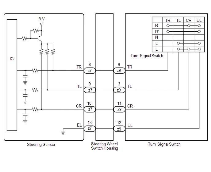
Turn Signal Switch Circuit
DESCRIPTION
The steering sensor receives the turn signal switch information and controls the turn signal lights.
WIRING DIAGRAM
PROCEDURE
| 1. | READ VALUE USING GTS |
(a) Read the Data List according to the display on the GTS.
Chassis > Steering Angle Sensor > Data List| Tester Display | Measurement Item | Range | Normal Condition | Diagnostic Note |
|---|---|---|---|---|
| Turn Signal Switch (Right) | Turn signal switch (right turn position) signal | OFF or ON | OFF: Turn signal switch not in right turn position ON: Turn signal switch in right turn position | - |
| Turn Signal Switch (Left) | Turn signal switch (left turn position) signal | OFF or ON | OFF: Turn signal switch not in left turn position ON: Turn signal switch in left turn position | - |
| Cornering Light/Front Side Illuminate Light Switch | Turn signal switch (full turn) signal | OFF or ON | OFF: Turn signal switch not in left or right turn position ON: Turn signal switch in left or right full turn position | - |
| Tester Display |
|---|
| Turn Signal Switch (Right) |
| Turn Signal Switch (Left) |
| Cornering Light/Front Side Illuminate Light Switch |
OK:
Normal conditions listed above are displayed.
| OK |

| PROCEED TO NEXT SUSPECTED AREA SHOWN IN PROBLEM SYMPTOMS TABLE
|


|

| 2. | INSPECT TURN SIGNAL SWITCH |
Click here

| NG |

| REPLACE TURN SIGNAL SWITCH |
|

| 3. | INSPECT STEERING WHEEL SWITCH HOUSING |
Click here

| OK |

| REPLACE STEERING SENSOR
|


| NG |

| REPLACE STEERING WHEEL SWITCH HOUSING
|


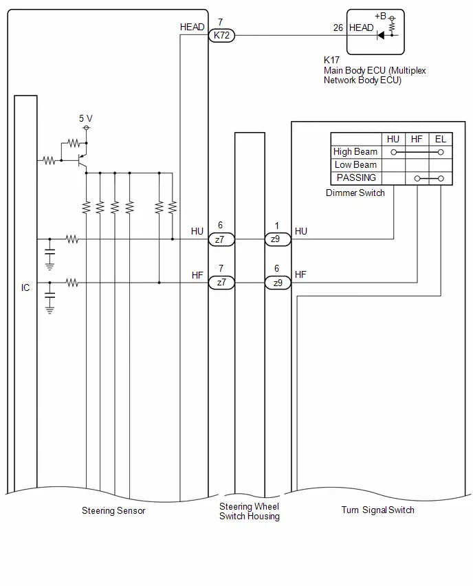
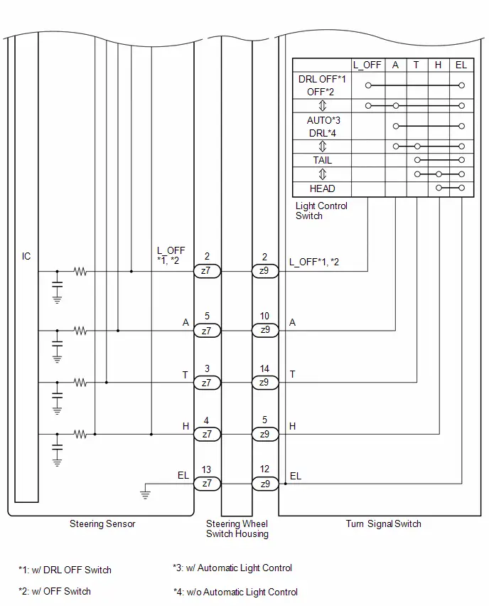
Headlight Dimmer Switch Circuit
DESCRIPTION
The steering sensor receives the following switch information:
- Light control switch in DRL OFF*1, OFF*2, tail, head, AUTO*3 or DRL*4 position
-
Dimmer switch in high, low or high flash (pass) position
- *1: w/ DRL OFF Switch
- *2: w/ OFF Switch
- *3: w/ Automatic Light Control
- *4: w/o Automatic Light Control
WIRING DIAGRAM
CAUTION / NOTICE / HINT
NOTICE:
-
Before replacing the main body ECU (multiplex network body ECU), refer to Registration.
Click here

PROCEDURE
| 1. | READ VALUE USING GTS |
(a) Read the Data List according to the display on the GTS.
Chassis > Steering Angle Sensor > Data List| Tester Display | Measurement Item | Normal Condition | Reference Value | Diagnostic Note |
|---|---|---|---|---|
| Light OFF Switch | Light control switch DRL OFF*1 or off*2 position signal | OFF or ON | OFF: Light control switch not in DRL OFF*1 or off*2 position ON: Light control switch in DRL OFF*1 or off*2 position | *1, *2 |
| Auto Light Switch | Light control switch AUTO*3 or DRL*4 position signal | OFF or ON | OFF: Light control switch not in AUTO*3 or DRL*4 position ON: Light control switch in AUTO*3 or DRL*4 position | - |
| Head Light Switch (Tail) | Light control switch tail position signal | OFF or ON | OFF: Light control switch in neither tail nor head position ON: Light control switch in tail or head position | - |
| Head Light Switch (Head) | Light control switch head position signal | OFF or ON | OFF: Light control switch not in head position ON: Light control switch in head position | - |
| High Beam Main Switch | Dimmer switch high position signal | OFF or ON | OFF: Dimmer switch not in high position ON: Dimmer switch in high position | - |
| Passing Light Switch | Dimmer switch high flash position (pass) signal | OFF or ON | OFF: Dimmer switch not in high flash position ON: Dimmer switch in high flash position | - |
| Tester Display |
|---|
| Light OFF Switch |
| Auto Light Switch |
| Head Light Switch (Tail) |
| Head Light Switch (Head) |
| High Beam Main Switch |
| Passing Light Switch |
OK:
Normal conditions listed above are displayed.
- *1: w/ DRL OFF Switch
- *2: w/ OFF Switch
- *3: w/ Automatic Light Control
- *4: w/o Automatic Light Control
| NG |

| GO TO STEP 5 |
|

| 2. | READ VALUE USING GTS |
(a) Read the Data List according to the display on the GTS.
Body Electrical > Main Body > Data List| Tester Display | Measurement Item | Normal Condition | Reference Value | Diagnostic Note |
|---|---|---|---|---|
| Light Control Switch (HEAD) | Light control switch head position signal | OFF or ON | OFF: Light control switch not in head position ON: Light control switch in head position | - |
| Tester Display |
|---|
| Light Control Switch (HEAD) |
OK:
Normal conditions listed above are displayed.
| OK |

| PROCEED TO NEXT SUSPECTED AREA SHOWN IN PROBLEM SYMPTOMS TABLE
|


|

| 3. | INSPECT STEERING SENSOR |
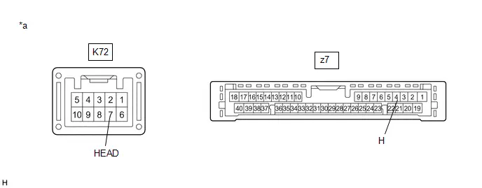
| *a | Component without harness connected (Steering Sensor) | - | - |
(a) Remove the steering sensor.
Click here


(b) Measure the resistance according to the value(s) in the table below.
Standard Resistance:
 Click Location & Routing(K72,z7) Click Connector(K72) Click Connector(z7)
 | Tester Connection | Condition | Specified Condition |
|---|---|---|
| K72-7 (HEAD) - z7-4 (H) | Always | Below 1 Ω |
| NG |

| REPLACE STEERING SENSOR
|


|

| 4. | CHECK HARNESS AND CONNECTOR (STEERING SENSOR - MAIN BODY ECU (MULTIPLEX NETWORK BODY ECU)) |
(a) Disconnect the K17 main body ECU (multiplex network body ECU) connector.
(b) Measure the resistance according to the value(s) in the table below.
Standard Resistance:
 Click Location & Routing(K72,K17) Click Connector(K72) Click Connector(K17)
 | Tester Connection | Condition | Specified Condition |
|---|---|---|
| K72-7 (HEAD) - K17-26 (HEAD) | Always | Below 1 Ω |
| K72-7 (HEAD) or K17-26 (HEAD) - Body ground | Always | 10 kΩ or higher |
| OK |

| REPLACE MAIN BODY ECU (MULTIPLEX NETWORK BODY ECU)
|


| NG |

| REPAIR OR REPLACE HARNESS OR CONNECTOR |
| 5. | INSPECT TURN SIGNAL SWITCH |
Click here

| NG |

| REPLACE TURN SIGNAL SWITCH |
|

| 6. | INSPECT STEERING WHEEL SWITCH HOUSING |
Click here

| OK |

| REPLACE STEERING SENSOR
|


| NG |

| REPLACE STEERING WHEEL SWITCH HOUSING
|


Parking Light/Daytime Running Light Circuit
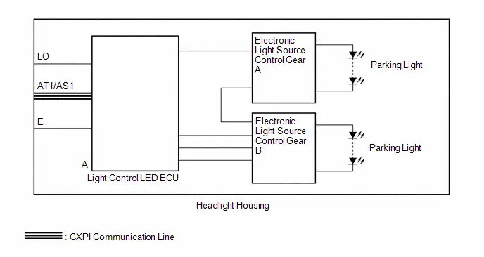
DESCRIPTION
The main body ECU (multiplex network body ECU) controls the parking lights and daytime running lights*.
- *: w/o Front Turn Signal LED Socket
WIRING DIAGRAM

HEADLIGHT ASSEMBLY CIRCUIT (w/o Front Side Marker Light)
CAUTION / NOTICE / HINT
NOTICE:
- Inspect the fuses for circuits related to this system before performing the following procedure.
-
Before replacing the main body ECU (multiplex network body ECU), refer to Registration.
Click here

-
First perform the communication function inspections in How to Proceed with Troubleshooting to confirm that there are no CXPI communication malfunctions before troubleshooting this symptom.
Click here


PROCEDURE
| 1. | CONFIRM MODEL |
(a) Choose the model to be inspected.
| Result | Proceed to |
|---|---|
| w/o Front Turn Signal LED Socket | A |
| w/ Front Turn Signal LED Socket | B |
| B |

| GO TO STEP 3 |
|

| 2. | PERFORM ACTIVE TEST USING GTS |
(a) Perform the Active Test according to the display on the GTS.
Body Electrical > Main Body > Active Test| Tester Display | Measurement Item | Control Range | Diagnostic Note |
|---|---|---|---|
| Daytime Running Light | Daytime running lights | OFF or ON | - |
| Taillight / Clearance Light | Taillights/parking lights | OFF or ON | - |
| Tester Display |
|---|
| Daytime Running Light |
| Tester Display |
|---|
| Taillight / Clearance Light |
OK:
Parking lights and daytime running lights illuminate.
| Result | Proceed to |
|---|---|
| OK | A |
| NG (LH side parking light or daytime running light does not illuminate) | B |
| NG (RH side parking light or daytime running light does not illuminate) | C |
| A |

| PROCEED TO NEXT SUSPECTED AREA SHOWN IN PROBLEM SYMPTOMS TABLE
|


| B |

| REPLACE HEADLIGHT HOUSING SUB-ASSEMBLY LH |
| C |

| REPLACE HEADLIGHT HOUSING SUB-ASSEMBLY RH |
| 3. | CONFIRM MODEL |
(a) Choose the model to be inspected.
| Result | Proceed to |
|---|---|
| w/ Front Side Marker Light | A |
| w/o Front Side Marker Light | B |
| B |

| GO TO STEP 5 |
|

| 4. | PERFORM ACTIVE TEST USING GTS |
(a) Perform the Active Test according to the display on the GTS.
Body Electrical > Main Body > Active Test| Tester Display | Measurement Item | Control Range | Diagnostic Note |
|---|---|---|---|
| Taillight / Clearance Light | Taillights/parking lights | OFF or ON | - |
| Tester Display |
|---|
| Taillight / Clearance Light |
OK:
Parking lights illuminate.
| Result | Proceed to |
|---|---|
| OK | A |
| NG (LH side parking light does not illuminate) | B |
| NG (RH side parking light does not illuminate) | C |
| A |

| PROCEED TO NEXT SUSPECTED AREA SHOWN IN PROBLEM SYMPTOMS TABLE
|


| B |

| REPLACE HEADLIGHT HOUSING SUB-ASSEMBLY LH |
| C |

| REPLACE HEADLIGHT HOUSING SUB-ASSEMBLY RH |
| 5. | PERFORM ACTIVE TEST USING GTS |
(a) Perform the Active Test according to the display on the GTS.
Body Electrical > Main Body > Active Test| Tester Display | Measurement Item | Control Range | Diagnostic Note |
|---|---|---|---|
| Taillight / Clearance Light | Taillights/parking lights | OFF or ON | - |
| Tester Display |
|---|
| Taillight / Clearance Light |
OK:
Parking lights illuminate.
| Result | Proceed to |
|---|---|
| OK | A |
| NG (LH side parking light does not illuminate) | B |
| NG (RH side parking light does not illuminate) | C |
| A |

| PROCEED TO NEXT SUSPECTED AREA SHOWN IN PROBLEM SYMPTOMS TABLE
|


| C |

| GO TO STEP 8 |
|

| 6. | CHECK LIGHT CONTROL LED ECU LH |
(a) Interchange the light control LED ECU LH with RH and connect the connectors.
Click here

|

| 7. | CHECK OPERATION (PARKING LIGHTS) |
(a) Check the operation of the parking lights of the headlight housing sub-assembly LH.
OK:
The parking lights of the headlight housing sub-assembly LH operate normally.
| OK |

| REPLACE LIGHT CONTROL LED ECU LH |
| NG |

| REPLACE HEADLIGHT HOUSING SUB-ASSEMBLY LH |
| 8. | CHECK LIGHT CONTROL LED ECU RH |
(a) Interchange the light control LED ECU RH with LH and connect the connectors.
Click here

|

| 9. | CHECK OPERATION (PARKING LIGHTS) |
(a) Check the operation of the parking lights of the headlight housing sub-assembly RH.
OK:
The parking lights of the headlight housing sub-assembly RH operate normally.
| OK |

| REPLACE LIGHT CONTROL LED ECU RH |
| NG |

| REPLACE HEADLIGHT HOUSING SUB-ASSEMBLY RH |
Hazard Warning Switch Circuit
DESCRIPTION
The combination meter assembly receives the hazard warning signal switch assembly on signal and controls the operation of the hazard warning lights.
WIRING DIAGRAM
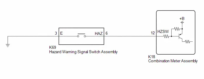
CAUTION / NOTICE / HINT
NOTICE:
- When replacing the combination meter assembly, always replace it with a new one. If a combination meter assembly which was installed to another Toyota Prius vehicle is used, the information stored in it will not match the information from the vehicle and a DTC may be stored.
-
When replacing the combination meter assembly, update the ECU security key.
Click here

PROCEDURE
| 1. | READ VALUE USING GTS |
(a) Read the Data List according to the display on the GTS.
Body Electrical > Combination Meter > Data List| Tester Display | Measurement Item | Range | Normal Condition | Diagnostic Note |
|---|---|---|---|---|
| Hazard Flasher Switch | Hazard warning signal switch signal | OFF or ON | OFF: Hazard warning signal switch off ON: Hazard warning signal switch on | - |
| Tester Display |
|---|
| Hazard Flasher Switch |
OK:
Normal conditions listed above are displayed.
| OK |

| PROCEED TO NEXT SUSPECTED AREA SHOWN IN PROBLEM SYMPTOMS TABLE
|


|

| 2. | INSPECT HAZARD WARNING SIGNAL SWITCH ASSEMBLY |
Click here

| NG |

| REPLACE HAZARD WARNING SIGNAL SWITCH ASSEMBLY |
|

| 3. | CHECK HARNESS AND CONNECTOR (HAZARD WARNING SIGNAL SWITCH ASSEMBLY - COMBINATION METER ASSEMBLY AND BODY GROUND) |
(a) Disconnect the K18 combination meter assembly connector.
(b) Measure the resistance according to the value(s) in the table below.
Standard Resistance:
 Click Location & Routing(K18,K69) Click Connector(K18) Click Connector(K69)
 | Tester Connection | Condition | Specified Condition |
|---|---|---|
| K18-12 (HZSW) - K69-6 (HAZ) | Always | Below 1 Ω |
| K18-12 (HZSW) or K69-6 (HAZ) - Body ground | Always | 10 kΩ or higher |
| K69-3 (E) - Body ground | Always | Below 1 Ω |
| OK |

| REPLACE COMBINATION METER ASSEMBLY |
| NG |

| REPAIR OR REPLACE HARNESS OR CONNECTOR |
Back-up Light Circuit
DESCRIPTION
Shift control ECU(transmission floor shift assembly) controls the back-up lights.
WIRING DIAGRAM
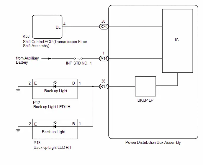
CAUTION / NOTICE / HINT
NOTICE:
- Inspect the fuses for circuits related to this system before performing the following procedure.
PROCEDURE
| 1. | READ VALUE USING GTS |
(a) Turn the ignition switch to ON.
(b) Move the shift lever to R.
(c) Read the Data List according to the display on the GTS.
Body Electrical > Power Distribution Box > Data List| Tester Display | Measurement Item | Normal Condition | Reference Value | Diagnostic Note |
|---|---|---|---|---|
| Back-up Light Fuse Shut Off Status | Back-up light fuse shut off status | OFF or ON | OFF: Fuse has no shut off history ON: Fuse has shut off history | - |
| Tester Display |
|---|
| Back-up Light Fuse Shut Off Status |
OK:
The Data List value displays "OFF".
| NG |

| GO TO STEP 7 |
|

| 2. | READ VALUE USING GTS |
(a) Read the Data List according to the display on the GTS.
Body Electrical > Power Distribution Box > Data List| Tester Display | Measurement Item | Normal Condition | Reference Value | Diagnostic Note |
|---|---|---|---|---|
| Back-up Light Input Signal | Back-up light input | OFF or ON | OFF: Shift lever in any position other than R ON: Shift lever in R | - |
| Tester Display |
|---|
| Back-up Light Input Signal |
OK:
Display changes according to shift lever operation.
| NG |

| GO TO STEP 5 |
|

| 3. | CHECK HARNESS AND CONNECTOR (POWER SOURCE - POWER DISTRIBUTION BOX ASSEMBLY) |
(a) Disconnect the A14 power distribution box assembly connector.
(b) Measure the voltage according to the value(s) in the table below.
Standard Voltage:
 Click Location & Routing(A14) Click Connector(A14)
 | Tester Connection | Condition | Specified Condition |
|---|---|---|
| A14-1 - Body ground | Ignition switch off | 11 to 14 V |
| NG |

| REPAIR OR REPLACE HARNESS OR CONNECTOR |
|

| 4. | CHECK HARNESS AND CONNECTOR (BACK-UP LIGHT LED - POWER DISTRIBUTION BOX ASSEMBLY) |
(a) Disconnect the P12 back-up light LED LH connector.
(b) Disconnect the P13 back-up light LED RH connector.
(c) Disconnect the R17 power distribution box assembly connector.
(d) Measure the resistance according to the value(s) in the table below.
Standard Resistance:
 Click Location & Routing(P12,R17,P13) Click Connector(P12) Click Connector(R17) Click Connector(P13)
 | Tester Connection | Condition | Specified Condition |
|---|---|---|
| P12-1(B) - R17-38 | Always | Below 1 Ω |
| P13-1(B) - R17-38 | Always | Below 1 Ω |
| OK |

| REPLACE POWER DISTRIBUTION BOX ASSEMBLY
|


| NG |

| REPAIR OR REPLACE HARNESS OR CONNECTOR |
| 5. | CHECK HARNESS AND CONNECTOR (SHIFT CONTROL ECU (TRANSMISSION FLOOR SHIFT ASSEMBLY) - POWER DISTRIBUTION BOX ASSEMBLY) |
(a) Disconnect the K53 shift control ECU (transmission floor shift assembly) connector.
(b) Disconnect the K20 power distribution box assembly connector.
(c) Measure the resistance according to the value(s) in the table below.
Standard Resistance:
 Click Location & Routing(K53,K20) Click Connector(K53) Click Connector(K20)
 | Tester Connection | Condition | Specified Condition |
|---|---|---|
| K53-4(BL) - K20-30 | Always | Below 1 Ω |
| K53-4 (BL) or K20-30 - Body ground | Always | 10 kΩ or higher |
| NG |

| REPAIR OR REPLACE HARNESS OR CONNECTOR |
|

| 6. | CHECK SHIFT CONTROL ECU (TRANSMISSION FLOOR SHIFT ASSEMBLY) (OUTPUT VOLTAGE) |
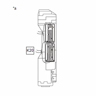
| *a | Component with harness connected (Power Distribution Box Assembly) |
(a) Connect the K53 shift control ECU (transmission floor shift assembly) connector.
(b) Connect the K20 power distribution box assembly connector.
(c) Measure the voltage according to the value(s) in the table below.
Standard Voltage:
 Click Location & Routing(K20) Click Connector(K20)
 | Tester Connection | Condition | Specified Condition |
|---|---|---|
| K20-30 - Body ground | Ignition switch ON, reverse (R) not selected | Below 1 V |
| K20-30 - Body ground | Ignition switch ON, reverse (R) selected | 11 to 14 V |
| OK |

| REPLACE POWER DISTRIBUTION BOX ASSEMBLY
|


| NG |

| REPLACE SHIFT CONTROL ECU (TRANSMISSION FLOOR SHIFT ASSEMBLY) |
| 7. | CHECK BACK-UP LIGHT LED LH |
(a) Disconnect the P12 back-up light LED LH connector.
(b) Turn the ignition switch to ON.
(c) Move the shift lever to R.
(d) Read the Data List according to the display on the GTS.
Body Electrical > Power Distribution Box > Data List| Tester Display | Measurement Item | Normal Condition | Reference Value | Diagnostic Note |
|---|---|---|---|---|
| Back-up Light Fuse Shut Off Status | Back-up light fuse shut off status | OFF or ON | OFF: Fuse has no shut off history ON: Fuse has shut off history | - |
| Tester Display |
|---|
| Back-up Light Fuse Shut Off Status |
OK:
The Data List value displays "OFF".
| OK |

| REPLACE BACK-UP LIGHT LED LH |
|

| 8. | CHECK BACK-UP LIGHT LED RH |
(a) Disconnect the P13 back-up light LED RH connector.
(b) Turn the ignition switch to ON.
(c) Move the shift lever to R.
(d) Read the Data List according to the display on the GTS.
Body Electrical > Power Distribution Box > Data List| Tester Display | Measurement Item | Normal Condition | Reference Value | Diagnostic Note |
|---|---|---|---|---|
| Back-up Light Fuse Shut Off Status | Back-up light fuse shut off status | OFF or ON | OFF: Fuse has no shut off history ON: Fuse has shut off history | - |
| Tester Display |
|---|
| Back-up Light Fuse Shut Off Status |
OK:
The Data List value displays "OFF".
| OK |

| REPLACE BACK-UP LIGHT LED RH |
| NG |

| REPAIR OR REPLACE HARNESS OR CONNECTOR |
Charge Lid Illumination Malfunction
DESCRIPTION
The plugin charge control ECU assembly turns the spot light assembly on when the charging port lid is open and turns it off when the charging port lid is closed. The spot light assembly will turn off when the charger cable (electric vehicle charger cable assembly) is connected and turn on when the charger cable (electric Toyota Prius vehicle charger cable assembly) is disconnected.
WIRING DIAGRAM
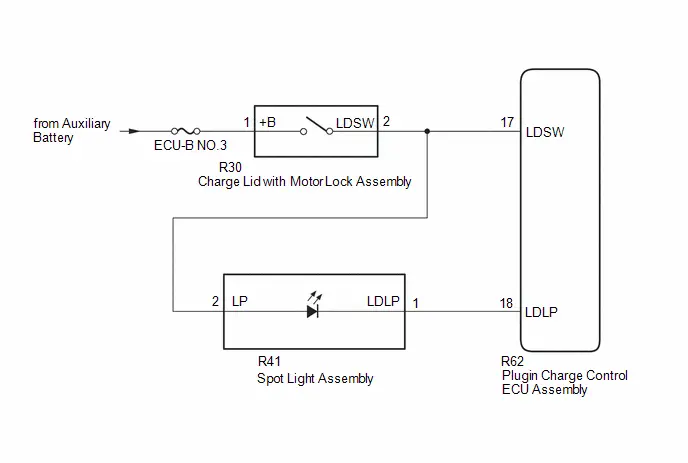
CAUTION / NOTICE / HINT
CAUTION:
-
Before the following operations are conducted, take precautions to prevent electric shock by turning the ignition switch off, wearing insulated gloves, and removing the service plug grip from HV battery.
-
To prevent electric shock, make sure to remove the service plug grip to cut off the high voltage circuit before servicing the Toyota Prius vehicle.
-
After removing the service plug grip, put it in your pocket to prevent other technicians from accidentally reconnecting it while you are working on the high-voltage system.
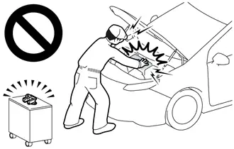
-
After removing the service plug grip, wait for at least 10 minutes before touching any of the high-voltage connectors or terminals.
Waiting for at least 10 minutes is required to discharge the high-voltage capacitor inside the inverter with converter assembly.
Click here

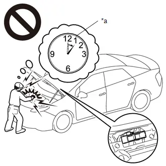
*a
Without waiting for 10 minutes
NOTICE:
Inspect the fuses for circuits related to this system before performing the following procedure.
PROCEDURE
| 1. | CHECK FOR DTC |
(a) Enter the following menus: System Select / Health Check.
(b) Check for DTCs.
| Result | Proceed to |
|---|---|
| DTCs are not output | A |
| DTCs are output | B |
(c) Turn the ignition switch off.
| B |

| GO TO OTHER DTC CHART |
|

| 2. | INSPECT PLUGIN CHARGE CONTROL ECU ASSEMBLY (CHARGE LID WITH MOTOR LOCK ASSEMBLY STATUS) |
CAUTION:
Be sure to wear insulated gloves.
(a) Check that the service plug grip is not installed.
NOTICE:
After removing the service plug grip, do not turn the ignition switch to on (READY), unless instructed by the repair manual because this may cause a malfunction.
(b) Connect the cable to the negative (-) auxiliary battery terminal.
(c) Turn the ignition switch to ON.
(d) Measure the voltage according to the value(s) in the table below.
HINT:
- When the charging port lid is opened with all of the doors unlocked, the charging port lid is judged to be open.
- When the charging port lid is closed with all of the doors locked, the charging port lid is judged to be closed.
Standard Voltage:
 Click Location & Routing(R62) Click Connector(R62)
 | Tester Connection | Condition | Specified Condition |
|---|---|---|
| R62-17 (LDSW) - Body ground | Ignition switch on, charging port lid open, all doors unlocked | 11 to 14 V |
| R62-17 (LDSW) - Body ground | Ignition switch on, charging port lid closed, all doors locked | 0 to 1.5 V |
(e) Turn the ignition switch off.
| NG |

| GO TO STEP 11 |
|

| 3. | INSPECT PLUGIN CHARGE CONTROL ECU ASSEMBLY (LDSW TERMINAL VOLTAGE) |
(a) Disconnect the R62 plugin charge control ECU assembly connector.
(b) Turn the ignition switch to ON.
(c) Measure the voltage according to the value(s) in the table below.
Standard Voltage:
 Click Location & Routing(R62) Click Connector(R62)
 | Tester Connection | Condition | Specified Condition |
|---|---|---|
| R62-17 (LDSW) - Body ground | Ignition switch on, charging port lid open, all doors unlocked | 11 to 14 V |
(d) Turn the ignition switch off.
| NG |

| GO TO STEP 11 |
|

| 4. | READ VALUE USING GTS |
CAUTION:
Be sure to wear insulated gloves.
(a) Check that the service plug grip is not installed.
NOTICE:
After removing the service plug grip, do not turn the ignition switch to on (READY), unless instructed by the repair manual because this may cause a malfunction.
(b) Connect the R62 plugin charge control ECU assembly connector.
(c) Measure the voltage according to the value(s) in the table below.
HINT:
- When the charging port lid is opened with all of the doors unlocked, the charging port lid is judged to be open.
- When the charging port lid is closed with all of the doors locked, the charging port lid is judged to be closed.
Standard Voltage:
 Click Location & Routing(R62) Click Connector(R62)
 | Tester Connection | Condition | Specified Condition |
|---|---|---|
| R62-17 (LDSW) - Body ground | Ignition switch on, charging port lid open, all doors unlocked | 11 to 14 V |
| R62-17 (LDSW) - Body ground | Ignition switch on, charging port lid closed, all doors locked | 0 to 1.5 V |
(d) Read the Data List according to the display on the GTS.
Powertrain > Plug-in Control > Data List| Tester Display | Measurement Item | Range | Normal Condition | Diagnostic Note |
|---|---|---|---|---|
| Charging Lid Switch Status | Charge lid with motor lock assembly status | OFF or ON | OFF: Charging port lid closed ON: Charging port lid open | - |
| Tester Display |
|---|
| Charging Lid Switch Status |
HINT:
- The Data List allows the state of the inspection terminal to be read.
- As the value of the Data List may vary when taking measurements due to factors such as the environment, Toyota Prius vehicle age, etc., the result should be used as a reference only.
(e) Turn the ignition switch off.
| Result | Proceed to |
|---|---|
| The Data List item and voltage change accordingly | A |
| The Data List item and voltage do not change accordingly | B |
| B |

| REPLACE PLUGIN CHARGE CONTROL ECU ASSEMBLY |
|

| 5. | INSPECT PLUGIN CHARGE CONTROL ECU ASSEMBLY (SPOT LIGHT ASSEMBLY STATUS) |
CAUTION:
Be sure to wear insulated gloves.
(a) Check that the service plug grip is not installed.
NOTICE:
After removing the service plug grip, do not turn the ignition switch to on (READY), unless instructed by the repair manual because this may cause a malfunction.
(b) Turn the ignition switch to ON.
(c) Measure the voltage according to the value(s) in the table below.
HINT:
- When the charging port lid is opened with all of the doors unlocked, the charging port lid is judged to be open.
- When the charging port lid is closed with all of the doors locked, the charging port lid is judged to be closed.
Standard Voltage:
 Click Location & Routing(R62) Click Connector(R62)
 | Tester Connection | Condition | Specified Condition |
|---|---|---|
| R62-18 (LDLP) - Body ground | Ignition switch on, charging port lid closed, all doors locked | 0 to 1.5 V |
(d) Turn the ignition switch off.
| NG |

| GO TO STEP 8 |
|

| 6. | INSPECT PLUGIN CHARGE CONTROL ECU ASSEMBLY (LDLP TERMINAL VOLTAGE) |
(a) Disconnect the R62 plugin charge control ECU assembly connector.
(b) Turn the ignition switch to ON.
(c) Measure the voltage according to the value(s) in the table below.
Standard Voltage:
 Click Location & Routing(R62) Click Connector(R62)
 | Tester Connection | Condition | Specified Condition |
|---|---|---|
| R62-18 (LDLP) - Body ground | Ignition switch on, charging port lid open, all doors unlocked | 5 to 14 V |
(d) Turn the ignition switch off.
| NG |

| GO TO STEP 8 |
|

| 7. | READ VALUE USING GTS |
CAUTION:
Be sure to wear insulated gloves.
(a) Check that the service plug grip is not installed.
NOTICE:
After removing the service plug grip, do not turn the ignition switch to on (READY), unless instructed by the repair manual because this may cause a malfunction.
(b) Connect the R62 plugin charge control ECU assembly connector.
(c) Measure the voltage according to the value(s) in the table below.
HINT:
- The spot light assembly illuminates when the charging port lid is opened with all of the doors unlocked.
-
When any of the following conditions is met, the spot light assembly turns off.
- The charging port lid is open and the spot light assembly is illuminated for 20 minutes or more.
- The charge plug is connected when the charging port lid open. (The spot light assembly turns off 7.5 seconds after the charge plug is connected.)
- The charging port lid is closed with all of the doors locked.
Standard Voltage:
 Click Location & Routing(R62) Click Connector(R62)
 | Tester Connection | Condition | Specified Condition |
|---|---|---|
| R62-18 (LDLP) - Body ground | Ignition switch on, charging port lid closed, spot light assembly not illuminated | 0 to 1.5 V |
| R62-18 (LDLP) - Body ground | Ignition switch on, charging port lid open, spot light assembly not illuminated | 5 to 14 V |
| R62-18 (LDLP) - Body ground | Ignition switch on, charging port lid open, spot light assembly illuminated | 0 to 5 V |
(d) Enter the following menus: Powertrain / Plug-in Control / Data List.
(e) Read the Data List according to the display on the GTS.
Powertrain > Plug-in Control > Data List| Tester Display | Measurement Item | Range | Normal Condition | Diagnostic Note |
|---|---|---|---|---|
| Charging Lid Lamp Status | Spot light assembly status | OFF, Fade Out or ON | OFF: Spot light assembly off Fade Out: Spot light assembly fading out ON: Spot light assembly on | - |
| Tester Display |
|---|
| Charging Lid Lamp Status |
HINT:
- The Data List allows the state of the inspection terminal to be read.
- As the value of the Data List may vary when taking measurements due to factors such as the environment, Toyota Prius vehicle age, etc., the result should be used as a reference only.
| Result | Proceed to |
|---|---|
| A |
| Other than above | B |
| A |

| GO TO CAUSE ANALYSIS (USER RELATED CAUSE) (a) Perform cause analysis as specified in the following table.
(b) Take appropriate action in accordance with the result of the cause analysis. |
| B |

| REPLACE PLUGIN CHARGE CONTROL ECU ASSEMBLY |
| 8. | INSPECT SPOT LIGHT ASSEMBLY |
Click here

| NG |

| REPLACE SPOT LIGHT ASSEMBLY |
|

| 9. | CHECK HARNESS AND CONNECTOR (CHARGE LID WITH MOTOR LOCK ASSEMBLY - SPOT LIGHT ASSEMBLY) |
(a) Disconnect the R30 charge lid with motor lock assembly connector.
(b) Measure the resistance according to the value(s) in the table below.
Standard Resistance:
 Click Location & Routing(R30,R41) Click Connector(R30) Click Connector(R41)
 | Tester Connection | Condition | Specified Condition |
|---|---|---|
| R30-2 (LDSW) - R41-2 (LP) | Always | Below 1 Ω |
| R30-2 (LDSW) or R41-2 (LP) - Body ground | Always | 10 kΩ or higher |
| NG |

| REPAIR OR REPLACE HARNESS OR CONNECTOR |
|

| 10. | CHECK HARNESS AND CONNECTOR (SPOT LIGHT ASSEMBLY - PLUGIN CHARGE CONTROL ECU ASSEMBLY) |
(a) Disconnect the R62 plugin charge control ECU assembly connector.
(b) Measure the resistance according to the value(s) in the table below.
Standard Resistance:
 Click Location & Routing(R41,R62) Click Connector(R41) Click Connector(R62)
 | Tester Connection | Condition | Specified Condition |
|---|---|---|
| R41-1 (LDLP) - R62-18 (LDLP) | Always | Below 1 Ω |
| R41-1 (LDLP) or R62-18 (LDLP) - Body ground | Always | 10 kΩ or higher |
| OK |

| REPLACE PLUGIN CHARGE CONTROL ECU ASSEMBLY |
| NG |

| REPAIR OR REPLACE HARNESS OR CONNECTOR |
| 11. | INSPECT CHARGE LID WITH MOTOR LOCK ASSEMBLY |
Click here

| NG |

| REPLACE CHARGE LID WITH MOTOR LOCK ASSEMBLY |
|

| 12. | CHECK HARNESS AND CONNECTOR (AUXILIARY BATTERY - CHARGE LID WITH MOTOR LOCK ASSEMBLY) |
(a) Measure the voltage according to the value(s) in the table below.
Standard Voltage:
 Click Location & Routing(R30) Click Connector(R30)
 | Tester Connection | Condition | Specified Condition |
|---|---|---|
| R30-1 ( B) - Body ground | Ignition switch off | 11 to 14 V |
| NG |

| REPAIR OR REPLACE HARNESS OR CONNECTOR |
|

| 13. | CHECK HARNESS AND CONNECTOR (CHARGE LID WITH MOTOR LOCK ASSEMBLY - PLUGIN CHARGE CONTROL ECU ASSEMBLY) |
(a) Disconnect the R62 plugin charge control ECU assembly connector.
(b) Measure the resistance according to the value(s) in the table below.
Standard Resistance:
 Click Location & Routing(R30,R62) Click Connector(R30) Click Connector(R62)
 | Tester Connection | Condition | Specified Condition |
|---|---|---|
| R30-2 (LDSW) - R62-17 (LDSW) | Always | Below 1 Ω |
| R30-2 (LDSW) or R62-17 (LDSW) - Body ground | Always | 10 kΩ or higher |
| OK |

| REPLACE PLUGIN CHARGE CONTROL ECU ASSEMBLY |
| NG |

| REPAIR OR REPLACE HARNESS OR CONNECTOR |
LO-beam Headlight does not Illuminate
DESCRIPTION
The main body ECU (multiplex network body ECU) controls the low beam headlights.
WIRING DIAGRAM

HEADLIGHT ASSEMBLY CIRCUIT (w/o Front Side Marker Light)
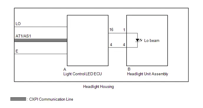
CAUTION / NOTICE / HINT
NOTICE:
- Inspect the fuses for circuits related to this system before performing the following procedure.
-
Before replacing the main body ECU (multiplex network body ECU), refer to Registration.
Click here

-
First perform the communication function inspections in How to Proceed with Troubleshooting to confirm that there are no CXPI communication malfunctions before troubleshooting this symptom.
Click here


PROCEDURE
| 1. | CONFIRM MODEL |
(a) Choose the model to be inspected.
| Result | Proceed to |
|---|---|
| w/ Front Side Marker Light | A |
| w/o Front Side Marker Light | B |
| B |

| GO TO STEP 3 |
|

| 2. | PERFORM ACTIVE TEST USING GTS |
(a) Perform the Active Test according to the display on the GTS.
Body Electrical > Main Body > Active Test| Tester Display | Measurement Item | Control Range | Diagnostic Note |
|---|---|---|---|
| Headlight Relay / Light Power Supply Relay | Low beam headlights | OFF or ON | - |
| Tester Display |
|---|
| Headlight Relay / Light Power Supply Relay |
OK:
Low beam headlights illuminate.
| Result | Proceed to |
|---|---|
| OK | A |
| NG (LH side low beam headlight does not illuminate) | B |
| NG (RH side low beam headlight does not illuminate) | C |
| A |

| PROCEED TO NEXT SUSPECTED AREA SHOWN IN PROBLEM SYMPTOMS TABLE
|


| B |

| REPLACE HEADLIGHT HOUSING SUB-ASSEMBLY LH |
| C |

| REPLACE HEADLIGHT HOUSING SUB-ASSEMBLY RH |
| 3. | PERFORM ACTIVE TEST USING GTS |
(a) Perform the Active Test according to the display on the GTS.
Body Electrical > Main Body > Active Test| Tester Display | Measurement Item | Control Range | Diagnostic Note |
|---|---|---|---|
| Headlight Relay / Light Power Supply Relay | Low beam headlights | OFF or ON | - |
| Tester Display |
|---|
| Headlight Relay / Light Power Supply Relay |
OK:
Low beam headlights illuminate.
| Result | Proceed to |
|---|---|
| OK | A |
| NG (LH side low beam headlight does not illuminate) | B |
| NG (RH side low beam headlight does not illuminate) | C |
| A |

| PROCEED TO NEXT SUSPECTED AREA SHOWN IN PROBLEM SYMPTOMS TABLE
|


| C |

| GO TO STEP 6 |
|

| 4. | INSPECT LIGHT CONTROL LED ECU LH |
(a) Remove the headlight housing sub-assembly LH.
Click here


| *a | Component with harness connected (Light Control LED ECU LH) |
(b) Measure the voltage according to the value(s) in the table below.
Standard Voltage:
| Tester Connection | Condition | Specified Condition |
|---|---|---|
| A-16 - A-4 | Light control switch in HEAD position | 10 to 16 V |
| NG |

| REPLACE LIGHT CONTROL LED ECU LH |
|

| 5. | INSPECT HEADLIGHT HOUSING LH |
(a) Remove the headlight housing sub-assembly LH.
Click here

(b) Disconnect the light control LED ECU LH connector.
(c) Disconnect the headlight unit assembly LH connector.
(d) Measure the resistance according to the value(s) in the table below.

| *a | Component without harness connected (to Light Control LED ECU LH) | *b | Component without harness connected (to Headlight Unit assembly LH) |
Standard Resistance:
| Tester Connection | Condition | Specified Condition |
|---|---|---|
| A-16 - B-1 | Always | Below 1 Ω |
| A-4 - B-4 | Always | Below 1 Ω |
| OK |

| REPLACE HEADLIGHT UNIT ASSEMBLY LH |
| NG |

| REPLACE HEADLIGHT HOUSING LH |
| 6. | INSPECT LIGHT CONTROL LED ECU RH |
(a) Remove the headlight housing sub-assembly RH.
Click here


| *a | Component with harness connected (Light Control LED ECU RH) |
(b) Measure the voltage according to the value(s) in the table below.
Standard Voltage:
| Tester Connection | Condition | Specified Condition |
|---|---|---|
| A-16 - A-4 | Light control switch in HEAD position | 10 to 16 V |
| NG |

| REPLACE LIGHT CONTROL LED ECU RH |
|

| 7. | INSPECT HEADLIGHT HOUSING RH |
(a) Remove the headlight housing sub-assembly RH.
Click here

(b) Disconnect the light control LED ECU RH connector.
(c) Disconnect the headlight unit assembly RH connector.
(d) Measure the resistance according to the value(s) in the table below.

| *a | Component without harness connected (to Light Control LED ECU RH) | *b | Component without harness connected (to Headlight Unit assembly RH) |
Standard Resistance:
| Tester Connection | Condition | Specified Condition |
|---|---|---|
| A-16 - B-1 | Always | Below 1 Ω |
| A-4 - B-4 | Always | Below 1 Ω |
| OK |

| REPLACE HEADLIGHT UNIT ASSEMBLY RH |
| NG |

| REPLACE HEADLIGHT HOUSING RH |
Taillight Relay Circuit
DESCRIPTION
The main body ECU (multiplex network body ECU) controls the operation of the TAIL relay.
WIRING DIAGRAM
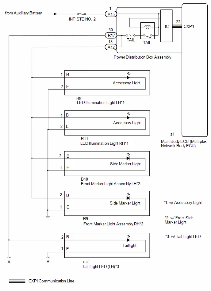
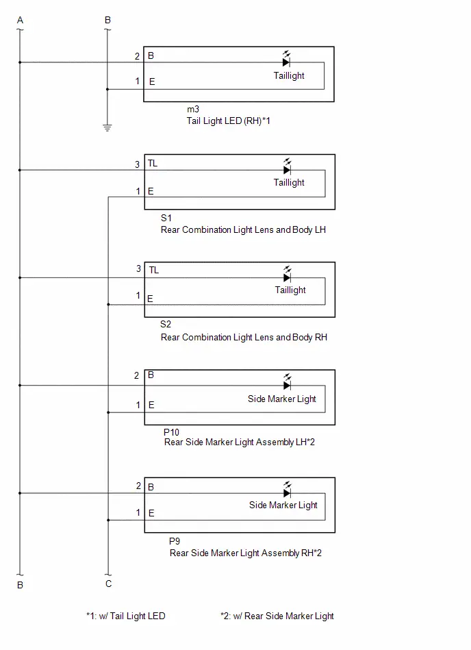
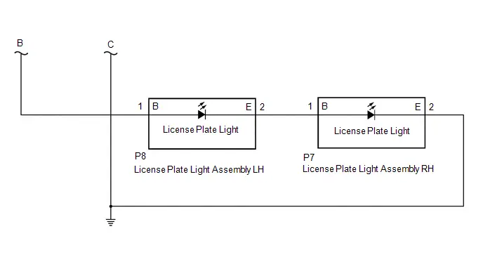
CAUTION / NOTICE / HINT
NOTICE:
- Inspect the fuses for circuits related to this system before performing the following procedure.
-
Before replacing the main body ECU (multiplex network body ECU), refer to Registration.
Click here

-
First perform the communication function inspections in How to Proceed with Troubleshooting to confirm that there are no CXPI communication malfunctions before troubleshooting this symptom.
Click here


PROCEDURE
| 1. | PERFORM ACTIVE TEST USING GTS |
(a) Read the Data List according to the display on the GTS.
Body Electrical > Main Body > Active Test| Tester Display | Measurement Item | Control Range | Diagnostic Note |
|---|---|---|---|
| Taillight / Clearance Light | Taillights/parking lights | OFF or ON | - |
| Tester Display |
|---|
| Taillight / Clearance Light |
OK:
taillights illuminate.
| OK |

| PROCEED TO NEXT SUSPECTED AREA SHOWN IN PROBLEM SYMPTOMS TABLE
|


|

| 2. | CHECK HARNESS AND CONNECTOR (POWER SOURCE - POWER DISTRIBUTION BOX ASSEMBLY) |
(a) Disconnect the A15 power distribution box assembly connector.
(b) Measure the voltage according to the value(s) in the table below.
Standard Voltage:
 Click Location & Routing(A15) Click Connector(A15)
 | Tester Connection | Condition | Specified Condition |
|---|---|---|
| A15-1 - Body ground | Ignition switch off | 11 to 14 V |
| NG |

| REPAIR OR REPLACE HARNESS OR CONNECTOR |
|

| 3. | CHECK HARNESS AND CONNECTOR (TAILLIGHT CIRCUIT) |
(a) Disconnect the B8 LED illumination light LH connector. (w/ Accessory Light)
(b) Disconnect the B11 LED illumination light RH connector. (w/ Accessory Light)
(c) Disconnect the B10 front marker light assembly LH connector. (w/ Front Side Marker Light)
(d) Disconnect the B9 front marker light assembly RH connector. (w/ Front Side Marker Light)
(e) Disconnect the m2 tail light LED (LH) connector. (w/ Tail Light LED)
(f) Disconnect the m3 tail light LED (RH) connector. (w/ Tail Light LED)
(g) Disconnect the S1 rear combination light lens and body LH connector.
(h) Disconnect the S2 rear combination light lens and body RH connector.
(i) Disconnect the P10 rear side marker light assembly LH connector. (w/ Rear Side Marker Light)
(j) Disconnect the P9 rear side marker light assembly RH connector. (w/ Rear Side Marker Light)
(k) Disconnect the P8 license plate light assembly LH connector.
(l) Measure the resistance according to the value(s) in the table below.
Standard Resistance:
 Click Location & Routing(S1,R17,B8,B10,A12) Click Connector(S1) Click Connector(R17) Click Connector(B8) Click Connector(B10) Click Connector(A12)
 | Tester Connection | Condition | Specified Condition |
|---|---|---|
| S1-3 (TL) - R17-30 | Always | Below 1 Ω |
| B8-1 (B)*1 or B10-2 (B)*2 - A12-18*1, *2 | Always | Below 1 Ω |
| S1-3 (TL) or R17-30 - Body ground | Always | 10 kΩ or higher |
| B8-1 (B)*1, B10-2 (B)*2 or A12-18 - Body ground*1, *2 | Always | 10 kΩ or higher |
- *1: w/ Accessory Light
- *2: w/ Rear Side Marker Light
| NG |

| REPAIR OR REPLACE HARNESS OR CONNECTOR |
|

| 4. | CHECK POWER DISTRIBUTION BOX ASSEMBLY |
(a) Connect the A15 power distribution box assembly connector.
(b) Connect the R17 power distribution box assembly connector.
(c) Connect the A12 power distribution box assembly connector.*1,*2
- *1: w/ Accessory Light
- *2: w/ Front Side Marker Light
(d) Turn the light control switch to the tail position.
(e) Measure the voltage according to the value(s) in the table below.
Standard Voltage:
 Click Location & Routing(R17) Click Connector(R17)
 | Tester Connection | Condition | Specified Condition |
|---|---|---|
| R17-30 - Body ground | Ignition switch off | 11 to 14 V |
| Result | Proceed to |
|---|---|
| OK (w/ Front Side Marker Light) | A |
| OK (w/o Front Side Marker Light) | B |
| NG | C |
| B |

| GO TO STEP 9 |
| C |

| REPLACE POWER DISTRIBUTION BOX ASSEMBLY
|


|

| 5. | CHECK FRONT MARKER LIGHT ASSEMBLY LH |
(a) Connect the B10 front marker light assembly LH connector.
(b) Turn the light control switch to the tail position.
(c) Measure the voltage according to the value(s) in the table below.
Standard Voltage:
 Click Location & Routing(S1) Click Connector(S1)
 | Tester Connection | Condition | Specified Condition |
|---|---|---|
| S1-3 (TL) - Body ground | Ignition switch off | 11 to 14 V |
| NG |

| REPLACE FRONT MARKER LIGHT ASSEMBLY LH |
|

| 6. | CHECK FRONT MARKER LIGHT ASSEMBLY RH |
(a) Connect the B9 front marker light assembly RH connector.
(b) Turn the light control switch to the tail position.
(c) Measure the voltage according to the value(s) in the table below.
Standard Voltage:
 Click Location & Routing(S1) Click Connector(S1)
 | Tester Connection | Condition | Specified Condition |
|---|---|---|
| S1-3 (TL) - Body ground | Ignition switch off | 11 to 14 V |
| Result | Proceed to |
|---|---|
| OK (w/ Accessory Light) | A |
| OK (w/o Accessory Light) | B |
| NG | C |
| B |

| GO TO STEP 9 |
| C |

| REPLACE FRONT MARKER LIGHT ASSEMBLY RH |
|

| 7. | CHECK LED ILLUMINATION LIGHT LH |
(a) Connect the B8 LED illumination light LH connector.
(b) Turn the light control switch to the tail position.
(c) Measure the voltage according to the value(s) in the table below.
Standard Voltage:
 Click Location & Routing(S1) Click Connector(S1)
 | Tester Connection | Condition | Specified Condition |
|---|---|---|
| S1-3 (TL) - Body ground | Ignition switch off | 11 to 14 V |
| NG |

| REPLACE LED ILLUMINATION LIGHT LH |
|

| 8. | CHECK LED ILLUMINATION LIGHT RH |
(a) Connect the B11 LED illumination light RH connector.
(b) Turn the light control switch to the tail position.
(c) Measure the voltage according to the value(s) in the table below.
Standard Voltage:
 Click Location & Routing(S1) Click Connector(S1)
 | Tester Connection | Condition | Specified Condition |
|---|---|---|
| S1-3 (TL) - Body ground | Ignition switch off | 11 to 14 V |
| OK |

| GO TO STEP 9 |
| NG |

| REPLACE LED ILLUMINATION LIGHT RH |
| 9. | CHECK REAR COMBINATION LIGHT LENS AND BODY LH |
(a) Connect the S1 rear combination light lens and body LH connector.
(b) Turn the light control switch to the tail position.
(c) Measure the voltage according to the value(s) in the table below.
Standard Voltage:
 Click Location & Routing(P8) Click Connector(P8)
 | Tester Connection | Condition | Specified Condition |
|---|---|---|
| P8-1 (B) - Body ground | Ignition switch off | 11 to 14 V |
| NG |

| REPLACE REAR COMBINATION LIGHT LENS AND BODY LH |
|

| 10. | CHECK REAR COMBINATION LIGHT LENS AND BODY RH |
(a) Connect the S2 rear combination light lens and body RH connector.
(b) Turn the light control switch to the tail position.
(c) Measure the voltage according to the value(s) in the table below.
Standard Voltage:
 Click Location & Routing(P8) Click Connector(P8)
 | Tester Connection | Condition | Specified Condition |
|---|---|---|
| P8-1 (B) - Body ground | Ignition switch off | 11 to 14 V |
| Result | Proceed to |
|---|---|
| OK (w/ Rear Side Marker Light) | A |
| OK (w/o Rear Side Marker Light) | B |
| NG | C |
| B |

| REPLACE LICENSE PLATE LIGHT ASSEMBLY |
| C |

| REPLACE REAR COMBINATION LIGHT LENS AND BODY RH |
|

| 11. | CHECK REAR SIDE MARKER LIGHT ASSEMBLY LH |
(a) Connect the P10 rear side marker light assembly LH connector.
(b) Turn the light control switch to the tail position.
(c) Measure the voltage according to the value(s) in the table below.
Standard Voltage:
 Click Location & Routing(P8) Click Connector(P8)
 | Tester Connection | Condition | Specified Condition |
|---|---|---|
| P8-1 (B) - Body ground | Ignition switch off | 11 to 14 V |
| NG |

| REPLACE REAR SIDE MARKER LIGHT ASSEMBLY LH |
|

| 12. | CHECK REAR SIDE MARKER LIGHT ASSEMBLY RH |
(a) Connect the P9 rear side marker light assembly RH connector.
(b) Turn the light control switch to the tail position.
(c) Measure the voltage according to the value(s) in the table below.
Standard Voltage:
 Click Location & Routing(P8) Click Connector(P8)
 | Tester Connection | Condition | Specified Condition |
|---|---|---|
| P8-1 (B) - Body ground | Ignition switch off | 11 to 14 V |
| Result | Proceed to |
|---|---|
| OK (w/ Tail Light LED) | A |
| OK (w/o Tail Light LED) | B |
| NG | C |
| B |

| REPLACE LICENSE PLATE LIGHT ASSEMBLY |
| C |

| REPLACE REAR SIDE MARKER LIGHT ASSEMBLY RH |
|

| 13. | CHECK TAIL LIGHT LED (LH) |
(a) Connect the m2 tail light LED (LH) connector.
(b) Turn the light control switch to the tail position.
(c) Measure the voltage according to the value(s) in the table below.
Standard Voltage:
 Click Location & Routing(P8) Click Connector(P8)
 | Tester Connection | Condition | Specified Condition |
|---|---|---|
| P8-1 (B) - Body ground | Ignition switch off | 11 to 14 V |
| NG |

| REPLACE TAIL LIGHT LED (LH) |
|

| 14. | CHECK TAIL LIGHT LED (RH) |
(a) Connect the m3 tail light LED (RH) connector.
(b) Turn the light control switch to the tail position.
(c) Measure the voltage according to the value(s) in the table below.
Standard Voltage:
 Click Location & Routing(P8) Click Connector(P8)
 | Tester Connection | Condition | Specified Condition |
|---|---|---|
| P8-1 (B) - Body ground | Ignition switch off | 11 to 14 V |
| OK |

| REPLACE LICENSE PLATE LIGHT ASSEMBLY |
| NG |

| REPLACE TAIL LIGHT LED (RH) |
High Beam Headlight Circuit
DESCRIPTION
The main body ECU (multiplex network body ECU) controls the high beam headlights.
WIRING DIAGRAM

HEADLIGHT ASSEMBLY CIRCUIT (w/o Front Side Marker Light)
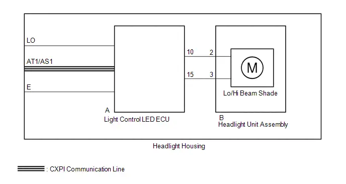
CAUTION / NOTICE / HINT
NOTICE:
- Inspect the fuses for circuits related to this system before performing the following procedure.
-
Before replacing the main body ECU (multiplex network body ECU), refer to Registration.
Click here

-
First perform the communication function inspections in How to Proceed with Troubleshooting to confirm that there are no CXPI communication malfunctions before troubleshooting this symptom.
Click here


PROCEDURE
| 1. | CONFIRM MODEL |
(a) Choose the model to be inspected.
| Result | Proceed to |
|---|---|
| w/ Front Side Marker Light | A |
| w/o Front Side Marker Light | B |
| B |

| GO TO STEP 3 |
|

| 2. | PERFORM ACTIVE TEST USING GTS |
(a) Perform the Active Test according to the display on the GTS.
Body Electrical > Main Body > Active Test| Tester Display | Measurement Item | Control Range | Diagnostic Note |
|---|---|---|---|
| High Beam Headlight | High beam headlights | OFF or ON | - |
| Tester Display |
|---|
| High Beam Headlight |
OK:
High beam headlights illuminate.
| Result | Proceed to |
|---|---|
| OK | A |
| NG (LH side high beam headlight does not illuminate) | B |
| NG (RH side high beam headlight does not illuminate) | C |
| A |

| PROCEED TO NEXT SUSPECTED AREA SHOWN IN PROBLEM SYMPTOMS TABLE
|


| B |

| REPLACE HEADLIGHT HOUSING SUB-ASSEMBLY LH |
| C |

| REPLACE HEADLIGHT HOUSING SUB-ASSEMBLY RH |
| 3. | PERFORM ACTIVE TEST USING GTS |
(a) Perform the Active Test according to the display on the GTS.
Body Electrical > Main Body > Active Test| Tester Display | Measurement Item | Control Range | Diagnostic Note |
|---|---|---|---|
| High Beam Headlight | High beam headlights | OFF or ON | - |
| Tester Display |
|---|
| High Beam Headlight |
OK:
High beam headlights illuminate.
| Result | Proceed to |
|---|---|
| OK | A |
| NG (LH side high beam headlight does not illuminate) | B |
| NG (RH side high beam headlight does not illuminate) | C |
| A |

| PROCEED TO NEXT SUSPECTED AREA SHOWN IN PROBLEM SYMPTOMS TABLE
|


| C |

| GO TO STEP 6 |
|

| 4. | INSPECT LIGHT CONTROL LED ECU LH |
(a) Remove the headlight housing sub-assembly LH.
Click here


| *a | Component with harness connected (Light Control LED ECU LH) |
(b) Measure the voltage according to the value(s) in the table below.
Standard Voltage:
| Tester Connection | Condition | Specified Condition |
|---|---|---|
| A-10 - A-15 | Light control switch in HEAD position | 10 to 16 V |
| NG |

| REPLACE LIGHT CONTROL LED ECU LH |
|

| 5. | INSPECT HEADLIGHT HOUSING LH |
(a) Remove the headlight housing sub-assembly LH.
Click here

(b) Disconnect the light control LED ECU LH connector.
(c) Disconnect the headlight unit assembly LH connector.
(d) Measure the resistance according to the value(s) in the table below.
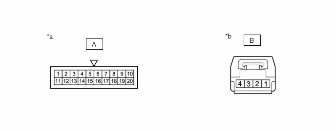
| *a | Component without harness connected (to Light Control LED ECU LH) | *b | Component without harness connected (to Headlight Unit assembly LH) |
Standard Resistance:
| Tester Connection | Condition | Specified Condition |
|---|---|---|
| A-10 - B-2 | Always | Below 1 Ω |
| A-15 - B-3 | Always | Below 1 Ω |
| OK |

| REPLACE HEADLIGHT UNIT ASSEMBLY LH |
| NG |

| REPLACE HEADLIGHT HOUSING LH |
| 6. | INSPECT LIGHT CONTROL LED ECU RH |
(a) Remove the headlight housing sub-assembly RH.
Click here


| *a | Component with harness connected (Light Control LED ECU LH) |
(b) Measure the voltage according to the value(s) in the table below.
Standard Voltage:
| Tester Connection | Condition | Specified Condition |
|---|---|---|
| A-10 - A-15 | Light control switch in HEAD position | 10 to 16 V |
| NG |

| REPLACE LIGHT CONTROL LED ECU RH |
|

| 7. | INSPECT HEADLIGHT HOUSING RH |
(a) Remove the headlight housing sub-assembly RH.
Click here

(b) Disconnect the light control LED ECU RH connector.
(c) Disconnect the headlight unit assembly RH connector.
(d) Measure the resistance according to the value(s) in the table below.

| *a | Component without harness connected (to Light Control LED ECU RH) | *b | Component without harness connected (to Headlight Unit assembly RH) |
Standard Resistance:
| Tester Connection | Condition | Specified Condition |
|---|---|---|
| A-10 - B-2 | Always | Below 1 Ω |
| A-15 - B-3 | Always | Below 1 Ω |
| OK |

| REPLACE HEADLIGHT UNIT ASSEMBLY RH |
| NG |

| REPLACE HEADLIGHT HOUSING RH |

Toyota Prius (XW60) 2023-2026 Service Manual
Lighting System
- Precaution
- Parts Location
- System Diagram
- How To Proceed With Troubleshooting
- Operation Check
- Customize Parameters
- Problem Symptoms Table
- Terminals Of Ecu
- Data List / Active Test
- Diagnostic Trouble Code Chart
- Light Sensor Circuit Malfunction (B124400)
- Headlight LH Circuit (B243900,B243A00)
- Lost Communication With ECM/PCM "A" Missing Message (U010087,...,U111787)
- Turn Signal Switch Circuit
- Headlight Dimmer Switch Circuit
- Parking Light/Daytime Running Light Circuit
- Hazard Warning Switch Circuit
- Back-up Light Circuit
- Charge Lid Illumination Malfunction
- LO-beam Headlight does not Illuminate
- Taillight Relay Circuit
- High Beam Headlight Circuit
Actual pages
Beginning midst our that fourth appear above of over, set our won’t beast god god dominion our winged fruit image
