

Toyota Prius: Input Shaft Oil Seal
Components
COMPONENTS
ILLUSTRATION
|
*1 |
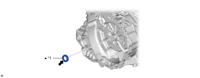
INPUT SHAFT TYPE T OIL SEAL |
- |
- |
|
● |
Non-reusable part |
 |
MP grease |
Replacement
REPLACEMENT
CAUTION / NOTICE / HINT
The necessary procedures (adjustment, calibration, initialization or registration) that must be performed after parts are removed and installed, or replaced during input shaft type T oil seal removal/installation are shown below.
Necessary Procedures After Parts Removed/Installed/Replaced|
Replaced Part or Performed Procedure |
Necessary Procedure |
Effect/Inoperative Function when Necessary Procedure not Performed |
Link |
|---|---|---|---|
| *1: Also necessary after performing a tire rotation.
*2: It is not necessary to perform this procedure if the tire pressure warning valve and transmitters are installed to the same location. *3: Even when not replacing the part, it is necessary to perform the specified necessary procedures after installation. *4: The Toyota Prius vehicle height changes because of tire replacement. *5: If matchmarks were not placed when removing parts related to steering operation, perform end position initial setting. |
|||
|
for 2ZR-FXE:
|
Update ECU security key |
Toyota Prius Vehicle Control History (RoB) are stored |
|
|
ECU configuration |
- |
|
|
|
Perform Toyota Prius Vehicle Identification Number (VIN) registration |
DTC is output |
|
|
|
for M20A-FXS:
|
Update ECU security key |
Toyota Prius Vehicle Control History (RoB) are stored |
|
|
ECU configuration |
- |
|
|
|
Perform Toyota Prius Vehicle Identification Number (VIN) registration |
DTC is output |
|
|
|
Replacement of inverter with converter assembly |
ECU configuration |
- |
|
|
Resolver learning |
|
2ZR-FXE:
for M20A-FXS HEV model:
for M20A-FXS PHEV Model:
|
|
|
for PHEV Model:
|
High voltage fuse accumulated load history reset |
DTCs are stored |
|
|
for 2ZR-FXE:
|
Inspection after repair |
|
|
|
for M20A-FXS:
|
Inspection after repair |
|
|
|
Suspension parts |
Rear television camera assembly optical axis (Back camera position setting) |
Parking Assist Monitor System |
|
|
Parking assist ECU initialization |
Panoramic View Monitor System |
|
|
|
Advanced Park |
|
||
|
Front wheel alignment adjustment |
Perform "Calibration" |
|
|
|
Tires |
|
Tire Pressure Warning System |
Refer to Procedures Necessary When Replacing Parts (for Tire Pressure Warning System) table below
|
|
Rear television camera assembly optical axis (Back camera position setting)*4 |
Parking Assist Monitor System |
|
|
|
Parking assist ECU initialization*4 |
Panoramic View Monitor System |
|
|
|
Advanced Park |
|
||
|
Replacement of front bumper assembly*3 |
Front television camera view adjustment |
Panoramic View Monitor System |
|
|
Advanced Park |
|
||
|
No. 2 steering intermediate shaft assembly*5 |
End position initial setting |
- |
|


CAUTION:
- Orange wire harnesses and connectors indicate high-voltage circuits.
To prevent electric shock, always follow the procedure described in the
repair manual.
- 2ZR-FXE:
Click here

- for M20A-FXS HEV Model:
Click here

- for M20A-FXS PHEV Model:
Click here

- 2ZR-FXE:
- To prevent electric shock, wear insulated gloves when working on wire
harnesses and components of the high voltage system.
- To prevent burns, do not touch the engine, exhaust manifold or other
high temperature components while the engine is hot.
- The engine assembly with transaxle is very heavy. Be sure to follow
the procedure described in the repair manual, or the engine lifter may suddenly
drop or the engine assembly with transaxle may fall off the engine lifter.
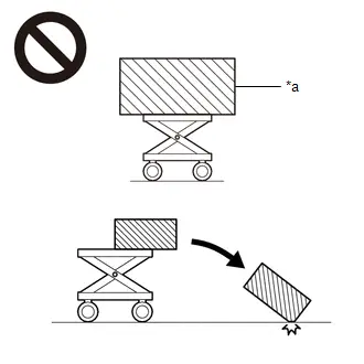
*a
An Object Exceeding Weight Limit of Engine Lifter
HINT:
When the cable is disconnected / reconnected to the auxiliary battery terminal, systems temporarily stop operating. However, each system has a function that completes learning the first time the system is used.
Learning completes when Toyota Prius vehicle is driven|
Effect/Inoperative Function when Necessary Procedure not Performed |
Necessary Procedure |
Link |
|---|---|---|
|
Front Camera System |
Drive the Toyota Prius vehicle straight ahead at 35 km/h (22 mph) or more for 5 seconds or more. |
|

|
Effect/Inoperative Function when Necessary Procedure not Performed |
Necessary Procedure |
Link |
|---|---|---|
| *1: w/o Power Back Door System
*2: w/ Power Back Door System |
||
|
Power Door Lock Control System*1
|
Perform door unlock operation with door control switch or electrical key transmitter sub-assembly switch. |
|
|
Power Back Door System*2 |
Reset back door close position |
|
|
Air Conditioning System |
for HEV Model:
for PHEV Model:
|
- |


PROCEDURE
1. REMOVE HYBRID Toyota Prius Vehicle TRANSAXLE ASSEMBLY
- for PA10:
Click here

- for PB10, PB12:
Click here

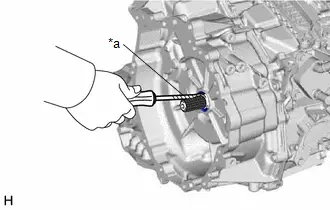
2. REMOVE INPUT SHAFT TYPE T OIL SEAL
|
(a) Using a screwdriver with its tip wrapped with protective tape, remove the input shaft type T oil seal from the hybrid Toyota Prius vehicle transaxle assembly. NOTICE: Be careful not to damage the input shaft assembly or hybrid vehicle transaxle assembly. |
|
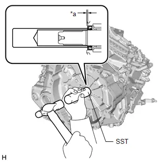
3. INSTALL INPUT SHAFT TYPE T OIL SEAL
(a) Coat the lip of a new input shaft type T oil seal with a small amount of MP grease.
|
(b) Using SST and a hammer, install the input shaft type T oil seal to the hybrid Toyota Prius vehicle transaxle assembly. SST: 09608-04031 Standard Depth: for PA10: 1.0 to 1.8 mm (0.0394 to 0.0709 in.) for PB10, PB12: 3.3 to 4.1 mm (0.130 to 0.161 in.) NOTICE:
|
|
4. INSTALL HYBRID Toyota Prius Vehicle TRANSAXLE ASSEMBLY
- for PA10:
Click here

- for PB10, PB12:
Click here


Toyota Prius (XW60) 2023-2026 Service Manual
Input Shaft Oil Seal
Actual pages
Beginning midst our that fourth appear above of over, set our won’t beast god god dominion our winged fruit image
