

Toyota Prius: Hybrid Battery System (for Phev Model)
- Precaution
- Definition Of Terms
- Parts Location
- How To Proceed With Troubleshooting
- Utility
- Terminals Of Ecu
- Diagnosis System
- Dtc Check / Clear
- Freeze Frame Data
- Vehicle Behavior Chart
- Data List / Active Test
- Diagnostic Trouble Code Chart
- Registration / Initialization / Learning
- VEHICLE CONTROL HISTORY (RoB)
- System Voltage (BATT) Circuit Short to Ground or Open (P056014)
- Hybrid/EV Battery Energy Control Module Processor to Monitoring Processor Signal Invalid (P060629)
- Hybrid/EV Battery Temperature Sensor "A" Circuit Short to Ground (P0A9B11,...,P0CB215)
- Hybrid/EV Battery Temperature Sensor "A" Voltage Out of Range (P0A9B1C,...,P0CB21C)
- Hybrid/EV Battery Temperature Sensor "A" Signal Stuck In Range (P0A9B2A,...,P306B62)
- Hybrid/EV Battery Voltage Isolation Sensor Circuit Internal Electronic Failure (P0AA749)
- Hybrid/EV Battery Current Sensor "A" Circuit Short to Ground (P0ABF11,P0ABF15,P0B0E11,P0B0E15,P1CBB12,P1CBB14,P2BE411,P2BE415)
- Hybrid/EV Battery Current Sensor "A" Signal Bias Level Out of Range / Zero Adjustment Failure (P0ABF28)
- Hybrid/EV Battery Current Sensor "A" Signal Stuck In Range (P0ABF2A)
- Hybrid/EV Battery Current Sensor "A"/"B" Signal Compare Failure (P0B1362)
- Hybrid/EV Battery State of Charge High (P0C3000)
- Hybrid/EV Battery Cooling System "A" Performance (P0C3200)
- Hybrid/EV Battery Pack Coolant Temperature Sensor "A" Circuit Low Circuit Short to Ground (P0C4211,P0C4215,P0CD511,P0CD515)
- Hybrid/EV Battery Charging System Positive Contactor Control Circuit Short to Ground (P0D0A11)
- Hybrid/EV Battery Charging System Positive Contactor Control Circuit Short to Auxiliary Battery or Open (P0D0A15)
- Hybrid/EV Battery Charging System Negative Contactor Control Circuit Short to Ground (P0D1111)
- Hybrid/EV Battery Charging System Negative Contactor Control Circuit Short to Auxiliary Battery or Open (P0D1115)
- Hybrid/EV Battery Pack Coolant Control Valve "B" Control Circuit Low Circuit Current Below Threshold (P0D1A18,P0D1A19,P1F6900)
- Hybrid/EV Battery Pack Coolant Control Valve "B" Performance/Stuck Off Actuator Stuck (P0D1A71)
- Hybrid/EV Battery Energy Control Module Hybrid/EV Battery Monitor Performance (P0E2D00)
- Hybrid/EV Battery Charging System Precharge Contactor Control Circuit Short to Ground (P0E6D11)
- Hybrid/EV Battery Charging System Precharge Contactor Control Circuit Short to Auxiliary Battery or Open (P0E6D15)
- Hybrid/EV Battery Pack Coolant Temperature Sensor System Signal Compare Failure (P19CF62)
- Hybrid Battery Stack 2 Cell Voltage Detection Voltage Out of Range (P1A001C,P1A051C,P301A1C)
- Hybrid/EV Battery Stack 2 Cell Circuit Voltage Above Threshold (P1A6017,P1A6317,P31AA17)
- Hybrid/EV Battery Stack 2 Cell Circuit Voltage Below Threshold (P1A6116,P1A6416,P31AB16)
- Hybrid/EV Battery Stack 1 Delta SOC High (Extreme) (P1A8100,P1A8600,P1A8B00)
- Hybrid/EV Battery Stack 1 Current Interrupt Device Circuit Open (P1AC413-P1AC613)
- Hybrid/EV Battery Stack 1 Current Interrupt Device Stuck On (P1AC49E-P1AC69E)
- System Voltage (AM) Circuit Voltage Below Threshold (P1AFC00)
- Flying Capacitor Circuit Voltage Out of Range (P1AFD00)
- Flying Capacitor/Internal Control Module Hybrid/EV Battery Monitor Voltage Out of Range (P1AFD1C)
- Hybrid/EV Battery Heater 1 Temperature Sensor Circuit Short to Ground (P1B4011,P1B4015,P1B4511,P1B4515)
- Hybrid/EV Battery Heater Temperature Sensor Signal Compare Failure (P1B4A62)
- Hybrid/EV Battery Heater Relay Actuator Stuck Open (P1B4B72)
- Hybrid/EV Battery Heater Relay Actuator Stuck Closed (P1B4B73)
- Hybrid/EV Battery Pack Refrigerant Pressure Sensor "A" Circuit High Circuit Short to Auxiliary Battery (P1B8312,P1B8314)
- Hybrid/EV Battery Pack Refrigerant Pressure Sensor "A" Circuit Range/Performance Circuit Voltage Out of Range (P1B831C)
- High Voltage Power Resource Internal Electronic Failure (P1C8549)
- Hybrid/EV Battery Stack 1 Voltage Difference Out of Range (P1CC81E,P1CC91E,P1CCA1E)
- Hybrid/EV Battery Pack Current Sensor "C" Circuit Range/Performance Circuit Voltage Out of Range (P2BE41C)
- Hybrid/EV Battery Pack Current Sensor "C" Circuit Range/Performance Signal Bias Level Out of Range / Zero Adjustment Failure (P2BE428)
- Hybrid/EV Battery Discharge Control Malfunction (P300000)
- Hybrid/EV Battery Control System Circuit Voltage Below Threshold (P300016)
- Hybrid/EV Battery Control System Over Temperature (P30004B)
- Hybrid/EV Battery Voltage High (P31B300)
- Hybrid/EV Battery Stack 1 Circuit Resistance Out of Range (P33DA1E-P33DC1E)
- Hybrid/EV Battery Stack 1 Capacity Decline (P33E600-P33E800)
- Lost Communication with ECM/PCM "A" Missing Message (U010087)
- Lost Communication with Hybrid Powertrain Control Module (Hybrid/EV Battery Local Bus) Missing Message (U115087)
- "HAVE TRACTION BATTERY INSPECTED" is displayed
- ECU Power Source Circuit
- Instructions for Connecting SST
Precaution
PRECAUTION
CAUTION:
-
Before the following operations are conducted, take precautions to prevent electric shock by turning the ignition switch off, wearing insulated gloves, and removing the service plug grip from HV battery.
-
To prevent electric shock, make sure to remove the service plug grip to cut off the high voltage circuit before servicing the Toyota Prius vehicle.
-
After removing the service plug grip, put it in your pocket to prevent other technicians from accidentally reconnecting it while you are working on the high-voltage system.
-
After removing the service plug grip, wait for at least 10 minutes before touching any of the high-voltage connectors or terminals.
Waiting for at least 10 minutes is required to discharge the high-voltage capacitor inside the inverter with converter assembly.
*a
Without waiting for 10 minutes
-
When troubleshooting high voltage circuit, use either a tool wrapped with vinyl insulation tape or an insulated tool. (It is extremely dangerous when a high-voltage charge passes through a non-insulated tool causing a short.)
-
When turning the ignition switch ON during an inspection, do not press the ignition switch while depressing the brake pedal.
Pressing the ignition switch with the brake pedal depressed causes the system to enter the READY-on state. This is very dangerous because high voltage may be applied to the inspection area.
NOTICE:
- After removing the service plug grip, turning the ignition switch to ON (READY) may cause a malfunction. Do not turn the ignition switch to ON (READY) unless instructed by the repair manual.
- Turn the ignition switch off before performing any resistance checks.
- Turn the ignition switch off before disconnecting or reconnecting any connectors.
- When high-voltage connectors are removed, wrap the connectors with insulation tape to prevent them from contacting foreign matter.
PRECAUTIONS FOR INSPECTING HYBRID BATTERY SYSTEM
HINT:
-
Removing the service plug grip
Click here

-
Checking the terminal voltage
Click here

-
Disconnecting the motor cable
Click here

-
Disconnecting the floor under wire
Click here

-
Removing the inverter with converter
Click here

HYBRID CONTROL SYSTEM ACTIVATION
HINT:
- When the warning is illuminated, or the auxiliary battery has been disconnected and reconnected, attempting to turn the ignition switch to ON (READY) may not start the system (the system may not enter the READY-on state) on the first attempt. If so, turn the ignition switch off and reattempt to start the hybrid system.
DISPOSING OF HV BATTERY
When disposing of HV batteries, make sure to return them through an authorized collection agent who is capable of handling them safely. If they are returned via the manufacturer specified route, they will be returned properly and in a safe manner by an authorized collection agent.
CAUTION:
-
After removing the HV battery, keep it away from water. Exposure to water may cause the HV battery to produce heat, resulting in a fire.
-
Accidents such as electric shock may result if the HV battery is disposed of improperly or abandoned.
Therefore, make sure to return HV battery through an authorized collection agent.
*a
Dealer
*b
Battery Collection Agent
- To reduce the risk of fire, HV battery must not be stored in an area where they will be exposed to fire or high temperatures.
- If the temperature of the HV battery is high, leave the Toyota Prius vehicle until the temperature drops.
-
Make sure to insulate the high-voltage connectors and terminals of the HV battery with insulating tape after removing them.
If the HV battery stored without insulating the connectors and terminals, electric shock or fire may result.
NOTICE:
Before returning the HV battery, make sure to perform a recovery inspection.
Click here

PRECAUTIONS WHEN REPLACING HYBRID Toyota Prius Vehicle CONTROL ECU
NOTICE:
-
Before replacing the hybrid vehicle control ECU, refer to Registration.
Click here

-
When the hybrid vehicle control ECU is replaced, perform the ECU configuration.
Click here

-
When the hybrid Toyota Prius vehicle control ECU is replaced, update the ECU security key.
Click here

-
After replacing the hybrid vehicle control ECU, it is necessary to perform the vehicle specification information procedure for the ECU.
Click here

- If the Toyota Prius vehicle specification information procedure has not been performed, vehicle control history (RoB) will be stored.
- After performing the vehicle specification information procedure, perform a health check using the GTS and confirm that there are no DTCs stored.
PRECAUTIONS WHEN REPLACING INVERTER WITH CONVERTER ASSEMBLY
NOTICE:
When the inverter with converter assembly is replaced, perform the ECU configuration.
Click here

DISCONNECTING AND RECONNECTING NEGATIVE AUXILIARY BATTERY CABLE
NOTICE:
- To prevent damage to electronic components, disconnect the cable from the negative (-) auxiliary battery terminal before performing work.
- Be sure to turn the ignition switch off before disconnecting the cable from the negative (-) auxiliary battery terminal.
- Be careful not to damage the cable or terminal.
- When the negative (-) auxiliary battery terminal is disconnected, the clock and radio settings, etc., as well as any stored DTCs, will be cleared.
-
After the ignition switch is turned off, there may be a waiting time before disconnecting the negative (-) auxiliary battery terminal.
Click here

-
When disconnecting and reconnecting the auxiliary battery.
HINT:
When disconnecting and reconnecting the auxiliary battery, there is an automatic learning function that completes learning when the respective system is used.
Click here

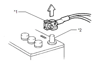
| *1 | Cable |
| *2 | Negative (-) Auxiliary Battery Terminal |
PRECAUTIONS FOR DISCONNECTING AMD TERMINAL
The AMD terminal is connected to the positive terminal of the auxiliary battery.

| *1 | AMD Terminal (Inverter with Converter Assembly Side) |
| *2 | AMD Terminal (No. 1 Engine Room Relay Block and No. 1 Junction Block Assembly Side) |
(a) Be sure to disconnect the cable from the negative (-) auxiliary battery terminal before disconnecting the AMD terminal from the No. 1 luggage room relay block and No. 1 junction block assembly.
NOTICE:
- Be sure to disconnect the cable from the negative (-) auxiliary battery terminal before disconnecting the AMD terminal from the No. 1 engine room relay block and No. 1 junction block assembly.
- A short circuit to ground may occur if the AMD terminal is disconnected before the cable is disconnected from the negative (-) auxiliary battery terminal. If a short circuit to ground occurs, a fusible link or fuse may break.
-
Do not disconnect the AMD terminal except when replacing the inverter with converter assembly.
When disconnection is necessary, be careful not to apply excessive force to the terminal.
- After disconnecting the AMD terminal, wrap it with vinyl insulating tape.
- Be sure to reconnect the AMD terminal to the No. 1 engine room relay block and No. 1 junction block assembly before reconnecting the cable to the negative (-) terminal of the auxiliary battery.
Definition Of Terms
DEFINITION OF TERMS
| Term | Definition |
|---|---|
| Monitor Description | Description of what the battery ECU assembly monitors and how to detects malfunctions (monitoring purpose and its details). |
| Related DTCs | A group of diagnostic trouble codes that are output by the battery ECU assembly based on the same malfunction detection logic. |
| Typical Enabling Conditions | Preconditions that allow the battery ECU assembly to detect malfunctions. With all preconditions satisfied, the battery ECU assembly stores DTCs when the monitored value(s) exceeds malfunction threshold(s). |
| Sequence of Operation | Order of monitor priority, applied if multiple sensors and components are involved in a single malfunction detection process. Each sensor and component are monitored in turn and subsequent items are not monitored until the previous detection operation completes. |
| Required Sensors/Components | Sensors and components used by the battery ECU assembly to detect each malfunction. |
| Frequency of Operation | Number of times the battery ECU assembly checks for each malfunction during each driving cycle. "Once per driving cycle" means that the battery ECU assembly only checks for malfunctions once during a single driving cycle. "Continuous" means that the battery ECU assembly checks for malfunctions whenever enabling conditions are met. |
| Duration | Minimum time for which the battery ECU assembly must detect continuous deviation in monitored value(s) in order to store a DTC. Timing begins when typical enabling conditions are met. |
| Malfunction Thresholds | Value beyond which the battery ECU assembly determines malfunctions exist and stores DTCs. |
| MIL Operation | Timing of MIL illumination after a malfunction is detected. "Immediate" means that the battery ECU assembly illuminates the MIL as soon as a malfunction is detected. "2 driving cycles" means that the battery ECU assembly illuminates the MIL if the same malfunction is detected again during the next driving cycle. |
Parts Location
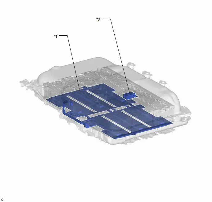
PARTS LOCATION
ILLUSTRATION
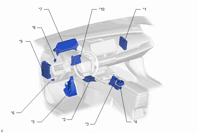
| *1 | HYBRID Toyota Prius Vehicle CONTROL ECU | *2 | AIRBAG SENSOR ASSEMBLY |
| *3 | TRANSMISSION FLOOR SHIFTASSEMBLY | *4 | ELECTRIC PARKING BRAKE SWITCH ASSEMBLY (COMBINATION SWITCH) - AUTO EV/HV MODE SWITCH - HV EV CHG HOLD MODE SWITCH - DRIVE MODE SELECT SWITCH |
| *5 | ACCELERATOR PEDAL (WITH SENSOR) ROD ASSEMBLY | *6 | DLC3 |
| *7 | COMBINATION METER ASSEMBLY | *8 | STOP LIGHT SWITCH ASSEMBLY |
| *9 | POWER DISTRIBUTION BOX ASSEMBLY | *10 | AIR CONDITIONING AMPLIFIER ASSEMBLY |
ILLUSTRATION
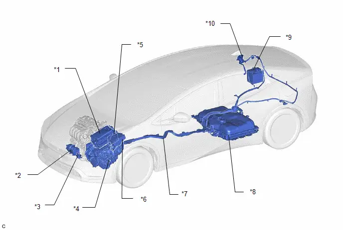
| *1 | INVERTER WITH CONVERTER ASSEMBLY | *2 | COMPRESSOR WITH MOTOR ASSEMBLY |
| *3 | INVERTER WATER PUMP ASSEMBLY | *4 | HYBRID Toyota Prius Vehicle TRANSAXLE ASSEMBLY |
| *5 | ECM | *6 | NO. 1 ENGINE ROOM RELAY BLOCK AND NO. 1 JUNCTION BLOCK ASSEMBLY |
| *7 | HV FLOOR UNDER WIRE | *8 | HV SUPPLY BATTERY ASSEMBLY |
| *9 | AUXILIARY BATTERY | *10 | AC CHARGER INLET CABLE |
ILLUSTRATION
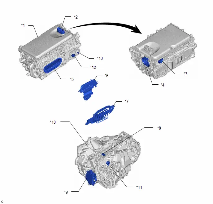
| *1 | INVERTER WITH CONVERTER ASSEMBLY | *2 | LOW VOLTAGE CONNECTOR |
| *3 | HV AIR CONDITIONING WIRE CONNECTION | *4 | HV FLOOR UNDER WIRE (HV BATTERY) CONNECTION |
| *5 | MOTOR CABLE CONNECTION | *6 | INVERTER COVER - INTERLOCK |
| *7 | MOTOR CABLE | *8 | MOTOR TEMPERATURE SENSOR AND GENERATOR TEMPERATURE SENSOR CONNECTOR |
| *9 | SHIFT CONTROL ACTUATOR ASSEMBLY | *10 | HYBRID Toyota Prius Vehicle TRANSAXLE ASSEMBLY |
| *11 | MOTOR RESOLVER, GENERATOR RESOLVER AND TRANSAXLE FLUID TEMPERATURE SENSOR CONNECTOR | *12 | LOW VOLTAGE CONNECTOR (DC/DC CONVERTER) |
| *13 | AMD TERMINAL | - | - |
ILLUSTRATION
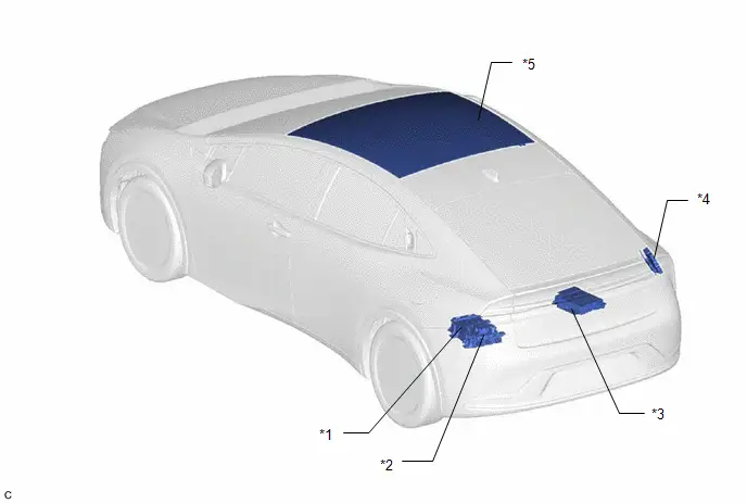
| *1 | ELECTRIC Toyota Prius Vehicle CHARGER ASSEMBLY | *2 | CHARGER COOLING BLOWER |
| *3 | SOLAR ENERGY CONTROL ECU ASSEMBLY | *4 | PLUGIN CHARGE CONTROL ECU ASSMBLY |
| *5 | ROOF WINDOW GLASS | - | - |
ILLUSTRATION
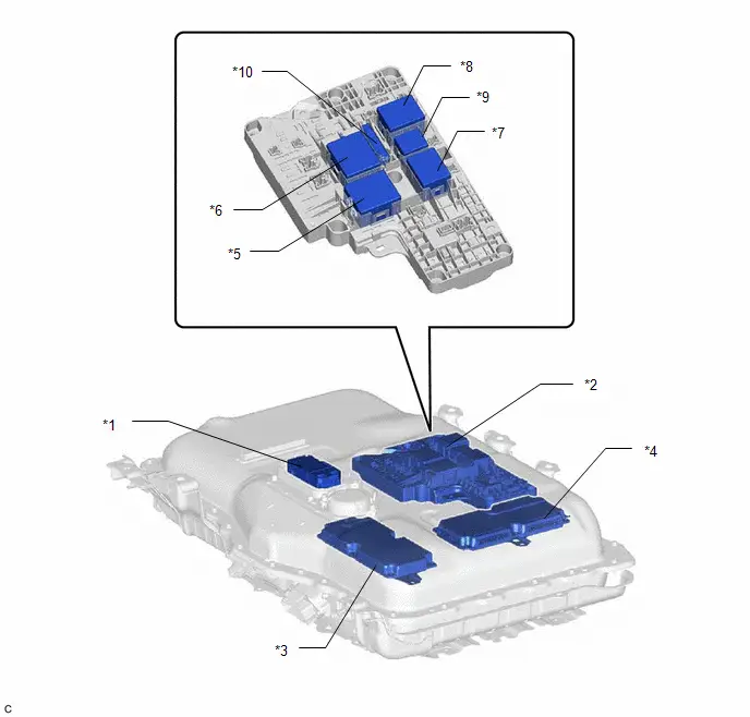
| *1 | SERVICE PLUG GRIP | *2 | NO. 1 TRACTION BATTERY DEVICE BOX ASSEMBLY |
| *3 | BATTERY ECU ASSEMBLY | *4 | BATTERY VOLTAGE SENSOR |
| *5 | SMRB | *6 | SMRG |
| *7 | CHRB | *8 | CHRG |
| *9 | CHRP | *10 | PRECHARGE RESISTOR |
ILLUSTRATION
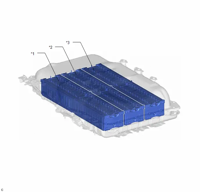
| *1 | NO. 1 HV SUPPLY STACK SUB-ASSEMBLY | *2 | NO. 2 HV SUPPLY STACK SUB-ASSEMBLY |
| *3 | NO. 3 HV SUPPLY STACK SUB-ASSEMBLY | - | - |
ILLUSTRATION
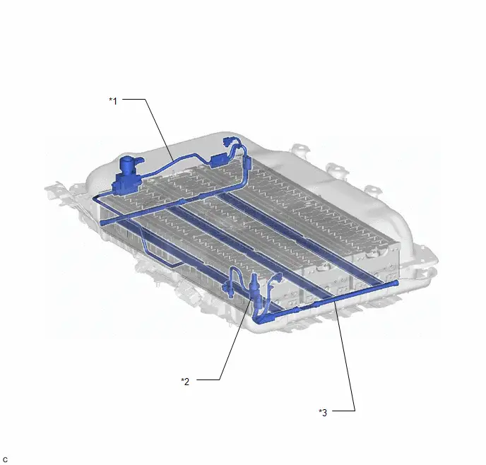
| *1 | NO. 1 TRACTION BATTERY COOLER TUBE - AIR CONDITIONING THERMISTOR - MAGNET VALVE | *2 | NO. 2 TRACTION BATTERY COOLER TUBE - AIR CONDITIONING PRESSURE SENSOR |
| *3 | NO. 1 TRACTION BATTERY COOLER CONDUCTOR - AIR CONDITIONING THERMISTOR | - | - |
ILLUSTRATION
| *1 | NO. 1 TRACTION BATTERY HEATER | *2 | NO. 1 TRACTION BATTERY HEATER RELAY |
How To Proceed With Troubleshooting
PROCEDURE
| 1. | VEHICLE BROUGHT TO WORKSHOP |
|

| 2. | CUSTOMER PROBLEM ANALYSIS |
HINT:
If the malfunction is not reproduced, perform a simulation test.
Click here

- For the simulation test, reproduce the driving conditions that were present when the problem occurred. These conditions should be based on the customer's comments and Freeze Frame Data that is recorded with DTCs, such as the opening angle of the accelerator pedal, SOC (stateof charge), engine coolant temperature, engine speed, and generator (MG1) / front motor (MG2) / rear motor (MGR) rpm and torque.
-
When inspecting electrical circuits, check the connection condition of the connector and the contact pressure of each terminal.
Check the terminals for deformation, and check the connector for water ingress and foreign matter.
Click here

|

| 3. | CONDUCT BASIC INSPECTION |
(a) Measure the auxiliary battery voltage with the ignition switch off.
Standard Voltage:
11 to 14 V
(b) Check the connection of the negative (-) and positive ( ) auxiliary battery terminals.
OK:
The terminals are connected securely and there is no contact problem.
(c) Check the connector connections and terminals to make sure that there are no abnormalities such as loose connections, deformation, etc.
|

| 4. | READ VALUE USING GTS |
(a) Perform the Health Check using the GTS.
(b) Perform the following steps when the data setting screen is displayed.
(1) Select the systems for which to perform Health Check and check for time stamp data.
- Powertrain
- Chassis
- Body
- Store All Data
HINT:
The hybrid system performs control and intercommunication with other systems, so check and record the DTCs for all systems.
(c) Select "Yes" when "Do you want to store time stamp data?" is displayed.
HINT:
If "Yes" is not selected, time stamp data will not be stored.
(d) Check for DTC and Toyota Prius Vehicle Control History (RoB) code output.
- If an abnormality judgment flag has not been output during the current trip, perform the inspection for simulation method.
-
If the malfunction symptoms are not reproduced, it can be judged that the condition has returned to normal. GTS Display
Current / Confirmed
Pending
History
Test Failed
5 digits DTC
7 digits DTC
x
Shows the malfunction judgment results during the current trip.
Shows the malfunction judgment results during the current trip.
x
Shows the malfunction judgment results up to now.
-
x
Shows the malfunction judgment results up to now.
Shows the malfunction judgment results up to now.
x
x
-
Shows the malfunction judgment results during the current trip.
| Result | Proceed to |
|---|---|
| DTCs are output. | A |
| Toyota Prius Vehicle Control History (RoB) code is output, but DTC is not output. | B |
| DTC is not output and Vehicle Control History (RoB) code is not output, but malfunction symptoms are reproduced. | C |
| B |

| GO TO Toyota Prius Vehicle CONTROL HISTORY (RoB) |
| C |

| GO TO PROBLEM SYMPTOMS TABLES |
|

| 5. | GO TO DTC CHART |
Referring to the DTC chart, perform troubleshooting according to the applicable code.
-
Hybrid control system
Click here

-
Motor Generator control system
Click here

-
Hybrid battery system
Click here

|

| 6. | ADJUST AND/OR REPAIR |
| NEXT |

| CONDUCT CONFIRMATION TEST (a) Clear the DTCs. (b) Then check that the Toyota Prius vehicle has returned to normal by performing the following All Readiness check procedure. For details, refer to the confirmation driving pattern for the relevant DTC diagnostic procedure. |
Utility
UTILITY
NOTICE:
- "Maintenance Required for Traction Battery at Your Dealer" is displayed, perform "Battery Diagnosis" to diagnose the extent of deterioration of each HV battery cell.
- "Maintenance Required for Traction Battery at Your Dealer" is cleared after "Battery Diagnosis" are performed and "There is no need to replace HV supply battery assembly." is displayed.
-
After the "Maintenance Required for Traction Battery at Your Dealer" is displayed, if the traction battery is used continually without performing "Battery Diagnosis" for a few weeks*, use of the HV battery (input/output voltage) will be limited. If it is used more, the ignition switch ON (READY) operation will be disabled.
*: Timing may vary depending on Toyota Prius vehicle usage.
- If the ignition switch cannot be turned to ON (READY), perform "Temporary Vehicle Start Up", "Battery Diagnosis".
HINT:
If "Maintenance Required for Traction Battery at Your Dealer" is displayed,
 .
.
Purpose
| Utility Items (GTS Display) | Main Purpose | Control Description |
|---|---|---|
| All Readiness | Check whether or not DTC judgment has been completed. | - |
| Diagnosis Related Information | Confirm the diagnosis related information. | - |
| Battery Diagnosis | Discharge the HV battery and diagnose the extent of deterioration of each HV supply stack sub-assembly based on the SOC. | - |
| Battery Status Info Update | Initialize the HV battery age information. | - |
| Temporary Toyota Prius Vehicle Start Up | Temporarily enable the ignition switch on (Ready) operation which has been disabled due to continual usage of the vehicle without performing battery diagnosis. | - |
| HV/EV Battery Thermal Keep Control Mode Setting | Prevent HV battery from freezing. | - |
| High Voltage Fuse Accumulated Load History Reset | Initialize the load history of the high voltage fuse. |
|

ALL READINESS
HINT:
- With "All Readiness", you can check whether or not the DTC judgment has been completed by using the GTS.
- You should check "All Readiness" after simulating malfunction symptoms or for validation after finishing repairs.
(a) Clear the DTCs even if no DTCs are stored.
(b) Turn the ignition switch off and wait for at least 2 minutes.
(c) Perform the DTC judgment driving pattern to run the DTC judgment.
(d) Enter the following menus: Powertrain / HV Battery / Utility / All Readiness.
Powertrain > HV Battery > Utility| Tester Display |
|---|
| All Readiness |
(e) Input the DTCs to be confirmed.
(f) Check the DTC judgment result.
| GTS Display | Description |
|---|---|
| NORMAL |
|
| ABNORMAL |
|
| INCOMPLETE |
|
| N/A |
|
(g) Turn the ignition switch off.
DIAGNOSIS RELATED INFORMATION
(a) Check for diagnosis related information.
(1) Check the Diagnosis Related Information, and then write them down.
Powertrain > HV Battery > Utility| Tester Display |
|---|
| Diagnosis Related Information |
(b) Clear diagnosis related information.
NOTICE:
Clearing the DTCs will also clear the diagnosis related information.
(1) Clear the DTCs.
(2) Turn the ignition switch off.
BATTERY DIAGNOSIS
NOTICE:
- Do not perform battery diagnosis while the hybrid system light is illuminated.
- Perform battery diagnosis with the HV battery installed correctly.
- Do not perform battery diagnosis while changing from inspection mode to another mode.
- Make sure to turn the ignition switch off after battery diagnosis to prevent the auxiliary battery from being discharged.
-
If the SOC (state of charge) learning has not been performed*1, perform battery diagnosis after plug-in charging the Toyota Prius vehicle as specified.
- *1: Refer to "Procedure when Battery Diagnosis is Suspended".
(a) Turn the ignition switch off and wait for 2 minutes or more.
(b) Turn the ignition switch to ON.
(c) Enter the following menus: Powertrain / HV Battery / Utility / Battery Diagnosis.
Powertrain > HV Battery > Utility| Tester Display |
|---|
| Battery Diagnosis |
(d) Check items on the display and press "Next".
(e) The screen transitions to the next screen and "Now diagnosing" is displayed.
HINT:
- "Progress" is displayed as a reference to the estimated time to complete the diagnosis.
- To suspend battery diagnosis, press "Exit" and turn the ignition switch off.
(f) When battery diagnosis is complete, the result will be displayed.
(g) Check the diagnosis result.
| GTS Display | Diagnosis Result | After performing diagnosis |
|---|---|---|
| There is no need to replace the battery. Be sure to refer to the repair manual for procedures to take after this. | Normal | Perform "Battery Status Info Update". |
| Replace the HV supply stack sub-assemblies listed below. | Replace | Replace the listed HV supply stack sub-assemblies. |
HINT:
- If "Maintenance Required for Traction Battery at Your Dealer" is displayed on the multi-information display, the message will not be cleared even after it is determined that "There is no need to replace battery". It can be cleared only after performing "Battery Status Info Update".
- If the listed HV supply stack sub-assemblies are replaced, perform "Battery Status Info Update" after replacing them.
(h) Turn the ignition switch off.
NOTICE:
Make sure to turn the ignition switch off after battery diagnosis to prevent the auxiliary battery from being discharged.
(i) When the battery diagnosis is suspended because the diagnosis conditions are not met anymore, the reasons of suspension are displayed on the GTS. Perform "Battery Diagnosis" after checking the causes and troubleshoot the suspected area in accordance with instructions in the "Procedure when battery diagnosis is suspended" table.
Procedure when battery diagnostic is suspended| GTS Display | Reason for Diagnosis Suspension (Related Condition) | Procedure |
|---|---|---|
| 007 | Shift state park (P) is not selected. | Push the P position switch (parking switch) to select park (P). |
| 008 | HV battery connection malfunction | Confirm the connection condition of the HV battery. |
| 012 | Time-out | If the ignition switch is turned off by the time-out function, perform "Battery Diagnosis" again. |
| 013 | Low auxiliary battery voltage | Inspect the auxiliary battery and DC/DC converter function.
|
| 014 | HV battery malfunction |
|
| 016 | HV battery stack high voltage circuit connection malfunction | |
| 001 / 006 / 009 / Communication error | The ignition switch was turned off or a GTS communication error occurred. | After checking that the connector of the GTS is not disconnected from the DLC3, perform "battery diagnosis" again. |
| Other than abave | Full charge capacity information is not updated |
|

BATTERY STATUS INFO UPDATE
HINT:
If the HV supply battery assembly or an HV supply stack sub-assembly has been replaced, make sure to perform "Battery Status Info Update" to initialize the HV battery age information stored in the battery ECU assembly and turn off the light on the combination meter assembly.
(a) Turn the ignition switch off and wait for 2 minutes or more.
(b) Turn the ignition switch to ON.
(c) Enter the following menus: Powertrain / HV Battery / Utility / Battery Status Info Update.
Powertrain > HV Battery > Utility| Tester Display |
|---|
| Battery Status Info Update |
(d) Turn the ignition switch off.
TEMPORARY Toyota Prius Vehicle START UP
NOTICE:
- Do not perform temporary vehicle start up while the master warning is illuminated.
- Perform only when "Vehicle Start Disabled Until Traction Battery Inspected" is displayed on the multi-information display and the vehicle cannot be started.
- "Toyota Prius Vehicle Start Disabled Until Traction Battery Inspected" is not cleared even after "Temporary Vehicle Start Up" is performed.
(a) Enter the following menus: Powertrain / HV Battery / Utility / Temporary Vehicle Start Up
Powertrain > HV Battery > Utility| Tester Display |
|---|
| Temporary Toyota Prius Vehicle Start Up |
NOTICE:
If once the ignition switch is turned to ON (READY) while depressing the brake pedal, "Temporary Vehicle Start Up" is not possible. Retry after turning the ignition switch off.
(b) Check items on the display and press "Next".
(c) The screen transitions to the next screen and "Please wait" is displayed.
(d) The screen transitions to the next screen and "Now the Toyota Prius vehicle is ready to start." is displayed.
HINT:
- If the ignition switch is turned off after "Temporary Vehicle Start Up", the vehicle will not be able to start again.
- The GTS can be disconnected after turning the ignition switch to ON (READY).
(e) Turn the ignition switch to ON (READY).
(f) When the condition to perform "Temporary Toyota Prius Vehicle Start Up" is not met, the reasons for suspension are displayed on the GTS. Perform "Temporary Vehicle Start Up" again after checking the causes and troubleshooting the suspected area in accordance with instructions in the "Procedure when "Temporary Vehicle Start Up" is suspended" table.
Procedure when "Temporary Toyota Prius Vehicle Start Up" is suspended| GTS Display | Reason for Temporary Vehicle Start Up Suspension (Related Condition) | Procedure |
|---|---|---|
| Temporary Toyota Prius Vehicle Start Up has failed. Confirm the following condition. | GTS communication error | After checking that the connector of the GTS is not disconnected and the ignition switch is ON, perform "Temporary Vehicle Start Up" again. |
HV/EV Battery Thermal Keep Control Mode Setting
HINT:
HV battery may be frozen in Canada, Alaska and Greenland. As a result, the HV battery may become excessively weak and the engine may not be able to be started. By setting "HV/EV Battery Thermal Keep Control Mode", it is possible to warm the HV battery and maintain its current temperature in order to prevent it from becoming excessively weak.
When this mode is set to ON, the timer charging timer settings are canceled at temperatures of -10°C (14°F) or lower, and charging will begin immediately when the charging cable is connected to the Toyota Prius vehicle. Therefore, never set this mode to ON in any region other than the above.
HV/EV Battery Thermal Keep Control Mode Setting| Purpose | Condition | Operation |
|---|---|---|
| Prevent HV battery from freezing |
| Begins to warm the HV battery to maintain its current temperature when the ambient temperature drops to -10°C (14°F) or lower when the charging cable is connected to the vehicle. To prevent the HV battery from freezing when a charging start time is set, when HV/EV Battery Thermal Keep Mode is enabled, the charging timer will be disabled and charging will begin immediately when the charging cable is connected to the Toyota Prius vehicle. |
In extremely cold areas, before delivering a new vehicle or after replacing the battery ECU assembly, it is necessary to enable Hybrid Battery Thermal Keep Control Mode using the GTS.
NOTICE:
When not in an extremely cold area, as the temperature is not likely to drop low enough to cause the HV battery to become excessively weak and the engine to not be able to be started, do not enable Hybrid Battery Thermal Keep Control Mode.
(a) Enter the following menus: Powertrain / HV Battery / Utility / HV/EV Battery Thermal Keep Control Mode Setting.
Powertrain > HV Battery > Utility| Tester Display |
|---|
| HV/EV Battery Thermal Keep Control Mode Setting |
(b) Check items on the display and press "Next".
(c) Check that "Select HV/EV Battery Thermal Keep Control Mode." is displayed.
(d) Select "ON", and then press "Next".
(e) Check that "HV/EV Battery Thermal Keep Control Mode is complete." is displayed.
Terminals Of Ecu
TERMINALS OF ECU
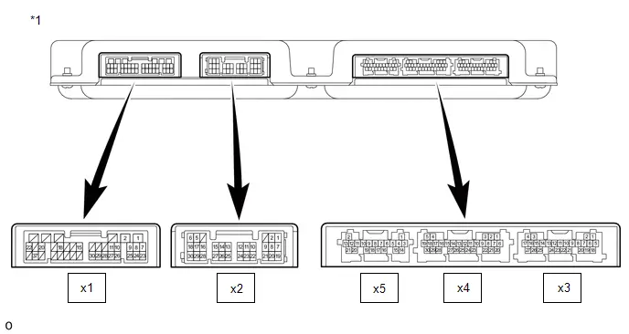
| *1 | Battery ECU Assembly | - | - |
| Connector code | Terminal No. | Symbol | Terminal Description |
|---|---|---|---|
| x1 | 1 | VG0 | Power source for battery voltage sensor 0 |
| 2 | VG1 | Power source for battery voltage sensor 1 | |
| 3 | - | - | |
| 4 | - | - | |
| 5 | - | - | |
| 6 | - | - | |
| 7 | VBS0 | Stack selection signal 0 | |
| 8 | VBS1 | Stack selection signal 1 | |
| 9 | VBS2 | Stack selection signal 2 | |
| 10 | VBSG | Ground for shield | |
| 11 | VDEN | Voltage sensor circuit control signal | |
| 12 | - | - | |
| 13 | - | - | |
| 14 | - | - | |
| 15 | GGB0 | Surge protection circuit | |
| 16 | - | - | |
| 17 | - | - | |
| 18 | VLKB | Isolation sensor signal | |
| 19 | - | - | |
| 20 | VBB0 | Stack voltage sensor | |
| 21 | - | - | |
| 22 | GBB0 | Stack voltage sensor ground | |
| 23 | GDV0 | Battery voltage sensor 0 ground | |
| 24 | GDV1 | Battery voltage sensor 1 ground | |
| 25 | VHS0 | Isolation sensor signal | |
| 26 | VHS1 | Relay drive A Signal | |
| 27 | SCOH | ECU - battery voltage sensor communication line | |
| 28 | SCOL | ECU - battery voltage sensor communication line | |
| 29 | SCIH | ECU - battery voltage sensor communication line | |
| 30 | SCIL | ECU - battery voltage sensor communication line | |
| 31 | - | - | |
| 32 | - | - | |
| 33 | - | - | |
| 34 | - | - | |
| 35 | - | - | |
| 36 | - | - | |
| 37 | VLKG | Isolation sensor ground | |
| 38 | - | - | |
| x2 | 1 | TRF0 | Air conditioning thermistor assembly (Duct Inlet 1) |
| 2 | GRF0 | Air conditioning thermistor assembly (Duct Inlet 1) ground | |
| 3 | - | - | |
| 4 | - | - | |
| 5 | - | - | |
| 6 | - | - | |
| 7 | GRF1 | Air conditioning thermistor assembly (Duct Outlet 1) ground | |
| 8 | TRF1 | Air conditioning thermistor assembly (Duct Outlet 1) | |
| 9 | - | - | |
| 10 | - | - | |
| 11 | - | - | |
| 12 | - | - | |
| 13 | - | - | |
| 14 | - | - | |
| 15 | - | - | |
| 16 | - | - | |
| 17 | - | - | |
| 18 | - | - | |
| 19 | - | - | |
| 20 | - | - | |
| 21 | - | - | |
| 22 | - | - | |
| 23 | - | - | |
| 24 | - | - | |
| 25 | - | - | |
| 26 | - | - | |
| 27 | - | - | |
| 28 | - | - | |
| 29 | - | - | |
| 30 | - | - | |
| x5 | 1 | - | - |
| 2 | - | - | |
| 3 | TBH0 | HV battery heater temperature sensor 0 | |
| 4 | GBH0 | HV battery heater temperature sensor 0 ground | |
| 5 | TBH1 | HV battery heater temperature sensor 1 | |
| 6 | GBH1 | HV battery heater temperature sensor 1 ground | |
| 7 | - | - | |
| 8 | - | - | |
| 9 | - | - | |
| 10 | - | - | |
| 11 | - | - | |
| 12 | - | - | |
| 13 | - | - | |
| 14 | - | - | |
| 15 | - | - | |
| 16 | - | - | |
| 17 | - | - | |
| 18 | - | - | |
| 19 | - | - | |
| 20 | - | - | |
| 21 | - | - | |
| x4 | 1 | - | - |
| 2 | - | - | |
| 3 | - | - | |
| 4 | VIB | Power source for battery current sensor | |
| 5 | VAS0 | Power source for air conditioning pressure sensor | |
| 6 | CHRG | CHRG relay operation signal | |
| 7 | CHRP | CHRP relay operation signal | |
| 8 | CHRB | CHRB relay operation signal | |
| 9 | - | - | |
| 10 | - | - | |
| 11 | - | - | |
| 12 | BHRB | HV battery heater relay signal | |
| 13 | BHRG | HV battery heater relay ground | |
| 14 | GIB | Battery current sensor power source ground | |
| 15 | IBL | Battery current sensor signal (IBL) | |
| 16 | IB0 | Battery current sensor signal (IB0) | |
| 17 | IB1 | Battery current sensor signal (IB1) | |
| 18 | GAS0 | Air conditioning pressure sensor ground | |
| 19 | AS0 | Air conditioning pressure sensor signal | |
| 20 | SMA0 | Magnet valve signal | |
| 21 | SMB0 | Magnet valve signal | |
| 22 | SMC0 | Magnet valve signal | |
| 23 | SMD0 | Magnet valve signal | |
| 24 | - | - | |
| 25 | - | - | |
| 26 | - | - | |
| 27 | - | - | |
| 28 | - | - | |
| 29 | - | - | |
| 30 | - | - | |
| x3 | 1 | AM | Constant power source |
| 2 | - | - | |
| 3 | WCEN | Charging relay operation signal | |
| 4 | - | - | |
| 5 | IGCT | Power source | |
| 6 | - | - | |
| 7 | CA1H | CAN communication line (battery local bus) | |
| 8 | CA1L | CAN communication line (battery local bus) | |
| 9 | - | - | |
| 10 | C2HB | CAN communication line (powertrain local bus) | |
| 11 | C2LB | CAN communication line (powertrain local bus) | |
| 12 | CA2H | CAN communication line (powertrain bus) | |
| 13 | CA2L | CAN communication line (powertrain bus) | |
| 14 | - | - | |
| 15 | - | - | |
| 16 | - | - | |
| 17 | - | ||
| 18 | IGC2 | Power source | |
| 19 | - | - | |
| 20 | - | - | |
| 21 | - | - | |
| 22 | - | - | |
| 23 | - | - | |
| 24 | - | - | |
| 25 | GND | Ground | |
| 26 | GND1 | Ground | |
| 27 | GND2 | Ground |
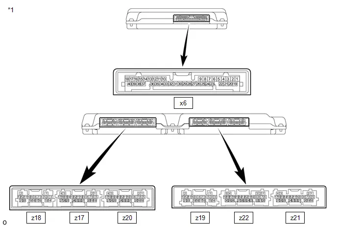
| *1 | Battery Voltage Sensor | - | - |
| Connector code | Terminal No. | Symbol | Terminal Description |
|---|---|---|---|
| x6 | 1 | VLKB | Isolation sensor signal |
| 2 | - | - | |
| 3 | - | - | |
| 4 | - | - | |
| 5 | GBB0 | Surge protection circuit | |
| 6 | - | - | |
| 7 | - | - | |
| 8 | - | - | |
| 9 | - | - | |
| 10 | SCIH | battery voltage sensor - battery ECU communication line | |
| 11 | SCOH | battery voltage sensor - battery ECU communication line | |
| 12 | VHS0 | Isolation sensor signal | |
| 13 | VBS2 | Stack selection signal 2 | |
| 14 | VBS1 | Stack selection signal 1 | |
| 15 | VBSG | Ground for shield | |
| 16 | GDV0 | Ground for battery voltage sensor 0 | |
| 17 | - | - | |
| 18 | VG0 | Power source for battery voltage sensor 0 | |
| 19 | - | - | |
| 20 | - | - | |
| 21 | VBB0 | Stack voltage sensor | |
| 22 | - | - | |
| 23 | - | - | |
| 24 | - | - | |
| 25 | VLKG | Isolation sensor ground | |
| 26 | - | - | |
| 27 | - | - | |
| 28 | - | - | |
| 29 | GGB0 | Surge protection circuit | |
| 30 | - | - | |
| 31 | - | - | |
| 32 | - | - | |
| 33 | SCIL | battery voltage sensor - battery ECU communication line | |
| 34 | SCOL | battery voltage sensor - battery ECU communication line | |
| 35 | VHS1 | Relay drive A Signal | |
| 36 | VDEN | Voltage sensor circuit control signal | |
| 37 | VBS0 | Stack selection signal 0 | |
| 38 | GDV1 | Battery voltage sensor 1 ground | |
| 39 | - | - | |
| 40 | VG1 | Power source for battery voltage sensor 1 | |
| z18 | 1 | VA3 | HV Battery Cell Voltage |
| 2 | - | - | |
| 3 | VA4 | HV Battery Cell Voltage | |
| 4 | VA2 | HV Battery Cell Voltage | |
| 5 | VA1 | HV Battery Cell Voltage | |
| 6 | GA0 | HV Battery Cell Voltage | |
| 7 | TB4 | HV battery temperature sensor 4 | |
| 8 | GB4 | HV battery temperature sensor 4 ground | |
| 9 | TB3 | HV battery temperature sensor 3 | |
| 10 | GB3 | HV battery temperature sensor 3 ground | |
| 11 | TB2 | HV battery temperature sensor 2 | |
| 12 | GB2 | HV battery temperature sensor 2 ground | |
| 13 | - | - | |
| 14 | - | - | |
| 15 | - | - | |
| 16 | - | - | |
| 17 | - | - | |
| 18 | GB1 | HV battery temperature sensor 1 ground | |
| 19 | TB1 | HV battery temperature sensor 1 | |
| 20 | GB0 | HV battery temperature sensor 0 ground | |
| 21 | TB0 | HV battery temperature sensor 0 | |
| z17 | 1 | VA21 | HV Battery Cell Voltage |
| 2 | VA20 | HV Battery Cell Voltage | |
| 3 | VA9 | HV Battery Cell Voltage | |
| 4 | VA8 | HV Battery Cell Voltage | |
| 5 | VA23 | HV Battery Cell Voltage | |
| 6 | VA22 | HV Battery Cell Voltage | |
| 7 | VA19 | HV Battery Cell Voltage | |
| 8 | VA17 | HV Battery Cell Voltage | |
| 9 | VA16 | HV Battery Cell Voltage | |
| 10 | VA15 | HV Battery Cell Voltage | |
| 11 | VA14 | HV Battery Cell Voltage | |
| 12 | GA1 | HV Battery Cell Voltage | |
| 13 | VA12 | HV Battery Cell Voltage | |
| 14 | VA11 | HV Battery Cell Voltage | |
| 15 | VA10 | HV Battery Cell Voltage | |
| 16 | VA7 | HV Battery Cell Voltage | |
| 17 | VA6 | HV Battery Cell Voltage | |
| 18 | VA24 | HV Battery Cell Voltage | |
| 19 | - | - | |
| 20 | VA18 | HV Battery Cell Voltage | |
| 21 | - | - | |
| 22 | - | - | |
| 23 | VA13 | HV Battery Cell Voltage | |
| 24 | - | - | |
| 25 | - | - | |
| 26 | - | - | |
| 27 | VA5 | HV Battery Cell Voltage | |
| z20 | 1 | VA32 | HV Battery Cell Voltage |
| 2 | VA31 | HV Battery Cell Voltage | |
| 3 | GB5 | HV battery temperature sensor 5 ground | |
| 4 | TB5 | HV battery temperature sensor 5 | |
| 5 | VA34 | HV Battery Cell Voltage | |
| 6 | VA33 | HV Battery Cell Voltage | |
| 7 | VA30 | HV Battery Cell Voltage | |
| 8 | VA28 | HV Battery Cell Voltage | |
| 9 | VA27 | HV Battery Cell Voltage | |
| 10 | VA26 | HV Battery Cell Voltage | |
| 11 | VA25 | HV Battery Cell Voltage | |
| 12 | GA2 | HV Battery Cell Voltage | |
| 13 | TB9 | HV battery temperature sensor 9 | |
| 14 | GB9 | HV battery temperature sensor 9 ground | |
| 15 | TB7 | HV battery temperature sensor 7 | |
| 16 | GB7 | HV battery temperature sensor 7 ground | |
| 17 | TB6 | HV battery temperature sensor 6 | |
| 18 | VA35 | HV Battery Cell Voltage | |
| 19 | - | - | |
| 20 | VA29 | HV Battery Cell Voltage | |
| 21 | - | - | |
| 22 | - | - | |
| 23 | - | - | |
| 24 | - | - | |
| 25 | TB8 | HV battery temperature sensor 8 | |
| 26 | GB8 | HV battery temperature sensor 8 ground | |
| 27 | GB6 | HV battery temperature sensor 6 ground | |
| z19 | 1 | VA47 | HV Battery Cell Voltage |
| 2 | VA37 | HV Battery Cell Voltage | |
| 3 | VA48 | HV Battery Cell Voltage | |
| 4 | VA46 | HV Battery Cell Voltage | |
| 5 | VA45 | HV Battery Cell Voltage | |
| 6 | VA44 | HV Battery Cell Voltage | |
| 7 | VA43 | HV Battery Cell Voltage | |
| 8 | VA42 | HV Battery Cell Voltage | |
| 9 | VA41 | HV Battery Cell Voltage | |
| 10 | VA40 | HV Battery Cell Voltage | |
| 11 | VA39 | HV Battery Cell Voltage | |
| 12 | VA38 | HV Battery Cell Voltage | |
| 13 | GA3 | HV Battery Cell Voltage | |
| 14 | - | - | |
| 15 | - | - | |
| 16 | - | - | |
| 17 | - | - | |
| 18 | - | - | |
| 19 | - | - | |
| 20 | - | - | |
| 21 | VA36 | HV Battery Cell Voltage | |
| z22 | 1 | VA55 | HV Battery Cell Voltage |
| 2 | VA53 | HV Battery Cell Voltage | |
| 3 | VA51 | HV Battery Cell Voltage | |
| 4 | - | - | |
| 5 | TB11 | HV battery temperature sensor 11 | |
| 6 | VA56 | HV Battery Cell Voltage | |
| 7 | VA54 | HV Battery Cell Voltage | |
| 8 | VA52 | HV Battery Cell Voltage | |
| 9 | VA50 | HV Battery Cell Voltage | |
| 10 | VA49 | HV Battery Cell Voltage | |
| 11 | GA4 | HV Battery Cell Voltage | |
| 12 | GB14 | HV battery temperature sensor 14 ground | |
| 13 | TB14 | HV battery temperature sensor 14 | |
| 14 | GB13 | HV battery temperature sensor 13 ground | |
| 15 | TB13 | HV battery temperature sensor 13 | |
| 16 | GB12 | HV battery temperature sensor 12 ground | |
| 17 | TB12 | HV battery temperature sensor 12 | |
| 18 | GB11 | HV battery temperature sensor 11 ground | |
| 19 | TB10 | HV battery temperature sensor 10 | |
| 20 | - | - | |
| 21 | - | - | |
| 22 | - | - | |
| 23 | - | - | |
| 24 | - | - | |
| 25 | - | - | |
| 26 | - | - | |
| 27 | - | - | |
| 28 | - | - | |
| 29 | - | - | |
| 30 | GB10 | HV battery temperature sensor 10 ground | |
| z21 | 1 | VA70 | HV Battery Cell Voltage |
| 2 | VA69 | HV Battery Cell Voltage | |
| 3 | VA60 | HV Battery Cell Voltage | |
| 4 | VA59 | HV Battery Cell Voltage | |
| 5 | VA72 | HV Battery Cell Voltage | |
| 6 | VA71 | HV Battery Cell Voltage | |
| 7 | VA68 | HV Battery Cell Voltage | |
| 8 | VA67 | HV Battery Cell Voltage | |
| 9 | VA66 | HV Battery Cell Voltage | |
| 10 | VA65 | HV Battery Cell Voltage | |
| 11 | VA64 | HV Battery Cell Voltage | |
| 12 | VA63 | HV Battery Cell Voltage | |
| 13 | VA62 | HV Battery Cell Voltage | |
| 14 | VA61 | HV Battery Cell Voltage | |
| 15 | GA5 | HV Battery Cell Voltage | |
| 16 | VA58 | HV Battery Cell Voltage | |
| 17 | VA57 | HV Battery Cell Voltage | |
| 18 | - | - | |
| 19 | - | - | |
| 20 | - | - | |
| 21 | - | - | |
| 22 | - | - | |
| 23 | - | - | |
| 24 | - | - | |
| 25 | - | - | |
| 26 | - | - | |
| 27 | - | - |
Diagnosis System
DIAGNOSIS SYSTEM
DESCRIPTION
(a) The battery ECU assembly has a self-diagnosis system. If the computer, hybrid control system, or a component is not working properly, the ECU records the conditions that relate to the fault. The ECU also illuminates the master warning in the combination meter assembly and provides other appropriate messages on the multi-information display, such as the HV system warning message, HV battery warning message, or discharge warning message.
- When troubleshooting OBD II (On-Board Diagnostics) Toyota Prius vehicles, the GTS (complying with SAE J1978) must be connected to the DLC3 (Data Link Connector 3) of the vehicle. Various data in the vehicle ECM (Engine Control Module) can then be read.
-
OBD II regulations require that the vehicle's on-board computer illuminates the MIL (Malfunction Indicator Lamp) on the instrument panel when the computer detects a malfunction in:

- The emission control system components.
- The powertrain control components (which affect Toyota Prius vehicle emissions).
-
The computer itself.
In addition, the applicable DTCs prescribed by SAE J2012 are recorded in the battery ECU assembly memory. If the malfunction does not recur in 3 consecutive trips, the MIL turns off automatically but the DTCs remain recorded in the battery ECU assembly memory.
- To check for DTCs, connect the GTS to the DLC3. The GTS displays DTCs, freeze frame data, and a variety of hybrid control system data. The DTCs and freeze frame data can be cleared with the GTS. In order to enhance the OBD function on Toyota Prius vehicles and develop the off-board diagnosis system, Controller Area Network (CAN) communication is used in this system. CAN is a network which uses a pair of data transmission lines spanning multiple computers and sensors. It allows for high speed communications between the systems and simplification of the wire harness connections.
2 TRIP DETECTION LOGIC
- When a malfunction is first detected, the malfunction is temporarily stored in the battery ECU assembly memory (1st trip). If the same malfunction is detected during the next drive cycle, the MIL is illuminated (2nd trip).
FREEZE FRAME DATA
- The battery ECU assembly records Toyota Prius vehicle and driving condition information as freeze frame data the moment a DTC is stored. When troubleshooting, freeze frame data can be helpful in determining whether the vehicle was moving or stationary, whether the engine was warmed up or not, as well as other data recorded at the time of a malfunction.
AUXILIARY BATTERY VOLTAGE
Standard Voltage:
| Switch Condition | Specified Condition |
|---|---|
| Ignition switch ON | 11 to 14 V |
-
If voltage is below 11 V, replace or recharge the auxiliary battery.
NOTICE:
-
After the ignition switch is turned off, there may be a waiting time before disconnecting the negative (-) auxiliary battery terminal.
Click here

-
When disconnecting and reconnecting the auxiliary battery.
HINT:
When disconnecting and reconnecting the auxiliary battery, there is an automatic learning function that completes learning when the respective system is used.
Click here

-
After the ignition switch is turned off, there may be a waiting time before disconnecting the negative (-) auxiliary battery terminal.
MIL (Malfunction Indicator Lamp)
(a) The MIL is illuminated when the ignition switch is first turned to ON, before the READY light comes on.
(b) When the READY indicator turns on, the MIL should turn off. If the MIL remains illuminated, the diagnosis system has detected a malfunction or abnormality in the system.
HINT:
If the MIL is not illuminated when the ignition switch is first turned to ON, check the MIL circuit.
for SFI System: Click here

Dtc Check / Clear
DTC CHECK / CLEAR
CHECK FOR DTCS
(a) Check the DTCs and freeze frame data, and then write them down.
Powertrain > HV Battery > Trouble Codes(b) Check the details of the DTCs.
| Display Item | Description |
|---|---|
| Test Failed | Shows the malfunction judgment results during the current trip. |
| Pending | Shows the malfunction judgment results up to now. (Indicates the possibility of a malfunction when no DTC is confirmed.) |
| Confirmed | Shows the DTCs confirmed up to now. (The number of current trips differs for each DTC.) |
- A pending DTC is a DTC that is stored in the battery ECU assembly during the 1st trip when the 2 trip detection logic is used.
- Freeze frame data is stored for each of the latest result DTCs, pending DTCs and confirmed DTCs.
(1) Check items on the display and press "Next".
Powertrain > HV Battery > Utility| Tester Display |
|---|
| Check Mode |
NOTICE:
- All the stored DTCs and freeze frame data are cleared if the battery ECU assembly is changed from normal mode to check mode. Before changing modes, always check and note any DTCs and freeze frame data.
- Changing from normal mode to check mode function is not available when the ignition switch is turned to ON (READY).
- If a DTC is stored, check and note the DTC and freeze frame data following the GTS display, then change from normal mode to check mode.
CHECK FREEZE FRAME DATA
(a) If a DTC is present, select it in order to display its freeze frame data.
(b) Read the freeze frame data recorded when the DTC was stored.
CHECK TIME STAMP
HINT:
By checking Time Stamp, the time and order in which DTCs were stored in an ECU can be checked.
(a) Enter the following menus: Health Check.
(b) Perform the following steps when the data setting screen is displayed.
(c) Select the systems for which to perform Health Check and check for time stamp data.
- Powertrain
- Chassis
- Body
- Store All Data
(d) Select "Yes" when "Do you want to store time stamp data?" is displayed.
HINT:
If "Yes" is not selected, time stamp data will not be stored.
(e) After Health Check has completed, select "Time Stamp Data" to display the Time Stamp screen.
(f) Select the desired system from the drop-down list on the bottom of the Time Stamp screen.
(g) Check the order and time which DTCs were stored for the selected system.
CHECK FOR DTCS (SYSTEMS EXCEPT BATTERY ECU ASSEMBLY)
HINT:
The battery ECU assembly maintains communication with other computers, including the electric Toyota Prius vehicle charger assembly, the ECM, and hybrid vehicle control ECU. Therefore, if the battery ECU assembly outputs a warning, it is necessary to check and record the DTCs of all systems.
(a) If DTCs are stored, check the relevant systems.
HINT:
If DTCs for the CAN communication system are stored in addition to other DTCs, first troubleshoot and repair any malfunctions in the CAN communication system.
CLEAR DTCS
NOTICE:
Clearing the DTCs will also clear the freeze frame data.
(a) Enter the following menus: Powertrain / HV battery / Trouble Codes.
Powertrain > HV Battery > Trouble Codes(b) Clear DTCs and freeze frame data.
Powertrain > HV Battery > Clear DTCs- After clearing current DTCs using the GTS (or by disconnecting the cable from the negative (-) auxiliary battery terminal), permanent DTCs can be cleared when the universal trip is performed and then the system is determined to be normal for the relevant DTCs. The driving pattern to obtain a normal judgment is described under the "Confirmation Driving Pattern" for the respective DTC.
-
To clear permanent DTCs, all of the following conditions must be are met:
- There is a history that universal trip driving was performed.
- The Toyota Prius vehicle has been judged as normal for 2 trips. (Normal judgment does not have to be performed in 2 consecutive trip, but normal judgment should occur in the latest trip.)
- No malfunctions are detected.
CLEAR PERMANENT DTC
(a) Enter the following menus: Powertrain / HV Battery / Trouble Codes.
Powertrain > HV Battery > Trouble CodesHINT:
If "YES" is displayed for the value of "PERMANENT" at the top right of the GTS screen, permanent DTCs are stored.
(b) Select the "Generic" tab.
(c) Check if permanent DTCs are stored.
HINT:
If permanent DTCs are not output, it is not necessary to continue this procedure.
(d) Clear the DTCs.
Powertrain > HV Battery > Clear DTCsNOTICE:
Do not clear the DTCs or disconnect the cable from the auxiliary battery terminal after performing this step.
(e) Perform the universal trip.
CAUTION:
When performing the driving pattern, obey all speed limits and traffic laws.
HINT:
The universal trip driving pattern and normal judgment procedure can be performed consecutively in the same driving cycle.
(1) Turn the ignition switch to ON (READY) and wait for 30 seconds or more.
(2) Drive the Toyota Prius vehicle at 40 km/h (25 mph) or more for a total of 5 minutes or more.
HINT:
It is possible to complete the drive pattern even if the vehicle decelerates to less than 40 km/h (25 mph) during the driving cycle provided that the vehicle is driven at 40 km/h (25 mph) or more for a total of 5 minutes.
(3) Allow 10 minutes or more to elapse from the time the ignition switch turned to ON (READY).
(f) Turn the ignition switch off and wait for 2 minutes or more.
(g) Perform the normal judgment procedure in the respective confirmation driving pattern of each output DTC.
HINT:
Do not turn the ignition switch off by mistake during this step.
(h) With ignition switch ON (READY) and wait for 5 seconds or more.
(i) Turn the ignition switch off and wait for 2 minutes or more.
(j) Turn the ignition switch to ON.
(k) Enter the following menus: Powertrain / HV Battery / Trouble Codes.
Powertrain > HV Battery > Trouble Codes(l) Check that the permanent DTCs have been cleared.
HINT:
If permanent DTCs are not output, it is not necessary to continue this procedure.
(m) Perform the normal judgment procedure in the respective confirmation driving pattern of each output DTC.
HINT:
Do not turn the ignition switch off by mistake during this step.
(n) With ignition switch ON (READY) and wait for 5 seconds or more.
(o) Turn the ignition switch off and wait for 2 minutes or more.
(p) Turn the ignition switch to ON.
(q) Enter the following menus: Powertrain / HV Battery / Trouble Codes.
Powertrain > HV Battery > Clear DTCs(r) Check that the permanent DTCs have been cleared.
HINT:
- Permanent DTCs will be cleared if a normal judgment is obtained during 3 consecutive driving cycles with the MIL illuminated.
- The permanent DTCs are cleared when the universal trip is completed.
- If permanent DTCs are still present after the universal trip, turn the ignition switch off and wait for a while. Then, confirm that the permanent DTCs have been cleared.
Freeze Frame Data
FREEZE FRAME DATA
FREEZE FRAME DATA
HINT:
The battery ECU assembly records vehicle and driving condition information as freeze frame data the moment a DTC is stored. It can be used for estimating or duplicating the vehicle conditions that were present when the malfunction occurred. To confirm the details of the hybrid battery system, check the detailed information for the DTC information code in the Data List (INF code).
(a) Select a DTC in order to display its freeze frame data.
(b) Check the freeze frame information recorded with the DTC.
Powertrain > HV Battery| Tester Display |
|---|
| Toyota Prius Vehicle Speed |
| Target Engine Power |
| Engine Speed |
| Calculate Load |
| Coolant Temperature |
| Engine Run Time |
| Accelerator Position |
| Throttle Position Sensor No.1 Voltage % |
| Shift Position |
| Atmospheric Pressure |
| Ambient Temperature |
| BATT Voltage |
| Smoothed Value of BATT Voltage |
| Warmup Cycle Cleared DTC |
| Distance from DTC Cleared |
| Time after DTC Cleared |
| Running Time from MIL ON |
| Total Distance Traveled |
| Total Distance Traveled - Unit |
| MIL ON Run Distance |
| IGB Signal Status |
| IG2 Signal Status |
| Ready Signal |
| Ready ON Prevention Status |
| IG OFF Time of Last Trip |
| HV/EV Activate Condition |
| SMRG Control Status |
| SMRB Control Status |
| SMRP Control Status |
| WIN Control Limit Power |
| WOUT Control Limit Power |
| A/C Consumption Power |
| A/C System Status |
| Stop Light Switch |
| Airbag Status (Collision) |
| Airbag Status (Safing) |
| Airbag Status (Normal) |
| Generator Revolution |
| Target Generator Torque |
| Motor Revolution |
| Target Motor Torque |
| Request Motor Regenerative Brake Torque |
| Motor Regenerate Brake Execution Torque |
| Generator Carrier Frequency |
| Motor Carrier Frequency |
| Boosting Converter Carrier Frequency |
| VL-Voltage before Boosting |
| VH-Voltage after Boosting |
| Boost Ratio |
| Hybrid/EV Battery SOC |
| Delta SOC |
| Hybrid/EV Battery SOC just after IG-ON |
| Hybrid/EV Battery Maximum SOC |
| Hybrid/EV Battery Minimum SOC |
| Hybrid/EV Battery Voltage |
| Hybrid/EV Battery Current |
| Hybrid/EV Battery Current for Hybrid/EV Battery Control |
| Hybrid/EV Battery Current for Hybrid/EV Battery Control (Sub) |
| Hybrid/EV Battery Current for Driving Control |
| Hybrid/EV Battery Current (IBL) |
| Hybrid/EV Battery Current Sensor Voltage for Hybrid/EV Battery Control |
| Hybrid/EV Battery Current Sensor Voltage for Hybrid/EV Battery Control (Sub) |
| Hybrid/EV Battery Current Sensor Voltage (IBL) |
| Hybrid/EV Battery Control Mode |
| Hybrid/EV Battery Current Sensor Power Supply Voltage |
| Hybrid/EV Battery Current Sensor Offset Learning Value |
| Hybrid/EV Battery Current Sensor Offset |
| Hybrid/EV Battery Current Sensor Offset Learning Value (Sub) |
| Hybrid/EV Battery Current Sensor Offset (Sub) |
| Hybrid/EV Battery Current Sensor Offset Learning Value (IBL) |
| Hybrid/EV Battery Current Sensor Offset (IBL) |
| Short Wave Highest Value |
| Hybrid/EV Battery Cell Circuit Open Information for Monitoring IC 1 |
| Hybrid/EV Battery Cell Circuit Open Information for Monitoring IC 2 |
| Hybrid/EV Battery Cell Circuit Open Information for Monitoring IC 3 |
| Lost Communication with Hybrid/EV Battery Monitoring IC |
| Hybrid/EV Battery Monitoring IC 1 Internal Malfunction (Determinable) |
| Hybrid/EV Battery Monitoring IC 2 Internal Malfunction (Determinable) |
| Hybrid/EV Battery Monitoring IC 3 Internal Malfunction (Determinable) |
| Hybrid/EV Battery Monitoring IC Internal Malfunction (Unidentifiable) |
| Hybrid/EV Battery Monitoring IC 1 Power Supply Malfunction |
| Hybrid/EV Battery Monitoring IC 2 Power Supply Malfunction |
| Hybrid/EV Battery Monitoring IC 3 Power Supply Malfunction |
| Hybrid/EV Battery Monitoring IC 1 Cell Voltage Detection Malfunction |
| Hybrid/EV Battery Monitoring IC 2 Cell Voltage Detection Malfunction |
| Hybrid/EV Battery Monitoring IC 3 Cell Voltage Detection Malfunction |
| Hybrid/EV Battery Stack 1 Cell Average Voltage |
| Hybrid/EV Battery Stack 2 Cell Average Voltage |
| Hybrid/EV Battery Stack 3 Cell Average Voltage |
| Hybrid/EV Battery Block 1 Cell Average Voltage |
| Hybrid/EV Battery Block 2 Cell Average Voltage |
| Hybrid/EV Battery Block 3 Cell Average Voltage |
| Hybrid/EV Battery Cell Maximum Voltage Up to 1 trip before |
| Hybrid/EV Battery Cell Minimum Voltage Up to 1 trip before |
| Hybrid/EV Battery Cell 1 Voltage |
| Hybrid/EV Battery Cell 2 Voltage |
| Hybrid/EV Battery Cell 3 Voltage |
| Hybrid/EV Battery Cell 4 Voltage |
| Hybrid/EV Battery Cell 5 Voltage |
| Hybrid/EV Battery Cell 6 Voltage |
| Hybrid/EV Battery Cell 7 Voltage |
| Hybrid/EV Battery Cell 8 Voltage |
| Hybrid/EV Battery Cell 9 Voltage |
| Hybrid/EV Battery Cell 10 Voltage |
| Hybrid/EV Battery Cell 11 Voltage |
| Hybrid/EV Battery Cell 12 Voltage |
| Hybrid/EV Battery Cell 13 Voltage |
| Hybrid/EV Battery Cell 14 Voltage |
| Hybrid/EV Battery Cell 15 Voltage |
| Hybrid/EV Battery Cell 16 Voltage |
| Hybrid/EV Battery Cell 17 Voltage |
| Hybrid/EV Battery Cell 18 Voltage |
| Hybrid/EV Battery Cell 19 Voltage |
| Hybrid/EV Battery Cell 20 Voltage |
| Hybrid/EV Battery Cell 21 Voltage |
| Hybrid/EV Battery Cell 22 Voltage |
| Hybrid/EV Battery Cell 23 Voltage |
| Hybrid/EV Battery Cell 24 Voltage |
| Hybrid/EV Battery Cell 25 Voltage |
| Hybrid/EV Battery Cell 26 Voltage |
| Hybrid/EV Battery Cell 27 Voltage |
| Hybrid/EV Battery Cell 28 Voltage |
| Hybrid/EV Battery Cell 29 Voltage |
| Hybrid/EV Battery Cell 30 Voltage |
| Hybrid/EV Battery Cell 31 Voltage |
| Hybrid/EV Battery Cell 32 Voltage |
| Hybrid/EV Battery Cell 33 Voltage |
| Hybrid/EV Battery Cell 34 Voltage |
| Hybrid/EV Battery Cell 35 Voltage |
| Hybrid/EV Battery Cell 36 Voltage |
| Hybrid/EV Battery Cell 37 Voltage |
| Hybrid/EV Battery Cell 38 Voltage |
| Hybrid/EV Battery Cell 39 Voltage |
| Hybrid/EV Battery Cell 40 Voltage |
| Hybrid/EV Battery Cell 41 Voltage |
| Hybrid/EV Battery Cell 42 Voltage |
| Hybrid/EV Battery Cell 43 Voltage |
| Hybrid/EV Battery Cell 44 Voltage |
| Hybrid/EV Battery Cell 45 Voltage |
| Hybrid/EV Battery Cell 46 Voltage |
| Hybrid/EV Battery Cell 47 Voltage |
| Hybrid/EV Battery Cell 48 Voltage |
| Hybrid/EV Battery Cell 49 Voltage |
| Hybrid/EV Battery Cell 50 Voltage |
| Hybrid/EV Battery Cell 51 Voltage |
| Hybrid/EV Battery Cell 52 Voltage |
| Hybrid/EV Battery Cell 53 Voltage |
| Hybrid/EV Battery Cell 54 Voltage |
| Hybrid/EV Battery Cell 55 Voltage |
| Hybrid/EV Battery Cell 56 Voltage |
| Hybrid/EV Battery Cell 57 Voltage |
| Hybrid/EV Battery Cell 58 Voltage |
| Hybrid/EV Battery Cell 59 Voltage |
| Hybrid/EV Battery Cell 60 Voltage |
| Hybrid/EV Battery Cell 61 Voltage |
| Hybrid/EV Battery Cell 62 Voltage |
| Hybrid/EV Battery Cell 63 Voltage |
| Hybrid/EV Battery Cell 64 Voltage |
| Hybrid/EV Battery Cell 65 Voltage |
| Hybrid/EV Battery Cell 66 Voltage |
| Hybrid/EV Battery Cell 67 Voltage |
| Hybrid/EV Battery Cell 68 Voltage |
| Hybrid/EV Battery Cell 69 Voltage |
| Hybrid/EV Battery Cell 70 Voltage |
| Hybrid/EV Battery Cell 71 Voltage |
| Hybrid/EV Battery Cell 72 Voltage |
| Hybrid/EV Battery Temperature 1 |
| Hybrid/EV Battery Temperature 2 |
| Hybrid/EV Battery Temperature 3 |
| Hybrid/EV Battery Temperature 4 |
| Hybrid/EV Battery Temperature 5 |
| Hybrid/EV Battery Temperature 6 |
| Hybrid/EV Battery Temperature 7 |
| Hybrid/EV Battery Temperature 8 |
| Hybrid/EV Battery Temperature 9 |
| Hybrid/EV Battery Temperature 10 |
| Hybrid/EV Battery Temperature 11 |
| Hybrid/EV Battery Temperature 12 |
| Hybrid/EV Battery Temperature 13 |
| Hybrid/EV Battery Temperature 14 |
| Hybrid/EV Battery Temperature 15 |
| Hybrid/EV Battery Temperature Sensor Voltage 1 |
| Hybrid/EV Battery Temperature Sensor Voltage 2 |
| Hybrid/EV Battery Temperature Sensor Voltage 3 |
| Hybrid/EV Battery Temperature Sensor Voltage 4 |
| Hybrid/EV Battery Temperature Sensor Voltage 5 |
| Hybrid/EV Battery Temperature Sensor Voltage 6 |
| Hybrid/EV Battery Temperature Sensor Voltage 7 |
| Hybrid/EV Battery Temperature Sensor Voltage 8 |
| Hybrid/EV Battery Temperature Sensor Voltage 9 |
| Hybrid/EV Battery Temperature Sensor Voltage 10 |
| Hybrid/EV Battery Temperature Sensor Voltage 11 |
| Hybrid/EV Battery Temperature Sensor Voltage 12 |
| Hybrid/EV Battery Temperature Sensor Voltage 13 |
| Hybrid/EV Battery Temperature Sensor Voltage 14 |
| Hybrid/EV Battery Temperature Sensor Voltage 15 |
| Hybrid/EV Battery Cooling Fan Low Speed Request |
| Hybrid/EV Battery Heater 1 Temperature |
| Hybrid/EV Battery Heater 2 Temperature |
| Hybrid/EV Battery Heater 1 Temperature Sensor Voltage |
| Hybrid/EV Battery Heater 2 Temperature Sensor Voltage |
| Hybrid/EV Battery Heater Relay |
| Hybrid/EV Battery Cooling Request Level |
| Hybrid/EV Battery Cooling Status (A/C) |
| Hybrid/EV Battery Refrigerant Temperature (Duct Inlet 1) |
| Hybrid/EV Battery Refrigerant Temperature (Duct Outlet 1) |
| Hybrid/EV Battery Refrigerant Temperature Sensor Voltage (Duct Inlet 1) |
| Hybrid/EV Battery Refrigerant Temperature Sensor Voltage (Duct Outlet 1) |
| Hybrid/EV Battery Refrigerant Pressure 1 |
| Hybrid/EV Battery Refrigerant Pressure Sensor 1 Voltage |
| Target Hybrid/EV Battery Refrigerant Cooling Expansion Valve 1 Position |
| Actual Hybrid/EV Battery Refrigerant Cooling Expansion Valve 1 Position |
| Hybrid/EV Battery Refrigerant Cooling Expansion Valve 1 Drive Status |
| Hybrid/EV Battery Refrigerant Cooling Expansion Valve 1 IC Malfunction |
| Hybrid/EV Battery Refrigerant Cooling Expansion Valve 1 Circuit Open |
| Hybrid/EV Battery Refrigerant Cooling Expansion Valve 1 Overcurrent |
| AC Charging Negative Relay Drive Request |
| AC Charging Positive Relay Drive Request |
| AC Charging Precharge Relay Drive Request |
| AC Charging Negative Relay Status |
| AC Charging Positive Relay Status |
| AC Charging Precharge Relay Status |
| AC Charging Relay Permission Signal Status |
Vehicle Behavior Chart
VEHICLE BEHAVIOR CHART
VEHICLE BEHAVIOR CHART
(a) Vehicle behavior categorized by DTC
If a DTC is output, the vehicle behaves as follows.
| DTC No. | Detection Item | Toyota Prius Vehicle Behavior when DTC is Output |
|---|---|---|
| P056014 | System Voltage (BATT) Circuit Short to Ground or Open | Normal driving |
| P060629 | Hybrid/EV Battery Energy Control Module Processor to Monitoring Processor Signal Invalid |
|
| P060687 | Hybrid/EV Battery Energy Control Module Processor to Monitoring Processor Missing Message |
|
| P060A47 | Hybrid/EV Battery Energy Control Module Monitoring Processor Watchdog / Safety MCU Failure |
|
| P060A87 | Hybrid/EV Battery Energy Control Module Processor from Monitoring Processor Missing Message |
|
| P060B49 | Hybrid/EV Battery Energy Control Module A/D Processing Internal Electronic Failure |
|
| P062F44 | Hybrid/EV Battery Energy Control Module EEPROM Data Memory Failure | Normal driving |
| P062F46 | Hybrid/EV Battery Energy Control Module EEPROM Calibration / Parameter Memory Failure | Normal driving |
| P0A1D94 | Hybrid/EV Powertrain Control Module Unexpected Operation | Hybrid system stopped |
| P0A9563 | High Voltage Fuse Accumulated Load History | Normal driving |
| P0A9B11 | Hybrid/EV Battery Temperature Sensor "A" Circuit Short to Ground | Normal driving |
| P0A9B15 | Hybrid/EV Battery Temperature Sensor "A" Circuit Short to Auxiliary Battery or Open | Normal driving |
| P0A9B1C | Hybrid/EV Battery Temperature Sensor "A" Voltage Out of Range | Normal driving |
| P0A9B2A | Hybrid/EV Battery Temperature Sensor "A" Signal Stuck In Range | Normal driving |
| P0AA749 | Hybrid/EV Battery Voltage Isolation Sensor Circuit Internal Electronic Failure | Normal driving |
| P0ABF11 | Hybrid/EV Battery Current Sensor "A" Circuit Short to Ground |
|
| P0ABF15 | Hybrid/EV Battery Current Sensor "A" Circuit Short to Auxiliary Battery or Open |
|
| P0ABF28 | Hybrid/EV Battery Current Sensor "A" Signal Bias Level Out of Range / Zero Adjustment Failure |
|
| P0ABF2A | Hybrid/EV Battery Current Sensor "A" Signal Stuck In Range |
|
| P0AC511 | Hybrid/EV Battery Temperature Sensor "B" Circuit Short to Ground | Normal driving |
| P0AC515 | Hybrid/EV Battery Temperature Sensor "B" Circuit Short to Auxiliary Battery or Open | Normal driving |
| P0AC51C | Hybrid/EV Battery Temperature Sensor "B" Voltage Out of Range | Normal driving |
| P0AC52A | Hybrid/EV Battery Temperature Sensor "B" Signal Stuck In Range | Normal driving |
| P0ACA11 | Hybrid/EV Battery Temperature Sensor "C" Circuit Short to Ground | Normal driving |
| P0ACA15 | Hybrid/EV Battery Temperature Sensor "C" Circuit Short to Auxiliary Battery or Open | Normal driving |
| P0ACA1C | Hybrid/EV Battery Temperature Sensor "C" Voltage Out of Range | Normal driving |
| P0ACA2A | Hybrid/EV Battery Temperature Sensor "C" Signal Stuck In Range | Normal driving |
| P0AE811 | Hybrid/EV Battery Temperature Sensor "D" Circuit Short to Ground | Normal driving |
| P0AE815 | Hybrid/EV Battery Temperature Sensor "D" Circuit Short to Auxiliary Battery or Open | Normal driving |
| P0AE81C | Hybrid/EV Battery Temperature Sensor "D" Voltage Out of Range | Normal driving |
| P0AE82A | Hybrid/EV Battery Temperature Sensor "D" Signal Stuck In Range | Normal driving |
| P0B0E11 | Hybrid/EV Battery Current Sensor "B" Circuit Short to Ground |
|
| P0B0E15 | Hybrid/EV Battery Current Sensor "B" Circuit Short to Auxiliary Battery or Open |
|
| P0B1362 | Hybrid/EV Battery Current Sensor "A"/"B" Signal Compare Failure |
|
| P0BC211 | Hybrid/EV Battery Temperature Sensor "E" Circuit Short to Ground | Normal driving |
| P0BC215 | Hybrid/EV Battery Temperature Sensor "E" Circuit Short to Auxiliary Battery or Open | Normal driving |
| P0BC21C | Hybrid/EV Battery Temperature Sensor "E" Voltage Out of Range | Normal driving |
| P0BC22A | Hybrid/EV Battery Temperature Sensor "E" Signal Stuck In Range | Normal driving |
| P0C3000 | Hybrid/EV Battery State of Charge High |
|
| P0C3200 | Hybrid/EV Battery Cooling System "A" Performance | Toyota Prius Vehicle behaves as follows when HV battery temperature is the specified value or higher:
|
| P0C3311 | Hybrid/EV Battery Temperature Sensor "F" Circuit Short to Ground | Normal driving |
| P0C3315 | Hybrid/EV Battery Temperature Sensor "F" Circuit Short to Auxiliary Battery or Open | Normal driving |
| P0C331C | Hybrid/EV Battery Temperature Sensor "F" Voltage Out of Range | Normal driving |
| P0C332A | Hybrid/EV Battery Temperature Sensor "F" Signal Stuck In Range | Normal driving |
| P0C4211 | Hybrid/EV Battery Pack Coolant Temperature Sensor "A" Circuit Low Circuit Short to Ground | Normal driving |
| P0C4215 | Hybrid/EV Battery Pack Coolant Temperature Sensor "A" Circuit High Circuit Short to Auxiliary Battery or Open | Normal driving |
| P0C7C11 | Hybrid/EV Battery Temperature Sensor "G" Circuit Short to Ground | Normal driving |
| P0C7C15 | Hybrid/EV Battery Temperature Sensor "G" Circuit Short to Auxiliary Battery or Open | Normal driving |
| P0C7C1C | Hybrid/EV Battery Temperature Sensor "G" Voltage Out of Range | Normal driving |
| P0C7C2A | Hybrid/EV Battery Temperature Sensor "G" Signal Stuck In Range | Normal driving |
| P0C8111 | Hybrid/EV Battery Temperature Sensor "H" Circuit Short to Ground | Normal driving |
| P0C8115 | Hybrid/EV Battery Temperature Sensor "H" Circuit Short to Auxiliary Battery or Open | Normal driving |
| P0C811C | Hybrid/EV Battery Temperature Sensor "H" Voltage Out of Range | Normal driving |
| P0C812A | Hybrid/EV Battery Temperature Sensor "H" Signal Stuck In Range | Normal driving |
| P0C8811 | Hybrid/EV Battery Temperature Sensor "I" Circuit Short to Ground | Normal driving |
| P0C8815 | Hybrid/EV Battery Temperature Sensor "I" Circuit Short to Auxiliary Battery or Open | Normal driving |
| P0C881C | Hybrid/EV Battery Temperature Sensor "I" Voltage Out of Range | Normal driving |
| P0C882A | Hybrid/EV Battery Temperature Sensor "I" Signal Stuck In Range | Normal driving |
| P0C8D11 | Hybrid/EV Battery Temperature Sensor "J" Circuit Short to Ground | Normal driving |
| P0C8D15 | Hybrid/EV Battery Temperature Sensor "J" Circuit Short to Auxiliary Battery or Open | Normal driving |
| P0C8D1C | Hybrid/EV Battery Temperature Sensor "J" Voltage Out of Range | Normal driving |
| P0C8D2A | Hybrid/EV Battery Temperature Sensor "J" Signal Stuck In Range | Normal driving |
| P0C9211 | Hybrid/EV Battery Temperature Sensor "K" Circuit Short to Ground | Normal driving |
| P0C9215 | Hybrid/EV Battery Temperature Sensor "K" Circuit Short to Auxiliary Battery or Open | Normal driving |
| P0C921C | Hybrid/EV Battery Temperature Sensor "K" Voltage Out of Range | Normal driving |
| P0C922A | Hybrid/EV Battery Temperature Sensor "K" Signal Stuck In Range | Normal driving |
| P0C9711 | Hybrid/EV Battery Temperature Sensor "L" Circuit Short to Ground | Normal driving |
| P0C9715 | Hybrid/EV Battery Temperature Sensor "L" Circuit Short to Auxiliary Battery or Open | Normal driving |
| P0C971C | Hybrid/EV Battery Temperature Sensor "L" Voltage Out of Range | Normal driving |
| P0C972A | Hybrid/EV Battery Temperature Sensor "L" Signal Stuck In Range | Normal driving |
| P0CA811 | Hybrid/EV Battery Temperature Sensor "M" Circuit Short to Ground | Normal driving |
| P0CA815 | Hybrid/EV Battery Temperature Sensor "M" Circuit Short to Auxiliary Battery or Open | Normal driving |
| P0CA81C | Hybrid/EV Battery Temperature Sensor "M" Voltage Out of Range | Normal driving |
| P0CA82A | Hybrid/EV Battery Temperature Sensor "M" Signal Stuck In Range | Normal driving |
| P0CAD11 | Hybrid/EV Battery Temperature Sensor "N" Circuit Short to Ground | Normal driving |
| P0CAD15 | Hybrid/EV Battery Temperature Sensor "N" Circuit Short to Auxiliary Battery or Open | Normal driving |
| P0CAD1C | Hybrid/EV Battery Temperature Sensor "N" Voltage Out of Range | Normal driving |
| P0CAD2A | Hybrid/EV Battery Temperature Sensor "N" Signal Stuck In Range | Normal driving |
| P0CB211 | Hybrid/EV Battery Temperature Sensor "O" Circuit Short to Ground | Normal driving |
| P0CB215 | Hybrid/EV Battery Temperature Sensor "O" Circuit Short to Auxiliary Battery or Open | Normal driving |
| P0CB21C | Hybrid/EV Battery Temperature Sensor "O" Voltage Out of Range | Normal driving |
| P0CB22A | Hybrid/EV Battery Temperature Sensor "O" Signal Stuck In Range | Normal driving |
| P0CD511 | Hybrid/EV Battery Pack Coolant Temperature Sensor "B" Circuit Low Circuit Short to Ground | Normal driving |
| P0CD515 | Hybrid/EV Battery Pack Coolant Temperature Sensor "B" Circuit High Circuit Short to Auxiliary Battery or Open | Normal driving |
| P0D0A11 | Hybrid/EV Battery Charging System Positive Contactor Control Circuit Short to Ground | Plug-in charging suspended |
| P0D0A15 | Hybrid/EV Battery Charging System Positive Contactor Control Circuit Short to Auxiliary Battery or Open | Plug-in charging suspended |
| P0D1111 | Hybrid/EV Battery Charging System Negative Contactor Control Circuit Short to Ground | Plug-in charging suspended |
| P0D1115 | Hybrid/EV Battery Charging System Negative Contactor Control Circuit Short to Auxiliary Battery or Open | Plug-in charging suspended |
| P0D1A18 | Hybrid/EV Battery Pack Coolant Control Valve "B" Control Circuit Low Circuit Current Below Threshold | Normal driving |
| P0D1A19 | Hybrid/EV Battery Pack Coolant Control Valve "B" Control Circuit High Circuit Current Above Threshold | Normal driving |
| P0D1A71 | Hybrid/EV Battery Pack Coolant Control Valve "B" Performance/Stuck Off Actuator Stuck | Toyota Prius Vehicle behaves as follows when HV battery temperature is the specified value or higher:
|
| P0E2D00 | Hybrid/EV Battery Energy Control Module Hybrid/EV Battery Monitor Performance |
|
| P0E6D11 | Hybrid/EV Battery Charging System Precharge Contactor Control Circuit Short to Ground | Plug-in charging suspended |
| P0E6D15 | Hybrid/EV Battery Charging System Precharge Contactor Control Circuit Short to Auxiliary Battery or Open | Plug-in charging suspended |
| P19CF62 | Hybrid/EV Battery Pack Coolant Temperature Sensor System Signal Compare Failure | Toyota Prius Vehicle behaves as follows when HV battery temperature is the specified value or higher:
|
| P1A001C | Hybrid Battery Stack 2 Cell Voltage Detection Voltage Out of Range |
|
| P1A051C | Hybrid Battery Stack 3 Cell Voltage Detection Voltage Out of Range |
|
| P1A6017 | Hybrid/EV Battery Stack 2 Cell Circuit Voltage Above Threshold |
|
| P1A6116 | Hybrid/EV Battery Stack 2 Cell Circuit Voltage Below Threshold |
|
| P1A6317 | Hybrid/EV Battery Stack 3 Cell Circuit Voltage Above Threshold |
|
| P1A6416 | Hybrid/EV Battery Stack 3 Cell Circuit Voltage Below Threshold |
|
| P1A8000 | Hybrid/EV Battery Stack 1 Delta SOC High | Normal driving |
| P1A8100 | Hybrid/EV Battery Stack 1 Delta SOC High (Extreme) |
|
| P1A8500 | Hybrid/EV Battery Stack 2 Delta SOC High | Normal driving |
| P1A8600 | Hybrid/EV Battery Stack 2 Delta SOC High (Extreme) |
|
| P1A8A00 | Hybrid/EV Battery Stack 3 Delta SOC High | Normal driving |
| P1A8B00 | Hybrid/EV Battery Stack 3 Delta SOC High (Extreme) |
|
| P1AC413 | Hybrid/EV Battery Stack 1 Current Interrupt Device Circuit Open |
|
| P1AC49E | Hybrid/EV Battery Stack 1 Current Interrupt Device Stuck On |
|
| P1AC513 | Hybrid/EV Battery Stack 2 Current Interrupt Device Circuit Open |
|
| P1AC59E | Hybrid/EV Battery Stack 2 Current Interrupt Device Stuck On |
|
| P1AC613 | Hybrid/EV Battery Stack 3 Current Interrupt Device Circuit Open |
|
| P1AC69E | Hybrid/EV Battery Stack 3 Current Interrupt Device Stuck On |
|
| P1AFC00 | System Voltage (AM) Circuit Voltage Below Threshold | Hybrid system stopped |
| P1AFD00 | Flying Capacitor Circuit Voltage Out of Range |
|
| P1AFD1C | Flying Capacitor/Internal Control Module Hybrid/EV Battery Monitor Voltage Out of Range |
|
| P1B4011 | Hybrid/EV Battery Heater 1 Temperature Sensor Circuit Short to Ground | Normal driving |
| P1B4015 | Hybrid/EV Battery Heater 1 Temperature Sensor Circuit Short to Auxiliary Battery or Open | Normal driving |
| P1B4511 | Hybrid/EV Battery Heater 2 Temperature Sensor Circuit Short to Ground | Normal driving |
| P1B4515 | Hybrid/EV Battery Heater 2 Temperature Sensor Circuit Short to Auxiliary Battery or Open | Normal driving |
| P1B4A62 | Hybrid/EV Battery Heater Temperature Sensor Signal Compare Failure | Normal driving |
| P1B4B72 | Hybrid/EV Battery Heater Relay Actuator Stuck Open | Normal driving |
| P1B4B73 | Hybrid/EV Battery Heater Relay Actuator Stuck Closed | Normal driving |
| P1B8312 | Hybrid/EV Battery Pack Refrigerant Pressure Sensor "A" Circuit High Circuit Short to Auxiliary Battery | Normal driving |
| P1B8314 | Hybrid/EV Battery Pack Refrigerant Pressure Sensor "A" Circuit Low Circuit Short to Ground or Open | Normal driving |
| P1B831C | Hybrid/EV Battery Pack Refrigerant Pressure Sensor "A" Circuit Range/Performance Circuit Voltage Out of Range | Toyota Prius Vehicle behaves as follows when HV battery temperature is the specified value or higher:
|
| P1C8549 | High Voltage Power Resource Internal Electronic Failure | Hybrid system stopped |
| P1CBB12 | Hybrid/EV Battery Current Sensor Power Supply Circuit Short to Auxiliary Battery |
|
| P1CBB14 | Hybrid/EV Battery Current Sensor Power Supply Circuit Short to Ground or Open |
|
| P1CC81E | Hybrid/EV Battery Stack 1 Voltage Difference Out of Range |
|
| P1CC91E | Hybrid/EV Battery Stack 2 Voltage Difference Out of Range |
|
| P1CCA1E | Hybrid/EV Battery Stack 3 Voltage Difference Out of Range |
|
| P1F6900 | Hybrid/EV Battery Pack Coolant Control Valve "B" Monitor Performance | Normal driving |
| P2BE411 | Hybrid/EV Battery Pack Current Sensor "C" Low Circuit Short to Ground |
|
| P2BE415 | Hybrid/EV Battery Pack Current Sensor "C" High Circuit Short to Auxiliary Battery or Open |
|
| P2BE41C | Hybrid/EV Battery Pack Current Sensor "C" Circuit Range/Performance Circuit Voltage Out of Range |
|
| P2BE428 | Hybrid/EV Battery Pack Current Sensor "C" Circuit Range/Performance Signal Bias Level Out of Range / Zero Adjustment Failure |
|
| P300000 | Hybrid/EV Battery Discharge Control Malfunction | Hybrid system stopped |
| P300016 | Hybrid/EV Battery Control System Circuit Voltage Below Threshold | Hybrid system stopped |
| P30004B | Hybrid/EV Battery Control System Over Temperature | Hybrid system stopped |
| P301A1C | Hybrid Battery Stack 1 Cell Voltage Detection Voltage Out of Range |
|
| P306562 | Hybrid/EV Battery Temperature Sensor "Group 1" Signal Compare Failure | Normal driving |
| P306A62 | Hybrid/EV Battery Temperature Sensor "Group 2" Signal Compare Failure | Normal driving |
| P306B62 | Hybrid/EV Battery Temperature Sensor "Group 3" Signal Compare Failure | Normal driving |
| P31AA17 | Hybrid/EV Battery Stack 1 Cell Circuit Voltage Above Threshold |
|
| P31AB16 | Hybrid/EV Battery Stack 1 Cell Circuit Voltage Below Threshold |
|
| P31B300 | Hybrid/EV Battery Voltage High |
|
| P31B400 | Extreme Hybrid/EV Battery Charging Current | Hybrid system stopped |
| P31B549 | Hybrid/EV Battery Internal Electronic Failure | Hybrid system stopped |
| P33DA1E | Hybrid/EV Battery Stack 1 Circuit Resistance Out of Range |
|
| P33DB1E | Hybrid/EV Battery Stack 2 Circuit Resistance Out of Range |
|
| P33DC1E | Hybrid/EV Battery Stack 3 Circuit Resistance Out of Range |
|
| P33E01B | Hybrid/EV Battery Stack 1 Circuit Resistance Above Threshold |
|
| P33E11B | Hybrid/EV Battery Stack 2 Circuit Resistance Above Threshold |
|
| P33E21B | Hybrid/EV Battery Stack 3 Circuit Resistance Above Threshold |
|
| P33E600 | Hybrid/EV Battery Stack 1 Capacity Decline | Normal driving |
| P33E700 | Hybrid/EV Battery Stack 2 Capacity Decline | Normal driving |
| P33E800 | Hybrid/EV Battery Stack 3 Capacity Decline | Normal driving |
| P33EC16 | (Extreme) Hybrid/EV Battery Stack 1 Cell Circuit Voltage Below Threshold |
|
| P33ED16 | (Extreme) Hybrid/EV Battery Stack 2 Cell Circuit Voltage Below Threshold |
|
| P33EE16 | (Extreme) Hybrid/EV Battery Stack 3 Cell Circuit Voltage Below Threshold |
|
| U010087 | Lost Communication with ECM/PCM "A" Missing Message | Normal driving |
| U016487 | Lost Communication with HVAC Control Module Missing Message | Reduced output power |
| U029387 | Lost Communication with Hybrid/EV Powertrain Control Module Missing Message | Normal driving |
| U115087 | Lost Communication with Hybrid Powertrain Control Module (Hybrid/EV Battery Local Bus) Missing Message |
|
| U115387 | Lost Communication with Hybrid/EV Battery Charger Control Module "A" (ch2) Missing Message | Normal driving |
Data List / Active Test
DATA LIST / ACTIVE TEST
Data List
NOTICE:
- Some Data List values may vary significantly if there are slight differences in the environment in which the vehicle is operating when measurements are obtained. Variations may also occur due to aging of the Toyota Prius vehicle. Due to these considerations, it is not always possible to provide definite values to be used for judgment of malfunctions. It is possible that a malfunction may be present even if measured values are within the reference range.
- In the event of a problem with intricate symptoms, collect sample data from another Toyota Prius vehicle of the same model operating under identical conditions in order to reach an overall judgment by comparing all the items in the Data List.
(a) Check the results by referring to the following table.
HINT:
- When reviewing Data List information, try to select only the specific Data List items related to the inspection being performed. If all items are selected when checking the Data List, the interval between updates for each item will be longer, resulting in delayed or incorrect data.
- Using a custom list makes it possible to easily select smaller groups of related Data List items.
-
The following custom lists are available:
- All Data
- Hybrid/EV Battery
- Hybrid/EV Battery (Exc IR)
- Hybrid/EV Battery Temperature
| Tester Display | Measurement Item | Diagnostic Note |
|---|---|---|
| Toyota Prius Vehicle Speed | Vehicle speed Vehicle stopped: 0 km/h (0 mph) While driving at a constant speed: No significant fluctuation | - |
| Target Engine Power | Target engine power While driving with the engine running: Varies depending on Toyota Prius vehicle operating conditions | - |
| Engine Speed | Engine speed Engine stopped: 0 rpm While engine running at a constant speed: No significant fluctuation | - |
| Calculate Load | Engine load (value increases in proportion to increase in load) | - |
| Coolant Temperature | Engine coolant temperature Cold start→Fully warmed up: Gradually rises After warming up: 75 to 100°C (167 to 212°F) | - |
| Engine Run Time | Elapsed time after starting engine | Elapsed time from initial engine start until the ignition switch is turned off. |
| Accelerator Position | Accelerator pedal depressed angle Accelerator pedal depressed: Changes with accelerator pedal position | - |
| Throttle Position Sensor No.1 Voltage % | Throttle position sensor | Throttle valve status |
| Shift Position | Shift position of control Matches currently selected shift position: P, R, N, D or B | - |
| Atmospheric Pressure | Atmospheric pressure Constant: Atmosphere pressure | - |
| Ambient Temperature | Ambient air temperature Constant: Almost same as ambient air temperature | - |
| BATT Voltage | Auxiliary battery voltage (Battery ECU assembly power source voltage) Constant: 11.00 to 15.00 V | - |
| Smoothed Value of BATT Voltage | Smoothed value of auxiliary battery voltage Constant: 11.00 to 15.00 V | - |
| Warmup Cycle Cleared DTC | The number of times the engine is warmed up after clearing DTCs MIL OFF, engine coolant temperature increases from below 22°C (71.6°F) before starting the engine to above 70°C (158°F) after starting the engine: Increases once | - |
| Distance from DTC Cleared | Drive distance after clearing DTCs | - |
| Time after DTC Cleared | Elapsed time after clearing DTCs | Time elapsed after DTCs are cleared (Not counted when the ignition switch is off). |
| MIL | MIL status | - |
| Running Time from MIL ON | Running time from MIL on | - |
| Total Distance Traveled | Drive total distance | - |
| Total Distance Traveled - Unit | Drive total distance unit | - |
| MIL ON Run Distance | Drive distance from MIL on | - |
| Number of Emission DTC | Emissions-related DTCs | - |
| IGB Signal Status | IGB signal status Ignition switch ON or ON (READY): ON | - |
| IG2 Signal Status | IG2 signal status Ignition switch ON or ON (READY): ON | - |
| Ready Signal | Ready signal status Ignition switch ON (READY): ON | - |
| Ready ON Prevention Status | Ready ON prevention status | - |
| IG OFF Time of Last Trip | IG OFF time of last trip | - |
| HV/EV Activate Condition | Hybrid Toyota Prius vehicle control system power source mode status Hybrid Vehicle Control System started using ignition switch: Normal Hybrid vehicle control system started using remote climate control function: Hybrid vehicle control system started using remote starter: Remote | - |
| SMRG Control Status | Commanded state of SMRG Ignition switch ON (READY): ON | - |
| SMRB Control Status | Commanded state of SMRB Ignition switch ON (READY): ON | - |
| SMRP Control Status | Commanded state of SMRP Immediately after the ignition switch ON (ST-ON) state occurred: ON After the above timing: OFF | - |
| WIN Control Limit Power | WIN control limit power -40.00 kW or more | - |
| WOUT Control Limit Power | WOUT control limit power 68.00 kW or less | - |
| A/C Consumption Power | A/C consumption power While the air conditioning system is operating: 0.00 to 5.00 kW | - |
| A/C System Status | A/C system status | - |
| Stop Light Switch | Stop light switch assembly condition Brake pedal depressed: ON | - |
| Airbag Status (Collision) | Airbag ECU assembly collision detection Collision detection by the airbag ECU assembly: ON | - |
| Airbag Status (Safing) | Safing state of the airbag ECU assembly When safing state of the airbag ECU assembly: ON | - |
| Airbag Status (Normal) | Control state of airbag ECU assembly When the airbag ECU assembly is operating normally: ON | - |
| Generator Revolution | Generator (MG1) speed (detected by resolver sensor) Generator (MG1) speed is set to obtain requested target engine speed During charge or discharge: Varies depending on Toyota Prius vehicle operating conditions | - |
| Target Generator Torque | Generator (MG1) torque request value During charge or discharge: Varies depending on vehicle operating conditions | - |
| Motor Revolution | Motor (MG2) speed (detected by resolver sensor) Motor (MG2) speed changes in proportion to Toyota Prius vehicle speed. Motor (MG2) speed is not influenced by accelerator pedal opening angle, engine speed or generator (MG1) speed. While driving: Varies depending on vehicle speed | - |
| Target Motor Torque | Motor (MG2) torque request value While driving: Varies depending on Toyota Prius vehicle operating conditions | - |
| Request Motor Regenerative Brake Torque | Requested motor (MG2) regenerative braking torque While braking: Varies depending on Toyota Prius vehicle operation conditions | When regenerative braking is being performed, current flows from the motor (MG2) to charge the HV battery and braking torque is generated.
|
| Motor Regenerate Brake Execution Torque | Motor (MG2) regenerative braking execution torque While braking: Varies depending on Toyota Prius vehicle operation conditions | - |
| Generator Carrier Frequency | Generator (MG1) carrier frequency | - |
| Motor Carrier Frequency | Motor (MG2) carrier frequency | - |
| Boosting Converter Carrier Frequency | Boost converter signal carrier frequency | - |
| VL-Voltage before Boosting | High voltage before it is boosted Ignition switch ON (READY): Practically the same as the HV battery voltage | - |
| VH-Voltage after Boosting | High voltage after it is boosted Engine revving up with park (P) selected: After boosted voltage to below approximately 600 V | - |
| Boost Ratio | Boost converter boost ratio | - |
| Hybrid/EV Battery SOC | HV battery state of charge Primary calculated from charging and discharging amperage Constant: 0.0 to 100.0% | - |
| Delta SOC | Difference between maximum and minimum values of SOC READY indicator on, engine stopped and no electrical load: 0.0 to 60.0% | - |
| Hybrid/EV Battery SOC just after IG-ON | HV battery state of charge soon after ignition switch ON | - |
| Hybrid/EV Battery Maximum SOC | Maximum SOC after ignition switch turned to ON in current trip | - |
| Hybrid/EV Battery Minimum SOC | Minimum SOC after ignition switch turned to ON in current trip | - |
| Hybrid/EV Battery Voltage | HV battery voltage Ignition switch ON: 200.00 to 400.00 V | - |
| Hybrid/EV Battery Current | HV battery current Ignition switch ON: -6.20 to 6.20 A | - |
| Hybrid/EV Battery Current for Hybrid/EV Battery Control | HV battery current for hybrid battery control | - |
| Hybrid/EV Battery Current for Hybrid/EV Battery Control (Sub) | HV battery current for HV battery control (Sub) | - |
| Hybrid/EV Battery Current for Driving Control | HV battery current for driving control | - |
| Hybrid/EV Battery Current (IBL) | HV battery current (IBL) | - |
| Hybrid/EV Battery Current Sensor Voltage for Hybrid/EV Battery Control | Hybrid battery current sensor voltage for hybrid battery control | - |
| Hybrid/EV Battery Current Sensor Voltage for Hybrid/EV Battery Control (Sub) | Hybrid battery current sensor voltage for hybrid battery control (Sub) | - |
| Hybrid/EV Battery Current Sensor Voltage (IBL) | Hybrid battery current sensor voltage (IBL) | - |
| Hybrid/EV Battery Control Mode | HV battery control mode | - |
| Hybrid/EV Battery Current Sensor Power Supply Voltage | Hybrid battery current sensor power supply voltage | - |
| Hybrid/EV Battery Current Sensor Offset Learning Value | Hybrid battery current sensor offset learning value | - |
| Hybrid/EV Battery Current Sensor Offset | Hybrid battery current sensor offset | - |
| Hybrid/EV Battery Current Sensor Offset Learning Value (Sub) | Hybrid battery current sensor offset learning value (Sub) | - |
| Hybrid/EV Battery Current Sensor Offset (Sub) | Hybrid battery current sensor offset (Sub) | - |
| Hybrid/EV Battery Current Sensor Offset Learning Value (IBL) | Hybrid battery current sensor offset learning value (IBL) | - |
| Hybrid/EV Battery Current Sensor Offset (IBL) | Hybrid battery current sensor offset (IBL) | - |
| Short Wave Highest Value | The insulation malfunction detection circuit voltage in the battery ECU assembly Wait for 2 minutes or more after ignition switch ON (READY) and "VL-Voltage before Boosting" is approximately the same as "VH-Voltage after Boosting": 4.00 V or higher | High-voltage circuit |
| Hybrid/EV Battery Status Information 1 | Hybrid/EV Battery Status Information | - |
| Hybrid/EV Battery Load Status (Latest) | Hybrid/EV Battery Load Status (Latest) | - |
| Hybrid/EV Battery Cell Circuit Open Information for Monitoring IC 1 | HV battery cell circuit open information for monitoring IC 1 | - |
| Hybrid/EV Battery Cell Circuit Open Information for Monitoring IC 2 | HV battery cell circuit open information for monitoring IC 2 | - |
| Hybrid/EV Battery Cell Circuit Open Information for Monitoring IC 3 | HV battery cell circuit open information for monitoring IC 3 | - |
| Lost Communication with Hybrid/EV Battery Monitoring IC | Lost communication with HV battery monitoring IC | - |
| Hybrid/EV Battery Monitoring IC 1 Internal Malfunction (Determinable) | HV battery monitoring IC 1 internal malfunction (Determinable) | - |
| Hybrid/EV Battery Monitoring IC 2 Internal Malfunction (Determinable) | HV battery monitoring IC 2 internal malfunction (Determinable) | - |
| Hybrid/EV Battery Monitoring IC 3 Internal Malfunction (Determinable) | HV battery monitoring IC 3 internal malfunction (Determinable) | - |
| Hybrid/EV Battery Monitoring IC Internal Malfunction (Unidentifiable) | HV battery monitoring IC internal malfunction (Unidentifiable) | - |
| Hybrid/EV Battery Monitoring IC 1 Power Supply Malfunction | HV battery monitoring IC 1 power supply malfunction | - |
| Hybrid/EV Battery Monitoring IC 2 Power Supply Malfunction | HV battery monitoring IC 2 power supply malfunction | - |
| Hybrid/EV Battery Monitoring IC 3 Power Supply Malfunction | HV battery monitoring IC 3 power supply malfunction | - |
| Hybrid/EV Battery Monitoring IC 1 Cell Voltage Detection Malfunction | HV battery monitoring IC 1 cell voltage detection malfunction | - |
| Hybrid/EV Battery Monitoring IC 2 Cell Voltage Detection Malfunction | HV battery monitoring IC 2 cell voltage detection malfunction | - |
| Hybrid/EV Battery Monitoring IC 3 Cell Voltage Detection Malfunction | HV battery monitoring IC 3 cell voltage detection malfunction | - |
| Hybrid/EV Battery Stack 1 Cell Average Voltage | No. 1 HV supply stack sub-assembly cell average voltage Ignition switch ON: 3.00 to 4.00 V | - |
| Hybrid/EV Battery Stack 2 Cell Average Voltage | No. 2 HV supply stack sub-assembly cell average voltage Ignition switch ON: 3.00 to 4.00 V | - |
| Hybrid/EV Battery Stack 3 Cell Average Voltage | No. 3 HV supply stack sub-assembly cell average voltage Ignition switch ON: 3.00 to 4.00 V | - |
| Hybrid/EV Battery Block 1 Cell Average Voltage | HV battery block 1 cell average voltage Ignition switch ON: 3.00 to 4.00 V | - |
| Hybrid/EV Battery Block 2 Cell Average Voltage | HV battery block 2 cell average voltage Ignition switch ON: 3.00 to 4.00 V | - |
| Hybrid/EV Battery Block 3 Cell Average Voltage | HV battery block 3 cell average voltage Ignition switch ON: 3.00 to 4.00 V | - |
| Hybrid/EV Battery Cell Maximum Voltage Up to 1 trip before | HV battery cell maximum voltage up to 1 trip before Ignition switch ON: 3.00 to 4.00 V | - |
| Hybrid/EV Battery Cell Minimum Voltage Up to 1 trip before | HV battery cell minimum voltage up to 1 trip before Ignition switch ON: 3.00 to 4.00 V | - |
| Hybrid/EV Battery Cell 1 Voltage | HV battery cell voltage of each battery cell Ignition switch ON: 3.00 to 4.00 V | - |
| Hybrid/EV Battery Cell 2 Voltage | HV battery cell voltage of each battery cell Ignition switch ON: 3.00 to 4.00 V | - |
| Hybrid/EV Battery Cell 3 Voltage | HV battery cell voltage of each battery cell Ignition switch ON: 3.00 to 4.00 V | - |
| Hybrid/EV Battery Cell 4 Voltage | HV battery cell voltage of each battery cell Ignition switch ON: 3.00 to 4.00 V | - |
| Hybrid/EV Battery Cell 5 Voltage | HV battery cell voltage of each battery cell Ignition switch ON: 3.00 to 4.00 V | - |
| Hybrid/EV Battery Cell 6 Voltage | HV battery cell voltage of each battery cell Ignition switch ON: 3.00 to 4.00 V | - |
| Hybrid/EV Battery Cell 7 Voltage | HV battery cell voltage of each battery cell Ignition switch ON: 3.00 to 4.00 V | - |
| Hybrid/EV Battery Cell 8 Voltage | HV battery cell voltage of each battery cell Ignition switch ON: 3.00 to 4.00 V | - |
| Hybrid/EV Battery Cell 9 Voltage | HV battery cell voltage of each battery cell Ignition switch ON: 3.00 to 4.00 V | - |
| Hybrid/EV Battery Cell 10 Voltage | HV battery cell voltage of each battery cell Ignition switch ON: 3.00 to 4.00 V | - |
| Hybrid/EV Battery Cell 11 Voltage | HV battery cell voltage of each battery cell Ignition switch ON: 3.00 to 4.00 V | - |
| Hybrid/EV Battery Cell 12 Voltage | HV battery cell voltage of each battery cell Ignition switch ON: 3.00 to 4.00 V | - |
| Hybrid/EV Battery Cell 13 Voltage | HV battery cell voltage of each battery cell Ignition switch ON: 3.00 to 4.00 V | - |
| Hybrid/EV Battery Cell 14 Voltage | HV battery cell voltage of each battery cell Ignition switch ON: 3.00 to 4.00 V | - |
| Hybrid/EV Battery Cell 15 Voltage | HV battery cell voltage of each battery cell Ignition switch ON: 3.00 to 4.00 V | - |
| Hybrid/EV Battery Cell 16 Voltage | HV battery cell voltage of each battery cell Ignition switch ON: 3.00 to 4.00 V | - |
| Hybrid/EV Battery Cell 17 Voltage | HV battery cell voltage of each battery cell Ignition switch ON: 3.00 to 4.00 V | - |
| Hybrid/EV Battery Cell 18 Voltage | HV battery cell voltage of each battery cell Ignition switch ON: 3.00 to 4.00 V | |
| Hybrid/EV Battery Cell 19 Voltage | HV battery cell voltage of each battery cell Ignition switch ON: 3.00 to 4.00 V | - |
| Hybrid/EV Battery Cell 20 Voltage | HV battery cell voltage of each battery cell Ignition switch ON: 3.00 to 4.00 V | - |
| Hybrid/EV Battery Cell 21 Voltage | HV battery cell voltage of each battery cell Ignition switch ON: 3.00 to 4.00 V | - |
| Hybrid/EV Battery Cell 22 Voltage | HV battery cell voltage of each battery cell Ignition switch ON: 3.00 to 4.00 V | - |
| Hybrid/EV Battery Cell 23 Voltage | HV battery cell voltage of each battery cell Ignition switch ON: 3.00 to 4.00 V | - |
| Hybrid/EV Battery Cell 24 Voltage | HV battery cell voltage of each battery cell Ignition switch ON: 3.00 to 4.00 V | - |
| Hybrid/EV Battery Cell 25 Voltage | HV battery cell voltage of each battery cell Ignition switch ON: 3.00 to 4.00 V | - |
| Hybrid/EV Battery Cell 26 Voltage | HV battery cell voltage of each battery cell Ignition switch ON: 3.00 to 4.00 V | - |
| Hybrid/EV Battery Cell 27 Voltage | HV battery cell voltage of each battery cell Ignition switch ON: 3.00 to 4.00 V | - |
| Hybrid/EV Battery Cell 28 Voltage | HV battery cell voltage of each battery cell Ignition switch ON: 3.00 to 4.00 V | - |
| Hybrid/EV Battery Cell 29 Voltage | HV battery cell voltage of each battery cell Ignition switch ON: 3.00 to 4.00 V | - |
| Hybrid/EV Battery Cell 30 Voltage | HV battery cell voltage of each battery cell Ignition switch ON: 3.00 to 4.00 V | - |
| Hybrid/EV Battery Cell 31 Voltage | HV battery cell voltage of each battery cell Ignition switch ON: 3.00 to 4.00 V | - |
| Hybrid/EV Battery Cell 32 Voltage | HV battery cell voltage of each battery cell Ignition switch ON: 3.00 to 4.00 V | - |
| Hybrid/EV Battery Cell 33 Voltage | HV battery cell voltage of each battery cell Ignition switch ON: 3.00 to 4.00 V | - |
| Hybrid/EV Battery Cell 34 Voltage | HV battery cell voltage of each battery cell Ignition switch ON: 3.00 to 4.00 V | - |
| Hybrid/EV Battery Cell 35 Voltage | HV battery cell voltage of each battery cell Ignition switch ON: 3.00 to 4.00 V | - |
| Hybrid/EV Battery Cell 36 Voltage | HV battery cell voltage of each battery cell Ignition switch ON: 3.00 to 4.00 V | - |
| Hybrid/EV Battery Cell 37 Voltage | HV battery cell voltage of each battery cell Ignition switch ON: 3.00 to 4.00 V | - |
| Hybrid/EV Battery Cell 38 Voltage | HV battery cell voltage of each battery cell Ignition switch ON: 3.00 to 4.00 V | - |
| Hybrid/EV Battery Cell 39 Voltage | HV battery cell voltage of each battery cell Ignition switch ON: 3.00 to 4.00 V | - |
| Hybrid/EV Battery Cell 40 Voltage | HV battery cell voltage of each battery cell Ignition switch ON: 3.00 to 4.00 V | - |
| Hybrid/EV Battery Cell 41 Voltage | HV battery cell voltage of each battery cell Ignition switch ON: 3.00 to 4.00 V | - |
| Hybrid/EV Battery Cell 42 Voltage | HV battery cell voltage of each battery cell Ignition switch ON: 3.00 to 4.00 V | - |
| Hybrid/EV Battery Cell 43 Voltage | HV battery cell voltage of each battery cell Ignition switch ON: 3.00 to 4.00 V | - |
| Hybrid/EV Battery Cell 44 Voltage | HV battery cell voltage of each battery cell Ignition switch ON: 3.00 to 4.00 V | - |
| Hybrid/EV Battery Cell 45 Voltage | HV battery cell voltage of each battery cell Ignition switch ON: 3.00 to 4.00 V | - |
| Hybrid/EV Battery Cell 46 Voltage | HV battery cell voltage of each battery cell Ignition switch ON: 3.00 to 4.00 V | - |
| Hybrid/EV Battery Cell 47 Voltage | HV battery cell voltage of each battery cell Ignition switch ON: 3.00 to 4.00 V | - |
| Hybrid/EV Battery Cell 48 Voltage | HV battery cell voltage of each battery cell Ignition switch ON: 3.00 to 4.00 V | - |
| Hybrid/EV Battery Cell 49 Voltage | HV battery cell voltage of each battery cell Ignition switch ON: 3.00 to 4.00 V | - |
| Hybrid/EV Battery Cell 50 Voltage | HV battery cell voltage of each battery cell Ignition switch ON: 3.00 to 4.00 V | - |
| Hybrid/EV Battery Cell 51 Voltage | HV battery cell voltage of each battery cell Ignition switch ON: 3.00 to 4.00 V | - |
| Hybrid/EV Battery Cell 52 Voltage | HV battery cell voltage of each battery cell Ignition switch ON: 3.00 to 4.00 V | - |
| Hybrid/EV Battery Cell 53 Voltage | HV battery cell voltage of each battery cell Ignition switch ON: 3.00 to 4.00 V | - |
| Hybrid/EV Battery Cell 54 Voltage | HV battery cell voltage of each battery cell Ignition switch ON: 3.00 to 4.00 V | - |
| Hybrid/EV Battery Cell 55 Voltage | HV battery cell voltage of each battery cell Ignition switch ON: 3.00 to 4.00 V | - |
| Hybrid/EV Battery Cell 56 Voltage | HV battery cell voltage of each battery cell Ignition switch ON: 3.00 to 4.00 V | - |
| Hybrid/EV Battery Cell 57 Voltage | HV battery cell voltage of each battery cell Ignition switch ON: 3.00 to 4.00 V | - |
| Hybrid/EV Battery Cell 58 Voltage | HV battery cell voltage of each battery cell Ignition switch ON: 3.00 to 4.00 V | - |
| Hybrid/EV Battery Cell 59 Voltage | HV battery cell voltage of each battery cell Ignition switch ON: 3.00 to 4.00 V | - |
| Hybrid/EV Battery Cell 60 Voltage | HV battery cell voltage of each battery cell Ignition switch ON: 3.00 to 4.00 V | - |
| Hybrid/EV Battery Cell 61 Voltage | HV battery cell voltage of each battery cell Ignition switch ON: 3.00 to 4.00 V | - |
| Hybrid/EV Battery Cell 62 Voltage | HV battery cell voltage of each battery cell Ignition switch ON: 3.00 to 4.00 V | - |
| Hybrid/EV Battery Cell 63 Voltage | HV battery cell voltage of each battery cell Ignition switch ON: 3.00 to 4.00 V | - |
| Hybrid/EV Battery Cell 64 Voltage | HV battery cell voltage of each battery cell Ignition switch ON: 3.00 to 4.00 V | - |
| Hybrid/EV Battery Cell 65 Voltage | HV battery cell voltage of each battery cell Ignition switch ON: 3.00 to 4.00 V | - |
| Hybrid/EV Battery Cell 66 Voltage | HV battery cell voltage of each battery cell Ignition switch ON: 3.00 to 4.00 V | - |
| Hybrid/EV Battery Cell 67 Voltage | HV battery cell voltage of each battery cell Ignition switch ON: 3.00 to 4.00 V | - |
| Hybrid/EV Battery Cell 68 Voltage | HV battery cell voltage of each battery cell Ignition switch ON: 3.00 to 4.00 V | - |
| Hybrid/EV Battery Cell 69 Voltage | HV battery cell voltage of each battery cell Ignition switch ON: 3.00 to 4.00 V | - |
| Hybrid/EV Battery Cell 70 Voltage | HV battery cell voltage of each battery cell Ignition switch ON: 3.00 to 4.00 V | - |
| Hybrid/EV Battery Cell 71 Voltage | HV battery cell voltage of each battery cell Ignition switch ON: 3.00 to 4.00 V | - |
| Hybrid/EV Battery Cell 72 Voltage | HV battery cell voltage of each battery cell Ignition switch ON: 3.00 to 4.00 V | - |
| Hybrid/EV Battery Cell 1 Internal Resistance | Internal resistance of each battery cell Always: 0.006 Ω or less | - |
| Hybrid/EV Battery Cell 2 Internal Resistance | Internal resistance of each battery cell Always: 0.006 Ω or less | - |
| Hybrid/EV Battery Cell 3 Internal Resistance | Internal resistance of each battery cell Always: 0.006 Ω or less | - |
| Hybrid/EV Battery Cell 4 Internal Resistance | Internal resistance of each battery cell Always: 0.006 Ω or less | - |
| Hybrid/EV Battery Cell 5 Internal Resistance | Internal resistance of each battery cell Always: 0.006 Ω or less | - |
| Hybrid/EV Battery Cell 6 Internal Resistance | Internal resistance of each battery cell Always: 0.006 Ω or less | - |
| Hybrid/EV Battery Cell 7 Internal Resistance | Internal resistance of each battery cell Always: 0.006 Ω or less | - |
| Hybrid/EV Battery Cell 8 Internal Resistance | Internal resistance of each battery cell Always: 0.006 Ω or less | - |
| Hybrid/EV Battery Cell 9 Internal Resistance | Internal resistance of each battery cell Always: 0.006 Ω or less | - |
| Hybrid/EV Battery Cell 10 Internal Resistance | Internal resistance of each battery cell Always: 0.006 Ω or less | - |
| Hybrid/EV Battery Cell 11 Internal Resistance | Internal resistance of each battery cell Always: 0.006 Ω or less | - |
| Hybrid/EV Battery Cell 12 Internal Resistance | Internal resistance of each battery cell Always: 0.006 Ω or less | - |
| Hybrid/EV Battery Cell 13 Internal Resistance | Internal resistance of each battery cell Always: 0.006 Ω or less | - |
| Hybrid/EV Battery Cell 14 Internal Resistance | Internal resistance of each battery cell Always: 0.006 Ω or less | - |
| Hybrid/EV Battery Cell 15 Internal Resistance | Internal resistance of each battery cell Always: 0.006 Ω or less | - |
| Hybrid/EV Battery Cell 16 Internal Resistance | Internal resistance of each battery cell Always: 0.006 Ω or less | - |
| Hybrid/EV Battery Cell 17 Internal Resistance | Internal resistance of each battery cell Always: 0.006 Ω or less | - |
| Hybrid/EV Battery Cell 18 Internal Resistance | Internal resistance of each battery cell Always: 0.006 Ω or less | - |
| Hybrid/EV Battery Cell 19 Internal Resistance | Internal resistance of each battery cell Always: 0.006 Ω or less | - |
| Hybrid/EV Battery Cell 20 Internal Resistance | Internal resistance of each battery cell Always: 0.006 Ω or less | - |
| Hybrid/EV Battery Cell 21 Internal Resistance | Internal resistance of each battery cell Always: 0.006 Ω or less | - |
| Hybrid/EV Battery Cell 22 Internal Resistance | Internal resistance of each battery cell Always: 0.006 Ω or less | - |
| Hybrid/EV Battery Cell 23 Internal Resistance | Internal resistance of each battery cell Always: 0.006 Ω or less | - |
| Hybrid/EV Battery Cell 24 Internal Resistance | Internal resistance of each battery cell Always: 0.006 Ω or less | - |
| Hybrid/EV Battery Cell 25 Internal Resistance | Internal resistance of each battery cell Always: 0.006 Ω or less | - |
| Hybrid/EV Battery Cell 26 Internal Resistance | Internal resistance of each battery cell Always: 0.006 Ω or less | - |
| Hybrid/EV Battery Cell 27 Internal Resistance | Internal resistance of each battery cell Always: 0.006 Ω or less | - |
| Hybrid/EV Battery Cell 28 Internal Resistance | Internal resistance of each battery cell Always: 0.006 Ω or less | - |
| Hybrid/EV Battery Cell 29 Internal Resistance | Internal resistance of each battery cell Always: 0.006 Ω or less | - |
| Hybrid/EV Battery Cell 30 Internal Resistance | Internal resistance of each battery cell Always: 0.006 Ω or less | - |
| Hybrid/EV Battery Cell 31 Internal Resistance | Internal resistance of each battery cell Always: 0.006 Ω or less | - |
| Hybrid/EV Battery Cell 32 Internal Resistance | Internal resistance of each battery cell Always: 0.006 Ω or less | - |
| Hybrid/EV Battery Cell 33 Internal Resistance | Internal resistance of each battery cell Always: 0.006 Ω or less | - |
| Hybrid/EV Battery Cell 34 Internal Resistance | Internal resistance of each battery cell Always: 0.006 Ω or less | - |
| Hybrid/EV Battery Cell 35 Internal Resistance | Internal resistance of each battery cell Always: 0.006 Ω or less | - |
| Hybrid/EV Battery Cell 36 Internal Resistance | Internal resistance of each battery cell Always: 0.006 Ω or less | - |
| Hybrid/EV Battery Cell 37 Internal Resistance | Internal resistance of each battery cell Always: 0.006 Ω or less | - |
| Hybrid/EV Battery Cell 38 Internal Resistance | Internal resistance of each battery cell Always: 0.006 Ω or less | - |
| Hybrid/EV Battery Cell 39 Internal Resistance | Internal resistance of each battery cell Always: 0.006 Ω or less | - |
| Hybrid/EV Battery Cell 40 Internal Resistance | Internal resistance of each battery cell Always: 0.006 Ω or less | - |
| Hybrid/EV Battery Cell 41 Internal Resistance | Internal resistance of each battery cell Always: 0.006 Ω or less | - |
| Hybrid/EV Battery Cell 42 Internal Resistance | Internal resistance of each battery cell Always: 0.006 Ω or less | - |
| Hybrid/EV Battery Cell 43 Internal Resistance | Internal resistance of each battery cell Always: 0.006 Ω or less | - |
| Hybrid/EV Battery Cell 44 Internal Resistance | Internal resistance of each battery cell Always: 0.006 Ω or less | - |
| Hybrid/EV Battery Cell 45 Internal Resistance | Internal resistance of each battery cell Always: 0.006 Ω or less | - |
| Hybrid/EV Battery Cell 46 Internal Resistance | Internal resistance of each battery cell Always: 0.006 Ω or less | - |
| Hybrid/EV Battery Cell 47 Internal Resistance | Internal resistance of each battery cell Always: 0.006 Ω or less | - |
| Hybrid/EV Battery Cell 48 Internal Resistance | Internal resistance of each battery cell Always: 0.006 Ω or less | - |
| Hybrid/EV Battery Cell 49 Internal Resistance | Internal resistance of each battery cell Always: 0.006 Ω or less | - |
| Hybrid/EV Battery Cell 50 Internal Resistance | Internal resistance of each battery cell Always: 0.006 Ω or less | - |
| Hybrid/EV Battery Cell 51 Internal Resistance | Internal resistance of each battery cell Always: 0.006 Ω or less | - |
| Hybrid/EV Battery Cell 52 Internal Resistance | Internal resistance of each battery cell Always: 0.006 Ω or less | - |
| Hybrid/EV Battery Cell 53 Internal Resistance | Internal resistance of each battery cell Always: 0.006 Ω or less | - |
| Hybrid/EV Battery Cell 54 Internal Resistance | Internal resistance of each battery cell Always: 0.006 Ω or less | - |
| Hybrid/EV Battery Cell 55 Internal Resistance | Internal resistance of each battery cell Always: 0.006 Ω or less | - |
| Hybrid/EV Battery Cell 56 Internal Resistance | Internal resistance of each battery cell Always: 0.006 Ω or less | - |
| Hybrid/EV Battery Cell 57 Internal Resistance | Internal resistance of each battery cell Always: 0.006 Ω or less | - |
| Hybrid/EV Battery Cell 58 Internal Resistance | Internal resistance of each battery cell Always: 0.006 Ω or less | - |
| Hybrid/EV Battery Cell 59 Internal Resistance | Internal resistance of each battery cell Always: 0.006 Ω or less | - |
| Hybrid/EV Battery Cell 60 Internal Resistance | Internal resistance of each battery cell Always: 0.006 Ω or less | - |
| Hybrid/EV Battery Cell 61 Internal Resistance | Internal resistance of each battery cell Always: 0.006 Ω or less | - |
| Hybrid/EV Battery Cell 62 Internal Resistance | Internal resistance of each battery cell Always: 0.006 Ω or less | - |
| Hybrid/EV Battery Cell 63 Internal Resistance | Internal resistance of each battery cell Always: 0.006 Ω or less | - |
| Hybrid/EV Battery Cell 64 Internal Resistance | Internal resistance of each battery cell Always: 0.006 Ω or less | - |
| Hybrid/EV Battery Cell 65 Internal Resistance | Internal resistance of each battery cell Always: 0.006 Ω or less | - |
| Hybrid/EV Battery Cell 66 Internal Resistance | Internal resistance of each battery cell Always: 0.006 Ω or less | - |
| Hybrid/EV Battery Cell 67 Internal Resistance | Internal resistance of each battery cell Always: 0.006 Ω or less | - |
| Hybrid/EV Battery Cell 68 Internal Resistance | Internal resistance of each battery cell Always: 0.006 Ω or less | - |
| Hybrid/EV Battery Cell 69 Internal Resistance | Internal resistance of each battery cell Always: 0.006 Ω or less | - |
| Hybrid/EV Battery Cell 70 Internal Resistance | Internal resistance of each battery cell Always: 0.006 Ω or less | - |
| Hybrid/EV Battery Cell 71 Internal Resistance | Internal resistance of each battery cell Always: 0.006 Ω or less | - |
| Hybrid/EV Battery Cell 72 Internal Resistance | Internal resistance of each battery cell Always: 0.006 Ω or less | - |
| Hybrid/EV Battery Temperature 1 | Battery module temperature Toyota Prius Vehicle left for 1 day: Same as ambient air temperature | - |
| Hybrid/EV Battery Temperature 2 | Battery module temperature Vehicle left for 1 day: Same as ambient air temperature | - |
| Hybrid/EV Battery Temperature 3 | Battery module temperature Toyota Prius Vehicle left for 1 day: Same as ambient air temperature | - |
| Hybrid/EV Battery Temperature 4 | Battery module temperature Vehicle left for 1 day: Same as ambient air temperature | - |
| Hybrid/EV Battery Temperature 5 | Battery module temperature Toyota Prius Vehicle left for 1 day: Same as ambient air temperature | - |
| Hybrid/EV Battery Temperature 6 | Battery module temperature Vehicle left for 1 day: Same as ambient air temperature | - |
| Hybrid/EV Battery Temperature 7 | Battery module temperature Toyota Prius Vehicle left for 1 day: Same as ambient air temperature | - |
| Hybrid/EV Battery Temperature 8 | Battery module temperature Vehicle left for 1 day: Same as ambient air temperature | - |
| Hybrid/EV Battery Temperature 9 | Battery module temperature Toyota Prius Vehicle left for 1 day: Same as ambient air temperature | - |
| Hybrid/EV Battery Temperature 10 | Battery module temperature Vehicle left for 1 day: Same as ambient air temperature | - |
| Hybrid/EV Battery Temperature 11 | Battery module temperature Toyota Prius Vehicle left for 1 day: Same as ambient air temperature | - |
| Hybrid/EV Battery Temperature 12 | Battery module temperature Vehicle left for 1 day: Same as ambient air temperature | - |
| Hybrid/EV Battery Temperature 13 | Battery module temperature Toyota Prius Vehicle left for 1 day: Same as ambient air temperature | - |
| Hybrid/EV Battery Temperature 14 | Battery module temperature Vehicle left for 1 day: Same as ambient air temperature | - |
| Hybrid/EV Battery Temperature 15 | Battery module temperature Toyota Prius Vehicle left for 1 day: Same as ambient air temperature | - |
| Hybrid/EV Battery Temperature Sensor Voltage 1 | HV battery temperature sensor voltage 4.75 (-40°C (-40°F)) to 0.46 V (90°C (194°F)) | - |
| Hybrid/EV Battery Temperature Sensor Voltage 2 | HV battery temperature sensor voltage 4.75 (-40°C (-40°F)) to 0.46 V (90°C (194°F)) | - |
| Hybrid/EV Battery Temperature Sensor Voltage 3 | HV battery temperature sensor voltage 4.75 (-40°C (-40°F)) to 0.46 V (90°C (194°F)) | - |
| Hybrid/EV Battery Temperature Sensor Voltage 4 | HV battery temperature sensor voltage 4.75 (-40°C (-40°F)) to 0.46 V (90°C (194°F)) | - |
| Hybrid/EV Battery Temperature Sensor Voltage 5 | HV battery temperature sensor voltage 4.75 (-40°C (-40°F)) to 0.46 V (90°C (194°F)) | - |
| Hybrid/EV Battery Temperature Sensor Voltage 6 | HV battery temperature sensor voltage 4.75 (-40°C (-40°F)) to 0.46 V (90°C (194°F)) | - |
| Hybrid/EV Battery Temperature Sensor Voltage 7 | HV battery temperature sensor voltage 4.75 (-40°C (-40°F)) to 0.46 V (90°C (194°F)) | - |
| Hybrid/EV Battery Temperature Sensor Voltage 8 | HV battery temperature sensor voltage 4.75 (-40°C (-40°F)) to 0.46 V (90°C (194°F)) | - |
| Hybrid/EV Battery Temperature Sensor Voltage 9 | HV battery temperature sensor voltage 4.75 (-40°C (-40°F)) to 0.46 V (90°C (194°F)) | - |
| Hybrid/EV Battery Temperature Sensor Voltage 10 | HV battery temperature sensor voltage 4.75 (-40°C (-40°F)) to 0.46 V (90°C (194°F)) | - |
| Hybrid/EV Battery Temperature Sensor Voltage 11 | HV battery temperature sensor voltage 4.75 (-40°C (-40°F)) to 0.46 V (90°C (194°F)) | - |
| Hybrid/EV Battery Temperature Sensor Voltage 12 | HV battery temperature sensor voltage 4.75 (-40°C (-40°F)) to 0.46 V (90°C (194°F)) | - |
| Hybrid/EV Battery Temperature Sensor Voltage 13 | HV battery temperature sensor voltage 4.75 (-40°C (-40°F)) to 0.46 V (90°C (194°F)) | |
| Hybrid/EV Battery Temperature Sensor Voltage 14 | HV battery temperature sensor voltage 4.75 (-40°C (-40°F)) to 0.46 V (90°C (194°F)) | |
| Hybrid/EV Battery Temperature Sensor Voltage 15 | HV battery temperature sensor voltage 4.75 (-40°C (-40°F)) to 0.46 V (90°C (194°F)) | - |
| Hybrid/EV Battery Cooling Fan Low Speed Request | Battery cooling blower assembly Low speed requested | - |
| Hybrid/EV Battery Heater 1 Temperature | No. 1 traction battery heater temperature | - |
| Hybrid/EV Battery Heater 2 Temperature | No. 2 traction battery heater temperature | - |
| Hybrid/EV Battery Heater 1 Temperature Sensor Voltage | HV battery heater temperature sensor 0 voltage | - |
| Hybrid/EV Battery Heater 2 Temperature Sensor Voltage | HV battery heater temperature sensor 1 voltage | - |
| Hybrid/EV Battery Heater Relay | Operating state of heater relay Battery ECU assembly requesting heater relay operation: ON | - |
| Hybrid/EV Battery Thermal Keep Control Mode Status | Hybrid battery thermal keep control mode status ON: Enabled OFF: Disabled | - |
| Hybrid/EV Battery Cooling Request Level | HV battery cooling request level | - |
| Hybrid/EV Battery Cooling Status (A/C) | HV battery cooling status (A/C) | - |
| Hybrid/EV Battery Refrigerant Cooling Control Status | HV battery refrigerant cooling control status | - |
| Hybrid/EV Battery Refrigerant Temperature (Duct Inlet 1) | Hybrid/EV battery refrigerant temperature (duct inlet 1) | - |
| Hybrid/EV Battery Refrigerant Temperature (Duct Outlet 1) | Hybrid/EV battery refrigerant temperature (duct outlet 1) | - |
| Hybrid/EV Battery Refrigerant Temperature Sensor Voltage (Duct Inlet 1) | HV battery refrigerant temperature sensor voltage (duct inlet 1) | - |
| Hybrid/EV Battery Refrigerant Temperature Sensor Voltage (Duct Outlet 1) | HV battery refrigerant temperature sensor voltage (duct outlet 1) | - |
| Hybrid/EV Battery Refrigerant Pressure 1 | HV battery refrigerant pressure 1 | - |
| Hybrid/EV Battery Refrigerant Pressure Sensor 1 Voltage | HV battery refrigerant pressure sensor 1 voltage | - |
| Target Hybrid/EV Battery Refrigerant Cooling Expansion Valve 1 Position | Target HV battery refrigerant cooling expansion valve 1 position | - |
| Actual Hybrid/EV Battery Refrigerant Cooling Expansion Valve 1 Position | Actual HV battery refrigerant cooling expansion valve 1 position | - |
| Hybrid/EV Battery Refrigerant Cooling Expansion Valve 1 Drive Status | HV battery refrigerant cooling expansion valve 1 drive status | - |
| Hybrid/EV Battery Refrigerant Cooling Expansion Valve 1 IC Malfunction | HV battery refrigerant cooling expansion valve 1 IC malfunction | - |
| Hybrid/EV Battery Refrigerant Cooling Expansion Valve 1 Circuit Open | HV battery refrigerant cooling expansion valve 1 circuit open | - |
| Hybrid/EV Battery Refrigerant Cooling Expansion Valve 1 Overcurrent | HV battery refrigerant cooling expansion valve 1 overcurrent | - |
| AC Charging Negative Relay Drive Request | Commanded state of CHRG Battery ECU assembly requesting CHRG relay operation: ON | - |
| AC Charging Positive Relay Drive Request | Commanded state of CHRB Battery ECU assembly requesting CHRB relay operation: ON | - |
| AC Charging Precharge Relay Drive Request | Commanded state of CHRP Battery ECU assembly requesting CHRP relay operation: ON | - |
| AC Charging Negative Relay Status | Operating state of CHRG CHRG relay operating: ON | - |
| AC Charging Positive Relay Status | Operating state of CHRB CHRB relay operating: ON | - |
| AC Charging Precharge Relay Status | Operating state of CHRP CHRP relay operating: ON | - |
| AC Charging Relay Permission Signal Status | AC charging relay permission signal status | - |
Active Test
Using the GTS to perform Active Tests allows relays, VSVs, actuators and other items to be operated without removing any parts. This non-intrusive functional inspection can be very useful because intermittent operation may be discovered before parts or wiring is disturbed. Performing Active Tests early in troubleshooting is one way to save diagnostic time. Data List information can be displayed while performing Active Tests.
NOTICE:
- It is necessary to use caution, because if the tester DLC connector becomes disconnected or if a communication error occurs during an Active Test, the Toyota Prius vehicle could become inoperative (the READY light may go off).
- After performing the Active Test, turn the ignition switch off before proceeding to the next step.
(a) According to the display on the GTS perform the appropriate Active Test.
Powertrain > HV Battery > Active Test| Tester Display | Measurement Item | Control Range | Restrict Condition | Diagnostic Note |
|---|---|---|---|---|
| Hybrid/EV Battery Heater Relay | To activate the traction battery heater continuously | ON / OFF |
| Activate the traction battery heater relay and rise traction battery heater temperature. Related Data List
|
| Hybrid/EV Battery Refrigerant Cooling Valve | To activate the HV battery refrigerant cooling valve continuously | ON / OFF | Ignition switch ON | - |
| Hybrid/EV Battery Refrigerant Cooling Control | To check operation of the HV battery refrigerant cooling control | ON / OFF |
| - |
Diagnostic Trouble Code Chart
DIAGNOSTIC TROUBLE CODE CHART
HYBRID BATTERY SYSTEM| DTC No. | Detection Item | MIL | Warning Indicate | DTC Output from | Priority | Note | Link |
|---|---|---|---|---|---|---|---|
| P056014 | System Voltage (BATT) Circuit Short to Ground or Open | Comes on | Master Warning: Comes on | HV Battery | A | SAE Code: P0562 |
|
| P060629 | Hybrid/EV Battery Energy Control Module Processor to Monitoring Processor Signal Invalid | Comes on | Master Warning: Comes on | HV Battery | A | SAE Code: P0606 |
|
| P060687 | Hybrid/EV Battery Energy Control Module Processor to Monitoring Processor Missing Message | Comes on | Master Warning: Comes on | HV Battery | A | SAE Code: P0606 |
|
| P060A47 | Hybrid/EV Battery Energy Control Module Monitoring Processor Watchdog / Safety MCU Failure | Comes on | Master Warning: Comes on | HV Battery | A | SAE Code: P060A |
|
| P060A87 | Hybrid/EV Battery Energy Control Module Processor from Monitoring Processor Missing Message | Comes on | Master Warning: Comes on | HV Battery | A | SAE Code: P060A |
|
| P060B49 | Hybrid/EV Battery Energy Control Module A/D Processing Internal Electronic Failure | Comes on | Master Warning: Comes on | HV Battery | A | SAE Code: P060B |
|
| P062F44 | Hybrid/EV Battery Energy Control Module EEPROM Data Memory Failure | Comes on | Master Warning: Does not come on | HV Battery | A | SAE Code: P062F |
|
| P062F46 | Hybrid/EV Battery Energy Control Module EEPROM Calibration / Parameter Memory Failure | Comes on | Master Warning: Comes on | HV Battery | A | SAE Code: P062F |
|
| P0A1D94 | Hybrid/EV Powertrain Control Module Unexpected Operation | Comes on | Master Warning: Comes on | HV Battery | A | SAE Code: P0A1D |
|
| P0A9563 | High Voltage Fuse Accumulated Load History | Comes on | Master Warning: Comes on | HV Battery | A | SAE Code: P0A95 |
|
| P0A9B11 | Hybrid/EV Battery Temperature Sensor "A" Circuit Short to Ground | Comes on | Master Warning: Comes on | HV Battery | A | SAE Code: P0A9D |
|
| P0A9B15 | Hybrid/EV Battery Temperature Sensor "A" Circuit Short to Auxiliary Battery or Open | Comes on | Master Warning: Comes on | HV Battery | A | SAE Code: P0A9E |
|
| P0A9B1C | Hybrid/EV Battery Temperature Sensor "A" Voltage Out of Range | Comes on | Master Warning: Comes on | HV Battery | A | SAE Code: P0A9C |
|
| P0A9B2A | Hybrid/EV Battery Temperature Sensor "A" Signal Stuck In Range | Comes on | Master Warning: Comes on | HV Battery | A | SAE Code: P0A9C |
|
| P0AA749 | Hybrid/EV Battery Voltage Isolation Sensor Circuit Internal Electronic Failure | Comes on | Master Warning: Comes on | HV Battery | A | SAE Code: P0AA7 |
|
| P0ABF11 | Hybrid/EV Battery Current Sensor "A" Circuit Short to Ground | Comes on | Master Warning: Comes on | HV Battery | A | SAE Code: P0AC1 |
|
| P0ABF15 | Hybrid/EV Battery Current Sensor "A" Circuit Short to Auxiliary Battery or Open | Comes on | Master Warning: Comes on | HV Battery | A | SAE Code: P0AC2 |
|
| P0ABF28 | Hybrid/EV Battery Current Sensor "A" Signal Bias Level Out of Range / Zero Adjustment Failure | Comes on | Master Warning: Comes on | HV Battery | A | SAE Code: P0AC0 |
|
| P0ABF2A | Hybrid/EV Battery Current Sensor "A" Signal Stuck In Range | Comes on | Master Warning: Comes on | HV Battery | A | SAE Code: P0AC0 |
|
| P0AC511 | Hybrid/EV Battery Temperature Sensor "B" Circuit Short to Ground | Comes on | Master Warning: Comes on | HV Battery | A | SAE Code: P0AC7 |
|
| P0AC515 | Hybrid/EV Battery Temperature Sensor "B" Circuit Short to Auxiliary Battery or Open | Comes on | Master Warning: Comes on | HV Battery | A | SAE Code: P0AC8 |
|
| P0AC51C | Hybrid/EV Battery Temperature Sensor "B" Voltage Out of Range | Comes on | Master Warning: Comes on | HV Battery | A | SAE Code: P0AC6 |
|
| P0AC52A | Hybrid/EV Battery Temperature Sensor "B" Signal Stuck In Range | Comes on | Master Warning: Comes on | HV Battery | A | SAE Code: P0AC6 |
|
| P0ACA11 | Hybrid/EV Battery Temperature Sensor "C" Circuit Short to Ground | Comes on | Master Warning: Comes on | HV Battery | A | SAE Code: P0ACC |
|
| P0ACA15 | Hybrid/EV Battery Temperature Sensor "C" Circuit Short to Auxiliary Battery or Open | Comes on | Master Warning: Comes on | HV Battery | A | SAE Code: P0ACD |
|
| P0ACA1C | Hybrid/EV Battery Temperature Sensor "C" Voltage Out of Range | Comes on | Master Warning: Comes on | HV Battery | A | SAE Code: P0ACB |
|
| P0ACA2A | Hybrid/EV Battery Temperature Sensor "C" Signal Stuck In Range | Comes on | Master Warning: Comes on | HV Battery | A | SAE Code: P0ACB |
|
| P0AE811 | Hybrid/EV Battery Temperature Sensor "D" Circuit Short to Ground | Comes on | Master Warning: Comes on | HV Battery | A | SAE Code: P0AEA |
|
| P0AE815 | Hybrid/EV Battery Temperature Sensor "D" Circuit Short to Auxiliary Battery or Open | Comes on | Master Warning: Comes on | HV Battery | A | SAE Code: P0AEB |
|
| P0AE81C | Hybrid/EV Battery Temperature Sensor "D" Voltage Out of Range | Comes on | Master Warning: Comes on | HV Battery | A | SAE Code: P0AE9 |
|
| P0AE82A | Hybrid/EV Battery Temperature Sensor "D" Signal Stuck In Range | Comes on | Master Warning: Comes on | HV Battery | A | SAE Code: P0AE9 |
|
| P0B0E11 | Hybrid/EV Battery Current Sensor "B" Circuit Short to Ground | Comes on | Master Warning: Comes on | HV Battery | A | SAE Code: P0B10 |
|
| P0B0E15 | Hybrid/EV Battery Current Sensor "B" Circuit Short to Auxiliary Battery or Open | Comes on | Master Warning: Comes on | HV Battery | A | SAE Code: P0B11 |
|
| P0B1362 | Hybrid/EV Battery Current Sensor "A"/"B" Signal Compare Failure | Comes on | Master Warning: Comes on | HV Battery | A | SAE Code: P0B13 |
|
| P0BC211 | Hybrid/EV Battery Temperature Sensor "E" Circuit Short to Ground | Comes on | Master Warning: Comes on | HV Battery | A | SAE Code: P0BC4 |
|
| P0BC215 | Hybrid/EV Battery Temperature Sensor "E" Circuit Short to Auxiliary Battery or Open | Comes on | Master Warning: Comes on | HV Battery | A | SAE Code: P0BC5 |
|
| P0BC21C | Hybrid/EV Battery Temperature Sensor "E" Voltage Out of Range | Comes on | Master Warning: Comes on | HV Battery | A | SAE Code: P0BC3 |
|
| P0BC22A | Hybrid/EV Battery Temperature Sensor "E" Signal Stuck In Range | Comes on | Master Warning: Comes on | HV Battery | A | SAE Code: P0BC3 |
|
| P0C3000 | Hybrid/EV Battery State of Charge High | Does not come on | Master Warning: Comes on | HV Battery | A | SAE Code: P0C30 |
|
| P0C3200 | Hybrid/EV Battery Cooling System "A" Performance | Comes on | Master Warning: Comes on | HV Battery | A | SAE Code: P0C32 |
|
| P0C3311 | Hybrid/EV Battery Temperature Sensor "F" Circuit Short to Ground | Comes on | Master Warning: Comes on | HV Battery | A | SAE Code: P0C35 |
|
| P0C3315 | Hybrid/EV Battery Temperature Sensor "F" Circuit Short to Auxiliary Battery or Open | Comes on | Master Warning: Comes on | HV Battery | A | SAE Code: P0C36 |
|
| P0C331C | Hybrid/EV Battery Temperature Sensor "F" Voltage Out of Range | Comes on | Master Warning: Comes on | HV Battery | A | SAE Code: P0C34 |
|
| P0C332A | Hybrid/EV Battery Temperature Sensor "F" Signal Stuck In Range | Comes on | Master Warning: Comes on | HV Battery | A | SAE Code: P0C34 |
|
| P0C4211 | Hybrid/EV Battery Pack Coolant Temperature Sensor "A" Circuit Low Circuit Short to Ground | Comes on | Master Warning: Comes on | HV Battery | A | SAE Code: P0C44 |
|
| P0C4215 | Hybrid/EV Battery Pack Coolant Temperature Sensor "A" Circuit High Circuit Short to Auxiliary Battery or Open | Comes on | Master Warning: Comes on | HV Battery | A | SAE Code: P0C45 |
|
| P0C7C11 | Hybrid/EV Battery Temperature Sensor "G" Circuit Short to Ground | Comes on | Master Warning: Comes on | HV Battery | A | SAE Code: P0C7E |
|
| P0C7C15 | Hybrid/EV Battery Temperature Sensor "G" Circuit Short to Auxiliary Battery or Open | Comes on | Master Warning: Comes on | HV Battery | A | SAE Code: P0C7F |
|
| P0C7C1C | Hybrid/EV Battery Temperature Sensor "G" Voltage Out of Range | Comes on | Master Warning: Comes on | HV Battery | A | SAE Code: P0C7D |
|
| P0C7C2A | Hybrid/EV Battery Temperature Sensor "G" Signal Stuck In Range | Comes on | Master Warning: Comes on | HV Battery | A | SAE Code: P0C7D |
|
| P0C8111 | Hybrid/EV Battery Temperature Sensor "H" Circuit Short to Ground | Comes on | Master Warning: Comes on | HV Battery | A | SAE Code: P0C83 |
|
| P0C8115 | Hybrid/EV Battery Temperature Sensor "H" Circuit Short to Auxiliary Battery or Open | Comes on | Master Warning: Comes on | HV Battery | A | SAE Code: P0C84 |
|
| P0C811C | Hybrid/EV Battery Temperature Sensor "H" Voltage Out of Range | Comes on | Master Warning: Comes on | HV Battery | A | SAE Code: P0C82 |
|
| P0C812A | Hybrid/EV Battery Temperature Sensor "H" Signal Stuck In Range | Comes on | Master Warning: Comes on | HV Battery | A | SAE Code: P0C82 |
|
| P0C8811 | Hybrid/EV Battery Temperature Sensor "I" Circuit Short to Ground | Comes on | Master Warning: Comes on | HV Battery | A | SAE Code: P0C8A |
|
| P0C8815 | Hybrid/EV Battery Temperature Sensor "I" Circuit Short to Auxiliary Battery or Open | Comes on | Master Warning: Comes on | HV Battery | A | SAE Code: P0C8B |
|
| P0C881C | Hybrid/EV Battery Temperature Sensor "I" Voltage Out of Range | Comes on | Master Warning: Comes on | HV Battery | A | SAE Code: P0C89 |
|
| P0C882A | Hybrid/EV Battery Temperature Sensor "I" Signal Stuck In Range | Comes on | Master Warning: Comes on | HV Battery | A | SAE Code: P0C89 |
|
| P0C8D11 | Hybrid/EV Battery Temperature Sensor "J" Circuit Short to Ground | Comes on | Master Warning: Comes on | HV Battery | A | SAE Code: P0C8F |
|
| P0C8D15 | Hybrid/EV Battery Temperature Sensor "J" Circuit Short to Auxiliary Battery or Open | Comes on | Master Warning: Comes on | HV Battery | A | SAE Code: P0C90 |
|
| P0C8D1C | Hybrid/EV Battery Temperature Sensor "J" Voltage Out of Range | Comes on | Master Warning: Comes on | HV Battery | A | SAE Code: P0C8E |
|
| P0C8D2A | Hybrid/EV Battery Temperature Sensor "J" Signal Stuck In Range | Comes on | Master Warning: Comes on | HV Battery | A | SAE Code: P0C8E |
|
| P0C9211 | Hybrid/EV Battery Temperature Sensor "K" Circuit Short to Ground | Comes on | Master Warning: Comes on | HV Battery | A | SAE Code: P0C94 |
|
| P0C9215 | Hybrid/EV Battery Temperature Sensor "K" Circuit Short to Auxiliary Battery or Open | Comes on | Master Warning: Comes on | HV Battery | A | SAE Code: P0C95 |
|
| P0C921C | Hybrid/EV Battery Temperature Sensor "K" Voltage Out of Range | Comes on | Master Warning: Comes on | HV Battery | A | SAE Code: P0C93 |
|
| P0C922A | Hybrid/EV Battery Temperature Sensor "K" Signal Stuck In Range | Comes on | Master Warning: Comes on | HV Battery | A | SAE Code: P0C93 |
|
| P0C9711 | Hybrid/EV Battery Temperature Sensor "L" Circuit Short to Ground | Comes on | Master Warning: Comes on | HV Battery | A | SAE Code: P0C99 |
|
| P0C9715 | Hybrid/EV Battery Temperature Sensor "L" Circuit Short to Auxiliary Battery or Open | Comes on | Master Warning: Comes on | HV Battery | A | SAE Code: P0C9A |
|
| P0C971C | Hybrid/EV Battery Temperature Sensor "L" Voltage Out of Range | Comes on | Master Warning: Comes on | HV Battery | A | SAE Code: P0C98 |
|
| P0C972A | Hybrid/EV Battery Temperature Sensor "L" Signal Stuck In Range | Comes on | Master Warning: Comes on | HV Battery | A | SAE Code: P0C98 |
|
| P0CA811 | Hybrid/EV Battery Temperature Sensor "M" Circuit Short to Ground | Comes on | Master Warning: Comes on | HV Battery | A | SAE Code: P0CAA |
|
| P0CA815 | Hybrid/EV Battery Temperature Sensor "M" Circuit Short to Auxiliary Battery or Open | Comes on | Master Warning: Comes on | HV Battery | A | SAE Code: P0CAB |
|
| P0CA81C | Hybrid/EV Battery Temperature Sensor "M" Voltage Out of Range | Comes on | Master Warning: Comes on | HV Battery | A | SAE Code: P0CA9 |
|
| P0CA82A | Hybrid/EV Battery Temperature Sensor "M" Signal Stuck In Range | Comes on | Master Warning: Comes on | HV Battery | A | SAE Code: P0CA9 |
|
| P0CAD11 | Hybrid/EV Battery Temperature Sensor "N" Circuit Short to Ground | Comes on | Master Warning: Comes on | HV Battery | A | SAE Code: P0CAF |
|
| P0CAD15 | Hybrid/EV Battery Temperature Sensor "N" Circuit Short to Auxiliary Battery or Open | Comes on | Master Warning: Comes on | HV Battery | A | SAE Code: P0CB0 |
|
| P0CAD1C | Hybrid/EV Battery Temperature Sensor "N" Voltage Out of Range | Comes on | Master Warning: Comes on | HV Battery | A | SAE Code: P0CAE |
|
| P0CAD2A | Hybrid/EV Battery Temperature Sensor "N" Signal Stuck In Range | Comes on | Master Warning: Comes on | HV Battery | A | SAE Code: P0CAE |
|
| P0CB211 | Hybrid/EV Battery Temperature Sensor "O" Circuit Short to Ground | Comes on | Master Warning: Comes on | HV Battery | A | SAE Code: P0CB4 |
|
| P0CB215 | Hybrid/EV Battery Temperature Sensor "O" Circuit Short to Auxiliary Battery or Open | Comes on | Master Warning: Comes on | HV Battery | A | SAE Code: P0CB5 |
|
| P0CB21C | Hybrid/EV Battery Temperature Sensor "O" Voltage Out of Range | Comes on | Master Warning: Comes on | HV Battery | A | SAE Code: P0CB3 |
|
| P0CB22A | Hybrid/EV Battery Temperature Sensor "O" Signal Stuck In Range | Comes on | Master Warning: Comes on | HV Battery | A | SAE Code: P0CB3 |
|
| P0CD511 | Hybrid/EV Battery Pack Coolant Temperature Sensor "B" Circuit Low Circuit Short to Ground | Comes on | Master Warning: Comes on | HV Battery | A | SAE Code: P0CD7 |
|
| P0CD515 | Hybrid/EV Battery Pack Coolant Temperature Sensor "B" Circuit High Circuit Short to Auxiliary Battery or Open | Comes on | Master Warning: Comes on | HV Battery | A | SAE Code: P0CD8 |
|
| P0D0A11 | Hybrid/EV Battery Charging System Positive Contactor Control Circuit Short to Ground | Comes on | Master Warning: Comes on | HV Battery | A | SAE Code: P0D0C |
|
| P0D0A15 | Hybrid/EV Battery Charging System Positive Contactor Control Circuit Short to Auxiliary Battery or Open | Comes on | Master Warning: Comes on | HV Battery | A | SAE Code: P0D0D |
|
| P0D1111 | Hybrid/EV Battery Charging System Negative Contactor Control Circuit Short to Ground | Comes on | Master Warning: Comes on | HV Battery | A | SAE Code: P0D13 |
|
| P0D1115 | Hybrid/EV Battery Charging System Negative Contactor Control Circuit Short to Auxiliary Battery or Open | Comes on | Master Warning: Comes on | HV Battery | A | SAE Code: P0D14 |
|
| P0D1A18 | Hybrid/EV Battery Pack Coolant Control Valve "B" Control Circuit Low Circuit Current Below Threshold | Comes on | Master Warning: Comes on | HV Battery | A | SAE Code: P0D1D |
|
| P0D1A19 | Hybrid/EV Battery Pack Coolant Control Valve "B" Control Circuit High Circuit Current Above Threshold | Comes on | Master Warning: Comes on | HV Battery | A | SAE Code: P0D1E |
|
| P0D1A71 | Hybrid/EV Battery Pack Coolant Control Valve "B" Performance/Stuck Off Actuator Stuck | Comes on | Master Warning: Comes on | HV Battery | A | SAE Code: P0D1B |
|
| P0E2D00 | Hybrid/EV Battery Energy Control Module Hybrid/EV Battery Monitor Performance | Comes on | Master Warning: Comes on | HV Battery | A | SAE Code: P0E2D |
|
| P0E6D11 | Hybrid/EV Battery Charging System Precharge Contactor Control Circuit Short to Ground | Comes on | Master Warning: Comes on | HV Battery | A | SAE Code: P0E6F |
|
| P0E6D15 | Hybrid/EV Battery Charging System Precharge Contactor Control Circuit Short to Auxiliary Battery or Open | Comes on | Master Warning: Comes on | HV Battery | A | SAE Code: P0E70 |
|
| P19CF62 | Hybrid/EV Battery Pack Coolant Temperature Sensor System Signal Compare Failure | Comes on | Master Warning: Comes on | HV Battery | A | SAE Code: P19CF |
|
| P1A001C | Hybrid Battery Stack 2 Cell Voltage Detection Voltage Out of Range | Comes on | Master Warning: Comes on | HV Battery | A | SAE Code: P1A00 |
|
| P1A051C | Hybrid Battery Stack 3 Cell Voltage Detection Voltage Out of Range | Comes on | Master Warning: Comes on | HV Battery | A | SAE Code: P1A05 |
|
| P1A6017 | Hybrid/EV Battery Stack 2 Cell Circuit Voltage Above Threshold | Comes on | Master Warning: Comes on | HV Battery | A | SAE Code: P1A60 |
|
| P1A6116 | Hybrid/EV Battery Stack 2 Cell Circuit Voltage Below Threshold | Comes on | Master Warning: Comes on | HV Battery | A | SAE Code: P1A61 |
|
| P1A6317 | Hybrid/EV Battery Stack 3 Cell Circuit Voltage Above Threshold | Comes on | Master Warning: Comes on | HV Battery | A | SAE Code: P1A63 |
|
| P1A6416 | Hybrid/EV Battery Stack 3 Cell Circuit Voltage Below Threshold | Comes on | Master Warning: Comes on | HV Battery | A | SAE Code: P1A64 |
|
| P1A8000 | Hybrid/EV Battery Stack 1 Delta SOC High | Comes on | Master Warning: Comes on | HV Battery | A | SAE Code: P1A80 |
|
| P1A8100 | Hybrid/EV Battery Stack 1 Delta SOC High (Extreme) | Comes on | Master Warning: Comes on | HV Battery | A | SAE Code: P1A81 |
|
| P1A8500 | Hybrid/EV Battery Stack 2 Delta SOC High | Comes on | Master Warning: Comes on | HV Battery | A | SAE Code: P1A85 |
|
| P1A8600 | Hybrid/EV Battery Stack 2 Delta SOC High (Extreme) | Comes on | Master Warning: Comes on | HV Battery | A | SAE Code: P1A86 |
|
| P1A8A00 | Hybrid/EV Battery Stack 3 Delta SOC High | Comes on | Master Warning: Comes on | HV Battery | A | SAE Code: P1A8A |
|
| P1A8B00 | Hybrid/EV Battery Stack 3 Delta SOC High (Extreme) | Comes on | Master Warning: Comes on | HV Battery | A | SAE Code: P1A8B |
|
| P1AC413 | Hybrid/EV Battery Stack 1 Current Interrupt Device Circuit Open | Comes on | Master Warning: Comes on | HV Battery | A | SAE Code: P1AC4 |
|
| P1AC49E | Hybrid/EV Battery Stack 1 Current Interrupt Device Stuck On | Comes on | Master Warning: Comes on | HV Battery | A | SAE Code: P1AC4 |
|
| P1AC513 | Hybrid/EV Battery Stack 2 Current Interrupt Device Circuit Open | Comes on | Master Warning: Comes on | HV Battery | A | SAE Code: P1AC5 |
|
| P1AC59E | Hybrid/EV Battery Stack 2 Current Interrupt Device Stuck On | Comes on | Master Warning: Comes on | HV Battery | A | SAE Code: P1AC5 |
|
| P1AC613 | Hybrid/EV Battery Stack 3 Current Interrupt Device Circuit Open | Comes on | Master Warning: Comes on | HV Battery | A | SAE Code: P1AC6 |
|
| P1AC69E | Hybrid/EV Battery Stack 3 Current Interrupt Device Stuck On | Comes on | Master Warning: Comes on | HV Battery | A | SAE Code: P1AC6 |
|
| P1AFC00 | System Voltage (AM) Circuit Voltage Below Threshold | Does not come on | Master Warning: Comes on | HV Battery | A | SAE Code: P1AFC |
|
| P1AFD00 | Flying Capacitor Circuit Voltage Out of Range | Comes on | Master Warning: Comes on | HV Battery | A | SAE Code: P1AFD |
|
| P1AFD1C | Flying Capacitor/Internal Control Module Hybrid/EV Battery Monitor Voltage Out of Range | Comes on | Master Warning: Comes on | HV Battery | A | SAE Code: P1AFD |
|
| P1B4011 | Hybrid/EV Battery Heater 1 Temperature Sensor Circuit Short to Ground | Comes on | Master Warning: Comes on | HV Battery | A | SAE Code: P1B42 |
|
| P1B4015 | Hybrid/EV Battery Heater 1 Temperature Sensor Circuit Short to Auxiliary Battery or Open | Comes on | Master Warning: Comes on | HV Battery | A | SAE Code: P1B43 |
|
| P1B4511 | Hybrid/EV Battery Heater 2 Temperature Sensor Circuit Short to Ground | Comes on | Master Warning: Comes on | HV Battery | A | SAE Code: P1B47 |
|
| P1B4515 | Hybrid/EV Battery Heater 2 Temperature Sensor Circuit Short to Auxiliary Battery or Open | Comes on | Master Warning: Comes on | HV Battery | A | SAE Code: P1B48 |
|
| P1B4A62 | Hybrid/EV Battery Heater Temperature Sensor Signal Compare Failure | Comes on | Master Warning: Comes on | HV Battery | A | SAE Code: P1B4A |
|
| P1B4B72 | Hybrid/EV Battery Heater Relay Actuator Stuck Open | Comes on | Master Warning: Comes on | HV Battery | A | SAE Code: P1B4F |
|
| P1B4B73 | Hybrid/EV Battery Heater Relay Actuator Stuck Closed | Comes on | Master Warning: Comes on | HV Battery | A | SAE Code: P1B4E |
|
| P1B8312 | Hybrid/EV Battery Pack Refrigerant Pressure Sensor "A" Circuit High Circuit Short to Auxiliary Battery | Comes on | Master Warning: Comes on | HV Battery | A | SAE Code: P1B86 |
|
| P1B8314 | Hybrid/EV Battery Pack Refrigerant Pressure Sensor "A" Circuit Low Circuit Short to Ground or Open | Comes on | Master Warning: Comes on | HV Battery | A | SAE Code: P1B85 |
|
| P1B831C | Hybrid/EV Battery Pack Refrigerant Pressure Sensor "A" Circuit Range/Performance Circuit Voltage Out of Range | Comes on | Master Warning: Comes on | HV Battery | A | SAE Code: P1B84 |
|
| P1C8549 | High Voltage Power Resource Internal Electronic Failure | Does not come on | Master Warning: Comes on | HV Battery | A | SAE Code: P3004 |
|
| P1CBB12 | Hybrid/EV Battery Current Sensor Power Supply Circuit Short to Auxiliary Battery | Comes on | Master Warning: Comes on | HV Battery | A | SAE Code: P1CBD |
|
| P1CBB14 | Hybrid/EV Battery Current Sensor Power Supply Circuit Short to Ground or Open | Comes on | Master Warning: Comes on | HV Battery | A | SAE Code: P1CBC |
|
| P1CC81E | Hybrid/EV Battery Stack 1 Voltage Difference Out of Range | Comes on | Master Warning: Comes on | HV Battery | A | SAE Code: P33DA |
|
| P1CC91E | Hybrid/EV Battery Stack 2 Voltage Difference Out of Range | Comes on | Master Warning: Comes on | HV Battery | A | SAE Code: P33DB |
|
| P1CCA1E | Hybrid/EV Battery Stack 3 Voltage Difference Out of Range | Comes on | Master Warning: Comes on | HV Battery | A | SAE Code: P33DC |
|
| P1F6900 | Hybrid/EV Battery Pack Coolant Control Valve "B" Monitor Performance | Comes on | Master Warning: Comes on | HV Battery | A | SAE Code: P1F69 |
|
| P2BE411 | Hybrid/EV Battery Pack Current Sensor "C" Low Circuit Short to Ground | Comes on | Master Warning: Comes on | HV Battery | A | SAE Code: P2BE6 |
|
| P2BE415 | Hybrid/EV Battery Pack Current Sensor "C" High Circuit Short to Auxiliary Battery or Open | Comes on | Master Warning: Comes on | HV Battery | A | SAE Code: P2BE7 |
|
| P2BE41C | Hybrid/EV Battery Pack Current Sensor "C" Circuit Range/Performance Circuit Voltage Out of Range | Comes on | Master Warning: Comes on | HV Battery | A | SAE Code: P2BE5 |
|
| P2BE428 | Hybrid/EV Battery Pack Current Sensor "C" Circuit Range/Performance Signal Bias Level Out of Range / Zero Adjustment Failure | Comes on | Master Warning: Comes on | HV Battery | A | SAE Code: P2BE5 |
|
| P300000 | Hybrid/EV Battery Discharge Control Malfunction | Does not come on | Master Warning: Does not come on | HV Battery | A | SAE Code: P3000 |
|
| P300016 | Hybrid/EV Battery Control System Circuit Voltage Below Threshold | Does not come on | Master Warning: Comes on | HV Battery | A | SAE Code: P3000 |
|
| P30004B | Hybrid/EV Battery Control System Over Temperature | Does not come on | Master Warning: Comes on | HV Battery | A | SAE Code: P3000 |
|
| P301A1C | Hybrid Battery Stack 1 Cell Voltage Detection Voltage Out of Range | Comes on | Master Warning: Comes on | HV Battery | A | SAE Code: P301A |
|
| P306562 | Hybrid/EV Battery Temperature Sensor "Group 1" Signal Compare Failure | Comes on | Master Warning: Comes on | HV Battery | A | SAE Code: P3065 |
|
| P306A62 | Hybrid/EV Battery Temperature Sensor "Group 2" Signal Compare Failure | Comes on | Master Warning: Comes on | HV Battery | A | SAE Code: P306A |
|
| P306B62 | Hybrid/EV Battery Temperature Sensor "Group 3" Signal Compare Failure | Comes on | Master Warning: Comes on | HV Battery | A | SAE Code: P306B |
|
| P31AA17 | Hybrid/EV Battery Stack 1 Cell Circuit Voltage Above Threshold | Comes on | Master Warning: Comes on | HV Battery | A | SAE Code: P31AA |
|
| P31AB16 | Hybrid/EV Battery Stack 1 Cell Circuit Voltage Below Threshold | Comes on | Master Warning: Comes on | HV Battery | A | SAE Code: P31AB |
|
| P31B300 | Hybrid/EV Battery Voltage High | Comes on | Master Warning: Comes on | HV Battery | A | SAE Code: P31B3 |
|
| P31B400 | Extreme Hybrid/EV Battery Charging Current | Does not come on | Master Warning: Comes on | HV Battery | A | SAE Code: P31B4 |
|
| P31B549 | Hybrid/EV Battery Internal Electronic Failure | Does not come on | Master Warning: Comes on | HV Battery | A | SAE Code: P31B5 |
|
| P33DA1E | Hybrid/EV Battery Stack 1 Circuit Resistance Out of Range | Comes on | Master Warning: Comes on | HV Battery | A | SAE Code: P33DA |
|
| P33DB1E | Hybrid/EV Battery Stack 2 Circuit Resistance Out of Range | Comes on | Master Warning: Comes on | HV Battery | A | SAE Code: P33DB |
|
| P33DC1E | Hybrid/EV Battery Stack 3 Circuit Resistance Out of Range | Comes on | Master Warning: Comes on | HV Battery | A | SAE Code: P33DC |
|
| P33E01B | Hybrid/EV Battery Stack 1 Circuit Resistance Above Threshold | Comes on | Master Warning: Comes on | HV Battery | A | SAE Code: P33E0 |
|
| P33E11B | Hybrid/EV Battery Stack 2 Circuit Resistance Above Threshold | Comes on | Master Warning: Comes on | HV Battery | A | SAE Code: P33E1 |
|
| P33E21B | Hybrid/EV Battery Stack 3 Circuit Resistance Above Threshold | Comes on | Master Warning: Comes on | HV Battery | A | SAE Code: P33E2 |
|
| P33E600 | Hybrid/EV Battery Stack 1 Capacity Decline | Does not come on | Master Warning: Comes on | HV Battery | A | SAE Code: P33E6 |
|
| P33E700 | Hybrid/EV Battery Stack 2 Capacity Decline | Does not come on | Master Warning: Comes on | HV Battery | A | SAE Code: P33E7 |
|
| P33E800 | Hybrid/EV Battery Stack 3 Capacity Decline | Does not come on | Master Warning: Comes on | HV Battery | A | SAE Code: P33E8 |
|
| P33EC16 | (Extreme) Hybrid/EV Battery Stack 1 Cell Circuit Voltage Below Threshold | Comes on | Master Warning: Comes on | HV Battery | A | SAE Code: P33EC |
|
| P33ED16 | (Extreme) Hybrid/EV Battery Stack 2 Cell Circuit Voltage Below Threshold | Comes on | Master Warning: Comes on | HV Battery | A | SAE Code: P33ED |
|
| P33EE16 | (Extreme) Hybrid/EV Battery Stack 3 Cell Circuit Voltage Below Threshold | Comes on | Master Warning: Comes on | HV Battery | A | SAE Code: P33EE |
|
| U010087 | Lost Communication with ECM/PCM "A" Missing Message | Comes on | Master Warning: Comes on | HV Battery | B | SAE Code: U0100 |
|
| U016487 | Lost Communication with HVAC Control Module Missing Message | Comes on | Master Warning: Comes on | HV Battery | B | SAE Code: U0164 |
|
| U029387 | Lost Communication with Hybrid/EV Powertrain Control Module Missing Message | Comes on | Master Warning: Comes on | HV Battery | B | SAE Code: U0293 |
|
| U115087 | Lost Communication with Hybrid Powertrain Control Module (Hybrid/EV Battery Local Bus) Missing Message | Comes on | Master Warning: Comes on | HV Battery | B | SAE Code: U1150 |
|
| U115387 | Lost Communication with Hybrid/EV Battery Charger Control Module "A" (ch2) Missing Message | Comes on | Master Warning: Comes on | HV Battery | B | SAE Code: U1153 |
|


Registration / Initialization / Learning
REGISTRATION / INITIALIZATION / LEARNING
HIGH VOLTAGE FUSE ACCUMULATED LOAD HISTORY RESET
HINT:
If the service plug grip has been replaced, make sure to perform "High Voltage Fuse Accumulated Load History Reset" and then clear the DTCs.
DTC P0A9563 will be stored again if do not perform "High Voltage Fuse Accumulated Load History Reset".
(a) Enter the following menus.
Powertrain > HV Battery > Utility| Tester Display |
|---|
| High Voltage Fuse Accumulated Load History Reset |
(b) According to the display on the GTS, perform High Voltage Fuse Accumulated Load History Reset and check that "High Voltage Fuse Accumulated Load History Reset is complete." is displayed.
NOTICE:
- Performing High Voltage Fuse Accumulated Load History Reset takes approximately 20 to 25 minutes.
- Make sure to confirm that "High Voltage Fuse Accumulated Load History Reset is complete." is displayed on GTS.
- If "High Voltage Fuse Accumulated Load History Reset has failed. Do you want to try again?" is displayed on the GTS, perform the procedure again.
(c) Turn the ignition switch off.
VEHICLE CONTROL HISTORY (RoB)
VEHICLE CONTROL HISTORY (RoB)
VEHICLE CONTROL HISTORY (HYBRID BATTERY SYSTEM)
(a) Enter the following menus: Powertrain / HV battery / Utility / Vehicle Control History (RoB).
Powertrain > HV Battery > Utility| Tester Display |
|---|
| Toyota Prius Vehicle Control History (RoB) |
HINT:
- If any of the conditions in the "Cause" column are met, data related to the Vehicle Control History item "Engine Power Down Request (Parts Over Temperature)", "Ready ON Prevention" or "Limit to Charge / Discharge Control Value by Hybrid/EV Battery" will be stored in the battery ECU assembly.
- When the Toyota Prius Vehicle Control History item "Engine Power Down Request (Parts Over Temperature)", "Ready ON Prevention" or "Limit to Charge / Discharge Control Value by Hybrid/EV Battery" is stored, the vehicle condition will be as shown in the Symptom column.
- There are unimplemented function codes depending on Toyota Prius vehicle specification.
| Code | Tester Display | Vehicle Control History Data | Diagnostic Note |
|---|---|---|---|
| X0540 | Ready ON Prevention | Incorrect HV battery is installed (Ignition switch does not turn to ON (READY).) Countermeasures: Replace the HV supply stack sub-assembly with a correct one. | - |
| Incorrect ECM is installed (Ignition switch does not turn to ON (READY).) Toyota Prius Vehicle Control History Data: Number of Hybrid Battery Mismatch Judgment with Engine ECU "0" is displayed for this item when it is normal. If a value of "3" or higher is displayed for this item, the ignition switch cannot be turned to ON (READY) due to an incorrect ECM having been installed. Countermeasures: Check the part number and replace the ECM with a correct one. | - | ||
| Battery diagnosis request was ignored (Ignition switch does not turn to ON (READY).) Toyota Prius Vehicle Control History Data: Hybrid/EV Battery Check Status Light Request If a value of "6" or higher is displayed for this item and no other conditions are preventing the ignition switch from being turned to ON (READY), the ignition switch cannot be turned to ON (READY) due to Battery Diagnosis not being performed and the Toyota Prius vehicle being driven for a certain amount of time after "Maintenance Required for Traction Battery at Your Dealer" was displayed on the multi-information display. Countermeasures: Perform Battery Diagnosis using the GTS. | - | ||
| High voltage wire harness between HV supply stack sub-assemblies is disconnected (Ignition switch does not turn to ON (READY).) Toyota Prius Vehicle Control History Data: High Voltage Line between Stack Engaged If "ON" is displayed for this item, the ignition switch cannot be turned to ON (READY) as the high voltage wire harness connecting 2 or more HV supply stack sub-assemblies is disconnected. Countermeasures: Inspect the high voltage wire harnesses connecting the HV supply stack sub-assemblies. | - | ||
| Excessive engine cranking requests when HV battery cannot be used (Ignition switch does not turn to ON (READY).) Toyota Prius Vehicle Control History Data: Number of Cranking when No Hybrid/EV Battery If a value higher than "15" is displayed for this item, the ignition switch cannot be turned to ON (READY) as engine cranking operation requests have exceeded a threshold when the HV battery could not be used. Countermeasures: Repair the malfunctions indicated by the output DTCs and clear the DTCs. | - | ||
| Extremely low HV battery temperature judgment (Ignition switch does not turn to ON (READY).) Toyota Prius Vehicle Control History Data: Hybrid/EV Battery Extremely Low Temperature Judgement If "ON" is displayed for this item, the ignition switch cannot be turned to ON (READY) as the temperature of the HV battery is extremely low. The values of "HV/EV Battery Temperature 1 to 15" can be used as a reference. Countermeasures: Wait for the HV battery temperature to increase. | - | ||
| High HV battery cell voltage (The ignition switch is slow to turn to ON (READY).) Toyota Prius Vehicle Control History Data:
Countermeasures: Perform troubleshooting for any DTCs that are output. | - | ||
| Low HV battery cell voltage (The ignition switch is slow to turn to ON (READY).) Toyota Prius Vehicle Control History Data:
Countermeasures: Perform troubleshooting for any DTCs that are output. | - | ||
| X0570 | Limit to Charge / Discharge Control Value by Hybrid/EV Battery | History of limited charging and discharging control power with the HV battery temperature high Battery current is limited when the HV battery temperature rises for some reason, such as high ambient temperature or continued driving under high loads (driving up or down slopes, driving while accelerating or decelerating) In this case the value of WIN/WOUT will decrease and the engine will stop and start less frequently. Toyota Prius Vehicle Control History Data:
Countermeasures:
| - |
CHECK Toyota Prius Vehicle CONTROL HISTORY (SRS AIRBAG)
HINT:
A part of the control history can be confirmed using the vehicle control history.
Click here

System Voltage (BATT) Circuit Short to Ground or Open (P056014)
DESCRIPTION
Auxiliary battery power is supplied to the AM terminal of the battery ECU assembly in order to store DTCs and freeze frame data. Even if the ignition switch is turned off, back-up power is supplied.
| DTC No. | Detection Item | DTC Detection Condition | Trouble Area | MIL | Warning Indicate | DTC Output from | Priority | Note |
|---|---|---|---|---|---|---|---|---|
| P056014 | System Voltage (BATT) Circuit Short to Ground or Open | Malfunction in the battery ECU assembly back-up power source circuit (1 trip detection logic) |
| Comes on | Master Warning: Comes on | HV Battery | A | SAE Code: P0562 |
MONITOR DESCRIPTION
If a period of time has elapsed with a low voltage at the AM terminal of the battery ECU assembly, the battery ECU assembly will determine that a malfunction has occurred in the back-up power supply system, and it will store a DTC. The MIL will illuminate the next time the engine is started.
MONITOR STRATEGY
| Related DTCs | P0562 (INF P056014): System voltage (battery energy control module) |
| Required sensors/components | Battery ECU assembly |
| Frequency of operation | Continuous |
| Duration | TMC's intellectual property |
| MIL operation | Immediately |
| Sequence of operation | None |
TYPICAL ENABLING CONDITIONS
| The monitor will run whenever the following DTCs are not stored | TMC's intellectual property |
| Other conditions belong to TMC's intellectual property | - |
TYPICAL MALFUNCTION THRESHOLDS
| TMC's intellectual property | - |
COMPONENT OPERATING RANGE
| Battery ECU assembly | DTC P0562 (INF P056014) is not detected |
CONFIRMATION DRIVING PATTERN
HINT:
-
After repair has been completed, clear the DTC and then check that the Toyota Prius vehicle has returned to normal by performing the following All Readiness check procedure.
Click here

-
When clearing the permanent DTCs, refer to the "CLEAR PERMANENT DTC" procedure.
Click here

- Clear the DTCs (even if no DTCs are stored, perform the clear DTC procedure).
- Turn the ignition switch off and wait for 2 minutes or more.
- Turn the ignition switch to ON and turn the GTS on.
-
Turn the ignition switch to ON and wait for 5 seconds or more.[*1]
HINT:
[*1]: Normal judgment procedure.
The normal judgment procedure is used to complete DTC judgment and also used when clearing permanent DTCs.
- Enter the following menus: Powertrain / HV Battery / Utility / All Readiness.
-
Check the DTC judgment result.
HINT:
- If the judgment result shows NORMAL, the system is normal.
- If the judgment result shows ABNORMAL, the system has a malfunction.
- If the judgment result shows INCOMPLETE or N/A, perform the normal judgment procedure again.
WIRING DIAGRAM

CAUTION / NOTICE / HINT
CAUTION:
Refer to the precautions before inspecting high voltage circuit.
Click here

NOTICE:
- Be sure to check that the applicable DTC is output from the hybrid battery system.
-
After the ignition switch is turned off, there may be a waiting time before disconnecting the auxiliary negative (-) battery terminal.
Click here

-
When disconnecting and reconnecting the auxiliary battery.
HINT:
When disconnecting and reconnecting the auxiliary battery, there is an automatic learning function that completes learning when the respective system is used.
Click here

PROCEDURE
| 1. | CHECK FUSE (PHV BATT) |
Pre-procedure1
(a) Remove the PHV BATT fuse from the fuse block assembly.
Procedure1
(b) Check if there is an open circuit in the PHV BATT fuse in the fuse block assembly.
OK:
There is no open circuit in the PHV BATT fuse.
Post-procedure1
(c) Install the PHV BATT fuse.
| NG |

| REPLACE FUSE (PHV BATT) |
|

| 2. | CHECK CONNECTOR CONNECTION CONDITION (BATTERY ECU ASSEMBLY) |
CAUTION:
Be sure to wear insulated gloves and protective goggles.
Pre-procedure1
(a) Check that the service plug grip is not installed.
NOTICE:
After removing the service plug grip, do not turn the ignition switch to ON (READY), unless instructed by the repair manual because this may cause a malfunction.
Procedure1
| (b) Check the connections of the battery ECU assembly connector. HINT: Click here
OK: The connectors are connected securely and there are no contact pressure problems. Result:
|
|


Post-procedure1
(c) None
| NG |

| CONNECT SECURELY |
|

| 3. | CHECK HARNESS AND CONNECTOR (AM VOLTAGE) |
CAUTION:
Be sure to wear insulated gloves and protective goggles.
Pre-procedure1
(a) Check that the service plug grip is not installed.
NOTICE:
After removing the service plug grip, do not turn the ignition switch to ON (READY), unless instructed by the repair manual because this may cause a malfunction.
(b) Connect the SST.
HINT:
Click here

| (c) Disconnect the battery ECU assembly connector. NOTICE: Before disconnecting the connector, check that it is not loose or disconnected. |
|

(d) Connect the cable to the negative (-) auxiliary battery terminal.
Procedure1
(e) Measure the voltage according to the value(s) in the table below.
Standard Voltage:
 Click Location & Routing(x3) Click Connector(x3)
 | Tester Connection | Condition | Specified Condition | Result |
|---|---|---|---|
| x3-1 (AM) - x3-25 (GND) | Ignition switch off | 11 to 14 V | V |
Post-procedure1
(f) Disconnect the cable from the negative (-) auxiliary battery terminal.
(g) Reconnect the battery ECU assembly connector.
(h) Disconnect the SST.
| OK |

| REPLACE BATTERY ECU ASSEMBLY |
|

| 4. | CHECK HARNESS AND CONNECTOR (PHV BATT FUSE - BATTERY TERMINAL) |
Pre-procedure1
(a) Remove the PHV BATT fuse from the fuse block assembly.
(b) Disconnect the cable from the negative (-) auxiliary battery terminal.
(c) Disconnect the cable from the positive ( ) auxiliary battery terminal.
Procedure1
(d) Measure the resistance according to the value(s) in the table below.
Standard Resistance:
| Tester Connection | Condition | Specified Condition | Result |
|---|---|---|---|
| PHV BATT fuse terminal 1 - Auxiliary battery positive ( ) cable | Ignition switch off | Below 1 Ω | Ω |
| PHV BATT fuse terminal 1 - Body ground | Ignition switch off | 10 kΩ or higher | kΩ |
Post-procedure1
(e) Connect the cable to the positive ( ) auxiliary battery terminal.
(f) Connect the cable to the negative (-) auxiliary battery terminal.
(g) Install the PHV BATT fuse.
| OK |

| REPAIR OR REPLACE HARNESS OR CONNECTOR (PHV BATT FUSE - BATTERY ECU ASSEMBLY) |
| NG |

| REPAIR OR REPLACE HARNESS OR CONNECTOR (PHV BATT FUSE - BATTERY TERMINAL) |
Hybrid/EV Battery Energy Control Module Processor to Monitoring Processor Signal Invalid (P060629)
DESCRIPTION
The battery ECU assembly monitors its internal operation and will store a DTC when it detects an internal malfunction.
| DTC No. | Detection Item | DTC Detection Condition | Trouble Area | MIL | Warning Indicate | DTC Output from | Priority | Note |
|---|---|---|---|---|---|---|---|---|
| P060629 | Hybrid/EV Battery Energy Control Module Processor to Monitoring Processor Signal Invalid | ECU internal malfunction (1 trip detection logic) | Battery ECU assembly | Comes on | Master Warning: Comes on | HV Battery | A | SAE Code: P0606 |
MONITOR DESCRIPTION
The battery ECU assembly monitors its internal operation. If the internal operation is malfunctioning, the battery ECU assembly illuminates the MIL and stores a DTC.
MONITOR STRATEGY
| Related DTCs | P0606 (INF P060629): Control module processor (battery energy control module) |
| Required sensors/components | Battery ECU assembly |
| Frequency of operation | Continuous |
| Duration | TMC's intellectual property |
| MIL operation | Immediately |
| Sequence of operation | None |
TYPICAL ENABLING CONDITIONS
| The monitor will run whenever the following DTCs are not stored | TMC's intellectual property |
| Other conditions belong to TMC's intellectual property | - |
TYPICAL MALFUNCTION THRESHOLDS
| TMC's intellectual property | - |
COMPONENT OPERATING RANGE
| Battery ECU assembly | DTC P0606 (INF P060629) is not detected |
CONFIRMATION DRIVING PATTERN
HINT:
-
After repair has been completed, clear the DTC and then check that the Toyota Prius vehicle has returned to normal by performing the following All Readiness check procedure.
Click here

-
When clearing the permanent DTCs, refer to the "CLEAR PERMANENT DTC" procedure.
Click here

- Clear the DTCs (even if no DTCs are stored, perform the clear DTC procedure).
- Turn the ignition switch off and wait for 2 minutes or more.
-
Turn the ignition switch to ON and wait for 30 seconds or more.[*1]
HINT:
[*1]: Normal judgment procedure.
The normal judgment procedure is used to complete DTC judgment and also used when clearing permanent DTCs.
- Enter the following menus: Powertrain / HV Battery / Utility / All Readiness.
-
Check the DTC judgment result.
HINT:
- If the judgment result shows NORMAL, the system is normal.
- If the judgment result shows ABNORMAL, the system has a malfunction.
- If the judgment result shows INCOMPLETE or N/A, perform the normal judgment procedure again.
PROCEDURE
| 1. | REPLACE BATTERY ECU ASSEMBLY |
HINT:
Click here

| NEXT |

| COMPLETED |
Hybrid/EV Battery Temperature Sensor "A" Circuit Short to Ground (P0A9B11,...,P0CB215)
DESCRIPTION
The battery temperature sensors are provided at 15 locations of the HV battery. The resistance of the thermistor, which is built into each battery temperature sensor, varies in accordance with changes in the HV battery temperature. The lower the battery temperature, the higher the thermistor resistance. Conversely, the higher the temperature, the lower the resistance. The battery ECU assembly detects the HV battery temperature using the battery temperature sensor, and performs HV battery refrigerant cooling control (HV battery refrigerant cooling control starts when the HV battery temperature rises to a certain level).
Temperature Sensor Identification Cross Reference Table:
| DTC Title Sensor | Battery Temperature Sensor | GTS Display |
|---|---|---|
| A | 0 | 1 |
| B | 1 | 2 |
| C | 2 | 3 |
| D | 3 | 4 |
| E | 4 | 5 |
| F | 5 | 6 |
| G | 6 | 7 |
| H | 7 | 8 |
| I | 8 | 9 |
| J | 9 | 10 |
| K | 10 | 11 |
| L | 11 | 12 |
| M | 12 | 13 |
| N | 13 | 14 |
| O | 14 | 15 |
HINT:
Use the reference table above to determine which battery temperature sensor corresponds to each DTC. For example, sensor A in the DTC title column is battery temperature sensor 0. This sensor is displayed as Hybrid/EV Battery Temperature 1 in the Data List.

| DTC No. | Detection Item | DTC Detection Condition | Trouble Area | MIL | Warning Indicate | DTC Output from | Priority | Note |
|---|---|---|---|---|---|---|---|---|
| P0A9B11 | Hybrid/EV Battery Temperature Sensor "A" Circuit Short to Ground | The battery temperature sensor is malfunctioning, its output voltage is lower than the specified value (short circuit) and the detected temperature is higher than the specified value. (1 trip detection logic) |
| Comes on | Master Warning: Comes on | HV Battery | A | SAE Code: P0A9D |
| P0A9B15 | Hybrid/EV Battery Temperature Sensor "A" Circuit Short to Auxiliary Battery or Open | The battery temperature sensor is malfunctioning, its output voltage is higher than the specified value (short to B or open) and the detected temperature is lower than the specified value. (1 trip detection logic) |
| Comes on | Master Warning: Comes on | HV Battery | A | SAE Code: P0A9E |
| P0AC511 | Hybrid/EV Battery Temperature Sensor "B" Circuit Short to Ground | The battery temperature sensor is malfunctioning, its output voltage is lower than the specified value (short circuit) and the detected temperature is higher than the specified value. (1 trip detection logic) |
| Comes on | Master Warning: Comes on | HV Battery | A | SAE Code: P0AC7 |
| P0AC515 | Hybrid/EV Battery Temperature Sensor "B" Circuit Short to Auxiliary Battery or Open | The battery temperature sensor is malfunctioning, its output voltage is higher than the specified value (short to B or open) and the detected temperature is lower than the specified value. (1 trip detection logic) |
| Comes on | Master Warning: Comes on | HV Battery | A | SAE Code: P0AC8 |
| P0ACA11 | Hybrid/EV Battery Temperature Sensor "C" Circuit Short to Ground | The battery temperature sensor is malfunctioning, its output voltage is lower than the specified value (short circuit) and the detected temperature is higher than the specified value. (1 trip detection logic) |
| Comes on | Master Warning: Comes on | HV Battery | A | SAE Code: P0ACC |
| P0ACA15 | Hybrid/EV Battery Temperature Sensor "C" Circuit Short to Auxiliary Battery or Open | The battery temperature sensor is malfunctioning, its output voltage is higher than the specified value (short to B or open) and the detected temperature is lower than the specified value. (1 trip detection logic) |
| Comes on | Master Warning: Comes on | HV Battery | A | SAE Code: P0ACD |
| P0AE811 | Hybrid/EV Battery Temperature Sensor "D" Circuit Short to Ground | The battery temperature sensor is malfunctioning, its output voltage is lower than the specified value (short circuit) and the detected temperature is higher than the specified value. (1 trip detection logic) |
| Comes on | Master Warning: Comes on | HV Battery | A | SAE Code: P0AEA |
| P0AE815 | Hybrid/EV Battery Temperature Sensor "D" Circuit Short to Auxiliary Battery or Open | The battery temperature sensor is malfunctioning, its output voltage is higher than the specified value (short to B or open) and the detected temperature is lower than the specified value. (1 trip detection logic) |
| Comes on | Master Warning: Comes on | HV Battery | A | SAE Code: P0AEB |
| P0BC211 | Hybrid/EV Battery Temperature Sensor "E" Circuit Short to Ground | The battery temperature sensor is malfunctioning, its output voltage is lower than the specified value (short circuit) and the detected temperature is higher than the specified value. (1 trip detection logic) |
| Comes on | Master Warning: Comes on | HV Battery | A | SAE Code: P0BC4 |
| P0BC215 | Hybrid/EV Battery Temperature Sensor "E" Circuit Short to Auxiliary Battery or Open | The battery temperature sensor is malfunctioning, its output voltage is higher than the specified value (short to B or open) and the detected temperature is lower than the specified value. (1 trip detection logic) |
| Comes on | Master Warning: Comes on | HV Battery | A | SAE Code: P0BC5 |
| P0C3311 | Hybrid/EV Battery Temperature Sensor "F" Circuit Short to Ground | The battery temperature sensor is malfunctioning, its output voltage is lower than the specified value (short circuit) and the detected temperature is higher than the specified value. (1 trip detection logic) |
| Comes on | Master Warning: Comes on | HV Battery | A | SAE Code: P0C35 |
| P0C3315 | Hybrid/EV Battery Temperature Sensor "F" Circuit Short to Auxiliary Battery or Open | The battery temperature sensor is malfunctioning, its output voltage is higher than the specified value (short to B or open) and the detected temperature is lower than the specified value. (1 trip detection logic) |
| Comes on | Master Warning: Comes on | HV Battery | A | SAE Code: P0C36 |
| P0C7C11 | Hybrid/EV Battery Temperature Sensor "G" Circuit Short to Ground | The battery temperature sensor is malfunctioning, its output voltage is lower than the specified value (short circuit) and the detected temperature is higher than the specified value. (1 trip detection logic) |
| Comes on | Master Warning: Comes on | HV Battery | A | SAE Code: P0C7E |
| P0C7C15 | Hybrid/EV Battery Temperature Sensor "G" Circuit Short to Auxiliary Battery or Open | The battery temperature sensor is malfunctioning, its output voltage is higher than the specified value (short to B or open) and the detected temperature is lower than the specified value. (1 trip detection logic) |
| Comes on | Master Warning: Comes on | HV Battery | A | SAE Code: P0C7F |
| P0C8111 | Hybrid/EV Battery Temperature Sensor "H" Circuit Short to Ground | The battery temperature sensor is malfunctioning, its output voltage is lower than the specified value (short circuit) and the detected temperature is higher than the specified value. (1 trip detection logic) |
| Comes on | Master Warning: Comes on | HV Battery | A | SAE Code: P0C83 |
| P0C8115 | Hybrid/EV Battery Temperature Sensor "H" Circuit Short to Auxiliary Battery or Open | The battery temperature sensor is malfunctioning, its output voltage is higher than the specified value (short to B or open) and the detected temperature is lower than the specified value. (1 trip detection logic) |
| Comes on | Master Warning: Comes on | HV Battery | A | SAE Code: P0C84 |
| P0C8811 | Hybrid/EV Battery Temperature Sensor "I" Circuit Short to Ground | The battery temperature sensor is malfunctioning, its output voltage is lower than the specified value (short circuit) and the detected temperature is higher than the specified value. (1 trip detection logic) |
| Comes on | Master Warning: Comes on | HV Battery | A | SAE Code: P0C8A |
| P0C8815 | Hybrid/EV Battery Temperature Sensor "I" Circuit Short to Auxiliary Battery or Open | The battery temperature sensor is malfunctioning, its output voltage is higher than the specified value (short to B or open) and the detected temperature is lower than the specified value. (1 trip detection logic) |
| Comes on | Master Warning: Comes on | HV Battery | A | SAE Code: P0C8B |
| P0C8D11 | Hybrid/EV Battery Temperature Sensor "J" Circuit Short to Ground | The battery temperature sensor is malfunctioning, its output voltage is lower than the specified value (short circuit) and the detected temperature is higher than the specified value. (1 trip detection logic) |
| Comes on | Master Warning: Comes on | HV Battery | A | SAE Code: P0C8F |
| P0C8D15 | Hybrid/EV Battery Temperature Sensor "J" Circuit Short to Auxiliary Battery or Open | The battery temperature sensor is malfunctioning, its output voltage is higher than the specified value (short to B or open) and the detected temperature is lower than the specified value. (1 trip detection logic) |
| Comes on | Master Warning: Comes on | HV Battery | A | SAE Code: P0C90 |
| P0C9211 | Hybrid/EV Battery Temperature Sensor "K" Circuit Short to Ground | The battery temperature sensor is malfunctioning, its output voltage is lower than the specified value (short circuit) and the detected temperature is higher than the specified value. (1 trip detection logic) |
| Comes on | Master Warning: Comes on | HV Battery | A | SAE Code: P0C94 |
| P0C9215 | Hybrid/EV Battery Temperature Sensor "K" Circuit Short to Auxiliary Battery or Open | The battery temperature sensor is malfunctioning, its output voltage is higher than the specified value (short to B or open) and the detected temperature is lower than the specified value. (1 trip detection logic) |
| Comes on | Master Warning: Comes on | HV Battery | A | SAE Code: P0C95 |
| P0C9711 | Hybrid/EV Battery Temperature Sensor "L" Circuit Short to Ground | The battery temperature sensor is malfunctioning, its output voltage is lower than the specified value (short circuit) and the detected temperature is higher than the specified value. (1 trip detection logic) |
| Comes on | Master Warning: Comes on | HV Battery | A | SAE Code: P0C99 |
| P0C9715 | Hybrid/EV Battery Temperature Sensor "L" Circuit Short to Auxiliary Battery or Open | The battery temperature sensor is malfunctioning, its output voltage is higher than the specified value (short to B or open) and the detected temperature is lower than the specified value. (1 trip detection logic) |
| Comes on | Master Warning: Comes on | HV Battery | A | SAE Code: P0C9A |
| P0CA811 | Hybrid/EV Battery Temperature Sensor "M" Circuit Short to Ground | The battery temperature sensor is malfunctioning, its output voltage is lower than the specified value (short circuit) and the detected temperature is higher than the specified value. (1 trip detection logic) |
| Comes on | Master Warning: Comes on | HV Battery | A | SAE Code: P0CAA |
| P0CA815 | Hybrid/EV Battery Temperature Sensor "M" Circuit Short to Auxiliary Battery or Open | The battery temperature sensor is malfunctioning, its output voltage is higher than the specified value (short to B or open) and the detected temperature is lower than the specified value. (1 trip detection logic) |
| Comes on | Master Warning: Comes on | HV Battery | A | SAE Code: P0CAB |
| P0CAD11 | Hybrid/EV Battery Temperature Sensor "N" Circuit Short to Ground | The battery temperature sensor is malfunctioning, its output voltage is lower than the specified value (short circuit) and the detected temperature is higher than the specified value. (1 trip detection logic) |
| Comes on | Master Warning: Comes on | HV Battery | A | SAE Code: P0CAF |
| P0CAD15 | Hybrid/EV Battery Temperature Sensor "N" Circuit Short to Auxiliary Battery or Open | The battery temperature sensor is malfunctioning, its output voltage is higher than the specified value (short to B or open) and the detected temperature is lower than the specified value. (1 trip detection logic) |
| Comes on | Master Warning: Comes on | HV Battery | A | SAE Code: P0CB0 |
| P0CB211 | Hybrid/EV Battery Temperature Sensor "O" Circuit Short to Ground | The battery temperature sensor is malfunctioning, its output voltage is lower than the specified value (short circuit) and the detected temperature is higher than the specified value. (1 trip detection logic) |
| Comes on | Master Warning: Comes on | HV Battery | A | SAE Code: P0CB4 |
| P0CB215 | Hybrid/EV Battery Temperature Sensor "O" Circuit Short to Auxiliary Battery or Open | The battery temperature sensor is malfunctioning, its output voltage is higher than the specified value (short to B or open) and the detected temperature is lower than the specified value. (1 trip detection logic) |
| Comes on | Master Warning: Comes on | HV Battery | A | SAE Code: P0CB5 |
| Temperature Displayed | Malfunction |
|---|---|
| Below -50°C (-58°F) | Open or B short circuit |
| 95°C (203°F) or more | GND short circuit |
HINT:
- After checking for the above DTCs, check the hybrid system Data List item "Hybrid/EV Battery Temperature" using the GTS.
- If the Toyota Prius vehicle as is left as is for 24 hours, the value of "Hybrid/EV Battery Temperature" will be almost the same as the ambient temperature.
MONITOR DESCRIPTION
If the battery ECU assembly detects a malfunction in a HV battery temperature sensor, the battery ECU assembly will illuminate the MIL and store a DTC.
MONITOR STRATEGY
| Related DTCs | P0A9D (INF P0A9B11), P0AC7 (INF P0AC511), P0ACC (INF P0ACA11), P0AEA (INF P0AE811), P0BC4 (INF P0BC211), P0C35 (INF P0C3311), P0C7E (INF P0C7C11), P0C83 (INF P0C8111), P0C8A (INF P0C8811), P0C8F (INF P0C8D11), P0C94 (INF P0C9211), P0C99 (INF P0C9711), P0CAA (INF P0CA811), P0CAF (INF P0CAD11), P0CB4 (INF P0CB211): Battery temperature sensor circuit malfunction (GND short) P0A9E (INF P0A9B15), P0AC8 (INF P0AC515), P0ACD (INF P0ACA15), P0AEB (INF P0AE815), P0BC5 (INF P0BC215), P0C36 (INF P0C3315), P0C7F (INF P0C7C15), P0C84 (INF P0C8115), P0C8B (INF P0C8815), P0C90 (INF P0C8D15), P0C95 (INF P0C9215), P0C9A (INF P0C9715), P0CAB (INF P0CA815), P0CB0 (INF P0CAD15), P0CB5 (INF P0CB215): Battery temperature sensor circuit malfunction (open) |
| Required sensors/components | Battery temperature sensor |
| Frequency of operation | Continuous |
| Duration | TMC's intellectual property |
| MIL operation | 1 driving cycle |
| Sequence of operation | None |
TYPICAL ENABLING CONDITIONS
| The monitor will run whenever the following DTCs are not stored | TMC's intellectual property |
| Other conditions belong to TMC's intellectual property | - |
TYPICAL MALFUNCTION THRESHOLDS
| TMC's intellectual property | - |
COMPONENT OPERATING RANGE
| Battery ECU assembly | DTC P0A9D (INF P0A9B11) is not detected DTC P0AC7 (INF P0AC511) is not detected DTC P0ACC (INF P0ACA11) is not detected DTC P0AEA (INF P0AE811) is not detected DTC P0BC4 (INF P0BC211) is not detected DTC P0C35 (INF P0C3311) is not detected DTC P0C7E (INF P0C7C11) is not detected DTC P0C83 (INF P0C8111) is not detected DTC P0C8A (INF P0C8811) is not detected DTC P0C8F (INF P0C8D11) is not detected DTC P0C94 (INF P0C9211) is not detected DTC P0C99 (INF P0C9711) is not detected DTC P0CAA (INF P0CA811) is not detected DTC P0CAF (INF P0CAD11) is not detected DTC P0CB4 (INF P0CB211) is not detected DTC P0A9E (INF P0A9B15) is not detected DTC P0AC8 (INF P0AC515) is not detected DTC P0ACD (INF P0ACA15) is not detected DTC P0AEB (INF P0AE815) is not detected DTC P0BC5 (INF P0BC215) is not detected DTC P0C36 (INF P0C3315) is not detected DTC P0C7F (INF P0C7C15) is not detected DTC P0C84 (INF P0C8115) is not detected DTC P0C8B (INF P0C8815) is not detected DTC P0C90 (INF P0C8D15) is not detected DTC P0C95 (INF P0C9215) is not detected DTC P0C9A (INF P0C9715) is not detected DTC P0CAB (INF P0CA815) is not detected DTC P0CB0 (INF P0CAD15) is not detected DTC P0CB5 (INF P0CB215) is not detected |
CONFIRMATION DRIVING PATTERN
HINT:
-
After repair has been completed, clear the DTC and then check that the Toyota Prius vehicle has returned to normal by performing the following All Readiness check procedure.
Click here

-
When clearing the permanent DTCs, refer to the "CLEAR PERMANENT DTC" procedure.
Click here

- Clear the DTCs (even if no DTCs are stored, perform the clear DTC procedure).
- Turn the ignition switch off and wait for 2 minutes or more.
-
Turn the ignition switch to ON and wait for 5 seconds or more.[*1]
HINT:
[*1]: Normal judgment procedure.
The normal judgment procedure is used to complete DTC judgment and also used when clearing permanent DTCs.
- Enter the following menus: Powertrain / HV Battery / Utility / All Readiness.
-
Check the DTC judgment result.
HINT:
- If the judgment result shows NORMAL, the system is normal.
- If the judgment result shows ABNORMAL, the system has a malfunction.
- If the judgment result shows INCOMPLETE or N/A, perform the normal judgment procedure again.
WIRING DIAGRAM


CAUTION / NOTICE / HINT
CAUTION:
Refer to the precautions before inspecting high voltage circuit.
Click here

NOTICE:
-
After the ignition switch is turned off, there may be a waiting time before disconnecting the auxiliary negative (-) battery terminal.
Click here

-
When disconnecting and reconnecting the auxiliary battery.
HINT:
When disconnecting and reconnecting the auxiliary battery, there is an automatic learning function that completes learning when the respective system is used.
Click here

PROCEDURE
| 1. | CHECK DTC OUTPUT (HV BATTERY, HYBRID CONTROL) |
Pre-procedure1
(a) None
Procedure1
(b) Check for DTCs.
Powertrain > HV Battery > Trouble Codes Powertrain > Hybrid Control > Trouble Codes| Result | Proceed to |
|---|---|
| "P0A9B11, P0A9B15, P0AC511, P0AC515, P0ACA11, P0ACA15, P0AE811, P0AE815, P0BC211, P0BC215, P0C3311, P0C3315, P0C7C11, P0C7C15, P0C8111, P0C8115, P0C8811, P0C8815, P0C8D11, P0C8D15, P0C9211, P0C9215, P0C9711, P0C9715, P0CA811, P0CA815, P0CAD11, P0CAD15, P0CB211 or P0CB215" only is output, or DTCs except the ones in the table below are also output. | A |
| DTCs of hybrid battery system in the table below are output. | B |
| DTCs of hybrid control system in the table below are output. | C |
| System | Relevant DTC | |
|---|---|---|
| Hybrid battery system | P060A47 | Hybrid/EV Battery Energy Control Module Monitoring Processor Watchdog / Safety MCU Failure |
| P060B49 | Hybrid/EV Battery Energy Control Module A/D Processing Internal Electronic Failure | |
| P060687 | Hybrid/EV Battery Energy Control Module Processor to Monitoring Processor Missing Message | |
| Hybrid control system | P0A1F94 | Hybrid/EV Battery Energy Control Module Unexpected Operation |
Post-procedure1
(c) Turn the ignition switch off.
| B |

| GO TO DTC CHART (HYBRID BATTERY SYSTEM) |
| C |

| GO TO DTC CHART (HYBRID CONTROL SYSTEM) |
|

| 2. | READ VALUE USING GTS (HYBRID/EV BATTERY TEMPERATURE) |
Pre-procedure1
(a) None
Procedure1
(b) Read the Data List.
Powertrain > HV Battery > Data List| Tester Display |
|---|
| Hybrid/EV Battery Temperature 1 |
| Hybrid/EV Battery Temperature 2 |
| Hybrid/EV Battery Temperature 3 |
| Hybrid/EV Battery Temperature 4 |
| Hybrid/EV Battery Temperature 5 |
| Hybrid/EV Battery Temperature 6 |
| Hybrid/EV Battery Temperature 7 |
| Hybrid/EV Battery Temperature 8 |
| Hybrid/EV Battery Temperature 9 |
| Hybrid/EV Battery Temperature 10 |
| Hybrid/EV Battery Temperature 11 |
| Hybrid/EV Battery Temperature 12 |
| Hybrid/EV Battery Temperature 13 |
| Hybrid/EV Battery Temperature 14 |
| Hybrid/EV Battery Temperature 15 |
HINT:
A malfunctioning sensor (battery temperature sensor 0, 1, 2, 3, 4, 5, 6, 7, 8, 9, 10, 11, 12, 13, 14) can be determined by comparing the output temperature of the 15 battery temperature sensors.
Post-procedure1
(c) Turn the ignition switch off.
|

| 3. | CHECK CONNECTOR CONNECTION CONDITION (BATTERY VOLTAGE SENSOR) |
CAUTION:
Be sure to wear insulated gloves and protective goggles.
Pre-procedure1
(a) Check that the service plug grip is not installed.
NOTICE:
After removing the service plug grip, do not turn the ignition switch to ON (READY), unless instructed by the repair manual because this may cause a malfunction.
Procedure1
| (b) Check the connections of the battery voltage sensor connectors. HINT: Click here
OK: The connector is connected securely and there are no contact problems. Result:
|
|


Post-procedure1
(c) None
| NG |

| CONNECT SECURELY |
|

| 4. | CHECK DTC |
(a) Check the DTCs that were output when the Toyota Prius vehicle was brought to the workshop.
| Result | Proceed to |
|---|---|
| "P0A9B11, P0A9B15, P0AC511, P0AC515, P0ACA11, P0ACA15, P0AE811, P0AE815, P0BC211 or P0BC215" is also output. | A |
| "P0C3311, P0C3315, P0C7C11, P0C7C15, P0C8111, P0C8115, P0C8811, P0C8815, P0C8D11 or P0C8D15" is also output. | B |
| "P0C9211, P0C9215, P0C9711, P0C9715, P0CA811, P0CA815, P0CAD11, P0CAD15, P0CB211 or P0CB215" is also output. | C |
| B |

| GO TO STEP 6 |
| C |

| GO TO STEP 7 |
|

| 5. | CHECK HV BATTERY (BATTERY TEMPERATURE SENSOR 0 to 4) |
CAUTION:
Be sure to wear insulated gloves and protective goggles.
Pre-procedure1
(a) Check that the service plug grip is not installed.
NOTICE:
After removing the service plug grip, do not turn the ignition switch to ON (READY), unless instructed by the repair manual because this may cause a malfunction.
(b) Connect the SST.
HINT:
Click here

| (c) Disconnect the battery voltage sensor connector. NOTICE: Before disconnecting the connector, check that it is not loose or disconnected. |
|

Procedure1
(d) Measure the resistance of the circuit for the malfunctioning sensor (battery temperature sensor 0 to 4).
Tester Connection:
 Click Location & Routing(z18) Click Connector(z18)
 | Tester Connection | Battery Temperature Sensor |
|---|---|
| z18-21 (TB0) - z18-20 (GB0) | 0 |
| z18-19 (TB1) - z18-18 (GB1) | 1 |
| z18-11 (TB2) - z18-12 (GB2) | 2 |
| z18-9 (TB3) - z18-10 (GB3) | 3 |
| z18-7 (TB4) - z18-8 (GB4) | 4 |
Standard Resistance:
| Thermistor Temperature | Condition | Specified Condition |
|---|---|---|
| 0 to 10°C (32 to 50°F) | Ignition switch off | 17.7 to 27.8 kΩ |
| 10 to 20°C (50 to 68°F) | Ignition switch off | 12.0 to 18.2 kΩ |
| 20 to 30°C (68 to 86°F) | Ignition switch off | 8.22 to 12.2 kΩ |
| 30 to 40°C (86 to 104°F) | Ignition switch off | 5.74 to 8.41 kΩ |
| 40 to 50°C (104 to 122°F) | Ignition switch off | 4.09 to 5.91 kΩ |
Procedure2
(e) Measure the resistance according to the value (s) in the table below.
Standard Resistance:
 Click Location & Routing(z18) Click Connector(z18)
 | Tester Connection | Condition | Specified Condition |
|---|---|---|
| z18-21 (TB0) - Body ground and other terminals (except z18-20 (GB0)) | Ignition switch off | 10 kΩ or higher |
| z18-19 (TB1) - Body ground and other terminals (except z18-18 (GB1)) | Ignition switch off | 10 kΩ or higher |
| z18-11 (TB2) - Body ground and other terminals (except z18-12 (GB2)) | Ignition switch off | 10 kΩ or higher |
| z18-9 (TB3) - Body ground and other terminals (except z18-10 (GB3)) | Ignition switch off | 10 kΩ or higher |
| z18-7 (TB4) - Body ground and other terminals (except z18-8 (GB4)) | Ignition switch off | 10 kΩ or higher |
Pre-procedure2
(f) Connect the cable to the negative (-) auxiliary battery terminal.
(g) Turn the ignition switch to ON.
Procedure3
(h) Measure the voltage according to the value (s) in the table below.
Standard Voltage:
 Click Location & Routing(z18) Click Connector(z18)
 | Tester Connection | Switch Condition | Specified Condition |
|---|---|---|
| z18-21 (TB0) - Body ground | Ignition switch ON | Below 1 V |
| z18-19 (TB1) - Body ground | Ignition switch ON | Below 1 V |
| z18-11 (TB2) - Body ground | Ignition switch ON | Below 1 V |
| z18-9 (TB3) - Body ground | Ignition switch ON | Below 1 V |
| z18-7 (TB4) - Body ground | Ignition switch ON | Below 1 V |
| z18-20 (GB0) - Body ground | Ignition switch ON | Below 1 V |
| z18-18 (GB1) - Body ground | Ignition switch ON | Below 1 V |
| z18-12 (GB2) - Body ground | Ignition switch ON | Below 1 V |
| z18-10 (GB3) - Body ground | Ignition switch ON | Below 1 V |
| z18-8 (GB4) - Body ground | Ignition switch ON | Below 1 V |
NOTICE:
- Turning the ignition switch to ON with the service plug grip removed causes other DTCs to be stored. Clear the DTCs after performing this inspection.
- If the ignition switch is turned to ON with the connectors disconnected, other DTCs will be stored. Be sure to clear the DTCs after the inspection.
Post-procedure1
(i) Turn the ignition switch off.
(j) Disconnect the cable from the negative (-) auxiliary battery terminal.
(k) Reconnect the battery voltage sensor connector.
(l) Disconnect the SST.
| OK |

| REPLACE BATTERY VOLTAGE SENSOR |
| NG |

| REPLACE NO. 1 HV SUPPLY STACK SUB-ASSEMBLY |
| 6. | CHECK HV BATTERY (BATTERY TEMPERATURE SENSOR 5 to 9) |
CAUTION:
Be sure to wear insulated gloves and protective goggles.
Pre-procedure1
(a) Check that the service plug grip is not installed.
NOTICE:
After removing the service plug grip, do not turn the ignition switch to ON (READY), unless instructed by the repair manual because this may cause a malfunction.
(b) Connect the SST.
HINT:
Click here

| (c) Disconnect the battery voltage sensor connector. NOTICE: Before disconnecting the connector, check that it is not loose or disconnected. |
|

Procedure1
(d) Measure the resistance of the circuit for the malfunctioning sensor (battery temperature sensor 5 to 9).
Tester Connection:
 Click Location & Routing(z20) Click Connector(z20)
 | Tester Connection | Battery Temperature Sensor |
|---|---|
| z20-4 (TB5) - z20-3 (GB5) | 5 |
| z20-17 (TB6) - z20-27 (GB6) | 6 |
| z20-15 (TB7) - z20-16 (GB7) | 7 |
| z20-25 (TB8) - z20-26 (GB8) | 8 |
| z20-13 (TB9) - z20-14 (GB9) | 9 |
Standard Resistance:
| Thermistor Temperature | Condition | Specified Condition |
|---|---|---|
| 0 to 10°C (32 to 50°F) | Ignition switch off | 17.7 to 27.8 kΩ |
| 10 to 20°C (50 to 68°F) | Ignition switch off | 12.0 to 18.2 kΩ |
| 20 to 30°C (68 to 86°F) | Ignition switch off | 8.22 to 12.2 kΩ |
| 30 to 40°C (86 to 104°F) | Ignition switch off | 5.74 to 8.41 kΩ |
| 40 to 50°C (104 to 122°F) | Ignition switch off | 4.09 to 5.91 kΩ |
Procedure2
(e) Measure the resistance according to the value (s) in the table below.
Standard Resistance:
 Click Location & Routing(z20) Click Connector(z20)
 | Tester Connection | Condition | Specified Condition |
|---|---|---|
| z20-4 (TB5) - Body ground and other terminals (except z20-3 (GB5)) | Ignition switch off | 10 kΩ or higher |
| z20-17 (TB6) - Body ground and other terminals (except z20-27 (GB6)) | Ignition switch off | 10 kΩ or higher |
| z20-15 (TB7) - Body ground and other terminals (except z20-16 (GB7)) | Ignition switch off | 10 kΩ or higher |
| z20-25 (TB8) - Body ground and other terminals (except z20-26 (GB8)) | Ignition switch off | 10 kΩ or higher |
| z20-13 (TB9) - Body ground and other terminals (except z20-14 (GB9)) | Ignition switch off | 10 kΩ or higher |
Pre-procedure2
(f) Connect the cable to the negative (-) auxiliary battery terminal.
(g) Turn the ignition switch to ON.
Procedure3
(h) Measure the voltage according to the value (s) in the table below.
Standard Voltage:
 Click Location & Routing(z20) Click Connector(z20)
 | Tester Connection | Switch Condition | Specified Condition |
|---|---|---|
| z20-4 (TB5) - Body ground | Ignition switch ON | Below 1 V |
| z20-17 (TB6) - Body ground | Ignition switch ON | Below 1 V |
| z20-15 (TB7) - Body ground | Ignition switch ON | Below 1 V |
| z20-25 (TB8) - Body ground | Ignition switch ON | Below 1 V |
| z20-13 (TB9) - Body ground | Ignition switch ON | Below 1 V |
| z20-3 (GB5) - Body ground | Ignition switch ON | Below 1 V |
| z20-27 (GB6) - Body ground | Ignition switch ON | Below 1 V |
| z20-16 (GB7) - Body ground | Ignition switch ON | Below 1 V |
| z20-26 (GB8) - Body ground | Ignition switch ON | Below 1 V |
| z20-14 (GB9) - Body ground | Ignition switch ON | Below 1 V |
NOTICE:
- Turning the ignition switch to ON with the service plug grip removed causes other DTCs to be stored. Clear the DTCs after performing this inspection.
- If the ignition switch is turned to ON with the connectors disconnected, other DTCs will be stored. Be sure to clear the DTCs after the inspection.
Post-procedure1
(i) Turn the ignition switch off.
(j) Disconnect the cable from the negative (-) auxiliary battery terminal.
(k) Reconnect the battery voltage sensor connector.
(l) Disconnect the SST.
| OK |

| REPLACE BATTERY VOLTAGE SENSOR |
| NG |

| REPLACE NO. 2 HV SUPPLY STACK SUB-ASSEMBLY |
| 7. | CHECK HV BATTERY (BATTERY TEMPERATURE SENSOR 10 to 14) |
CAUTION:
Be sure to wear insulated gloves and protective goggles.
Pre-procedure1
(a) Check that the service plug grip is not installed.
NOTICE:
After removing the service plug grip, do not turn the ignition switch to ON (READY), unless instructed by the repair manual because this may cause a malfunction.
(b) Connect the SST.
HINT:
Click here

| (c) Disconnect the battery voltage sensor connector. NOTICE: Before disconnecting the connector, check that it is not loose or disconnected. |
|

Procedure1
(d) Measure the resistance of the circuit for the malfunctioning sensor (battery temperature sensor 10 to 14).
Tester Connection:
 Click Location & Routing(z22) Click Connector(z22)
 | Tester Connection | Battery Temperature Sensor |
|---|---|
| z22-19 (TB10) - z22-30 (GB10) | 10 |
| z22-5 (TB11) - z22-18 (GB11) | 11 |
| z22-17 (TB12) - z22-16 (GB12) | 12 |
| z22-15 (TB13) - z22-14 (GB13) | 13 |
| z22-13 (TB14) - z22-12 (GB14) | 14 |
Standard Resistance:
| Thermistor Temperature | Condition | Specified Condition |
|---|---|---|
| 0 to 10°C (32 to 50°F) | Ignition switch off | 17.7 to 27.8 kΩ |
| 10 to 20°C (50 to 68°F) | Ignition switch off | 12.0 to 18.2 kΩ |
| 20 to 30°C (68 to 86°F) | Ignition switch off | 8.22 to 12.2 kΩ |
| 30 to 40°C (86 to 104°F) | Ignition switch off | 5.74 to 8.41 kΩ |
| 40 to 50°C (104 to 122°F) | Ignition switch off | 4.09 to 5.91 kΩ |
Procedure2
(e) Measure the resistance according to the value (s) in the table below.
Standard Resistance:
 Click Location & Routing(z22) Click Connector(z22)
 | Tester Connection | Condition | Specified Condition |
|---|---|---|
| z22-19 (TB10) - Body ground and other terminals (except z22-30 (GB10)) | Ignition switch off | 10 kΩ or higher |
| z22-5 (TB11) - Body ground and other terminals (except z22-18 (GB11)) | Ignition switch off | 10 kΩ or higher |
| z22-17 (TB12) - Body ground and other terminals (except z22-16 (GB12)) | Ignition switch off | 10 kΩ or higher |
| z22-15 (TB13) - Body ground and other terminals (except z22-14 (GB13)) | Ignition switch off | 10 kΩ or higher |
| z22-13 (TB14) - Body ground and other terminals (except z22-12 (GB14)) | Ignition switch off | 10 kΩ or higher |
Pre-procedure2
(f) Connect the cable to the negative (-) auxiliary battery terminal.
(g) Turn the ignition switch to ON.
Procedure3
(h) Measure the voltage according to the value (s) in the table below.
Standard Voltage:
 Click Location & Routing(z22) Click Connector(z22)
 | Tester Connection | Switch Condition | Specified Condition |
|---|---|---|
| z22-19 (TB10) - Body ground | Ignition switch ON | Below 1 V |
| z22-5 (TB11) - Body ground | Ignition switch ON | Below 1 V |
| z22-17 (TB12) - Body ground | Ignition switch ON | Below 1 V |
| z22-15 (TB13) - Body ground | Ignition switch ON | Below 1 V |
| z22-13 (TB14) - Body ground | Ignition switch ON | Below 1 V |
| z22-30 (GB10) - Body ground | Ignition switch ON | Below 1 V |
| z22-18 (GB11) - Body ground | Ignition switch ON | Below 1 V |
| z22-16 (GB12) - Body ground | Ignition switch ON | Below 1 V |
| z22-14 (GB13) - Body ground | Ignition switch ON | Below 1 V |
| z22-12 (GB14) - Body ground | Ignition switch ON | Below 1 V |
NOTICE:
- Turning the ignition switch to ON with the service plug grip removed causes other DTCs to be stored. Clear the DTCs after performing this inspection.
- If the ignition switch is turned to ON with the connectors disconnected, other DTCs will be stored. Be sure to clear the DTCs after the inspection.
Post-procedure1
(i) Turn the ignition switch off.
(j) Disconnect the cable from the negative (-) auxiliary battery terminal.
(k) Reconnect the battery voltage sensor connector.
(l) Disconnect the SST.
| OK |

| REPLACE BATTERY VOLTAGE SENSOR |
| NG |

| REPLACE NO. 3 HV SUPPLY STACK SUB-ASSEMBLY |
Hybrid/EV Battery Temperature Sensor "A" Voltage Out of Range (P0A9B1C,...,P0CB21C)
DESCRIPTION
Refer to the description for DTC P0A9B11.
Click here

| DTC No. | Detection Item | DTC Detection Condition | Trouble Area | MIL | Warning Indicate | DTC Output from | Priority | Note |
|---|---|---|---|---|---|---|---|---|
| P0A9B1C | Hybrid/EV Battery Temperature Sensor "A" Voltage Out of Range | The performance of battery temperature sensor 0 is abnormal; the difference in output between it and other battery temperature sensors is excessively large. (1 trip detection logic) |
| Comes on | Master Warning: Comes on | HV Battery | A | SAE Code: P0A9C |
| P0AC51C | Hybrid/EV Battery Temperature Sensor "B" Voltage Out of Range | The performance of battery temperature sensor 1 is abnormal; the difference in output between it and other battery temperature sensors is excessively large. (1 trip detection logic) |
| Comes on | Master Warning: Comes on | HV Battery | A | SAE Code: P0AC6 |
| P0ACA1C | Hybrid/EV Battery Temperature Sensor "C" Voltage Out of Range | The performance of battery temperature sensor 2 is abnormal; the difference in output between it and other battery temperature sensors is excessively large. (1 trip detection logic) |
| Comes on | Master Warning: Comes on | HV Battery | A | SAE Code: P0ACB |
| P0AE81C | Hybrid/EV Battery Temperature Sensor "D" Voltage Out of Range | The performance of battery temperature sensor 3 is abnormal; the difference in output between it and other battery temperature sensors is excessively large. (1 trip detection logic) |
| Comes on | Master Warning: Comes on | HV Battery | A | SAE Code: P0AE9 |
| P0BC21C | Hybrid/EV Battery Temperature Sensor "E" Voltage Out of Range | The performance of battery temperature sensor 4 is abnormal; the difference in output between it and other battery temperature sensors is excessively large. (1 trip detection logic) |
| Comes on | Master Warning: Comes on | HV Battery | A | SAE Code: P0BC3 |
| P0C331C | Hybrid/EV Battery Temperature Sensor "F" Voltage Out of Range | The performance of battery temperature sensor 5 is abnormal; the difference in output between it and other battery temperature sensors is excessively large. (1 trip detection logic) |
| Comes on | Master Warning: Comes on | HV Battery | A | SAE Code: P0C34 |
| P0C7C1C | Hybrid/EV Battery Temperature Sensor "G" Voltage Out of Range | The performance of battery temperature sensor 6 is abnormal; the difference in output between it and other battery temperature sensors is excessively large. (1 trip detection logic) |
| Comes on | Master Warning: Comes on | HV Battery | A | SAE Code: P0C7D |
| P0C811C | Hybrid/EV Battery Temperature Sensor "H" Voltage Out of Range | The performance of battery temperature sensor 7 is abnormal; the difference in output between it and other battery temperature sensors is excessively large. (1 trip detection logic) |
| Comes on | Master Warning: Comes on | HV Battery | A | SAE Code: P0C82 |
| P0C881C | Hybrid/EV Battery Temperature Sensor "I" Voltage Out of Range | The performance of battery temperature sensor 8 is abnormal; the difference in output between it and other battery temperature sensors is excessively large. (1 trip detection logic) |
| Comes on | Master Warning: Comes on | HV Battery | A | SAE Code: P0C89 |
| P0C8D1C | Hybrid/EV Battery Temperature Sensor "J" Voltage Out of Range | The performance of battery temperature sensor 9 is abnormal; the difference in output between it and other battery temperature sensors is excessively large. (1 trip detection logic) |
| Comes on | Master Warning: Comes on | HV Battery | A | SAE Code: P0C8E |
| P0C921C | Hybrid/EV Battery Temperature Sensor "K" Voltage Out of Range | The performance of battery temperature sensor 10 is abnormal; the difference in output between it and other battery temperature sensors is excessively large. (1 trip detection logic) |
| Comes on | Master Warning: Comes on | HV Battery | A | SAE Code: P0C93 |
| P0C971C | Hybrid/EV Battery Temperature Sensor "L" Voltage Out of Range | The performance of battery temperature sensor 11 is abnormal; the difference in output between it and other battery temperature sensors is excessively large. (1 trip detection logic) |
| Comes on | Master Warning: Comes on | HV Battery | A | SAE Code: P0C98 |
| P0CA81C | Hybrid/EV Battery Temperature Sensor "M" Voltage Out of Range | The performance of battery temperature sensor 12 is abnormal; the difference in output between it and other battery temperature sensors is excessively large. (1 trip detection logic) |
| Comes on | Master Warning: Comes on | HV Battery | A | SAE Code: P0CA9 |
| P0CAD1C | Hybrid/EV Battery Temperature Sensor "N" Voltage Out of Range | The performance of battery temperature sensor 13 is abnormal; the difference in output between it and other battery temperature sensors is excessively large. (1 trip detection logic) |
| Comes on | Master Warning: Comes on | HV Battery | A | SAE Code: P0CAE |
| P0CB21C | Hybrid/EV Battery Temperature Sensor "O" Voltage Out of Range | The performance of battery temperature sensor 14 is abnormal; the difference in output between it and other battery temperature sensors is excessively large. (1 trip detection logic) |
| Comes on | Master Warning: Comes on | HV Battery | A | SAE Code: P0CB3 |
HINT:
If the Toyota Prius vehicle as is left as is for 24 hours, the value of "Hybrid/EV Battery Temperature" will be almost the same as the ambient temperature.
MONITOR DESCRIPTION
If the battery ECU assembly detects a malfunction in the HV battery temperature sensor, the battery ECU assembly illuminates the MIL and stores a DTC.
MONITOR STRATEGY
| Related DTCs | P0A9C (INF P0A9B1C), P0AC6 (INF P0AC51C), P0ACB (INF P0ACA1C), P0AE9 (INF P0AE81C), P0BC3 (INF P0BC21C), P0C34 (INF P0C331C), P0C7D (INF P0C7C1C), P0C82 (INF P0C811C), P0C89 (INF P0C881C), P0C8E (INF P0C8D1C), P0C93 (INF P0C921C), P0C98 (INF P0C971C), P0CA9 (INF P0CA81C), P0CAE (INF P0CAD1C), P0CB3 (INF P0CB21C): Battery temperature sensor malfunction (stuck) |
| Required sensors/components | Battery temperature sensor |
| Frequency of operation | Continuous |
| Duration | TMC's intellectual property |
| MIL operation | 1 driving cycle |
| Sequence of operation | None |
TYPICAL ENABLING CONDITIONS
| The monitor will run whenever the following DTCs are not stored | TMC's intellectual property |
| Other conditions belong to TMC's intellectual property | - |
TYPICAL MALFUNCTION THRESHOLDS
| TMC's intellectual property | - |
COMPONENT OPERATING RANGE
| Battery ECU assembly | DTC P0A9C (INF P0A9B1C) is not detected DTC P0AC6 (INF P0AC51C) is not detected DTC P0ACB (INF P0ACA1C) is not detected DTC P0AE9 (INF P0AE81C) is not detected DTC P0BC3 (INF P0BC21C) is not detected DTC P0C34 (INF P0C331C) is not detected DTC P0C7D (INF P0C7C1C) is not detected DTC P0C82 (INF P0C811C) is not detected DTC P0C89 (INF P0C881C) is not detected DTC P0C8E (INF P0C8D1C) is not detected DTC P0C93 (INF P0C921C) is not detected DTC P0C98 (INF P0C971C) is not detected DTC P0CA9 (INF P0CA81C) is not detected DTC P0CAE (INF P0CAD1C) is not detected DTC P0CB3 (INF P0CB21C) is not detected |
CONFIRMATION DRIVING PATTERN
HINT:
-
After repair has been completed, clear the DTC and then check that the Toyota Prius vehicle has returned to normal by performing the following All Readiness check procedure.
Click here

-
When clearing the permanent DTCs, refer to the "CLEAR PERMANENT DTC" procedure.
Click here

- Clear the DTCs (even if no DTCs are stored, perform the clear DTC procedure).
- Turn the ignition switch off and wait for 2 minutes or more.
-
Turn the ignition switch to ON and wait for 10 seconds or more.[*1]
HINT:
[*1]: Normal judgment procedure.
The normal judgment procedure is used to complete DTC judgment and also used when clearing permanent DTCs.
- Enter the following menus: Powertrain / HV Battery / Utility / All Readiness.
-
Check the DTC judgment result.
HINT:
- If the judgment result shows NORMAL, the system is normal.
- If the judgment result shows ABNORMAL, the system has a malfunction.
- If the judgment result shows INCOMPLETE or N/A, perform the normal judgment procedure again.
WIRING DIAGRAM
Refer to the wiring diagram for DTC P0A9B11.
Click here

CAUTION / NOTICE / HINT
CAUTION:
Refer to the precautions before inspecting high voltage circuit.
Click here

NOTICE:
-
After the ignition switch is turned off, there may be a waiting time before disconnecting the auxiliary negative (-) battery terminal.
Click here

-
When disconnecting and reconnecting the auxiliary battery.
HINT:
When disconnecting and reconnecting the auxiliary battery, there is an automatic learning function that completes learning when the respective system is used.
Click here

PROCEDURE
| 1. | CHECK DTC OUTPUT (HV BATTERY, HYBRID CONTROL) |
(a) Check for DTCs.
Powertrain > HV Battery > Trouble Codes Powertrain > Hybrid Control > Trouble Codes| Result | Proceed to |
|---|---|
| "P0A9B1C, P0AC51C, P0ACA1C, P0AE81C, P0BC21C, P0C331C, P0C7C1C, P0C811C, P0C881C, P0C8D1C, P0C921C, P0C971C, P0CA81C, P0CAD1C or P0CB21C" only is output, or DTCs except the ones in the table below are also output. | A |
| DTCs of hybrid battery system in the table below are output. | B |
| DTCs of hybrid control system in the table below are output. | C |
| System | Relevant DTC | |
|---|---|---|
| Hybrid battery system | P060A47 | Hybrid/EV Battery Energy Control Module Monitoring Processor Watchdog / Safety MCU Failure |
| P060B49 | Hybrid/EV Battery Energy Control Module A/D Processing Internal Electronic Failure | |
| P060687 | Hybrid/EV Battery Energy Control Module Processor to Monitoring Processor Missing Message | |
| Hybrid control system | P0A1F94 | Hybrid/EV Battery Energy Control Module Unexpected Operation |
(b) Turn the ignition switch off.
| B |

| GO TO DTC CHART (HYBRID BATTERY SYSTEM) |
| C |

| GO TO DTC CHART (HYBRID CONTROL SYSTEM) |
|

| 2. | CHECK DTC |
(a) Check the DTCs that were output when the Toyota Prius vehicle was brought to the workshop.
| Result | Proceed to |
|---|---|
| "P0A9B1C, P0AC51C, P0ACA1C, P0AE81C or P0BC21C" is also output. | A |
| "P0C331C, P0C7C1C, P0C811C, P0C881C or P0C8D1C" is also output. | B |
| "P0C921C, P0C971C, P0CA81C, P0CAD1C or P0CB21C" is also output. | C |
| B |

| GO TO STEP 4 |
| C |

| GO TO STEP 5 |
|

| 3. | CHECK HV BATTERY (BATTERY TEMPERATURE SENSOR 0 to 4) |
Click here

| OK |

| REPLACE BATTERY VOLTAGE SENSOR |
| NG |

| REPLACE NO. 1 HV SUPPLY STACK SUB-ASSEMBLY |
| 4. | CHECK HV BATTERY (BATTERY TEMPERATURE SENSOR 5 to 9) |
Click here

| OK |

| REPLACE BATTERY VOLTAGE SENSOR |
| NG |

| REPLACE NO. 2 HV SUPPLY STACK SUB-ASSEMBLY |
| 5. | CHECK HV BATTERY (BATTERY TEMPERATURE SENSOR 10 to 14) |
Click here

| OK |

| REPLACE BATTERY VOLTAGE SENSOR |
| NG |

| REPLACE NO. 3 HV SUPPLY STACK SUB-ASSEMBLY |
Hybrid/EV Battery Temperature Sensor "A" Signal Stuck In Range (P0A9B2A,...,P306B62)
DESCRIPTION
Refer to the description for DTC P0A9B11.
Click here

| DTC No. | Detection Item | DTC Detection Condition | Trouble Area | MIL | Warning Indicate | DTC Output from | Priority | Note |
|---|---|---|---|---|---|---|---|---|
| P0A9B2A | Hybrid/EV Battery Temperature Sensor "A" Signal Stuck In Range | The performance of battery temperature sensor 0 is abnormal and its output is stuck. (2 trip detection logic) |
| Comes on | Master Warning: Comes on | HV Battery | A | SAE Code: P0A9C |
| P0AC52A | Hybrid/EV Battery Temperature Sensor "B" Signal Stuck In Range | The performance of battery temperature sensor 1 is abnormal and its output is stuck. (2 trip detection logic) |
| Comes on | Master Warning: Comes on | HV Battery | A | SAE Code: P0AC6 |
| P0ACA2A | Hybrid/EV Battery Temperature Sensor "C" Signal Stuck In Range | The performance of battery temperature sensor 2 is abnormal and its output is stuck. (2 trip detection logic) |
| Comes on | Master Warning: Comes on | HV Battery | A | SAE Code: P0ACB |
| P0AE82A | Hybrid/EV Battery Temperature Sensor "D" Signal Stuck In Range | The performance of battery temperature sensor 3 is abnormal and its output is stuck. (2 trip detection logic) |
| Comes on | Master Warning: Comes on | HV Battery | A | SAE Code: P0AE9 |
| P0BC22A | Hybrid/EV Battery Temperature Sensor "E" Signal Stuck In Range | The performance of battery temperature sensor 4 is abnormal and its output is stuck. (2 trip detection logic) |
| Comes on | Master Warning: Comes on | HV Battery | A | SAE Code: P0BC3 |
| P0C332A | Hybrid/EV Battery Temperature Sensor "F" Signal Stuck In Range | The performance of battery temperature sensor 5 is abnormal and its output is stuck. (2 trip detection logic) |
| Comes on | Master Warning: Comes on | HV Battery | A | SAE Code: P0C34 |
| P0C7C2A | Hybrid/EV Battery Temperature Sensor "G" Signal Stuck In Range | The performance of battery temperature sensor 6 is abnormal and its output is stuck. (2 trip detection logic) |
| Comes on | Master Warning: Comes on | HV Battery | A | SAE Code: P0C7D |
| P0C812A | Hybrid/EV Battery Temperature Sensor "H" Signal Stuck In Range | The performance of battery temperature sensor 7 is abnormal and its output is stuck. (2 trip detection logic) |
| Comes on | Master Warning: Comes on | HV Battery | A | SAE Code: P0C82 |
| P0C882A | Hybrid/EV Battery Temperature Sensor "I" Signal Stuck In Range | The performance of battery temperature sensor 8 is abnormal and its output is stuck. (2 trip detection logic) |
| Comes on | Master Warning: Comes on | HV Battery | A | SAE Code: P0C89 |
| P0C8D2A | Hybrid/EV Battery Temperature Sensor "J" Signal Stuck In Range | The performance of battery temperature sensor 9 is abnormal and its output is stuck. (2 trip detection logic) |
| Comes on | Master Warning: Comes on | HV Battery | A | SAE Code: P0C8E |
| P0C922A | Hybrid/EV Battery Temperature Sensor "K" Signal Stuck In Range | The performance of battery temperature sensor 10 is abnormal and its output is stuck. (2 trip detection logic) |
| Comes on | Master Warning: Comes on | HV Battery | A | SAE Code: P0C93 |
| P0C972A | Hybrid/EV Battery Temperature Sensor "L" Signal Stuck In Range | The performance of battery temperature sensor 11 is abnormal and its output is stuck. (2 trip detection logic) |
| Comes on | Master Warning: Comes on | HV Battery | A | SAE Code: P0C98 |
| P0CA82A | Hybrid/EV Battery Temperature Sensor "M" Signal Stuck In Range | The performance of battery temperature sensor 12 is abnormal and its output is stuck. (2 trip detection logic) |
| Comes on | Master Warning: Comes on | HV Battery | A | SAE Code: P0CA9 |
| P0CAD2A | Hybrid/EV Battery Temperature Sensor "N" Signal Stuck In Range | The performance of battery temperature sensor 13 is abnormal and its output is stuck. (2 trip detection logic) |
| Comes on | Master Warning: Comes on | HV Battery | A | SAE Code: P0CAE |
| P0CB22A | Hybrid/EV Battery Temperature Sensor "O" Signal Stuck In Range | The performance of battery temperature sensor 14 is abnormal and its output is stuck. (2 trip detection logic) |
| Comes on | Master Warning: Comes on | HV Battery | A | SAE Code: P0CB3 |
| P306562 | Hybrid/EV Battery Temperature Sensor "Group 1" Signal Compare Failure | The performance of any battery temperature sensor (0 to 4) is abnormal and the difference in output between it and each other battery temperature sensor is excessively large. (1 trip detection logic) |
| Comes on | Master Warning: Comes on | HV Battery | A | SAE Code: P3065 |
| P306A62 | Hybrid/EV Battery Temperature Sensor "Group 2" Signal Compare Failure | The performance of any battery temperature sensor (5 to 9) is abnormal and the difference in output between it and each other battery temperature sensor is excessively large. (1 trip detection logic) |
| Comes on | Master Warning: Comes on | HV Battery | A | SAE Code: P306A |
| P306B62 | Hybrid/EV Battery Temperature Sensor "Group 3" Signal Compare Failure | The performance of any battery temperature sensor (10 to 14) is abnormal and the difference in output between it and each other battery temperature sensor is excessively large. (1 trip detection logic) |
| Comes on | Master Warning: Comes on | HV Battery | A | SAE Code: P306B |
HINT:
If the Toyota Prius vehicle as is left as is for 24 hours, the value of "Hybrid/EV Battery Temperature" will be almost the same as the ambient temperature.
The following items can be helpful when performing repairs:
- Vehicle Speed
- Ambient Temperature
MONITOR DESCRIPTION
If the battery ECU assembly detects a malfunction in the HV battery temperature sensor, the battery ECU assembly illuminates the MIL and stores a DTC.
MONITOR STRATEGY
| Related DTCs | P0A9C (INF P0A9B2A), P0AC6 (INF P0AC52A), P0ACB (INF P0ACA2A), P0AE9 (INF P0AE82A), P0BC3 (INF P0BC22A), P0C34 (INF P0C332A), P0C7D (INF P0C7C2A), P0C82 (INF P0C812A), P0C89 (INF P0C882A), P0C8E (INF P0C8D2A), P0C93 (INF P0C922A), P0C98 (INF P0C972A), P0CA9 (INF P0CA82A), P0CAE (INF P0CAD2A), P0CB3 (INF P0CB22A): Battery temperature sensor malfunction (stuck) P3065 (INF P306562), P306A (INF P306A62), P306B (INF P306B62): Battery temperature sensor malfunction (deviation) |
| Required sensors/components | Battery temperature sensor |
| Frequency of operation | Continuous |
| Duration | TMC's intellectual property |
| MIL operation | 1 driving cycle / 2 driving cycles |
| Sequence of operation | None |
TYPICAL ENABLING CONDITIONS
| The monitor will run whenever the following DTCs are not stored | TMC's intellectual property |
| Other conditions belong to TMC's intellectual property | - |
TYPICAL MALFUNCTION THRESHOLDS
| TMC's intellectual property | - |
COMPONENT OPERATING RANGE
| Battery ECU assembly | DTC P0A9C (INF P0A9B2A) is not detected DTC P0AC6 (INF P0AC52A) is not detected DTC P0ACB (INF P0ACA2A) is not detected DTC P0AE9 (INF P0AE82A) is not detected DTC P0BC3 (INF P0BC22A) is not detected DTC P0C34 (INF P0C332A) is not detected DTC P0C7D (INF P0C7C2A) is not detected DTC P0C82 (INF P0C812A) is not detected DTC P0C89 (INF P0C882A) is not detected DTC P0C8E (INF P0C8D2A) is not detected DTC P0C93 (INF P0C922A) is not detected DTC P0C98 (INF P0C972A) is not detected DTC P0CA9 (INF P0CA82A) is not detected DTC P0CAE (INF P0CAD2A) is not detected DTC P0CB3 (INF P0CB22A) is not detected DTC P3065 (INF P306562) is not detected DTC P306A (INF P306A62) is not detected DTC P306B (INF P306B62) is not detected |
CONFIRMATION DRIVING PATTERN
HINT:
-
After repair has been completed, clear the DTC and then check that the Toyota Prius vehicle has returned to normal by performing the following All Readiness check procedure.
Click here

-
When clearing the permanent DTCs, refer to the "CLEAR PERMANENT DTC" procedure.
Click here

P0A9B2A, P0AC52A, P0ACA2A, P0AE82A, P0BC22A, P0C332A, P0C7C2A, P0C812A, P0C882A, P0C8D2A, P0C922A, P0C972A, P0CA82A, P0CAD2A, P0CB22A:
- Clear the DTCs (even if no DTCs are stored, perform the clear DTC procedure).
- Turn the ignition switch off and wait for 2 minutes or more.
-
Drive the Toyota Prius vehicle for approximately 10 minutes according to the freeze frame data items "Vehicle Speed", "Accelerator Position", "Hybrid/EV Battery Temperature 1 to 15" and "Hybrid/EV Battery Current" when ambient temperature is -10°C (14°F) or higher.[*1]
HINT:
- Check that the output of each battery temperature sensor varies.
- Check that the difference in output between each battery temperature sensor is not excessively large.
-
[*1]: Normal judgment procedure.
The normal judgment procedure is used to complete DTC judgment and also used when clearing permanent DTCs.
- Enter the following menus: Powertrain / HV Battery / Utility / All Readiness.
-
Check the DTC judgment result.
HINT:
- If the judgment result shows NORMAL, the system is normal.
- If the judgment result shows ABNORMAL, the system has a malfunction.
- If the judgment result shows INCOMPLETE or N/A, perform the normal judgment procedure again.
P306562, P306A62, P306B62:
- Clear the DTCs (even if no DTCs are stored, perform the clear DTC procedure).
- Turn the ignition switch off and wait for 2 minutes or more.
-
Turn the ignition switch to ON and wait for 10 seconds or more when the ambient temperature is -10°C (14°F) or higher.[*1]
HINT:
- Check that the difference in output between each battery temperature sensor is not excessively large.
-
[*1]: Normal judgment procedure.
The normal judgment procedure is used to complete DTC judgment and also used when clearing permanent DTCs.
- Enter the following menus: Powertrain / HV Battery / Utility / All Readiness.
-
Check the DTC judgment result.
HINT:
- If the judgment result shows NORMAL, the system is normal.
- If the judgment result shows ABNORMAL, the system has a malfunction.
- If the judgment result shows INCOMPLETE or N/A, perform the normal judgment procedure again.
WIRING DIAGRAM
Refer to the wiring diagram for DTC P0A9B11.
Click here

CAUTION / NOTICE / HINT
CAUTION:
Refer to the precautions before inspecting high voltage circuit.
Click here

NOTICE:
-
After the ignition switch is turned off, there may be a waiting time before disconnecting the auxiliary negative (-) battery terminal.
Click here

-
When disconnecting and reconnecting the auxiliary battery.
HINT:
When disconnecting and reconnecting the auxiliary battery, there is an automatic learning function that completes learning when the respective system is used.
Click here

PROCEDURE
| 1. | INSPECT HV SUPPLY BATTERY ASSEMBLY |
HINT:
Click here

|

| 2. | CHECK DTC OUTPUT (HV BATTERY, HYBRID CONTROL) |
Pre-procedure1
(a) None
Procedure1
(b) Check for DTCs.
Powertrain > HV Battery > Trouble Codes Powertrain > Hybrid Control > Trouble Codes| Result | Proceed to |
|---|---|
| "P0A9B2A, P0AC52A, P0ACA2A, P0AE82A, P0BC22A, P0C332A, P0C7C2A, P0C812A, P0C882A, P0C8D2A, P0C922A, P0C972A, P0CA82A, P0CAD2A, P0CB22A, P306562, P306A62 or P306B62" only is output, or DTCs except the ones in the table below are also output. | A |
| DTCs of hybrid battery system in the table below are output. | B |
| DTCs of hybrid control system in the table below are output. | C |
| System | Relevant DTC | |
|---|---|---|
| Hybrid battery system | P060A47 | Hybrid/EV Battery Energy Control Module Monitoring Processor Watchdog / Safety MCU Failure |
| P060B49 | Hybrid/EV Battery Energy Control Module A/D Processing Internal Electronic Failure | |
| P060687 | Hybrid/EV Battery Energy Control Module Processor to Monitoring Processor Missing Message | |
| Hybrid control system | P0A1F94 | Hybrid/EV Battery Energy Control Module Unexpected Operation |
Post-procedure1
(c) Turn the ignition switch off.
| B |

| GO TO DTC CHART (HYBRID BATTERY SYSTEM) |
| C |

| GO TO DTC CHART (HYBRID CONTROL SYSTEM) |
|

| 3. | CHECK DTC |
(a) Check the DTCs that were output when the Toyota Prius vehicle was brought to the workshop.
| Result | Proceed to |
|---|---|
| "P0A9B2A, P0AC52A, P0ACA2A, P0AE82A, P0BC22A or P306562" is also output. | A |
| "P0C332A, P0C7C2A, P0C812A, P0C882A, P0C8D2A or P306A62" is also output. | B |
| "P0C922A, P0C972A, P0CA82A, P0CAD2A, P0CB22A or P306B62" is also output. | C |
| B |

| GO TO STEP 5 |
| C |

| GO TO STEP 6 |
|

| 4. | CHECK HV BATTERY (BATTERY TEMPERATURE SENSOR 0 to 4) |
Click here

| OK |

| REPLACE BATTERY VOLTAGE SENSOR |
| NG |

| REPLACE NO. 1 HV SUPPLY STACK SUB-ASSEMBLY |
| 5. | CHECK HV BATTERY (BATTERY TEMPERATURE SENSOR 5 to 9) |
Click here

| OK |

| REPLACE BATTERY VOLTAGE SENSOR |
| NG |

| REPLACE NO. 2 HV SUPPLY STACK SUB-ASSEMBLY |
| 6. | CHECK HV BATTERY (BATTERY TEMPERATURE SENSOR 10 to 14) |
Click here

| OK |

| REPLACE BATTERY VOLTAGE SENSOR |
| NG |

| REPLACE NO. 3 HV SUPPLY STACK SUB-ASSEMBLY |
Hybrid/EV Battery Voltage Isolation Sensor Circuit Internal Electronic Failure (P0AA749)
DESCRIPTION
The hybrid vehicle control ECU monitors the insulation monitoring circuit located in the battery ECU assembly and detects malfunctions.
| DTC No. | Detection Item | DTC Detection Condition | Trouble Area | MIL | Warning Indicate | DTC Output from | Priority | Note |
|---|---|---|---|---|---|---|---|---|
| P0AA749 | Hybrid/EV Battery Voltage Isolation Sensor Circuit Internal Electronic Failure | Malfunction in the insulation monitoring circuit (output is above threshold during self diagnosis) (1 trip detection logic) |
| Comes on | Master Warning: Comes on | HV Battery | A | SAE Code: P0AA7 |
MONITOR DESCRIPTION
A malfunction will be detected and the MIL illuminated if any of the following conditions are met :
- P0AA749: The voltage of hybrid/EV battery voltage isolation sensor is higher than the threshold during the rationality check.
MONITOR STRATEGY
| Related DTCs | P0AA7 (INF P0AA749): Hybrid Battery Voltage Isolation Sensor Circuit |
| Required sensors/components | Hybrid/EV battery voltage isolation sensor |
| Frequency of operation | Continuous |
| Duration | TMC's intellectual property |
| MIL operation | Immediately |
| Sequence of operation | None |
TYPICAL ENABLING CONDITIONS
| The monitor will run whenever the following DTCs are not stored | TMC's intellectual property |
| Other conditions belong to TMC's intellectual property | - |
TYPICAL MALFUNCTION THRESHOLDS
| TMC's intellectual property | - |
COMPONENT OPERATING RANGE
| Battery ECU assembly | DTC P0AA7 (INF P0AA749) is not detected |
CONFIRMATION DRIVING PATTERN
HINT:
-
After repair has been completed, clear the DTC and then check that the Toyota Prius vehicle has returned to normal by performing the following All Readiness check procedure.
Click here

-
When clearing the permanent DTCs, refer to the "CLEAR PERMANENT DTC" procedure.
Click here

- Clear the DTCs (even if no DTCs are stored, perform the clear DTC procedure).
- Turn the ignition switch off and wait for 2 minutes or more.
-
Turn the ignition switch to ON and wait for 70 seconds or more. [*1]
HINT:
[*1] : Normal judgment procedure.
The normal judgment procedure is used to complete DTC judgment and also used when clearing permanent DTCs.
- Enter the following menus: Powertrain / HV Battery / Utility / All Readiness.
-
Check the DTC judgment result.
HINT:
- If the judgment result shows NORMAL, the system is normal.
- If the judgment result shows ABNORMAL, the system has a malfunction.
- If the judgment result shows INCOMPLETE or N/A, perform the normal judgment procedure again.
WIRING DIAGRAM

CAUTION / NOTICE / HINT
CAUTION:
Refer to the precautions before inspecting high voltage circuit.
Click here

NOTICE:
-
After the ignition switch is turned off, there may be a waiting time before disconnecting the auxiliary negative (-) battery terminal.
Click here

-
When disconnecting and reconnecting the auxiliary battery.
HINT:
When disconnecting and reconnecting the auxiliary battery, there is an automatic learning function that completes learning when the respective system is used.
Click here

PROCEDURE
| 1. | CLEAR DTC (HV BATTERY) |
Click here

|

| 2. | SIMULATION TEST |
Pre-procedure1
(a) Turn the ignition switch to ON and wait for 70 seconds or more.
NOTICE:
Do not turn the ignition switch off until step 3 is complete.
Procedure1
(b) Check if DTCs are output.
Powertrain > HV Battery > Trouble Codes| Result | Proceed to |
|---|---|
| P0AA749 is not output | A |
| P0AA749 is output | B |
Post-procedure1
(c) None
| B |

| GO TO STEP 4 |
|

| 3. | SIMULATION TEST |
NOTICE:
Do not turn the ignition switch off while performing this inspection.
Pre-procedure1
(a) With the Toyota Prius vehicle and engine stopped, turn the ignition switch to ON (READY) with park (P) selected and wait for 70 seconds or more. (If the engine starts, wait until the engine stops.)
(b) While depressing the brake pedal without depressing the accelerator pedal, move the shift lever to D and wait for 1 minute. (Step A)
(c) Drive the Toyota Prius vehicle 0.5 m (1.6 ft.) forward and perform step A.
(d) Drive the vehicle another 0.5 m (1.6 ft.) forward and perform step A. Repeat this procedure 5 times (minimum total driving distance: 2 m (6.6 ft.)).
Procedure1
(e) Check if DTCs are output.
Powertrain > Hybrid Control > Trouble Codes| Result | Proceed to |
|---|---|
| P0AA649 is not output | A |
| P0AA649 is output | B |
Post-procedure1
(f) None
| A |

| REPLACE BATTERY ECU ASSEMBLY AND BATTERY VOLTAGE SENSOR Battery ECU assembly: Click here
Battery voltage sensor: Click here
|


| B |

| GO TO DTC CHART (P0AA649) |
| 4. | CHECK HARNESS AND CONNECTOR (BATTERY ECU ASSEMBLY - BATTERY VOLTAGE SENSOR) |
CAUTION:
Be sure to wear insulated gloves and protective goggles.
NOTICE:
Make sure to use tester probes with a diameter of approximately 0.5 mm (0.0197 in.) when measuring the voltage of each HV battery cell.
Pre-procedure1
(a) Check that the service plug grip is not installed.
NOTICE:
After removing the service plug grip, do not turn the ignition switch to ON (READY), unless instructed by the repair manual because this may cause a malfunction.
| (b) Disconnect the battery ECU assembly connector. NOTICE: Before disconnecting the connector, check that it is not loose or disconnected. |
|

| (c) Disconnect the x6 battery voltage sensor connector. CAUTION: When disconnecting connector x6 of the battery voltage sensor, first disconnect connectors z17, z18, z19, z20, z21 and z22 from the battery voltage sensor. NOTICE:
|
|

Procedure1
(d) Measure the resistance according to the value(s) in the table below.
Standard Resistance:
 Click Location & Routing(x1,x6) Click Connector(x1) Click Connector(x6)
 | Tester Connection | Condition | Specified Condition | Result |
|---|---|---|---|
| x1-18 (VLKB) - x6-1 (VLKB) | Ignition switch off | Below 1 Ω | Ω |
| x1-37 (VLKG) - x6-25 (VLKG) | Ignition switch off | Below 1 Ω | Ω |
| x1-25 (VLS0) - x6-12 (VHS0) | Ignition switch off | Below 1 Ω | Ω |
| x1-26 (VHS1) - x6-35 (VHS1) | Ignition switch off | Below 1 Ω | Ω |
Post-procedure1
| (e) Reconnect the o8 battery voltage sensor connector. CAUTION: When connecting connectors z17, z18, z19, z20, z21 and z22 of the battery voltage sensor, first connect connector x6 to the battery voltage sensor. |
|

(f) Reconnect the battery ECU assembly connector.
| OK |

| REPLACE BATTERY ECU ASSEMBLY AND BATTERY VOLTAGE SENSOR Battery ECU assembly: Click here
Battery voltage sensor: Click here
|


| NG |

| REPAIR OR REPLACE HARNESS OR CONNECTOR |
Hybrid/EV Battery Current Sensor "A" Circuit Short to Ground (P0ABF11,P0ABF15,P0B0E11,P0B0E15,P1CBB12,P1CBB14,P2BE411,P2BE415)
DESCRIPTION
A battery current sensor, which is mounted on the positive cable side of each No. 2 traction battery device box assembly, detects the current flowing to or from the battery pack. The battery current sensor sends a voltage, which varies between 0 and 5 V in proportion to the amperage, to the IB0 terminal of the battery ECU assembly. Similarly, it sends a voltage, which varies between 0 and 5 V in inverse proportion to the amperage, to the IB1 terminal of the battery ECU assembly. When the voltage at the IB0 terminal is above 1.696 V and the voltage at the IB1 terminal is below 3.304 V, this indicates that the HV battery is being discharged. Additionally, Meanwhile, when the voltage at of the IB0 terminal is below 1.696 V and the voltage at of the IB1 terminal is above 3.304 V, this indicates that the HV battery is being charged. The battery ECU assembly determines the charging and discharging amount of the HV battery based on the voltages input to the IB0 terminal and IB1 terminal and calculates the SOC of the HV battery through the accumulated amperage.

| DTC No. | Detection Item | DTC Detection Condition | Trouble Area | MIL | Warning Indicate | DTC Output from | Priority | Note |
|---|---|---|---|---|---|---|---|---|
| P0ABF11 | Hybrid/EV Battery Current Sensor "A" Circuit Short to Ground | The battery current sensor output voltage (IB0) is excessively low. (1 trip detection logic) |
| Comes on | Master Warning: Comes on | HV Battery | A | SAE Code: P0AC1 |
| P0ABF15 | Hybrid/EV Battery Current Sensor "A" Circuit Short to Auxiliary Battery or Open | The battery current sensor output voltage (IB0) is excessively high. (1 trip detection logic) |
| Comes on | Master Warning: Comes on | HV Battery | A | SAE Code: P0AC2 |
| P0B0E11 | Hybrid/EV Battery Current Sensor "B" Circuit Short to Ground | The battery current sensor output voltage (IB1) is excessively low. (1 trip detection logic) |
| Comes on | Master Warning: Comes on | HV Battery | A | SAE Code: P0B10 |
| P0B0E15 | Hybrid/EV Battery Current Sensor "B" Circuit Short to Auxiliary Battery or Open | The battery current sensor output voltage (IB1) is excessively high. (1 trip detection logic) |
| Comes on | Master Warning: Comes on | HV Battery | A | SAE Code: P0B11 |
| P1CBB12 | Hybrid/EV Battery Current Sensor Power Supply Circuit Short to Auxiliary Battery | Power source voltage (VIB) of the battery current sensor is excessively high. (1 trip detection logic) |
| Comes on | Master Warning: Comes on | HV Battery | A | SAE Code: P1CBD |
| P1CBB14 | Hybrid/EV Battery Current Sensor Power Supply Circuit Short to Ground or Open | Power source voltage (VIB) of the battery current sensor is excessively low. (1 trip detection logic) |
| Comes on | Master Warning: Comes on | HV Battery | A | SAE Code: P1CBC |
| P2BE411 | Hybrid/EV Battery Pack Current Sensor "C" Low Circuit Short to Ground | The battery current sensor output voltage (IBL) is excessively low. (1 trip detection logic) |
| Comes on | Master Warning: Comes on | HV Battery | A | SAE Code: P2BE6 |
| P2BE415 | Hybrid/EV Battery Pack Current Sensor "C" High Circuit Short to Auxiliary Battery or Open | The battery current sensor output voltage (IBL) is excessively high. (1 trip detection logic) |
| Comes on | Master Warning: Comes on | HV Battery | A | SAE Code: P2BE7 |
MONITOR DESCRIPTION
If the battery ECU assembly detects a malfunction in the battery current sensor, the battery ECU assembly illuminates the MIL and stores a DTC.
MONITOR STRATEGY
| Related DTCs | P0AC1 (INF P0ABF11): Hybrid/EV Battery Pack Current Sensor "A" Circuit Low P0AC2 (INF P0ABF15): Hybrid/EV Battery Pack Current Sensor "A" Circuit High P0B10 (INF P0B0E11): Hybrid/EV Battery Pack Current Sensor "B" Circuit Low P0B11 (INF P0B0E15): Hybrid/EV Battery Pack Current Sensor "B" Circuit High P1CBD (INF P1CBB12): Hybrid/EV Battery Pack Current Sensor "A" Power Supply Circuit High P1CBC (INF P1CBB14): Hybrid/EV Battery Pack Current Sensor "A" Power Supply Circuit Low P2BE6 (INF P2BE411): Hybrid/EV Battery Pack Current Sensor "C" Circuit Low P2BE7 (INF P2BE415): Hybrid/EV Battery Pack Current Sensor "C" Circuit High |
| Required sensors/components | Battery current sensor |
| Frequency of operation | Continuous |
| Duration | TMC's intellectual property |
| MIL operation | 1 driving cycle |
| Sequence of operation | None |
TYPICAL ENABLING CONDITIONS
| The monitor will run whenever the following DTCs are not stored | TMC's intellectual property |
| Other conditions belong to TMC's intellectual property | - |
TYPICAL MALFUNCTION THRESHOLDS
| TMC's intellectual property | - |
COMPONENT OPERATING RANGE
| Battery ECU assembly | DTC P0AC1 (INF P0ABF11) is not detected DTC P0AC2 (INF P0ABF15) is not detected DTC P0B10 (INF P0B0E11) is not detected DTC P0B11 (INF P0B0E15) is not detected DTC P1CBD (INF P1CBB12) is not detected DTC P1CBC (INF P1CBB14) is not detected DTC P2BE6 (INF P2BE411) is not detected DTC P2BE7 (INF P2BE415) is not detected |
CONFIRMATION DRIVING PATTERN
HINT:
-
After repair has been completed, clear the DTC and then check that the Toyota Prius vehicle has returned to normal by performing the following All Readiness check procedure.
Click here

-
When clearing the permanent DTCs, refer to the "CLEAR PERMANENT DTC" procedure.
Click here

- Clear the DTCs (even if no DTCs are stored, perform the clear DTC procedure).
- Turn the ignition switch off and wait for 2 minutes or more.
-
Turn the ignition switch to ON and wait for 5 seconds or more.[*1]
HINT:
[*1]: Normal judgment procedure.
The normal judgment procedure is used to complete DTC judgment and also used when clearing permanent DTCs.
- Enter the following menus: Powertrain / HV Battery / Utility / All Readiness.
-
Check the DTC judgment result.
HINT:
- If the judgment result shows NORMAL, the system is normal.
- If the judgment result shows ABNORMAL, the system has a malfunction.
- If the judgment result shows INCOMPLETE or N/A, perform the normal judgment procedure again.
WIRING DIAGRAM

Refer to the wiring diagram for ECU Power Source Circuit.
Click here

CAUTION / NOTICE / HINT
CAUTION:
Refer to the precautions before inspecting high voltage circuit.
Click here

NOTICE:
-
After the ignition switch is turned off, there may be a waiting time before disconnecting the auxiliary negative (-) battery terminal.
Click here

-
When disconnecting and reconnecting the auxiliary battery.
HINT:
When disconnecting and reconnecting the auxiliary battery, there is an automatic learning function that completes learning when the respective system is used.
Click here

PROCEDURE
| 1. | CHECK DTC OUTPUT (HV BATTERY, HYBRID CONTROL) |
Pre-procedure1
(a) None
Procedure1
(b) Check for DTCs.
Powertrain > HV Battery > Trouble Codes Powertrain > Hybrid Control > Trouble Codes| Result | Proceed to |
|---|---|
| "P0ABF11, P0ABF15, P0B0E11, P0B0E15, P1CBB12, P1CBB14, P2BE411 or P2BE415" only is output, or DTCs except the ones in the table below are also output. | A |
| DTCs of hybrid battery system in the table below are output. | B |
| DTCs of hybrid control system in the table below are output. | C |
| System | Relevant DTC | |
|---|---|---|
| Hybrid battery system | P060A47 | Hybrid/EV Battery Energy Control Module Monitoring Processor Watchdog / Safety MCU Failure |
| P060B49 | Hybrid/EV Battery Energy Control Module A/D Processing Internal Electronic Failure | |
| P060687 | Hybrid/EV Battery Energy Control Module Processor to Monitoring Processor Missing Message | |
| Hybrid control system | P0A1F94 | Hybrid/EV Battery Energy Control Module Unexpected Operation |
Post-procedure1
(c) Turn the ignition switch off.
| B |

| GO TO DTC CHART (HYBRID BATTERY SYSTEM) |
| C |

| GO TO DTC CHART (HYBRID CONTROL SYSTEM) |
|

| 2. | CHECK BATTERY ECU ASSEMBLY (IGCT VOLTAGE) |
CAUTION:
Be sure to wear insulated gloves and protective goggles.
Pre-procedure1
(a) Check that the service plug grip is not installed.
NOTICE:
After removing the service plug grip, do not turn the ignition switch to ON (READY), unless instructed by the repair manual because this may cause a malfunction.
(b) Connect the SST.
HINT:
Click here

| (c) Disconnect the battery ECU assembly connector. NOTICE: Before disconnecting the connector, check that it is not loose or disconnected. |
|

(d) Connect the cable to the negative (-) auxiliary battery terminal.
(e) Turn the ignition switch to ON.
Procedure1
(f) Measure the voltage according to the value(s) in the table below.
Standard Voltage:
 Click Location & Routing(x3) Click Connector(x3)
 | Tester Connection | Condition | Specified Condition |
|---|---|---|
| x3-5 (IGCT) - x3-25 (GND) | Ignition switch ON | 11 to 14 V |
NOTICE:
- Turning the ignition switch to ON with the service plug grip removed causes other DTCs to be stored. Clear the DTCs after performing this inspection.
- If the ignition switch is turned to ON with the connectors disconnected, other DTCs will be stored. Be sure to clear the DTCs after the inspection.
HINT:
As there might be an intermittent malfunction in the battery ECU assembly power source circuit, inspect the following even if the measured voltage is as specified:
- Installation condition of fuse(s) (before removing fuse(s)) (IGCT circuit)
- Fuse condition (before and after removing fuse(s)) (IGCT circuit)
- Connection condition of connectors (IGCT circuit)
- Wire harness condition (IGCT circuit)
- Wire harness condition (GND circuit)
Post-procedure1
(g) Turn the ignition switch off.
(h) Disconnect the cable from the negative (-) auxiliary battery terminal.
(i) Reconnect the battery ECU assembly connector.
(j) Disconnect the SST.
| NG |

| REPAIR OR REPLACE HARNESS OR CONNECTOR (BATTERY ECU ASSEMBLY POWER SOURCE CIRCUIT) |
|

| 3. | CHECK HARNESS AND CONNECTOR (BATTERY ECU ASSEMBLY - NO. 1 TRACTION BATTERY DEVICE BOX ASSEMBLY) |
CAUTION:
Be sure to wear insulated gloves and protective goggles.
Pre-procedure1
(a) Check that the service plug grip is not installed.
NOTICE:
After removing the service plug grip, do not turn the ignition switch to ON (READY), unless instructed by the repair manual because this may cause a malfunction.
| (b) Disconnect the battery ECU assembly connector. NOTICE: Before disconnecting the connector, check that it is not loose or disconnected. |
|

| (c) Disconnect the No. 1 traction battery device box assembly connector. NOTICE: Before disconnecting the connector, check that it is not loose or disconnected. |
|

Procedure1
(d) Measure the resistance according to the value(s) in the tables below.
Standard Resistance (Check for Open):
 Click Location & Routing(x11,x4) Click Connector(x11) Click Connector(x4)
 | Tester Connection | Condition | Specified Condition |
|---|---|---|
| x11-1 (IBL) - x4-15 (IBL) | Ignition switch off | Below 1 Ω |
| x11-5 (IB1) - x4-17 (IB1) | Ignition switch off | Below 1 Ω |
| x11-4 (GIB) - x4-14 (GIB) | Ignition switch off | Below 1 Ω |
| x11-3 (IB0) - x4-16 (IB0) | Ignition switch off | Below 1 Ω |
| x11-2 (VIB) - x4-4 (VIB) | Ignition switch off | Below 1 Ω |
Standard Resistance (Check for Short):
 Click Location & Routing(x11,x4) Click Connector(x11) Click Connector(x4)
 | Tester Connection | Condition | Specified Condition |
|---|---|---|
| x11-1 (IBL) or x4-15 (IBL) - Body ground and other terminals | Ignition switch off | 10 kΩ or higher |
| x11-5 (IB1) or x4-17 (IB1) - Body ground and other terminals | Ignition switch off | 10 kΩ or higher |
| x11-4 (GIB) or x4-14 (GIB) - Body ground and other terminals | Ignition switch off | 10 kΩ or higher |
| x11-3 (IB0) or x4-16 (IB0) - Body ground and other terminals | Ignition switch off | 10 kΩ or higher |
| x11-2 (VIB) or x4-4 (VIB) - Body ground and other terminals | Ignition switch off | 10 kΩ or higher |
Post-procedure1
(e) Reconnect the No. 1 traction battery device box assembly connector.
(f) Reconnect the battery ECU assembly connector.
| NG |

| REPAIR OR REPLACE HARNESS OR CONNECTOR |
|

| 4. | CHECK BATTERY ECU ASSEMBLY (VIB VOLTAGE) |
CAUTION:
Be sure to wear insulated gloves and protective goggles.
Pre-procedure1
(a) Check that the service plug grip is not installed.
NOTICE:
After removing the service plug grip, do not turn the ignition switch to ON (READY), unless instructed by the repair manual because this may cause a malfunction.
(b) Connect the SST.
HINT:
Click here

(c) Connect the cable to the negative (-) auxiliary battery terminal.
(d) Turn the ignition switch to ON.
Procedure1
| (e) Measure the voltage according to the value(s) in the table below. Standard Voltage:  Click Location & Routing(x4) Click Connector(x4) Click Location & Routing(x4) Click Connector(x4)
NOTICE: Turning the ignition switch to ON with the service plug grip removed causes other DTCs to be stored. Clear the DTCs after performing this inspection. Result:
|
|

Post-procedure1
(f) Turn the ignition switch off.
(g) Disconnect the cable from the negative (-) auxiliary battery terminal.
(h) Disconnect the SST.
| NG |

| GO TO STEP 17 |
|

| 5. | CHECK BATTERY ECU ASSEMBLY (GIB - GND) |
Pre-procedure1
(a) Remove the battery ECU assembly.
HINT:
Click here

Procedure1
(b) Measure the resistance according to the value(s) in the tables below.
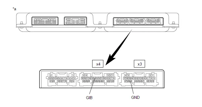
| *a | Component without harness connected (Battery ECU Assembly) | - | - |
Standard Resistance:
 Click Location & Routing(x3,x4) Click Connector(x3) Click Connector(x4)
 | Tester Connection | Condition | Specified Condition |
|---|---|---|
| x3-25 (GND) - x4-14 (GIB) | Ignition switch off | Below 1 Ω |
Post-procedure1
(c) Install the battery ECU assembly.
| NG |

| REPLACE BATTERY ECU ASSEMBLY |
|

| 6. | CHECK BATTERY ECU ASSEMBLY (BATTERY CURRENT SENSOR OUTPUT VOLTAGE (IB1)) |
CAUTION:
Be sure to wear insulated gloves and protective goggles.
Pre-procedure1
(a) Check that the service plug grip is not installed.
NOTICE:
After removing the service plug grip, do not turn the ignition switch to ON (READY), unless instructed by the repair manual because this may cause a malfunction.
(b) Connect the SST.
HINT:
Click here

(c) Connect the cable to the negative (-) auxiliary battery terminal.
(d) Turn the ignition switch to ON.
Procedure1
| (e) Measure the voltage according to the value(s) in the table below. Standard Voltage:  Click Location & Routing(x4) Click Connector(x4) Click Location & Routing(x4) Click Connector(x4)
NOTICE: Turning the ignition switch to ON with the service plug grip removed causes other DTCs to be stored. Clear the DTCs after performing this inspection. Result:
|
|

Post-procedure1
(f) Turn the ignition switch off.
(g) Disconnect the cable from the negative (-) auxiliary battery terminal.
(h) Disconnect the SST.
| NG |

| GO TO STEP 15 |
|

| 7. | CHECK BATTERY ECU ASSEMBLY (BATTERY CURRENT SENSOR OUTPUT VOLTAGE (IB0)) |
CAUTION:
Be sure to wear insulated gloves and protective goggles.
Pre-procedure1
(a) Check that the service plug grip is not installed.
NOTICE:
After removing the service plug grip, do not turn the ignition switch to ON (READY), unless instructed by the repair manual because this may cause a malfunction.
(b) Connect the SST.
HINT:
Click here

(c) Connect the cable to the negative (-) auxiliary battery terminal.
(d) Turn the ignition switch to ON.
Procedure1
| (e) Measure the voltage according to the value(s) in the table below. Standard Voltage:  Click Location & Routing(x4) Click Connector(x4) Click Location & Routing(x4) Click Connector(x4)
NOTICE: Turning the ignition switch to ON with the service plug grip removed causes other DTCs to be stored. Clear the DTCs after performing this inspection. Result:
|
|

Post-procedure1
(f) Turn the ignition switch off.
(g) Disconnect the cable from the negative (-) auxiliary battery terminal.
(h) Disconnect the SST.
| NG |

| GO TO STEP 12 |
|

| 8. | CHECK BATTERY ECU ASSEMBLY (BATTERY CURRENT SENSOR OUTPUT VOLTAGE (IBL)) |
CAUTION:
Be sure to wear insulated gloves and protective goggles.
Pre-procedure1
(a) Check that the service plug grip is not installed.
NOTICE:
After removing the service plug grip, do not turn the ignition switch to ON (READY), unless instructed by the repair manual because this may cause a malfunction.
(b) Connect the SST.
HINT:
Click here

(c) Connect the cable to the negative (-) auxiliary battery terminal.
(d) Turn the ignition switch to ON.
Procedure1
| (e) Measure the voltage according to the value(s) in the table below. Standard Voltage:  Click Location & Routing(x4) Click Connector(x4) Click Location & Routing(x4) Click Connector(x4)
NOTICE: Turning the ignition switch to ON with the service plug grip removed causes other DTCs to be stored. Clear the DTCs after performing this inspection. Result:
|
|

Post-procedure1
(f) Turn the ignition switch off.
(g) Disconnect the cable from the negative (-) auxiliary battery terminal.
(h) Disconnect the SST.
| OK |

| REPLACE BATTERY ECU ASSEMBLY |
|

| 9. | CHECK BATTERY ECU ASSEMBLY (BATTERY CURRENT SENSOR OUTPUT VOLTAGE (IBL)) |
CAUTION:
Be sure to wear insulated gloves and protective goggles.
Pre-procedure1
(a) Check that the service plug grip is not installed.
NOTICE:
After removing the service plug grip, do not turn the ignition switch to ON (READY), unless instructed by the repair manual because this may cause a malfunction.
(b) Connect the SST.
HINT:
Click here

(c) Connect the cable to the negative (-) auxiliary battery terminal.
(d) Turn the ignition switch to ON.
Procedure1
| (e) Measure the voltage according to the value(s) in the table below.  Click Location & Routing(x4) Click Connector(x4) Click Location & Routing(x4) Click Connector(x4)
NOTICE: Turning the ignition switch to ON with the service plug grip removed causes other DTCs to be stored. Clear the DTCs after performing this inspection. Result:
|
|

Post-procedure1
(f) Turn the ignition switch off.
(g) Disconnect the cable from the negative (-) auxiliary battery terminal.
(h) Disconnect the SST.
| A |

| REPLACE NO. 1 TRACTION BATTERY DEVICE BOX ASSEMBLY |
| C |

| GO TO STEP 11 |
|

| 10. | CHECK BATTERY ECU ASSEMBLY (BATTERY CURRENT SENSOR OUTPUT VOLTAGE (IBL)) |
CAUTION:
Be sure to wear insulated gloves and protective goggles.
Pre-procedure1
(a) Check that the service plug grip is not installed.
NOTICE:
After removing the service plug grip, do not turn the ignition switch to ON (READY), unless instructed by the repair manual because this may cause a malfunction.
(b) Connect the SST.
HINT:
Click here

| (c) Disconnect the No. 1 traction battery device box assembly connector. NOTICE: Before disconnecting the connector, check that it is not loose or disconnected. |
|

(d) Connect the cable to the negative (-) auxiliary battery terminal.
(e) Turn the ignition switch to ON.
Procedure1
| (f) Measure the voltage according to the value(s) in the table below. Standard Voltage:  Click Location & Routing(x4) Click Connector(x4) Click Location & Routing(x4) Click Connector(x4)
NOTICE:
Result:
|
|
Post-procedure1
(g) Turn the ignition switch off.
(h) Disconnect the cable from the negative (-) auxiliary battery terminal.
(i) Reconnect the No. 1 traction battery device box assembly connector.
(j) Disconnect the SST.
| OK |

| REPLACE NO. 1 TRACTION BATTERY DEVICE BOX ASSEMBLY |
| NG |

| REPLACE BATTERY ECU ASSEMBLY |
| 11. | CHECK BATTERY ECU ASSEMBLY (VIB - IBL) |
CAUTION:
Be sure to wear insulated gloves and protective goggles.
Pre-procedure1
(a) Check that the service plug grip is not installed.
NOTICE:
After removing the service plug grip, do not turn the ignition switch to ON (READY), unless instructed by the repair manual because this may cause a malfunction.
| (b) Disconnect the No. 1 traction battery device box assembly connector. NOTICE: Before disconnecting the connector, check that it is not loose or disconnected. |
|

(c) Reconnect the battery ECU assembly connector.
Procedure1
(d) Measure the resistance according to the value(s) in the tables below.
Standard Resistance:
 Click Location & Routing(x11) Click Connector(x11)
 | Tester Connection | Condition | Specified Condition |
|---|---|---|
| x11-2 (VIB) - x11-1 (IBL) | Ignition switch off | 10 kΩ or higher |
Post-procedure1
(e) Reconnect the No. 1 traction battery device box assembly connector.
| OK |

| REPLACE NO. 1 TRACTION BATTERY DEVICE BOX ASSEMBLY |
| NG |

| REPLACE BATTERY ECU ASSEMBLY |
| 12. | CHECK BATTERY ECU ASSEMBLY (BATTERY CURRENT SENSOR OUTPUT VOLTAGE (IB0)) |
CAUTION:
Be sure to wear insulated gloves and protective goggles.
Pre-procedure1
(a) Check that the service plug grip is not installed.
NOTICE:
After removing the service plug grip, do not turn the ignition switch to ON (READY), unless instructed by the repair manual because this may cause a malfunction.
(b) Connect the SST.
HINT:
Click here

(c) Connect the cable to the negative (-) auxiliary battery terminal.
(d) Turn the ignition switch to ON.
Procedure1
| (e) Measure the voltage according to the value(s) in the table below.  Click Location & Routing(x4) Click Connector(x4) Click Location & Routing(x4) Click Connector(x4)
NOTICE: Turning the ignition switch to ON with the service plug grip removed causes other DTCs to be stored. Clear the DTCs after performing this inspection. Result:
|
|

Post-procedure1
(f) Turn the ignition switch off.
(g) Disconnect the cable from the negative (-) auxiliary battery terminal.
(h) Disconnect the SST.
| A |

| REPLACE NO. 1 TRACTION BATTERY DEVICE BOX ASSEMBLY |
| C |

| GO TO STEP 14 |
|

| 13. | CHECK BATTERY ECU ASSEMBLY (BATTERY CURRENT SENSOR OUTPUT VOLTAGE (IB0)) |
CAUTION:
Be sure to wear insulated gloves and protective goggles.
Pre-procedure1
(a) Check that the service plug grip is not installed.
NOTICE:
After removing the service plug grip, do not turn the ignition switch to ON (READY), unless instructed by the repair manual because this may cause a malfunction.
(b) Connect the SST.
HINT:
Click here

| (c) Disconnect the No. 1 traction battery device box assembly connector. NOTICE: Before disconnecting the connector, check that it is not loose or disconnected. |
|

(d) Connect the cable to the negative (-) auxiliary battery terminal.
(e) Turn the ignition switch to ON.
Procedure1
| (f) Measure the voltage according to the value(s) in the table below. Standard Voltage:  Click Location & Routing(x4) Click Connector(x4) Click Location & Routing(x4) Click Connector(x4)
NOTICE:
Result:
|
|

Post-procedure1
(g) Turn the ignition switch off.
(h) Disconnect the cable from the negative (-) auxiliary battery terminal.
(i) Reconnect the No. 1 traction battery device box assembly connector.
(j) Disconnect the SST.
| OK |

| REPLACE NO. 1 TRACTION BATTERY DEVICE BOX ASSEMBLY |
| NG |

| REPLACE BATTERY ECU ASSEMBLY |
| 14. | CHECK BATTERY ECU ASSEMBLY (VIB - IB0) |
CAUTION:
Be sure to wear insulated gloves and protective goggles.
Pre-procedure1
(a) Check that the service plug grip is not installed.
NOTICE:
After removing the service plug grip, do not turn the ignition switch to ON (READY), unless instructed by the repair manual because this may cause a malfunction.
| (b) Disconnect the No. 1 traction battery device box assembly connector. NOTICE: Before disconnecting the connector, check that it is not loose or disconnected. |
|

(c) Reconnect the battery ECU assembly connector.
Procedure1
(d) Measure the resistance according to the value(s) in the tables below.
Standard Resistance:
 Click Location & Routing(x11) Click Connector(x11)
 | Tester Connection | Condition | Specified Condition |
|---|---|---|
| x11-2 (VIB) - x11-3 (IB0) | Ignition switch off | 10 kΩ or higher |
Post-procedure1
(e) Reconnect the No. 1 traction battery device box assembly connector.
| OK |

| REPLACE NO. 1 TRACTION BATTERY DEVICE BOX ASSEMBLY |
| NG |

| REPLACE BATTERY ECU ASSEMBLY |
| 15. | CHECK BATTERY ECU ASSEMBLY (BATTERY CURRENT SENSOR OUTPUT VOLTAGE (IB1)) |
CAUTION:
Be sure to wear insulated gloves and protective goggles.
Pre-procedure1
(a) Check that the service plug grip is not installed.
NOTICE:
After removing the service plug grip, do not turn the ignition switch to ON (READY), unless instructed by the repair manual because this may cause a malfunction.
(b) Connect the SST.
HINT:
Click here

(c) Connect the cable to the negative (-) auxiliary battery terminal.
(d) Turn the ignition switch to ON.
Procedure1
| (e) Measure the voltage according to the value(s) in the table below.  Click Location & Routing(x4) Click Connector(x4) Click Location & Routing(x4) Click Connector(x4)
NOTICE: Turning the ignition switch to ON with the service plug grip removed causes other DTCs to be stored. Clear the DTCs after performing this inspection. Result:
|
|

Post-procedure1
(f) Turn the ignition switch off.
(g) Disconnect the cable from the negative (-) auxiliary battery terminal.
(h) Disconnect the SST.
| A |

| REPLACE NO. 1 TRACTION BATTERY DEVICE BOX ASSEMBLY |
| C |

| GO TO STEP 18 |
|

| 16. | CHECK BATTERY ECU ASSEMBLY (BATTERY CURRENT SENSOR OUTPUT VOLTAGE (IB1)) |
CAUTION:
Be sure to wear insulated gloves and protective goggles.
Pre-procedure1
(a) Check that the service plug grip is not installed.
NOTICE:
After removing the service plug grip, do not turn the ignition switch to ON (READY), unless instructed by the repair manual because this may cause a malfunction.
(b) Connect the SST.
HINT:
Click here

| (c) Disconnect the No. 1 traction battery device box assembly connector. NOTICE: Before disconnecting the connector, check that it is not loose or disconnected. |
|

(d) Connect the cable to the negative (-) auxiliary battery terminal.
(e) Turn the ignition switch to ON.
Procedure1
| (f) Measure the voltage according to the value(s) in the table below. Standard Voltage:  Click Location & Routing(x4) Click Connector(x4) Click Location & Routing(x4) Click Connector(x4)
NOTICE:
Result:
|
|

Post-procedure1
(g) Turn the ignition switch off.
(h) Disconnect the cable from the negative (-) auxiliary battery terminal.
(i) Reconnect the No. 1 traction battery device box assembly connector.
(j) Disconnect the SST.
| OK |

| REPLACE NO. 1 TRACTION BATTERY DEVICE BOX ASSEMBLY |
| NG |

| REPLACE BATTERY ECU ASSEMBLY |
| 17. | CHECK BATTERY ECU ASSEMBLY (VIB VOLTAGE) |
CAUTION:
Be sure to wear insulated gloves and protective goggles.
Pre-procedure1
(a) Check that the service plug grip is not installed.
NOTICE:
After removing the service plug grip, do not turn the ignition switch to ON (READY), unless instructed by the repair manual because this may cause a malfunction.
(b) Connect the SST.
HINT:
Click here

| (c) Disconnect the No. 1 traction battery device box assembly connector. NOTICE: Before disconnecting the connector, check that it is not loose or disconnected. |
|

(d) Connect the cable to the negative (-) auxiliary battery terminal.
(e) Turn the ignition switch to ON.
Procedure1
| (f) Measure the voltage according to the value(s) in the table below. Standard Voltage:  Click Location & Routing(x4) Click Connector(x4) Click Location & Routing(x4) Click Connector(x4)
NOTICE:
Result:
|
|

Post-procedure1
(g) Turn the ignition switch off.
(h) Disconnect the cable from the negative (-) auxiliary battery terminal.
(i) Reconnect the No. 1 traction battery device box assembly connector.
(j) Disconnect the SST.
| OK |

| REPLACE NO. 1 TRACTION BATTERY DEVICE BOX ASSEMBLY |
| NG |

| REPLACE BATTERY ECU ASSEMBLY |
| 18. | CHECK BATTERY ECU ASSEMBLY (VIB - IB1) |
CAUTION:
Be sure to wear insulated gloves and protective goggles.
Pre-procedure1
(a) Check that the service plug grip is not installed.
NOTICE:
After removing the service plug grip, do not turn the ignition switch to ON (READY), unless instructed by the repair manual because this may cause a malfunction.
| (b) Disconnect the No. 1 traction battery device box assembly connector. NOTICE: Before disconnecting the connector, check that it is not loose or disconnected. |
|
(c) Reconnect the battery ECU assembly connector.
Procedure1
(d) Measure the resistance according to the value(s) in the tables below.
Standard Resistance:
 Click Location & Routing(x11) Click Connector(x11)
 | Tester Connection | Condition | Specified Condition |
|---|---|---|
| x11-2 (VIB) - x11-5 (IB1) | Ignition switch off | 10 kΩ or higher |
Post-procedure1
(e) Reconnect the No. 1 traction battery device box assembly connector.
| OK |

| REPLACE NO. 1 TRACTION BATTERY DEVICE BOX ASSEMBLY |
| NG |

| REPLACE BATTERY ECU ASSEMBLY |
Hybrid/EV Battery Current Sensor "A" Signal Bias Level Out of Range / Zero Adjustment Failure (P0ABF28)
DESCRIPTION
Refer to the description for DTC P0ABF11.
Click here

| DTC No. | Detection Item | DTC Detection Condition | Trouble Area | MIL | Warning Indicate | DTC Output from | Priority | Note |
|---|---|---|---|---|---|---|---|---|
| P0ABF28 | Hybrid/EV Battery Current Sensor "A" Signal Bias Level Out of Range / Zero Adjustment Failure | The offset value of the battery current sensor is excessively large. (1 trip detection logic) |
| Comes on | Master Warning: Comes on | HV Battery | A | SAE Code: P0AC0 |
When the ignition switch is ON, normally the HV battery current does not flow. If the HV battery current value is above the specification, this DTC will be stored.
HINT:
-
Make sure to perform Current Sensor Offset Learning after replacing a battery current sensor.
Click here

- This DTC may be output if Current Sensor Offset Learning has not been completed.
MONITOR DESCRIPTION
If the battery ECU assembly detects a malfunction in a battery current sensor, the battery ECU assembly will illuminate the MIL and store a DTC.
MONITOR STRATEGY
| Related DTCs | P0AC0 (INF P0ABF28): Current sensor malfunction |
| Required sensors/components | Battery current sensor |
| Frequency of operation | Continuous |
| Duration | TMC's intellectual property |
| MIL operation | 1 driving cycle |
| Sequence of operation | None |
TYPICAL ENABLING CONDITIONS
| The monitor will run whenever the following DTCs are not stored | TMC's intellectual property |
| Other conditions belong to TMC's intellectual property | - |
TYPICAL MALFUNCTION THRESHOLDS
| TMC's intellectual property | - |
COMPONENT OPERATING RANGE
| Battery ECU assembly | DTC P0AC0 (INF P0ABF28) is not detected |
CONFIRMATION DRIVING PATTERN
HINT:
-
After repair has been completed, clear the DTC and then check that the Toyota Prius vehicle has returned to normal by performing the following All Readiness check procedure.
Click here

-
When clearing the permanent DTCs, refer to the "CLEAR PERMANENT DTC" procedure.
Click here

- Clear the DTCs (even if no DTCs are stored, perform the clear DTC procedure).
- Turn the ignition switch off and wait for 2 minutes or more.
- Drive the Toyota Prius vehicle on urban roads for approximately 10 minutes.[*1]
- Turn the ignition switch off and wait for 2 minutes or more.[*2]
-
Turn the ignition switch to ON and wait for 10 seconds or more.[*3]
HINT:
[*1] to [*3]: Normal judgment procedure.
The normal judgment procedure is used to complete DTC judgment and also used when clearing permanent DTCs.
- Enter the following menus: Powertrain / HV Battery / Utility / All Readiness.
-
Check the DTC judgment result.
HINT:
- If the judgment result shows NORMAL, the system is normal.
- If the judgment result shows ABNORMAL, the system has a malfunction.
- If the judgment result shows INCOMPLETE or N/A, perform the normal judgment procedure again.
WIRING DIAGRAM
Refer to the wiring diagram for DTC P0ABF11.
Click here

CAUTION / NOTICE / HINT
CAUTION:
Refer to the precautions before inspecting high voltage circuit.
Click here

NOTICE:
-
After the ignition switch is turned off, there may be a waiting time before disconnecting the auxiliary negative (-) battery terminal.
Click here

-
When disconnecting and reconnecting the auxiliary battery.
HINT:
When disconnecting and reconnecting the auxiliary battery, there is an automatic learning function that completes learning when the respective system is used.
Click here

PROCEDURE
| 1. | CHECK DTC OUTPUT (HV BATTERY, HYBRID CONTROL) |
Pre-procedure1
(a) None
Procedure1
(b) Check for DTCs.
Powertrain > HV Battery > Trouble Codes Powertrain > Hybrid Control > Trouble Codes| Result | Proceed to |
|---|---|
| "P0ABF28" only is output, or DTCs except the ones in the table below are also output. | A |
| DTCs of hybrid battery system in the table below are output. | B |
| DTCs of hybrid control system in the table below are output. | C |
| System | Relevant DTC | |
|---|---|---|
| Hybrid battery system | P060A47 | Hybrid/EV Battery Energy Control Module Monitoring Processor Watchdog / Safety MCU Failure |
| P060B49 | Hybrid/EV Battery Energy Control Module A/D Processing Internal Electronic Failure | |
| P060687 | Hybrid/EV Battery Energy Control Module Processor to Monitoring Processor Missing Message | |
| P062F46 | Hybrid/EV Battery Energy Control Module EEPROM Calibration / Parameter Memory Failure | |
| Hybrid control system | P0A1F94 | Hybrid/EV Battery Energy Control Module Unexpected Operation |
Post-procedure1
(c) Turn the ignition switch off.
| B |

| GO TO DTC CHART (HYBRID BATTERY SYSTEM) |
| C |

| GO TO DTC CHART (HYBRID CONTROL SYSTEM) |
|

| 2. | CHECK HARNESS AND CONNECTOR (BATTERY ECU ASSEMBLY - NO. 1 TRACTION BATTERY DEVICE BOX ASSEMBLY) |
Click here

| NG |

| REPAIR OR REPLACE HARNESS OR CONNECTOR |
|

| 3. | CHECK NO. 1 TRACTION BATTERY DEVICE BOX ASSEMBLY (BATTERY CURRENT SENSOR (IB0)) |
CAUTION:
Be sure to wear insulated gloves and protective goggles.
Pre-procedure1
(a) Check that the service plug grip is not installed.
NOTICE:
After removing the service plug grip, do not turn the ignition switch to ON (READY), unless instructed by the repair manual because this may cause a malfunction.
(b) Connect the SST.
HINT:
Click here

(c) Connect the cable to the negative (-) auxiliary battery terminal.
(d) Turn the ignition switch to ON.
Procedure1
| (e) Using a Toyota electrical tester set to 40 V, measure the VIB voltage according to the value(s) in the table below.  Click Location & Routing(x4) Click Connector(x4) Click Location & Routing(x4) Click Connector(x4)
NOTICE:
|
|

Procedure2
| (f) Using a Toyota electrical tester set to 4 V, measure the IB0 voltage according to the value(s) in the table below.  Click Location & Routing(x4) Click Connector(x4) Click Location & Routing(x4) Click Connector(x4)
NOTICE: Be sure to set the Toyota electrical tester to 4 V when performing this test. |
|
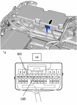
Procedure3
(g) Compare the measured values of the IB0 terminal voltage and VIB terminal voltage using the following formula:
| IB0 voltage - 0.34 X VIB voltage = less than 0.05 V |
| IB0 voltage - 0.34 X VIB voltage = -0.05 V or higher |
| Result | Proceed to |
|---|---|
| Within the specified range above | A |
| Other than above | B |
Post-procedure1
(h) Turn the ignition switch off.
(i) Disconnect the cable from the negative (-) auxiliary battery terminal.
(j) Disconnect the SST.
| B |

| REPLACE NO. 1 TRACTION BATTERY DEVICE BOX ASSEMBLY |
|

| 4. | CHECK NO. 1 TRACTION BATTERY DEVICE BOX ASSEMBLY (BATTERY CURRENT SENSOR (IB1)) |
CAUTION:
Be sure to wear insulated gloves and protective goggles.
Pre-procedure1
(a) Check that the service plug grip is not installed.
NOTICE:
After removing the service plug grip, do not turn the ignition switch to ON (READY), unless instructed by the repair manual because this may cause a malfunction.
(b) Connect the SST.
HINT:
Click here

(c) Connect the cable to the negative (-) auxiliary battery terminal.
(d) Turn the ignition switch to ON.
Procedure1
| (e) Using a Toyota electrical tester set to 40 V, measure the VIB voltage according to the value(s) in the table below.  Click Location & Routing(x4) Click Connector(x4) Click Location & Routing(x4) Click Connector(x4)
NOTICE:
|
|

Procedure2
| (f) Using a Toyota electrical tester set to 4 V, measure the IB1 voltage according to the value(s) in the table below.  Click Location & Routing(x4) Click Connector(x4) Click Location & Routing(x4) Click Connector(x4)
NOTICE: Be sure to set the Toyota electrical tester to 4 V when performing this test. |
|

Procedure3
(g) Compare the measured values of the IB1 terminal voltage and VIB terminal voltage using the following formula:
| Condition |
|---|
| IB1 voltage - 0.66 X VIB voltage = less than 0.05 V |
| IB1 voltage - 0.66 X VIB voltage = -0.05 V or higher |
| Result | Proceed to |
|---|---|
| Within the specified range above | A |
| Other than above | B |
Post-procedure1
(h) Turn the ignition switch off.
(i) Disconnect the cable from the negative (-) auxiliary battery terminal.
(j) Disconnect the SST.
| B |

| REPLACE NO. 1 TRACTION BATTERY DEVICE BOX ASSEMBLY |
|

| 5. | REPLACE BATTERY ECU ASSEMBLY |
HINT:
Click here

|

| 6. | SIMULATION TEST |
Pre-procedure1
(a) None
Procedure1
(b) Clear the DTCs and freeze frame data.
Powertrain > HV Battery > Clear DTCsPost-procedure1
(c) Drive the Toyota Prius vehicle on urban roads for approximately 10 minutes.
(d) Turn the ignition switch off and wait for 2 minutes or more.
(e) Turn the ignition switch to ON and wait for 10 seconds or more.
|

| 7. | CHECK DTC OUTPUT (HV BATTERY) |
Pre-procedure1
(a) None
Procedure1
(b) Check for DTCs.
Powertrain > HV Battery > Trouble Codes| Result | Proceed to |
|---|---|
| DTCs are not output. | A |
| P0ABF28 is also output. | B |
Post-procedure1
(c) Turn the ignition switch off.
| A |

| END |
| B |

| REPLACE NO. 1 TRACTION BATTERY DEVICE BOX ASSEMBLY |
Hybrid/EV Battery Current Sensor "A" Signal Stuck In Range (P0ABF2A)
DESCRIPTION
Refer to the description for DTC P0ABF11.
Click here

| DTC No. | Detection Item | DTC Detection Condition | Trouble Area | MIL | Warning Indicate | DTC Output from | Priority | Note |
|---|---|---|---|---|---|---|---|---|
| P0ABF2A | Hybrid/EV Battery Current Sensor "A" Signal Stuck In Range | The hybrid battery voltage is changing but the hybrid battery current sensor output does not change. (1 trip detection logic) |
| Comes on | Master Warning: Comes on | HV Battery | A | SAE Code: P0AC0 |
MONITOR DESCRIPTION
If the battery ECU assembly detects a malfunction in a battery current sensor, the battery ECU assembly will illuminate the MIL and store a DTC.
MONITOR STRATEGY
| Related DTCs | P0AC0 (INF P0ABF2A): Current sensor malfunction |
| Required sensors/components | Battery current sensor |
| Frequency of operation | Continuous |
| Duration | TMC's intellectual property |
| MIL operation | 1 driving cycle |
| Sequence of operation | None |
TYPICAL ENABLING CONDITIONS
| The monitor will run whenever the following DTCs are not stored | TMC's intellectual property |
| Other conditions belong to TMC's intellectual property | - |
TYPICAL MALFUNCTION THRESHOLDS
| TMC's intellectual property | - |
COMPONENT OPERATING RANGE
| Battery ECU assembly | DTC P0AC0 (INF P0ABF2A) is not detected |
CONFIRMATION DRIVING PATTERN
HINT:
-
After repair has been completed, clear the DTC and then check that the Toyota Prius vehicle has returned to normal by performing the following All Readiness check procedure.
Click here

-
When clearing the permanent DTCs, refer to the "CLEAR PERMANENT DTC" procedure.
Click here

- Clear the DTCs (even if no DTCs are stored, perform the clear DTC procedure).
- Turn the ignition switch off and wait for 2 minutes or more.
-
Drive the Toyota Prius vehicle on urban roads for approximately 10 minutes.[*1]
HINT:
[*1]: Normal judgment procedure.
The normal judgment procedure is used to complete DTC judgment and also used when clearing permanent DTCs.
- Enter the following menus: Powertrain / HV Battery / Utility / All Readiness.
-
Check the DTC judgment result.
HINT:
- If the judgment result shows NORMAL, the system is normal.
- If the judgment result shows ABNORMAL, the system has a malfunction.
- If the judgment result shows INCOMPLETE or N/A, perform the normal judgment procedure again.
PROCEDURE
| 1. | CHECK DTC OUTPUT (HV BATTERY, HYBRID CONTROL) |
Pre-procedure1
(a) None
Procedure1
(b) Check for DTCs.
Powertrain > HV Battery > Trouble Codes Powertrain > Hybrid Control > Trouble Codes| Result | Proceed to |
|---|---|
| "P0ABF2A" only is output, or DTCs except the ones in the table below are also output. | A |
| DTCs of hybrid battery system in the table below are output. | B |
| DTCs of hybrid control system in the table below are output. | C |
| System | Relevant DTC | |
|---|---|---|
| Hybrid battery system | P060A47 | Hybrid/EV Battery Energy Control Module Monitoring Processor Watchdog / Safety MCU Failure |
| P060B49 | Hybrid/EV Battery Energy Control Module A/D Processing Internal Electronic Failure | |
| P060687 | Hybrid/EV Battery Energy Control Module Processor to Monitoring Processor Missing Message | |
| P0ABF11 | Hybrid/EV Battery Current Sensor "A" Circuit Short to Ground | |
| P0ABF15 | Hybrid/EV Battery Current Sensor "A" Circuit Short to Auxiliary Battery or Open | |
| P0B0E11 | Hybrid/EV Battery Current Sensor "B" Circuit Short to Ground | |
| P0B0E15 | Hybrid/EV Battery Current Sensor "B" Circuit Short to Auxiliary Battery or Open | |
| P1CBB12 | Hybrid/EV Battery Current Sensor Power Supply Circuit Short to Auxiliary Battery | |
| P1CBB14 | Hybrid/EV Battery Current Sensor Power Supply Circuit Short to Ground or Open | |
| P2BE411 | Hybrid/EV Battery Pack Current Sensor "C" Low Circuit Short to Ground | |
| P2BE415 | Hybrid/EV Battery Pack Current Sensor "C" High Circuit Short to Auxiliary Battery or Open | |
| Hybrid control system | P0A1F94 | Hybrid/EV Battery Energy Control Module Unexpected Operation |
Post-procedure1
(c) Turn the ignition switch off.
| B |

| GO TO DTC CHART (HYBRID BATTERY SYSTEM) |
| C |

| GO TO DTC CHART (HYBRID CONTROL SYSTEM) |
|

| 2. | CHECK DTC OUTPUT (HV BATTERY) |
Pre-procedure1
(a) None
Procedure1
(b) Check for DTCs.
Powertrain > HV Battery > Trouble Codes| Result | Proceed to |
|---|---|
| "P1A001C, P1A051C, P1A0A1C or P301A1C" is not output. | A |
| "P1A001C, P1A051C, P1A0A1C or P301A1C" is also output. | B |
Post-procedure1
(c) Turn the ignition switch off.
| B |

| GO TO DTC CHART (HYBRID BATTERY SYSTEM) |
|

| 3. | READ VALUE USING GTS |
Pre-procedure1
(a) Turn the ignition switch to ON.
NOTICE:
Do not turn the ignition switch to ON (READY).
Procedure1
(b) Check the voltage of each "Hybrid/EV Battery Cell Voltage" of "Hybrid/EV Battery Cell 1 to 72 Voltage" in the Data List with the ignition switch ON.
NOTICE:
Select "Hybrid/EV Battery Cell 1 to 72 Voltage" only. (Do not select any other Data List items.)
Powertrain > HV Battery > Data List| Tester Display |
|---|
| Hybrid/EV Battery Cell 1 Voltage |
| Hybrid/EV Battery Cell 2 Voltage |
| Hybrid/EV Battery Cell 3 Voltage |
| Hybrid/EV Battery Cell 4 Voltage |
| Hybrid/EV Battery Cell 5 Voltage |
| Hybrid/EV Battery Cell 6 Voltage |
| Hybrid/EV Battery Cell 7 Voltage |
| Hybrid/EV Battery Cell 8 Voltage |
| Hybrid/EV Battery Cell 9 Voltage |
| Hybrid/EV Battery Cell 10 Voltage |
| Hybrid/EV Battery Cell 11 Voltage |
| Hybrid/EV Battery Cell 12 Voltage |
| Hybrid/EV Battery Cell 13 Voltage |
| Hybrid/EV Battery Cell 14 Voltage |
| Hybrid/EV Battery Cell 15 Voltage |
| Hybrid/EV Battery Cell 16 Voltage |
| Hybrid/EV Battery Cell 17 Voltage |
| Hybrid/EV Battery Cell 18 Voltage |
| Hybrid/EV Battery Cell 19 Voltage |
| Hybrid/EV Battery Cell 20 Voltage |
| Hybrid/EV Battery Cell 21 Voltage |
| Hybrid/EV Battery Cell 22 Voltage |
| Hybrid/EV Battery Cell 23 Voltage |
| Hybrid/EV Battery Cell 24 Voltage |
| Hybrid/EV Battery Cell 25 Voltage |
| Hybrid/EV Battery Cell 26 Voltage |
| Hybrid/EV Battery Cell 27 Voltage |
| Hybrid/EV Battery Cell 28 Voltage |
| Hybrid/EV Battery Cell 29 Voltage |
| Hybrid/EV Battery Cell 30 Voltage |
| Hybrid/EV Battery Cell 31 Voltage |
| Hybrid/EV Battery Cell 32 Voltage |
| Hybrid/EV Battery Cell 33 Voltage |
| Hybrid/EV Battery Cell 34 Voltage |
| Hybrid/EV Battery Cell 35 Voltage |
| Hybrid/EV Battery Cell 36 Voltage |
| Hybrid/EV Battery Cell 37 Voltage |
| Hybrid/EV Battery Cell 38 Voltage |
| Hybrid/EV Battery Cell 39 Voltage |
| Hybrid/EV Battery Cell 40 Voltage |
| Hybrid/EV Battery Cell 41 Voltage |
| Hybrid/EV Battery Cell 42 Voltage |
| Hybrid/EV Battery Cell 43 Voltage |
| Hybrid/EV Battery Cell 44 Voltage |
| Hybrid/EV Battery Cell 45 Voltage |
| Hybrid/EV Battery Cell 46 Voltage |
| Hybrid/EV Battery Cell 47 Voltage |
| Hybrid/EV Battery Cell 48 Voltage |
| Hybrid/EV Battery Cell 49 Voltage |
| Hybrid/EV Battery Cell 50 Voltage |
| Hybrid/EV Battery Cell 51 Voltage |
| Hybrid/EV Battery Cell 52 Voltage |
| Hybrid/EV Battery Cell 53 Voltage |
| Hybrid/EV Battery Cell 54 Voltage |
| Hybrid/EV Battery Cell 55 Voltage |
| Hybrid/EV Battery Cell 56 Voltage |
| Hybrid/EV Battery Cell 57 Voltage |
| Hybrid/EV Battery Cell 58 Voltage |
| Hybrid/EV Battery Cell 59 Voltage |
| Hybrid/EV Battery Cell 60 Voltage |
| Hybrid/EV Battery Cell 61 Voltage |
| Hybrid/EV Battery Cell 62 Voltage |
| Hybrid/EV Battery Cell 63 Voltage |
| Hybrid/EV Battery Cell 64 Voltage |
| Hybrid/EV Battery Cell 65 Voltage |
| Hybrid/EV Battery Cell 66 Voltage |
| Hybrid/EV Battery Cell 67 Voltage |
| Hybrid/EV Battery Cell 68 Voltage |
| Hybrid/EV Battery Cell 69 Voltage |
| Hybrid/EV Battery Cell 70 Voltage |
| Hybrid/EV Battery Cell 71 Voltage |
| Hybrid/EV Battery Cell 72 Voltage |
Specified Condition:
Any "Hybrid/EV Battery Cell Voltage" changes by 0.05 V or more, 60 seconds after the ignition switch is turned to ON. (The difference between the maximum and minimum voltage is 0.05 V or more.)
| Result | Proceed to |
|---|---|
| The change in voltage of any "Hybrid/EV Battery Cell Voltage" is 0.05 V or more. | A |
| Other than above | B |
Post-procedure1
(c) Turn the ignition switch off.
| A |

| REPLACE BATTERY ECU ASSEMBLY |
| B |

| REPLACE NO. 1 TRACTION BATTERY DEVICE BOX ASSEMBLY |
Hybrid/EV Battery Current Sensor "A"/"B" Signal Compare Failure (P0B1362)
DESCRIPTION
Refer to the description for DTC P0ABF11.
Click here

| DTC No. | Detection Item | DTC Detection Condition | Trouble Area | MIL | Warning Indicate | DTC Output from | Priority | Note |
|---|---|---|---|---|---|---|---|---|
| P0B1362 | Hybrid/EV Battery Current Sensor "A"/"B" Signal Compare Failure | A battery current sensor is malfunctioning.*1 (1 trip detection logic) |
| Comes on | Master Warning: Comes on | HV Battery | A | SAE Code: P0B13 |
*1: The difference in output of the main and sub battery current sensors is large.
MONITOR DESCRIPTION
If the battery ECU assembly detects a malfunction in a battery current sensor, the battery ECU assembly will illuminate the MIL and store a DTC.
MONITOR STRATEGY
| Related DTCs | P0B13 (INF P0B1362): Current sensor malfunction |
| Required sensors/components | Battery current sensor |
| Frequency of operation | Continuous |
| Duration | TMC's intellectual property |
| MIL operation | 1 driving cycle |
| Sequence of operation | None |
TYPICAL ENABLING CONDITIONS
| The monitor will run whenever the following DTCs are not stored | TMC's intellectual property |
| Other conditions belong to TMC's intellectual property | - |
TYPICAL MALFUNCTION THRESHOLDS
| TMC's intellectual property | - |
COMPONENT OPERATING RANGE
| Battery ECU assembly | DTC P0B13 (INF P0B1362) is not detected |
CONFIRMATION DRIVING PATTERN
HINT:
-
After repair has been completed, clear the DTC and then check that the Toyota Prius vehicle has returned to normal by performing the following All Readiness check procedure.
Click here

-
When clearing the permanent DTCs, refer to the "CLEAR PERMANENT DTC" procedure.
Click here

- Clear the DTCs (even if no DTCs are stored, perform the clear DTC procedure).
- Turn the ignition switch off and wait for 2 minutes or more.
-
Drive the Toyota Prius vehicle on urban roads for approximately 10 minutes.[*1]
HINT:
[*1]: Normal judgment procedure.
The normal judgment procedure is used to complete DTC judgment and also used when clearing permanent DTCs.
- Enter the following menus: Powertrain / HV Battery / Utility / All Readiness.
-
Check the DTC judgment result.
HINT:
- If the judgment result shows NORMAL, the system is normal.
- If the judgment result shows ABNORMAL, the system has a malfunction.
- If the judgment result shows INCOMPLETE or N/A, perform the normal judgment procedure again.
CAUTION / NOTICE / HINT
CAUTION:
Refer to the precautions before inspecting high voltage circuit.
Click here

NOTICE:
-
After the ignition switch is turned off, there may be a waiting time before disconnecting the auxiliary negative (-) battery terminal.
Click here

-
When disconnecting and reconnecting the auxiliary battery.
HINT:
When disconnecting and reconnecting the auxiliary battery, there is an automatic learning function that completes learning when the respective system is used.
Click here

PROCEDURE
| 1. | CHECK DTC OUTPUT (HV BATTERY, HYBRID CONTROL) |
Pre-procedure1
(a) None
Procedure1
(b) Check for DTCs.
Powertrain > HV Battery > Trouble Codes Powertrain > Hybrid Control > Trouble Codes| Result | Proceed to |
|---|---|
| "P0B1362" only is output, or DTCs except the ones in the table below are also output. | A |
| DTCs of hybrid battery system in the table below are output. | B |
| DTCs of hybrid control system in the table below are output. | C |
| System | Relevant DTC | |
|---|---|---|
| Hybrid battery system | P060A47 | Hybrid/EV Battery Energy Control Module Monitoring Processor Watchdog / Safety MCU Failure |
| P060B49 | Hybrid/EV Battery Energy Control Module A/D Processing Internal Electronic Failure | |
| P060687 | Hybrid/EV Battery Energy Control Module Processor to Monitoring Processor Missing Message | |
| Hybrid control system | P0A1F94 | Hybrid/EV Battery Energy Control Module Unexpected Operation |
Post-procedure1
(c) Turn the ignition switch off.
| B |

| GO TO DTC CHART (HYBRID BATTERY SYSTEM) |
| C |

| GO TO DTC CHART (HYBRID CONTROL SYSTEM) |
|

| 2. | CHECK HARNESS AND CONNECTOR (BATTERY ECU ASSEMBLY - NO. 1 TRACTION BATTERY DEVICE BOX ASSEMBLY) |
Click here

| NG |

| REPAIR OR REPLACE HARNESS OR CONNECTOR |
|

| 3. | REPLACE NO. 1 TRACTION BATTERY DEVICE BOX ASSEMBLY |
HINT:
Click here

|

| 4. | CLEAR DTC (HV BATTERY) |
Pre-procedure1
(a) None
Procedure1
(b) Clear the DTCs and freeze frame data.
Powertrain > HV Battery > Clear DTCsPost-procedure1
(c) Perform a road test.
|

| 5. | CHECK DTC OUTPUT (HV BATTERY) |
Pre-procedure1
(a) None
Procedure1
(b) Check for DTCs.
Powertrain > HV Battery > Trouble Codes| Result | Proceed to |
|---|---|
| DTCs are not output. | A |
| P0B1362 is also output. | B |
Post-procedure1
(c) Turn the ignition switch off.
| A |

| END |
| B |

| REPLACE BATTERY ECU ASSEMBLY |
Hybrid/EV Battery State of Charge High (P0C3000)
DESCRIPTION
The battery ECU assembly monitors the operation of the hybrid battery system and will store this DTC if it detects a malfunction.
| DTC No. | Detection Item | DTC Detection Condition | Trouble Area | MIL | Warning Indicate | DTC Output from | Priority | Note |
|---|---|---|---|---|---|---|---|---|
| P0C3000 | Hybrid/EV Battery State of Charge High | Even though charging of the HV battery is prohibited due to the SOC reaching the upper limit, charging continues to be performed due to a hybrid control system malfunction. (1 trip detection logic) |
| Does not come on | Master Warning: Comes on | HV Battery | A | SAE Code: P0C30 |
CONFIRMATION DRIVING PATTERN
HINT:
After repair has been completed, clear the DTC and then check that the Toyota Prius vehicle has returned to normal by performing the following All Readiness check procedure.
Click here

- Clear the DTCs (even if no DTCs are stored, perform the clear DTC procedure).
- Turn the ignition switch off and wait for 2 minutes or more.
- Drive the Toyota Prius vehicle on urban roads for approximately 10 minutes.
- Enter the following menus: Powertrain / HV battery / Utility / All Readiness.
-
Check the DTC judgment result.
HINT:
- If the judgment result shows NORMAL, the system is normal.
- If the judgment result shows ABNORMAL, the system has a malfunction.
- If the judgment result shows INCOMPLETE or N/A, perform driving pattern again.
WIRING DIAGRAM
Refer to the wiring diagram for DTC P0AA649.
Click here

CAUTION / NOTICE / HINT
CAUTION:
Refer to the precautions before inspecting high voltage circuit.
Click here

NOTICE:
-
After the ignition switch is turned off, there may be a waiting time before disconnecting the auxiliary negative (-) battery terminal.
Click here

-
When disconnecting and reconnecting the auxiliary battery.
HINT:
When disconnecting and reconnecting the auxiliary battery, there is an automatic learning function that completes learning when the respective system is used.
Click here

PROCEDURE
| 1. | CHECK DTC OUTPUT (HV BATTERY, HYBRID CONTROL) |
Pre-procedure1
(a) None
Procedure1
(b) Check for DTCs.
Powertrain > HV Battery > Trouble Codes Powertrain > Hybrid Control > Trouble Codes| Result | Proceed to |
|---|---|
| "P0C3000" only is output. | A |
| DTCs except "P0C3000" of hybrid battery system are output. | B |
| DTCs except "P0C3000" of hybrid control system are output. | C |
Post-procedure1
(c) Turn the ignition switch off.
| B |

| GO TO DTC CHART (HYBRID BATTERY SYSTEM) |
| C |

| GO TO DTC CHART (HYBRID CONTROL SYSTEM) |
|

| 2. | CHECK FREEZE FRAME DATA (HV BATTERY) |
Pre-procedure1
(a) None
Procedure1
(b) Read the freeze frame data of DTC P0C3000.
Powertrain > HV Battery > Trouble Codes| Result | Proceed to |
|---|---|
| OFF is displayed for "Ready Signal", "SMRP Control Status", "SMRB Control Status" and "SMRG Control Status" and -0.5 A or less is displayed for "Hybrid/EV Battery Current". | A |
| Other than above | B |
HINT:
As the ignition switch ON state may cause the DTC to be stored, freeze frame data is used to judge the cause of the DTC output.
Post-procedure1
(c) Turn the ignition switch off.
| B |

| REPLACE HYBRID Toyota Prius Vehicle CONTROL ECU |
|

| 3. | INSPECT NO. 1 TRACTION BATTERY DEVICE BOX ASSEMBLY (SMRB, SMRG, SMRP) |
CAUTION:
Be sure to wear insulated gloves and protective goggles.
Pre-procedure1
(a) Check that the service plug grip is not installed.
NOTICE:
After removing the service plug grip, do not turn the ignition switch to ON (READY), unless instructed by the repair manual because this may cause a malfunction.
| (b) Disconnect the HV battery high voltage connector from the No. 1 traction battery device box assembly. NOTICE: Insulate each disconnected high-voltage connector with insulating tape. Wrap the connector from the wire harness side to the end of the connector. |
|
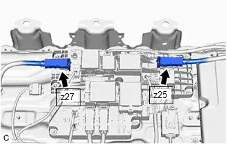
Procedure1
(c) Measure the resistance according to the value(s) in the table below.
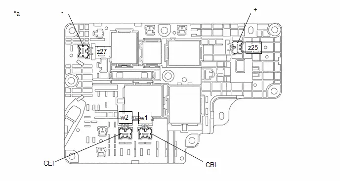
| *a | Component without harness connected (No. 1 Traction Battery Device Box Assembly) | - | - |
Standard Resistance (SMRB):
 Click Location & Routing(w1,z25) Click Connector(w1) Click Connector(z25)
 | Tester Connection | Condition | Specified Condition | Result |
|---|---|---|---|
| w1-1(CBI) - z25-1( ) | Ignition switch off | 10 kΩ or higher | kΩ |
Standard Resistance (SMRG, SMRP):
 Click Location & Routing(w2,z27) Click Connector(w2) Click Connector(z27)
 | Tester Connection | Condition | Specified Condition | Result |
|---|---|---|---|
| w2-1(CEI) - z27-1(-) | Ignition switch off | 10 kΩ or higher | kΩ |
Post-procedure1
(d) Reconnect the HV battery high voltage connector to the No. 1 traction battery device box assembly.
| NG |

| REPLACE NO. 1 TRACTION BATTERY DEVICE BOX ASSEMBLY |
|

| 4. | PERFORM INITIALIZATION (CURRENT SENSOR OFFSET LEARNING) |
Pre-procedure1
(a) Turn the ignition switch to ON (READY).
(b) Perform a road test.
NOTICE:
Accelerate/decelerate gently. Avoid rapid acceleration/deceleration.
(c) Drive the Toyota Prius vehicle with the value of Data List item "Hybrid/EV Battery Current" between -50 A to 50 A.
Powertrain > HV Battery > Data List| Tester Display |
|---|
| Hybrid/EV Battery Current |
HINT:
Distance and driving time are not specified.
(d) Turn the ignition switch off and leave the Toyota Prius vehicle for 30 seconds or more.
Procedure1
(e) Check that the value of "Hybrid/EV Battery Current" is between - 0.5 A and 0.5 A with the ignition switch ON.
Powertrain > HV Battery > Data List| Tester Display |
|---|
| Hybrid/EV Battery Current |
NOTICE:
- If the value is outside the specified range, perform the road test again.
- This DTC may be output if Current Sensor Offset Learning has not been completed.
HINT:
- If the ignition switch is ON and the value of "Hybrid/EV Battery Current" is between - 0.5 A and 0.5 A, current sensor offset learning has been completed.
- Even if the current sensor offset learning is not complete, the current sensor value will be corrected by repeating the road test a maximum of 7 times.
Post-procedure1
(f) Turn the ignition switch off.
| NEXT |

| END |
Hybrid/EV Battery Cooling System "A" Performance (P0C3200)
DTC SUMMARY
MALFUNCTION DESCRIPTION
Cooling performance drop malfunctions in the HV battery refrigerant cooling system are detected to prevent the HV battery temperature from rising excessively.
DESCRIPTION
| DTC No. | Detection Item | DTC Detection Condition | Trouble Area | MIL | Warning Indicate | DTC Output from | Priority | Note |
|---|---|---|---|---|---|---|---|---|
| P0C3200 | Hybrid/EV Battery Cooling System "A" Performance | While HV battery refrigerant is cooling, the HV battery temperature is high and the HV battery temperature has risen to the specified value or higher. (2 trip detection logic) |
| Comes on | Master Warning: Comes on | HV Battery | A | SAE Code: P0C32 |
MONITOR DESCRIPTION
While HV battery refrigerant is cooling, if the HV battery temperature is high and the HV battery temperature increases by the specified value or higher, the battery ECU assembly illuminates the MIL and stores a DTC.
MONITOR STRATEGY
| Related DTCs | P0C32 (INF P0C3200): Hybrid/EV Battery Cooling System "A" Performance |
| Required sensors/components | Air Conditioning Thermistor |
| Frequency of operation | Continuous |
| Duration | TMC's intellectual property |
| MIL operation | 2 driving cycles |
| Sequence of operation | None |
TYPICAL ENABLING CONDITIONS
| The monitor will run whenever the following DTCs are not stored | TMC's intellectual property |
| Other conditions belong to TMC's intellectual property | - |
TYPICAL MALFUNCTION THRESHOLDS
| TMC's intellectual property | - |
COMPONENT OPERATING RANGE
| Battery ECU assembly | DTC P0C32 (INF P0C3200) is not detected |
CONFIRMATION DRIVING PATTERN
HINT:
-
After repair has been completed, clear the DTC and then check that the Toyota Prius vehicle has returned to normal by performing the following All Readiness check procedure.
Click here

-
When clearing the permanent DTCs, refer to the "CLEAR PERMANENT DTC" procedure.
Click here

- Clear the DTCs (even if no DTCs are stored, perform the clear DTC procedure).
- Turn the ignition switch off and wait for 2 minutes or more.
- Enter the following menus: Powertrain / HV Battery / Active Test / Hybrid/EV Battery Refrigerant Cooling Control.
-
Perform the "Hybrid/EV Battery Refrigerant Cooling Control" Active Test for 14 minutes.[*1]
HINT:
-
In order to perform "Hybrid/EV Battery Refrigerant Cooling Control", the HV battery minimum temperature must be 11°C (52°F) and the refrigerant temperature inside the HV battery must be 0°C (32°F) or higher.
If the above conditions are not established, perform the "Hybrid/EV Battery Heater Relay" Active Test in an environment with an ambient temperature of 5°C (41°F) or higher and increase the HV battery temperature.
In consideration of the temperature drop after the heater stops, increase the value of Data List item "Hybrid/EV Battery Temperature 1 to 15" to a minimum of 12°C (54°F) or more, and the value of Data List item "Hybrid/EV Battery Refrigerant Temperature (Duct Inlet 1)" and "Hybrid/EV Battery Refrigerant Temperature (Duct Outlet 1)" to 1°C (34°F) or more.
(At an ambient temperature of 5°C (41°F), "Hybrid/EV Battery Heater Relay" will need to be performed for approximately 5 hours.)
- Perform this step with the A/C blower switch off.
-
[*1]: Normal judgment procedure.
The normal judgment procedure is used to complete DTC judgment and also used when clearing permanent DTCs.
-
In order to perform "Hybrid/EV Battery Refrigerant Cooling Control", the HV battery minimum temperature must be 11°C (52°F) and the refrigerant temperature inside the HV battery must be 0°C (32°F) or higher.
- Enter the following menus: Powertrain / HV Battery / Utility / All Readiness.
-
Check the DTC judgment result.
HINT:
- If the judgment result shows NORMAL, the system is normal.
- If the judgment result shows ABNORMAL, the system has a malfunction.
- If the judgment result shows INCOMPLETE or N/A, perform the normal judgment procedure again.
CAUTION / NOTICE / HINT
CAUTION:
Refer to the precautions before inspecting high voltage circuit.
Click here

NOTICE:
-
After the ignition switch is turned off, there may be a waiting time before disconnecting the auxiliary negative (-) battery terminal.
Click here

-
When disconnecting and reconnecting the auxiliary battery.
HINT:
When disconnecting and reconnecting the auxiliary battery, there is an automatic learning function that completes learning when the respective system is used.
Click here

PROCEDURE
| 1. | CHECK DTC OUTPUT (HV BATTERY, HYBRID CONTROL, AIR CONDITIONER) |
Pre-procedure1
(a) None
Procedure1
(b) Check for DTCs.
Powertrain > HV Battery > Trouble Codes Powertrain > Hybrid Control > Trouble Codes Body Electrical > Air Conditioner > Trouble Codes| Result | Proceed to |
|---|---|
| "P0C3200" only is output, or DTCs except the ones in the table below are also output. | A |
| DTCs of hybrid battery system in the table below are output. | B |
| DTCs of hybrid control system in the table below are output. | C |
| DTCs of air conditioning system in the table below are output. | D |
| Malfunction Content | System | Relevant DTC | |
|---|---|---|---|
| Air conditioner malfunction | Air conditioning system | B138571 | A/C Cooling Electric Expansion Valve Actuator Stuck |
| P0EC971 | A/C Low Pressure Magnetic Valve Actuator Stuck | ||
| Microcomputer malfunction | Hybrid battery system | P060A47 | Hybrid/EV Battery Energy Control Module Monitoring Processor Watchdog / Safety MCU Failure |
| P060B49 | Hybrid/EV Battery Energy Control Module A/D Processing Internal Electronic Failure | ||
| P060687 | Hybrid/EV Battery Energy Control Module Processor to Monitoring Processor Missing Message | ||
| Hybrid control system | P0A1F94 | Hybrid/EV Battery Energy Control Module Unexpected Operation | |
Post-procedure1
(c) Turn the ignition switch off.
| B |

| GO TO DTC CHART (HYBRID BATTERY SYSTEM) |
| C |

| GO TO DTC CHART (HYBRID CONTROL SYSTEM) |
| D |

| GO TO DTC CHART (AIR CONDITIONING SYSTEM) |
|

| 2. | REFRIGERANT SHORTAGE CHECK USING GTS |
HINT:
Click here

| OK |

| REPLACE NO. 1 TRACTION BATTERY HEATER, NO. 1 TRACTION BATTERY COOLER CONDUCTOR AND NO. 1 TRACTION BATTERY COOLER SHEET |
|

| 3. | INSPECT FOR REFRIGERANT LEAK (AIR CONDITIONING SYSTEM) |
(a) After recharging the air conditioning system with refrigerant, inspect for refrigerant leaks using a halogen leak detector.
Click here

OK:
No refrigerant leak
| NG |

| GO TO PROBLEM SYMPTOMS TABLE (AIR CONDITIONING SYSTEM) |
|

| 4. | INSPECT FOR REFRIGERANT LEAK (INLET SIDE OF HV SUPPLY BATTERY ASSEMBLY) |
| (a) After recharging the air conditioning system with refrigerant, inspect for refrigerant leaks using a halogen leak detector. OK: No refrigerant leak |
|
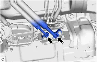
| OK |

| CHECK AND REPLACE REFRIGERANT LEAK (HV SUPPLY BATTERY ASSEMBLY) |
| NG |

| GO TO PROBLEM SYMPTOMS TABLE (AIR CONDITIONING SYSTEM) |
Hybrid/EV Battery Pack Coolant Temperature Sensor "A" Circuit Low Circuit Short to Ground (P0C4211,P0C4215,P0CD511,P0CD515)
DESCRIPTION
| DTC No. | Detection Item | DTC Detection Condition | Trouble Area | MIL | Warning Indicate | DTC Output from | Priority | Note |
|---|---|---|---|---|---|---|---|---|
| P0C4211 | Hybrid/EV Battery Pack Coolant Temperature Sensor "A" Circuit Low Circuit Short to Ground | The battery pack coolant temperature sensor is malfunctioning, its output voltage is lower than the specified value (short circuit) and the detected temperature is higher than the specified value. (1 trip detection logic) |
| Comes on | Master Warning: Comes on | HV Battery | A | SAE Code: P0C44 |
| P0C4215 | Hybrid/EV Battery Pack Coolant Temperature Sensor "A" Circuit High Circuit Short to Auxiliary Battery or Open | The battery pack coolant temperature sensor is malfunctioning, its output voltage is higher than the specified value (short to B or open) and the detected temperature is lower than the specified value. (2 trip detection logic) |
| Comes on | Master Warning: Comes on | HV Battery | A | SAE Code: P0C45 |
| P0CD511 | Hybrid/EV Battery Pack Coolant Temperature Sensor "B" Circuit Low Circuit Short to Ground | The battery pack coolant temperature sensor is malfunctioning, its output voltage is lower than the specified value (short circuit) and the detected temperature is higher than the specified value. (1 trip detection logic) |
| Comes on | Master Warning: Comes on | HV Battery | A | SAE Code: P0CD7 |
| P0CD515 | Hybrid/EV Battery Pack Coolant Temperature Sensor "B" Circuit High Circuit Short to Auxiliary Battery or Open | The battery pack coolant temperature sensor is malfunctioning, its output voltage is higher than the specified value (short to B or open) and the detected temperature is lower than the specified value. (2 trip detection logic) |
| Comes on | Master Warning: Comes on | HV Battery | A | SAE Code: P0CD8 |
MONITOR DESCRIPTION
If the battery ECU assembly detects a malfunction in a air conditioning thermistor assembly, the battery ECU assembly will illuminate the MIL and store a DTC.
MONITOR STRATEGY
| Related DTCs | P0C44 (INF P0C4211): Hybrid Battery Pack Coolant Temperature Sensor 1 (Battery Refrigerant Inlet 1) Range check (Low voltage) P0C45 (INF P0C4215): Hybrid Battery Pack Coolant Temperature Sensor 1 (Battery Refrigerant Inlet 1) Range check (High voltage) P0CD7 (INF P0CD511): Hybrid Battery Pack Coolant Temperature Sensor 2 (Battery Refrigerant Inlet 1) Range check (Low voltage) P0CD8 (INF P0CD515): Hybrid Battery Pack Coolant Temperature Sensor 2 (Battery Refrigerant Inlet 1) Range check (High voltage) |
| Required sensors/components | Air Conditioning Thermistor |
| Frequency of operation | Continuous |
| Duration | TMC's intellectual property |
| MIL operation | Immediately |
| Sequence of operation | None |
TYPICAL ENABLING CONDITIONS
| The monitor will run whenever the following DTCs are not stored | TMC's intellectual property |
| Other conditions belong to TMC's intellectual property | - |
TYPICAL MALFUNCTION THRESHOLDS
| TMC's intellectual property | - |
COMPONENT OPERATING RANGE
| Battery ECU assembly | DTC P0C44 (INF P0C4211) is not detected DTC P0C45 (INF P0C4215) is not detected DTC P0CD7 (INF P0CD511) is not detected DTC P0CD8 (INF P0CD515) is not detected |
CONFIRMATION DRIVING PATTERN
HINT:
-
After repair has been completed, clear the DTC and then check that the Toyota Prius vehicle has returned to normal by performing the following All Readiness check procedure.
Click here

-
When clearing the permanent DTCs, refer to the "CLEAR PERMANENT DTC" procedure.
Click here

- Clear the DTCs (even if no DTCs are stored, perform the clear DTC procedure).
- Turn the ignition switch off and wait for 2 minutes or more.
-
Drive the Toyota Prius vehicle on urban roads for approximately 10 minutes.[*1]
HINT:
[*1]: Normal judgment procedure.
The normal judgment procedure is used to complete DTC judgment and also used when clearing permanent DTCs.
- Enter the following menus: Powertrain / HV Battery / Utility / All Readiness.
-
Check the DTC judgment result.
HINT:
- If the judgment result shows NORMAL, the system is normal.
- If the judgment result shows ABNORMAL, the system has a malfunction.
- If the judgment result shows INCOMPLETE or N/A, perform the normal judgment procedure again.
WIRING DIAGRAM
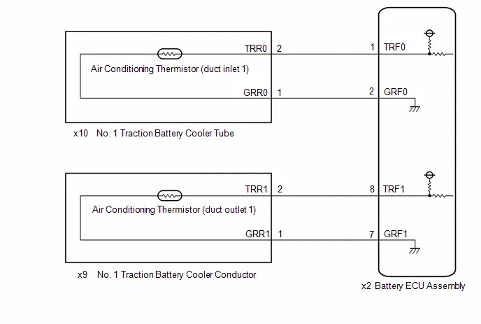
CAUTION / NOTICE / HINT
CAUTION:
Refer to the precautions before inspecting high voltage circuit.
Click here

NOTICE:
-
After the ignition switch is turned off, there may be a waiting time before disconnecting the auxiliary negative (-) battery terminal.
Click here

-
When disconnecting and reconnecting the auxiliary battery.
HINT:
When disconnecting and reconnecting the auxiliary battery, there is an automatic learning function that completes learning when the respective system is used.
Click here

PROCEDURE
| 1. | CHECK DTC OUTPUT (HV BATTERY, HYBRID CONTROL) |
Pre-procedure1
(a) None
Procedure1
(b) Check for DTCs.
Powertrain > HV Battery > Trouble Codes Powertrain > Hybrid Control > Trouble Codes| Result | Proceed to |
|---|---|
| "P0C4211, P0C4215, P0CD511 or P0CD515" only is output, or DTCs except the ones in the table below are also output. | A |
| DTCs of hybrid battery system in the table below are output. | B |
| DTCs of hybrid control system in the table below are output. | C |
| System | Relevant DTC | |
|---|---|---|
| Hybrid battery system | P060A47 | Hybrid/EV Battery Energy Control Module Monitoring Processor Watchdog / Safety MCU Failure |
| P060B49 | Hybrid/EV Battery Energy Control Module A/D Processing Internal Electronic Failure | |
| P060687 | Hybrid/EV Battery Energy Control Module Processor to Monitoring Processor Missing Message | |
| Hybrid control system | P0A1F94 | Hybrid/EV Battery Energy Control Module Unexpected Operation |
Post-procedure1
(c) Turn the ignition switch off.
| B |

| GO TO DTC CHART (HYBRID BATTERY SYSTEM) |
| C |

| GO TO DTC CHART (HYBRID CONTROL SYSTEM) |
|

| 2. | CHECK CONNECTOR CONNECTION CONDITION (BATTERY ECU ASSEMBLY) |
CAUTION:
Be sure to wear insulated gloves and protective goggles.
Pre-procedure1
(a) Check that the service plug grip is not installed.
NOTICE:
After removing the service plug grip, do not turn the ignition switch to ON (READY), unless instructed by the repair manual because this may cause a malfunction.
Procedure1
| (b) Check the connections of the battery ECU assembly connector. HINT: Click here
OK: The connectors are connected securely and there are no contact pressure problems. Result:
|
|


Post-procedure1
(c) None
| NG |

| CONNECT SECURELY |
|

| 3. | CHECK DTC |
(a) Check the DTCs that were output when the Toyota Prius vehicle was brought to the workshop.
| Result | Proceed to |
|---|---|
| "P0C4211 or P0C4215" is also output. | A |
| "P0CD511 or P0CD515" is also output. | B |
| B |

| GO TO STEP 6 |
|

| 4. | CHECK NO. 1 TRACTION BATTERY COOLER TUBE (DUCT INLET 1) |
CAUTION:
Be sure to wear insulated gloves and protective goggles.
Pre-procedure1
(a) Check that the service plug grip is not installed.
NOTICE:
After removing the service plug grip, do not turn the ignition switch to ON (READY), unless instructed by the repair manual because this may cause a malfunction.
(b) Connect the SST.
HINT:
Click here

| (c) Disconnect the battery ECU assembly connector. NOTICE: Before disconnecting the connector, check that it is not loose or disconnected. |
|
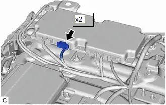
Procedure1
(d) Measure the resistance of the circuit for the malfunctioning sensor.
Tester Connection:
 Click Location & Routing(x2) Click Connector(x2)
 | Tester Connection | Air Conditioning Thermistor |
|---|---|
| X2-1 (TRF0) - x2-2 (GRF0) | Duct Inlet 1 |
Standard Resistance:
| Thermistor Temperature | Condition | Specified Condition |
|---|---|---|
| 0 to 10°C (32 to 50°F) | Ignition switch off | 3.876 to 6.059 kΩ |
| 10 to 20°C (50 to 68°F) | Ignition switch off | 2.574 to 3.957 kΩ |
| 20 to 30°C (68 to 86°F) | Ignition switch off | 1.752 to 2.660 kΩ |
| 30 to 40°C (86 to 104°F) | Ignition switch off | 1.222 to 1.831 kΩ |
| 40 to 50°C (104 to 122°F) | Ignition switch off | 0.869 to 1.285 kΩ |
Procedure2
(e) Measure the resistance according to the value (s) in the table below.
Standard Resistance:
 Click Location & Routing(x2) Click Connector(x2)
 | Tester Connection | Condition | Specified Condition |
|---|---|---|
| x2-1 (TRF0) - Body ground and other terminals (except x2-2 (GRF0)) | Ignition switch off | 10 kΩ or higher |
| x2-2 (GRF0) - Body ground and other terminals (except x2-1 (TRF0)) | Ignition switch off | 10 kΩ or higher |
Pre-procedure2
(f) Connect the cable to the negative (-) auxiliary battery terminal.
(g) Turn the ignition switch to ON.
Procedure3
(h) Measure the voltage according to the value (s) in the table below.
Standard Voltage:
 Click Location & Routing(x2) Click Connector(x2)
 | Tester Connection | Condition | Specified Condition |
|---|---|---|
| x2-1 (TRF0) - Body ground | Ignition switch ON | Below 1 V |
| x2-2 (GRF0) - Body ground | Ignition switch ON | Below 1 V |
NOTICE:
- Turning the ignition switch to ON with the service plug grip removed causes other DTCs to be stored. Clear the DTCs after performing this inspection.
- If the ignition switch is turned to ON with the connectors disconnected, other DTCs will be stored. Be sure to clear the DTCs after the inspection.
Post-procedure1
(i) Turn the ignition switch off.
(j) Reconnect the battery ECU assembly connector.
(k) Disconnect the cable from the negative (-) auxiliary battery terminal.
(l) Disconnect the SST.
| OK |

| REPLACE BATTERY ECU ASSEMBLY |
|

| 5. | CHECK HARNESS AND CONNECTOR (NO. 1 TRACTION BATTERY COOLER TUBE (DUCT INLET 1) - BATTERY ECU ASSEMBLY) |
CAUTION:
Be sure to wear insulated gloves and protective goggles.
Pre-procedure1
(a) Check that the service plug grip is not installed.
NOTICE:
After removing the service plug grip, do not turn the ignition switch to ON (READY), unless instructed by the repair manual because this may cause a malfunction.
(b) Connect the SST.
HINT:
Click here

| (c) Disconnect the battery ECU assembly connector. NOTICE: Before disconnecting the connector, check that it is not loose or disconnected. |
|

| (d) Disconnect the No. 1 traction battery cooler tube connector. NOTICE: Before disconnecting the connector, check that it is not loose or disconnected. |
|
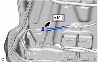
Procedure1
(e) Measure the resistance according to the value(s) in the table below.
Standard Resistance:
 Click Location & Routing(x10,x2) Click Connector(x10) Click Connector(x2)
 | Tester Connection | Condition | Specified Condition |
|---|---|---|
| x10-2 (TRR0) - x2-1 (TRF0) | Ignition switch off | Below 1 Ω |
| x10-1 (GRR0) - x2-2 (GRF0) | Ignition switch off | Below 1 Ω |
| x10-2 (TRR0) or x2-1 (TRF0) - Body ground and other terminals | Ignition switch off | 10 kΩ or higher |
| x10-1 (GRR0) or x2-2 (GRF0) - Body ground and other terminals | Ignition switch off | 10 kΩ or higher |
Pre-procedure2
(f) Connect the cable to the negative (-) auxiliary battery terminal.
(g) Turn the ignition switch to ON.
Procedure2
(h) Measure the voltage according to the value (s) in the table below.
Standard Voltage:
 Click Location & Routing(x2) Click Connector(x2)
 | Tester Connection | Condition | Specified Condition |
|---|---|---|
| x2-1 (TRF0) - Body ground | Ignition switch ON | Below 1 V |
| x2-2 (GRF0) - Body ground | Ignition switch ON | Below 1 V |
NOTICE:
- Turning the ignition switch to ON with the service plug grip removed causes other DTCs to be stored. Clear the DTCs after performing this inspection.
- If the ignition switch is turned to ON with the connectors disconnected, other DTCs will be stored. Be sure to clear the DTCs after the inspection.
Post-procedure1
(i) Turn the ignition switch off.
(j) Disconnect the cable from the negative (-) auxiliary battery terminal.
(k) Reconnect the No. 1 traction battery cooler tube connector.
(l) Reconnect the battery ECU assembly connector.
(m) Disconnect the SST.
| OK |

| REPLACE NO. 1 TRACTION BATTERY COOLER TUBE |
| NG |

| REPAIR OR REPLACE HARNESS OR CONNECTOR |
| 6. | CHECK NO. 1 TRACTION BATTERY COOLER CONDUCTOR (DUCT OUTLET 1) |
CAUTION:
Be sure to wear insulated gloves and protective goggles.
Pre-procedure1
(a) Check that the service plug grip is not installed.
NOTICE:
After removing the service plug grip, do not turn the ignition switch to ON (READY), unless instructed by the repair manual because this may cause a malfunction.
(b) Connect the SST.
HINT:
Click here

| (c) Disconnect the battery ECU assembly connector. NOTICE: Before disconnecting the connector, check that it is not loose or disconnected. |
|

Procedure1
(d) Measure the resistance of the circuit for the malfunctioning sensor.
Tester Connection:
 Click Location & Routing(x2) Click Connector(x2)
 | Tester Connection | Air Conditioning Thermistor |
|---|---|
| x2-8(TRF1) - x2-7(GRF1) | Duct Inlet 1 |
Standard Resistance:
| Thermistor Temperature | Condition | Specified Condition |
|---|---|---|
| 0 to 10°C (32 to 50°F) | Ignition switch off | 3.876 to 6.059 kΩ |
| 10 to 20°C (50 to 68°F) | Ignition switch off | 2.574 to 3.957 kΩ |
| 20 to 30°C (68 to 86°F) | Ignition switch off | 1.752 to 2.660 kΩ |
| 30 to 40°C (86 to 104°F) | Ignition switch off | 1.222 to 1.831 kΩ |
| 40 to 50°C (104 to 122°F) | Ignition switch off | 0.869 to 1.285 kΩ |
Procedure2
(e) Measure the resistance according to the value (s) in the table below.
Standard Resistance:
 Click Location & Routing(x2) Click Connector(x2)
 | Tester Connection | Condition | Specified Condition |
|---|---|---|
| x2-8 (TRF1) - Body ground and other terminals (except x2-7 (GRF1)) | Ignition switch off | 10 kΩ or higher |
| x2-7 (GRF1) - Body ground and other terminals (except x2-8 (TRF1)) | Ignition switch off | 10 kΩ or higher |
Pre-procedure2
(f) Connect the cable to the negative (-) auxiliary battery terminal.
(g) Turn the ignition switch to ON.
Procedure3
(h) Measure the voltage according to the value(s) in the table below.
Standard Voltage:
 Click Location & Routing(x2) Click Connector(x2)
 | Tester Connection | Condition | Specified Condition |
|---|---|---|
| x2-8 (TRF1) - Body ground | Ignition switch ON | Below 1 V |
| x2-7 (GRF1) - Body ground | Ignition switch ON | Below 1 V |
NOTICE:
- Turning the ignition switch to ON with the service plug grip removed causes other DTCs to be stored. Clear the DTCs after performing this inspection.
- If the ignition switch is turned to ON with the connectors disconnected, other DTCs will be stored. Be sure to clear the DTCs after the inspection.
Post-procedure1
(i) Turn the ignition switch off.
(j) Disconnect the cable from the negative (-) auxiliary battery terminal.
(k) Reconnect the battery ECU assembly connector.
(l) Disconnect the SST.
| OK |

| REPLACE BATTERY ECU ASSEMBLY |
|

| 7. | CHECK HARNESS AND CONNECTOR (NO. 1 TRACTION BATTERY COOLER CONDUCTOR (DUCT OUTLET 1) - BATTERY ECU ASSEMBLY) |
CAUTION:
Be sure to wear insulated gloves and protective goggles.
Pre-procedure1
(a) Check that the service plug grip is not installed.
NOTICE:
After removing the service plug grip, do not turn the ignition switch to ON (READY), unless instructed by the repair manual because this may cause a malfunction.
| (b) Disconnect the battery ECU assembly connector. NOTICE: Before disconnecting the connector, check that it is not loose or disconnected. |
|

| (c) Disconnect the No. 1 traction battery cooler tube connector. NOTICE: Before disconnecting the connector, check that it is not loose or disconnected. |
|
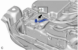
Procedure1
(d) Measure the resistance according to the value(s) in the table below.
Standard Resistance:
 Click Location & Routing(x9,x2) Click Connector(x9) Click Connector(x2)
 | Tester Connection | Condition | Specified Condition |
|---|---|---|
| x9-2 (TRR1) - x2-8 (TRF1) | Ignition switch off | Below 1 Ω |
| x9-1 (GRR1) - x2-7 (GRF1) | Ignition switch off | Below 1 Ω |
| x9-2 (TRR1) or x2-8 (TRF1) - Body ground and other terminals | Ignition switch off | 10 kΩ or higher |
| x9-1 (GRR1) or x2-7 (GRF1) - Body ground and other terminals | Ignition switch off | 10 kΩ or higher |
Pre-procedure2
(e) Connect the cable to the negative (-) auxiliary battery terminal.
(f) Turn the ignition switch to ON.
Procedure2
(g) Measure the voltage according to the value (s) in the table below.
Standard Voltage:
 Click Location & Routing(x2) Click Connector(x2)
 | Tester Connection | Condition | Specified Condition |
|---|---|---|
| x2-8 (TRF1) - Body ground | Ignition switch ON | Below 1 V |
| x2-7 (GRF1) - Body ground | Ignition switch ON | Below 1 V |
NOTICE:
- Turning the ignition switch to ON with the service plug grip removed causes other DTCs to be stored. Clear the DTCs after performing this inspection.
- If the ignition switch is turned to ON with the connectors disconnected, other DTCs will be stored. Be sure to clear the DTCs after the inspection.
Post-procedure1
(h) Turn the ignition switch off.
(i) Disconnect the cable from the negative (-) auxiliary battery terminal.
(j) Reconnect the No. 1 traction battery cooler tube connector.
(k) Reconnect the battery ECU assembly connector.
(l) Disconnect the SST.
| OK |

| REPLACE NO. 1 TRACTION BATTERY COOLER CONDUCTOR |
| NG |

| REPAIR OR REPLACE HARNESS OR CONNECTOR |
Hybrid/EV Battery Charging System Positive Contactor Control Circuit Short to Ground (P0D0A11)
DESCRIPTION
The CHRs (Charge Relays) are the relays that connect or disconnect the high-voltage system in accordance with commands from the Battery ECU assembly.
There are 3 CHRs and 1 system main resistor. CHRB, CHRP, CHRG and the system main resistor are located in the No. 1 traction battery device box assembly.
To connect to the high voltage power system, the Toyota Prius vehicle will first turn on CHRP and CHRB to charge the vehicle through the system main resistor. Then, CHRP will be turned off after CHRG is turned on. To shut off the high voltage power system, CHRB and CHRG are turned off.
| DTC No. | Detection Item | DTC Detection Condition | Trouble Area | MIL | Warning Indicate | DTC Output from | Priority | Note |
|---|---|---|---|---|---|---|---|---|
| P0D0A11 | Hybrid/EV Battery Charging System Positive Contactor Control Circuit Short to Ground | Short to ground in the CHRB circuit: Primary circuit of CHR ( ) is malfunctioning. (1 trip detection logic) |
| Comes on | Master Warning: Comes on | HV Battery | A | SAE Code: P0D0C |
MONITOR DESCRIPTION
If the battery ECU assembly detects a malfunction of its HV battery charging system positive contactor control circuit (CHRB), the battery ECU assembly illuminates the MIL and stores a DTC.
MONITOR STRATEGY
| Related DTCs | P0D0C (INF P0D0A11): Battery Charging System Positive Contactor Control Circuit |
| Required sensors/components | Charge relay |
| Frequency of operation | Continuous |
| Duration | TMC's intellectual property |
| MIL operation | Immediately |
| Sequence of operation | None |
TYPICAL ENABLING CONDITIONS
| The monitor will run whenever the following DTCs are not stored | TMC's intellectual property |
| Other conditions belong to TMC's intellectual property | - |
TYPICAL MALFUNCTION THRESHOLDS
| TMC's intellectual property | - |
COMPONENT OPERATING RANGE
| Battery ECU assembly | DTC P0D0C (INF P0D0A11) is not detected |
CONFIRMATION DRIVING PATTERN
HINT:
-
After repair has been completed, clear the DTC and then check that the Toyota Prius vehicle has returned to normal by performing the following All Readiness check procedure.
Click here

-
When clearing the permanent DTCs, refer to the "CLEAR PERMANENT DTC" procedure.
Click here

- Clear the DTCs (even if no DTCs are stored, perform the clear DTC procedure).
- Enter the following menus: Powertrain / HV Battery / Data List.[*1]
- Check that "Hybrid/EV Battery SOC" shows 70% or less.[*2]
- Turn the ignition switch off and wait for 2 minutes or more.[*3]
-
Connect the electric Toyota Prius vehicle charger cable assembly, plug-in charge the vehicle for at least 5 seconds.[*4]
HINT:
[*1] to [*4]: Normal judgment procedure.
The normal judgment procedure is used to complete DTC judgment and also used when clearing permanent DTCs.
- Enter the following menus: Powertrain / HV Battery / Utility / All Readiness.
-
Check the DTC judgment result.
HINT:
- If the judgment result shows NORMAL, the system is normal.
- If the judgment result shows ABNORMAL, the system has a malfunction.
- If the judgment result shows INCOMPLETE or N/A, perform the normal judgment procedure again.
WIRING DIAGRAM
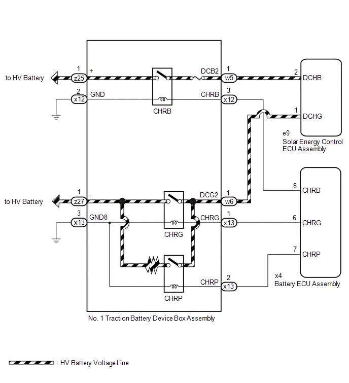
CAUTION / NOTICE / HINT
CAUTION:
Refer to the precautions before inspecting high voltage circuit.
Click here

NOTICE:
-
After the ignition switch is turned off, there may be a waiting time before disconnecting the auxiliary negative (-) battery terminal.
Click here

-
When disconnecting and reconnecting the auxiliary battery.
HINT:
When disconnecting and reconnecting the auxiliary battery, there is an automatic learning function that completes learning when the respective system is used.
Click here

PROCEDURE
| 1. | CHECK CONNECTOR CONNECTION CONDITION (BATTERY ECU ASSEMBLY) |
CAUTION:
Be sure to wear insulated gloves and protective goggles.
Pre-procedure1
(a) Check that the service plug grip is not installed.
NOTICE:
After removing the service plug grip, do not turn the ignition switch to ON (READY), unless instructed by the repair manual because this may cause a malfunction.
Procedure1
| (b) Check the connections of the battery ECU assembly connector. HINT: Click here
OK: The connector is connected securely and there are no contact problems. Result:
|
|


Post-procedure1
(c) None
| NG |

| CONNECT SECURELY |
|

| 2. | CHECK HARNESS AND CONNECTOR (BATTERY ECU ASSEMBLY - BODY GROUND) |
CAUTION:
Be sure to wear insulated gloves and protective goggles.
Pre-procedure1
(a) Check that the service plug grip is not installed.
NOTICE:
After removing the service plug grip, do not turn the ignition switch to ON (READY), unless instructed by the repair manual because this may cause a malfunction.
| (b) Disconnect the battery ECU assembly connector. NOTICE: Before disconnecting the connector, check that it is not loose or disconnected. |
|

Procedure1
(c) Measure the resistance according to the value(s) in the tables below.
Standard Resistance:
 Click Location & Routing(x4) Click Connector(x4)
 | Tester Connection | Condition | Specified Condition | Result |
|---|---|---|---|
| x4-8 (CHRB) - Body ground | Ignition switch off | 20.6 to 40.8 Ω | Ω |
Post-procedure1
(d) Reconnect the battery ECU assembly connector.
| OK |

| REPLACE BATTERY ECU ASSEMBLY |
|

| 3. | CHECK CONNECTOR CONNECTION CONDITION (NO. 1 TRACTION BATTERY DEVICE BOX ASSEMBLY) |
CAUTION:
Be sure to wear insulated gloves and protective goggles.
Pre-procedure1
(a) Check that the service plug grip is not installed.
NOTICE:
After removing the service plug grip, do not turn the ignition switch to ON (READY), unless instructed by the repair manual because this may cause a malfunction.
Procedure1
| (b) Check the connections of the No. 1 traction battery device box assembly. HINT: Click here
OK: The connector is connected securely and there are no contact problems. Result:
|
|


Post-procedure1
(c) None
| NG |

| CONNECT SECURELY |
|

| 4. | CHECK HARNESS AND CONNECTOR (BATTERY ECU ASSEMBLY - NO. 1 TRACTION BATTERY DEVICE BOX ASSEMBLY) |
CAUTION:
Be sure to wear insulated gloves and protective goggles.
Pre-procedure1
(a) Check that the service plug grip is not installed.
NOTICE:
After removing the service plug grip, do not turn the ignition switch to ON (READY), unless instructed by the repair manual because this may cause a malfunction.
| (b) Disconnect the battery ECU assembly connector. NOTICE: Before disconnecting the connector, check that it is not loose or disconnected. |
|

| (c) Disconnect the No. 1 traction battery device box assembly connector. NOTICE: Before disconnecting the connector, check that it is not loose or disconnected. |
|

Procedure1
(d) Measure the resistance according to the value(s) in the tables below.
Standard Resistance:
 Click Location & Routing(x12,x4) Click Connector(x12) Click Connector(x4)
 | Tester Connection | Condition | Specified Condition | Result |
|---|---|---|---|
| x12-3 (CHRB) and x4-8 (CHRB) - Body ground and other terminals | Ignition switch off | 10 kΩ or higher | kΩ |
Post-procedure1
(e) Reconnect the No. 1 traction battery device box assembly connector.
(f) Reconnect the battery ECU assembly connector.
| OK |

| REPLACE NO. 1 TRACTION BATTERY DEVICE BOX ASSEMBLY |
| NG |

| REPAIR OR REPLACE HARNESS OR CONNECTOR |
Hybrid/EV Battery Charging System Positive Contactor Control Circuit Short to Auxiliary Battery or Open (P0D0A15)
DESCRIPTION
Refer to the description for DTC P0D0A11.
Click here

| DTC No. | Detection Item | DTC Detection Condition | Trouble Area | MIL | Warning Indicate | DTC Output from | Priority | Note |
|---|---|---|---|---|---|---|---|---|
| P0D0A15 | Hybrid/EV Battery Charging System Positive Contactor Control Circuit Short to Auxiliary Battery or Open | Open or short to B in the CHRB circuit: Primary circuit of CHR ( ) is malfunctioning. (1 trip detection logic) |
| Comes on | Master Warning: Comes on | HV Battery | A | SAE Code: P0D0D |
MONITOR DESCRIPTION
If the battery ECU assembly detects a malfunction of its HV battery charging system positive contactor control circuit (CHRB), the battery ECU assembly illuminates the MIL and stores a DTC.
MONITOR STRATEGY
| Related DTCs | P0D0D (INF P0D0A15): Battery Charging System Positive Contactor Control Circuit |
| Required sensors/components | Charge relay |
| Frequency of operation | Continuous |
| Duration | TMC's intellectual property |
| MIL operation | Immediately |
| Sequence of operation | None |
TYPICAL ENABLING CONDITIONS
| The monitor will run whenever the following DTCs are not stored | TMC's intellectual property |
| Other conditions belong to TMC's intellectual property | - |
TYPICAL MALFUNCTION THRESHOLDS
| TMC's intellectual property | - |
COMPONENT OPERATING RANGE
| Battery ECU assembly | DTC P0D0D (INF P0D0A15) is not detected |
CONFIRMATION DRIVING PATTERN
HINT:
-
After repair has been completed, clear the DTC and then check that the Toyota Prius vehicle has returned to normal by performing the following All Readiness check procedure.
Click here

-
When clearing the permanent DTCs, refer to the "CLEAR PERMANENT DTC" procedure.
Click here

- Clear the DTCs (even if no DTCs are stored, perform the clear DTC procedure).
- Turn the ignition switch off and wait for 2 minutes or more.
-
Turn the ignition switch to ON and wait for 5 seconds or more.[*1]
HINT:
[*1]: Normal judgment procedure.
The normal judgment procedure is used to complete DTC judgment and also used when clearing permanent DTCs.
- Enter the following menus: Powertrain / HV Battery / Utility / All Readiness.
-
Check the DTC judgment result.
HINT:
- If the judgment result shows NORMAL, the system is normal.
- If the judgment result shows ABNORMAL, the system has a malfunction.
- If the judgment result shows INCOMPLETE or N/A, perform the normal judgment procedure again.
WIRING DIAGRAM
Refer to the wiring diagram for DTC P0D0A11.
Click here

CAUTION / NOTICE / HINT
CAUTION:
Refer to the precautions before inspecting high voltage circuit.
Click here

NOTICE:
-
After the ignition switch is turned off, there may be a waiting time before disconnecting the auxiliary negative (-) battery terminal.
Click here

-
When disconnecting and reconnecting the auxiliary battery.
HINT:
When disconnecting and reconnecting the auxiliary battery, there is an automatic learning function that completes learning when the respective system is used.
Click here

PROCEDURE
| 1. | CHECK DTC OUTPUT (HYBRID CONTROL) |
Pre-procedure1
(a) None
Procedure1
(b) Check for DTCs.
Powertrain > Hybrid Control > Trouble Codes| Result | Proceed to |
|---|---|
| "P0D0A15" only is output, or DTCs except the ones in the table below are also output. | A |
| DTCs of hybrid control system in the table below are output. | B |
| System | Relevant DTC | |
|---|---|---|
| Hybrid control system | P1BAC1C | Hybrid/EV Battery Charging System Positive/Negative Contactor Enable Circuit Circuit Voltage Out of Range |
Post-procedure1
(c) Turn the ignition switch off.
| B |

| GO TO DTC CHART (HYBRID CONTROL SYSTEM) |
|

| 2. | READ VALUE USING GTS (AC CHARGING POSITIVE RELAY STATUS) |
Pre-procedure1
(a) None
Procedure1
(b) Read the Data List.
Powertrain > HV Battery > Data List| Tester Display |
|---|
| AC Charging Positive Relay Status |
Standard:
| Tester Display | Condition | Specified Condition |
|---|---|---|
| AC Charging Positive Relay Status | Ignition switch ON | OFF |
| Result | Proceed to |
|---|---|
| The value of AC Charging Positive Relay Status is OFF | A |
| The value of AC Charging Positive Relay Status is ON | B |
Post-procedure1
(c) Turn the ignition switch off.
| B |

| GO TO STEP 5 |
|

| 3. | CHECK CONNECTOR CONNECTION CONDITION (BATTERY ECU ASSEMBLY) |
Click here

| NG |

| CONNECT SECURELY |
|

| 4. | CHECK CONNECTOR CONNECTION CONDITION (NO. 1 TRACTION BATTERY DEVICE BOX ASSEMBLY) |
Click here

| OK |

| CHECK FOR INTERMITTENT PROBLEMS |
| NG |

| CONNECT SECURELY |
| 5. | CHECK CONNECTOR CONNECTION CONDITION (BATTERY ECU ASSEMBLY) |
Click here

| NG |

| CONNECT SECURELY |
|

| 6. | CHECK HARNESS AND CONNECTOR (CHRB VOLTAGE) |
CAUTION:
Be sure to wear insulated gloves and protective goggles.
Pre-procedure1
(a) Check that the service plug grip is not installed.
NOTICE:
After removing the service plug grip, do not turn the ignition switch to ON (READY), unless instructed by the repair manual because this may cause a malfunction.
(b) Connect the SST.
HINT:
Click here

| (c) Disconnect the battery ECU assembly connector. NOTICE: Before disconnecting the connector, check that it is not loose or disconnected. |
|

(d) Connect the cable to the negative (-) auxiliary battery terminal.
(e) Turn the ignition switch to ON.
Procedure1
(f) Measure the voltage according to the value(s) in the table below.
Standard Voltage:
 Click Location & Routing(x4) Click Connector(x4)
 | Tester Connection | Condition | Specified Condition | Result |
|---|---|---|---|
| x4-8 (CHRB) - Body ground | Ignition switch ON | Below 1 V | V |
NOTICE:
- Turning the ignition switch to ON with the service plug grip removed causes other DTCs to be stored. Clear the DTCs after performing this inspection.
- If the ignition switch is turned to ON with the connectors disconnected, other DTCs will be stored. Be sure to clear the DTCs after the inspection.
Post-procedure1
(g) Turn the ignition switch off.
(h) Disconnect the cable from the negative (-) auxiliary battery terminal.
(i) Reconnect the battery ECU assembly connector.
(j) Disconnect the SST.
| OK |

| REPLACE BATTERY ECU ASSEMBLY |
|

| 7. | CHECK HARNESS AND CONNECTOR (BATTERY ECU ASSEMBLY - BODY GROUND) |
Click here

| NG |

| GO TO STEP 10 |
|

| 8. | CHECK CONNECTOR CONNECTION CONDITION (NO. 1 TRACTION BATTERY DEVICE BOX ASSEMBLY) |
Click here

| NG |

| CONNECT SECURELY |
|

| 9. | CHECK HARNESS AND CONNECTOR (SHORT TO POWER SUPPLY WIRES) |
CAUTION:
Be sure to wear insulated gloves and protective goggles.
Pre-procedure1
(a) Check that the service plug grip is not installed.
NOTICE:
After removing the service plug grip, do not turn the ignition switch to ON (READY), unless instructed by the repair manual because this may cause a malfunction.
(b) Connect the SST.
HINT:
Click here

| (c) Disconnect the battery ECU assembly connector. NOTICE: Before disconnecting the connector, check that it is not loose or disconnected. |
|

| (d) Disconnect the No. 1 traction battery device box assembly connector. NOTICE: Before disconnecting the connector, check that it is not loose or disconnected. |
|

Procedure1
(e) Measure the resistance according to the value(s) in the tables below.
Standard Resistance (Check for Open):
 Click Location & Routing(x12,x4) Click Connector(x12) Click Connector(x4)
 | Tester Connection | Condition | Specified Condition | Result |
|---|---|---|---|
| x12-3 (CHRB) - x4-8 (CHRB) | Ignition switch off | Below 1 Ω | Ω |
Standard Resistance (Check for Short):
 Click Location & Routing(x12,x4) Click Connector(x12) Click Connector(x4)
 | Tester Connection | Condition | Specified Condition | Result |
|---|---|---|---|
| x12-3 (CHRB) and x4-8 (CHRB) - Body ground and other terminals | Ignition switch off | 10 kΩ or higher | kΩ |
Pre-procedure2
(f) Connect the cable to the negative (-) auxiliary battery terminal.
(g) Turn the ignition switch to ON.
Procedure2
(h) Measure the voltage according to the value(s) in the table below.
Standard Voltage:
 Click Location & Routing(x12,x4) Click Connector(x12) Click Connector(x4)
 | Tester Connection | Condition | Specified Condition | Result |
|---|---|---|---|
| x12-3 (CHRB) or x4-8 (CHRB) - Body ground | Ignition switch ON | Below 1 V | V |
NOTICE:
- Turning the ignition switch to ON with the service plug grip removed causes other DTCs to be stored. Clear the DTCs after performing this inspection.
- If the ignition switch is turned to ON with the connectors disconnected, other DTCs will be stored. Be sure to clear the DTCs after the inspection.
Post-procedure1
(i) Turn the ignition switch off.
(j) Disconnect the cable from the negative (-) auxiliary battery terminal.
(k) Reconnect the No. 1 traction battery device box assembly connector.
(l) Reconnect the battery ECU assembly connector.
(m) Disconnect the SST.
| OK |

| REPLACE BATTERY ECU ASSEMBLY |
| NG |

| REPAIR OR REPLACE HARNESS OR CONNECTOR |
| 10. | CHECK CONNECTOR CONNECTION CONDITION (NO. 1 TRACTION BATTERY DEVICE BOX ASSEMBLY) |
Click here

| NG |

| CONNECT SECURELY |
|

| 11. | CHECK HARNESS AND CONNECTOR (BATTERY ECU ASSEMBLY - NO. 1 TRACTION BATTERY DEVICE BOX ASSEMBLY) |
CAUTION:
Be sure to wear insulated gloves and protective goggles.
Pre-procedure1
(a) Check that the service plug grip is not installed.
NOTICE:
After removing the service plug grip, do not turn the ignition switch to ON (READY), unless instructed by the repair manual because this may cause a malfunction.
| (b) Disconnect the battery ECU assembly connector. NOTICE: Before disconnecting the connector, check that it is not loose or disconnected. |
|

| (c) Disconnect the No. 1 traction battery device box assembly connector. NOTICE: Before disconnecting the connector, check that it is not loose or disconnected. |
|

Procedure1
(d) Measure the resistance according to the value(s) in the tables below.
Standard Resistance (Check for Open):
 Click Location & Routing(x12,x4) Click Connector(x12) Click Connector(x4)
 | Tester Connection | Condition | Specified Condition | Result |
|---|---|---|---|
| x12-3 (CHRB) - x4-8 (CHRB) | Ignition switch off | Below 1 Ω | Ω |
Standard Resistance (Check for Short):
 Click Location & Routing(x12,x4) Click Connector(x12) Click Connector(x4)
 | Tester Connection | Condition | Specified Condition | Result |
|---|---|---|---|
| x12-3 (CHRB) and x4-8 (CHRB) - Body ground and other terminals | Ignition switch off | 10 kΩ or higher | kΩ |
Post-procedure1
(e) Reconnect the No. 1 traction battery device box assembly connector.
(f) Reconnect the battery ECU assembly connector.
| NG |

| REPAIR OR REPLACE HARNESS OR CONNECTOR |
|

| 12. | CHECK HARNESS AND CONNECTOR (NO. 2 TRACTION BATTERY DEVICE BOX ASSEMBLY - BODY GROUND) |
CAUTION:
Be sure to wear insulated gloves and protective goggles.
Pre-procedure1
(a) Check that the service plug grip is not installed.
NOTICE:
After removing the service plug grip, do not turn the ignition switch to ON (READY), unless instructed by the repair manual because this may cause a malfunction.
| (b) Disconnect the No. 1 traction battery device box assembly connector. NOTICE: Before disconnecting the connector, check that it is not loose or disconnected. |
|

Procedure1
(c) Measure the resistance according to the value(s) in the tables below.
Standard Resistance:
 Click Location & Routing(x12) Click Connector(x12)
 | Tester Connection | Condition | Specified Condition | Result |
|---|---|---|---|
| x12-2 (GND) - Body ground | Ignition switch off | Below 1 Ω | Ω |
Post-procedure1
(d) Reconnect the No. 1 traction battery device box assembly connector.
| NG |

| REPAIR OR REPLACE HARNESS OR CONNECTOR |
|

| 13. | INSPECT NO. 1 TRACTION BATTERY DEVICE BOX ASSEMBLY (CHRB) |
CAUTION:
Be sure to wear insulated gloves and protective goggles.
Pre-procedure1
(a) Check that the service plug grip is not installed.
NOTICE:
After removing the service plug grip, do not turn the ignition switch to ON (READY), unless instructed by the repair manual because this may cause a malfunction.
| (b) Disconnect the No. 1 traction battery device box assembly connector. NOTICE: Before disconnecting the connector, check that it is not loose or disconnected. |
|
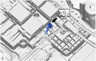
Procedure1
(c) Measure the resistance according to the value(s) in the table below.
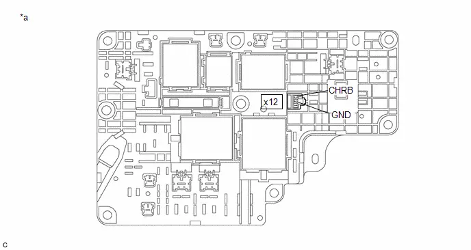
| *a | Component without harness connected (No. 1 Traction Battery Device Box Assembly) | - | - |
Standard Resistance:
 Click Location & Routing(x12) Click Connector(x12)
 | Tester Connection | Condition | Specified Condition | Result |
|---|---|---|---|
| x12-3 (CHRB) - x12-2 (GND) | -40 to 80°C (-40 to 176°F) | 20.6 to 40.8 Ω | Ω |
Post-procedure1
(d) Reconnect the No. 1 traction battery device box assembly connector.
| OK |

| CHECK FOR INTERMITTENT PROBLEMS |
| NG |

| REPLACE NO. 1 TRACTION BATTERY DEVICE BOX ASSEMBLY |
Hybrid/EV Battery Charging System Negative Contactor Control Circuit Short to Ground (P0D1111)
DESCRIPTION
Refer to the description for DTC P0D0A11.
Click here

| DTC No. | Detection Item | DTC Detection Condition | Trouble Area | MIL | Warning Indicate | DTC Output from | Priority | Note |
|---|---|---|---|---|---|---|---|---|
| P0D1111 | Hybrid/EV Battery Charging System Negative Contactor Control Circuit Short to Ground | Short to ground in the CHRG circuit: Primary circuit of CHR (-) is malfunctioning. (1 trip detection logic) |
| Comes on | Master Warning: Comes on | HV Battery | A | SAE Code: P0D13 |
MONITOR DESCRIPTION
If the battery ECU assembly detects a malfunction of its HV battery charging system negative contactor control circuit (CHRG), the battery ECU assembly illuminates the MIL and stores a DTC.
MONITOR STRATEGY
| Related DTCs | P0D13 (INF P0D1111): Battery Charging System Negative Contactor Control Circuit |
| Required sensors/components | Charge relay |
| Frequency of operation | Continuous |
| Duration | TMC's intellectual property |
| MIL operation | Immediately |
| Sequence of operation | None |
TYPICAL ENABLING CONDITIONS
| The monitor will run whenever the following DTCs are not stored | TMC's intellectual property |
| Other conditions belong to TMC's intellectual property | - |
TYPICAL MALFUNCTION THRESHOLDS
| TMC's intellectual property | - |
COMPONENT OPERATING RANGE
| Battery ECU assembly | DTC P0D13 (INF P0D1111) is not detected |
CONFIRMATION DRIVING PATTERN
HINT:
-
After repair has been completed, clear the DTC and then check that the Toyota Prius vehicle has returned to normal by performing the following All Readiness check procedure.
Click here

-
When clearing the permanent DTCs, refer to the "CLEAR PERMANENT DTC" procedure.
Click here

- Clear the DTCs (even if no DTCs are stored, perform the clear DTC procedure).
- Enter the following menus: Powertrain / HV Battery / Data List.[*1]
- Check that "Hybrid/EV Battery SOC" shows 70% or less.[*2]
- Turn the ignition switch off and wait for 2 minutes or more.[*3]
-
Connect the electric Toyota Prius vehicle charger cable assembly, plug-in charge the vehicle for at least 5 seconds.[*4]
HINT:
[*1] to [*4]: Normal judgment procedure.
The normal judgment procedure is used to complete DTC judgment and also used when clearing permanent DTCs.
- Enter the following menus: Powertrain / HV Battery / Utility / All Readiness.
-
Check the DTC judgment result.
HINT:
- If the judgment result shows NORMAL, the system is normal.
- If the judgment result shows ABNORMAL, the system has a malfunction.
- If the judgment result shows INCOMPLETE or N/A, perform the normal judgment procedure again.
WIRING DIAGRAM
Refer to the wiring diagram for DTC P0D0A11.
Click here

CAUTION / NOTICE / HINT
CAUTION:
Refer to the precautions before inspecting high voltage circuit.
Click here

NOTICE:
-
After the ignition switch is turned off, there may be a waiting time before disconnecting the auxiliary negative (-) battery terminal.
Click here

-
When disconnecting and reconnecting the auxiliary battery.
HINT:
When disconnecting and reconnecting the auxiliary battery, there is an automatic learning function that completes learning when the respective system is used.
Click here

PROCEDURE
| 1. | CHECK CONNECTOR CONNECTION CONDITION (BATTERY ECU ASSEMBLY) |
Click here

| NG |

| CONNECT SECURELY |
|

| 2. | CHECK HARNESS AND CONNECTOR (BATTERY ECU ASSEMBLY - BODY GROUND) |
CAUTION:
Be sure to wear insulated gloves and protective goggles.
Pre-procedure1
(a) Check that the service plug grip is not installed.
NOTICE:
After removing the service plug grip, do not turn the ignition switch to ON (READY), unless instructed by the repair manual because this may cause a malfunction.
| (b) Disconnect the battery ECU assembly connector. NOTICE: Before disconnecting the connector, check that it is not loose or disconnected. |
|

Procedure1
(c) Measure the resistance according to the value(s) in the tables below.
Standard Resistance:
 Click Location & Routing(x4) Click Connector(x4)
 | Tester Connection | Condition | Specified Condition | Result |
|---|---|---|---|
| x4-6 (CHRG) - Body ground | Ignition switch off | 20.6 to 40.8 Ω | Ω |
Post-procedure1
(d) Reconnect the battery ECU assembly connector.
| OK |

| REPLACE BATTERY ECU ASSEMBLY |
|

| 3. | CHECK CONNECTOR CONNECTION CONDITION (NO. 1 TRACTION BATTERY DEVICE BOX ASSEMBLY) |
CAUTION:
Be sure to wear insulated gloves and protective goggles.
Pre-procedure1
(a) Check that the service plug grip is not installed.
NOTICE:
After removing the service plug grip, do not turn the ignition switch to ON (READY), unless instructed by the repair manual because this may cause a malfunction.
Procedure1
| (b) Check the connections of the No. 1 traction battery device box assembly. HINT: Click here
OK: The connector is connected securely and there are no contact problems. Result:
|
|

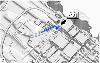
Post-procedure1
(c) None
| NG |

| CONNECT SECURELY |
|

| 4. | CHECK HARNESS AND CONNECTOR (BATTERY ECU ASSEMBLY - NO. 1 TRACTION BATTERY DEVICE BOX ASSEMBLY) |
CAUTION:
Be sure to wear insulated gloves and protective goggles.
Pre-procedure1
(a) Check that the service plug grip is not installed.
NOTICE:
After removing the service plug grip, do not turn the ignition switch to ON (READY), unless instructed by the repair manual because this may cause a malfunction.
| (b) Disconnect the battery ECU assembly connector. NOTICE: Before disconnecting the connector, check that it is not loose or disconnected. |
|

| (c) Disconnect the No. 1 traction battery device box assembly connector. NOTICE: Before disconnecting the connector, check that it is not loose or disconnected. |
|

Procedure1
(d) Measure the resistance according to the value(s) in the tables below.
Standard Resistance:
 Click Location & Routing(x13,x4) Click Connector(x13) Click Connector(x4)
 | Tester Connection | Condition | Specified Condition | Result |
|---|---|---|---|
| x13-1 (CHRG) and x4-6 (CHRG) - Body ground and other terminals | Ignition switch off | 10 kΩ or higher | kΩ |
Post-procedure1
(e) Reconnect the No. 1 traction battery device box assembly connector.
(f) Reconnect the battery ECU assembly connector.
| OK |

| REPLACE NO. 1 TRACTION BATTERY DEVICE BOX ASSEMBLY |
| NG |

| REPAIR OR REPLACE HARNESS OR CONNECTOR |
Hybrid/EV Battery Charging System Negative Contactor Control Circuit Short to Auxiliary Battery or Open (P0D1115)
DESCRIPTION
Refer to the description for DTC P0D0A11.
Click here

| DTC No. | Detection Item | DTC Detection Condition | Trouble Area | MIL | Warning Indicate | DTC Output from | Priority | Note |
|---|---|---|---|---|---|---|---|---|
| P0D1115 | Hybrid/EV Battery Charging System Negative Contactor Control Circuit Short to Auxiliary Battery or Open | Open or short to B in CHRG circuit: Primary circuit of CHR (-) is malfunctioning. (1 trip detection logic) |
| Comes on | Master Warning: Comes on | HV Battery | A | SAE Code: P0D14 |
MONITOR DESCRIPTION
If the battery ECU assembly detects a malfunction of its HV battery charging system negative contactor control circuit (CHRG), the battery ECU assembly illuminates the MIL and stores a DTC.
MONITOR STRATEGY
| Related DTCs | P0D14 (INF P0D1115): Battery Charging System Negative Contactor Control Circuit |
| Required sensors/components | Charge relay |
| Frequency of operation | Continuous |
| Duration | TMC's intellectual property |
| MIL operation | Immediately |
| Sequence of operation | None |
TYPICAL ENABLING CONDITIONS
| The monitor will run whenever the following DTCs are not stored | TMC's intellectual property |
| Other conditions belong to TMC's intellectual property | - |
TYPICAL MALFUNCTION THRESHOLDS
| TMC's intellectual property | - |
COMPONENT OPERATING RANGE
| Battery ECU assembly | DTC P0D14 (INF P0D1115) is not detected |
CONFIRMATION DRIVING PATTERN
HINT:
-
After repair has been completed, clear the DTC and then check that the Toyota Prius vehicle has returned to normal by performing the following All Readiness check procedure.
Click here

-
When clearing the permanent DTCs, refer to the "CLEAR PERMANENT DTC" procedure.
Click here

- Clear the DTCs (even if no DTCs are stored, perform the clear DTC procedure).
- Turn the ignition switch off and wait for 2 minutes or more.
-
Turn the ignition switch to ON and wait for 5 seconds or more.[*1]
HINT:
[*1]: Normal judgment procedure.
The normal judgment procedure is used to complete DTC judgment and also used when clearing permanent DTCs.
- Enter the following menus: Powertrain / HV Battery / Utility / All Readiness.
-
Check the DTC judgment result.
HINT:
- If the judgment result shows NORMAL, the system is normal.
- If the judgment result shows ABNORMAL, the system has a malfunction.
- If the judgment result shows INCOMPLETE or N/A, perform the normal judgment procedure again.
WIRING DIAGRAM
Refer to the wiring diagram for DTC P0D0A11.
Click here

CAUTION / NOTICE / HINT
CAUTION:
Refer to the precautions before inspecting high voltage circuit.
Click here

NOTICE:
-
After the ignition switch is turned off, there may be a waiting time before disconnecting the auxiliary negative (-) battery terminal.
Click here

-
When disconnecting and reconnecting the auxiliary battery.
HINT:
When disconnecting and reconnecting the auxiliary battery, there is an automatic learning function that completes learning when the respective system is used.
Click here

PROCEDURE
| 1. | READ VALUE USING GTS (AC CHARGING NEGATIVE RELAY STATUS) |
Pre-procedure1
(a) None
Procedure1
(b) Read the Data List.
Powertrain > HV Battery > Data List| Tester Display |
|---|
| AC Charging Negative Relay Status |
Standard:
| Tester Display | Condition | Specified Condition |
|---|---|---|
| AC Charging Negative Relay Status | Ignition switch ON | OFF |
| Result | Proceed to |
|---|---|
| The value of AC Charging Negative Relay Status is OFF | A |
| The value of AC Charging Negative Relay Status is ON | B |
Post-procedure1
(c) Turn the ignition switch off.
| B |

| GO TO STEP 4 |
|

| 2. | CHECK CONNECTOR CONNECTION CONDITION (BATTERY ECU ASSEMBLY) |
Click here

| NG |

| CONNECT SECURELY |
|

| 3. | CHECK CONNECTOR CONNECTION CONDITION (NO. 1 TRACTION BATTERY DEVICE BOX ASSEMBLY) |
Click here

| OK |

| CHECK FOR INTERMITTENT PROBLEMS |
| NG |

| CONNECT SECURELY |
| 4. | CHECK CONNECTOR CONNECTION CONDITION (BATTERY ECU ASSEMBLY) |
Click here

| NG |

| CONNECT SECURELY |
|

| 5. | CHECK HARNESS AND CONNECTOR (CHRG VOLTAGE) |
CAUTION:
Be sure to wear insulated gloves and protective goggles.
Pre-procedure1
(a) Check that the service plug grip is not installed.
NOTICE:
After removing the service plug grip, do not turn the ignition switch to ON (READY), unless instructed by the repair manual because this may cause a malfunction.
(b) Connect the SST.
HINT:
Click here

| (c) Disconnect the battery ECU assembly connector. NOTICE: Before disconnecting the connector, check that it is not loose or disconnected. |
|

(d) Connect the cable to the negative (-) auxiliary battery terminal.
(e) Turn the ignition switch to ON.
Procedure1
(f) Measure the voltage according to the value(s) in the table below.
Standard Voltage:
 Click Location & Routing(x4) Click Connector(x4)
 | Tester Connection | Condition | Specified Condition | Result |
|---|---|---|---|
| x4-6 (CHRG) - Body ground | Ignition switch ON | Below 1 V | V |
NOTICE:
- Turning the ignition switch to ON with the service plug grip removed causes other DTCs to be stored. Clear the DTCs after performing this inspection.
- If the ignition switch is turned to ON with the connectors disconnected, other DTCs will be stored. Be sure to clear the DTCs after the inspection.
Post-procedure1
(g) Turn the ignition switch off.
(h) Disconnect the cable from the negative (-) auxiliary battery terminal.
(i) Reconnect the battery ECU assembly connector.
(j) Disconnect the SST.
| OK |

| REPLACE BATTERY ECU ASSEMBLY |
|

| 6. | CHECK HARNESS AND CONNECTOR (BATTERY ECU ASSEMBLY - BODY GROUND) |
Click here

| NG |

| GO TO STEP 9 |
|

| 7. | CHECK CONNECTOR CONNECTION CONDITION (NO. 1 TRACTION BATTERY DEVICE BOX ASSEMBLY) |
Click here

| NG |

| CONNECT SECURELY |
|

| 8. | CHECK HARNESS AND CONNECTOR (SHORT TO POWER SUPPLY WIRES) |
CAUTION:
Be sure to wear insulated gloves and protective goggles.
Pre-procedure1
(a) Check that the service plug grip is not installed.
NOTICE:
After removing the service plug grip, do not turn the ignition switch to ON (READY), unless instructed by the repair manual because this may cause a malfunction.
(b) Connect the SST.
HINT:
Click here

| (c) Disconnect the battery ECU assembly connector. NOTICE: Before disconnecting the connector, check that it is not loose or disconnected. |
|

| (d) Disconnect the No. 1 traction battery device box assembly connector. NOTICE: Before disconnecting the connector, check that it is not loose or disconnected. |
|

Procedure1
(e) Measure the resistance according to the value(s) in the tables below.
Standard Resistance (Check for Open):
 Click Location & Routing(x13,x4) Click Connector(x13) Click Connector(x4)
 | Tester Connection | Condition | Specified Condition | Result |
|---|---|---|---|
| x13-1 (CHRG) - x4-6 (CHRG) | Ignition switch off | Below 1 Ω | Ω |
Standard Resistance (Check for Short):
 Click Location & Routing(x13,x4) Click Connector(x13) Click Connector(x4)
 | Tester Connection | Condition | Specified Condition | Result |
|---|---|---|---|
| x13-1 (CHRG) and x4-6 (CHRG) - Body ground and other terminals | Ignition switch off | 10 kΩ or higher | kΩ |
Pre-procedure2
(f) Connect the cable to the negative (-) auxiliary battery terminal.
(g) Turn the ignition switch to ON.
Procedure2
(h) Measure the voltage according to the value(s) in the table below.
Standard Voltage:
 Click Location & Routing(x13,x4) Click Connector(x13) Click Connector(x4)
 | Tester Connection | Condition | Specified Condition | Result |
|---|---|---|---|
| x13-1 (CHRG) and x4-6 (CHRG) - Body ground | Ignition switch ON | Below 1 V | V |
NOTICE:
- Turning the ignition switch to ON with the service plug grip removed causes other DTCs to be stored. Clear the DTCs after performing this inspection.
- If the ignition switch is turned to ON with the connectors disconnected, other DTCs will be stored. Be sure to clear the DTCs after the inspection.
Post-procedure1
(i) Turn the ignition switch off.
(j) Disconnect the cable from the negative (-) auxiliary battery terminal.
(k) Reconnect the No. 1 traction battery device box assembly connector.
(l) Reconnect the battery ECU assembly connector.
(m) Disconnect the SST.
| OK |

| REPLACE BATTERY ECU ASSEMBLY |
| NG |

| REPAIR OR REPLACE HARNESS OR CONNECTOR |
| 9. | CHECK CONNECTOR CONNECTION CONDITION (NO. 1 TRACTION BATTERY DEVICE BOX ASSEMBLY) |
Click here

| NG |

| CONNECT SECURELY |
|

| 10. | CHECK HARNESS AND CONNECTOR (BATTERY ECU ASSEMBLY - NO. 1 TRACTION BATTERY DEVICE BOX ASSEMBLY) |
CAUTION:
Be sure to wear insulated gloves and protective goggles.
Pre-procedure1
(a) Check that the service plug grip is not installed.
NOTICE:
After removing the service plug grip, do not turn the ignition switch to ON (READY), unless instructed by the repair manual because this may cause a malfunction.
| (b) Disconnect the battery ECU assembly connector. NOTICE: Before disconnecting the connector, check that it is not loose or disconnected. |
|

| (c) Disconnect the No. 1 traction battery device box assembly connector. NOTICE: Before disconnecting the connector, check that it is not loose or disconnected. |
|

Procedure1
(d) Measure the resistance according to the value(s) in the tables below.
Standard Resistance (Check for Open):
 Click Location & Routing(x13,x4) Click Connector(x13) Click Connector(x4)
 | Tester Connection | Condition | Specified Condition | Result |
|---|---|---|---|
| x13-1 (CHRG) - x4-6 (CHRG) | Ignition switch off | Below 1 Ω | Ω |
Standard Resistance (Check for Short):
 Click Location & Routing(x13,x4) Click Connector(x13) Click Connector(x4)
 | Tester Connection | Condition | Specified Condition | Result |
|---|---|---|---|
| x13-1 (CHRG) and x4-6 (CHRG) - Body ground and other terminals | Ignition switch off | 10 kΩ or higher | kΩ |
Post-procedure1
(e) Reconnect the No. 1 traction battery device box assembly connector.
(f) Reconnect the battery ECU assembly connector.
| NG |

| REPAIR OR REPLACE HARNESS OR CONNECTOR |
|

| 11. | CHECK HARNESS AND CONNECTOR (NO. 1 TRACTION BATTERY DEVICE BOX ASSEMBLY - BODY GROUND) |
CAUTION:
Be sure to wear insulated gloves and protective goggles.
Pre-procedure1
(a) Check that the service plug grip is not installed.
NOTICE:
After removing the service plug grip, do not turn the ignition switch to ON (READY), unless instructed by the repair manual because this may cause a malfunction.
| (b) Disconnect the No. 1 traction battery device box assembly connector. NOTICE: Before disconnecting the connector, check that it is not loose or disconnected. |
|

Procedure1
(c) Measure the resistance according to the value(s) in the tables below.
Standard Resistance:
 Click Location & Routing(x13) Click Connector(x13)
 | Tester Connection | Condition | Specified Condition | Result |
|---|---|---|---|
| x13-3 (GND8) - Body ground | Ignition switch off | Below 1 Ω | Ω |
Post-procedure1
(d) Reconnect the No. 1 traction battery device box assembly connector.
| NG |

| REPAIR OR REPLACE HARNESS OR CONNECTOR |
|

| 12. | INSPECT NO. 1 TRACTION BATTERY DEVICE BOX ASSEMBLY (CHRG) |
CAUTION:
Be sure to wear insulated gloves and protective goggles.
Pre-procedure1
(a) Check that the service plug grip is not installed.
NOTICE:
After removing the service plug grip, do not turn the ignition switch to ON (READY), unless instructed by the repair manual because this may cause a malfunction.
| (b) Disconnect the No. 1 traction battery device box assembly connector. NOTICE: Before disconnecting the connector, check that it is not loose or disconnected. |
|

Procedure1
(c) Measure the resistance according to the value(s) in the table below.
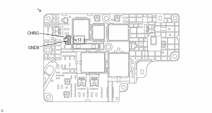
| *a | Component without harness connected (No. 1 Traction Battery Device Box Assembly) | - | - |
Standard Resistance:
 Click Location & Routing(x13) Click Connector(x13)
 | Tester Connection | Condition | Specified Condition | Result |
|---|---|---|---|
| x13-1 (CHRG) - x13-3 (GND8) | -40 to 80°C (-40 to 176°F) | 20.6 to 40.8 Ω | Ω |
Post-procedure1
(d) Reconnect the No. 2 traction battery device box assembly connector.
| OK |

| CHECK FOR INTERMITTENT PROBLEMS |
| NG |

| REPLACE NO. 1 TRACTION BATTERY DEVICE BOX ASSEMBLY |
Hybrid/EV Battery Pack Coolant Control Valve "B" Control Circuit Low Circuit Current Below Threshold (P0D1A18,P0D1A19,P1F6900)
DESCRIPTION
| DTC No. | Detection Item | DTC Detection Condition | Trouble Area | MIL | Warning Indicate | DTC Output from | Priority | Note |
|---|---|---|---|---|---|---|---|---|
| P0D1A18 | Hybrid/EV Battery Pack Coolant Control Valve "B" Control Circuit Low Circuit Current Below Threshold | When the motor is being operated, there is an open or short in the magnet valve (No. 1 traction battery cooler tube) circuit or the magnet valve (No. 1 traction battery cooler tube) is overheating (1 trip detection logic) |
| Comes on | Master Warning: Comes on | HV Battery | A | SAE Code: P0D1D |
| P0D1A19 | Hybrid/EV Battery Pack Coolant Control Valve "B" Control Circuit High Circuit Current Above Threshold | When the motor is being operated, there is an open or short in the magnet valve (No. 1 traction battery cooler tube) circuit or the magnet valve (No. 1 traction battery cooler tube) is overheating (1 trip detection logic) |
| Comes on | Master Warning: Comes on | HV Battery | A | SAE Code: P0D1E |
| P1F6900 | Hybrid/EV Battery Pack Coolant Control Valve "B" Monitor Performance | When the motor is being operated, there is an open or short in the magnet valve (No. 1 traction battery cooler tube) circuit or the magnet valve (No. 1 traction battery cooler tube) is overheating (1 trip detection logic) |
| Comes on | Master Warning: Comes on | HV Battery | A | SAE Code: P1F69 |
MONITOR DESCRIPTION
If the battery ECU assembly detects a malfunction in a magnet valve, the battery ECU assembly will illuminate the MIL and store a DTC.
MONITOR STRATEGY
| Related DTCs | P0D1D (INF P0D1A18): Hybrid Battery Pack Coolant Control Valve 2 (Battery Refrigerant Electric Expansion Valve) Range check (Low current) P0D1E (INF P0D1A19): Hybrid Battery Pack Coolant Control Valve 2 (Battery Refrigerant Electric Expansion Valve) Range check (High current) P1F69 (INF P1F6900): Hybrid Battery Pack Coolant Control Valve 2 (Battery Refrigerant Electric Expansion Valve) Performance |
| Required sensors/components | Magnet valve |
| Frequency of operation | Continuous |
| Duration | TMC's intellectual property |
| MIL operation | Immediately |
| Sequence of operation | None |
TYPICAL ENABLING CONDITIONS
| The monitor will run whenever the following DTCs are not stored | TMC's intellectual property |
| Other conditions belong to TMC's intellectual property | - |
TYPICAL MALFUNCTION THRESHOLDS
| TMC's intellectual property | - |
COMPONENT OPERATING RANGE
| Battery ECU assembly | DTC P0D1D (INF P0D1A18) is not detected DTC P0D1E (INF P0D1A19) is not detected DTC P1F69 (INF P1F6900) is not detected |
CONFIRMATION DRIVING PATTERN
HINT:
-
After repair has been completed, clear the DTC and then check that the Toyota Prius vehicle has returned to normal by performing the following All Readiness check procedure.
Click here

-
When clearing the permanent DTCs, refer to the "CLEAR PERMANENT DTC" procedure.
Click here

- Clear the DTCs (even if no DTCs are stored, perform the clear DTC procedure).
- Turn the ignition switch off and wait for 2 minutes or more.
-
Drive the Toyota Prius vehicle on urban roads for approximately 10 minutes.[*1]
HINT:
[*1]: Normal judgment procedure.
The normal judgment procedure is used to complete DTC judgment and also used when clearing permanent DTCs.
- Enter the following menus: Powertrain / HV Battery / Utility / All Readiness.
-
Check the DTC judgment result.
HINT:
- If the judgment result shows NORMAL, the system is normal.
- If the judgment result shows ABNORMAL, the system has a malfunction.
- If the judgment result shows INCOMPLETE or N/A, perform the normal judgment procedure again.
WIRING DIAGRAM

CAUTION / NOTICE / HINT
CAUTION:
Refer to the precautions before inspecting high voltage circuit.
Click here

NOTICE:
-
After the ignition switch is turned off, there may be a waiting time before disconnecting the auxiliary negative (-) battery terminal.
Click here

-
When disconnecting and reconnecting the auxiliary battery.
HINT:
When disconnecting and reconnecting the auxiliary battery, there is an automatic learning function that completes learning when the respective system is used.
Click here

PROCEDURE
| 1. | CHECK HARNESS AND CONNECTOR (MAGNET VALVE (NO. 1 TRACTION BATTERY COOLER TUBE) - BATTERY ECU ASSEMBLY) |
CAUTION:
Be sure to wear insulated gloves and protective goggles.
Pre-procedure1
(a) Check that the service plug grip is not installed.
NOTICE:
After removing the service plug grip, do not turn the ignition switch to ON (READY), unless instructed by the repair manual because this may cause a malfunction.
| (b) Disconnect the Battery ECU assembly connector. NOTICE: Before disconnecting the connector, check that it is not loose or disconnected. |
|

| (c) Disconnect the magnet valve (No. 1 traction battery cooler tube) connector . NOTICE: Before disconnecting the connector, check that it is not loose or disconnected. |
|

Procedure1
(d) Measure the resistance according to the value(s) in the table below.
Standard Resistance:
 Click Location & Routing(x8,x4) Click Connector(x8) Click Connector(x4)
 | Tester Connection | Condition | Specified Condition | Result |
|---|---|---|---|
| x8-4 (HPR ) - x4-20 (SMA0) | Ignition switch off | Below 1 Ω | Ω |
| x8-1 (HPR-) - x4-21 (SMB0) | Ignition switch off | Below 1 Ω | Ω |
| x8-5 (HPL ) - x4-22 (SMC0) | Ignition switch off | Below 1 Ω | Ω |
| x8-2 (HPL-) - x4-23 (SMD0) | Ignition switch off | Below 1 Ω | Ω |
| x8-4 (HPR ) or x4-20 (SMA0) - Body ground and other terminals | Ignition switch off | 10 kΩ or higher | kΩ |
| x8-1 (HPR-) or x4-21 (SMB0) - Body ground and other terminals | Ignition switch off | 10 kΩ or higher | kΩ |
| x8-5 (HPL ) or x4-22 (SMC0) - Body ground and other terminals | Ignition switch off | 10 kΩ or higher | kΩ |
| x8-2 (HPL-) or x4-23 (SMD0) - Body ground and other terminals | Ignition switch off | 10 kΩ or higher | kΩ |
Post-procedure1
(e) Reconnect the magnet valve (No. 1 traction battery cooler tube) connector.
(f) Reconnect the battery ECU assembly connector.
| NG |

| REPAIR OR REPLACE HARNESS OR CONNECTOR |
|

| 2. | INSPECT MAGNET VALVE (NO. 1 TRACTION BATTERY COOLER TUBE) |
CAUTION:
Be sure to wear insulated gloves and protective goggles.
Pre-procedure1
(a) Check that the service plug grip is not installed.
NOTICE:
After removing the service plug grip, do not turn the ignition switch to ON (READY), unless instructed by the repair manual because this may cause a malfunction.
| (b) Disconnect the magnet valve (No. 1 traction battery cooler tube) connector. NOTICE: Before disconnecting the connector, check that it is not loose or disconnected. |
|

Procedure1
| (c) Measure the resistance according to the value(s) in the table below. Standard Resistance:  Click Location & Routing(x8) Click Connector(x8) Click Location & Routing(x8) Click Connector(x8)
Result:
|
|

Post-procedure1
(d) Reconnect the magnet valve (No. 1 traction battery cooler tube) connector.
| NG |

| REPLACE NO. 1 TRACTION BATTERY COOLER TUBE |
|

| 3. | CHECK BATTERY ECU ASSEMBLY (OUTPUT WAVEFORM) |
CAUTION:
Be sure to wear insulated gloves and protective goggles.
Pre-procedure1
(a) Check that the service plug grip is not installed.
NOTICE:
After removing the service plug grip, do not turn the ignition switch to ON (READY), unless instructed by the repair manual because this may cause a malfunction.
(b) Connect the SST.
HINT:
Click here

(c) Connect the cable to the negative (-) auxiliary battery terminal.
Procedure1
(d) Check the output waveform.
| (1) Connect an oscilloscope to terminal. |
|

(2) Enter the following menus.
Powertrain > HV Battery > Active Test| Tester Display |
|---|
| Hybrid/EV Battery Refrigerant Cooling Valve |
| (3) Check the signal waveform according to the condition(s) in the table below.
NOTICE: Turning the ignition switch to ON with the service plug grip removed causes other DTCs to be stored. Clear the DTCs after performing this inspection. |
|
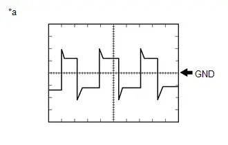
| Result | Proceed to |
|---|---|
| Normal (The pulse output of waveform 1) | A |
| No pulse generation | B |
Post-procedure1
(e) Turn the ignition switch off.
(f) Disconnect the cable from the negative (-) auxiliary battery terminal.
(g) Disconnect the SST.
| A |

| REPLACE NO. 1 TRACTION BATTERY COOLER TUBE |
| B |

| REPLACE BATTERY ECU ASSEMBLY |
Hybrid/EV Battery Pack Coolant Control Valve "B" Performance/Stuck Off Actuator Stuck (P0D1A71)
DTC SUMMARY
MALFUNCTION DESCRIPTION
The system determines that there is a deviation in characteristics for the magnet valve (No. 1 traction battery cooler tube) in the HV battery refrigerant cooling system and prevents the HV battery temperature from rising excessively.
DESCRIPTION
| DTC No. | Detection Item | DTC Detection Condition | Trouble Area | MIL | Warning Indicate | DTC Output from | Priority | Note |
|---|---|---|---|---|---|---|---|---|
| P0D1A71 | Hybrid/EV Battery Pack Coolant Control Valve "B" Performance/Stuck Off Actuator Stuck | Detected when either of the following conditions is satisfied within the specified time from when HV battery cooling started (2 trip detection logic) Open malfunction detected
Close malfunction detected
|
| Comes on | Master Warning: Comes on | HV Battery | A | SAE Code: P0D1B |
MONITOR DESCRIPTION
Within the specified time from when HV battery cooling starts, if it is detected that the command value sent to the magnet valve is a close command and the change in the refrigerant inlet and outlet temperature is higher than the specified value, or the command value sent to the magnet valve is an open command and the change in the refrigerant inlet temperature is lower than the specified value, the battery ECU assembly illuminates the MIL and stores a DTC.
MONITOR STRATEGY
| Related DTCs | P0D1B (INF P0D1A71): Hybrid/EV Battery Pack Coolant Control Valve "B" Performance/Stuck Off |
| Required sensors/components | Magnet valve, Air Conditioning Thermistor |
| Frequency of operation | Continuous |
| Duration | TMC's intellectual property |
| MIL operation | 2 driving cycles |
| Sequence of operation | None |
TYPICAL ENABLING CONDITIONS
| The monitor will run whenever the following DTCs are not stored | TMC's intellectual property |
| Other conditions belong to TMC's intellectual property | - |
TYPICAL MALFUNCTION THRESHOLDS
| TMC's intellectual property | - |
COMPONENT OPERATING RANGE
| Battery ECU assembly | DTC P0D1B (INF P0D1A71) is not detected |
CONFIRMATION DRIVING PATTERN
HINT:
-
After repair has been completed, clear the DTC and then check that the Toyota Prius vehicle has returned to normal by performing the following All Readiness check procedure.
Click here

-
When clearing the permanent DTCs, refer to the "CLEAR PERMANENT DTC" procedure.
Click here

- Clear the DTCs (even if no DTCs are stored, perform the clear DTC procedure).
- Turn the ignition switch off and wait for 2 minutes or more.
- Enter the following menus: Powertrain / HV Battery / Active Test / Hybrid/EV Battery Refrigerant Cooling Control / Data List / Hybrid/EV Battery Temperature 1 to 15, Hybrid/EV Battery Refrigerant Temperature (Duct Inlet 1), Hybrid/EV Battery Refrigerant Temperature (Duct Outlet 1).[*1]
-
Check that the value of Data List item "Hybrid/EV Battery Temperature 1 to 15" is a minimum of 11°C (52°F) or more, and the value of Data List item "Hybrid/EV Battery Refrigerant Temperature (Duct Inlet 1)" and "Hybrid/EV Battery Refrigerant Temperature (Duct Outlet 1)" is 0°C (32°F) or more.[*2] Conditions for performing "Hybrid/EV Battery Refrigerant Cooling Control" Active Test
HINT:
The HV battery minimum temperature must be 11°C (52°F) and the refrigerant temperature inside the HV battery must be 0°C (32°F) or higher.
If the above conditions are not established, perform the "Hybrid/EV Battery Heater Relay" Active Test in an environment with an ambient temperature of 5°C (41°F) or higher and increase the HV battery temperature.
In consideration of the temperature drop after the heater stops, increase the value of Data List item "Hybrid/EV Battery Temperature 1 to 15" to a minimum of 12°C (54°F) or more, and the value of Data List item "Hybrid/EV Battery Refrigerant Temperature (Duct Inlet 1)" and "Hybrid/EV Battery Refrigerant Temperature (Duct Outlet 1)" to 1°C (34°F) or more.
(At an ambient temperature of 5°C (41°F), "Hybrid/EV Battery Heater Relay" will need to be performed for approximately 5 hours.)
-
Set the Toyota Prius vehicle to the following conditions.[*3]
Item
Condition
A/C Switch
ON
Blower Speed
HI
Set Temperature
- MAX COLD when the ambient temperature is 25°C (77°F) or higher
- MAX HOT when the ambient temperature is less than 25°C (77°F)
HINT:
If the ambient temperature is from 25°C (77°F) to 30°C (86°F), perform the "Hybrid/EV Battery Refrigerant Cooling Control" Active Test within 1 minute from setting the above conditions.
-
Check that the value of Data List item "Hybrid/EV Battery Temperature 1 to 15" is a minimum of 11°C (52°F) or more, and the value of Data List item "Hybrid/EV Battery Refrigerant Temperature (Duct Inlet 1)" and "Hybrid/EV Battery Refrigerant Temperature (Duct Outlet 1)" is 0°C (32°F) or more.[*4]
HINT:
Setting "A/C Switch" to "ON" and "Blower Speed" to "HI" in the Toyota Prius vehicle may cause the refrigerant temperature inside the HV battery to drop.
If the temperature has dropped lower than the conditions for performing the "Hybrid/EV Battery Refrigerant Cooling Control" Active Test, perform the "Hybrid/EV Battery Heater Relay" Active Test in an environment with an ambient temperature of 5°C (41°F) or higher and increase the temperature.
- Perform the "Hybrid/EV Battery Refrigerant Cooling Control" Active Test for 14 minutes.[*5]
- Turn the ignition switch off and wait for 1 minute or more.[*6]
- Enter the following menus: Powertrain / HV Battery / Active Test / Hybrid/EV Battery Refrigerant Cooling Control / Data List / Hybrid/EV Battery Temperature 1 to 15, Hybrid/EV Battery Refrigerant Temperature (Duct Inlet 1), Hybrid/EV Battery Refrigerant Temperature (Duct Outlet 1).[*7]
-
Check that the value of Data List item "Hybrid/EV Battery Temperature 1 to 15" is a minimum of 11°C (52°F) or more, and the value of Data List item "Hybrid/EV Battery Refrigerant Temperature (Duct Inlet 1)" and "Hybrid/EV Battery Refrigerant Temperature (Duct Outlet 1)" is 0°C (32°F) or more.[*8] Conditions for performing "Hybrid/EV Battery Refrigerant Cooling Control" Active Test
HINT:
The HV battery minimum temperature must be 11°C (52°F) and the refrigerant temperature inside the HV battery must be 0°C (32°F) or higher.
If the above conditions are not established, perform the "Hybrid/EV Battery Heater Relay" Active Test in an environment with an ambient temperature of 5°C (41°F) or higher and increase the HV battery temperature.
In consideration of the temperature drop after the heater stops, increase the value of Data List item "Hybrid/EV Battery Temperature 1 to 15" to a minimum of 12°C (54°F) or more, and the value of Data List item "Hybrid/EV Battery Refrigerant Temperature (Duct Inlet 1)" and "Hybrid/EV Battery Refrigerant Temperature (Duct Outlet 1)" to 1°C (34°F) or more.
(At an ambient temperature of 5°C (41°F), "Hybrid/EV Battery Heater Relay" will need to be performed for approximately 5 hours.)
-
Set the Toyota Prius vehicle to the following conditions.[*9]
Item
Condition
A/C Switch
ON
Blower Speed
HI
Set Temperature
- MAX COLD when the ambient temperature is 25°C (77°F) or higher
- MAX HOT when the ambient temperature is less than 25°C (77°F)
HINT:
If the ambient temperature is from 25°C (77°F) to 30°C (86°F), perform the "Hybrid/EV Battery Refrigerant Cooling Control" Active Test within 1 minute from setting the above conditions.
-
Check that the value of Data List item "Hybrid/EV Battery Temperature 1 to 15" is a minimum of 11°C (52°F) or more, and the value of Data List item "Hybrid/EV Battery Refrigerant Temperature (Duct Inlet 1)" and "Hybrid/EV Battery Refrigerant Temperature (Duct Outlet 1)" is 0°C (32°F) or more.[*10]
HINT:
Setting "A/C Switch" to "ON" and "Blower Speed" to "HI" in the Toyota Prius vehicle may cause the refrigerant temperature inside the HV battery to drop.
If the temperature has dropped lower than the conditions for performing the "Hybrid/EV Battery Refrigerant Cooling Control" Active Test, perform the "Hybrid/EV Battery Heater Relay" Active Test in an environment with an ambient temperature of 5°C (41°F) or higher and increase the temperature.
-
Perform the "Hybrid/EV Battery Refrigerant Cooling Control" Active Test for 14 minutes.[*11]
HINT:
[*1] to [*11]: Normal judgment procedure.
The normal judgment procedure is used to complete DTC judgment and also used when clearing permanent DTCs.
- Enter the following menus: Powertrain / HV Battery / Utility / All Readiness.
-
Check the DTC judgment result.
HINT:
- If the judgment result shows NORMAL, the system is normal.
- If the judgment result shows ABNORMAL, the system has a malfunction.
- If the judgment result shows INCOMPLETE or N/A, perform the normal judgment procedure again.
WIRING DIAGRAM
Refer to the wiring diagram for DTC P0D1A18.
Click here

CAUTION / NOTICE / HINT
CAUTION:
Refer to the precautions before inspecting high voltage circuit.
Click here

NOTICE:
-
After the ignition switch is turned off, there may be a waiting time before disconnecting the auxiliary negative (-) battery terminal.
Click here

-
When disconnecting and reconnecting the auxiliary battery.
HINT:
When disconnecting and reconnecting the auxiliary battery, there is an automatic learning function that completes learning when the respective system is used.
Click here

PROCEDURE
| 1. | CHECK DTC OUTPUT (HV BATTERY, HYBRID CONTROL, AIR CONDITIONER) |
Pre-procedure1
(a) None
Procedure1
(b) Check for DTCs.
Powertrain > HV Battery > Trouble Codes Powertrain > Hybrid Control > Trouble Codes Body Electrical > Air Conditioner > Trouble Codes| Result | Proceed to |
|---|---|
| "P0D1A71" only is output, or DTCs except the ones in the table below are also output. | A |
| DTCs of hybrid battery system in the table below are output. | B |
| DTCs of hybrid control system in the table below are output. | C |
| DTCs of air conditioning system in the table below are output. | D |
| Malfunction Content | System | Relevant DTC | |
|---|---|---|---|
| Air conditioner malfunction | Air conditioning system | B138571 | A/C Cooling Electric Expansion Valve Actuator Stuck |
| B3A0A71 | A/C Heating Electric Expansion Valve Actuator Stuck | ||
| P0EC971 | A/C Low Pressure Magnetic Valve Actuator Stuck | ||
| P05301C | Refrigerant Pressure Sensor Circuit Voltage Out of Range | ||
| P15017A | Hybrid/EV Battery Cooling Refrigerant Gas Fluid Leak or Seal Failure | ||
| P2D4496 | A/C Compressor Component Internal Failure | ||
| Microcomputer malfunction | Hybrid battery system | P060A47 | Hybrid/EV Battery Energy Control Module Monitoring Processor Watchdog / Safety MCU Failure |
| P060B49 | Hybrid/EV Battery Energy Control Module A/D Processing Internal Electronic Failure | ||
| P060687 | Hybrid/EV Battery Energy Control Module Processor to Monitoring Processor Missing Message | ||
| Hybrid control system | P0A1F94 | Hybrid/EV Battery Energy Control Module Unexpected Operation | |
Post-procedure1
(c) Turn the ignition switch off.
| B |

| GO TO DTC CHART (HYBRID BATTERY SYSTEM) |
| C |

| GO TO DTC CHART (HYBRID CONTROL SYSTEM) |
| D |

| GO TO DTC CHART (AIR CONDITIONING SYSTEM) |
|

| 2. | CHECK Toyota Prius Vehicle CONDITION |
Pre-procedure1
(a) Make sure that the front side of the radiator grille is not blocked with anything.
Procedure1
(b) Ask the customer if the front side of the radiator grille was blocked with anything.
| Result | Proceed to |
|---|---|
| Not blocked. | A |
| Is/was blocked. | B |
HINT:
If the radiator grille is blocked, the inverter coolant temperature will increase and this DTC may be stored.
Post-procedure1
(c) None
| B |

| IF EQUIPPED, EXPLAIN TO CUSTOMER THAT OPTIONAL COMPONENTS WILL BE REMOVED |
|

| 3. | INSPECT COOLING FAN |
Pre-procedure1
(a) None
Procedure1
(b) Perform the "Control the Engine Cooling Fan Duty Ratio" Active Test.
Powertrain > Engine > Active Test| Tester Display |
|---|
| Control the Engine Cooling Fan Duty Ratio |
OK:
| GTS Operation | Fan Operation |
|---|---|
| 30 - 100% | Cooling fan operates |
| 0% | Cooling fan stops |
| Result | Proceed to |
|---|---|
| Cooling fan operate | A |
| Cooling fan does not operate | B |
| Cooling fan do not stop |
Post-procedure1
(c) Turn the ignition switch off.
| B |

| GO TO COOLING FAN CIRCUIT |
|

| 4. | REFRIGERANT SHORTAGE CHECK USING GTS |
HINT:
Click here

| NG |

| GO TO STEP 8 |
|

| 5. | CHECK HARNESS AND CONNECTOR (MAGNET VALVE (NO. 1 TRACTION BATTERY COOLER TUBE) - BATTERY ECU ASSEMBLY) |
Click here

| NG |

| REPAIR OR REPLACE HARNESS OR CONNECTOR |
|

| 6. | INSPECT MAGNET VALVE (NO. 1 TRACTION BATTERY COOLER TUBE) |
Click here

| NG |

| REPLACE NO. 1 TRACTION BATTERY COOLER TUBE |
|

| 7. | CHECK BATTERY ECU ASSEMBLY (OUTPUT WAVEFORM) |
Click here

| Result | Proceed to |
|---|---|
| Normal (The pulse output of waveform 1) | A |
| No pulse generation | B |
| A |

| REPLACE NO. 1 TRACTION BATTERY COOLER TUBE |
| B |

| REPLACE BATTERY ECU ASSEMBLY |
| 8. | INSPECT FOR REFRIGERANT LEAK (AIR CONDITIONING SYSTEM) |
Click here

| NG |

| GO TO PROBLEM SYMPTOMS TABLE (AIR CONDITIONING SYSTEM) |
|

| 9. | INSPECT FOR REFRIGERANT LEAK (INLET SIDE OF HV SUPPLY BATTERY ASSEMBLY) |
Click here

| OK |

| CHECK AND REPLACE REFRIGERANT LEAK (HV SUPPLY BATTERY ASSEMBLY) |
| NG |

| GO TO PROBLEM SYMPTOMS TABLE (AIR CONDITIONING SYSTEM) |
Hybrid/EV Battery Energy Control Module Hybrid/EV Battery Monitor Performance (P0E2D00)
DESCRIPTION
The battery ECU assembly detects the voltage of each HV battery cell. The battery ECU assembly monitors its internal HV battery cell voltage detection circuits to detect malfunctions. If the battery ECU assembly detects a malfunction it will store this DTC.
| DTC No. | Detection Item | DTC Detection Condition | Trouble Area | MIL | Warning Indicate | DTC Output from | Priority | Note |
|---|---|---|---|---|---|---|---|---|
| P0E2D00 | Hybrid/EV Battery Energy Control Module Hybrid/EV Battery Monitor Performance | The battery ECU assembly detects a malfunction of its internal HV battery cell voltage detection circuits. (1 trip detection logic) |
| Comes on | Master Warning: Comes on | HV Battery | A | SAE Code: P0E2D |
MONITOR DESCRIPTION
The battery ECU assembly monitors its internal HV battery cell voltage detection circuits to detect malfunctions. If the battery ECU assembly detects a malfunction, it will illuminate the MIL and store a DTC.
MONITOR STRATEGY
| Related DTCs | P0E2D (INF P0E2D00): Internal control module Hybrid/EV battery monitor performance |
| Required sensors/components | Battery ECU assembly |
| Frequency of operation | Continuous |
| Duration | TMC's intellectual property |
| MIL operation | 1 driving cycle |
| Sequence of operation | None |
TYPICAL ENABLING CONDITIONS
| The monitor will run whenever the following DTCs are not stored | TMC's intellectual property |
| Other conditions belong to TMC's intellectual property | - |
TYPICAL MALFUNCTION THRESHOLDS
| TMC's intellectual property | - |
COMPONENT OPERATING RANGE
| Battery ECU assembly | DTC P0E2D (INF P0E2D00) is not detected |
CONFIRMATION DRIVING PATTERN
HINT:
-
After repair has been completed, clear the DTC and then check that the Toyota Prius vehicle has returned to normal by performing the following All Readiness check procedure.
Click here

-
When clearing the permanent DTCs, refer to the "CLEAR PERMANENT DTC" procedure.
Click here

- Clear the DTCs (even if no DTCs are stored, perform the clear DTC procedure).
- Turn the ignition switch off and wait for 2 minutes or more.
-
Turn the ignition switch to ON and wait for 10 seconds or more.[*1]
HINT:
[*1]: Normal judgment procedure.
The normal judgment procedure is used to complete DTC judgment and also used when clearing permanent DTCs.
- Enter the following menus: Powertrain / HV Battery / Utility / All Readiness.
-
Check the DTC judgment result.
HINT:
- If the judgment result shows NORMAL, the system is normal.
- If the judgment result shows ABNORMAL, the system has a malfunction.
- If the judgment result shows INCOMPLETE or N/A, perform the normal judgment procedure again.
WIRING DIAGRAM
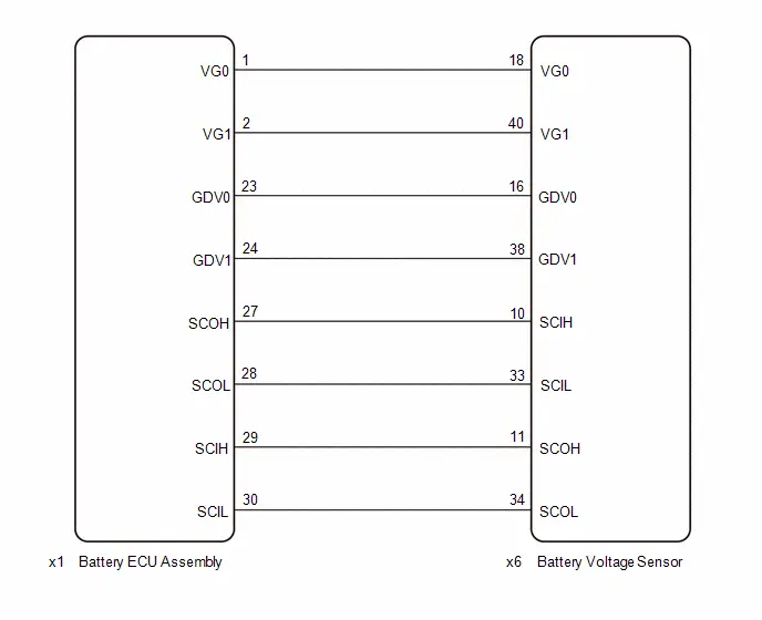
Refer to the wiring diagram for DTC P1A001C.
Click here

CAUTION / NOTICE / HINT
CAUTION:
Refer to the precautions before inspecting high voltage circuit.
Click here

NOTICE:
-
After the ignition switch is turned off, there may be a waiting time before disconnecting the auxiliary negative (-) battery terminal.
Click here

-
When disconnecting and reconnecting the auxiliary battery.
HINT:
When disconnecting and reconnecting the auxiliary battery, there is an automatic learning function that completes learning when the respective system is used.
Click here

PROCEDURE
| 1. | CHECK DTC OUTPUT (HV BATTERY, HYBRID CONTROL) |
Pre-procedure1
(a) None
Procedure1
(b) Check for DTCs.
Powertrain > HV Battery > Trouble Codes Powertrain > Hybrid Control > Trouble Codes| Result | Proceed to |
|---|---|
| "P0E2D00" only is output, or DTCs except the ones in the table below are also output. | A |
| DTCs of hybrid battery system in the table below are output. | B |
| DTCs of hybrid control system in the table below are output. | C |
| System | Relevant DTC | |
|---|---|---|
| Hybrid battery system | P060A47 | Hybrid/EV Battery Energy Control Module Monitoring Processor Watchdog / Safety MCU Failure |
| P060B49 | Hybrid/EV Battery Energy Control Module A/D Processing Internal Electronic Failure | |
| P060687 | Hybrid/EV Battery Energy Control Module Processor to Monitoring Processor Missing Message | |
| P1A001C | Hybrid Battery Stack 2 Cell Voltage Detection Voltage Out of Range | |
| P1A051C | Hybrid Battery Stack 3 Cell Voltage Detection Voltage Out of Range | |
| P1A0A1C | Hybrid Battery Stack 4 Cell Voltage Detection Voltage Out of Range | |
| P1AC413 | Hybrid/EV Battery Stack 1 Current Interrupt Device Circuit Open | |
| P1AC513 | Hybrid/EV Battery Stack 2 Current Interrupt Device Circuit Open | |
| P1AC613 | Hybrid/EV Battery Stack 3 Current Interrupt Device Circuit Open | |
| P1AC713 | Hybrid/EV Battery Stack 4 Current Interrupt Device Circuit Open | |
| P1AC49E | Hybrid/EV Battery Stack 1 Current Interrupt Device Stuck On | |
| P1AC59E | Hybrid/EV Battery Stack 2 Current Interrupt Device Stuck On | |
| P1AC69E | Hybrid/EV Battery Stack 3 Current Interrupt Device Stuck On | |
| P1AC79E | Hybrid/EV Battery Stack 4 Current Interrupt Device Stuck On | |
| P301A1C | Hybrid Battery Stack 1 Cell Voltage Detection Voltage Out of Range | |
| Hybrid control system | P0AA649 | Hybrid/EV Battery Voltage System Isolation Internal Electronic Failure |
| P0A1F94 | Hybrid/EV Battery Energy Control Module Unexpected Operation | |
Post-procedure1
(c) Turn the ignition switch off.
| B |

| GO TO DTC CHART (HYBRID BATTERY SYSTEM) |
| C |

| GO TO DTC CHART (HYBRID CONTROL SYSTEM) |
|

| 2. | CHECK FREEZE FRAME DATA |
Pre-procedure1
(a) None
Procedure1
(b) Read the value of freeze frame data items "Lost Communication with Hybrid/EV Battery Monitoring IC", "Hybrid/EV Battery Monitoring IC 1 Internal Malfunction (Determinable)" through "Hybrid/EV Battery Monitoring IC 3 Internal Malfunction (Determinable)", "Hybrid/EV Battery Monitoring IC Internal Malfunction (Unidentifiable)", "Hybrid/EV Battery Monitoring IC 1 Power Supply Malfunction" through "Hybrid/EV Battery Monitoring IC 3 Power Supply Malfunction" and "Hybrid/EV Battery Monitoring IC 1 Cell Voltage Detection Malfunction" through "Hybrid/EV Battery Monitoring IC 3 Cell Voltage Detection Malfunction" for DTC P0E2D00 and make a note.
Powertrain > HV Battery > Trouble Codes| Result | Proceed to |
|---|---|
| The freeze frame data item "Hybrid/EV Battery Monitoring IC Internal Malfunction (Unidentifiable)" is ON. | A |
| Either freeze frame data item "Hybrid/EV Battery Monitoring IC 1 Internal Malfunction (Determinable)" through "Hybrid/EV Battery Monitoring IC 3 Internal Malfunction (Determinable)" is ON. | B |
| Any of the freeze frame data items "Hybrid/EV Battery Monitoring IC 1 Power Supply Malfunction" through "Hybrid/EV Battery Monitoring IC 3 Power Supply Malfunction" is ON. | C |
| The freeze frame data item "Lost Communication with Hybrid/EV Battery Monitoring IC" is ON. | D |
| Any of the freeze frame data items "Hybrid/EV Battery Monitoring IC 1 Cell Voltage Detection Malfunction" through "Hybrid/EV Battery Monitoring IC 3 Power Supply Malfunction" is ON. | E |
HINT:
- The chart above is listed in inspection order of priority.
- Check items that are ON at the same time by following the listed order.
Post-procedure1
(c) Turn the ignition switch off.
| A |

| REPLACE BATTERY VOLTAGE SENSOR |
| B |

| REPLACE BATTERY VOLTAGE SENSOR |
| D |

| GO TO STEP 4 |
| E |

| GO TO STEP 5 |
|

| 3. | CHECK HARNESS AND CONNECTOR (BATTERY ECU ASSEMBLY - BATTERY VOLTAGE SENSOR) |
CAUTION:
Be sure to wear insulated gloves and protective goggles.
NOTICE:
Make sure to use tester probes with a diameter of approximately 0.5 mm (0.0197 in.) when measuring the voltage of each HV battery cell.
Pre-procedure1
(a) Check that the service plug grip is not installed.
NOTICE:
After removing the service plug grip, do not turn the ignition switch to ON (READY), unless instructed by the repair manual because this may cause a malfunction.
| (b) Disconnect the battery ECU assembly connector. NOTICE: Before disconnecting the connector, check that it is not loose or disconnected. |
|

| (c) Disconnect the x6 battery voltage sensor connector. CAUTION: When disconnecting connector x6 of the battery voltage sensor, first disconnect connectors z17, z18, z19, z20, z21 and z22 from the battery voltage sensor. NOTICE:
|
|

Procedure1
(d) Measure the resistance according to the value(s) in the table below.
Standard Resistance:
 Click Location & Routing(x1,x6) Click Connector(x1) Click Connector(x6)
 | Tester Connection | Condition | Specified Condition |
|---|---|---|
| x1-1 (VG0) - x6-18 (VG0) | Ignition switch off | Below 1 Ω |
| x1-2 (VG1) - x6-40 (VG1) | Ignition switch off | Below 1 Ω |
| x1-23 (GDV0) - x6-16 (GDV0) | Ignition switch off | Below 1 Ω |
| x1-24 (GDV1) - x6-38 (GDV1) | Ignition switch off | Below 1 Ω |
Post-procedure1
| (e) Reconnect the x6 battery voltage sensor connector. CAUTION: When connecting connectors z17, z18, z19, z20, z21 and z22 of the battery voltage sensor, first connect connector x6 to the battery voltage sensor. |
|

(f) Reconnect the battery ECU assembly connector.
| OK |

| REPLACE BATTERY VOLTAGE SENSOR |
| NG |

| REPAIR OR REPLACE HARNESS OR CONNECTOR |
| 4. | CHECK HARNESS AND CONNECTOR (BATTERY ECU ASSEMBLY - BATTERY VOLTAGE SENSOR) |
CAUTION:
Be sure to wear insulated gloves and protective goggles.
NOTICE:
Make sure to use tester probes with a diameter of approximately 0.5 mm (0.0197 in.) when measuring the voltage of each HV battery cell.
Pre-procedure1
(a) Check that the service plug grip is not installed.
NOTICE:
After removing the service plug grip, do not turn the ignition switch to ON (READY), unless instructed by the repair manual because this may cause a malfunction.
| (b) Disconnect the battery ECU assembly connector. NOTICE: Before disconnecting the connector, check that it is not loose or disconnected. |
|
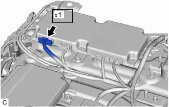
| (c) Disconnect the x6 battery voltage sensor connector. CAUTION: When disconnecting connector x6 of the battery voltage sensor, first disconnect connectors z17, z18, z19, z20, z21 and z22 from the battery voltage sensor. NOTICE:
|
|

Procedure1
(d) Measure the resistance according to the value(s) in the table below.
Standard Resistance:
 Click Location & Routing(x1,x6) Click Connector(x1) Click Connector(x6)
 | Tester Connection | Condition | Specified Condition |
|---|---|---|
| x1-27 (SCOH) - x6-10 (SCIH) | Ignition switch off | Below 1 Ω |
| x1-28 (SCOL) - x6-33 (SCIL) | Ignition switch off | Below 1 Ω |
| x1-29 (SCIH) - x6-11 (SCOH) | Ignition switch off | Below 1 Ω |
| x1-30 (SCIL) - x6-34 (SCOL) | Ignition switch off | Below 1 Ω |
Post-procedure1
| (e) Reconnect the x6 battery voltage sensor connector. CAUTION: When connecting connectors z17, z18, z19, z20, z21 and z22 of the battery voltage sensor, first connect connector x6 to the battery voltage sensor. |
|
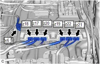
(f) Reconnect the battery ECU assembly connector.
| OK |

| REPLACE BATTERY ECU ASSEMBLY AND BATTERY VOLTAGE SENSOR Battery ECU assembly: Click here
Battery voltage sensor: Click here
|


| NG |

| REPAIR OR REPLACE HARNESS OR CONNECTOR |
| 5. | CHECK CONNECTOR CONNECTION CONDITION (BATTERY VOLTAGE SENSOR CONNECTOR) |
CAUTION:
Be sure to wear insulated gloves and protective goggles.
Pre-procedure1
(a) Check that the service plug grip is not installed.
NOTICE:
After removing the service plug grip, do not turn the ignition switch to ON (READY), unless instructed by the repair manual because this may cause a malfunction.
Procedure1
| (b) Check the connections of the battery voltage sensor connector. Click here
OK: The connector is connected securely and there are no contact problems. Result:
|
| ||||||||||||||||||||||||||||


Post-procedure1
(c) None
| B |

| CONNECT SECURELY |
| C |

| REPLACE NO. 1 HV SUPPLY STACK SUB-ASSEMBLY |
| D |

| REPLACE NO. 1 HV SUPPLY STACK SUB-ASSEMBLY |
| E |

| REPLACE NO. 2 HV SUPPLY STACK SUB-ASSEMBLY |
| F |

| REPLACE NO. 2 HV SUPPLY STACK SUB-ASSEMBLY |
| G |

| REPLACE NO. 3 HV SUPPLY STACK SUB-ASSEMBLY |
| H |

| REPLACE NO. 3 HV SUPPLY STACK SUB-ASSEMBLY |
|

| 6. | CHECK FREEZE FRAME DATA |
Pre-procedure1
(a) None
Procedure1
(b) Read the value of freeze frame data items "Hybrid/EV Battery Cell 1 Voltage" through "Hybrid/EV Battery Cell 72 Voltage" for DTC P0E2D00 and make a note if the value of any is 1.6 V or less.
Powertrain > HV Battery > Trouble Codes| Result | Proceed to |
|---|---|
| The value of any of the freeze frame data items "Hybrid/EV Battery Cell 1 Voltage" through "Hybrid/EV Battery Cell 24 Voltage" is 1.6 V or less. | A |
| The value of any of the freeze frame data items "Hybrid/EV Battery Cell 25 Voltage" through "Hybrid/EV Battery Cell 48 Voltage" is 1.6 V or less. | B |
| The value of any of the freeze frame data items "Hybrid/EV Battery Cell 49 Voltage" through "Hybrid/EV Battery Cell 72 Voltage" is 1.6 V or less. | C |
| Other than above | D |
Post-procedure1
(c) Turn the ignition switch off.
| B |

| GO TO STEP 10 |
| C |

| GO TO STEP 13 |
| D |

| REPLACE BATTERY VOLTAGE SENSOR |
|

| 7. | CHECK NO. 1 HV SUPPLY STACK SUB-ASSEMBLY (HYBRID BATTERY CELL 1 TO 24 VOLTAGE) |
CAUTION:
- Be sure to wear insulated gloves and protective goggles.
- Disconnect only the connector corresponding to the HV battery cell to be checked. Do not disconnect the other connectors.
NOTICE:
Make sure to use tester probes with a diameter of approximately 0.5 mm (0.0197 in.) when measuring the voltage of each HV battery cell.
Pre-procedure1
(a) Check that the service plug grip is not installed.
NOTICE:
After removing the service plug grip, do not turn the ignition switch to ON (READY), unless instructed by the repair manual because this may cause a malfunction.
| (b) Disconnect the battery voltage sensor connector. NOTICE: Before disconnecting the connector, check that it is not loose or disconnected. |
|

Procedure1
(c) Measure the voltage according to the value(s) in the table below.
HINT:
Measure the voltage of the HV battery cells whose value in the freeze frame data was 1.6 V or less only.
| Hybrid Battery Cell | Tester Connection (Tester Probe Polarity) | Condition |
|---|---|---|
| 1 | z18-6 (GA0) (-) - z18-5 (VA1) ( ) | Always |
| 2 | z18-5 (VA1) (-) - z18-4 (VA2) ( ) | Always |
| 3 | z18-4 (VA2) (-) - z18-1 (VA3) ( ) | Always |
| 4 | z18-1 (VA3) (-) - z18-3 (VA4) ( ) | Always |
| 5 | z18-3 (VA4) (-) - z17-27 (VA5) ( ) | Always |
| 6 | z17-27 (VA5) (-) - z17-17 (VA6) ( ) | Always |
| 7 | z17-17 (VA6) (-) - z17-16 (VA7) ( ) | Always |
| 8 | z17-16 (VA7) (-) - z17-4 (VA8) ( ) | Always |
| 9 | z17-4 (VA8) (-) - z17-3 (VA9) ( ) | Always |
| 10 | z17-3 (VA9) (-) - z17-15 (VA10) ( ) | Always |
| 11 | z17-15 (VA10) (-) - z17-14 (VA11) ( ) | Always |
| 12 | z17-14 (VA11) (-) - z17-13 (VA12) ( ) | Always |
| 13 | z17-12 (GA1) (-) - z17-23 (VA13) ( ) | Always |
| 14 | z17-23 (VA13) (-) - z17-11 (VA14) ( ) | Always |
| 15 | z17-11 (VA14) (-) - z17-10 (VA15) ( ) | Always |
| 16 | z17-10 (VA15) (-) - z17-9 (VA16) ( ) | Always |
| 17 | z17-9 (VA16) (-) - z17-8 (VA17) ( ) | Always |
| 18 | z17-8 (VA17) (-) - z17-20 (VA18) ( ) | Always |
| 19 | z17-20 (VA18) (-) - z17-7 (VA19) ( ) | Always |
| 20 | z17-7 (VA19) (-) - z17-2 (VA20) ( ) | Always |
| 21 | z17-2 (VA20) (-) - z17-1 (VA21) ( ) | Always |
| 22 | z17-1 (VA21) (-) - z17-6 (VA22) ( ) | Always |
| 23 | z17-6 (VA22) (-) - z17-5 (VA23) ( ) | Always |
| 24 | z17-5 (VA23) (-) - z17-18 (VA24) ( ) | Always |
CAUTION:
Make sure not to cross the electrodes of an electrical tester measurement terminals.
NOTICE:
Make sure to check the polarity of each terminal (positive ( ) or negative (-)) before connecting a tester.
| Result | Proceed to |
|---|---|
| The voltage between the terminals is 1.6 V or less. | A |
| Other than above | B |
Post-procedure1
(d) Reconnect the battery voltage sensor connector.
| B |

| REPLACE BATTERY VOLTAGE SENSOR |
|

| 8. | CHECK BATTERY VOLTAGE SENSOR (VA1 - VA24) |
NOTICE:
Make sure to use tester probes with a diameter of approximately 0.5 mm (0.0197 in.) when measuring the resistance.
Pre-procedure1
(a) Remove the battery voltage sensor.
HINT:
Click here

Procedure1
(b) Measure the resistance according to the value(s) in the table below.
HINT:
Only inspect the terminals of the battery voltage sensor which correspond to the HV battery cells which measured 1.6 V or less in the previous step.
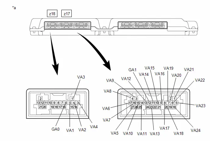
| *a | Component without harness connected (Battery Voltage Sensor) | - | - |
Standard Resistance:
| Hybrid Battery Cell | Tester Connection (Tester Probe Polarity) | Condition | Specified Condition |
|---|---|---|---|
| 1 | z18-6 (GA0) (-) - z18-5 (VA1) ( ) | Always | 50 kΩ or more |
| 2 | z18-5 (VA1) (-) - z18-4 (VA2) ( ) | Always | 50 kΩ or more |
| 3 | z18-4 (VA2) (-) - z18-1 (VA3) ( ) | Always | 50 kΩ or more |
| 4 | z18-1 (VA3) (-) - z18-3 (VA4) ( ) | Always | 50 kΩ or more |
| 5 | z18-3 (VA4) (-) - z17-27 (VA5) ( ) | Always | 50 kΩ or more |
| 6 | z17-27 (VA5) (-) - z17-17 (VA6) ( ) | Always | 50 kΩ or more |
| 7 | z17-17 (VA6) (-) - z17-16 (VA7) ( ) | Always | 50 kΩ or more |
| 8 | z17-16 (VA7) (-) - z17-4 (VA8) ( ) | Always | 50 kΩ or more |
| 9 | z17-4 (VA8) (-) - z17-3 (VA9) ( ) | Always | 50 kΩ or more |
| 10 | z17-3 (VA9) (-) - z17-15 (VA10) ( ) | Always | 50 kΩ or more |
| 11 | z17-15 (VA10) (-) - z17-14 (VA11) ( ) | Always | 50 kΩ or more |
| 12 | z17-14 (VA11) (-) - z17-13 (VA12) ( ) | Always | 50 kΩ or more |
| 13 | z17-12 (GA1) (-) - z17-23 (VA13) ( ) | Always | 50 kΩ or more |
| 14 | z17-23 (VA13) (-) - z17-11 (VA14) ( ) | Always | 50 kΩ or more |
| 15 | z17-11 (VA14) (-) - z17-10 (VA15) ( ) | Always | 50 kΩ or more |
| 16 | z17-10 (VA15) (-) - z17-9 (VA16) ( ) | Always | 50 kΩ or more |
| 17 | z17-9 (VA16) (-) - z17-8 (VA17) ( ) | Always | 50 kΩ or more |
| 18 | z17-8 (VA17) (-) - z17-20 (VA18) ( ) | Always | 50 kΩ or more |
| 19 | z17-20 (VA18) (-) - z17-7 (VA19) ( ) | Always | 50 kΩ or more |
| 20 | z17-7 (VA19) (-) - z17-2 (VA20) ( ) | Always | 50 kΩ or more |
| 21 | z17-2 (VA20) (-) - z17-1 (VA21) ( ) | Always | 50 kΩ or more |
| 22 | z17-1 (VA21) (-) - z17-6 (VA22) ( ) | Always | 50 kΩ or more |
| 23 | z17-6 (VA22) (-) - z17-5 (VA23) ( ) | Always | 50 kΩ or more |
| 24 | z17-5 (VA23) (-) - z17-18 (VA24) ( ) | Always | 50 kΩ or more |
NOTICE:
- Make sure to check the polarity of each terminal (positive ( ) or negative (-)) before connecting a tester.
- Read the resistance after the value has stabilized.
- In order to avoid damaging the terminals of the battery voltage sensor, make sure to use tester probes with a diameter of approximately 0.5 mm (0.0197 in.) when measuring the resistance of the battery voltage sensor.
| Result | Proceed to |
|---|---|
| The resistance between the terminals is 50 kΩ or more. | A |
| Other than above | B |
Post-procedure1
(c) Install the battery voltage sensor.
| A |

| REPLACE NO. 1 HV SUPPLY STACK SUB-ASSEMBLY |
|

| 9. | REPLACE NO. 1 HV SUPPLY STACK SUB-ASSEMBLY |
HINT:
Click here

| NEXT |

| REPLACE BATTERY VOLTAGE SENSOR |
| 10. | CHECK NO. 2 HV SUPPLY STACK SUB-ASSEMBLY (HYBRID BATTERY CELL 25 TO 48 VOLTAGE) |
CAUTION:
- Be sure to wear insulated gloves and protective goggles.
- Disconnect only the connector corresponding to the HV battery cell to be checked. Do not disconnect the other connectors.
NOTICE:
Make sure to use tester probes with a diameter of approximately 0.5 mm (0.0197 in.) when measuring the voltage of each HV battery cell.
Pre-procedure1
(a) Check that the service plug grip is not installed.
NOTICE:
After removing the service plug grip, do not turn the ignition switch to ON (READY), unless instructed by the repair manual because this may cause a malfunction.
| (b) Disconnect the battery voltage sensor connectors. NOTICE: Before disconnecting the connector, check that it is not loose or disconnected. |
|

Procedure1
(c) Measure the voltage according to the value(s) in the table below.
HINT:
Measure the voltage of the HV battery cells whose value in the freeze frame data was 1.6 V or less only.
| Hybrid Battery Cell | Tester Connection (Tester Probe Polarity) | Condition |
|---|---|---|
| 25 | z20-12 (GA2) (-) - z20-11 (VA25) ( ) | Always |
| 26 | z20-11 (VA25) (-) - z20-10 (VA26) ( ) | Always |
| 27 | z20-10 (VA26) (-) - z20-9 (VA27) ( ) | Always |
| 28 | z20-9 (VA27) (-) - z20-8 (VA28) ( ) | Always |
| 29 | z20-8 (VA28) (-) - z20-20 (VA29) ( ) | Always |
| 30 | z20-20 (VA29) (-) - z20-7 (VA30) ( ) | Always |
| 31 | z20-7 (VA30) (-) - z20-2 (VA31) ( ) | Always |
| 32 | z20-2 (VA31) (-) - z20-1 (VA32) ( ) | Always |
| 33 | z20-1 (VA32) (-) - z20-6 (VA33) ( ) | Always |
| 34 | z20-6 (VA33) (-) - z20-5 (VA34) ( ) | Always |
| 35 | z20-5 (VA34) (-) - z20-18 (VA35) ( ) | Always |
| 36 | z20-18 (VA35) (-) - z19-21 (VA36) ( ) | Always |
| 37 | z19-13 (GA3) (-) - z19-2 (VA37) ( ) | Always |
| 38 | z19-2 (VA37) (-) - z19-12 (VA38) ( ) | Always |
| 39 | z19-12 (VA38) (-) - z19-11 (VA39) ( ) | Always |
| 40 | z19-11 (VA39) (-) - z19-10 (VA40) ( ) | Always |
| 41 | z19-10 (VA40) (-) - z19-9 (VA41) ( ) | Always |
| 42 | z19-9 (VA41) (-) - z19-8 (VA42) ( ) | Always |
| 43 | z19-8 (VA42) (-) - z19-7 (VA43) ( ) | Always |
| 44 | z19-7 (VA43) (-) - z19-6 (VA44) ( ) | Always |
| 45 | z19-6 (VA44) (-) - z19-5 (VA45) ( ) | Always |
| 46 | z19-5 (VA45) (-) - z19-4 (VA46) ( ) | Always |
| 47 | z19-4 (VA46) (-) - z19-1 (VA47) ( ) | Always |
| 48 | z19-1 (VA47) (-) - z19-3 (VA48) ( ) | Always |
CAUTION:
Make sure not to cross the electrodes of an electrical tester measurement terminals.
NOTICE:
Make sure to check the polarity of each terminal (positive ( ) or negative (-)) before connecting a tester.
| Result | Proceed to |
|---|---|
| The voltage between the terminals is 1.6 V or less. | A |
| Other than above | B |
Post-procedure1
(d) Reconnect the battery voltage sensor connectors.
| B |

| REPLACE BATTERY VOLTAGE SENSOR |
|

| 11. | CHECK BATTERY VOLTAGE SENSOR (VA25 - VA48) |
NOTICE:
Make sure to use tester probes with a diameter of approximately 0.5 mm (0.0197 in.) when measuring the resistance.
Pre-procedure1
(a) Remove the battery voltage sensor.
HINT:
Click here

Procedure1
(b) Measure the resistance according to the value(s) in the table below.
HINT:
Only inspect the terminals of the battery voltage sensor which correspond to the HV battery cells which measured 1.6 V or less in the previous step.

| *a | Component without harness connected (Battery Voltage Sensor) | - | - |
Standard Resistance:
| Hybrid Battery Cell | Tester Connection (Tester Probe Polarity) | Condition | Specified Condition |
|---|---|---|---|
| 25 | z20-12 (GA2) (-) - z20-11 (VA25) ( ) | Always | 50 kΩ or more |
| 26 | z20-11 (VA25) (-) - z20-10 (VA26) ( ) | Always | 50 kΩ or more |
| 27 | z20-10 (VA26) (-) - z20-9 (VA27) ( ) | Always | 50 kΩ or more |
| 28 | z20-9 (VA27) (-) - z20-8 (VA28) ( ) | Always | 50 kΩ or more |
| 29 | z20-8 (VA28) (-) - z20-20 (VA29) ( ) | Always | 50 kΩ or more |
| 30 | z20-20 (VA29) (-) - z20-7 (VA30) ( ) | Always | 50 kΩ or more |
| 31 | z20-7 (VA30) (-) - z20-2 (VA31) ( ) | Always | 50 kΩ or more |
| 32 | z20-2 (VA31) (-) - z20-1 (VA32) ( ) | Always | 50 kΩ or more |
| 33 | z20-1 (VA32) (-) - z20-6 (VA33) ( ) | Always | 50 kΩ or more |
| 34 | z20-6 (VA33) (-) - z20-5 (VA34) ( ) | Always | 50 kΩ or more |
| 35 | z20-5 (VA34) (-) - z20-18 (VA35) ( ) | Always | 50 kΩ or more |
| 36 | z20-18 (VA35) (-) - z19-21 (VA36) ( ) | Always | 50 kΩ or more |
| 37 | z19-13 (GA3) (-) - z19-2 (VA37) ( ) | Always | 50 kΩ or more |
| 38 | z19-2 (VA37) (-) - z19-12 (VA38) ( ) | Always | 50 kΩ or more |
| 39 | z19-12 (VA38) (-) - z19-11 (VA39) ( ) | Always | 50 kΩ or more |
| 40 | z19-11 (VA39) (-) - z19-10 (VA40) ( ) | Always | 50 kΩ or more |
| 41 | z19-10 (VA40) (-) - z19-9 (VA41) ( ) | Always | 50 kΩ or more |
| 42 | z19-9 (VA41) (-) - z19-8 (VA42) ( ) | Always | 50 kΩ or more |
| 43 | z19-8 (VA42) (-) - z19-7 (VA43) ( ) | Always | 50 kΩ or more |
| 44 | z19-7 (VA43) (-) - z19-6 (VA44) ( ) | Always | 50 kΩ or more |
| 45 | z19-6 (VA44) (-) - z19-5 (VA45) ( ) | Always | 50 kΩ or more |
| 46 | z19-5 (VA45) (-) - z19-4 (VA46) ( ) | Always | 50 kΩ or more |
| 47 | z19-4 (VA46) (-) - z19-1 (VA47) ( ) | Always | 50 kΩ or more |
| 48 | z19-1 (VA47) (-) - z19-3 (VA48) ( ) | Always | 50 kΩ or more |
NOTICE:
- Make sure to check the polarity of each terminal (positive ( ) or negative (-)) before connecting a tester.
- Read the resistance after the value has stabilized.
- In order to avoid damaging the terminals of the battery voltage sensor, make sure to use tester probes with a diameter of approximately 0.5 mm (0.0197 in.) when measuring the resistance of the battery voltage sensor.
| Result | Proceed to |
|---|---|
| The resistance between the terminals is 50 kΩ or more. | A |
| Other than above | B |
Post-procedure1
(c) Install the battery voltage sensor.
| A |

| REPLACE NO. 2 HV SUPPLY STACK SUB-ASSEMBLY |
|

| 12. | REPLACE NO. 2 HV SUPPLY STACK SUB-ASSEMBLY |
HINT:
Click here

| NEXT |

| REPLACE BATTERY VOLTAGE SENSOR |
| 13. | CHECK NO. 3 HV SUPPLY STACK SUB-ASSEMBLY (HYBRID BATTERY CELL 49 TO 72 VOLTAGE) |
CAUTION:
- Be sure to wear insulated gloves and protective goggles.
- Disconnect only the connector corresponding to the HV battery cell to be checked. Do not disconnect the other connectors.
NOTICE:
Make sure to use tester probes with a diameter of approximately 0.5 mm (0.0197 in.) when measuring the voltage of each HV battery cell.
Pre-procedure1
(a) Check that the service plug grip is not installed.
NOTICE:
After removing the service plug grip, do not turn the ignition switch to ON (READY), unless instructed by the repair manual because this may cause a malfunction.
| (b) Disconnect the battery voltage sensor connectors. NOTICE: Before disconnecting the connector, check that it is not loose or disconnected. |
|

Procedure1
(c) Measure the voltage according to the value(s) in the table below.
HINT:
Measure the voltage of the HV battery cells whose value in the freeze frame data was 1.6 V or less only.
| Hybrid Battery Cell | Tester Connection (Tester Probe Polarity) | Condition |
|---|---|---|
| 49 | z22-11 (GA4) (-) - z22-10 (VA49) ( ) | Always |
| 50 | z22-10 (VA49) (-) - z22-9 (VA50) ( ) | Always |
| 51 | z22-9 (VA50) (-) - z22-3 (VA51) ( ) | Always |
| 52 | z22-3 (VA51) (-) - z22-8 (VA52) ( ) | Always |
| 53 | z22-8 (VA52) (-) - z22-2 (VA53) ( ) | Always |
| 54 | z22-2 (VA53) (-) - z22-7 (VA54) ( ) | Always |
| 55 | z22-7 (VA54) (-) - z22-1 (VA55) ( ) | Always |
| 56 | z22-1 (VA55) (-) - z22-6 (VA56) ( ) | Always |
| 57 | z22-6 (VA56) (-) - z21-17 (VA57) ( ) | Always |
| 58 | z21-17 (VA57) (-) - z21-16 (VA58) ( ) | Always |
| 59 | z21-16 (VA58) (-) - z21-4 (VA59) ( ) | Always |
| 60 | z21-4 (VA59) (-) - z21-3 (VA60) ( ) | Always |
| 61 | z21-15 (GA5) (-) - z21-14 (VA61) ( ) | Always |
| 62 | z21-14 (VA61) (-) - z21-13 (VA62) ( ) | Always |
| 63 | z21-13 (VA62) (-) - z21-12 (VA63) ( ) | Always |
| 64 | z21-12 (VA63) (-) - z21-11 (VA64) ( ) | Always |
| 65 | z21-11 (VA64) (-) - z21-10 (VA65) ( ) | Always |
| 66 | z21-10 (VA65) (-) - z21-9 (VA66) ( ) | Always |
| 67 | z21-9 (VA66) (-) - z21-8 (VA67) ( ) | Always |
| 68 | z21-8 (VA67) (-) - z21-7 (VA68) ( ) | Always |
| 69 | z21-7 (VA68) (-) - z21-2 (VA69) ( ) | Always |
| 70 | z21-2 (VA69) (-) - z21-1 (VA70) ( ) | Always |
| 71 | z21-1 (VA70) (-) - z21-6 (VA71) ( ) | Always |
| 72 | z21-6 (VA71) (-) - z21-5 (VA72) ( ) | Always |
CAUTION:
Make sure not to cross the electrodes of an electrical tester measurement terminals.
NOTICE:
Make sure to check the polarity of each terminal (positive ( ) or negative (-)) before connecting a tester.
| Result | Proceed to |
|---|---|
| The voltage between the terminals is 1.6 V or less. | A |
| Other than above | B |
Post-procedure1
(d) Reconnect the battery voltage sensor connectors.
| B |

| REPLACE BATTERY VOLTAGE SENSOR |
|

| 14. | CHECK BATTERY VOLTAGE SENSOR (VA49 - VA72) |
NOTICE:
Make sure to use tester probes with a diameter of approximately 0.5 mm (0.0197 in.) when measuring the resistance.
Pre-procedure1
(a) Remove the battery voltage sensor.
HINT:
Click here

Procedure1
(b) Measure the resistance according to the value(s) in the table below.
HINT:
Only inspect the terminals of the battery voltage sensor which correspond to the HV battery cells which measured 1.6 V or less in the previous step.

| *a | Component without harness connected (Battery Voltage Sensor) | - | - |
Standard Resistance:
| Hybrid Battery Cell | Tester Connection (Tester Probe Polarity) | Condition | Specified Condition |
|---|---|---|---|
| 49 | z22-11 (GA4) (-) - z22-10 (VA49) ( ) | Always | 50 kΩ or more |
| 50 | z22-10 (VA49) (-) - z22-9 (VA50) ( ) | Always | 50 kΩ or more |
| 51 | z22-9 (VA50) (-) - z22-3 (VA51) ( ) | Always | 50 kΩ or more |
| 52 | z22-3 (VA51) (-) - z22-8 (VA52) ( ) | Always | 50 kΩ or more |
| 53 | z22-8 (VA52) (-) - z22-2 (VA53) ( ) | Always | 50 kΩ or more |
| 54 | z22-2 (VA53) (-) - z22-7 (VA54) ( ) | Always | 50 kΩ or more |
| 55 | z22-7 (VA54) (-) - z22-1 (VA55) ( ) | Always | 50 kΩ or more |
| 56 | z22-1 (VA55) (-) - z22-6 (VA56) ( ) | Always | 50 kΩ or more |
| 57 | z22-6 (VA56) (-) - z21-17 (VA57) ( ) | Always | 50 kΩ or more |
| 58 | z21-17 (VA57) (-) - z21-16 (VA58) ( ) | Always | 50 kΩ or more |
| 59 | z21-16 (VA58) (-) - z21-4 (VA59) ( ) | Always | 50 kΩ or more |
| 60 | z21-4 (VA59) (-) - z21-3 (VA60) ( ) | Always | 50 kΩ or more |
| 61 | z21-15 (GA5) (-) - z21-14 (VA61) ( ) | Always | 50 kΩ or more |
| 62 | z21-14 (VA61) (-) - z21-13 (VA62) ( ) | Always | 50 kΩ or more |
| 63 | z21-13 (VA62) (-) - z21-12 (VA63) ( ) | Always | 50 kΩ or more |
| 64 | z21-12 (VA63) (-) - z21-11 (VA64) ( ) | Always | 50 kΩ or more |
| 65 | z21-11 (VA64) (-) - z21-10 (VA65) ( ) | Always | 50 kΩ or more |
| 66 | z21-10 (VA65) (-) - z21-9 (VA66) ( ) | Always | 50 kΩ or more |
| 67 | z21-9 (VA66) (-) - z21-8 (VA67) ( ) | Always | 50 kΩ or more |
| 68 | z21-8 (VA67) (-) - z21-7 (VA68) ( ) | Always | 50 kΩ or more |
| 69 | z21-7 (VA68) (-) - z21-2 (VA69) ( ) | Always | 50 kΩ or more |
| 70 | z21-2 (VA69) (-) - z21-1 (VA70) ( ) | Always | 50 kΩ or more |
| 71 | z21-1 (VA70) (-) - z21-6 (VA71) ( ) | Always | 50 kΩ or more |
| 72 | z21-6 (VA71) (-) - z21-5 (VA72) ( ) | Always | 50 kΩ or more |
NOTICE:
- Make sure to check the polarity of each terminal (positive ( ) or negative (-)) before connecting a tester.
- Read the resistance after the value has stabilized.
- In order to avoid damaging the terminals of the battery voltage sensor, make sure to use tester probes with a diameter of approximately 0.5 mm (0.0197 in.) when measuring the resistance of the battery voltage sensor.
| Result | Proceed to |
|---|---|
| The resistance between the terminals is 50 kΩ or more. | A |
| Other than above | B |
Post-procedure1
(c) Install the battery voltage sensor.
| A |

| REPLACE NO. 3 HV SUPPLY STACK SUB-ASSEMBLY |
|

| 15. | REPLACE NO. 3 HV SUPPLY STACK SUB-ASSEMBLY |
HINT:
Click here

| NEXT |

| REPLACE BATTERY VOLTAGE SENSOR |
Hybrid/EV Battery Charging System Precharge Contactor Control Circuit Short to Ground (P0E6D11)
DESCRIPTION
Refer to the description for DTC P0D0A11.
Click here

| DTC No. | Detection Item | DTC Detection Condition | Trouble Area | MIL | Warning Indicate | DTC Output from | Priority | Note |
|---|---|---|---|---|---|---|---|---|
| P0E6D11 | Hybrid/EV Battery Charging System Precharge Contactor Control Circuit Short to Ground | Short to ground in the CHRP circuit: Primary circuit of CHRP is malfunctioning. (1 trip detection logic) |
| Comes on | Master Warning: Comes on | HV Battery | A | SAE Code: P0E6F |
MONITOR DESCRIPTION
If the battery ECU assembly detects a malfunction of its HV battery charging system precharge contactor control circuit (CHRP), the battery ECU assembly illuminates the MIL and stores a DTC.
MONITOR STRATEGY
| Related DTCs | P0E6F (INF P0E6D11): Battery Charging System Precharge Contactor Control Circuit |
| Required sensors/components | Charge relay |
| Frequency of operation | Continuous |
| Duration | TMC's intellectual property |
| MIL operation | Immediately |
| Sequence of operation | None |
TYPICAL ENABLING CONDITIONS
| The monitor will run whenever the following DTCs are not stored | TMC's intellectual property |
| Other conditions belong to TMC's intellectual property | - |
TYPICAL MALFUNCTION THRESHOLDS
| TMC's intellectual property | - |
COMPONENT OPERATING RANGE
| Battery ECU assembly | DTC P0E6F (INF P0E6D11) is not detected |
CONFIRMATION DRIVING PATTERN
HINT:
-
After repair has been completed, clear the DTC and then check that the Toyota Prius vehicle has returned to normal by performing the following All Readiness check procedure.
Click here

-
When clearing the permanent DTCs, refer to the "CLEAR PERMANENT DTC" procedure.
Click here

- Clear the DTCs (even if no DTCs are stored, perform the clear DTC procedure).
- Enter the following menus: Powertrain / Hybrid Control / Data List.[*1]
- Check that "Hybrid/EV Battery SOC" shows 70% or less.[*2]
- Turn the ignition switch off and wait for 2 minutes or more.[*3]
-
Connect the electric Toyota Prius vehicle charger cable assembly, and plug-in charge the vehicle for at least 5 seconds.[*4]
HINT:
[*1] to [*4]: Normal judgment procedure.
The normal judgment procedure is used to complete DTC judgment and also used when clearing permanent DTCs.
- Enter the following menus: Powertrain / HV Battery / Utility / All Readiness.
-
Check the DTC judgment result.
HINT:
- If the judgment result shows NORMAL, the system is normal.
- If the judgment result shows ABNORMAL, the system has a malfunction.
- If the judgment result shows INCOMPLETE or N/A, perform the normal judgment procedure again.
WIRING DIAGRAM
Refer to the wiring diagram for DTC P0D0A11.
Click here

CAUTION / NOTICE / HINT
CAUTION:
Refer to the precautions before inspecting high voltage circuit.
Click here

NOTICE:
-
After the ignition switch is turned off, there may be a waiting time before disconnecting the auxiliary negative (-) battery terminal.
Click here

-
When disconnecting and reconnecting the auxiliary battery.
HINT:
When disconnecting and reconnecting the auxiliary battery, there is an automatic learning function that completes learning when the respective system is used.
Click here

PROCEDURE
| 1. | CHECK CONNECTOR CONNECTION CONDITION (BATTERY ECU ASSEMBLY) |
Click here

| NG |

| CONNECT SECURELY |
|

| 2. | CHECK HARNESS AND CONNECTOR (BATTERY ECU ASSEMBLY - BODY GROUND) |
CAUTION:
Be sure to wear insulated gloves and protective goggles.
Pre-procedure1
(a) Check that the service plug grip is not installed.
NOTICE:
After removing the service plug grip, do not turn the ignition switch to ON (READY), unless instructed by the repair manual because this may cause a malfunction.
| (b) Disconnect the battery ECU assembly connector. NOTICE: Before disconnecting the connector, check that it is not loose or disconnected. |
|

Procedure1
(c) Measure the resistance according to the value(s) in the tables below.
Standard Resistance:
 Click Location & Routing(x4) Click Connector(x4)
 | Tester Connection | Condition | Specified Condition | Result |
|---|---|---|---|
| x4-7 (CHRP) - Body ground | Ignition switch off | 140 to 290 Ω | Ω |
Post-procedure1
(d) Reconnect the battery ECU assembly connector.
| OK |

| REPLACE BATTERY ECU ASSEMBLY |
|

| 3. | CHECK CONNECTOR CONNECTION CONDITION (NO. 1 TRACTION BATTERY DEVICE BOX ASSEMBLY) |
Click here

| NG |

| CONNECT SECURELY |
|

| 4. | CHECK HARNESS AND CONNECTOR (BATTERY ECU ASSEMBLY - NO. 1 TRACTION BATTERY DEVICE BOX ASSEMBLY) |
CAUTION:
Be sure to wear insulated gloves and protective goggles.
Pre-procedure1
(a) Check that the service plug grip is not installed.
NOTICE:
After removing the service plug grip, do not turn the ignition switch to ON (READY), unless instructed by the repair manual because this may cause a malfunction.
| (b) Disconnect the battery ECU assembly connector. NOTICE: Before disconnecting the connector, check that it is not loose or disconnected. |
|

| (c) Disconnect the No. 1 traction battery device box assembly connector. NOTICE: Before disconnecting the connector, check that it is not loose or disconnected. |
|

Procedure1
(d) Measure the resistance according to the value(s) in the tables below.
Standard Resistance:
 Click Location & Routing(x13,x4) Click Connector(x13) Click Connector(x4)
 | Tester Connection | Condition | Specified Condition | Result |
|---|---|---|---|
| x13-2 (CHRP) and x4-7 (CHRP) - Body ground and other terminals | Ignition switch off | 10 kΩ or higher | kΩ |
Post-procedure1
(e) Reconnect the No. 1 traction battery device box assembly connector.
(f) Reconnect the battery ECU assembly connector.
| OK |

| REPLACE NO. 1 TRACTION BATTERY DEVICE BOX ASSEMBLY |
| NG |

| REPAIR OR REPLACE HARNESS OR CONNECTOR |
Hybrid/EV Battery Charging System Precharge Contactor Control Circuit Short to Auxiliary Battery or Open (P0E6D15)
DESCRIPTION
Refer to the description for DTC P0D0A11.
Click here

| DTC No. | Detection Item | DTC Detection Condition | Trouble Area | MIL | Warning Indicate | DTC Output from | Priority | Note |
|---|---|---|---|---|---|---|---|---|
| P0E6D15 | Hybrid/EV Battery Charging System Precharge Contactor Control Circuit Short to Auxiliary Battery or Open | Open or short to B in CHRP circuit: Primary circuit of CHRP is malfunctioning. (1 trip detection logic) |
| Comes on | Master Warning: Comes on | HV Battery | A | SAE Code: P0E70 |
MONITOR DESCRIPTION
If the battery ECU assembly detects a malfunction of its HV battery charging system precharge contactor control circuit (CHRP), the battery ECU assembly illuminates the MIL and stores a DTC.
MONITOR STRATEGY
| Related DTCs | P0E70 (INF P0E6D15): Battery Charging System Precharge Contactor Control Circuit |
| Required sensors/components | Charge relay |
| Frequency of operation | Continuous |
| Duration | TMC's intellectual property |
| MIL operation | Immediately |
| Sequence of operation | None |
TYPICAL ENABLING CONDITIONS
| The monitor will run whenever the following DTCs are not stored | TMC's intellectual property |
| Other conditions belong to TMC's intellectual property | - |
TYPICAL MALFUNCTION THRESHOLDS
| TMC's intellectual property | - |
COMPONENT OPERATING RANGE
| Battery ECU assembly | DTC P0E70 (INF P0E6D15) is not detected |
CONFIRMATION DRIVING PATTERN
HINT:
-
After repair has been completed, clear the DTC and then check that the Toyota Prius vehicle has returned to normal by performing the following All Readiness check procedure.
Click here

-
When clearing the permanent DTCs, refer to the "CLEAR PERMANENT DTC" procedure.
Click here

- Clear the DTCs (even if no DTCs are stored, perform the clear DTC procedure).
- Turn the ignition switch off and wait for 2 minutes or more.
-
Turn the ignition switch to ON and wait for 5 seconds or more.[*1]
HINT:
[*1]: Normal judgment procedure.
The normal judgment procedure is used to complete DTC judgment and also used when clearing permanent DTCs.
- Enter the following menus: Powertrain / HV Battery / Utility / All Readiness.
-
Check the DTC judgment result.
HINT:
- If the judgment result shows NORMAL, the system is normal.
- If the judgment result shows ABNORMAL, the system has a malfunction.
- If the judgment result shows INCOMPLETE or N/A, perform the normal judgment procedure again.
WIRING DIAGRAM
Refer to the wiring diagram for DTC P0D0A11.
Click here

CAUTION / NOTICE / HINT
CAUTION:
Refer to the precautions before inspecting high voltage circuit.
Click here

NOTICE:
-
After the ignition switch is turned off, there may be a waiting time before disconnecting the auxiliary negative (-) battery terminal.
Click here

-
When disconnecting and reconnecting the auxiliary battery.
HINT:
When disconnecting and reconnecting the auxiliary battery, there is an automatic learning function that completes learning when the respective system is used.
Click here

PROCEDURE
| 1. | READ VALUE USING GTS (AC CHARGING PRECHARGE RELAY STATUS) |
Pre-procedure1
(a) None
Procedure1
(b) Read the Data List.
Powertrain > HV Battery > Data List| Tester Display |
|---|
| AC Charging Precharge Relay Status |
Standard:
| Tester Display | Condition | Specified Condition |
|---|---|---|
| AC Charging Precharge Relay Status | Ignition switch ON | OFF |
| Result | Proceed to |
|---|---|
| The value of AC Charging Precharge Relay Status is OFF | A |
| The value of AC Charging Precharge Relay Status is ON | B |
Post-procedure1
(c) Turn the ignition switch off.
| B |

| GO TO STEP 4 |
|

| 2. | CHECK CONNECTOR CONNECTION CONDITION (BATTERY ECU ASSEMBLY) |
Click here

| NG |

| CONNECT SECURELY |
|

| 3. | CHECK CONNECTOR CONNECTION CONDITION (NO. 1 TRACTION BATTERY DEVICE BOX ASSEMBLY) |
Click here

| OK |

| CHECK FOR INTERMITTENT PROBLEMS |
| NG |

| CONNECT SECURELY |
| 4. | CHECK CONNECTOR CONNECTION CONDITION (BATTERY ECU ASSEMBLY) |
Click here

| NG |

| CONNECT SECURELY |
|

| 5. | CHECK HARNESS AND CONNECTOR (CHRP VOLTAGE) |
CAUTION:
Be sure to wear insulated gloves and protective goggles.
Pre-procedure1
(a) Check that the service plug grip is not installed.
NOTICE:
After removing the service plug grip, do not turn the ignition switch to ON (READY), unless instructed by the repair manual because this may cause a malfunction.
(b) Connect the SST.
HINT:
Click here

| (c) Disconnect the battery ECU assembly connector. NOTICE: Before disconnecting the connector, check that it is not loose or disconnected. |
|

(d) Connect the cable to the negative (-) auxiliary battery terminal.
(e) Turn the ignition switch to ON.
Procedure1
(f) Measure the voltage according to the value(s) in the table below.
Standard Voltage:
 Click Location & Routing(x4) Click Connector(x4)
 | Tester Connection | Condition | Specified Condition | Result |
|---|---|---|---|
| x4-7 (CHRP) - Body ground | Ignition switch ON | Below 1 V | V |
NOTICE:
- Turning the ignition switch to ON with the service plug grip removed causes other DTCs to be stored. Clear the DTCs after performing this inspection.
- If the ignition switch is turned to ON with the connectors disconnected, other DTCs will be stored. Be sure to clear the DTCs after the inspection.
Post-procedure1
(g) Turn the ignition switch off.
(h) Disconnect the cable from the negative (-) auxiliary battery terminal.
(i) Reconnect the battery ECU assembly connector.
(j) Disconnect the SST.
| OK |

| REPLACE BATTERY ECU ASSEMBLY |
|

| 6. | CHECK HARNESS AND CONNECTOR (BATTERY ECU ASSEMBLY - BODY GROUND) |
Click here

| NG |

| GO TO STEP 9 |
|

| 7. | CHECK CONNECTOR CONNECTION CONDITION (NO. 1 TRACTION BATTERY DEVICE BOX ASSEMBLY) |
Click here

| NG |

| CONNECT SECURELY |
|

| 8. | CHECK HARNESS AND CONNECTOR (SHORT TO POWER SUPPLY WIRES) |
CAUTION:
Be sure to wear insulated gloves and protective goggles.
Pre-procedure1
(a) Check that the service plug grip is not installed.
NOTICE:
After removing the service plug grip, do not turn the ignition switch to ON (READY), unless instructed by the repair manual because this may cause a malfunction.
(b) Connect the SST.
HINT:
Click here

| (c) Disconnect the battery ECU assembly connector. NOTICE: Before disconnecting the connector, check that it is not loose or disconnected. |
|

| (d) Disconnect the No. 1 traction battery device box assembly connector. NOTICE: Before disconnecting the connector, check that it is not loose or disconnected. |
|

Procedure1
(e) Measure the resistance according to the value(s) in the tables below.
Standard Resistance (Check for Open):
 Click Location & Routing(x13,x4) Click Connector(x13) Click Connector(x4)
 | Tester Connection | Condition | Specified Condition | Result |
|---|---|---|---|
| x13-2 (CHRP) - x4-7 (CHRP) | Ignition switch off | Below 1 Ω | Ω |
Standard Resistance (Check for Short):
 Click Location & Routing(x13,x4) Click Connector(x13) Click Connector(x4)
 | Tester Connection | Condition | Specified Condition | Result |
|---|---|---|---|
| x13-2 (CHRP) and x4-7 (CHRP) - Body ground and other terminals | Ignition switch off | 10 kΩ or higher | kΩ |
Pre-procedure2
(f) Connect the cable to the negative (-) auxiliary battery terminal.
(g) Turn the ignition switch to ON.
Procedure2
(h) Measure the voltage according to the value(s) in the table below.
Standard Voltage:
 Click Location & Routing(x13,x4) Click Connector(x13) Click Connector(x4)
 | Tester Connection | Condition | Specified Condition | Result |
|---|---|---|---|
| x13-2 (CHRP) and x4-7 (CHRP) - Body ground | Ignition switch ON | Below 1 V | V |
NOTICE:
- Turning the ignition switch to ON with the service plug grip removed causes other DTCs to be stored. Clear the DTCs after performing this inspection.
- If the ignition switch is turned to ON with the connectors disconnected, other DTCs will be stored. Be sure to clear the DTCs after the inspection.
Post-procedure1
(i) Turn the ignition switch off.
(j) Disconnect the cable from the negative (-) auxiliary battery terminal.
(k) Reconnect the No. 1 traction battery device box assembly connector.
(l) Reconnect the battery ECU assembly connector.
(m) Disconnect the SST.
| OK |

| REPLACE BATTERY ECU ASSEMBLY |
| NG |

| REPAIR OR REPLACE HARNESS OR CONNECTOR |
| 9. | CHECK CONNECTOR CONNECTION CONDITION (NO. 1 TRACTION BATTERY DEVICE BOX ASSEMBLY) |
Click here

| NG |

| CONNECT SECURELY |
|

| 10. | CHECK HARNESS AND CONNECTOR (BATTERY ECU ASSEMBLY - NO. 1 TRACTION BATTERY DEVICE BOX ASSEMBLY) |
CAUTION:
Be sure to wear insulated gloves and protective goggles.
Pre-procedure1
(a) Check that the service plug grip is not installed.
NOTICE:
After removing the service plug grip, do not turn the ignition switch to ON (READY), unless instructed by the repair manual because this may cause a malfunction.
| (b) Disconnect the battery ECU assembly connector. NOTICE: Before disconnecting the connector, check that it is not loose or disconnected. |
|

| (c) Disconnect the No. 1 traction battery device box assembly connector. NOTICE: Before disconnecting the connector, check that it is not loose or disconnected. |
|

Procedure1
(d) Measure the resistance according to the value(s) in the tables below.
Standard Resistance (Check for Open):
 Click Location & Routing(x13,x4) Click Connector(x13) Click Connector(x4)
 | Tester Connection | Condition | Specified Condition | Result |
|---|---|---|---|
| x13-2 (CHRP) - x4-7 (CHRP) | Ignition switch off | Below 1 Ω | Ω |
Standard Resistance (Check for Short):
 Click Location & Routing(x13,x4) Click Connector(x13) Click Connector(x4)
 | Tester Connection | Condition | Specified Condition | Result |
|---|---|---|---|
| x13-2 (CHRP) and x4-7 (CHRP) - Body ground and other terminals | Ignition switch off | 10 kΩ or higher | kΩ |
Post-procedure1
(e) Reconnect the No. 1 traction battery device box assembly connector.
(f) Reconnect the battery ECU assembly connector.
| NG |

| REPAIR OR REPLACE HARNESS OR CONNECTOR |
|

| 11. | CHECK HARNESS AND CONNECTOR (NO. 1 TRACTION BATTERY DEVICE BOX ASSEMBLY - BODY GROUND) |
Click here

| NG |

| REPAIR OR REPLACE HARNESS OR CONNECTOR |
|

| 12. | INSPECT NO. 1 TRACTION BATTERY DEVICE BOX ASSEMBLY (CHRP) |
CAUTION:
Be sure to wear insulated gloves and protective goggles.
Pre-procedure1
(a) Check that the service plug grip is not installed.
NOTICE:
After removing the service plug grip, do not turn the ignition switch to ON (READY), unless instructed by the repair manual because this may cause a malfunction.
| (b) Disconnect the No. 1 traction battery device box assembly connector. NOTICE: Before disconnecting the connector, check that it is not loose or disconnected. |
|

Procedure1
(c) Measure the resistance according to the value(s) in the table below.
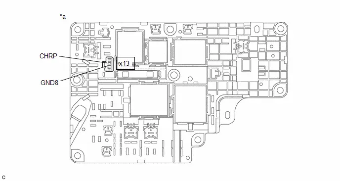
| *a | Component without harness connected (No. 1 Traction Battery Device Box Assembly) | - | - |
Standard Resistance:
 Click Location & Routing(x13) Click Connector(x13)
 | Tester Connection | Condition | Specified Condition | Result |
|---|---|---|---|
| x13-2 (CHRP) - x13-3 (GND8) | -40 to 80°C (-40 to 176°F) | 140 to 290 Ω | Ω |
Post-procedure1
(d) Reconnect the No. 1 traction battery device box assembly connector.
| OK |

| CHECK FOR INTERMITTENT PROBLEMS |
| NG |

| REPLACE NO. 1 TRACTION BATTERY DEVICE BOX ASSEMBLY |
Hybrid/EV Battery Pack Coolant Temperature Sensor System Signal Compare Failure (P19CF62)
DESCRIPTION
The battery ECU assembly monitors the HV battery coolant temperature using the battery pack coolant temperature sensors (thermistors).
The battery ECU assembly detects malfunctions in the battery pack coolant temperature sensors (thermistors) and outputs DTCs.
| DTC No. | Detection Item | DTC Detection Condition | Trouble Area | MIL | Warning Indicate | DTC Output from | Priority | Note |
|---|---|---|---|---|---|---|---|---|
| P19CF62 | Hybrid/EV Battery Pack Coolant Temperature Sensor System Signal Compare Failure | Difference between the values of 4 battery pack coolant temperature sensors is the specified value or more (1 trip detection logic) |
| Comes on | Master Warning: Comes on | HV Battery | A | SAE Code: P19CF |
MONITOR DESCRIPTION
The battery ECU assembly detects malfunctions in the battery pack coolant temperature sensors (thermistors) and outputs DTCs.
MONITOR STRATEGY
| Related DTCs | P19CF (INF P19CF62): Hybrid/EV Battery Pack Coolant Temperature Sensor Signal Compare Failure |
| Required sensors/components | Air Conditioning Thermistor |
| Frequency of operation | Continuous |
| Duration | TMC's intellectual property |
| MIL operation | 1 driving cycle |
| Sequence of operation | None |
TYPICAL ENABLING CONDITIONS
| The monitor will run whenever the following DTCs are not stored | TMC's intellectual property |
| Other conditions belong to TMC's intellectual property | - |
TYPICAL MALFUNCTION THRESHOLDS
| TMC's intellectual property | - |
COMPONENT OPERATING RANGE
| Battery ECU assembly | DTC P19CF (INF P19CF62) is not detected |
CONFIRMATION DRIVING PATTERN
HINT:
-
After repair has been completed, clear the DTC and then check that the Toyota Prius vehicle has returned to normal by performing the following All Readiness check procedure.
Click here

-
When clearing the permanent DTCs, refer to the "CLEAR PERMANENT DTC" procedure.
Click here

- Clear the DTCs (even if no DTCs are stored, perform the clear DTC procedure).
- Turn the ignition switch off and wait for 30 minutes or more.[*1]
-
Turn the ignition switch to ON (READY) and wait for 1 minute or more.[*2]
HINT:
[*1] to [*2]: Normal judgment procedure.
The normal judgment procedure is used to complete DTC judgment and also used when clearing permanent DTCs.
- Enter the following menus: Powertrain / HV Battery / Utility / All Readiness.
-
Check the DTC judgment result.
HINT:
- If the judgment result shows NORMAL, the system is normal.
- If the judgment result shows ABNORMAL, the system has a malfunction.
- If the judgment result shows INCOMPLETE or N/A, perform the normal judgment procedure again.
WIRING DIAGRAM
Refer to the wiring diagram for DTC P0C4211.
Click here

CAUTION / NOTICE / HINT
CAUTION:
Refer to the precautions before inspecting high voltage circuit.
Click here

NOTICE:
-
After the ignition switch is turned off, there may be a waiting time before disconnecting the auxiliary negative (-) battery terminal.
Click here

-
When disconnecting and reconnecting the auxiliary battery.
HINT:
When disconnecting and reconnecting the auxiliary battery, there is an automatic learning function that completes learning when the respective system is used.
Click here

PROCEDURE
| 1. | CHECK DTC OUTPUT (HV BATTERY) |
(a) Check for DTCs.
Powertrain > HV Battery > Trouble Codes| Result | Proceed to |
|---|---|
| "P19CF62" only is output. | A |
| DTCs except "P19CF62" of hybrid battery system are output. | B |
| B |

| GO TO DTC CHART (HYBRID BATTERY SYSTEM) |
|

| 2. | CHECK CONNECTOR CONNECTION CONDITION (BATTERY ECU ASSEMBLY) |
HINT:
Click here

| NG |

| CONNECT SECURELY |
|

| 3. | CHECK NO. 1 TRACTION BATTERY COOLER TUBE (DUCT INLET 1) |
HINT:
Click here

| NG |

| GO TO STEP 6 |
|

| 4. | CHECK NO. 1 TRACTION BATTERY COOLER CONDUCTOR (DUCT OUTLET 1) |
HINT:
Click here

| OK |

| REPLACE BATTERY ECU ASSEMBLY |
|

| 5. | CHECK HARNESS AND CONNECTOR (NO. 1 TRACTION BATTERY COOLER CONDUCTOR (DUCT OUTLET 1) - BATTERY ECU ASSEMBLY) |
HINT:
Click here

| OK |

| REPLACE NO. 1 TRACTION BATTERY COOLER CONDUCTOR |
| NG |

| REPAIR OR REPLACE HARNESS OR CONNECTOR |
| 6. | CHECK HARNESS AND CONNECTOR (NO. 1 TRACTION BATTERY COOLER TUBE (DUCT INLET 1) - BATTERY ECU ASSEMBLY) |
HINT:
Click here

| OK |

| REPLACE NO. 1 TRACTION BATTERY COOLER TUBE |
| NG |

| REPAIR OR REPLACE HARNESS OR CONNECTOR |
Hybrid Battery Stack 2 Cell Voltage Detection Voltage Out of Range (P1A001C,P1A051C,P301A1C)
DESCRIPTION
The HV battery is composed of 72 cells (3.7 V each) in series. The battery ECU assembly monitors the voltage of each HV battery cell to detect malfunctions of the HV battery.
| DTC No. | Detection Item | DTC Detection Condition | Trouble Area | MIL | Warning Indicate | DTC Output from | Priority | Note |
|---|---|---|---|---|---|---|---|---|
| P1A001C | Hybrid Battery Stack 2 Cell Voltage Detection Voltage Out of Range | An open is detected in the HV battery cell voltage detection circuits of the No. 2 HV supply stack sub-assembly. (1 trip detection logic) |
| Comes on | Master Warning: Comes on | HV Battery | A | SAE Code: P1A00 |
| P1A051C | Hybrid Battery Stack 3 Cell Voltage Detection Voltage Out of Range | An open is detected in the HV battery cell voltage detection circuits of the No. 3 HV supply stack sub-assembly. (1 trip detection logic) |
| Comes on | Master Warning: Comes on | HV Battery | A | SAE Code: P1A05 |
| P301A1C | Hybrid Battery Stack 1 Cell Voltage Detection Voltage Out of Range | An open is detected in the HV battery cell voltage detection circuits of the No. 1 HV supply stack sub-assembly. (1 trip detection logic) |
| Comes on | Master Warning: Comes on | HV Battery | A | SAE Code: P301A |
MONITOR DESCRIPTION
If the voltage of an HV battery cell is abnormal, the battery ECU assembly will determine that a malfunction has occurred. When the malfunction detection condition is satisfied, the battery ECU assembly will illuminate the MIL and store a DTC.
MONITOR STRATEGY
| Related DTCs | P1A00 (INF P1A001C), P1A05 (INF P1A051C), P301A (INF P301A1C): Battery voltage detection circuits malfunction |
| Required sensors/components | Battery ECU assembly |
| Frequency of operation | Continuous |
| Duration | TMC's intellectual property |
| MIL operation | 1 driving cycle |
| Sequence of operation | None |
TYPICAL ENABLING CONDITIONS
| The monitor will run whenever the following DTCs are not stored | TMC's intellectual property |
| Other conditions belong to TMC's intellectual property | - |
TYPICAL MALFUNCTION THRESHOLDS
| TMC's intellectual property | - |
COMPONENT OPERATING RANGE
| Battery ECU assembly | DTC P1A00 (INF P1A001C) is not detected DTC P1A05 (INF P1A051C) is not detected DTC P301A (INF P301A1C) is not detected |
CONFIRMATION DRIVING PATTERN
HINT:
-
After repair has been completed, clear the DTC and then check that the Toyota Prius vehicle has returned to normal by performing the following All Readiness check procedure.
Click here

-
When clearing the permanent DTCs, refer to the "CLEAR PERMANENT DTC" procedure.
Click here

- Clear the DTCs (even if no DTCs are stored, perform the clear DTC procedure).
- Turn the ignition switch off and wait for 2 minutes or more.
-
Turn the ignition switch to ON and wait for 10 seconds or more.[*1]
HINT:
[*1]: Normal judgment procedure.
The normal judgment procedure is used to complete DTC judgment and also used when clearing permanent DTCs.
- Enter the following menus: Powertrain / HV Battery / Utility / All Readiness.
-
Check the DTC judgment result.
HINT:
- If the judgment result shows NORMAL, the system is normal.
- If the judgment result shows ABNORMAL, the system has a malfunction.
- If the judgment result shows INCOMPLETE or N/A, perform the normal judgment procedure again.
WIRING DIAGRAM
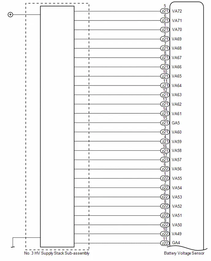


CAUTION / NOTICE / HINT
CAUTION:
Refer to the precautions before inspecting high voltage circuit.
Click here

NOTICE:
-
After the ignition switch is turned off, there may be a waiting time before disconnecting the auxiliary negative (-) battery terminal.
Click here

-
When disconnecting and reconnecting the auxiliary battery.
HINT:
When disconnecting and reconnecting the auxiliary battery, there is an automatic learning function that completes learning when the respective system is used.
Click here

PROCEDURE
| 1. | CHECK DTC OUTPUT (HV BATTERY, HYBRID CONTROL) |
Pre-procedure1
(a) None
Procedure1
(b) Check for DTCs.
Powertrain > HV Battery > Trouble Codes Powertrain > Hybrid Control > Trouble Codes| Result | Proceed to |
|---|---|
| "P1A001C, P1A051C or P301A1C" only is output, or DTCs except the ones in the table below are also output. | A |
| DTCs of hybrid battery system in the table below are output. | B |
| DTCs of hybrid control system in the table below are output. | C |
| System | Relevant DTC | |
|---|---|---|
| Hybrid battery system | P060A47 | Hybrid/EV Battery Energy Control Module Monitoring Processor Watchdog / Safety MCU Failure |
| P060B49 | Hybrid/EV Battery Energy Control Module A/D Processing Internal Electronic Failure | |
| P060687 | Hybrid/EV Battery Energy Control Module Processor to Monitoring Processor Missing Message | |
| P1AC413 | Hybrid/EV Battery Stack 1 Current Interrupt Device Circuit Open | |
| P1AC513 | Hybrid/EV Battery Stack 2 Current Interrupt Device Circuit Open | |
| P1AC613 | Hybrid/EV Battery Stack 3 Current Interrupt Device Circuit Open | |
| P1AC713 | Hybrid/EV Battery Stack 4 Current Interrupt Device Circuit Open | |
| P1AC49E | Hybrid/EV Battery Stack 1 Current Interrupt Device Stuck On | |
| P1AC59E | Hybrid/EV Battery Stack 2 Current Interrupt Device Stuck On | |
| P1AC69E | Hybrid/EV Battery Stack 3 Current Interrupt Device Stuck On | |
| P1AC79E | Hybrid/EV Battery Stack 4 Current Interrupt Device Stuck On | |
| Hybrid control system | P0A1F94 | Hybrid/EV Battery Energy Control Module Unexpected Operation |
Post-procedure1
(c) Turn the ignition switch off.
| B |

| GO TO DTC CHART (HYBRID BATTERY SYSTEM) |
| C |

| GO TO DTC CHART (HYBRID CONTROL SYSTEM) |
|

| 2. | CHECK DTC |
(a) Check the DTCs that were output when the Toyota Prius vehicle was brought to the workshop.
| Result | Proceed to |
|---|---|
| "P1A001C" is also output. | A |
| "P1A051C" is also output. | B |
| "P301A1C" is also output. | C |
| B |

| GO TO STEP 6 |
| C |

| GO TO STEP 9 |
|

| 3. | CHECK CONNECTOR CONNECTION CONDITION (BATTERY VOLTAGE SENSOR CONNECTOR) |
CAUTION:
Be sure to wear insulated gloves and protective goggles.
Pre-procedure1
(a) Check that the service plug grip is not installed.
NOTICE:
After removing the service plug grip, do not turn the ignition switch to ON (READY), unless instructed by the repair manual because this may cause a malfunction.
Procedure1
| (b) Check the connections of the battery voltage sensor connectors. HINT: Click here
OK: The connector is connected securely and there are no contact problems. Result:
|
| |||||||||||||


Post-procedure1
(c) None
| B |

| CONNECT SECURELY |
| C |

| REPLACE NO. 2 HV SUPPLY STACK SUB-ASSEMBLY |
|

| 4. | CHECK FREEZE FRAME DATA |
Pre-procedure1
(a) None
Procedure1
(b) Read the value of freeze frame data items "Hybrid/EV Battery Cell 25 Voltage" through "Hybrid/EV Battery Cell 48 Voltage" for DTC P1A001C and make a note if the value of any is 1.6 V or less.
Powertrain > HV Battery > Trouble CodesPost-procedure1
(c) Turn the ignition switch off.
|

| 5. | CHECK NO. 2 HV SUPPLY STACK SUB-ASSEMBLY (HYBRID BATTERY CELL 25 TO 48 VOLTAGE) |
Click here

| Result | Proceed to |
|---|---|
| The voltage between the terminals is 1.6 V or less. | A |
| Other than above | B |
| A |

| REPLACE NO. 2 HV SUPPLY STACK SUB-ASSEMBLY |
| B |

| REPLACE BATTERY VOLTAGE SENSOR |
| 6. | CHECK CONNECTOR CONNECTION CONDITION (BATTERY VOLTAGE SENSOR CONNECTOR) |
CAUTION:
Be sure to wear insulated gloves and protective goggles.
Pre-procedure1
(a) Check that the service plug grip is not installed.
NOTICE:
After removing the service plug grip, do not turn the ignition switch to ON (READY), unless instructed by the repair manual because this may cause a malfunction.
Procedure1
| (b) Check the connections of the battery voltage sensor connectors. HINT: Click here
OK: The connector is connected securely and there are no contact problems. Result:
|
| |||||||||||||


Post-procedure1
(c) None
| B |

| CONNECT SECURELY |
| C |

| REPLACE NO. 3 HV SUPPLY STACK SUB-ASSEMBLY |
|

| 7. | CHECK FREEZE FRAME DATA |
Pre-procedure1
(a) None
Procedure1
(b) Read the value of freeze frame data items "Hybrid/EV Battery Cell 49 Voltage" through "Hybrid/EV Battery Cell 72 Voltage" for DTC P1A051C and make a note if the value of any is 1.6 V or less.
Powertrain > HV Battery > Trouble CodesPost-procedure1
(c) Turn the ignition switch off.
|

| 8. | CHECK NO. 3 HV SUPPLY STACK SUB-ASSEMBLY (HYBRID BATTERY CELL 49 TO 72 VOLTAGE) |
Click here

| Result | Proceed to |
|---|---|
| The voltage between the terminals is 1.6 V or less. | A |
| Other than above | B |
| A |

| REPLACE NO. 3 HV SUPPLY STACK SUB-ASSEMBLY |
| B |

| REPLACE BATTERY VOLTAGE SENSOR |
| 9. | CHECK CONNECTOR CONNECTION CONDITION (BATTERY VOLTAGE SENSOR CONNECTOR) |
CAUTION:
Be sure to wear insulated gloves and protective goggles.
Pre-procedure1
(a) Check that the service plug grip is not installed.
NOTICE:
After removing the service plug grip, do not turn the ignition switch to ON (READY), unless instructed by the repair manual because this may cause a malfunction.
Procedure1
| (b) Check the connections of the battery voltage sensor connectors. Click here
OK: The connector is connected securely and there are no contact problems. Result:
|
| |||||||||||||


Post-procedure1
(c) None
| B |

| CONNECT SECURELY |
| C |

| REPLACE NO. 1 HV SUPPLY STACK SUB-ASSEMBLY |
|

| 10. | CHECK FREEZE FRAME DATA |
Pre-procedure1
(a) None
Procedure1
(b) Read the value of freeze frame data items "Hybrid/EV Battery Cell 1 Voltage" through "Hybrid/EV Battery Cell 24 Voltage" for DTC P301A1C and make a note if the value of any is 1.6 V or less.
Powertrain > HV Battery > Trouble CodesPost-procedure1
(c) Turn the ignition switch off.
|

| 11. | CHECK NO. 1 HV SUPPLY STACK SUB-ASSEMBLY (HYBRID BATTERY CELL 1 TO 24 VOLTAGE) |
Click here

| Result | Proceed to |
|---|---|
| The voltage between the terminals is 1.6 V or less. | A |
| Other than above | B |
| A |

| REPLACE NO. 1 HV SUPPLY STACK SUB-ASSEMBLY |
| B |

| REPLACE BATTERY VOLTAGE SENSOR |
Hybrid/EV Battery Stack 2 Cell Circuit Voltage Above Threshold (P1A6017,P1A6317,P31AA17)
DESCRIPTION
The HV battery is composed of 72 cells (3.7 V each) in series. The battery ECU assembly monitors the voltage of each HV battery cell to detect malfunctions of the HV battery.
| DTC No. | Detection Item | DTC Detection Condition | Trouble Area | MIL | Warning Indicate | DTC Output from | Priority | Note |
|---|---|---|---|---|---|---|---|---|
| P1A6017 | Hybrid/EV Battery Stack 2 Cell Circuit Voltage Above Threshold | Charging continues to be performed after the voltage of any cell of the No. 2 HV supply stack sub-assembly has exceeded the threshold. (1 trip detection logic) |
| Comes on | Master Warning: Comes on | HV Battery | A | SAE Code: P1A60 |
| P1A6317 | Hybrid/EV Battery Stack 3 Cell Circuit Voltage Above Threshold | Charging continues to be performed after the voltage of any cell of the No. 3 HV supply stack sub-assembly has exceeded the threshold. (1 trip detection logic) |
| Comes on | Master Warning: Comes on | HV Battery | A | SAE Code: P1A63 |
| P31AA17 | Hybrid/EV Battery Stack 1 Cell Circuit Voltage Above Threshold | Charging continues to be performed after the voltage of any cell of the No. 1 HV supply stack sub-assembly has exceeded the threshold. (1 trip detection logic) |
| Comes on | Master Warning: Comes on | HV Battery | A | SAE Code: P31AA |
MONITOR DESCRIPTION
If the battery ECU assembly detects that the voltage of a HV battery cell is excessively high, the battery ECU assembly will illuminate the MIL and store a DTC.
MONITOR STRATEGY
| Related DTCs | P1A60 (INF P1A6017), P1A63 (INF P1A6317), P31AA (INF P31AA17): Cell voltage high |
| Required sensors/components | Battery ECU assembly |
| Frequency of operation | Continuous |
| Duration | TMC's intellectual property |
| MIL operation | 1 driving cycle |
| Sequence of operation | None |
TYPICAL ENABLING CONDITIONS
| The monitor will run whenever the following DTCs are not stored | TMC's intellectual property |
| Other conditions belong to TMC's intellectual property | - |
TYPICAL MALFUNCTION THRESHOLDS
| TMC's intellectual property | - |
COMPONENT OPERATING RANGE
| Battery ECU assembly | DTC P1A60 (INF P1A6017) is not detected DTC P1A63 (INF P1A6317) is not detected DTC P31AA (INF P31AA17) is not detected |
CONFIRMATION DRIVING PATTERN
HINT:
-
After repair has been completed, clear the DTC and then check that the Toyota Prius vehicle has returned to normal by performing the following All Readiness check procedure.
Click here

-
When clearing the permanent DTCs, refer to the "CLEAR PERMANENT DTC" procedure.
Click here

- Clear the DTCs (even if no DTCs are stored, perform the clear DTC procedure).
- Turn the ignition switch off and wait for 2 minutes or more.
-
Drive the Toyota Prius vehicle on urban roads for approximately 10 minutes.[*1]
HINT:
[*1]: Normal judgment procedure.
The normal judgment procedure is used to complete DTC judgment and also used when clearing permanent DTCs.
- Enter the following menus: Powertrain / HV Battery / Utility / All Readiness.
-
Check the DTC judgment result.
HINT:
- If the judgment result shows NORMAL, the system is normal.
- If the judgment result shows ABNORMAL, the system has a malfunction.
- If the judgment result shows INCOMPLETE or N/A, perform the normal judgment procedure again.
CAUTION / NOTICE / HINT
CAUTION:
Refer to the precautions before inspecting high voltage circuit.
Click here

NOTICE:
-
After the ignition switch is turned off, there may be a waiting time before disconnecting the auxiliary negative (-) battery terminal.
Click here

-
When disconnecting and reconnecting the auxiliary battery.
HINT:
When disconnecting and reconnecting the auxiliary battery, there is an automatic learning function that completes learning when the respective system is used.
Click here

PROCEDURE
| 1. | CHECK DTC OUTPUT (HV BATTERY) |
Pre-procedure1
(a) None
Procedure1
(b) Check for DTCs.
Powertrain > HV Battery > Trouble Codes| Result | Proceed to |
|---|---|
| P0C3000 or P31B300 is not output | A |
| P0C3000 or P31B300 is output | B |
Post-procedure1
(c) Turn the ignition switch off.
| B |

| GO TO STEP 3 |
|

| 2. | CHECK DTC |
(a) Check the DTCs that were output when the Toyota Prius vehicle was brought to the workshop.
| Result | Proceed to |
|---|---|
| "P1A6017" is also output. | A |
| "P1A6317" is also output. | B |
| "P31AA17" is also output. | C |
| A |

| REPLACE NO. 2 HV SUPPLY STACK SUB-ASSEMBLY |
| B |

| REPLACE NO. 3 HV SUPPLY STACK SUB-ASSEMBLY |
| C |

| REPLACE NO. 1 HV SUPPLY STACK SUB-ASSEMBLY |
| 3. | CHECK DTC |
(a) Check the DTCs that were output when the Toyota Prius vehicle was brought to the workshop.
| Result | Proceed to |
|---|---|
| "P1A6017" is also output. | A |
| "P1A6317" is also output. | B |
| "P31AA17" is also output. | C |
| B |

| GO TO STEP 5 |
| C |

| GO TO STEP 6 |
|

| 4. | REPLACE NO. 2 HV SUPPLY STACK SUB-ASSEMBLY |
HINT:
Click here

| NEXT |

| REPLACE HYBRID Toyota Prius Vehicle CONTROL ECU |
| 5. | REPLACE NO. 3 HV SUPPLY STACK SUB-ASSEMBLY |
HINT:
Click here

| NEXT |

| REPLACE HYBRID Toyota Prius Vehicle CONTROL ECU |
| 6. | REPLACE NO. 1 HV SUPPLY STACK SUB-ASSEMBLY |
HINT:
Click here

| NEXT |

| REPLACE HYBRID Toyota Prius Vehicle CONTROL ECU |
Hybrid/EV Battery Stack 2 Cell Circuit Voltage Below Threshold (P1A6116,P1A6416,P31AB16)
DESCRIPTION
If the voltage of an HV battery cell is lower than the threshold for a certain amount of time, the battery voltage sensor will interpret this as a malfunction.
| DTC No. | Detection Item | DTC Detection Condition | Trouble Area | MIL | Warning Indicate | DTC Output from | Priority | Note |
|---|---|---|---|---|---|---|---|---|
| P1A6116 | Hybrid/EV Battery Stack 2 Cell Circuit Voltage Below Threshold | The voltage of any cell of the No. 2 HV supply stack sub-assembly has decreased excessively. (1 trip detection logic) |
| Comes on | Master Warning: Comes on | HV Battery | A | SAE Code: P1A61 |
| P1A6416 | Hybrid/EV Battery Stack 3 Cell Circuit Voltage Below Threshold | The voltage of any cell of the No. 3 HV supply stack sub-assembly has decreased excessively. (1 trip detection logic) |
| Comes on | Master Warning: Comes on | HV Battery | A | SAE Code: P1A64 |
| P31AB16 | Hybrid/EV Battery Stack 1 Cell Circuit Voltage Below Threshold | The voltage of any cell of the No. 1 HV supply stack sub-assembly has decreased excessively. (1 trip detection logic) |
| Comes on | Master Warning: Comes on | HV Battery | A | SAE Code: P31AB |
MONITOR DESCRIPTION
If the battery ECU assembly detects that the voltage of any HV battery cell has decreased excessively, the battery ECU assembly will illuminate the MIL and store a DTC.
MONITOR STRATEGY
| Related DTCs | P1A61 (INF P1A6116), P1A64 (INF P1A6416), P31AB (INF P31AB16): Cell voltage low |
| Required sensors/components | Battery ECU assembly |
| Frequency of operation | Continuous |
| Duration | TMC's intellectual property |
| MIL operation | 1 driving cycle |
| Sequence of operation | None |
TYPICAL ENABLING CONDITIONS
| The monitor will run whenever the following DTCs are not stored | TMC's intellectual property |
| Other conditions belong to TMC's intellectual property | - |
TYPICAL MALFUNCTION THRESHOLDS
| TMC's intellectual property | - |
COMPONENT OPERATING RANGE
| Battery ECU assembly | DTC P1A61 (INF P1A6116) is not detected DTC P1A64 (INF P1A6416) is not detected DTC P31AB (INF P31AB16) is not detected |
CONFIRMATION DRIVING PATTERN
HINT:
-
After repair has been completed, clear the DTC and then check that the Toyota Prius vehicle has returned to normal by performing the following All Readiness check procedure.
Click here

-
When clearing the permanent DTCs, refer to the "CLEAR PERMANENT DTC" procedure.
Click here

- Clear the DTCs (even if no DTCs are stored, perform the clear DTC procedure).
- Turn the ignition switch off and wait for 2 minutes or more.
-
Turn the ignition switch to ON and wait for 10 seconds or more.[*1]
HINT:
[*1]: Normal judgment procedure.
The normal judgment procedure is used to complete DTC judgment and also used when clearing permanent DTCs.
- Enter the following menus: Powertrain / HV Battery / Utility / All Readiness.
-
Check the DTC judgment result.
HINT:
- If the judgment result shows NORMAL, the system is normal.
- If the judgment result shows ABNORMAL, the system has a malfunction.
- If the judgment result shows INCOMPLETE or N/A, perform the normal judgment procedure again.
WIRING DIAGRAM
Refer to the wiring diagram for DTC P1A001C.
Click here

CAUTION / NOTICE / HINT
CAUTION:
Refer to the precautions before inspecting high voltage circuit.
Click here

NOTICE:
-
After the ignition switch is turned off, there may be a waiting time before disconnecting the auxiliary negative (-) battery terminal.
Click here

-
When disconnecting and reconnecting the auxiliary battery.
HINT:
When disconnecting and reconnecting the auxiliary battery, there is an automatic learning function that completes learning when the respective system is used.
Click here

PROCEDURE
| 1. | CHECK DTC OUTPUT (HV BATTERY, HYBRID CONTROL) |
Pre-procedure1
(a) None
Procedure1
(b) Check for DTCs.
Powertrain > HV Battery > Trouble Codes Powertrain > Hybrid Control > Trouble Codes| Result | Proceed to |
|---|---|
| "P1A6116, P1A6416 or P31AB16" only is output, or DTCs except the ones in the table below are also output. | A |
| DTCs of hybrid battery system in the table below are output. | B |
| DTCs of hybrid control system in the table below are output. | C |
| System | Relevant DTC | |
|---|---|---|
| Hybrid battery system | P060A47 | Hybrid/EV Battery Energy Control Module Monitoring Processor Watchdog / Safety MCU Failure |
| P060B49 | Hybrid/EV Battery Energy Control Module A/D Processing Internal Electronic Failure | |
| P060687 | Hybrid/EV Battery Energy Control Module Processor to Monitoring Processor Missing Message | |
| P1AC413 | Hybrid/EV Battery Stack 1 Current Interrupt Device Circuit Open | |
| P1AC513 | Hybrid/EV Battery Stack 2 Current Interrupt Device Circuit Open | |
| P1AC613 | Hybrid/EV Battery Stack 3 Current Interrupt Device Circuit Open | |
| P1AC713 | Hybrid/EV Battery Stack 4 Current Interrupt Device Circuit Open | |
| P1AC49E | Hybrid/EV Battery Stack 1 Current Interrupt Device Stuck On | |
| P1AC59E | Hybrid/EV Battery Stack 2 Current Interrupt Device Stuck On | |
| P1AC69E | Hybrid/EV Battery Stack 3 Current Interrupt Device Stuck On | |
| P1AC79E | Hybrid/EV Battery Stack 4 Current Interrupt Device Stuck On | |
| Hybrid control system | P0A1F94 | Hybrid/EV Battery Energy Control Module Unexpected Operation |
Post-procedure1
(c) Turn the ignition switch off.
| B |

| GO TO DTC CHART (HYBRID BATTERY SYSTEM) |
| C |

| GO TO DTC CHART (HYBRID CONTROL SYSTEM) |
|

| 2. | CHECK DTC |
(a) Check the DTCs that were output when the Toyota Prius vehicle was brought to the workshop.
| Result | Proceed to |
|---|---|
| "P1A6116" is also output. | A |
| "P1A6416" is also output. | B |
| "P31AB16" is also output. | C |
| B |

| GO TO STEP 8 |
| C |

| GO TO STEP 13 |
|

| 3. | CHECK CONNECTOR CONNECTION CONDITION (BATTERY VOLTAGE SENSOR CONNECTOR) |
CAUTION:
Be sure to wear insulated gloves and protective goggles.
Pre-procedure1
(a) Check that the service plug grip is not installed.
NOTICE:
After removing the service plug grip, do not turn the ignition switch to ON (READY), unless instructed by the repair manual because this may cause a malfunction.
Procedure1
| (b) Check the connections of the battery voltage sensor connectors. HINT: Click here
OK: The connector is connected securely and there are no contact problems. Result:
|
| |||||||||||||


Post-procedure1
(c) None
| B |

| CONNECT SECURELY |
| C |

| REPLACE NO. 2 HV SUPPLY STACK SUB-ASSEMBLY |
|

| 4. | CHECK FREEZE FRAME DATA |
Pre-procedure1
(a) None
Procedure1
(b) Read the value of freeze frame data items "Hybrid/EV Battery Cell 25 voltage" through "Hybrid/EV Battery Cell 48 voltage" for DTC P1A6116 and make a note if the value of any is 1.6 V or less.
Powertrain > HV Battery > Trouble CodesPost-procedure1
(c) Turn the ignition switch off.
|

| 5. | CHECK NO. 2 HV SUPPLY STACK SUB-ASSEMBLY (HYBRID BATTERY CELL 25 TO 48 VOLTAGE) |
Click here

| Result | Proceed to |
|---|---|
| The voltage between the terminals is 1.6 V or less. | A |
| Other than above | B |
| B |

| REPLACE BATTERY VOLTAGE SENSOR |
|

| 6. | CHECK BATTERY VOLTAGE SENSOR (VA25 - VA48) |
Click here

| Result | Proceed to |
|---|---|
| The resistance between the terminals is 50 kΩ or more. | A |
| Other than above | B |
| A |

| REPLACE NO. 2 HV SUPPLY STACK SUB-ASSEMBLY |
|

| 7. | REPLACE NO. 2 HV SUPPLY STACK SUB-ASSEMBLY |
HINT:
Click here

| NEXT |

| REPLACE BATTERY VOLTAGE SENSOR |
| 8. | CHECK CONNECTOR CONNECTION CONDITION (BATTERY VOLTAGE SENSOR CONNECTOR) |
CAUTION:
Be sure to wear insulated gloves and protective goggles.
Pre-procedure1
(a) Check that the service plug grip is not installed.
NOTICE:
After removing the service plug grip, do not turn the ignition switch to ON (READY), unless instructed by the repair manual because this may cause a malfunction.
Procedure1
| (b) Check the connections of the battery voltage sensor connectors. HINT: Click here
OK: The connector is connected securely and there are no contact problems. Result:
|
| |||||||||||||

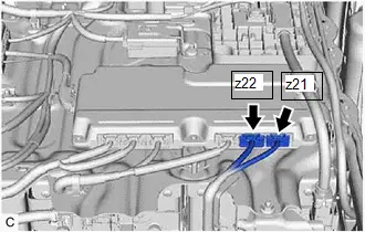
Post-procedure1
(c) None
| B |

| CONNECT SECURELY |
| C |

| REPLACE NO. 3 HV SUPPLY STACK SUB-ASSEMBLY |
|

| 9. | CHECK FREEZE FRAME DATA |
Pre-procedure1
(a) None
Procedure1
(b) Read the value of freeze frame data items "Hybrid/EV Battery Cell 49 voltage" through "Hybrid/EV Battery Cell 72 voltage" for DTC P1A6416 and make a note if the value of any is 1.6 V or less.
Powertrain > HV Battery > Trouble CodesPost-procedure1
(c) Turn the ignition switch off.
|

| 10. | CHECK NO. 3 HV SUPPLY STACK SUB-ASSEMBLY (HYBRID BATTERY CELL 49 TO 72 VOLTAGE) |
Click here

| Result | Proceed to |
|---|---|
| The voltage between the terminals is 1.6 V or less. | A |
| Other than above | B |
| B |

| REPLACE BATTERY VOLTAGE SENSOR |
|

| 11. | CHECK BATTERY VOLTAGE SENSOR (VA49 - VA72) |
Click here

| Result | Proceed to |
|---|---|
| The resistance between the terminals is 50 kΩ or more. | A |
| Other than above | B |
| A |

| REPLACE NO. 3 HV SUPPLY STACK SUB-ASSEMBLY |
|

| 12. | REPLACE NO. 3 HV SUPPLY STACK SUB-ASSEMBLY |
HINT:
Click here

| NEXT |

| REPLACE BATTERY VOLTAGE SENSOR |
| 13. | CHECK CONNECTOR CONNECTION CONDITION (BATTERY VOLTAGE SENSOR CONNECTOR) |
CAUTION:
Be sure to wear insulated gloves and protective goggles.
Pre-procedure1
(a) Check that the service plug grip is not installed.
NOTICE:
After removing the service plug grip, do not turn the ignition switch to ON (READY), unless instructed by the repair manual because this may cause a malfunction.
Procedure1
| (b) Check the connections of the battery voltage sensor connectors. HINT: Click here
OK: The connector is connected securely and there are no contact problems. Result:
|
| |||||||||||||


Post-procedure1
(c) None
| B |

| CONNECT SECURELY |
| C |

| REPLACE NO. 1 HV SUPPLY STACK SUB-ASSEMBLY |
|

| 14. | CHECK FREEZE FRAME DATA |
Pre-procedure1
(a) None
Procedure1
(b) Read the value of freeze frame data items "Hybrid/EV Battery Cell 1 voltage" through "Hybrid/EV Battery Cell 24 voltage" for DTC P31AB16 and make a note if the value of any is 1.6 V or less.
Powertrain > HV Battery > Trouble CodesPost-procedure1
(c) Turn the ignition switch off.
|

| 15. | CHECK NO. 1 HV SUPPLY STACK SUB-ASSEMBLY (HYBRID BATTERY CELL 1 TO 24 VOLTAGE) |
Click here

| Result | Proceed to |
|---|---|
| The voltage between the terminals is 1.6 V or less. | A |
| Other than above | B |
| B |

| REPLACE BATTERY VOLTAGE SENSOR |
|

| 16. | CHECK BATTERY VOLTAGE SENSOR (VA1 - VA24) |
Click here

| Result | Proceed to |
|---|---|
| The resistance between the terminals is 50 kΩ or more. | A |
| Other than above | B |
| A |

| REPLACE NO. 1 HV SUPPLY STACK SUB-ASSEMBLY |
|

| 17. | REPLACE NO. 1 HV SUPPLY STACK SUB-ASSEMBLY |
HINT:
Click here

| NEXT |

| REPLACE BATTERY VOLTAGE SENSOR |
Hybrid/EV Battery Stack 1 Delta SOC High (Extreme) (P1A8100,P1A8600,P1A8B00)
DESCRIPTION
The HV battery is composed of 72 cells (3.7 V each) in series. The battery ECU assembly monitors the difference in capacity of each HV battery cell to detect malfunctions of the HV battery.
| DTC No. | Detection Item | DTC Detection Condition | Trouble Area | MIL | Warning Indicate | DTC Output from | Priority | Note |
|---|---|---|---|---|---|---|---|---|
| P1A8100 | Hybrid/EV Battery Stack 1 Delta SOC High (Extreme) | The difference in capacity of each cell of the No. 1 HV supply stack sub-assembly exceeds the specified value excessively. (1 trip detection logic) |
| Comes on | Master Warning: Comes on | HV Battery | A | SAE Code: P1A81 |
| P1A8600 | Hybrid/EV Battery Stack 2 Delta SOC High (Extreme) | The difference in capacity of each cell of the No. 2 HV supply stack sub-assembly exceeds the specified value excessively. (1 trip detection logic) |
| Comes on | Master Warning: Comes on | HV Battery | A | SAE Code: P1A86 |
| P1A8B00 | Hybrid/EV Battery Stack 3 Delta SOC High (Extreme) | The difference in capacity of each cell of the No. 3 HV supply stack sub-assembly exceeds the specified value excessively. (1 trip detection logic) |
| Comes on | Master Warning: Comes on | HV Battery | A | SAE Code: P1A8B |
HINT:
These DTCs can be stored after clearing the DTCs and driving the Toyota Prius vehicle for approximately 12 minutes.
MONITOR DESCRIPTION
If the battery ECU assembly detects that the difference in capacity of each HV battery cell exceeds the specified value (excessively), the battery ECU assembly illuminates the MIL and stores a DTC.
MONITOR STRATEGY
| Related DTCs | P1A81 (INF P1A8100), P1A86 (INF P1A8600), P1A8B (INF P1A8B00): Battery cell malfunction |
| Required sensors/components | Battery ECU assembly |
| Frequency of operation | Continuous |
| Duration | TMC's intellectual property |
| MIL operation | 1 driving cycle |
| Sequence of operation | None |
TYPICAL ENABLING CONDITIONS
| The monitor will run whenever the following DTCs are not stored | TMC's intellectual property |
| Other conditions belong to TMC's intellectual property | - |
TYPICAL MALFUNCTION THRESHOLDS
| TMC's intellectual property | - |
COMPONENT OPERATING RANGE
| Battery ECU assembly | DTC P1A81 (INF P1A8100) is not detected DTC P1A86 (INF P1A8600) is not detected DTC P1A8B (INF P1A8B00) is not detected |
CONFIRMATION DRIVING PATTERN
HINT:
-
After repair has been completed, clear the DTC and then check that the Toyota Prius vehicle has returned to normal by performing the following All Readiness check procedure.
Click here

-
When clearing the permanent DTCs, refer to the "CLEAR PERMANENT DTC" procedure.
Click here

- Clear the DTCs (even if no DTCs are stored, perform the clear DTC procedure).
- Turn the ignition switch off and wait for 2 minutes or more.
-
Drive the Toyota Prius vehicle on urban roads for approximately 12 minutes.[*1]
HINT:
[*1]: Normal judgment procedure.
The normal judgment procedure is used to complete DTC judgment and also used when clearing permanent DTCs.
- Enter the following menus: Powertrain / HV Battery / Utility / All Readiness.
-
Check the DTC judgment result.
HINT:
- If the judgment result shows NORMAL, the system is normal.
- If the judgment result shows ABNORMAL, the system has a malfunction.
- If the judgment result shows INCOMPLETE or N/A, perform the normal judgment procedure again.
WIRING DIAGRAM
Refer to the wiring diagram for DTC P1A001C.
Click here

CAUTION / NOTICE / HINT
CAUTION:
Refer to the precautions before inspecting high voltage circuit.
Click here

NOTICE:
-
After the ignition switch is turned off, there may be a waiting time before disconnecting the auxiliary negative (-) battery terminal.
Click here

-
When disconnecting and reconnecting the auxiliary battery.
HINT:
When disconnecting and reconnecting the auxiliary battery, there is an automatic learning function that completes learning when the respective system is used.
Click here

PROCEDURE
| 1. | CHECK DTC OUTPUT (HV BATTERY, HYBRID CONTROL) |
Pre-procedure1
(a) None
Procedure1
(b) Check for DTCs.
Powertrain > HV Battery > Trouble Codes Powertrain > Hybrid Control > Trouble Codes| Result | Proceed to |
|---|---|
| "P1A8100, P1A8600 or P1A8B00" only is output, or DTCs except the ones in the table below are also output. | A |
| DTCs of hybrid battery system in the table below are output. | B |
| DTCs of hybrid control system in the table below are output. | C |
| System | Relevant DTC | |
|---|---|---|
| Hybrid battery system | P060A47 | Hybrid/EV Battery Energy Control Module Monitoring Processor Watchdog / Safety MCU Failure |
| P060B49 | Hybrid/EV Battery Energy Control Module A/D Processing Internal Electronic Failure | |
| P060687 | Hybrid/EV Battery Energy Control Module Processor to Monitoring Processor Missing Message | |
| P0ABF28 | Hybrid/EV Battery Current Sensor "A" Signal Bias Level Out of Range / Zero Adjustment Failure | |
| P0ABF2A | Hybrid/EV Battery Current Sensor "A" Signal Stuck In Range | |
| P1AC413 | Hybrid/EV Battery Stack 1 Current Interrupt Device Circuit Open | |
| P1AC513 | Hybrid/EV Battery Stack 2 Current Interrupt Device Circuit Open | |
| P1AC613 | Hybrid/EV Battery Stack 3 Current Interrupt Device Circuit Open | |
| P1AC713 | Hybrid/EV Battery Stack 4 Current Interrupt Device Circuit Open | |
| P1AC49E | Hybrid/EV Battery Stack 1 Current Interrupt Device Stuck On | |
| P1AC59E | Hybrid/EV Battery Stack 2 Current Interrupt Device Stuck On | |
| P1AC69E | Hybrid/EV Battery Stack 3 Current Interrupt Device Stuck On | |
| P1AC79E | Hybrid/EV Battery Stack 4 Current Interrupt Device Stuck On | |
| P1CBB12 | Hybrid/EV Battery Current Sensor Power Supply Circuit Short to Auxiliary Battery | |
| P1CBB14 | Hybrid/EV Battery Current Sensor Power Supply Circuit Short to Ground or Open | |
| P1CC81E | Hybrid/EV Battery Stack 1 Voltage Difference Out of Range | |
| P1CC91E | Hybrid/EV Battery Stack 2 Voltage Difference Out of Range | |
| P1CCA1E | Hybrid/EV Battery Stack 3 Voltage Difference Out of Range | |
| P1CCB1E | Hybrid/EV Battery Stack 4 Voltage Difference Out of Range | |
| Hybrid control system | P0B231C | Hybrid/EV Battery "A" Voltage Sensor Voltage Out of Range |
| P1C2D62 | Hybrid/EV Battery "A" Voltage Sensor/ Boosting Converter Voltage Sensor "A" Signal Compare Failure | |
Post-procedure1
(c) Turn the ignition switch off.
| B |

| GO TO DTC CHART (HYBRID BATTERY SYSTEM) |
| C |

| GO TO DTC CHART (HYBRID CONTROL SYSTEM) |
|

| 2. | CHECK DTC |
(a) Check the DTCs that were output when the Toyota Prius vehicle was brought to the workshop.
| Result | Proceed to |
|---|---|
| "P1A8100" is also output. | A |
| "P1A8600" is also output. | B |
| "P1A8B00" is also output. | C |
| B |

| GO TO STEP 7 |
| C |

| GO TO STEP 11 |
|

| 3. | CHECK FREEZE FRAME DATA |
Pre-procedure1
(a) None
Procedure1
(b) Read the value of freeze frame data items "Hybrid/EV Battery Cell 1 Voltage" through "Hybrid/EV Battery Cell 24 Voltage" for DTC P1A8100 and make a note if the value of any is the lowest voltage value.
Powertrain > HV Battery > Trouble CodesPost-procedure1
(c) Turn the ignition switch off.
|

| 4. | CHECK BATTERY VOLTAGE SENSOR (VA1 - VA24) |
Click here

| Result | Proceed to |
|---|---|
| The resistance between the terminals is 50 kΩ or more. | A |
| Other than above | B |
| B |

| REPLACE BATTERY VOLTAGE SENSOR |
|

| 5. | CHECK TOTAL DISTANCE DRIVEN |
(a) Read the odometer to check the total distance the Toyota Prius vehicle has been driven.
| Result | Proceed to | |
|---|---|---|
| Total distance driven is less than 200000 km (124280 mile) | A | |
| Total distance driven is 200000 km (124280 mile) or more | Current total distance driven - total distance driven when service plug grip replaced = less than 200000 km (124280 mile) *1 | |
| Other than above | B | |
HINT:
*1: If the service plug grip has been replaced, use the total distance driven since it was replaced.
| A |

| REPLACE NO. 1 HV SUPPLY STACK SUB-ASSEMBLY |
|

| 6. | REPLACE NO. 1 HV SUPPLY STACK SUB-ASSEMBLY |
HINT:
Click here

| NEXT |

| REPLACE SERVICE PLUG GRIP |
| 7. | CHECK FREEZE FRAME DATA |
Pre-procedure1
(a) None
Procedure1
(b) Read the value of freeze frame data items "Hybrid/EV Battery Cell 25 Voltage" through "Hybrid/EV Battery Cell 48 Voltage" for DTC P1A8600 and make a note if the value of any is the lowest voltage value.
Powertrain > HV Battery > Trouble CodesPost-procedure1
(c) Turn the ignition switch off.
|

| 8. | CHECK BATTERY VOLTAGE SENSOR (VA25 - VA48) |
Click here

| Result | Proceed to |
|---|---|
| The resistance between the terminals is 50 kΩ or more. | A |
| Other than above | B |
| B |

| REPLACE BATTERY VOLTAGE SENSOR |
|

| 9. | CHECK TOTAL DISTANCE DRIVEN |
(a) Read the odometer to check the total distance the Toyota Prius vehicle has been driven.
| Result | Proceed to | |
|---|---|---|
| Total distance driven is less than 200000 km (124280 mile) | A | |
| Total distance driven is 200000 km (124280 mile) or more | Current total distance driven - total distance driven when service plug grip replaced = less than 200000 km (124280 mile) *1 | |
| Other than above | B | |
HINT:
*1: If the service plug grip has been replaced, use the total distance driven since it was replaced.
| A |

| REPLACE NO. 2 HV SUPPLY STACK SUB-ASSEMBLY |
|

| 10. | REPLACE NO. 2 HV SUPPLY STACK SUB-ASSEMBLY |
HINT:
Click here

| NEXT |

| REPLACE SERVICE PLUG GRIP |
| 11. | CHECK FREEZE FRAME DATA |
Pre-procedure1
(a) None
Procedure1
(b) Read the value of freeze frame data items "Hybrid/EV Battery Cell 49 Voltage" through "Hybrid/EV Battery Cell 72 Voltage" for DTC P1A8B00 and make a note if the value of any is the lowest voltage value.
Powertrain > HV Battery > Trouble CodesPost-procedure1
(c) Turn the ignition switch off.
|

| 12. | CHECK BATTERY VOLTAGE SENSOR (VA49 - VA72) |
Click here

| Result | Proceed to |
|---|---|
| The resistance between the terminals is 50 kΩ or more. | A |
| Other than above | B |
| B |

| REPLACE BATTERY VOLTAGE SENSOR |
|

| 13. | CHECK TOTAL DISTANCE DRIVEN |
(a) Read the odometer to check the total distance the Toyota Prius vehicle has been driven.
| Result | Proceed to | |
|---|---|---|
| Total distance driven is less than 200000 km (124280 mile) | A | |
| Total distance driven is 200000 km (124280 mile) or more | Current total distance driven - total distance driven when service plug grip replaced = less than 200000 km (124280 mile) *1 | |
| Other than above | B | |
HINT:
*1: If the service plug grip has been replaced, use the total distance driven since it was replaced.
| A |

| REPLACE NO. 3 HV SUPPLY STACK SUB-ASSEMBLY |
|

| 14. | REPLACE NO. 3 HV SUPPLY STACK SUB-ASSEMBLY |
HINT:
Click here

| NEXT |

| REPLACE SERVICE PLUG GRIP |
Hybrid/EV Battery Stack 1 Current Interrupt Device Circuit Open (P1AC413-P1AC613)
DESCRIPTION
The battery ECU assembly restricts charging and discharging of the HV battery and stores a DTC when a current interrupt device (CID) located in an HV battery cell has operated and the high voltage circuit is disconnected.
| DTC No. | Detection Item | DTC Detection Condition | Trouble Area | MIL | Warning Indicate | DTC Output from | Priority | Note |
|---|---|---|---|---|---|---|---|---|
| P1AC413 | Hybrid/EV Battery Stack 1 Current Interrupt Device Circuit Open | A shut-off by a CID occurs. (1 trip detection logic) |
| Comes on | Master Warning: Comes on | HV Battery | A | SAE Code: P1AC4 |
| P1AC513 | Hybrid/EV Battery Stack 2 Current Interrupt Device Circuit Open | A shut-off by a CID occurs. (1 trip detection logic) |
| Comes on | Master Warning: Comes on | HV Battery | A | SAE Code: P1AC5 |
| P1AC613 | Hybrid/EV Battery Stack 3 Current Interrupt Device Circuit Open | A shut-off by a CID occurs. (1 trip detection logic) |
| Comes on | Master Warning: Comes on | HV Battery | A | SAE Code: P1AC6 |
MONITOR DESCRIPTION
If a current interrupt device (CID) located in a HV battery cell is shut off, the battery ECU assembly prohibits charging and discharging, illuminates the MIL and stores a DTC.
MONITOR STRATEGY
| Related DTCs | P1AC4 (INF P1AC413): Hybrid/EV Battery Cell Voltage Low Pack 1 Stack "A" at CID interception P1AC5 (INF P1AC513): Hybrid/EV Battery Cell Voltage Low Pack 1 Stack "B" at CID interception P1AC6 (INF P1AC613): Hybrid/EV Battery Cell Voltage Low Pack 1 Stack "C" at CID interception |
| Required sensors/components | HV battery |
| Frequency of operation | Continuous |
| Duration | TMC's intellectual property |
| MIL operation | 1 driving cycle |
| Sequence of operation | None |
TYPICAL ENABLING CONDITIONS
| The monitor will run whenever the following DTCs are not stored | TMC's intellectual property |
| Other conditions belong to TMC's intellectual property | - |
TYPICAL MALFUNCTION THRESHOLDS
| TMC's intellectual property | - |
COMPONENT OPERATING RANGE
| Battery ECU assembly | DTC P1AC4 (INF P1AC413) is not detected DTC P1AC5 (INF P1AC513) is not detected DTC P1AC6 (INF P1AC613) is not detected |
CONFIRMATION DRIVING PATTERN
HINT:
-
After repair has been completed, clear the DTC and then check that the Toyota Prius vehicle has returned to normal by performing the following All Readiness check procedure.
Click here

-
When clearing the permanent DTCs, refer to the "CLEAR PERMANENT DTC" procedure.
Click here

- Clear the DTCs (even if no DTCs are stored, perform the clear DTC procedure).
- Turn the ignition switch off and wait for 2 minutes or more.
- Turn the ignition switch to ON and wait for 10 seconds or more.[*1]
- Turn the ignition switch off and wait for 2 minutes or more.[*2]
-
Turn the ignition switch to ON (READY) and wait for 30 minutes or more.[*3]
HINT:
[*1] to [*3]: Normal judgment procedure.
The normal judgment procedure is used to complete DTC judgment and also used when clearing permanent DTCs.
- Enter the following menus: Powertrain / HV Battery / Utility / All Readiness.
-
Check the DTC judgment result.
HINT:
- If the judgment result shows NORMAL, the system is normal.
- If the judgment result shows ABNORMAL, the system has a malfunction.
- If the judgment result shows INCOMPLETE or N/A, perform the normal judgment procedure again.
WIRING DIAGRAM
Refer to the wiring diagram for DTC P1A001C.
Click here

CAUTION / NOTICE / HINT
CAUTION:
Refer to the precautions before inspecting high voltage circuit.
Click here

NOTICE:
- Be sure to check that the applicable DTC is output from the hybrid battery system.
-
After the ignition switch is turned off, there may be a waiting time before disconnecting the auxiliary negative (-) battery terminal.
Click here

-
When disconnecting and reconnecting the auxiliary battery.
HINT:
When disconnecting and reconnecting the auxiliary battery, there is an automatic learning function that completes learning when the respective system is used.
Click here

- Do not turn the ignition switch to ON (READY) until the repair is completed.
PROCEDURE
| 1. | CHECK DTC OUTPUT (HV BATTERY, HYBRID CONTROL) |
Pre-procedure1
(a) None
Procedure1
(b) Check for DTCs.
Powertrain > HV Battery > Trouble Codes Powertrain > Hybrid Control > Trouble Codes| Result | Proceed to |
|---|---|
| "P1AC413, P1AC513 or P1AC613" only is output, or DTCs except the ones in the table below are also output. | A |
| DTCs of hybrid battery system in the table below are output. | B |
| DTCs of hybrid control system in the table below are output. | C |
| System | Relevant DTC | |
|---|---|---|
| Hybrid battery system | P060A47 | Hybrid/EV Battery Energy Control Module Monitoring Processor Watchdog / Safety MCU Failure |
| P060B49 | Hybrid/EV Battery Energy Control Module A/D Processing Internal Electronic Failure | |
| P060687 | Hybrid/EV Battery Energy Control Module Processor to Monitoring Processor Missing Message | |
| Hybrid control system | P0A1F94 | Hybrid/EV Battery Energy Control Module Unexpected Operation |
Post-procedure1
(c) Turn the ignition switch off.
| B |

| GO TO DTC CHART (HYBRID BATTERY SYSTEM) |
| C |

| GO TO DTC CHART (HYBRID CONTROL SYSTEM) |
|

| 2. | CHECK DTC |
(a) Check the DTCs that were output when the Toyota Prius vehicle was brought to the workshop.
| Result | Proceed to |
|---|---|
| "P1AC413" is also output. | A |
| "P1AC513" is also output. | B |
| "P1AC613" is also output. | C |
| B |

| GO TO STEP 8 |
| C |

| GO TO STEP 13 |
|

| 3. | READ VALUE USING GTS (HYBRID/EV BATTERY CELL 1 TO 24 VOLTAGE) |
Pre-procedure1
(a) None
Procedure1
(b) Read the value of Data List items "Hybrid/EV battery cell 1 voltage" through "Hybrid/EV battery cell 24 voltage" and make a note if the value of any is 1.6 V or less.
Powertrain > HV Battery > Data List| Tester Display |
|---|
| Hybrid/EV Battery Cell 1 Voltage |
| Hybrid/EV Battery Cell 2 Voltage |
| Hybrid/EV Battery Cell 3 Voltage |
| Hybrid/EV Battery Cell 4 Voltage |
| Hybrid/EV Battery Cell 5 Voltage |
| Hybrid/EV Battery Cell 6 Voltage |
| Hybrid/EV Battery Cell 7 Voltage |
| Hybrid/EV Battery Cell 8 Voltage |
| Hybrid/EV Battery Cell 9 Voltage |
| Hybrid/EV Battery Cell 10 Voltage |
| Hybrid/EV Battery Cell 11 Voltage |
| Hybrid/EV Battery Cell 12 Voltage |
| Hybrid/EV Battery Cell 13 Voltage |
| Hybrid/EV Battery Cell 14 Voltage |
| Hybrid/EV Battery Cell 15 Voltage |
| Hybrid/EV Battery Cell 16 Voltage |
| Hybrid/EV Battery Cell 17 Voltage |
| Hybrid/EV Battery Cell 18 Voltage |
| Hybrid/EV Battery Cell 19 Voltage |
| Hybrid/EV Battery Cell 20 Voltage |
| Hybrid/EV Battery Cell 21 Voltage |
| Hybrid/EV Battery Cell 22 Voltage |
| Hybrid/EV Battery Cell 23 Voltage |
| Hybrid/EV Battery Cell 24 Voltage |
Post-procedure1
(c) Turn the ignition switch off.
|

| 4. | CHECK CONNECTOR CONNECTION CONDITION (BATTERY VOLTAGE SENSOR CONNECTOR) |
CAUTION:
Be sure to wear insulated gloves and protective goggles.
Pre-procedure1
(a) Check that the service plug grip is not installed.
NOTICE:
After removing the service plug grip, do not turn the ignition switch to ON (READY), unless instructed by the repair manual because this may cause a malfunction.
Procedure1
| (b) Check the connections of the battery voltage sensor connector. HINT: Click here
OK: The connector is connected securely and there are no contact problems. Result:
|
| |||||||||||||


Post-procedure1
(c) None
| B |

| CONNECT SECURELY |
| C |

| REPLACE NO. 1 HV SUPPLY STACK SUB-ASSEMBLY |
|

| 5. | CHECK NO. 1 HV SUPPLY STACK SUB-ASSEMBLY (HYBRID BATTERY CELL 1 TO 24 VOLTAGE) |
Click here

| Result | Proceed to |
|---|---|
| The voltage between the terminals is 1.6 V or less. | A |
| Other than above | B |
| B |

| REPLACE BATTERY VOLTAGE SENSOR |
|

| 6. | CHECK BATTERY VOLTAGE SENSOR (VA1 - VA24) |
NOTICE:
Make sure to use tester probes with a diameter of approximately 0.5 mm (0.0197 in.) when measuring the voltage.
Pre-procedure1
(a) Remove the battery voltage sensor.
HINT:
Click here

Procedure1
(b) Measure the voltage according to the value(s) in the table below.
HINT:
Only inspect the terminals of the battery voltage sensor which correspond to the HV battery cells which measured 1.6 V or less in the previous step.

| *a | Component without harness connected (Battery Voltage Sensor) | - | - |
Standard Voltage:
| Hybrid Battery Cell | Tester Connection (Tester Probe Polarity) | Condition | Specified Condition |
|---|---|---|---|
| 1 | z18-6 (GA0) (-) - z18-5 (VA1) ( ) | Always | 0.3 to 1.0 V |
| 2 | z18-5 (VA1) (-) - z18-4 (VA2) ( ) | Always | 0.3 to 1.0 V |
| 3 | z18-4 (VA2) (-) - z18-1 (VA3) ( ) | Always | 0.3 to 1.0 V |
| 4 | z18-1 (VA3) (-) - z18-3 (VA4) ( ) | Always | 0.3 to 1.0 V |
| 5 | z18-3 (VA4) (-) - z17-27 (VA5) ( ) | Always | 0.3 to 1.0 V |
| 6 | z17-27 (VA5) (-) - z17-17 (VA6) ( ) | Always | 0.3 to 1.0 V |
| 7 | z17-17 (VA6) (-) - z17-16 (VA7) ( ) | Always | 0.3 to 1.0 V |
| 8 | z17-16 (VA7) (-) - z17-4 (VA8) ( ) | Always | 0.3 to 1.0 V |
| 9 | z17-4 (VA8) (-) - z17-3 (VA9) ( ) | Always | 0.3 to 1.0 V |
| 10 | z17-3 (VA9) (-) - z17-15 (VA10) ( ) | Always | 0.3 to 1.0 V |
| 11 | z17-15 (VA10) (-) - z17-14 (VA11) ( ) | Always | 0.3 to 1.0 V |
| 12 | z17-14 (VA11) (-) - z17-13 (VA12) ( ) | Always | 0.3 to 1.0 V |
| 13 | z17-12 (GA1) (-) - z17-23 (VA13) ( ) | Always | 0.3 to 1.0 V |
| 14 | z17-23 (VA13) (-) - z17-11 (VA14) ( ) | Always | 0.3 to 1.0 V |
| 15 | z17-11 (VA14) (-) - z17-10 (VA15) ( ) | Always | 0.3 to 1.0 V |
| 16 | z17-10 (VA15) (-) - z17-9 (VA16) ( ) | Always | 0.3 to 1.0 V |
| 17 | z17-9 (VA16) (-) - z17-8 (VA17) ( ) | Always | 0.3 to 1.0 V |
| 18 | z17-8 (VA17) (-) - z17-20 (VA18) ( ) | Always | 0.3 to 1.0 V |
| 19 | z17-20 (VA18) (-) - z17-7 (VA19) ( ) | Always | 0.3 to 1.0 V |
| 20 | z17-7 (VA19) (-) - z17-2 (VA20) ( ) | Always | 0.3 to 1.0 V |
| 21 | z17-2 (VA20) (-) - z17-1 (VA21) ( ) | Always | 0.3 to 1.0 V |
| 22 | z17-1 (VA21) (-) - z17-6 (VA22) ( ) | Always | 0.3 to 1.0 V |
| 23 | z17-6 (VA22) (-) - z17-5 (VA23) ( ) | Always | 0.3 to 1.0 V |
| 24 | z17-5 (VA23) (-) - z17-18 (VA24) ( ) | Always | 0.3 to 1.0 V |
NOTICE:
- Make sure to check the polarity of each terminal (positive ( ) or negative (-)) before connecting a tester.
- Be sure to set the Toyota electrical tester to diode range when performing this test.
- Read the voltage after the value has stabilized.
- In order to avoid damaging the terminals of the battery voltage sensor, make sure to use tester probes with a diameter of approximately 0.5 mm (0.0197 in.) when measuring the voltage of the battery voltage sensor.
| Result | Proceed to |
|---|---|
| The voltage between the terminals is 0.3 to 1.0 V. | A |
| Other than above | B |
Post-procedure1
(c) Install the battery voltage sensor.
| A |

| REPLACE NO. 1 HV SUPPLY STACK SUB-ASSEMBLY |
|

| 7. | REPLACE NO. 1 HV SUPPLY STACK SUB-ASSEMBLY |
HINT:
Click here

| NEXT |

| REPLACE BATTERY VOLTAGE SENSOR |
| 8. | READ VALUE USING GTS (HYBRID/EV BATTERY CELL 25 TO 48 VOLTAGE) |
Pre-procedure1
(a) None
Procedure1
(b) Read the value of Data List items "Hybrid/EV battery cell 25 voltage" through "Hybrid/EV battery cell 48 voltage" and make a note if the value of any is 1.6 V or less.
Powertrain > HV Battery > Data List| Tester Display |
|---|
| Hybrid/EV Battery Cell 25 Voltage |
| Hybrid/EV Battery Cell 26 Voltage |
| Hybrid/EV Battery Cell 27 Voltage |
| Hybrid/EV Battery Cell 28 Voltage |
| Hybrid/EV Battery Cell 29 Voltage |
| Hybrid/EV Battery Cell 30 Voltage |
| Hybrid/EV Battery Cell 31 Voltage |
| Hybrid/EV Battery Cell 32 Voltage |
| Hybrid/EV Battery Cell 33 Voltage |
| Hybrid/EV Battery Cell 34 Voltage |
| Hybrid/EV Battery Cell 35 Voltage |
| Hybrid/EV Battery Cell 36 Voltage |
| Hybrid/EV Battery Cell 37 Voltage |
| Hybrid/EV Battery Cell 38 Voltage |
| Hybrid/EV Battery Cell 39 Voltage |
| Hybrid/EV Battery Cell 40 Voltage |
| Hybrid/EV Battery Cell 41 Voltage |
| Hybrid/EV Battery Cell 42 Voltage |
| Hybrid/EV Battery Cell 43 Voltage |
| Hybrid/EV Battery Cell 44 Voltage |
| Hybrid/EV Battery Cell 45 Voltage |
| Hybrid/EV Battery Cell 46 Voltage |
| Hybrid/EV Battery Cell 47 Voltage |
| Hybrid/EV Battery Cell 48 Voltage |
Post-procedure1
(c) Turn the ignition switch off.
|

| 9. | CHECK CONNECTOR CONNECTION CONDITION (BATTERY VOLTAGE SENSOR CONNECTOR) |
CAUTION:
Be sure to wear insulated gloves and protective goggles.
Pre-procedure1
(a) Check that the service plug grip is not installed.
NOTICE:
After removing the service plug grip, do not turn the ignition switch to ON (READY), unless instructed by the repair manual because this may cause a malfunction.
Procedure1
| (b) Check the connections of the battery voltage sensor connectors. HINT: Click here
OK: The connector is connected securely and there are no contact problems. Result:
|
| |||||||||||||


Post-procedure1
(c) None
| B |

| CONNECT SECURELY |
| C |

| REPLACE NO. 2 HV SUPPLY STACK SUB-ASSEMBLY |
|

| 10. | CHECK NO. 2 HV SUPPLY STACK SUB-ASSEMBLY (HYBRID BATTERY CELL 25 TO 48 VOLTAGE) |
Click here

| Result | Proceed to |
|---|---|
| The voltage between the terminals is 1.6 V or less. | A |
| Other than above | B |
| B |

| REPLACE BATTERY VOLTAGE SENSOR |
|

| 11. | CHECK BATTERY VOLTAGE SENSOR (VA25 - VA48) |
NOTICE:
Make sure to use tester probes with a diameter of approximately 0.5 mm (0.0197 in.) when measuring the voltage.
Pre-procedure1
(a) Remove the battery voltage sensor.
HINT:
Click here

Procedure1
(b) Measure the voltage according to the value(s) in the table below.
HINT:
Only inspect the terminals of the battery voltage sensor which correspond to the HV battery cells which measured 1.6 V or less in the previous step.

| *a | Component without harness connected (Battery Voltage Sensor) | - | - |
Standard Voltage:
| Hybrid Battery Cell | Tester Connection (Tester Probe Polarity) | Condition | Specified Condition |
|---|---|---|---|
| 25 | z20-12 (GA2) (-) - z20-11 (VA25) ( ) | Always | 0.3 to 1.0 V |
| 26 | z20-11 (VA25) (-) - z20-10 (VA26) ( ) | Always | 0.3 to 1.0 V |
| 27 | z20-10 (VA26) (-) - z20-9 (VA27) ( ) | Always | 0.3 to 1.0 V |
| 28 | z20-9 (VA27) (-) - z20-8 (VA28) ( ) | Always | 0.3 to 1.0 V |
| 29 | z20-8 (VA28) (-) - z20-20 (VA29) ( ) | Always | 0.3 to 1.0 V |
| 30 | z20-20 (VA29) (-) - z20-7 (VA30) ( ) | Always | 0.3 to 1.0 V |
| 31 | z20-7 (VA30) (-) - z20-2 (VA31) ( ) | Always | 0.3 to 1.0 V |
| 32 | z20-2 (VA31) (-) - z20-1 (VA32) ( ) | Always | 0.3 to 1.0 V |
| 33 | z20-1 (VA32) (-) - z20-6 (VA33) ( ) | Always | 0.3 to 1.0 V |
| 34 | z20-6 (VA33) (-) - z20-5 (VA34) ( ) | Always | 0.3 to 1.0 V |
| 35 | z20-5 (VA34) (-) - z20-18 (VA35) ( ) | Always | 0.3 to 1.0 V |
| 36 | z20-18 (VA35) (-) - z19-21 (VA36) ( ) | Always | 0.3 to 1.0 V |
| 37 | z19-13 (GA3) (-) - z19-2 (VA37) ( ) | Always | 0.3 to 1.0 V |
| 38 | z19-2 (VA37) (-) - z19-12 (VA38) ( ) | Always | 0.3 to 1.0 V |
| 39 | z19-12 (VA38) (-) - z19-11 (VA39) ( ) | Always | 0.3 to 1.0 V |
| 40 | z19-11 (VA39) (-) - z19-10 (VA40) ( ) | Always | 0.3 to 1.0 V |
| 41 | z19-10 (VA40) (-) - z19-9 (VA41) ( ) | Always | 0.3 to 1.0 V |
| 42 | z19-9 (VA41) (-) - z19-8 (VA42) ( ) | Always | 0.3 to 1.0 V |
| 43 | z19-8 (VA42) (-) - z19-7 (VA43) ( ) | Always | 0.3 to 1.0 V |
| 44 | z19-7 (VA43) (-) - z19-6 (VA44) ( ) | Always | 0.3 to 1.0 V |
| 45 | z19-6 (VA44) (-) - z19-5 (VA45) ( ) | Always | 0.3 to 1.0 V |
| 46 | z19-5 (VA45) (-) - z19-4 (VA46) ( ) | Always | 0.3 to 1.0 V |
| 47 | z19-4 (VA46) (-) - z19-1 (VA47) ( ) | Always | 0.3 to 1.0 V |
| 48 | z19-1 (VA47) (-) - z19-3 (VA48) ( ) | Always | 0.3 to 1.0 V |
NOTICE:
- Make sure to check the polarity of each terminal (positive ( ) or negative (-)) before connecting a tester.
- Be sure to set the Toyota electrical tester to diode range when performing this test.
- Read the voltage after the value has stabilized.
- In order to avoid damaging the terminals of the battery voltage sensor, make sure to use tester probes with a diameter of approximately 0.5 mm (0.0197 in.) when measuring the voltage of the battery voltage sensor.
| Result | Proceed to |
|---|---|
| The voltage between the terminals is 0.3 to 1.0 V. | A |
| Other than above | B |
Post-procedure1
(c) Install the battery voltage sensor.
| A |

| REPLACE NO. 2 HV SUPPLY STACK SUB-ASSEMBLY |
|

| 12. | REPLACE NO. 2 HV SUPPLY STACK SUB-ASSEMBLY |
HINT:
Click here

| NEXT |

| REPLACE BATTERY VOLTAGE SENSOR |
| 13. | READ VALUE USING GTS (HYBRID/EV BATTERY CELL 49 TO 72 VOLTAGE) |
Pre-procedure1
(a) None
Procedure1
(b) Read the value of Data List items "Hybrid/EV battery cell 49 voltage" through "Hybrid/EV battery cell 72 voltage" and make a note if the value of any is 1.6 V or less.
Powertrain > HV Battery > Data List| Tester Display |
|---|
| Hybrid/EV Battery Cell 49 Voltage |
| Hybrid/EV Battery Cell 50 Voltage |
| Hybrid/EV Battery Cell 51 Voltage |
| Hybrid/EV Battery Cell 52 Voltage |
| Hybrid/EV Battery Cell 53 Voltage |
| Hybrid/EV Battery Cell 54 Voltage |
| Hybrid/EV Battery Cell 55 Voltage |
| Hybrid/EV Battery Cell 56 Voltage |
| Hybrid/EV Battery Cell 57 Voltage |
| Hybrid/EV Battery Cell 58 Voltage |
| Hybrid/EV Battery Cell 59 Voltage |
| Hybrid/EV Battery Cell 60 Voltage |
| Hybrid/EV Battery Cell 61 Voltage |
| Hybrid/EV Battery Cell 62 Voltage |
| Hybrid/EV Battery Cell 63 Voltage |
| Hybrid/EV Battery Cell 64 Voltage |
| Hybrid/EV Battery Cell 65 Voltage |
| Hybrid/EV Battery Cell 66 Voltage |
| Hybrid/EV Battery Cell 67 Voltage |
| Hybrid/EV Battery Cell 68 Voltage |
| Hybrid/EV Battery Cell 69 Voltage |
| Hybrid/EV Battery Cell 70 Voltage |
| Hybrid/EV Battery Cell 71 Voltage |
| Hybrid/EV Battery Cell 72 Voltage |
Post-procedure1
(c) Turn the ignition switch off.
|

| 14. | CHECK CONNECTOR CONNECTION CONDITION (BATTERY VOLTAGE SENSOR CONNECTOR) |
CAUTION:
Be sure to wear insulated gloves and protective goggles.
Pre-procedure1
(a) Check that the service plug grip is not installed.
NOTICE:
After removing the service plug grip, do not turn the ignition switch to ON (READY), unless instructed by the repair manual because this may cause a malfunction.
Procedure1
| (b) Check the connections of the battery voltage sensor connectors. HINT: Click here
OK: The connector is connected securely and there are no contact problems. Result:
|
| |||||||||||||


Post-procedure1
(c) None
| B |

| CONNECT SECURELY |
| C |

| REPLACE NO. 3 HV SUPPLY STACK SUB-ASSEMBLY |
|

| 15. | CHECK NO. 3 HV SUPPLY STACK SUB-ASSEMBLY (HYBRID BATTERY CELL 49 TO 72 VOLTAGE) |
Click here

| Result | Proceed to |
|---|---|
| The voltage between the terminals is 1.6 V or less. | A |
| Other than above | B |
| B |

| REPLACE BATTERY VOLTAGE SENSOR |
|

| 16. | CHECK BATTERY VOLTAGE SENSOR (VA49 - VA72) |
NOTICE:
Make sure to use tester probes with a diameter of approximately 0.5 mm (0.0197 in.) when measuring the voltage.
Pre-procedure1
(a) Remove the battery voltage sensor.
HINT:
Click here

Procedure1
(b) Measure the voltage according to the value(s) in the table below.
HINT:
Only inspect the terminals of the battery voltage sensor which correspond to the HV battery cells which measured 1.6 V or less in the previous step.
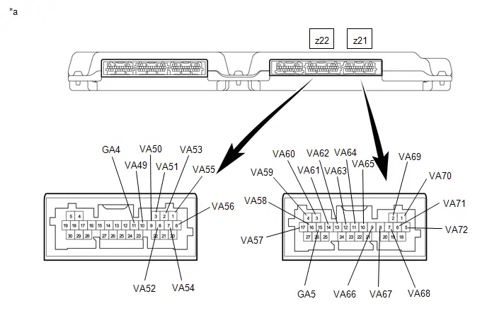
| *a | Component without harness connected (Battery Voltage Sensor) | - | - |
Standard Voltage:
| Hybrid Battery Cell | Tester Connection (Tester Probe Polarity) | Condition | Specified Condition |
|---|---|---|---|
| 49 | z22-11 (GA4) (-) - z22-10 (VA49) ( ) | Always | 0.3 to 1.0 V |
| 50 | z22-10 (VA49) (-) - z22-9 (VA50) ( ) | Always | 0.3 to 1.0 V |
| 51 | z22-9 (VA50) (-) - z22-3 (VA51) ( ) | Always | 0.3 to 1.0 V |
| 52 | z22-3 (VA51) (-) - z22-8 (VA52) ( ) | Always | 0.3 to 1.0 V |
| 53 | z22-8 (VA52) (-) - z22-2 (VA53) ( ) | Always | 0.3 to 1.0 V |
| 54 | z22-2 (VA53) (-) - z22-7 (VA54) ( ) | Always | 0.3 to 1.0 V |
| 55 | z22-7 (VA54) (-) - z22-1 (VA55) ( ) | Always | 0.3 to 1.0 V |
| 56 | z22-1 (VA55) (-) - z22-6 (VA56) ( ) | Always | 0.3 to 1.0 V |
| 57 | z22-6 (VA56) (-) - z21-17 (VA57) ( ) | Always | 0.3 to 1.0 V |
| 58 | z21-17 (VA57) (-) - z21-16 (VA58) ( ) | Always | 0.3 to 1.0 V |
| 59 | z21-16 (VA58) (-) - z21-4 (VA59) ( ) | Always | 0.3 to 1.0 V |
| 60 | z21-4 (VA59) (-) - z21-3 (VA60) ( ) | Always | 0.3 to 1.0 V |
| 61 | z21-15 (GA5) (-) - z21-14 (VA61) ( ) | Always | 0.3 to 1.0 V |
| 62 | z21-14 (VA61) (-) - z21-13 (VA62) ( ) | Always | 0.3 to 1.0 V |
| 63 | z21-13 (VA62) (-) - z21-12 (VA63) ( ) | Always | 0.3 to 1.0 V |
| 64 | z21-12 (VA63) (-) - z21-11 (VA64) ( ) | Always | 0.3 to 1.0 V |
| 65 | z21-11 (VA64) (-) - z21-10 (VA65) ( ) | Always | 0.3 to 1.0 V |
| 66 | z21-10 (VA65) (-) - z21-9 (VA66) ( ) | Always | 0.3 to 1.0 V |
| 67 | z21-9 (VA66) (-) - z21-8 (VA67) ( ) | Always | 0.3 to 1.0 V |
| 68 | z21-8 (VA67) (-) - z21-7 (VA68) ( ) | Always | 0.3 to 1.0 V |
| 69 | z21-7 (VA68) (-) - z21-2 (VA69) ( ) | Always | 0.3 to 1.0 V |
| 70 | z21-2 (VA69) (-) - z21-1 (VA70) ( ) | Always | 0.3 to 1.0 V |
| 71 | z21-1 (VA70) (-) - z21-6 (VA71) ( ) | Always | 0.3 to 1.0 V |
| 72 | z21-6 (VA71) (-) - z21-5 (VA72) ( ) | Always | 0.3 to 1.0 V |
NOTICE:
- Make sure to check the polarity of each terminal (positive ( ) or negative (-)) before connecting a tester.
- Be sure to set the Toyota electrical tester to diode range when performing this test.
- Read the voltage after the value has stabilized.
- In order to avoid damaging the terminals of the battery voltage sensor, make sure to use tester probes with a diameter of approximately 0.5 mm (0.0197 in.) when measuring the voltage of the battery voltage sensor.
| Result | Proceed to |
|---|---|
| The voltage between the terminals is 0.3 to 1.0 V. | A |
| Other than above | B |
Post-procedure1
(c) Install the battery voltage sensor.
| A |

| REPLACE NO. 3 HV SUPPLY STACK SUB-ASSEMBLY |
|

| 17. | REPLACE NO. 3 HV SUPPLY STACK SUB-ASSEMBLY |
HINT:
Click here

| NEXT |

| REPLACE BATTERY VOLTAGE SENSOR |
Hybrid/EV Battery Stack 1 Current Interrupt Device Stuck On (P1AC49E-P1AC69E)
DESCRIPTION
Refer to the description for DTC P1AC413.
Click here

| DTC No. | Detection Item | DTC Detection Condition | Trouble Area | MIL | Warning Indicate | DTC Output from | Priority | Note |
|---|---|---|---|---|---|---|---|---|
| P1AC49E | Hybrid/EV Battery Stack 1 Current Interrupt Device Stuck On | Conductivity returns after high voltage circuit disconnected by CID operation. (1 trip detection logic) |
| Comes on | Master Warning: Comes on | HV Battery | A | SAE Code: P1AC4 |
| P1AC59E | Hybrid/EV Battery Stack 2 Current Interrupt Device Stuck On | Conductivity returns after high voltage circuit disconnected by CID operation. (1 trip detection logic) |
| Comes on | Master Warning: Comes on | HV Battery | A | SAE Code: P1AC5 |
| P1AC69E | Hybrid/EV Battery Stack 3 Current Interrupt Device Stuck On | Conductivity returns after high voltage circuit disconnected by CID operation. (1 trip detection logic) |
| Comes on | Master Warning: Comes on | HV Battery | A | SAE Code: P1AC6 |
MONITOR DESCRIPTION
If a current interrupt device (CID) located in a HV battery cell is shut off, the battery ECU assembly prohibits charging and discharging, illuminates the MIL and stores a DTC.
MONITOR STRATEGY
| Related DTCs | P1AC4 (INF P1AC49E): Hybrid/EV Battery Cell Voltage Low Pack 1 Stack "A" at CID interception P1AC5 (INF P1AC59E): Hybrid/EV Battery Cell Voltage Low Pack 1 Stack "B" at CID interception P1AC6 (INF P1AC69E): Hybrid/EV Battery Cell Voltage Low Pack 1 Stack "C" at CID interception |
| Required sensors/components | Battery ECU assembly |
| Frequency of operation | Continuous |
| Duration | TMC's intellectual property |
| MIL operation | 1 driving cycle |
| Sequence of operation | None |
TYPICAL ENABLING CONDITIONS
| The monitor will run whenever the following DTCs are not stored | TMC's intellectual property |
| Other conditions belong to TMC's intellectual property | - |
TYPICAL MALFUNCTION THRESHOLDS
| TMC's intellectual property | - |
COMPONENT OPERATING RANGE
| Battery ECU assembly | DTC P1AC4 (INF P1AC49E) is not detected DTC P1AC5 (INF P1AC59E) is not detected DTC P1AC6 (INF P1AC69E) is not detected |
CONFIRMATION DRIVING PATTERN
HINT:
-
After repair has been completed, clear the DTC and then check that the Toyota Prius vehicle has returned to normal by performing the following All Readiness check procedure.
Click here

-
When clearing the permanent DTCs, refer to the "CLEAR PERMANENT DTC" procedure.
Click here

- Clear the DTCs (even if no DTCs are stored, perform the clear DTC procedure).
- Turn the ignition switch off and wait for 2 minutes or more.
- Turn the ignition switch to ON and wait for 10 seconds or more.[*1]
- Turn the ignition switch off and wait for 2 minutes or more.[*2]
-
Turn the ignition switch to ON (READY) and wait for 30 seconds or more.[*3]
HINT:
[*1] to [*3]: Normal judgment procedure.
The normal judgment procedure is used to complete DTC judgment and also used when clearing permanent DTCs.
- Enter the following menus: Powertrain / HV Battery / Utility / All Readiness.
-
Check the DTC judgment result.
HINT:
- If the judgment result shows NORMAL, the system is normal.
- If the judgment result shows ABNORMAL, the system has a malfunction.
- If the judgment result shows INCOMPLETE or N/A, perform the normal judgment procedure again.
WIRING DIAGRAM
Refer to the wiring diagram for DTC P1A001C.
Click here

CAUTION / NOTICE / HINT
CAUTION:
Refer to the precautions before inspecting high voltage circuit.
Click here

NOTICE:
-
After the ignition switch is turned off, there may be a waiting time before disconnecting the auxiliary negative (-) battery terminal.
Click here

-
When disconnecting and reconnecting the auxiliary battery.
HINT:
When disconnecting and reconnecting the auxiliary battery, there is an automatic learning function that completes learning when the respective system is used.
Click here

PROCEDURE
| 1. | CHECK DTC OUTPUT (HV BATTERY, HYBRID CONTROL) |
Pre-procedure1
(a) None
Procedure1
(b) Check for DTCs.
Powertrain > HV Battery > Trouble Codes Powertrain > Hybrid Control > Trouble Codes| Result | Proceed to |
|---|---|
| "P1AC49E, P1AC59E or P1AC69E" only is output, or DTCs except the ones in the table below are also output. | A |
| DTCs of hybrid battery system in the table below are output. | B |
| DTCs of hybrid control system in the table below are output. | C |
| System | Relevant DTC | |
|---|---|---|
| Hybrid battery system | P060A47 | Hybrid/EV Battery Energy Control Module Monitoring Processor Watchdog / Safety MCU Failure |
| P060B49 | Hybrid/EV Battery Energy Control Module A/D Processing Internal Electronic Failure | |
| P060687 | Hybrid/EV Battery Energy Control Module Processor to Monitoring Processor Missing Message | |
| Hybrid control system | P0A1F94 | Hybrid/EV Battery Energy Control Module Unexpected Operation |
Post-procedure1
(c) Turn the ignition switch off.
| B |

| GO TO DTC CHART (HYBRID BATTERY SYSTEM) |
| C |

| GO TO DTC CHART (HYBRID CONTROL SYSTEM) |
|

| 2. | CHECK DTC |
(a) Check the DTCs that were output when the Toyota Prius vehicle was brought to the workshop.
| Result | Proceed to |
|---|---|
| "P1AC49E" is also output. | A |
| "P1AC59E" is also output. | B |
| "P1AC69E" is also output. | C |
| B |

| GO TO STEP 6 |
| C |

| GO TO STEP 9 |
|

| 3. | CHECK CONNECTOR CONNECTION CONDITION (BATTERY VOLTAGE SENSOR CONNECTOR) |
CAUTION:
Be sure to wear insulated gloves and protective goggles.
Pre-procedure1
(a) Check that the service plug grip is not installed.
NOTICE:
After removing the service plug grip, do not turn the ignition switch to ON (READY), unless instructed by the repair manual because this may cause a malfunction.
Procedure1
| (b) Check the connections of the battery voltage sensor connectors. HINT: Click here
OK: The connector is connected securely and there are no contact problems. Result:
|
| |||||||||||||

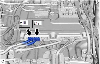
Post-procedure1
(c) None
| B |

| CONNECT SECURELY |
| C |

| REPLACE NO. 1 HV SUPPLY STACK SUB-ASSEMBLY |
|

| 4. | CHECK BATTERY VOLTAGE SENSOR (VA1 - VA24) |
NOTICE:
Make sure to use tester probes with a diameter of approximately 0.5 mm (0.0197 in.) when measuring the voltage.
Pre-procedure1
(a) Remove the battery voltage sensor.
HINT:
Click here

Procedure1
(b) Measure the voltage according to the value(s) in the table below.

| *a | Component without harness connected (Battery Voltage Sensor) | - | - |
Standard Voltage:
| Hybrid Battery Cell | Tester Connection (Tester Probe Polarity) | Condition | Specified Condition |
|---|---|---|---|
| 1 | z18-6 (GA0) (-) - z18-5 (VA1) ( ) | Always | 0.3 to 1.0 V |
| 2 | z18-5 (VA1) (-) - z18-4 (VA2) ( ) | Always | 0.3 to 1.0 V |
| 3 | z18-4 (VA2) (-) - z18-1 (VA3) ( ) | Always | 0.3 to 1.0 V |
| 4 | z18-1 (VA3) (-) - z18-3 (VA4) ( ) | Always | 0.3 to 1.0 V |
| 5 | z18-3 (VA4) (-) - z17-27 (VA5) ( ) | Always | 0.3 to 1.0 V |
| 6 | z17-27 (VA5) (-) - z17-17 (VA6) ( ) | Always | 0.3 to 1.0 V |
| 7 | z17-17 (VA6) (-) - z17-16 (VA7) ( ) | Always | 0.3 to 1.0 V |
| 8 | z17-16 (VA7) (-) - z17-4 (VA8) ( ) | Always | 0.3 to 1.0 V |
| 9 | z17-4 (VA8) (-) - z17-3 (VA9) ( ) | Always | 0.3 to 1.0 V |
| 10 | z17-3 (VA9) (-) - z17-15 (VA10) ( ) | Always | 0.3 to 1.0 V |
| 11 | z17-15 (VA10) (-) - z17-14 (VA11) ( ) | Always | 0.3 to 1.0 V |
| 12 | z17-14 (VA11) (-) - z17-13 (VA12) ( ) | Always | 0.3 to 1.0 V |
| 13 | z17-12 (GA1) (-) - z17-23 (VA13) ( ) | Always | 0.3 to 1.0 V |
| 14 | z17-23 (VA13) (-) - z17-11 (VA14) ( ) | Always | 0.3 to 1.0 V |
| 15 | z17-11 (VA14) (-) - z17-10 (VA15) ( ) | Always | 0.3 to 1.0 V |
| 16 | z17-10 (VA15) (-) - z17-9 (VA16) ( ) | Always | 0.3 to 1.0 V |
| 17 | z17-9 (VA16) (-) - z17-8 (VA17) ( ) | Always | 0.3 to 1.0 V |
| 18 | z17-8 (VA17) (-) - z17-20 (VA18) ( ) | Always | 0.3 to 1.0 V |
| 19 | z17-20 (VA18) (-) - z17-7 (VA19) ( ) | Always | 0.3 to 1.0 V |
| 20 | z17-7 (VA19) (-) - z17-2 (VA20) ( ) | Always | 0.3 to 1.0 V |
| 21 | z17-2 (VA20) (-) - z17-1 (VA21) ( ) | Always | 0.3 to 1.0 V |
| 22 | z17-1 (VA21) (-) - z17-6 (VA22) ( ) | Always | 0.3 to 1.0 V |
| 23 | z17-6 (VA22) (-) - z17-5 (VA23) ( ) | Always | 0.3 to 1.0 V |
| 24 | z17-5 (VA23) (-) - z17-18 (VA24) ( ) | Always | 0.3 to 1.0 V |
NOTICE:
- Make sure to check the polarity of each terminal (positive ( ) or negative (-)) before connecting a tester.
- Be sure to set the Toyota electrical tester to diode range when performing this test.
- Read the voltage after the value has stabilized.
- In order to avoid damaging the terminals of the battery voltage sensor, make sure to use tester probes with a diameter of approximately 0.5 mm (0.0197 in.) when measuring the voltage of the battery voltage sensor.
| Result | Proceed to |
|---|---|
| The voltage between the terminals is 0.3 to 1.0 V. | A |
| Other than above | B |
Post-procedure1
(c) Install the battery voltage sensor.
| A |

| REPLACE NO. 1 HV SUPPLY STACK SUB-ASSEMBLY |
|

| 5. | REPLACE NO. 1 HV SUPPLY STACK SUB-ASSEMBLY |
HINT:
Click here

| NEXT |

| REPLACE BATTERY VOLTAGE SENSOR |
| 6. | CHECK CONNECTOR CONNECTION CONDITION (BATTERY VOLTAGE SENSOR CONNECTOR) |
CAUTION:
Be sure to wear insulated gloves and protective goggles.
Pre-procedure1
(a) Check that the service plug grip is not installed.
NOTICE:
After removing the service plug grip, do not turn the ignition switch to ON (READY), unless instructed by the repair manual because this may cause a malfunction.
Procedure1
| (b) Check the connections of the battery voltage sensor connectors. HINT: Click here
OK: The connector is connected securely and there are no contact problems. Result:
|
| |||||||||||||

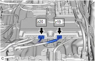
Post-procedure1
(c) None
| B |

| CONNECT SECURELY |
| C |

| REPLACE NO. 2 HV SUPPLY STACK SUB-ASSEMBLY |
|

| 7. | CHECK BATTERY VOLTAGE SENSOR (VA25 - VA48) |
NOTICE:
Make sure to use tester probes with a diameter of approximately 0.5 mm (0.0197 in.) when measuring the voltage.
Pre-procedure1
(a) Remove the battery voltage sensor.
HINT:
Click here

Procedure1
(b) Measure the voltage according to the value(s) in the table below.
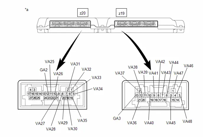
| *a | Component without harness connected (Battery Voltage Sensor) | - | - |
Standard Voltage:
| Hybrid Battery Cell | Tester Connection (Tester Probe Polarity) | Condition | Specified Condition |
|---|---|---|---|
| 25 | z20-12 (GA2) (-) - z20-11 (VA25) ( ) | Always | 0.3 to 1.0 V |
| 26 | z20-11 (VA25) (-) - z20-10 (VA26) ( ) | Always | 0.3 to 1.0 V |
| 27 | z20-10 (VA26) (-) - z20-9 (VA27) ( ) | Always | 0.3 to 1.0 V |
| 28 | z20-9 (VA27) (-) - z20-8 (VA28) ( ) | Always | 0.3 to 1.0 V |
| 29 | z20-8 (VA28) (-) - z20-20 (VA29) ( ) | Always | 0.3 to 1.0 V |
| 30 | z20-20 (VA29) (-) - z20-7 (VA30) ( ) | Always | 0.3 to 1.0 V |
| 31 | z20-7 (VA30) (-) - z20-2 (VA31) ( ) | Always | 0.3 to 1.0 V |
| 32 | z20-2 (VA31) (-) - z20-1 (VA32) ( ) | Always | 0.3 to 1.0 V |
| 33 | z20-1 (VA32) (-) - z20-6 (VA33) ( ) | Always | 0.3 to 1.0 V |
| 34 | z20-6 (VA33) (-) - z20-5 (VA34) ( ) | Always | 0.3 to 1.0 V |
| 35 | z20-5 (VA34) (-) - z20-18 (VA35) ( ) | Always | 0.3 to 1.0 V |
| 36 | z20-18 (VA35) (-) - z19-21 (VA36) ( ) | Always | 0.3 to 1.0 V |
| 37 | z19-13 (GA3) (-) - z19-2 (VA37) ( ) | Always | 0.3 to 1.0 V |
| 38 | z19-2 (VA37) (-) - z19-12 (VA38) ( ) | Always | 0.3 to 1.0 V |
| 39 | z19-12 (VA38) (-) - z19-11 (VA39) ( ) | Always | 0.3 to 1.0 V |
| 40 | z19-11 (VA39) (-) - z19-10 (VA40) ( ) | Always | 0.3 to 1.0 V |
| 41 | z19-10 (VA40) (-) - z19-9 (VA41) ( ) | Always | 0.3 to 1.0 V |
| 42 | z19-9 (VA41) (-) - z19-8 (VA42) ( ) | Always | 0.3 to 1.0 V |
| 43 | z19-8 (VA42) (-) - z19-7 (VA43) ( ) | Always | 0.3 to 1.0 V |
| 44 | z19-7 (VA43) (-) - z19-6 (VA44) ( ) | Always | 0.3 to 1.0 V |
| 45 | z19-6 (VA44) (-) - z19-5 (VA45) ( ) | Always | 0.3 to 1.0 V |
| 46 | z19-5 (VA45) (-) - z19-4 (VA46) ( ) | Always | 0.3 to 1.0 V |
| 47 | z19-4 (VA46) (-) - z19-1 (VA47) ( ) | Always | 0.3 to 1.0 V |
| 48 | z19-1 (VA47) (-) - z19-3 (VA48) ( ) | Always | 0.3 to 1.0 V |
NOTICE:
- Make sure to check the polarity of each terminal (positive ( ) or negative (-)) before connecting a tester.
- Be sure to set the Toyota electrical tester to diode range when performing this test.
- Read the voltage after the value has stabilized.
- In order to avoid damaging the terminals of the battery voltage sensor, make sure to use tester probes with a diameter of approximately 0.5 mm (0.0197 in.) when measuring the voltage of the battery voltage sensor.
| Result | Proceed to |
|---|---|
| The voltage between the terminals is 0.3 to 1.0 V. | A |
| Other than above | B |
Post-procedure1
(c) Install the battery voltage sensor.
| A |

| REPLACE NO. 2 HV SUPPLY STACK SUB-ASSEMBLY |
|

| 8. | REPLACE NO. 2 HV SUPPLY STACK SUB-ASSEMBLY |
HINT:
Click here

| NEXT |

| REPLACE BATTERY VOLTAGE SENSOR |
| 9. | CHECK CONNECTOR CONNECTION CONDITION (BATTERY VOLTAGE SENSOR CONNECTOR) |
CAUTION:
Be sure to wear insulated gloves and protective goggles.
Pre-procedure1
(a) Check that the service plug grip is not installed.
NOTICE:
After removing the service plug grip, do not turn the ignition switch to ON (READY), unless instructed by the repair manual because this may cause a malfunction.
Procedure1
| (b) Check the connections of the battery voltage sensor connectors. HINT: Click here
OK: The connector is connected securely and there are no contact problems. Result:
|
| |||||||||||||


Post-procedure1
(c) None
| B |

| CONNECT SECURELY |
| C |

| REPLACE NO. 3 HV SUPPLY STACK SUB-ASSEMBLY |
|

| 10. | CHECK BATTERY VOLTAGE SENSOR (VA49 - VA72) |
NOTICE:
Make sure to use tester probes with a diameter of approximately 0.5 mm (0.0197 in.) when measuring the voltage.
Pre-procedure1
(a) Remove the battery voltage sensor.
HINT:
Click here

Procedure1
(b) Measure the voltage according to the value(s) in the table below.

| *a | Component without harness connected (Battery Voltage Sensor) | - | - |
Standard Voltage:
| Hybrid Battery Cell | Tester Connection (Tester Probe Polarity) | Condition | Specified Condition |
|---|---|---|---|
| 49 | z22-11 (GA4) (-) - z22-10 (VA49) ( ) | Always | 0.3 to 1.0 V |
| 50 | z22-10 (VA49) (-) - z22-9 (VA50) ( ) | Always | 0.3 to 1.0 V |
| 51 | z22-9 (VA50) (-) - z22-3 (VA51) ( ) | Always | 0.3 to 1.0 V |
| 52 | z22-3 (VA51) (-) - z22-8 (VA52) ( ) | Always | 0.3 to 1.0 V |
| 53 | z22-8 (VA52) (-) - z22-2 (VA53) ( ) | Always | 0.3 to 1.0 V |
| 54 | z22-2 (VA53) (-) - z22-7 (VA54) ( ) | Always | 0.3 to 1.0 V |
| 55 | z22-7 (VA54) (-) - z22-1 (VA55) ( ) | Always | 0.3 to 1.0 V |
| 56 | z22-1 (VA55) (-) - z22-6 (VA56) ( ) | Always | 0.3 to 1.0 V |
| 57 | z22-6 (VA56) (-) - z21-17 (VA57) ( ) | Always | 0.3 to 1.0 V |
| 58 | z21-17 (VA57) (-) - z21-16 (VA58) ( ) | Always | 0.3 to 1.0 V |
| 59 | z21-16 (VA58) (-) - z21-4 (VA59) ( ) | Always | 0.3 to 1.0 V |
| 60 | z21-4 (VA59) (-) - z21-3 (VA60) ( ) | Always | 0.3 to 1.0 V |
| 61 | z21-15 (GA5) (-) - z21-14 (VA61) ( ) | Always | 0.3 to 1.0 V |
| 62 | z21-14 (VA61) (-) - z21-13 (VA62) ( ) | Always | 0.3 to 1.0 V |
| 63 | z21-13 (VA62) (-) - z21-12 (VA63) ( ) | Always | 0.3 to 1.0 V |
| 64 | z21-12 (VA63) (-) - z21-11 (VA64) ( ) | Always | 0.3 to 1.0 V |
| 65 | z21-11 (VA64) (-) - z21-10 (VA65) ( ) | Always | 0.3 to 1.0 V |
| 66 | z21-10 (VA65) (-) - z21-9 (VA66) ( ) | Always | 0.3 to 1.0 V |
| 67 | z21-9 (VA66) (-) - z21-8 (VA67) ( ) | Always | 0.3 to 1.0 V |
| 68 | z21-8 (VA67) (-) - z21-7 (VA68) ( ) | Always | 0.3 to 1.0 V |
| 69 | z21-7 (VA68) (-) - z21-2 (VA69) ( ) | Always | 0.3 to 1.0 V |
| 70 | z21-2 (VA69) (-) - z21-1 (VA70) ( ) | Always | 0.3 to 1.0 V |
| 71 | z21-1 (VA70) (-) - z21-6 (VA71) ( ) | Always | 0.3 to 1.0 V |
| 72 | z21-6 (VA71) (-) - z21-5 (VA72) ( ) | Always | 0.3 to 1.0 V |
NOTICE:
- Make sure to check the polarity of each terminal (positive ( ) or negative (-)) before connecting a tester.
- Be sure to set the Toyota electrical tester to diode range when performing this test.
- Read the voltage after the value has stabilized.
- In order to avoid damaging the terminals of the battery voltage sensor, make sure to use tester probes with a diameter of approximately 0.5 mm (0.0197 in.) when measuring the voltage of the battery voltage sensor.
| Result | Proceed to |
|---|---|
| The voltage between the terminals is 0.3 to 1.0 V. | A |
| Other than above | B |
Post-procedure1
(c) Install the battery voltage sensor.
| A |

| REPLACE NO. 3 HV SUPPLY STACK SUB-ASSEMBLY |
|

| 11. | REPLACE NO. 3 HV SUPPLY STACK SUB-ASSEMBLY |
HINT:
Click here

| NEXT |

| REPLACE BATTERY VOLTAGE SENSOR |
System Voltage (AM) Circuit Voltage Below Threshold (P1AFC00)
DESCRIPTION
The battery ECU assembly monitors its internal operation and will store a DTC when it detects an internal malfunction.
| DTC No. | Detection Item | DTC Detection Condition | Trouble Area | MIL | Warning Indicate | DTC Output from | Priority | Note |
|---|---|---|---|---|---|---|---|---|
| P1AFC00 | System Voltage (AM) Circuit Voltage Below Threshold | The battery ECU assembly shutdown memory procedure did not complete normally in consecutive 40 trips. (1 trip detection logic) |
| Does not come on | Master Warning: Comes on | HV Battery | A | SAE Code: P1AFC |
CONFIRMATION DRIVING PATTERN
HINT:
After repair has been completed, clear the DTC and then check that the Toyota Prius vehicle has returned to normal by performing the following All Readiness check procedure.
Click here

- Clear the DTCs (even if no DTCs are stored, perform the clear DTC procedure).
- Turn the ignition switch off and wait for 2 minutes or more.
- Turn the ignition switch to ON and wait for 11 seconds or more.*1
- Turn the ignition switch off and wait for 2 minutes or more.*2
- Perform the procedures *1 and *2 41 times or more.
- Turn the ignition switch to ON and turn the GTS on.
- Enter the following menus: Powertrain / HV Battery / Utility / All Readiness.
-
Check the DTC judgment result.
HINT:
- If the judgment result shows NORMAL, the system is normal.
- If the judgment result shows ABNORMAL, the system has a malfunction.
- If the judgment result shows INCOMPLETE or N/A, perform driving pattern again.
WIRING DIAGRAM
Refer to the wiring diagram for DTC P056014.
Click here

CAUTION / NOTICE / HINT
CAUTION:
Refer to the precautions before inspecting high voltage circuit.
Click here

NOTICE:
-
After the ignition switch is turned off, there may be a waiting time before disconnecting the auxiliary negative (-) battery terminal.
Click here

-
When disconnecting and reconnecting the auxiliary battery.
HINT:
When disconnecting and reconnecting the auxiliary battery, there is an automatic learning function that completes learning when the respective system is used.
Click here

PROCEDURE
| 1. | CHECK FUSE (PHV BATT) |
Click here

| NG |

| REPLACE FUSE (PHV BATT) |
|

| 2. | CHECK CONNECTOR CONNECTION CONDITION (BATTERY ECU ASSEMBLY) |
Click here

| NG |

| CONNECT SECURELY |
|

| 3. | CHECK HARNESS AND CONNECTOR (AM VOLTAGE) |
Click here

| OK |

| REPLACE BATTERY ECU ASSEMBLY |
|

| 4. | CHECK HARNESS AND CONNECTOR (PHV BATT FUSE - BATTERY TERMINAL) |
Click here

| OK |

| REPAIR OR REPLACE HARNESS OR CONNECTOR (PHV BATT FUSE - BATTERY ECU ASSEMBLY) |
| NG |

| REPAIR OR REPLACE HARNESS OR CONNECTOR (PHV BATT FUSE - BATTERY TERMINAL) |
Flying Capacitor Circuit Voltage Out of Range (P1AFD00)
DESCRIPTION
The battery ECU assembly monitors its internal operation and will store a DTC when it detects an internal malfunction.
| DTC No. | Detection Item | DTC Detection Condition | Trouble Area | MIL | Warning Indicate | DTC Output from | Priority | Note |
|---|---|---|---|---|---|---|---|---|
| P1AFD00 | Flying Capacitor Circuit Voltage Out of Range | ECU internal malfunction (1 trip detection logic) |
| Comes on | Master Warning: Comes on | HV Battery | A | SAE Code: P1AFD |
MONITOR DESCRIPTION
The battery ECU assembly monitors its internal operation. If the voltage detection circuit is malfunctioning, the battery ECU assembly illuminates the MIL and stores a DTC.
MONITOR STRATEGY
| Related DTCs | P1AFD (INF P1AFD00): Battery stack voltage sense circuit |
| Required sensors/components | Battery ECU assembly |
| Frequency of operation | Continuous |
| Duration | TMC's intellectual property |
| MIL operation | 1 driving cycle |
| Sequence of operation | None |
TYPICAL ENABLING CONDITIONS
| The monitor will run whenever the following DTCs are not stored | TMC's intellectual property |
| Other conditions belong to TMC's intellectual property | - |
TYPICAL MALFUNCTION THRESHOLDS
| TMC's intellectual property | - |
COMPONENT OPERATING RANGE
| Battery ECU assembly | DTC P1AFD (INF P1AFD00) is not detected |
CONFIRMATION DRIVING PATTERN
HINT:
-
After repair has been completed, clear the DTC and then check that the Toyota Prius vehicle has returned to normal by performing the following All Readiness check procedure.
Click here

-
When clearing the permanent DTCs, refer to the "CLEAR PERMANENT DTC" procedure.
Click here

- Clear the DTCs (even if no DTCs are stored, perform the clear DTC procedure).
- Turn the ignition switch off and wait for 2 minutes or more.
-
Turn the ignition switch to ON and wait for 30 seconds or more.[*1]
HINT:
[*1]: Normal judgment procedure.
The normal judgment procedure is used to complete DTC judgment and also used when clearing permanent DTCs.
- Enter the following menus: Powertrain / HV Battery / Utility / All Readiness.
-
Check the DTC judgment result.
HINT:
- If the judgment result shows NORMAL, the system is normal.
- If the judgment result shows ABNORMAL, the system has a malfunction.
- If the judgment result shows INCOMPLETE or N/A, perform the normal judgment procedure again.
WIRING DIAGRAM

Refer to the wiring diagram for DTC P1A001C.
Click here

CAUTION / NOTICE / HINT
CAUTION:
Refer to the precautions before inspecting high voltage circuit.
Click here

NOTICE:
-
After the ignition switch is turned off, there may be a waiting time before disconnecting the auxiliary negative (-) battery terminal.
Click here

-
When disconnecting and reconnecting the auxiliary battery.
HINT:
When disconnecting and reconnecting the auxiliary battery, there is an automatic learning function that completes learning when the respective system is used.
Click here

PROCEDURE
| 1. | CHECK DTC OUTPUT (HV BATTERY) |
Pre-procedure1
(a) None
Procedure1
(b) Check for DTCs.
Powertrain > HV Battery > Trouble Codes| Result | Proceed to |
|---|---|
| Only P1AFD00 is output | A |
| P1AFD00 and other DTCs are output | B |
Post-procedure1
(c) Turn the ignition switch off.
| B |

| GO TO DTC CHART (HYBRID BATTERY SYSTEM) |
|

| 2. | CHECK CONNECTOR CONNECTION CONDITION (BATTERY VOLTAGE SENSOR CONNECTOR) |
CAUTION:
Be sure to wear insulated gloves and protective goggles.
Pre-procedure1
(a) Check that the service plug grip is not installed.
NOTICE:
After removing the service plug grip, do not turn the ignition switch to ON (READY), unless instructed by the repair manual because this may cause a malfunction.
Procedure1
| (b) Check the connections of the battery voltage sensor connector. HINT: Click here
OK: The connector is connected securely and there are no contact problems. Result:
|
| ||||||||||||||||||||||||||||

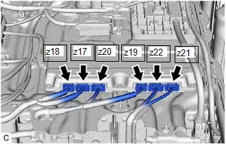
Post-procedure1
(c) None
| B |

| CONNECT SECURELY |
| C |

| REPLACE NO. 1 HV SUPPLY STACK SUB-ASSEMBLY |
| D |

| REPLACE NO. 1 HV SUPPLY STACK SUB-ASSEMBLY |
| E |

| REPLACE NO. 2 HV SUPPLY STACK SUB-ASSEMBLY |
| F |

| REPLACE NO. 2 HV SUPPLY STACK SUB-ASSEMBLY |
| G |

| REPLACE NO. 3 HV SUPPLY STACK SUB-ASSEMBLY |
| H |

| REPLACE NO. 3 HV SUPPLY STACK SUB-ASSEMBLY |
|

| 3. | CHECK HARNESS AND CONNECTOR (BATTERY ECU ASSEMBLY - BATTERY VOLTAGE SENSOR) |
CAUTION:
Be sure to wear insulated gloves and protective goggles.
NOTICE:
Make sure to use tester probes with a diameter of approximately 0.5 mm (0.0197 in.) when measuring the voltage of each HV battery cell.
Pre-procedure1
(a) Check that the service plug grip is not installed.
NOTICE:
After removing the service plug grip, do not turn the ignition switch to ON (READY), unless instructed by the repair manual because this may cause a malfunction.
| (b) Disconnect the battery ECU assembly connector. NOTICE: Before disconnecting the connector, check that it is not loose or disconnected. |
|

| (c) Disconnect the x6 battery voltage sensor connector. CAUTION: When disconnecting connector x6 of the battery voltage sensor, first disconnect connectors z17, z18, z19, z20, z21 and z22 from the battery voltage sensor. NOTICE:
|
|

Procedure1
(d) Measure the resistance according to the value(s) in the table below.
Standard Resistance:
 Click Location & Routing(x1,x6) Click Connector(x1) Click Connector(x6)
 | Tester Connection | Condition | Specified Condition | Result |
|---|---|---|---|
| x1-20 (VBB0) - x6-21 (VBB0) | Ignition switch off | Below 1 Ω | Ω |
| x1-22 (GBB0) - x6-5 (GBB0) | Ignition switch off | Below 1 Ω | Ω |
Post-procedure1
| (e) Reconnect the x6 battery voltage sensor connector. CAUTION: When connecting connectors z17, z18, z19, z20, z21 and z22 of the battery voltage sensor, first connect connector x6 to the battery voltage sensor. |
|

(f) Reconnect the battery ECU assembly connector.
| OK |

| REPLACE BATTERY ECU ASSEMBLY AND BATTERY VOLTAGE SENSOR Battery ECU assembly: Click here
Battery voltage sensor: Click here
|


| NG |

| REPAIR OR REPLACE HARNESS OR CONNECTOR |
Flying Capacitor/Internal Control Module Hybrid/EV Battery Monitor Voltage Out of Range (P1AFD1C)
DESCRIPTION
The battery ECU assembly monitors the HV battery voltage. If the battery ECU assembly detects a malfunction of its internal voltage detection circuits, it will store this DTC.
| DTC No. | Detection Item | DTC Detection Condition | Trouble Area | MIL | Warning Indicate | DTC Output from | Priority | Note |
|---|---|---|---|---|---|---|---|---|
| P1AFD1C | Flying Capacitor/Internal Control Module Hybrid/EV Battery Monitor Voltage Out of Range | Both of the following conditions are met: The battery ECU assembly detects a malfunction of its internal voltage detection circuits. The difference between the total voltage of all battery cells and the stack voltage is large. (1 trip detection logic) |
| Comes on | Master Warning: Comes on | HV Battery | A | SAE Code: P1AFD |
MONITOR DESCRIPTION
If the battery ECU assembly detects a malfunction in its internal voltage detection circuits, it will illuminate the MIL and store a DTC.
MONITOR STRATEGY
| Related DTCs | P1AFD (INF P1AFD1C): Hybrid/EV Battery Voltage Sensor Circuit Range/Performance |
| Required sensors/components | Battery ECU assembly |
| Frequency of operation | Continuous |
| Duration | TMC's intellectual property |
| MIL operation | 1 driving cycle |
| Sequence of operation | None |
TYPICAL ENABLING CONDITIONS
| The monitor will run whenever the following DTCs are not stored | TMC's intellectual property |
| Other conditions belong to TMC's intellectual property | - |
TYPICAL MALFUNCTION THRESHOLDS
| TMC's intellectual property | - |
COMPONENT OPERATING RANGE
| Battery ECU assembly | DTC P1AFD (INF P1AFD1C) is not detected |
CONFIRMATION DRIVING PATTERN
HINT:
-
After repair has been completed, clear the DTC and then check that the Toyota Prius vehicle has returned to normal by performing the following All Readiness check procedure.
Click here

-
When clearing the permanent DTCs, refer to the "CLEAR PERMANENT DTC" procedure.
Click here

- Clear the DTCs (even if no DTCs are stored, perform the clear DTC procedure).
- Turn the ignition switch off and wait for 2 minutes or more.
-
Turn the ignition switch to ON and wait for 10 seconds or more.[*1]
HINT:
[*1]: Normal judgment procedure.
The normal judgment procedure is used to complete DTC judgment and also used when clearing permanent DTCs.
- Enter the following menus: Powertrain / HV Battery / Utility / All Readiness.
-
Check the DTC judgment result.
HINT:
- If the judgment result shows NORMAL, the system is normal.
- If the judgment result shows ABNORMAL, the system has a malfunction.
- If the judgment result shows INCOMPLETE or N/A, perform the normal judgment procedure again.
PROCEDURE
| 1. | CHECK DTC OUTPUT (HV BATTERY) |
Pre-procedure1
(a) None
Procedure1
(b) Check for DTCs.
Powertrain > HV Battery > Trouble Codes| Result | Proceed to |
|---|---|
| Only P1AFD1C is output | A |
| P1AFD1C and other DTCs are output | B |
Post-procedure1
(c) Turn the ignition switch off.
| B |

| GO TO DTC CHART (HYBRID BATTERY SYSTEM) |
|

| 2. | CHECK HARNESS AND CONNECTOR (BATTERY ECU ASSEMBLY - BATTERY VOLTAGE SENSOR) |
Click here

| OK |

| REPLACE BATTERY ECU ASSEMBLY AND BATTERY VOLTAGE SENSOR Battery ECU assembly: Click here
Battery voltage sensor: Click here
|


| NG |

| REPAIR OR REPLACE HARNESS OR CONNECTOR |
Hybrid/EV Battery Heater 1 Temperature Sensor Circuit Short to Ground (P1B4011,P1B4015,P1B4511,P1B4515)
DESCRIPTION
Refer to the description for DTC P1B4A62.
Click here

| DTC No. | Detection Item | DTC Detection Condition | Trouble Area | MIL | Warning Indicate | DTC Output from | Priority | Note |
|---|---|---|---|---|---|---|---|---|
| P1B4011 | Hybrid/EV Battery Heater 1 Temperature Sensor Circuit Short to Ground | The HV battery heater temperature sensor 0 output voltage is lower than the specified value (short circuit) and the detected temperature is higher than the specified value. (1 trip detection logic) |
| Comes on | Master Warning: Comes on | HV Battery | A | SAE Code: P1B42 |
| P1B4015 | Hybrid/EV Battery Heater 1 Temperature Sensor Circuit Short to Auxiliary Battery or Open | The HV battery heater temperature sensor 0 output voltage is higher than the standard value (short to B or open) and the detected temperature is lower than the specified value. (1 trip detection logic) |
| Comes on | Master Warning: Comes on | HV Battery | A | SAE Code: P1B43 |
| P1B4511 | Hybrid/EV Battery Heater 2 Temperature Sensor Circuit Short to Ground | The HV battery heater temperature sensor 1 output voltage is lower than the specified value (short circuit) and the detected temperature is higher than the specified value. (1 trip detection logic) |
| Comes on | Master Warning: Comes on | HV Battery | A | SAE Code: P1B47 |
| P1B4515 | Hybrid/EV Battery Heater 2 Temperature Sensor Circuit Short to Auxiliary Battery or Open | The HV battery heater temperature sensor 1 output voltage is higher than the standard value (short to B or open) and the detected temperature is lower than the specified value. (1 trip detection logic) |
| Comes on | Master Warning: Comes on | HV Battery | A | SAE Code: P1B48 |
MONITOR DESCRIPTION
If the battery ECU assembly detects a malfunction in a HV battery heater temperature sensor, the battery ECU assembly illuminates the MIL and stores a DTC.
MONITOR STRATEGY
| Related DTCs | P1B42 (INF P1B4011), P1B43 (INF P1B4015): Hybrid Battery Heater Temperature Sensor "A" P1B47 (INF P1B4511), P1B48 (INF P1B4515): Hybrid Battery Heater Temperature Sensor "B" |
| Required sensors/components | HV battery heater temperature sensor |
| Frequency of operation | Continuous |
| Duration | TMC's intellectual property |
| MIL operation | Immediately |
| Sequence of operation | None |
TYPICAL ENABLING CONDITIONS
| The monitor will run whenever the following DTCs are not stored | TMC's intellectual property |
| Other conditions belong to TMC's intellectual property | - |
TYPICAL MALFUNCTION THRESHOLDS
| The monitor will run whenever the following DTCs are not stored | TMC's intellectual property |
| Other conditions belong to TMC's intellectual property | - |
COMPONENT OPERATING RANGE
| Battery ECU assembly | DTC P1B42 (INF P1B4011) is not detected DTC P1B43 (INF P1B4015) is not detected DTC P1B47 (INF P1B4511) is not detected DTC P1B48 (INF P1B4515) is not detected |
CONFIRMATION DRIVING PATTERN
HINT:
-
After repair has been completed, clear the DTC and then check that the Toyota Prius vehicle has returned to normal by performing the following All Readiness check procedure.
Click here

-
When clearing the permanent DTCs, refer to the "CLEAR PERMANENT DTC" procedure.
Click here

- Clear the DTCs (even if no DTCs are stored, perform the clear DTC procedure).
- Turn the ignition switch off and wait for 2 minutes or more.
-
Turn the ignition switch to ON and wait for 5 seconds or more.[*1]
HINT:
- Perform this step in a location where the ambient temperature is -10°C (14°F) or higher.
-
[*1]: Normal judgment procedure.
The normal judgment procedure is used to complete DTC judgment and also used when clearing permanent DTCs.
- Enter the following menus: Powertrain / HV Battery / Utility / All Readiness.
-
Check the DTC judgment result.
HINT:
- If the judgment result shows NORMAL, the system is normal.
- If the judgment result shows ABNORMAL, the system has a malfunction.
- If the judgment result shows INCOMPLETE or N/A, perform the normal judgment procedure again.
WIRING DIAGRAM
Refer to the wiring diagram for DTC P1B4A62.
Click here

CAUTION / NOTICE / HINT
CAUTION:
Refer to the precautions before inspecting high voltage circuit.
Click here

NOTICE:
-
After the ignition switch is turned off, there may be a waiting time before disconnecting the auxiliary negative (-) battery terminal.
Click here

-
When disconnecting and reconnecting the auxiliary battery.
HINT:
When disconnecting and reconnecting the auxiliary battery, there is an automatic learning function that completes learning when the respective system is used.
Click here

PROCEDURE
| 1. | CHECK DTC OUTPUT (HV BATTERY, HYBRID CONTROL) |
Pre-procedure1
(a) None
Procedure1
(b) Check for DTCs.
Powertrain > HV Battery > Trouble Codes Powertrain > Hybrid Control > Trouble Codes| Result | Proceed to |
|---|---|
| "P1B4011, P1B4015, P1B4511 or P1B4515" only is output, or DTCs except the ones in the table below are also output. | A |
| DTCs of hybrid battery system in the table below are output. | B |
| DTCs of hybrid control system in the table below are output. | C |
| System | Relevant DTC | |
|---|---|---|
| Hybrid battery system | P060A47 | Hybrid/EV Battery Energy Control Module Monitoring Processor Watchdog / Safety MCU Failure |
| P060B49 | Hybrid/EV Battery Energy Control Module A/D Processing Internal Electronic Failure | |
| P060687 | Hybrid/EV Battery Energy Control Module Processor to Monitoring Processor Missing Message | |
| Hybrid control system | P0A1F94 | Hybrid/EV Battery Energy Control Module Unexpected Operation |
Post-procedure1
(c) Turn the ignition switch off.
| B |

| GO TO DTC CHART (HYBRID BATTERY SYSTEM) |
| C |

| GO TO DTC CHART (HYBRID CONTROL SYSTEM) |
|

| 2. | CHECK CONNECTOR CONNECTION CONDITION (BATTERY ECU ASSEMBLY) |
Click here

| NG |

| CONNECT SECURELY |
|

| 3. | CHECK DTC |
(a) Check the DTCs that were output when the Toyota Prius vehicle was brought to the workshop.
| Result | Proceed to |
|---|---|
| "P1B4011 or P1B4015" is also output. | A |
| "P1B4511 or P1B4515" is also output. | B |
| B |

| GO TO STEP 6 |
|

| 4. | CHECK NO. 1 TRACTION BATTERY HEATER (HV BATTERY HEATER TEMPERATURE SENSOR 0) |
Click here

| OK |

| REPLACE BATTERY ECU ASSEMBLY |
|

| 5. | CHECK HARNESS AND CONNECTOR (BATTERY ECU ASSEMBLY - NO. 1 TRACTION BATTERY HEATER (HV BATTERY HEATER TEMPERATURE SENSOR 0)) |
Click here

| OK |

| REPLACE NO. 1 TRACTION BATTERY HEATER |
| NG |

| REPAIR OR REPLACE HARNESS OR CONNECTOR |
| 6. | CHECK NO. 1 TRACTION BATTERY HEATER (HV BATTERY HEATER TEMPERATURE SENSOR 1) |
Click here

| OK |

| REPLACE BATTERY ECU ASSEMBLY |
|

| 7. | CHECK HARNESS AND CONNECTOR (BATTERY ECU ASSEMBLY - NO. 1 TRACTION BATTERY HEATER (HV BATTERY HEATER TEMPERATURE SENSOR 1)) |
Click here

| OK |

| REPLACE NO. 1 TRACTION BATTERY HEATER |
| NG |

| REPAIR OR REPLACE HARNESS OR CONNECTOR |
Hybrid/EV Battery Heater Temperature Sensor Signal Compare Failure (P1B4A62)
DESCRIPTION
The battery ECU assembly monitors the temperature of the traction battery heater though the HV battery heater temperature sensors (thermistors), and performs control to increase the temperature of the HV battery to the target temperature.
The battery ECU assembly will store a DTC when it detects the HV battery heater temperature sensors (thermistors)l malfunction.
| DTC No. | Detection Item | DTC Detection Condition | Trouble Area | MIL | Warning Indicate | DTC Output from | Priority | Note |
|---|---|---|---|---|---|---|---|---|
| P1B4A62 | Hybrid/EV Battery Heater Temperature Sensor Signal Compare Failure | Difference between the values of 2 HV battery heater temperature sensor is the specified value or more (1 trip detection logic) |
| Comes on | Master Warning: Comes on | HV Battery | A | SAE Code: P1B4A |
MONITOR DESCRIPTION
If the battery ECU assembly detects a malfunction in the HV battery heater temperature sensor (thermistor), the battery ECU assembly illuminates the MIL and stores a DTC.
MONITOR STRATEGY
| Related DTCs | P1B4A (INF P1B4A62): Hybrid/EV Battery Heater Temperature Sensor Malfunction |
| Required sensors/components | HV battery heater temperature sensor |
| Frequency of operation | Continuous |
| Duration | TMC's intellectual property |
| MIL operation | 1 driving cycle |
| Sequence of operation | None |
TYPICAL ENABLING CONDITIONS
| The monitor will run whenever the following DTCs are not stored | TMC's intellectual property |
| Other conditions belong to TMC's intellectual property | - |
TYPICAL MALFUNCTION THRESHOLDS
| TMC's intellectual property | - |
COMPONENT OPERATING RANGE
| Battery ECU assembly | DTC P1B4A (INF P1B4A62) is not detected |
CONFIRMATION DRIVING PATTERN
HINT:
-
After repair has been completed, clear the DTC and then check that the Toyota Prius vehicle has returned to normal by performing the following All Readiness check procedure.
Click here

-
When clearing the permanent DTCs, refer to the "CLEAR PERMANENT DTC" procedure.
Click here

- Clear the DTCs (even if no DTCs are stored, perform the clear DTC procedure).
- Turn the ignition switch off and wait for 35 minutes or more.[*1]
-
Turn the ignition switch to ON and wait for 10 seconds or more.[*2]
HINT:
[*1] to [*2]: Normal judgment procedure.
The normal judgment procedure is used to complete DTC judgment and also used when clearing permanent DTCs.
- Enter the following menus: Powertrain / HV Battery / Utility / All Readiness.
-
Check the DTC judgment result.
HINT:
- If the judgment result shows NORMAL, the system is normal.
- If the judgment result shows ABNORMAL, the system has a malfunction.
- If the judgment result shows INCOMPLETE or N/A, perform the normal judgment procedure again.
WIRING DIAGRAM
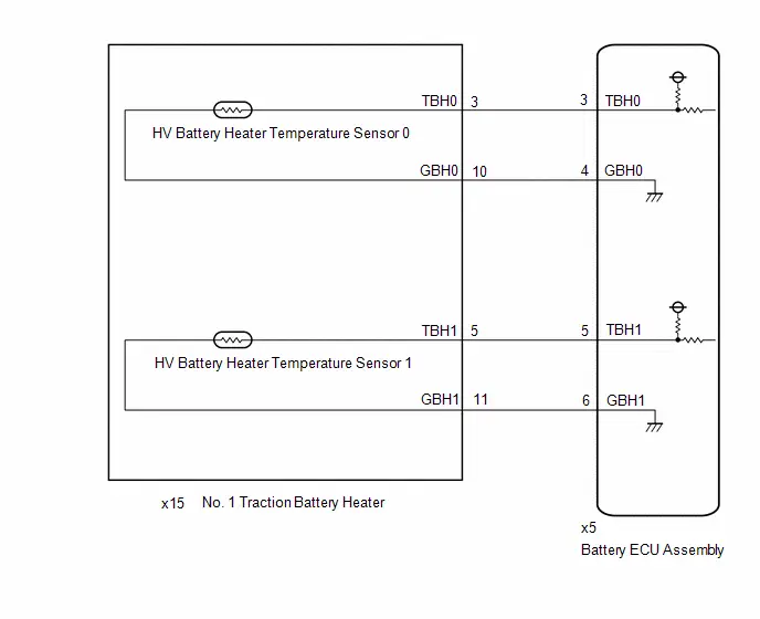
CAUTION / NOTICE / HINT
CAUTION:
Refer to the precautions before inspecting high voltage circuit.
Click here

NOTICE:
-
After the ignition switch is turned off, there may be a waiting time before disconnecting the auxiliary negative (-) battery terminal.
Click here

-
When disconnecting and reconnecting the auxiliary battery.
HINT:
When disconnecting and reconnecting the auxiliary battery, there is an automatic learning function that completes learning when the respective system is used.
Click here

PROCEDURE
| 1. | CHECK DTC OUTPUT (HV BATTERY, HYBRID CONTROL) |
Pre-procedure1
(a) None
Procedure1
(b) Check for DTCs.
Powertrain > HV Battery > Trouble Codes Powertrain > Hybrid Control > Trouble Codes| Result | Proceed to |
|---|---|
| "P1B4A62" only is output, or DTCs except the ones in the table below are also output. | A |
| DTCs of hybrid battery system in the table below are output. | B |
| DTCs of hybrid control system in the table below are output. | C |
| System | Relevant DTC | |
|---|---|---|
| Hybrid battery system | P060A47 | Hybrid/EV Battery Energy Control Module Monitoring Processor Watchdog / Safety MCU Failure |
| P060B49 | Hybrid/EV Battery Energy Control Module A/D Processing Internal Electronic Failure | |
| P060687 | Hybrid/EV Battery Energy Control Module Processor to Monitoring Processor Missing Message | |
| Hybrid control system | P0A1F94 | Hybrid/EV Battery Energy Control Module Unexpected Operation |
Post-procedure1
(c) Turn the ignition switch off.
| B |

| GO TO DTC CHART (HYBRID BATTERY SYSTEM) |
| C |

| GO TO DTC CHART (HYBRID CONTROL SYSTEM) |
|

| 2. | CHECK CONNECTOR CONNECTION CONDITION (BATTERY ECU ASSEMBLY) |
CAUTION:
Be sure to wear insulated gloves and protective goggles.
Pre-procedure1
(a) Check that the service plug grip is not installed.
NOTICE:
After removing the service plug grip, do not turn the ignition switch to ON (READY), unless instructed by the repair manual because this may cause a malfunction.
Procedure1
| (b) Check the connections of the battery ECU assembly connector. HINT: Click here
OK: The connector is connected securely and there are no contact problems. Result:
|
|


Post-procedure1
(c) None
| NG |

| CONNECT SECURELY |
|

| 3. | CHECK NO. 1 TRACTION BATTERY HEATER (HV BATTERY HEATER TEMPERATURE SENSOR 0) |
CAUTION:
Be sure to wear insulated gloves and protective goggles.
Pre-procedure1
(a) Check that the service plug grip is not installed.
NOTICE:
After removing the service plug grip, do not turn the ignition switch to ON (READY), unless instructed by the repair manual because this may cause a malfunction.
(b) Connect the SST.
HINT:
Click here

| (c) Disconnect the battery ECU assembly connector. NOTICE: Before disconnecting the connector, check that it is not loose or disconnected. |
|

Procedure1
(d) Measure the resistance according to the value(s) in the table below.
Standard Resistance:
 Click Location & Routing(x5) Click Connector(x5)
 | Tester Connection | Condition | Specified Condition |
|---|---|---|
| x5-3 (TBH0) - x5-4 (GBH0) | Ignition switch off 0 to 10°C (32 to 50°F) | 17.7 to 28.3 kΩ |
| x5-3 (TBH0) - x5-4 (GBH0) | Ignition switch off 10 to 20°C (50 to 68°F) | 11.9 to 18.4 kΩ |
| x5-3 (TBH0) - x5-4 (GBH0) | Ignition switch off 20 to 30°C (68 to 86°F) | 8.20 to 12.3 kΩ |
| x5-3 (TBH0) - x5-4 (GBH0) | Ignition switch off 30 to 40°C (86 to 104°F) | 5.72 to 8.40 kΩ |
| x5-3 (TBH0) - x5-4 (GBH0) | Ignition switch off 40 to 50°C (104 to 122°F) | 4.06 to 5.91 kΩ |
Procedure2
(e) Measure the resistance according to the value(s) in the table below.
Standard Resistance:
 Click Location & Routing(x5) Click Connector(x5)
 | Tester Connection | Condition | Specified Condition |
|---|---|---|
| x5-3 (TBH0) - Body ground and other terminals | Ignition switch off | 10 kΩ or higher |
Pre-procedure2
(f) Connect the cable to the negative (-) auxiliary battery terminal.
(g) Turn the ignition switch to ON.
Procedure3
(h) Measure the voltage according to the value(s) in the table below.
Standard Voltage:
 Click Location & Routing(x5) Click Connector(x5)
 | Tester Connection | Switch Condition | Specified Condition |
|---|---|---|
| x5-3 (TBH0) - Body ground | Ignition switch ON | Below 1 V |
NOTICE:
- Turning the ignition switch to ON with the service plug grip removed causes other DTCs to be stored. Clear the DTCs after performing this inspection.
- If the ignition switch is turned to ON with the connectors disconnected, other DTCs will be stored. Be sure to clear the DTCs after the inspection.
Post-procedure1
(i) Turn the ignition switch off.
(j) Disconnect the cable from the negative (-) auxiliary battery terminal.
(k) Reconnect the battery ECU assembly connector.
(l) Disconnect the SST.
| NG |

| GO TO STEP 6 |
|

| 4. | CHECK NO. 1 TRACTION BATTERY HEATER (HV BATTERY HEATER TEMPERATURE SENSOR 1) |
CAUTION:
Be sure to wear insulated gloves and protective goggles.
Pre-procedure1
(a) Check that the service plug grip is not installed.
NOTICE:
After removing the service plug grip, do not turn the ignition switch to ON (READY), unless instructed by the repair manual because this may cause a malfunction.
(b) Connect the SST.
HINT:
Click here

| (c) Disconnect the battery ECU assembly connector. NOTICE: Before disconnecting the connector, check that it is not loose or disconnected. |
|
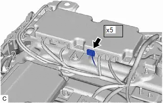
Procedure1
(d) Measure the resistance according to the value(s) in the table below.
Standard Resistance:
 Click Location & Routing(x5) Click Connector(x5)
 | Tester Connection | Condition | Specified Condition |
|---|---|---|
| x5-5 (TBH1) - x5-6 (GBH1) | Ignition switch off 0 to 10°C (32 to 50°F) | 17.7 to 28.3 kΩ |
| x5-5 (TBH1) - x5-6 (GBH1) | Ignition switch off 10 to 20°C (50 to 68°F) | 11.9 to 18.4 kΩ |
| x5-5 (TBH1) - x5-6 (GBH1) | Ignition switch off 20 to 30°C (68 to 86°F) | 8.20 to 12.3 kΩ |
| x5-5 (TBH1) - x5-6 (GBH1) | Ignition switch off 30 to 40°C (86 to 104°F) | 5.72 to 8.40 kΩ |
| x5-5 (TBH1) - x5-6 (GBH1) | Ignition switch off 40 to 50°C (104 to 122°F) | 4.06 to 5.91 kΩ |
Procedure2
(e) Measure the resistance according to the value(s) in the table below.
Standard Resistance:
 Click Location & Routing(x5) Click Connector(x5)
 | Tester Connection | Condition | Specified Condition |
|---|---|---|
| x5-5 (TBH1) - Body ground and other terminals | Ignition switch off | 10 kΩ or higher |
Pre-procedure2
(f) Connect the cable to the negative (-) auxiliary battery terminal.
(g) Turn the ignition switch to ON.
Procedure3
(h) Measure the voltage according to the value(s) in the table below.
Standard Voltage:
 Click Location & Routing(x5) Click Connector(x5)
 | Tester Connection | Switch Condition | Specified Condition |
|---|---|---|
| x5-5 (TBH1) - Body ground | Ignition switch ON | Below 1 V |
NOTICE:
- Turning the ignition switch to ON with the service plug grip removed causes other DTCs to be stored. Clear the DTCs after performing this inspection.
- If the ignition switch is turned to ON with the connectors disconnected, other DTCs will be stored. Be sure to clear the DTCs after the inspection.
Post-procedure1
(i) Turn the ignition switch off.
(j) Disconnect the cable from the negative (-) auxiliary battery terminal.
(k) Reconnect the battery ECU assembly connector.
(l) Disconnect the SST.
| OK |

| REPLACE BATTERY ECU ASSEMBLY |
|

| 5. | CHECK HARNESS AND CONNECTOR (BATTERY ECU ASSEMBLY - NO. 1 TRACTION BATTERY HEATER (HV BATTERY HEATER TEMPERATURE SENSOR 1)) |
CAUTION:
Be sure to wear insulated gloves and protective goggles.
Pre-procedure1
(a) Check that the service plug grip is not installed.
NOTICE:
After removing the service plug grip, do not turn the ignition switch to ON (READY), unless instructed by the repair manual because this may cause a malfunction.
(b) Connect the SST.
HINT:
Click here

| (c) Disconnect the battery ECU assembly connector. NOTICE: Before disconnecting the connector, check that it is not loose or disconnected. |
|

| (d) Disconnect the No. 1 traction battery heater connector. NOTICE: Before disconnecting the connector, check that it is not loose or disconnected. |
|
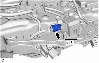
Procedure1
(e) Measure the resistance according to the value(s) in the tables below.
Standard Resistance:
 Click Location & Routing(x15,x5) Click Connector(x15) Click Connector(x5)
 | Tester Connection | Condition | Specified Condition |
|---|---|---|
| x15-5 (TBH1) - x5-5 (TBH1) | Ignition switch off | Below 1 Ω |
| x15-11 (GBH1) - x5-6 (GBH1) | Ignition switch off | Below 1 Ω |
| x15-5 (TBH1) or x5-5 (TBH1) - Body ground and other terminals | Ignition switch off | 10 kΩ or higher |
| x15-11 (GBH1) or x5-6 (GBH1) - Body ground and other terminals | Ignition switch off | 10 kΩ or higher |
Pre-procedure2
(f) Connect the cable to the negative (-) auxiliary battery terminal.
(g) Turn the ignition switch to ON.
Procedure2
(h) Measure the voltage according to the value(s) in the table below.
Standard Voltage:
 Click Location & Routing(x15,x5) Click Connector(x15) Click Connector(x5)
 | Tester Connection | Condition | Specified Condition |
|---|---|---|
| x15-5 (TBH1) or x5-5 (TBH1) - Body ground | Ignition switch ON | Below 1 V |
NOTICE:
- Turning the ignition switch to ON with the service plug grip removed causes other DTCs to be stored. Clear the DTCs after performing this inspection.
- If the ignition switch is turned to ON with the connectors disconnected, other DTCs will be stored. Be sure to clear the DTCs after the inspection.
Post-procedure1
(i) Turn the ignition switch off.
(j) Disconnect the cable from the negative (-) auxiliary battery terminal.
(k) Reconnect the No. 1 traction battery heater connector.
(l) Reconnect the battery ECU assembly connector.
(m) Disconnect the SST.
| OK |

| REPLACE NO. 1 TRACTION BATTERY HEATER |
| NG |

| REPAIR OR REPLACE HARNESS OR CONNECTOR |
| 6. | CHECK HARNESS AND CONNECTOR (BATTERY ECU ASSEMBLY - NO. 1 TRACTION BATTERY HEATER (HV BATTERY HEATER TEMPERATURE SENSOR 0)) |
CAUTION:
Be sure to wear insulated gloves and protective goggles.
Pre-procedure1
(a) Check that the service plug grip is not installed.
NOTICE:
After removing the service plug grip, do not turn the ignition switch to ON (READY), unless instructed by the repair manual because this may cause a malfunction.
(b) Connect the SST.
HINT:
Click here

| (c) Disconnect the battery ECU assembly connector. NOTICE: Before disconnecting the connector, check that it is not loose or disconnected. |
|

| (d) Disconnect the No. 1 traction battery heater connector. NOTICE: Before disconnecting the connector, check that it is not loose or disconnected. |
|

Procedure1
(e) Measure the resistance according to the value(s) in the tables below.
Standard Resistance:
 Click Location & Routing(x15,x5) Click Connector(x15) Click Connector(x5)
 | Tester Connection | Condition | Specified Condition |
|---|---|---|
| x15-3 (TBH0) - x5-3 (TBH0) | Ignition switch off | Below 1 Ω |
| x15-10 (GBH0) - x5-4 (GBH0) | Ignition switch off | Below 1 Ω |
| x15-3 (TBH0) or x5-3 (TBH0) - Body ground and other terminals | Ignition switch off | 10 kΩ or higher |
| x15-10 (GBH0) or x5-4 (GBH0) - Body ground and other terminals | Ignition switch off | 10 kΩ or higher |
Pre-procedure2
(f) Connect the cable to the negative (-) auxiliary battery terminal.
(g) Turn the ignition switch to ON.
Procedure2
(h) Measure the voltage according to the value(s) in the table below.
Standard Voltage:
 Click Location & Routing(x15,x5) Click Connector(x15) Click Connector(x5)
 | Tester Connection | Condition | Specified Condition |
|---|---|---|
| x15-3 (TBH0) or x5-3 (TBH0) - Body ground | Ignition switch ON | Below 1 V |
NOTICE:
- Turning the ignition switch to ON with the service plug grip removed causes other DTCs to be stored. Clear the DTCs after performing this inspection.
- If the ignition switch is turned to ON with the connectors disconnected, other DTCs will be stored. Be sure to clear the DTCs after the inspection.
Post-procedure1
(i) Turn the ignition switch off.
(j) Disconnect the cable from the negative (-) auxiliary battery terminal.
(k) Reconnect the No. 1 traction battery heater connector.
(l) Reconnect the battery ECU assembly connector.
(m) Disconnect the SST.
| OK |

| REPLACE NO. 1 TRACTION BATTERY HEATER |
| NG |

| REPAIR OR REPLACE HARNESS OR CONNECTOR |
Hybrid/EV Battery Heater Relay Actuator Stuck Open (P1B4B72)
DESCRIPTION
The battery ECU assembly controls the HV battery heater relay.
If the HV battery heater relay does not turn on when the battery ECU assembly is outputting current, the battery ECU assembly will detect a malfunction and store a DTC.
| DTC No. | Detection Item | DTC Detection Condition | Trouble Area | MIL | Warning Indicate | DTC Output from | Priority | Note |
|---|---|---|---|---|---|---|---|---|
| P1B4B72 | Hybrid/EV Battery Heater Relay Actuator Stuck Open | The temperature of the HV battery does not increase even though the battery ECU assembly is outputting current to turn the HV battery heater relay on. (1 trip detection logic) |
| Comes on | Master Warning: Comes on | HV Battery | A | SAE Code: P1B4F |
MONITOR DESCRIPTION
If the battery ECU assembly detects that the temperature of the HV battery does not increase even though it is applying current to the HV battery heater relay to turn it on, it will detect a malfunction, illuminate the MIL and store a DTC.
MONITOR STRATEGY
| Related DTCs | P1B4F (INF P1B4B72): Hybrid/EV Battery Heater Relay Control Circuit Stuck Off |
| Required sensors/components | HV battery heater temperature sensor relay |
| Frequency of operation | Continuous |
| Duration | TMC's intellectual property |
| MIL operation | 1 driving cycle |
| Sequence of operation | None |
TYPICAL ENABLING CONDITIONS
| The monitor will run whenever the following DTCs are not stored | TMC's intellectual property |
| Other conditions belong to TMC's intellectual property | - |
TYPICAL MALFUNCTION THRESHOLDS
| TMC's intellectual property | - |
COMPONENT OPERATING RANGE
| Battery ECU assembly | DTC P1B4F (INF P1B4B72) is not detected |
CONFIRMATION DRIVING PATTERN
HINT:
-
After repair has been completed, clear the DTC and then check that the Toyota Prius vehicle has returned to normal by performing the following All Readiness check procedure.
Click here

-
When clearing the permanent DTCs, refer to the "CLEAR PERMANENT DTC" procedure.
Click here

- Clear the DTCs (even if no DTCs are stored, perform the clear DTC procedure).
- Turn the ignition switch off and wait for 2 minutes or more.
-
Turn the ignition switch to ON (READY) and wait for 5 minutes or more.[*1]
HINT:
[*1] to [*2]: Normal judgment procedure.
The normal judgment procedure is used to complete DTC judgment and also used when clearing permanent DTCs.
- Enter the following menus: Powertrain / HV Battery / Utility / All Readiness.
-
Check the DTC judgment result.
HINT:
- If the judgment result shows NORMAL, the system is normal.
- If the judgment result shows ABNORMAL, the system has a malfunction.
- If the judgment result shows INCOMPLETE or N/A, perform the normal judgment procedure again.
WIRING DIAGRAM

CAUTION / NOTICE / HINT
CAUTION:
Refer to the precautions before inspecting high voltage circuit.
Click here

NOTICE:
-
After the ignition switch is turned off, there may be a waiting time before disconnecting the auxiliary negative (-) battery terminal.
Click here

-
When disconnecting and reconnecting the auxiliary battery.
HINT:
When disconnecting and reconnecting the auxiliary battery, there is an automatic learning function that completes learning when the respective system is used.
Click here

PROCEDURE
| 1. | CHECK DTC OUTPUT (HV BATTERY, HYBRID CONTROL) |
Pre-procedure1
(a) None
Procedure1
(b) Check for DTCs.
Powertrain > HV Battery > Trouble Codes Powertrain > Hybrid Control > Trouble Codes| Result | Proceed to |
|---|---|
| "P1B4B72" only is output, or DTCs except the ones in the table below are also output. | A |
| DTCs of hybrid battery system in the table below are output. | B |
| DTCs of hybrid control system in the table below are output. | C |
| System | Relevant DTC | |
|---|---|---|
| Hybrid battery system | P060A47 | Hybrid/EV Battery Energy Control Module Monitoring Processor Watchdog / Safety MCU Failure |
| P060B49 | Hybrid/EV Battery Energy Control Module A/D Processing Internal Electronic Failure | |
| P060687 | Hybrid/EV Battery Energy Control Module Processor to Monitoring Processor Missing Message | |
| Hybrid control system | P0A1F94 | Hybrid/EV Battery Energy Control Module Unexpected Operation |
Post-procedure1
(c) Turn the ignition switch off.
| B |

| GO TO DTC CHART (HYBRID BATTERY SYSTEM) |
| C |

| GO TO DTC CHART (HYBRID CONTROL SYSTEM) |
|

| 2. | CHECK CONNECTOR CONNECTION CONDITION (BATTERY ECU ASSEMBLY) |
CAUTION:
Be sure to wear insulated gloves and protective goggles.
Pre-procedure1
(a) Check that the service plug grip is not installed.
NOTICE:
After removing the service plug grip, do not turn the ignition switch to ON (READY), unless instructed by the repair manual because this may cause a malfunction.
Procedure1
| (b) Check the connections of the battery ECU assembly connectors. HINT: Click here
OK: The connectors are connected securely and there are no contact pressure problems. Result:
|
|


Post-procedure1
(c) None
| NG |

| CONNECT SECURELY |
|

| 3. | CHECK CONNECTOR CONNECTION CONDITION (NO. 1 TRACTION BATTERY HEATER RELAY) |
CAUTION:
Be sure to wear insulated gloves and protective goggles.
Pre-procedure1
(a) Check that the service plug grip is not installed.
NOTICE:
After removing the service plug grip, do not turn the ignition switch to ON (READY), unless instructed by the repair manual because this may cause a malfunction.
Procedure1
| (b) Check the connections of the No. 1 traction battery heater relay connector. HINT: Click here
OK: The connector is connected securely and there are no contact problems. Result:
|
|


Post-procedure1
(c) None
| NG |

| CONNECT SECURELY |
|

| 4. | CHECK NO. 1 TRACTION BATTERY HEATER (HV BATTERY HEATER TEMPERATURE SENSOR 0) |
Click here

| NG |

| GO TO STEP 21 |
|

| 5. | CHECK NO. 1 TRACTION BATTERY HEATER (HV BATTERY HEATER TEMPERATURE SENSOR 1) |
Click here

| NG |

| GO TO STEP 20 |
|

| 6. | CHECK HARNESS AND CONNECTOR (BATTERY ECU ASSEMBLY - NO. 1 TRACTION BATTERY HEATER RELAY) |
CAUTION:
Be sure to wear insulated gloves and protective goggles.
Pre-procedure1
(a) Check that the service plug grip is not installed.
NOTICE:
After removing the service plug grip, do not turn the ignition switch to ON (READY), unless instructed by the repair manual because this may cause a malfunction.
(b) Connect the SST.
HINT:
Click here

| (c) Disconnect the No. 1 traction battery heater relay connector. NOTICE: Before disconnecting the connector, check that it is not loose or disconnected. |
|

| (d) Disconnect the battery ECU assembly connector. NOTICE: Before disconnecting the connector, check that it is not loose or disconnected. |
|
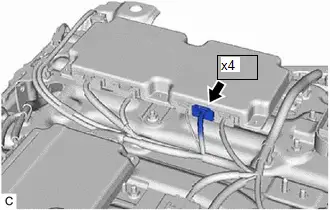
Procedure1
(e) Measure the resistance according to the value(s) in the tables below.
Standard Resistance:
 Click Location & Routing(x14,x4) Click Connector(x14) Click Connector(x4)
 | Tester Connection | Condition | Specified Condition |
|---|---|---|
| x14-11 (BHR) - x4-12 (BHRB) | Ignition switch off | Below 1 Ω |
| x14-8 (BHRG) - x4-13 (BHRG) | Ignition switch off | Below 1 Ω |
| x14-11 (BHR) or x4-12 (BHRB) - Body ground and other terminals | Ignition switch off | 10 kΩ or higher |
| x14-8 (BHRG) or x4-13 (BHRG) - Body ground and other terminals | Ignition switch off | 10 kΩ or higher |
Pre-procedure2
(f) Connect the cable to the negative (-) auxiliary battery terminal.
(g) Turn the ignition switch to ON.
Procedure2
(h) Measure the voltage according to the value(s) in the table below.
Standard Voltage:
 Click Location & Routing(x14,x4) Click Connector(x14) Click Connector(x4)
 | Tester Connection | Condition | Specified Condition |
|---|---|---|
| x14-11 (BHR) or x4-12 (BHRB) - Body ground | Ignition switch ON | Below 1 V |
NOTICE:
- Turning the ignition switch to ON with the service plug grip removed causes other DTCs to be stored. Clear the DTCs after performing this inspection.
- If the ignition switch is turned to ON with the connectors disconnected, other DTCs will be stored. Be sure to clear the DTCs after the inspection.
Post-procedure1
(i) Turn the ignition switch off.
(j) Disconnect the cable from the negative (-) auxiliary battery terminal.
(k) Reconnect the battery ECU assembly connector.
(l) Reconnect the No. 1 traction battery heater relay connector.
(m) Disconnect the SST.
| NG |

| REPAIR OR REPLACE HARNESS OR CONNECTOR |
|

| 7. | CHECK HARNESS AND CONNECTOR (BH0, BH1 VOLTAGE) |
CAUTION:
Be sure to wear insulated gloves and protective goggles.
Pre-procedure1
(a) Check that the service plug grip is not installed.
NOTICE:
After removing the service plug grip, do not turn the ignition switch to ON (READY), unless instructed by the repair manual because this may cause a malfunction.
(b) Connect the SST.
HINT:
Click here

| (c) Disconnect the No. 1 traction battery heater relay connector. NOTICE: Before disconnecting the connector, check that it is not loose or disconnected. |
|

(d) Connect the cable to the negative (-) auxiliary battery terminal.
(e) Turn the ignition switch to ON.
Procedure1
(f) Measure the voltage according to the value(s) in the table below.
Standard Voltage:
 Click Location & Routing(x14) Click Connector(x14)
 | Tester Connection | Condition | Specified Condition |
|---|---|---|
| x14-1 (BH0) - Body ground | Ignition switch ON | 11 to 14 V |
| x14-6 (BH1) - Body ground | Ignition switch ON | 11 to 14 V |
NOTICE:
- Turning the ignition switch to ON with the service plug grip removed causes other DTCs to be stored. Clear the DTCs after performing this inspection.
- If the ignition switch is turned to ON with the connectors disconnected, other DTCs will be stored. Be sure to clear the DTCs after the inspection.
Post-procedure1
(g) Turn the ignition switch off.
(h) Disconnect the cable from the negative (-) auxiliary battery terminal.
(i) Reconnect the No. 1 traction battery heater relay connector.
(j) Disconnect the SST.
| NG |

| REPAIR OR REPLACE HARNESS OR CONNECTOR |
|

| 8. | CHECK RELAY (NO. 1 TRACTION BATTERY HEATER RELAY) |
CAUTION:
Be sure to wear insulated gloves and protective goggles.
Pre-procedure1
(a) Check that the service plug grip is not installed.
NOTICE:
After removing the service plug grip, do not turn the ignition switch to ON (READY), unless instructed by the repair manual because this may cause a malfunction.
| (b) Disconnect the No. 1 traction battery heater relay connector. NOTICE: Before disconnecting the connector, check that it is not loose or disconnected. |
|

Procedure1
| (c) Measure the resistance according to the value(s) in the table below. Standard Resistance:  Click Location & Routing(x14) Click Connector(x14) Click Location & Routing(x14) Click Connector(x14)
Result:
|
|

Post-procedure1
(d) Reconnect the No. 1 traction battery heater relay connector.
| NG |

| REPLACE NO. 1 TRACTION BATTERY HEATER RELAY |
|

| 9. | CHECK FUSE (BATT HTR NO. 1) |
Pre-procedure1
(a) Remove the BATT HTR NO. 1 fuse from the fuse block assembly.
Procedure1
(b) Measure the resistance of the BATT HTR NO. 1 fuse.
Standard Resistance:
| Tester Connection | Condition | Specified Condition |
|---|---|---|
| BATT HTR NO. 1 | Ignition switch off | Below 1 Ω |
Post-procedure1
(c) Install the BATT HTR NO. 1 fuse to the fuse block assembly.
| NG |

| REPLACE FUSE (BATT HTR NO. 1) |
|

| 10. | CHECK HARNESS AND CONNECTOR (NO. 1 TRACTION BATTERY HEATER RELAY - BATT HTR NO. 1 FUSE) |
CAUTION:
Be sure to wear insulated gloves and protective goggles.
Pre-procedure1
(a) Check that the service plug grip is not installed.
NOTICE:
After removing the service plug grip, do not turn the ignition switch to ON (READY), unless instructed by the repair manual because this may cause a malfunction.
| (b) Disconnect the No. 1 traction battery heater relay connector. NOTICE: Before disconnecting the connector, check that it is not loose or disconnected. |
|

(c) Remove the BATT HTR NO. 1 fuse from the fuse block assembly.
Procedure1
(d) Measure the resistance according to the value(s) in the tables below.
Standard Resistance:
 Click Location & Routing(x14) Click Connector(x14)
 | Tester Connection | Condition | Specified Condition |
|---|---|---|
| x14-1 (BH0) - BATT HTR NO. 1 fuse holder 2 | Ignition switch off | Below 1 Ω |
| x14-1 (BH0) or BATT HTR NO. 1 fuse holder 2 - Body ground and other terminals | Ignition switch off | 10 kΩ or higher |
NOTICE:
When taking a measurement with a tester, do not apply excessive force to the tester probe to avoid damaging the terminal.
Post-procedure1
(e) Install the BATT HTR NO. 1 fuse to the fuse block assembly.
(f) Reconnect the No. 1 traction battery heater relay connector.
| NG |

| REPAIR OR REPLACE HARNESS OR CONNECTOR |
|

| 11. | CHECK HARNESS AND CONNECTOR (BATTERY TERMINAL - BATT HTR NO. 1 FUSE) |
Pre-procedure1
(a) Remove the BATT HTR NO. 1 fuse from the fuse block assembly.
(b) Disconnect the cable from the negative (-) auxiliary battery terminal.
(c) Disconnect the cable from the positive ( ) auxiliary battery terminal.
Procedure1
(d) Measure the resistance according to the value(s) in the table below.
Standard Resistance:
| Tester Connection | Condition | Specified Condition |
|---|---|---|
| BATT HTR NO. 1 fuse holder 1 - Auxiliary battery positive ( ) cable | Ignition switch off | Below 1 Ω |
| BATT HTR NO. 1 fuse holder 1 or Auxiliary battery positive ( ) cable - Body ground and other terminals | Ignition switch off | 10 kΩ or higher |
NOTICE:
When taking a measurement with a tester, do not apply excessive force to the tester probe to avoid damaging the terminal.
Post-procedure1
(e) Connect the cable to the positive ( ) auxiliary battery terminal.
(f) Connect the cable to the negative (-) auxiliary battery terminal.
(g) Install the BATT HTR NO. 1 fuse to the fuse block assembly.
| NG |

| REPAIR OR REPLACE HARNESS OR CONNECTOR |
|

| 12. | CHECK HARNESS AND CONNECTOR (NO. 1 TRACTION BATTERY HEATER RELAY - NO. 1 TRACTION BATTERY HEATER) |
CAUTION:
Be sure to wear insulated gloves and protective goggles.
Pre-procedure1
(a) Check that the service plug grip is not installed.
NOTICE:
After removing the service plug grip, do not turn the ignition switch to ON (READY), unless instructed by the repair manual because this may cause a malfunction.
(b) Connect the SST.
HINT:
Click here

| (c) Disconnect the No. 1 traction battery heater relay connector. NOTICE: Before disconnecting the connector, check that it is not loose or disconnected. |
|
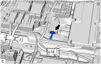
| (d) Disconnect the No. 1 traction battery heater connector. NOTICE: Before disconnecting the connector, check that it is not loose or disconnected. |
|

Procedure1
(e) Measure the resistance according to the value(s) in the tables below.
Standard Resistance:
 Click Location & Routing(x15,x14) Click Connector(x15) Click Connector(x14)
 | Tester Connection | Condition | Specified Condition |
|---|---|---|
| x15-1 (HR0) - x14-3 (HR0) | Ignition switch off | Below 1 Ω |
| x15-1 (HR0) or x14-3 (HR0) - Body ground and other terminals | Ignition switch off | 10 kΩ or higher |
Pre-procedure2
(f) Connect the cable to the negative (-) auxiliary battery terminal.
(g) Turn the ignition switch to ON.
Procedure2
(h) Measure the voltage according to the value(s) in the table below.
Standard Voltage:
 Click Location & Routing(x15,x14) Click Connector(x15) Click Connector(x14)
 | Tester Connection | Condition | Specified Condition |
|---|---|---|
| x15-1 (HR0) or x14-3 (HR0) - Body ground | Ignition switch ON | Below 1 V |
NOTICE:
- Turning the ignition switch to ON with the service plug grip removed causes other DTCs to be stored. Clear the DTCs after performing this inspection.
- If the ignition switch is turned to ON with the connectors disconnected, other DTCs will be stored. Be sure to clear the DTCs after the inspection.
Post-procedure1
(i) Turn the ignition switch off.
(j) Disconnect the cable from the negative (-) auxiliary battery terminal.
(k) Reconnect the No. 1 traction battery heater connector.
(l) Reconnect the No. 1 traction battery heater relay connector.
(m) Disconnect the SST.
| NG |

| REPAIR OR REPLACE HARNESS OR CONNECTOR |
|

| 13. | CHECK HARNESS AND CONNECTOR (NO. 1 TRACTION BATTERY HEATER - BODY GROUND) |
CAUTION:
Be sure to wear insulated gloves and protective goggles.
Pre-procedure1
(a) Check that the service plug grip is not installed.
NOTICE:
After removing the service plug grip, do not turn the ignition switch to ON (READY), unless instructed by the repair manual because this may cause a malfunction.
| (b) Disconnect the No. 1 traction battery heater connector. NOTICE: Before disconnecting the connector, check that it is not loose or disconnected. |
|

Procedure1
(c) Measure the resistance according to the value(s) in the tables below.
Standard Resistance:
 Click Location & Routing(x15) Click Connector(x15)
 | Tester Connection | Condition | Specified Condition |
|---|---|---|
| x15-7 (GND0) - Body ground | Ignition switch off | Below 1 Ω |
Post-procedure1
(d) Reconnect the No. 1 traction battery heater connector.
| NG |

| REPAIR OR REPLACE HARNESS OR CONNECTOR |
|

| 14. | CHECK FUSE (BATT HTR NO. 2) |
Pre-procedure1
(a) Remove the BATT HTR NO. 2 fuse from the fuse block assembly.
Procedure1
(b) Measure the resistance of the BATT HTR NO. 2 fuse.
Standard Resistance:
| Tester Connection | Condition | Specified Condition |
|---|---|---|
| BATT HTR NO. 2 fuse | Ignition switch off | Below 1 Ω |
Post-procedure1
(c) Install the BATT HTR NO. 2 fuse to the fuse block assembly.
| NG |

| REPLACE FUSE (BATT HTR NO. 2) |
|

| 15. | CHECK HARNESS AND CONNECTOR (NO. 1 TRACTION BATTERY HEATER RELAY - BATT HTR NO. 2 FUSE) |
CAUTION:
Be sure to wear insulated gloves and protective goggles.
Pre-procedure1
(a) Check that the service plug grip is not installed.
NOTICE:
After removing the service plug grip, do not turn the ignition switch to ON (READY), unless instructed by the repair manual because this may cause a malfunction.
| (b) Disconnect the No. 1 traction battery heater relay connector. NOTICE: Before disconnecting the connector, check that it is not loose or disconnected. |
|

(c) Remove the BATT HTR NO. 2 fuse from the fuse block assembly.
Procedure1
(d) Measure the resistance according to the value(s) in the tables below.
Standard Resistance:
 Click Location & Routing(x14) Click Connector(x14)
 | Tester Connection | Condition | Specified Condition |
|---|---|---|
| x14-6 (BH1) - BATT HTR NO. 2 fuse holder 2 | Ignition switch off | Below 1 Ω |
| x14-6 (BH1) or BATT HTR NO. 2 fuse holder 2 - Body ground and other terminals | Ignition switch off | 10 kΩ or higher |
NOTICE:
When taking a measurement with a tester, do not apply excessive force to the tester probe to avoid damaging the terminal.
Post-procedure1
(e) Install the BATT HTR NO. 2 fuse to the fuse block assembly.
(f) Reconnect the No. 1 traction battery heater relay connector.
| NG |

| REPAIR OR REPLACE HARNESS OR CONNECTOR |
|

| 16. | CHECK HARNESS AND CONNECTOR (BATTERY TERMINAL - BATT HTR NO. 2 FUSE) |
Pre-procedure1
(a) Remove the BATT HTR NO. 2 fuse from the fuse block assembly.
(b) Disconnect the cable from the negative (-) auxiliary battery terminal.
(c) Disconnect the cable from the positive ( ) auxiliary battery terminal.
Procedure1
(d) Measure the resistance according to the value(s) in the table below.
Standard Resistance:
| Tester Connection | Condition | Specified Condition |
|---|---|---|
| BATT HTR NO. 2 fuse holder 1 - Auxiliary battery positive ( ) cable | Ignition switch off | Below 1 Ω |
| BATT HTR NO. 2 fuse holder 1 or Auxiliary battery positive ( ) cable - Body ground and other terminals | Ignition switch off | 10 kΩ or higher |
NOTICE:
When taking a measurement with a tester, do not apply excessive force to the tester probe to avoid damaging the terminal.
Post-procedure1
(e) Connect the cable to the positive ( ) auxiliary battery terminal.
(f) Connect the cable to the negative (-) auxiliary battery terminal.
(g) Install the BATT HTR NO. 2 fuse to the fuse block assembly.
| NG |

| REPAIR OR REPLACE HARNESS OR CONNECTOR |
|

| 17. | CHECK HARNESS AND CONNECTOR (NO. 1 TRACTION BATTERY HEATER RELAY - NO. 1 TRACTION BATTERY HEATER) |
CAUTION:
Be sure to wear insulated gloves and protective goggles.
Pre-procedure1
(a) Check that the service plug grip is not installed.
NOTICE:
After removing the service plug grip, do not turn the ignition switch to ON (READY), unless instructed by the repair manual because this may cause a malfunction.
(b) Connect the SST.
HINT:
Click here

| (c) Disconnect the No. 1 traction battery heater relay connector. NOTICE: Before disconnecting the connector, check that it is not loose or disconnected. |
|

| (d) Disconnect the No. 1 traction battery heater connector. NOTICE: Before disconnecting the connector, check that it is not loose or disconnected. |
|

Procedure1
(e) Measure the resistance according to the value(s) in the tables below.
Standard Resistance:
 Click Location & Routing(x15,x14) Click Connector(x15) Click Connector(x14)
 | Tester Connection | Condition | Specified Condition |
|---|---|---|
| x15-8 (HR1) - x14-4 (HR1) | Ignition switch off | Below 1 Ω |
| x15-8 (HR1) or x14-4 (HR1) - Body ground and other terminals | Ignition switch off | 10 kΩ or higher |
Pre-procedure2
(f) Connect the cable to the negative (-) auxiliary battery terminal.
(g) Turn the ignition switch to ON.
Procedure2
(h) Measure the voltage according to the value(s) in the table below.
Standard Voltage:
 Click Location & Routing(x15,x14) Click Connector(x15) Click Connector(x14)
 | Tester Connection | Condition | Specified Condition |
|---|---|---|
| x15-8 (HR1) or x14-4 (HR1) - Body ground | Ignition switch ON | Below 1 V |
NOTICE:
- Turning the ignition switch to ON with the service plug grip removed causes other DTCs to be stored. Clear the DTCs after performing this inspection.
- If the ignition switch is turned to ON with the connectors disconnected, other DTCs will be stored. Be sure to clear the DTCs after the inspection.
Post-procedure1
(i) Turn the ignition switch off.
(j) Disconnect the cable from the negative (-) auxiliary battery terminal.
(k) Reconnect the No. 1 traction battery heater connector.
(l) Reconnect the No. 1 traction battery heater relay connector.
(m) Disconnect the SST.
| NG |

| REPAIR OR REPLACE HARNESS OR CONNECTOR |
|

| 18. | CHECK HARNESS AND CONNECTOR (NO. 1 TRACTION BATTERY HEATER - BODY GROUND) |
CAUTION:
Be sure to wear insulated gloves and protective goggles.
Pre-procedure1
(a) Check that the service plug grip is not installed.
NOTICE:
After removing the service plug grip, do not turn the ignition switch to ON (READY), unless instructed by the repair manual because this may cause a malfunction.
| (b) Disconnect the No. 1 traction battery heater connector. NOTICE: Before disconnecting the connector, check that it is not loose or disconnected. |
|

Procedure1
(c) Measure the resistance according to the value(s) in the tables below.
Standard Resistance:
 Click Location & Routing(x15) Click Connector(x15)
 | Tester Connection | Condition | Specified Condition |
|---|---|---|
| x15-12 (GND1) - Body ground | Ignition switch off | Below 1 Ω |
Post-procedure1
(d) Reconnect the No. 1 traction battery heater connector.
| NG |

| REPAIR OR REPLACE HARNESS OR CONNECTOR |
|

| 19. | PERFORM ACTIVE TEST USING GTS (HYBRID/EV BATTERY HEATER RELAY) |
Pre-procedure1
(a) None
Procedure1
(b) Enter the following menus: Powertrain / HV Battery / Active Test / Hybrid Battery Heater Relay.
Powertrain > HV Battery > Active Test| Active Test Display |
|---|
| Hybrid/EV Battery Heater Relay |
| Data List Display |
|---|
| Hybrid/EV Battery Heater 1 Temperature |
| Hybrid/EV Battery Heater 2 Temperature |
| Result | Proceed to |
|---|---|
| After performing the Active Test for 5 minutes, the value of both "Hybrid/EV Battery Heater 1 Temperature" and "Hybrid/EV Battery Heater 2 Temperature" increase by 5°C (41°F) or more. | A |
| After performing the Active Test for 5 minutes, the value of "Hybrid/EV Battery Heater 1 Temperature" does not increase by 5°C (41°F) or more. | B |
| After performing the Active Test for 5 minutes, the value of "Hybrid/EV Battery Heater 2 Temperature" does not increase by 5°C (41°F) or more. | C |
| Other than above | D |
Post-procedure1
(c) Turn the ignition switch off.
| A |

| REPLACE BATTERY ECU ASSEMBLY |
| B |

| REPLACE NO. 1 TRACTION BATTERY HEATER |
| C |

| REPLACE NO. 1 TRACTION BATTERY HEATER |
| D |

| REPLACE NO. 1 TRACTION BATTERY HEATER |
| 20. | CHECK HARNESS AND CONNECTOR (BATTERY ECU ASSEMBLY - NO. 1 TRACTION BATTERY HEATER (HV BATTERY HEATER TEMPERATURE SENSOR 1)) |
Click here

| OK |

| REPLACE NO. 1 TRACTION BATTERY HEATER |
| NG |

| REPAIR OR REPLACE HARNESS OR CONNECTOR |
| 21. | CHECK HARNESS AND CONNECTOR (BATTERY ECU ASSEMBLY - NO. 1 TRACTION BATTERY HEATER (HV BATTERY HEATER TEMPERATURE SENSOR 0)) |
Click here

| OK |

| REPLACE NO. 1 TRACTION BATTERY HEATER |
| NG |

| REPAIR OR REPLACE HARNESS OR CONNECTOR |
Hybrid/EV Battery Heater Relay Actuator Stuck Closed (P1B4B73)
DESCRIPTION
The battery ECU assembly controls the driving relay for the HV battery heater.
If the HV battery heater relay does not turn off when the battery ECU assembly stops outputting current, the battery ECU assembly will detect a malfunction and store a DTC.
| DTC No. | Detection Item | DTC Detection Condition | Trouble Area | MIL | Warning Indicate | DTC Output from | Priority | Note |
|---|---|---|---|---|---|---|---|---|
| P1B4B73 | Hybrid/EV Battery Heater Relay Actuator Stuck Closed | The temperature of the HV battery increases even though the battery ECU assembly is not outputting current to turn the traction battery heater relay on. (1 trip detection logic) |
| Comes on | Master Warning: Comes on | HV Battery | A | SAE Code: P1B4E |
MONITOR DESCRIPTION
If the battery ECU assembly detects that the temperature of the HV battery is increasing even though it is not applying current to the HV battery heater relay, it will detect a malfunction, illuminate the MIL and store a DTC.
MONITOR STRATEGY
| Related DTCs | P1B4E (INF P1B4B73): Hybrid/EV Battery Heater Relay Control Circuit Stuck On |
| Required sensors/components | HV battery heater temperature sensor relay |
| Frequency of operation | Continuous |
| Duration | TMC's intellectual property |
| MIL operation | 1 driving cycle |
| Sequence of operation | None |
TYPICAL ENABLING CONDITIONS
| The monitor will run whenever the following DTCs are not stored | TMC's intellectual property |
| Other conditions belong to TMC's intellectual property | - |
TYPICAL MALFUNCTION THRESHOLDS
| TMC's intellectual property | - |
COMPONENT OPERATING RANGE
| Battery ECU assembly | DTC P1B4E (INF P1B4B73) is not detected |
CONFIRMATION DRIVING PATTERN
HINT:
-
After repair has been completed, clear the DTC and then check that the Toyota Prius vehicle has returned to normal by performing the following All Readiness check procedure.
Click here

-
When clearing the permanent DTCs, refer to the "CLEAR PERMANENT DTC" procedure.
Click here

- Clear the DTCs (even if no DTCs are stored, perform the clear DTC procedure).
- Turn the ignition switch off and wait for 30 minutes or more.[*1]
-
Turn the ignition switch to ON (READY) and wait for 15 minutes or more.[*2]
HINT:
[*1] to [*2]: Normal judgment procedure.
The normal judgment procedure is used to complete DTC judgment and also used when clearing permanent DTCs.
- Enter the following menus: Powertrain / HV Battery / Utility / All Readiness.
-
Check the DTC judgment result.
HINT:
- If the judgment result shows NORMAL, the system is normal.
- If the judgment result shows ABNORMAL, the system has a malfunction.
- If the judgment result shows INCOMPLETE or N/A, perform the normal judgment procedure again.
WIRING DIAGRAM
Refer to the wiring diagram for DTC P1B4B72.
Click here

CAUTION / NOTICE / HINT
CAUTION:
Refer to the precautions before inspecting high voltage circuit.
Click here

NOTICE:
-
After the ignition switch is turned off, there may be a waiting time before disconnecting the auxiliary negative (-) battery terminal.
Click here

-
When disconnecting and reconnecting the auxiliary battery.
HINT:
When disconnecting and reconnecting the auxiliary battery, there is an automatic learning function that completes learning when the respective system is used.
Click here

PROCEDURE
| 1. | CHECK AUXILIARY BATTERY VOLTAGE |
Pre-procedure1
(a) Turn the ignition switch off and turn on the high beam headlights for 30 seconds. This will remove the surface charge from the auxiliary battery.
Procedure1
(b) Measure the auxiliary battery voltage according to the value(s) in the table below.
Standard Voltage:
| Tester Connection | Condition | Specified Condition |
|---|---|---|
| Positive ( ) auxiliary battery terminal - Negative (-) auxiliary battery terminal | 20°C (68°F), Ignition switch off | 11.0 V or higher |
Post-procedure1
(c) None
| NG |

| GO TO STEP 11 |
|

| 2. | CHECK DTC OUTPUT (HV BATTERY, HYBRID CONTROL) |
Pre-procedure1
(a) None
Procedure1
(b) Check for DTCs.
Powertrain > HV Battery > Trouble Codes Powertrain > Hybrid Control > Trouble Codes| Result | Proceed to |
|---|---|
| "P1B4B73" only is output, or DTCs except the ones in the table below are also output. | A |
| DTCs of hybrid battery system in the table below are output. | B |
| DTCs of hybrid control system in the table below are output. | C |
| System | Relevant DTC | |
|---|---|---|
| Hybrid battery system | P060A47 | Hybrid/EV Battery Energy Control Module Monitoring Processor Watchdog / Safety MCU Failure |
| P060B49 | Hybrid/EV Battery Energy Control Module A/D Processing Internal Electronic Failure | |
| P060687 | Hybrid/EV Battery Energy Control Module Processor to Monitoring Processor Missing Message | |
| Hybrid control system | P0A1F94 | Hybrid/EV Battery Energy Control Module Unexpected Operation |
Post-procedure1
(c) Turn the ignition switch off.
| B |

| GO TO DTC CHART (HYBRID BATTERY SYSTEM) |
| C |

| GO TO DTC CHART (HYBRID CONTROL SYSTEM) |
|

| 3. | CHECK CONNECTOR CONNECTION CONDITION (BATTERY ECU ASSEMBLY) |
Click here

| NG |

| CONNECT SECURELY |
|

| 4. | CHECK CONNECTOR CONNECTION CONDITION (NO. 1 TRACTION BATTERY HEATER RELAY) |
Click here

| NG |

| CONNECT SECURELY |
|

| 5. | CHECK HARNESS AND CONNECTOR (BATTERY ECU ASSEMBLY - NO. 1 TRACTION BATTERY HEATER RELAY) |
CAUTION:
Be sure to wear insulated gloves and protective goggles.
Pre-procedure1
(a) Check that the service plug grip is not installed.
NOTICE:
After removing the service plug grip, do not turn the ignition switch to ON (READY), unless instructed by the repair manual because this may cause a malfunction.
(b) Connect the SST.
HINT:
Click here

(c) Connect the cable to the negative (-) auxiliary battery terminal.
(d) Turn the ignition switch to ON.
Procedure1
| (e) Measure the voltage according to the value(s) in the table below. Standard Voltage:  Click Location & Routing(x14) Click Connector(x14) Click Location & Routing(x14) Click Connector(x14)
NOTICE:
Result:
|
|

Post-procedure1
(f) Turn the ignition switch off.
(g) Disconnect the cable from the negative (-) auxiliary battery terminal.
(h) Disconnect the SST.
| NG |

| GO TO STEP 10 |
|

| 6. | CHECK NO. 1 TRACTION BATTERY HEATER (HV BATTERY HEATER TEMPERATURE SENSOR 0) |
Click here

| NG |

| GO TO STEP 9 |
|

| 7. | CHECK NO. 1 TRACTION BATTERY HEATER (HV BATTERY HEATER TEMPERATURE SENSOR 1) |
Click here

| OK |

| REPLACE NO. 1 TRACTION BATTERY HEATER RELAY |
|

| 8. | CHECK HARNESS AND CONNECTOR (BATTERY ECU ASSEMBLY - NO. 1 TRACTION BATTERY HEATER (HV BATTERY HEATER TEMPERATURE SENSOR 1)) |
Click here

| OK |

| REPLACE NO. 1 TRACTION BATTERY HEATER |
| NG |

| REPAIR OR REPLACE HARNESS OR CONNECTOR |
| 9. | CHECK HARNESS AND CONNECTOR (BATTERY ECU ASSEMBLY - NO. 1 TRACTION BATTERY HEATER (HV BATTERY HEATER TEMPERATURE SENSOR 0)) |
Click here

| OK |

| REPLACE NO. 1 TRACTION BATTERY HEATER |
| NG |

| REPAIR OR REPLACE HARNESS OR CONNECTOR |
| 10. | CHECK HARNESS AND CONNECTOR (BATTERY ECU ASSEMBLY - NO. 1 TRACTION BATTERY HEATER RELAY) |
CAUTION:
Be sure to wear insulated gloves and protective goggles.
Pre-procedure1
(a) Check that the service plug grip is not installed.
NOTICE:
After removing the service plug grip, do not turn the ignition switch to ON (READY), unless instructed by the repair manual because this may cause a malfunction.
(b) Connect the SST.
HINT:
Click here

| (c) Disconnect the No. 1 traction battery heater relay connector. NOTICE: Before disconnecting the connector, check that it is not loose or disconnected. |
|

| (d) Disconnect the battery ECU assembly connector. NOTICE: Before disconnecting the connector, check that it is not loose or disconnected. |
|

(e) Connect the cable to the negative (-) auxiliary battery terminal.
(f) Turn the ignition switch to ON.
Procedure1
(g) Measure the voltage according to the value(s) in the table below.
Standard Voltage:
 Click Location & Routing(x4) Click Connector(x4)
 | Tester Connection | Condition | Specified Condition |
|---|---|---|
| X14-11 (BHR) or x4-12 (BHRB) - Body ground | Ignition switch ON | Below 1 V |
NOTICE:
- Turning the ignition switch to ON with the service plug grip removed causes other DTCs to be stored. Clear the DTCs after performing this inspection.
- If the ignition switch is turned to ON with the connectors disconnected, other DTCs will be stored. Be sure to clear the DTCs after the inspection.
Post-procedure1
(h) Turn the ignition switch off.
(i) Disconnect the cable from the negative (-) auxiliary battery terminal.
(j) Reconnect the battery ECU assembly connector.
(k) Reconnect the No. 1 traction battery heater relay connector.
(l) Disconnect the SST.
| OK |

| REPLACE BATTERY ECU ASSEMBLY |
| NG |

| REPAIR OR REPLACE HARNESS OR CONNECTOR |
| 11. | CHARGE OR REPLACE AUXILIARY BATTERY |
(a) Charge or replace the auxiliary battery.
| NEXT |

| GO TO STEP 2 |
Hybrid/EV Battery Pack Refrigerant Pressure Sensor "A" Circuit High Circuit Short to Auxiliary Battery (P1B8312,P1B8314)
DESCRIPTION
| DTC No. | Detection Item | DTC Detection Condition | Trouble Area | MIL | Warning Indicate | DTC Output from | Priority | Note |
|---|---|---|---|---|---|---|---|---|
| P1B8312 | Hybrid/EV Battery Pack Refrigerant Pressure Sensor "A" Circuit High Circuit Short to Auxiliary Battery | The air conditioning pressure sensor output voltage is excessively high. (1 trip detection logic) |
| Comes on | Master Warning: Comes on | HV Battery | A | SAE Code: P1B86 |
| P1B8314 | Hybrid/EV Battery Pack Refrigerant Pressure Sensor "A" Circuit Low Circuit Short to Ground or Open | The air conditioning pressure sensor output voltage is excessively low. (1 trip detection logic) |
| Comes on | Master Warning: Comes on | HV Battery | A | SAE Code: P1B85 |
MONITOR DESCRIPTION
If the battery ECU assembly detects a malfunction in a air conditioning pressure sensor, the battery ECU assembly will illuminate the MIL and store a DTC.
MONITOR STRATEGY
| Related DTCs | P1B86 (INF P1B8312): Hybrid Battery Pack Coolant Pressure Sensor (Battery Refrigerant) Range check (High voltage) P1B85 (INF P1B8314): Hybrid Battery Pack Coolant Pressure Sensor (Battery Refrigerant) Range check (Low voltage) |
| Required sensors/components | Air conditioning pressure sensor |
| Frequency of operation | Continuous |
| Duration | TMC's intellectual property |
| MIL operation | Immediately |
| Sequence of operation | None |
TYPICAL ENABLING CONDITIONS
| The monitor will run whenever the following DTCs are not stored | TMC's intellectual property |
| Other conditions belong to TMC's intellectual property | - |
TYPICAL MALFUNCTION THRESHOLDS
| TMC's intellectual property | - |
COMPONENT OPERATING RANGE
| Battery ECU assembly | DTC P1B86 (INF P1B8312) is not detected DTC P1B85 (INF P1B8314) is not detected |
CONFIRMATION DRIVING PATTERN
HINT:
-
After repair has been completed, clear the DTC and then check that the Toyota Prius vehicle has returned to normal by performing the following All Readiness check procedure.
Click here

-
When clearing the permanent DTCs, refer to the "CLEAR PERMANENT DTC" procedure.
Click here

- Clear the DTCs (even if no DTCs are stored, perform the clear DTC procedure).
- Turn the ignition switch off and wait for 2 minutes or more.
-
Drive the Toyota Prius vehicle on urban roads for approximately 10 minutes.[*1]
HINT:
[*1]: Normal judgment procedure.
The normal judgment procedure is used to complete DTC judgment and also used when clearing permanent DTCs.
- Enter the following menus: Powertrain / HV Battery / Utility / All Readiness.
-
Check the DTC judgment result.
HINT:
- If the judgment result shows NORMAL, the system is normal.
- If the judgment result shows ABNORMAL, the system has a malfunction.
- If the judgment result shows INCOMPLETE or N/A, perform the normal judgment procedure again.
WIRING DIAGRAM
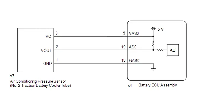
CAUTION / NOTICE / HINT
CAUTION:
Refer to the precautions before inspecting high voltage circuit.
Click here

NOTICE:
-
After the ignition switch is turned off, there may be a waiting time before disconnecting the auxiliary negative (-) battery terminal.
Click here

-
When disconnecting and reconnecting the auxiliary battery.
HINT:
When disconnecting and reconnecting the auxiliary battery, there is an automatic learning function that completes learning when the respective system is used.
Click here

PROCEDURE
| 1. | COMPARE REFRIGERANT GAS PRESSURE VALUES SHOWN ON GTS AND MANIFOLD GAUGE SET |
HINT:
This check is meant to compare the refrigerant gas pressures on the GTS and on the air conditioning tool when the air conditioning is stopped, so do not operate the compressor.
Pre-procedure1
(a) Turn the blower switch off.
(b) Turn the ignition switch off and wait for 1 hour or more.
(c) Install a manifold gauge set.
Procedure1
(d) Read the Data List according to the display on the GTS.
Powertrain > HV Battery > Data List| Tester Display |
|---|
| Hybrid/EV Battery Refrigerant Pressure 1 |
| Result | Proceed to |
|---|---|
| The Data List value matches the value on the manifold gauge set | A |
| The Data List value does not match the value on the manifold gauge set | B |
Post-procedure1
(e) Compare the values displayed in the Data List and on the manifold gauge set.
| B |

| GO TO STEP 5 |
|

| 2. | REFRIGERANT SHORTAGE CHECK USING GTS |
HINT:
Click here

| OK |

| GO TO STEP 5 |
|

| 3. | CHARGE REFRIGERANT GAS OR REPAIR REFRIGERANT GAS LEAK |
HINT:
Click here

|

| 4. | CHECK DTC OUTPUT (HV BATTERY) |
Pre-procedure1
(a) None
Procedure1
(b) Check for DTCs.
Powertrain > HV Battery > Trouble Codes| Result | Proceed to |
|---|---|
| P1B8312 or P1B8314 is output | A |
| P1B8312 or P1B8314 is not output | B |
Post-procedure1
(c) Turn the ignition switch off.
| A |

| GO TO STEP 5 |
| B |

| END |
| 5. | CHECK HARNESS AND CONNECTOR (AIR CONDITIONING PRESSURE SENSOR POWER SOURCE CIRCUIT) |
NOTICE:
Be sure to wear insulated gloves and protective goggles.
Pre-procedure1
(a) Check that the service plug grip is not installed.
NOTICE:
After removing the service plug grip, do not turn the ignition switch to ON (READY), unless instructed by the repair manual because this may cause a malfunction.
(b) Connect the SST.
HINT:
Click here

| (c) Disconnect the air conditioning pressure sensor (No. 2 traction battery cooler tube) connector. NOTICE: Before disconnecting the connector, check that it is not loose or disconnected. |
|

(d) Connect the cable to the negative (-) auxiliary battery terminal.
(e) Turn the ignition switch to ON.
Procedure1
(f) Measure the voltage according to the value(s) in the table below.
Standard Voltage:
 Click Location & Routing(x7) Click Connector(x7)
 | Tester Connection | Condition | Specified Condition | Result |
|---|---|---|---|
| x7-3 (VC) - x7-1 (GND) | Ignition switch ON | 4.75 to 5.25 V | V |
| x7-2 (VOUT) - x7-1 (GND) | Ignition switch ON | 4.75 to 5.25 V | V |
| x7-3 (VC) - body ground | Ignition switch ON | 4.75 to 5.25 V | V |
| x7-2 (VOUT) - body ground | Ignition switch ON | 4.75 to 5.25 V | V |
NOTICE:
- Turning the ignition switch to ON with the service plug grip removed causes other DTCs to be stored. Clear the DTCs after performing this inspection.
- If the ignition switch is turned to ON with the connectors disconnected, other DTCs will be stored. Be sure to clear the DTCs after the inspection.
Post-procedure1
(g) Turn the ignition switch off.
(h) Disconnect the cable from the negative (-) auxiliary battery terminal.
(i) Reconnect the air conditioning pressure sensor (No. 2 traction battery cooler tube) connector.
(j) Disconnect the SST.
| OK |

| REPLACE AIR CONDITIONING PRESSURE SENSOR (NO. 2 TRACTION BATTERY COOLER TUBE) |
|

| 6. | CHECK HARNESS AND CONNECTOR (AIR CONDITIONING PRESSURE SENSOR (NO. 2 TRACTION BATTERY COOLER TUBE) - BATTERY ECU ASSEMBLY) |
NOTICE:
Be sure to wear insulated gloves and protective goggles.
Pre-procedure1
(a) Check that the service plug grip is not installed.
NOTICE:
After removing the service plug grip, do not turn the ignition switch to ON (READY), unless instructed by the repair manual because this may cause a malfunction.
| (b) Disconnect the battery ECU assembly connector. NOTICE: Before disconnecting the connector, check that it is not loose or disconnected. |
|

| (c) Disconnect the air conditioning pressure sensor connector. NOTICE: Before disconnecting the connector, check that it is not loose or disconnected. |
|
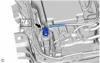
Procedure1
(d) Measure the resistance according to the value(s) in the table below.
Standard Resistance:
 Click Location & Routing(x7,x4) Click Connector(x7) Click Connector(x4)
 | Tester Connection | Condition | Specified Condition | Result |
|---|---|---|---|
| x7-3 (VC) - x4-5 (VAS0) | Ignition switch off | Below 1 Ω | Ω |
| x7-2 (VOUT) - x4-19 (AS0) | Ignition switch off | Below 1 Ω | Ω |
| x7-1 (GND) - x4-18 (GAS0) | Ignition switch off | Below 1 Ω | Ω |
| x7-3 (VC) or x4-5 (VAS0) - Other terminals and body ground | Ignition switch off | 10 kΩ or higher | kΩ |
| x7-2 (VOUT) or x4-19 (AS0) - Other terminals and body ground | Ignition switch off | 10 kΩ or higher | kΩ |
| x7-1 (GND) or x4-18 (GAS0) - Other terminals and body ground | Ignition switch off | 10 kΩ or higher | kΩ |
Post-procedure1
(e) Reconnect the battery ECU assembly connector.
(f) Reconnect the air conditioning pressure sensor connector.
| OK |

| REPLACE BATTERY ECU ASSEMBLY |
| NG |

| REPAIR OR REPLACE HARNESS OR CONNECTOR |
Hybrid/EV Battery Pack Refrigerant Pressure Sensor "A" Circuit Range/Performance Circuit Voltage Out of Range (P1B831C)
DTC SUMMARY
MALFUNCTION DESCRIPTION
Determines that there is a deviation in characteristics for the HV battery outlet pressure sensor installed in the HV battery refrigerant cooling system to prevent the HV battery temperature from rising excessively.
DESCRIPTION
| DTC No. | Detection Item | DTC Detection Condition | Trouble Area | MIL | Warning Indicate | DTC Output from | Priority | Note |
|---|---|---|---|---|---|---|---|---|
| P1B831C | Hybrid/EV Battery Pack Refrigerant Pressure Sensor "A" Circuit Range/Performance Circuit Voltage Out of Range | While HV battery refrigerant is cooling, the difference between the values of the HV battery refrigerant inlet temperature converted to pressure and the HV battery refrigerant pressure sensor is the specified value or higher (2 trip detection logic) |
| Comes on | Master Warning: Comes on | HV Battery | A | SAE Code: P1B84 |
MONITOR DESCRIPTION
While battery refrigerant is cooling, if the difference between the values of the battery refrigerant inlet temperature converted to pressure and the battery refrigerant pressure sensor is the specified value or higher, the battery ECU assembly illuminates the MIL and stores a DTC.
MONITOR STRATEGY
| Related DTCs | P1B84 (INF P1B831C): Hybrid/EV Battery Pack Refrigerant Pressure Sensor "A" Circuit Range/Performance |
| Required sensors/components | Air conditioning pressure sensor, Air Conditioning Thermistor |
| Frequency of operation | Continuous |
| Duration | TMC's intellectual property |
| MIL operation | 2 driving cycles |
| Sequence of operation | None |
TYPICAL ENABLING CONDITIONS
| The monitor will run whenever the following DTCs are not stored | TMC's intellectual property |
| Other conditions belong to TMC's intellectual property | - |
TYPICAL MALFUNCTION THRESHOLDS
| TMC's intellectual property | - |
COMPONENT OPERATING RANGE
| Battery ECU assembly | DTC P1B84 (INF P1B831C) is not detected |
CONFIRMATION DRIVING PATTERN
HINT:
-
After repair has been completed, clear the DTC and then check that the Toyota Prius vehicle has returned to normal by performing the following All Readiness check procedure.
Click here

-
When clearing the permanent DTCs, refer to the "CLEAR PERMANENT DTC" procedure.
Click here

- Clear the DTCs (even if no DTCs are stored, perform the clear DTC procedure).
- Turn the ignition switch off and wait for 2 minutes or more.
- Enter the following menus: Powertrain / HV Battery / Active Test / Hybrid/EV Battery Refrigerant Cooling Control.
-
Perform the "Hybrid/EV Battery Refrigerant Cooling Control" Active Test for 14 minutes.[*1]
HINT:
-
In order to perform "Hybrid/EV Battery Refrigerant Cooling Control", the HV battery minimum temperature must be 11°C (52°F) and the refrigerant temperature inside the HV battery must be 0°C (32°F) or higher.
If the above conditions are not established, perform the "Hybrid/EV Battery Heater Relay" Active Test in an environment with an ambient temperature of 5°C (41°F) or higher and increase the HV battery temperature.
In consideration of the temperature drop after the heater stops, increase the value of Data List item "Hybrid/EV Battery Temperature 1 to 15" to a minimum of 12°C (54°F) or more, and the value of Data List item "Hybrid/EV Battery Refrigerant Temperature (Duct Inlet 1)" and "Hybrid/EV Battery Refrigerant Temperature (Duct Outlet 1)" to 1°C (34°F) or more.
(At an ambient temperature of 5°C (41°F), "Hybrid/EV Battery Heater Relay" will need to be performed for approximately 5 hours.)
- Perform this step with the A/C blower switch off.
-
[*1]: Normal judgment procedure.
The normal judgment procedure is used to complete DTC judgment and also used when clearing permanent DTCs.
-
In order to perform "Hybrid/EV Battery Refrigerant Cooling Control", the HV battery minimum temperature must be 11°C (52°F) and the refrigerant temperature inside the HV battery must be 0°C (32°F) or higher.
- Enter the following menus: Powertrain / HV Battery / Utility / All Readiness.
-
Check the DTC judgment result.
HINT:
- If the judgment result shows NORMAL, the system is normal.
- If the judgment result shows ABNORMAL, the system has a malfunction.
- If the judgment result shows INCOMPLETE or N/A, perform the normal judgment procedure again.
WIRING DIAGRAM
Refer to the wiring diagram for DTC P1B8312.
Click here

CAUTION / NOTICE / HINT
CAUTION:
Refer to the precautions before inspecting high voltage circuit.
Click here

NOTICE:
-
After the ignition switch is turned off, there may be a waiting time before disconnecting the auxiliary negative (-) battery terminal.
Click here

-
When disconnecting and reconnecting the auxiliary battery.
HINT:
When disconnecting and reconnecting the auxiliary battery, there is an automatic learning function that completes learning when the respective system is used.
Click here

PROCEDURE
| 1. | CHECK DTC OUTPUT (HV BATTERY, HYBRID CONTROL, AIR CONDITIONER) |
Pre-procedure1
(a) None
Procedure1
(b) Check for DTCs.
Powertrain > HV Battery > Trouble Codes Powertrain > Hybrid Control > Trouble Codes Body Electrical > Air Conditioner > Trouble Codes| Result | Proceed to |
|---|---|
| "P1B831C" only is output, or DTCs except the ones in the table below are also output. | A |
| DTCs of hybrid battery system in the table below are output. | B |
| DTCs of hybrid control system in the table below are output. | C |
| DTCs of air conditioning system in the table below are output. | D |
| Malfunction Content | System | Relevant DTC | |
|---|---|---|---|
| Air conditioner malfunction | Air conditioning system | B138571 | A/C Cooling Electric Expansion Valve Actuator Stuck |
| B149887 | A/C Inverter Local Missing Message | ||
| B3A0A71 | A/C Heating Electric Expansion Valve Actuator Stuck | ||
| P0EC971 | A/C Low Pressure Magnetic Valve Actuator Stuck | ||
| P2D4496 | A/C Compressor Component Internal Failure | ||
| Microcomputer malfunction | Hybrid battery system | P060A47 | Hybrid/EV Battery Energy Control Module Monitoring Processor Watchdog / Safety MCU Failure |
| P060B49 | Hybrid/EV Battery Energy Control Module A/D Processing Internal Electronic Failure | ||
| P060687 | Hybrid/EV Battery Energy Control Module Processor to Monitoring Processor Missing Message | ||
| Hybrid control system | P0A1F94 | Hybrid/EV Battery Energy Control Module Unexpected Operation | |
| Sensor and actuator circuit malfunction | Hybrid battery system | P0CDF73 | Hybrid/EV Battery Pack Coolant Control Valve "A" Stuck On Actuator Stuck Closed |
| P0D1A71 | Hybrid/EV Battery Pack Coolant Control Valve "B" Performance/Stuck Off Actuator Stuck | ||
| P0DE871 | Hybrid/EV Battery Pack Coolant Control Valve "C" Performance/Stuck Off Actuator Stuck | ||
Post-procedure1
(c) Turn the ignition switch off.
| B |

| GO TO DTC CHART (HYBRID BATTERY SYSTEM) |
| C |

| GO TO DTC CHART (HYBRID CONTROL SYSTEM) |
| D |

| GO TO DTC CHART (AIR CONDITIONING SYSTEM) |
|

| 2. | REFRIGERANT SHORTAGE CHECK USING GTS |
HINT:
Click here

| NG |

| GO TO STEP 5 |
|

| 3. | CHECK HARNESS AND CONNECTOR (AIR CONDITIONING PRESSURE SENSOR POWER SOURCE CIRCUIT) |
Click here

| OK |

| REPLACE AIR CONDITIONING PRESSURE SENSOR (NO. 2 TRACTION BATTERY COOLER TUBE) |
|

| 4. | CHECK HARNESS AND CONNECTOR (AIR CONDITIONING PRESSURE SENSOR (NO. 2 TRACTION BATTERY COOLER TUBE) - BATTERY ECU ASSEMBLY) |
Click here

| OK |

| REPLACE BATTERY ECU ASSEMBLY |
| NG |

| REPAIR OR REPLACE HARNESS OR CONNECTOR |
| 5. | INSPECT FOR REFRIGERANT LEAK (AIR CONDITIONING SYSTEM) |
Click here

| NG |

| GO TO PROBLEM SYMPTOMS TABLE (AIR CONDITIONING SYSTEM) |
|

| 6. | INSPECT FOR REFRIGERANT LEAK (INLET SIDE OF HV SUPPLY BATTERY ASSEMBLY) |
Click here

| OK |

| CHECK AND REPLACE REFRIGERANT LEAK (HV SUPPLY BATTERY ASSEMBLY) |
| NG |

| GO TO PROBLEM SYMPTOMS TABLE (AIR CONDITIONING SYSTEM) |
High Voltage Power Resource Internal Electronic Failure (P1C8549)
DESCRIPTION
The battery ECU assembly monitors an internal operation of the hybrid vehicle control ECU. If it detects the following malfunction, it will store this DTC and perform fail-safe control.
| DTC No. | Detection Item | DTC Detection Condition | Trouble Area | MIL | Warning Indicate | DTC Output from | Priority | Note |
|---|---|---|---|---|---|---|---|---|
| P1C8549 | High Voltage Power Resource Internal Electronic Failure | An abnormal signal is detected by the battery ECU assembly (excessive discharging current). (1 trip detection logic) | Hybrid Toyota Prius vehicle control ECU | Does not come on | Master Warning: Comes on | HV Battery | A | SAE Code: P3004 |
CONFIRMATION DRIVING PATTERN
HINT:
After repair has been completed, clear the DTC and then check that the Toyota Prius vehicle has returned to normal by performing the following All Readiness check procedure.
Click here

- Clear the DTCs (even if no DTCs are stored, perform the clear DTC procedure).
- Turn the ignition switch off and wait for 2 minutes or more.
- Drive the Toyota Prius vehicle for approximately 10 minutes according to the freeze frame data items "Vehicle Speed", "Accelerator Position", "Hybrid/EV Battery Current" and "Hybrid/EV Battery Temperature 1 to 15".
- Enter the following menus: Powertrain / HV Battery / Utility / All Readiness.
-
Check the DTC judgment result.
HINT:
- If the judgment result shows NORMAL, the system is normal.
- If the judgment result shows ABNORMAL, the system has a malfunction.
- If the judgment result shows INCOMPLETE or N/A, perform driving pattern again.
PROCEDURE
| 1. | CHECK DTC OUTPUT (HV BATTERY, HYBRID CONTROL) |
Pre-procedure1
(a) None
Procedure1
(b) Check for DTCs.
Powertrain > HV Battery > Trouble Codes Powertrain > Hybrid Control > Trouble Codes| Result | Proceed to |
|---|---|
| "P1C8549" only is output. | A |
| DTCs except "P1C8549" of hybrid battery system are output. | B |
| DTCs except "P1C8549" of hybrid control system are output. | C |
Post-procedure1
(c) Turn the ignition switch off.
| A |

| REPLACE HYBRID Toyota Prius Vehicle CONTROL ECU |
| B |

| GO TO DTC CHART (HYBRID BATTERY SYSTEM) |
| C |

| GO TO DTC CHART (HYBRID CONTROL SYSTEM) |
Hybrid/EV Battery Stack 1 Voltage Difference Out of Range (P1CC81E,P1CC91E,P1CCA1E)
DESCRIPTION
The HV battery is composed of 72 cells (3.7 V each) in series. The battery ECU assembly monitors difference in voltage of each HV battery cell to detect malfunctions of the HV battery.
| DTC No. | Detection Item | DTC Detection Condition | Trouble Area | MIL | Warning Indicate | DTC Output from | Priority | Note |
|---|---|---|---|---|---|---|---|---|
| P1CC81E | Hybrid/EV Battery Stack 1 Voltage Difference Out of Range | The difference in voltage of each cell of the No. 1 HV supply stack sub-assembly exceeds the specified value. (1 trip detection logic) |
| Comes on | Master Warning: Comes on | HV Battery | A | SAE Code: P33DA |
| P1CC91E | Hybrid/EV Battery Stack 2 Voltage Difference Out of Range | The difference in voltage of each cell of the No. 2 HV supply stack sub-assembly exceeds the specified value. (1 trip detection logic) |
| Comes on | Master Warning: Comes on | HV Battery | A | SAE Code: P33DB |
| P1CCA1E | Hybrid/EV Battery Stack 3 Voltage Difference Out of Range | The difference in voltage of each cell of the No. 3 HV supply stack sub-assembly exceeds the specified value. (1 trip detection logic) |
| Comes on | Master Warning: Comes on | HV Battery | A | SAE Code: P33DC |
MONITOR DESCRIPTION
If the difference in voltage between each HV battery cell exceeds the specified value, the battery ECU assembly determines that a malfunction has occurred. When the malfunction detection condition is satisfied, the battery ECU assembly will illuminate the MIL and store a DTC.
MONITOR STRATEGY
| Related DTCs | P33DA (INF P1CC81E), P33DB (INF P1CC91E), P33DC (INF P1CCA1E): Battery cell malfunction |
| Required sensors/components | Battery ECU assembly |
| Frequency of operation | Continuous |
| Duration | TMC's intellectual property |
| MIL operation | 1 driving cycle |
| Sequence of operation | None |
TYPICAL ENABLING CONDITIONS
| The monitor will run whenever the following DTCs are not stored | TMC's intellectual property |
| Other conditions belong to TMC's intellectual property | - |
TYPICAL MALFUNCTION THRESHOLDS
| TMC's intellectual property | - |
COMPONENT OPERATING RANGE
| Battery ECU assembly | DTC P33DA (INF P1CC81E) is not detected DTC P33DB (INF P1CC91E) is not detected DTC P33DC (INF P1CCA1E) is not detected |
CONFIRMATION DRIVING PATTERN
HINT:
-
After repair has been completed, clear the DTC and then check that the Toyota Prius vehicle has returned to normal by performing the following All Readiness check procedure.
Click here

-
When clearing the permanent DTCs, refer to the "CLEAR PERMANENT DTC" procedure.
Click here

- Clear the DTCs (even if no DTCs are stored, perform the clear DTC procedure).
- Turn the ignition switch off and wait for 1 hour or more.[*1]
- Turn the ignition switch to ON and wait for 10 seconds or more.[*2]
-
Drive the Toyota Prius vehicle on urban roads for approximately 10 minutes.[*3]
HINT:
-
[*1] to [*3]: Normal judgment procedure.
The normal judgment procedure is used to complete DTC judgment and also used when clearing permanent DTCs.
- This DTC may not be stored if the vehicle is stopped or being driven at a constant speed.
-
[*1] to [*3]: Normal judgment procedure.
- Enter the following menus: Powertrain / HV Battery / Utility / All Readiness.
-
Check the DTC judgment result.
HINT:
- If the judgment result shows NORMAL, the system is normal.
- If the judgment result shows ABNORMAL, the system has a malfunction.
- If the judgment result shows INCOMPLETE or N/A, perform the normal judgment procedure again.
WIRING DIAGRAM
Refer to the wiring diagram for DTC P1A001C.
Click here

CAUTION / NOTICE / HINT
CAUTION:
Refer to the precautions before inspecting high voltage circuit.
Click here

NOTICE:
-
After the ignition switch is turned off, there may be a waiting time before disconnecting the auxiliary negative (-) battery terminal.
Click here

-
When disconnecting and reconnecting the auxiliary battery.
HINT:
When disconnecting and reconnecting the auxiliary battery, there is an automatic learning function that completes learning when the respective system is used.
Click here

PROCEDURE
| 1. | CHECK DTC OUTPUT (HV BATTERY, HYBRID CONTROL) |
Pre-procedure1
(a) None
Procedure1
(b) Check for DTCs.
Powertrain > HV Battery > Trouble Codes Powertrain > Hybrid Control > Trouble Codes| Result | Proceed to |
|---|---|
| "P1CC81E, P1CC91E or P1CCA1E" only is output, or DTCs except the ones in the table below are also output. | A |
| DTCs of hybrid battery system in the table below are output. | B |
| DTCs of hybrid control system in the table below are output. | C |
| System | Relevant DTC | |
|---|---|---|
| Hybrid battery system | P060A47 | Hybrid/EV Battery Energy Control Module Monitoring Processor Watchdog / Safety MCU Failure |
| P060B49 | Hybrid/EV Battery Energy Control Module A/D Processing Internal Electronic Failure | |
| P060687 | Hybrid/EV Battery Energy Control Module Processor to Monitoring Processor Missing Message | |
| P1AC413 | Hybrid/EV Battery Stack 1 Current Interrupt Device Circuit Open | |
| P1AC513 | Hybrid/EV Battery Stack 2 Current Interrupt Device Circuit Open | |
| P1AC613 | Hybrid/EV Battery Stack 3 Current Interrupt Device Circuit Open | |
| P1AC713 | Hybrid/EV Battery Stack 4 Current Interrupt Device Circuit Open | |
| P1AC49E | Hybrid/EV Battery Stack 1 Current Interrupt Device Stuck On | |
| P1AC59E | Hybrid/EV Battery Stack 2 Current Interrupt Device Stuck On | |
| P1AC69E | Hybrid/EV Battery Stack 3 Current Interrupt Device Stuck On | |
| P1AC79E | Hybrid/EV Battery Stack 4 Current Interrupt Device Stuck On | |
| Hybrid control system | P0A1F94 | Hybrid/EV Battery Energy Control Module Unexpected Operation |
Post-procedure1
(c) Turn the ignition switch off.
| B |

| GO TO DTC CHART (HYBRID BATTERY SYSTEM) |
| C |

| GO TO DTC CHART (HYBRID CONTROL SYSTEM) |
|

| 2. | CHECK DTC |
(a) Check the DTCs that were output when the Toyota Prius vehicle was brought to the workshop.
| Result | Proceed to |
|---|---|
| "P1CC81E" is also output. | A |
| "P1CC91E" is also output. | B |
| "P1CCA1E" is also output. | C |
| B |

| GO TO STEP 14 |
| C |

| GO TO STEP 25 |
|

| 3. | CHECK CONNECTOR CONNECTION CONDITION (BATTERY VOLTAGE SENSOR CONNECTOR) |
CAUTION:
Be sure to wear insulated gloves and protective goggles.
Pre-procedure1
(a) Check that the service plug grip is not installed.
NOTICE:
After removing the service plug grip, do not turn the ignition switch to ON (READY), unless instructed by the repair manual because this may cause a malfunction.
Procedure1
| (b) Check the connections of the battery voltage sensor connectors. HINT: Click here
OK: The connector is connected securely and there are no contact problems. Result:
|
| |||||||||||||


Post-procedure1
(c) None
| B |

| CONNECT SECURELY |
| C |

| REPLACE NO. 1 HV SUPPLY STACK SUB-ASSEMBLY |
|

| 4. | CHECK FREEZE FRAME DATA |
Pre-procedure1
(a) None
Procedure1
(b) Read the value of freeze frame data items "Hybrid/EV Battery Cell 1 Voltage" through "Hybrid/EV Battery Cell 24 Voltage" for DTC P1CC81E and make a note if the value of any is the lowest voltage value.
Powertrain > HV Battery > Trouble CodesPost-procedure1
(c) Turn the ignition switch off.
|

| 5. | CHECK BATTERY VOLTAGE SENSOR (VA1 - VA24) |
Click here

| Result | Proceed to |
|---|---|
| The resistance between the terminals is 50 kΩ or more. | A |
| Other than above | B |
| B |

| REPLACE BATTERY VOLTAGE SENSOR |
|

| 6. | CHECK TOTAL DISTANCE DRIVEN |
(a) Read the odometer to check the total distance the Toyota Prius vehicle has been driven.
| Result | Proceed to | |
|---|---|---|
| Total distance driven is less than 200000 km (124280 mile) | A | |
| Total distance driven is 200000 km (124280 mile) or more | Current total distance driven - total distance driven when service plug grip replaced = less than 200000 km (124280 mile) *1 | |
| Other than above | B | |
HINT:
*1: If the service plug grip has been replaced, use the total distance driven since it was replaced.
| B |

| GO TO STEP 10 |
|

| 7. | REPLACE NO. 1 HV SUPPLY STACK SUB-ASSEMBLY |
HINT:
Click here

|

| 8. | SIMULATION TEST |
Pre-procedure1
(a) None
Procedure1
(b) Clear the DTCs and freeze frame data.
Powertrain > HV Battery > Clear DTCsPost-procedure1
(c) Turn the ignition switch to ON and wait for 10 seconds or more.
(d) Drive the Toyota Prius vehicle on urban roads for approximately 10 minutes.
(e) Turn the ignition switch off.
|

| 9. | CHECK DTC OUTPUT (HV BATTERY) |
Pre-procedure1
(a) None
Procedure1
(b) Check if DTCs are output.
Powertrain > HV Battery > Trouble Codes| Result | Proceed to |
|---|---|
| "P1CC81E" is output. | A |
| "P1CC81E" is not output. | B |
Post-procedure1
(c) Turn the ignition switch off.
| A |

| REPLACE BATTERY VOLTAGE SENSOR |
| B |

| END |
| 10. | REPLACE NO. 1 HV SUPPLY STACK SUB-ASSEMBLY |
HINT:
Click here

|

| 11. | REPLACE SERVICE PLUG GRIP |
HINT:
Click here

|

| 12. | SIMULATION TEST |
Pre-procedure1
(a) None
Procedure1
(b) Clear the DTCs and freeze frame data.
Powertrain > HV Battery > Clear DTCsPost-procedure1
(c) Turn the ignition switch to ON and wait for 10 seconds or more.
(d) Drive the Toyota Prius vehicle on urban roads for approximately 10 minutes.
(e) Turn the ignition switch off.
|

| 13. | CHECK DTC OUTPUT (HV BATTERY) |
Pre-procedure1
(a) None
Procedure1
(b) Check if DTCs are output.
Powertrain > HV Battery > Trouble Codes| Result | Proceed to |
|---|---|
| "P1CC81E" is output. | A |
| "P1CC81E" is not output. | B |
Post-procedure1
(c) Turn the ignition switch off.
| A |

| REPLACE BATTERY VOLTAGE SENSOR |
| B |

| END |
| 14. | CHECK CONNECTOR CONNECTION CONDITION (BATTERY VOLTAGE SENSOR CONNECTOR) |
CAUTION:
Be sure to wear insulated gloves and protective goggles.
Pre-procedure1
(a) Check that the service plug grip is not installed.
NOTICE:
After removing the service plug grip, do not turn the ignition switch to ON (READY), unless instructed by the repair manual because this may cause a malfunction.
Procedure1
| (b) Check the connections of the battery voltage sensor connectors. HINT: Click here
OK: The connector is connected securely and there are no contact problems. Result:
|
| |||||||||||||


Post-procedure1
(c) None
| B |

| CONNECT SECURELY |
| C |

| REPLACE NO. 2 HV SUPPLY STACK SUB-ASSEMBLY |
|

| 15. | CHECK FREEZE FRAME DATA |
Pre-procedure1
(a) None
Procedure1
(b) Read the value of freeze frame data items "Hybrid/EV Battery Cell 25 Voltage" through "Hybrid/EV Battery Cell 48 Voltage" for DTC P1CC91E and make a note if the value of any is the lowest voltage value.
Powertrain > HV Battery > Trouble CodesPost-procedure1
(c) Turn the ignition switch off.
|

| 16. | CHECK BATTERY VOLTAGE SENSOR (VA25 - VA48) |
Click here

| Result | Proceed to |
|---|---|
| The resistance between the terminals is 50 kΩ or more. | A |
| Other than above | B |
| B |

| REPLACE BATTERY VOLTAGE SENSOR |
|

| 17. | CHECK TOTAL DISTANCE DRIVEN |
(a) Read the odometer to check the total distance the Toyota Prius vehicle has been driven.
| Result | Proceed to | |
|---|---|---|
| Total distance driven is less than 200000 km (124280 mile) | A | |
| Total distance driven is 200000 km (124280 mile) or more | Current total distance driven - total distance driven when service plug grip replaced = less than 200000 km (124280 mile) *1 | |
| Other than above | B | |
HINT:
*1: If the service plug grip has been replaced, use the total distance driven since it was replaced.
| B |

| GO TO STEP 21 |
|

| 18. | REPLACE NO. 2 HV SUPPLY STACK SUB-ASSEMBLY |
HINT:
Click here

|

| 19. | SIMULATION TEST |
Pre-procedure1
(a) None
Procedure1
(b) Clear the DTCs and freeze frame data.
Powertrain > HV Battery > Clear DTCsPost-procedure1
(c) Turn the ignition switch to ON and wait for 10 seconds or more.
(d) Drive the Toyota Prius vehicle on urban roads for approximately 10 minutes.
(e) Turn the ignition switch off.
|

| 20. | CHECK DTC OUTPUT (HV BATTERY) |
Pre-procedure1
(a) None
Procedure1
(b) Check if DTCs are output.
Powertrain > HV Battery > Trouble Codes| Result | Proceed to |
|---|---|
| "P1CC91E" is output. | A |
| "P1CC91E" is not output. | B |
Post-procedure1
(c) Turn the ignition switch off.
| A |

| REPLACE BATTERY VOLTAGE SENSOR |
| B |

| END |
| 21. | REPLACE NO. 2 HV SUPPLY STACK SUB-ASSEMBLY |
HINT:
Click here

|

| 22. | REPLACE SERVICE PLUG GRIP |
HINT:
Click here

|

| 23. | SIMULATION TEST |
Pre-procedure1
(a) None
Procedure1
(b) Clear the DTCs and freeze frame data.
Powertrain > HV Battery > Clear DTCsPost-procedure1
(c) Turn the ignition switch to ON and wait for 10 seconds or more.
(d) Drive the Toyota Prius vehicle on urban roads for approximately 10 minutes.
(e) Turn the ignition switch off.
|

| 24. | CHECK DTC OUTPUT (HV BATTERY) |
Pre-procedure1
(a) None
Procedure1
(b) Check if DTCs are output.
Powertrain > HV Battery > Trouble Codes| Result | Proceed to |
|---|---|
| "P1CC91E" is output. | A |
| "P1CC91E" is not output. | B |
Post-procedure1
(c) Turn the ignition switch off.
| A |

| REPLACE BATTERY VOLTAGE SENSOR |
| B |

| END |
| 25. | CHECK CONNECTOR CONNECTION CONDITION (BATTERY VOLTAGE SENSOR CONNECTOR) |
CAUTION:
Be sure to wear insulated gloves and protective goggles.
Pre-procedure1
(a) Check that the service plug grip is not installed.
NOTICE:
After removing the service plug grip, do not turn the ignition switch to ON (READY), unless instructed by the repair manual because this may cause a malfunction.
Procedure1
| (b) Check the connections of the battery voltage sensor connectors. HINT: Click here
OK: The connector is connected securely and there are no contact problems. Result:
|
| |||||||||||||


Post-procedure1
(c) None
| B |

| CONNECT SECURELY |
| C |

| REPLACE NO. 3 HV SUPPLY STACK SUB-ASSEMBLY |
|

| 26. | CHECK FREEZE FRAME DATA |
Pre-procedure1
(a) None
Procedure1
(b) Read the value of freeze frame data items "Hybrid/EV Battery Cell 49 Voltage" through "Hybrid/EV Battery Cell 72 Voltage" for DTC P1CCA1E and make a note if the value of any is the lowest voltage value.
Powertrain > HV Battery > Trouble CodesPost-procedure1
(c) Turn the ignition switch off.
|

| 27. | CHECK BATTERY VOLTAGE SENSOR (VA49 - VA72) |
Click here

| Result | Proceed to |
|---|---|
| The resistance between the terminals is 50 kΩ or more. | A |
| Other than above | B |
| B |

| REPLACE BATTERY VOLTAGE SENSOR |
|

| 28. | CHECK TOTAL DISTANCE DRIVEN |
(a) Read the odometer to check the total distance the Toyota Prius vehicle has been driven.
| Result | Proceed to | |
|---|---|---|
| Total distance driven is less than 200000 km (124280 mile) | A | |
| Total distance driven is 200000 km (124280 mile) or more | Current total distance driven - total distance driven when service plug grip replaced = less than 200000 km (124280 mile) *1 | |
| Other than above | B | |
HINT:
*1: If the service plug grip has been replaced, use the total distance driven since it was replaced.
| B |

| GO TO STEP 32 |
|

| 29. | REPLACE NO. 3 HV SUPPLY STACK SUB-ASSEMBLY |
HINT:
Click here

|

| 30. | SIMULATION TEST |
Pre-procedure1
(a) None
Procedure1
(b) Clear the DTCs and freeze frame data.
Powertrain > HV Battery > Clear DTCsPost-procedure1
(c) Turn the ignition switch to ON and wait for 10 seconds or more.
(d) Drive the Toyota Prius vehicle on urban roads for approximately 10 minutes.
(e) Turn the ignition switch off.
|

| 31. | CHECK DTC OUTPUT (HV BATTERY) |
Pre-procedure1
(a) None
Procedure1
(b) Check if DTCs are output.
Powertrain > HV Battery > Trouble Codes| Result | Proceed to |
|---|---|
| "P1CCA1E" is output. | A |
| "P1CCA1E" is not output. | B |
Post-procedure1
(c) Turn the ignition switch off.
| A |

| REPLACE BATTERY VOLTAGE SENSOR |
| B |

| END |
| 32. | REPLACE NO. 3 HV SUPPLY STACK SUB-ASSEMBLY |
HINT:
Click here

|

| 33. | REPLACE SERVICE PLUG GRIP |
HINT:
Click here

|

| 34. | SIMULATION TEST |
Pre-procedure1
(a) None
Procedure1
(b) Clear the DTCs and freeze frame data.
Powertrain > HV Battery > Clear DTCsPost-procedure1
(c) Turn the ignition switch to ON and wait for 10 seconds or more.
(d) Drive the Toyota Prius vehicle on urban roads for approximately 10 minutes.
(e) Turn the ignition switch off.
|

| 35. | CHECK DTC OUTPUT (HV BATTERY) |
Pre-procedure1
(a) None
Procedure1
(b) Check if DTCs are output.
Powertrain > HV Battery > Trouble Codes| Result | Proceed to |
|---|---|
| "P1CCA1E" is output. | A |
| "P1CCA1E" is not output. | B |
Post-procedure1
(c) Turn the ignition switch off.
| A |

| REPLACE BATTERY VOLTAGE SENSOR |
| B |

| END |
Hybrid/EV Battery Pack Current Sensor "C" Circuit Range/Performance Circuit Voltage Out of Range (P2BE41C)
DESCRIPTION
Refer to the description for DTC P0ABF11.
Click here

| DTC No. | Detection Item | DTC Detection Condition | Trouble Area | MIL | Warning Indicate | DTC Output from | Priority | Note |
|---|---|---|---|---|---|---|---|---|
| P2BE41C | Hybrid/EV Battery Pack Current Sensor "C" Circuit Range/Performance Circuit Voltage Out of Range | A battery current sensor is malfunctioning.*1 (1 trip detection logic) |
| Comes on | Master Warning: Comes on | HV Battery | A | SAE Code: P2BE5 |
*1: The difference in output of the main and low battery current sensors is large.
MONITOR DESCRIPTION
If the battery ECU assembly detects a malfunction in the battery current sensor, the battery ECU assembly illuminates the MIL and stores a DTC.
MONITOR STRATEGY
| Related DTCs | P2BE5 (INF P2BE41C): Hybrid/EV Battery Pack Current sensor malfunction (offset) |
| Required sensors/components | Battery current sensor |
| Frequency of operation | Continuous |
| Duration | TMC's intellectual property |
| MIL operation | 1 driving cycle |
| Sequence of operation | None |
TYPICAL ENABLING CONDITIONS
| The monitor will run whenever the following DTCs are not stored | TMC's intellectual property |
| Other conditions belong to TMC's intellectual property | - |
TYPICAL MALFUNCTION THRESHOLDS
| TMC's intellectual property | - |
COMPONENT OPERATING RANGE
| Battery ECU assembly | DTC P2BE5 (INF P2BE41C) is not detected |
CONFIRMATION DRIVING PATTERN
HINT:
-
After repair has been completed, clear the DTC and then check that the Toyota Prius vehicle has returned to normal by performing the following All Readiness check procedure.
Click here

-
When clearing the permanent DTCs, refer to the "CLEAR PERMANENT DTC" procedure.
Click here

- Clear the DTCs (even if no DTCs are stored, perform the clear DTC procedure).
- Turn the ignition switch off and wait for 2 minutes or more.
-
Drive the Toyota Prius vehicle on urban roads for approximately 10 minutes.[*1]
HINT:
[*1]: Normal judgment procedure.
The normal judgment procedure is used to complete DTC judgment and also used when clearing permanent DTCs.
- Enter the following menus: Powertrain / HV Battery / Utility / All Readiness.
-
Check the DTC judgment result.
HINT:
- If the judgment result shows NORMAL, the system is normal.
- If the judgment result shows ABNORMAL, the system has a malfunction.
- If the judgment result shows INCOMPLETE or N/A, perform the normal judgment procedure again.
WIRING DIAGRAM
Refer to the wiring diagram for P0ABF11.
Click here

CAUTION / NOTICE / HINT
CAUTION:
Refer to the precautions before inspecting high voltage circuit.
Click here

NOTICE:
-
After the ignition switch is turned off, there may be a waiting time before disconnecting the auxiliary negative (-) battery terminal.
Click here

-
When disconnecting and reconnecting the auxiliary battery.
HINT:
When disconnecting and reconnecting the auxiliary battery, there is an automatic learning function that completes learning when the respective system is used.
Click here

PROCEDURE
| 1. | CHECK DTC OUTPUT (HV BATTERY, HYBRID CONTROL) |
Pre-procedure1
(a) None
Procedure1
(b) Check for DTCs.
Powertrain > HV Battery > Trouble Codes Powertrain > Hybrid Control > Trouble Codes| Result | Proceed to |
|---|---|
| "P2BE41C" only is output, or DTCs except the ones in the table below are also output. | A |
| DTCs of hybrid battery system in the table below are output. | B |
| DTCs of hybrid control system in the table below are output. | C |
| System | Relevant DTC | |
|---|---|---|
| Hybrid battery system | P060A47 | Hybrid/EV Battery Energy Control Module Monitoring Processor Watchdog / Safety MCU Failure |
| P060B49 | Hybrid/EV Battery Energy Control Module A/D Processing Internal Electronic Failure | |
| P060687 | Hybrid/EV Battery Energy Control Module Processor to Monitoring Processor Missing Message | |
| Hybrid control system | P0A1F94 | Hybrid/EV Battery Energy Control Module Unexpected Operation |
Post-procedure1
(c) Turn the ignition switch off.
| B |

| GO TO DTC CHART (HYBRID BATTERY SYSTEM) |
| C |

| GO TO DTC CHART (HYBRID CONTROL SYSTEM) |
|

| 2. | CHECK HARNESS AND CONNECTOR (BATTERY ECU ASSEMBLY - NO. 1 TRACTION BATTERY DEVICE BOX ASSEMBLY) |
CAUTION:
Be sure to wear insulated gloves and protective goggles.
Pre-procedure1
(a) Check that the service plug grip is not installed.
NOTICE:
After removing the service plug grip, do not turn the ignition switch to ON (READY), unless instructed by the repair manual because this may cause a malfunction.
| (b) Disconnect the battery ECU assembly connector. NOTICE: Before disconnecting the connector, check that it is not loose or disconnected. |
|

| (c) Disconnect the battery current sensor connector from the No. 1 traction battery device box assembly. NOTICE: Before disconnecting the connector, check that it is not loose or disconnected. |
|

Procedure1
(d) Measure the resistance according to the value(s) in the tables below.
Standard Resistance (Check for Open):
 Click Location & Routing(x11,x4) Click Connector(x11) Click Connector(x4)
 | Tester Connection | Condition | Specified Condition |
|---|---|---|
| x11-1 (IBL) - x4-15 (IBL) | Ignition switch off | Below 1 Ω |
| x11-5 (IB1) - x4-17 (IB1) | Ignition switch off | Below 1 Ω |
| x11-4 (GIB) - x4-14 (GIB) | Ignition switch off | Below 1 Ω |
| x11-3 (IB0) - x4-16 (IB0) | Ignition switch off | Below 1 Ω |
| x11-2 (VIB) - x4-4 (VIB) | Ignition switch off | Below 1 Ω |
Standard Resistance (Check for Short):
 Click Location & Routing(x11,x4) Click Connector(x11) Click Connector(x4)
 | Tester Connection | Condition | Specified Condition |
|---|---|---|
| x11-1 (IBL) or x4-15 (IBL) - Body ground and other terminals | Ignition switch off | 10 kΩ or higher |
| x11-5 (IB1) or x4-17 (IB1) - Body ground and other terminals | Ignition switch off | 10 kΩ or higher |
| x11-4 (GIB) or x4-14 (GIB) - Body ground and other terminals | Ignition switch off | 10 kΩ or higher |
| x11-3 (IB0) or x4-16 (IB0) - Body ground and other terminals | Ignition switch off | 10 kΩ or higher |
| x11-2 (VIB) or x4-4 (VIB) - Body ground and other terminals | Ignition switch off | 10 kΩ or higher |
Post-procedure1
(e) Reconnect the battery current sensor connector to the No. 1 traction battery device box assembly.
(f) Reconnect the battery ECU assembly connector.
| NG |

| REPAIR OR REPLACE HARNESS OR CONNECTOR |
|

| 3. | REPLACE NO. 1 TRACTION BATTERY DEVICE BOX ASSEMBLY |
HINT:
Click here

|

| 4. | CLEAR DTC (HV BATTERY) |
Pre-procedure1
(a) None
Procedure1
(b) Clear the DTCs and freeze frame data.
Powertrain > HV Battery > Clear DTCsPost-procedure1
(c) Perform a road test.
|

| 5. | CHECK DTC OUTPUT (HV BATTERY) |
(a) Check for DTCs.
Powertrain > HV Battery > Trouble Codes| Result | Proceed to |
|---|---|
| DTCs are not output. | A |
| P2BE41C is also output. | B |
| A |

| END |
| B |

| REPLACE BATTERY ECU ASSEMBLY |
Hybrid/EV Battery Pack Current Sensor "C" Circuit Range/Performance Signal Bias Level Out of Range / Zero Adjustment Failure (P2BE428)
DESCRIPTION
Refer to the description for DTC P0ABF11.
Click here

| DTC No. | Detection Item | DTC Detection Condition | Trouble Area | MIL | Warning Indicate | DTC Output from | Priority | Note |
|---|---|---|---|---|---|---|---|---|
| P2BE428 | Hybrid/EV Battery Pack Current Sensor "C" Circuit Range/Performance Signal Bias Level Out of Range / Zero Adjustment Failure | The offset value of the battery current sensor is excessively large. (1 trip detection logic) |
| Comes on | Master Warning: Comes on | HV Battery | A | SAE Code: P2BE5 |
When the ignition switch is ON, normally the HV battery current does not flow. If the HV battery current value is above the specification, this DTC will be stored.
HINT:
-
Make sure to perform Current Sensor Offset Learning after replacing a battery current sensor.
Click here

- This DTC may be output if Current Sensor Offset Learning has not been completed.
MONITOR DESCRIPTION
If the battery ECU assembly detects a malfunction in the battery current sensor, the battery ECU assembly illuminates the MIL and stores a DTC.
MONITOR STRATEGY
| Related DTCs | P2BE5 (INF P2BE428): Hybrid/EV Battery Pack Current sensor malfunction (gain) |
| Required sensors/components | Battery current sensor |
| Frequency of operation | Continuous |
| Duration | TMC's intellectual property |
| MIL operation | 1 driving cycle |
| Sequence of operation | None |
TYPICAL ENABLING CONDITIONS
| The monitor will run whenever the following DTCs are not stored | TMC's intellectual property |
| Other conditions belong to TMC's intellectual property | - |
TYPICAL MALFUNCTION THRESHOLDS
| TMC's intellectual property | - |
COMPONENT OPERATING RANGE
| Battery ECU assembly | DTC P2BE5 (INF P2BE428) is not detected |
CONFIRMATION DRIVING PATTERN
HINT:
-
After repair has been completed, clear the DTC and then check that the Toyota Prius vehicle has returned to normal by performing the following All Readiness check procedure.
Click here

-
When clearing the permanent DTCs, refer to the "CLEAR PERMANENT DTC" procedure.
Click here

- Clear the DTCs (even if no DTCs are stored, perform the clear DTC procedure).
- Turn the ignition switch off and wait for 2 minutes or more.
- Drive the Toyota Prius vehicle on urban roads for approximately 10 minutes.[*1]
- Turn the ignition switch off and wait for 2 minutes or more.[*2]
-
Turn the ignition switch to ON and wait for 10 seconds or more.[*3]
HINT:
[*1] to [*3]: Normal judgment procedure.
The normal judgment procedure is used to complete DTC judgment and also used when clearing permanent DTCs.
- Enter the following menus: Powertrain / HV Battery / Utility / All Readiness.
-
Check the DTC judgment result.
HINT:
- If the judgment result shows NORMAL, the system is normal.
- If the judgment result shows ABNORMAL, the system has a malfunction.
- If the judgment result shows INCOMPLETE or N/A, perform the normal judgment procedure again.
WIRING DIAGRAM
Refer to the wiring diagram for DTC P0ABF11.
Click here

CAUTION / NOTICE / HINT
CAUTION:
Refer to the precautions before inspecting high voltage circuit.
Click here

NOTICE:
-
After the ignition switch is turned off, there may be a waiting time before disconnecting the auxiliary negative (-) battery terminal.
Click here

-
When disconnecting and reconnecting the auxiliary battery.
HINT:
When disconnecting and reconnecting the auxiliary battery, there is an automatic learning function that completes learning when the respective system is used.
Click here

PROCEDURE
| 1. | CHECK DTC OUTPUT (HV BATTERY, HYBRID CONTROL) |
Pre-procedure1
(a) None
Procedure1
(b) Check for DTCs.
Powertrain > HV Battery > Trouble Codes Powertrain > Hybrid Control > Trouble Codes| Result | Proceed to |
|---|---|
| "P2BE428" only is output, or DTCs except the ones in the table below are also output. | A |
| DTCs of hybrid battery system in the table below are output. | B |
| DTCs of hybrid control system in the table below are output. | C |
| System | Relevant DTC | |
|---|---|---|
| Hybrid battery system | P060A47 | Hybrid/EV Battery Energy Control Module Monitoring Processor Watchdog / Safety MCU Failure |
| P060B49 | Hybrid/EV Battery Energy Control Module A/D Processing Internal Electronic Failure | |
| P060687 | Hybrid/EV Battery Energy Control Module Processor to Monitoring Processor Missing Message | |
| P062F46 | Hybrid/EV Battery Energy Control Module EEPROM Calibration / Parameter Memory Failure | |
| Hybrid control system | P0A1F94 | Hybrid/EV Battery Energy Control Module Unexpected Operation |
Post-procedure1
(c) Turn the ignition switch off.
| B |

| GO TO DTC CHART (HYBRID BATTERY SYSTEM) |
| C |

| GO TO DTC CHART (HYBRID CONTROL SYSTEM) |
|

| 2. | CHECK HARNESS AND CONNECTOR (BATTERY ECU ASSEMBLY - NO. 1 TRACTION BATTERY DEVICE BOX ASSEMBLY) |
Click here

| NG |

| REPAIR OR REPLACE HARNESS OR CONNECTOR |
|

| 3. | CHECK NO. 1 TRACTION BATTERY DEVICE BOX ASSEMBLY (BATTERY CURRENT SENSOR (IBL)) |
CAUTION:
Be sure to wear insulated gloves and protective goggles.
Pre-procedure1
(a) Check that the service plug grip is not installed.
NOTICE:
After removing the service plug grip, do not turn the ignition switch to ON (READY), unless instructed by the repair manual because this may cause a malfunction.
(b) Connect the SST.
HINT:
Click here

(c) Connect the cable to the negative (-) auxiliary battery terminal.
(d) Turn the ignition switch to ON.
Procedure1
| (e) Using a Toyota electrical tester set to 40 V, measure the VIB voltage according to the value(s) in the table below.  Click Location & Routing(x4) Click Connector(x4) Click Location & Routing(x4) Click Connector(x4)
NOTICE:
|
|

Procedure2
| (f) Using a Toyota electrical tester set to 4 V, measure the IBL voltage according to the value(s) in the table below.  Click Location & Routing(x4) Click Connector(x4) Click Location & Routing(x4) Click Connector(x4)
NOTICE: Be sure to set the Toyota electrical tester to 4 V when performing this test. |
|

Procedure3
(g) Compare the measured values of the IBL terminal voltage and VIB terminal voltage using the following formula:
| Condition |
|---|
| IBL voltage - 0.5 X VIB voltage = less than 0.05 V |
| IBL voltage - 0.5 X VIB voltage = -0.05 V or higher |
| Result | Proceed to |
|---|---|
| Within the specified range above | A |
| Other than above | B |
Post-procedure1
(h) Turn the ignition switch off.
(i) Disconnect the cable from the negative (-) auxiliary battery terminal.
(j) Disconnect the SST.
| B |

| REPLACE NO. 1 TRACTION BATTERY DEVICE BOX ASSEMBLY |
|

| 4. | REPLACE BATTERY ECU ASSEMBLY |
HINT:
Click here

|

| 5. | SIMULATION TEST |
Pre-procedure1
(a) None
Procedure1
(b) Clear the DTCs and freeze frame data.
Powertrain > HV Battery > Clear DTCsPost-procedure1
(c) Drive the Toyota Prius vehicle on urban roads for approximately 10 minutes.
(d) Turn the ignition switch off and wait for 2 minutes or more.
(e) Turn the ignition switch to ON and wait for 10 seconds or more.
|

| 6. | CHECK DTC OUTPUT (HV BATTERY) |
(a) Check for DTCs.
Powertrain > HV Battery > Trouble Codes| Result | Proceed to |
|---|---|
| DTCs are not output. | A |
| P2BE428 is also output. | B |
| A |

| END |
| B |

| REPLACE NO. 1 TRACTION BATTERY DEVICE BOX ASSEMBLY |
Hybrid/EV Battery Discharge Control Malfunction (P300000)
DESCRIPTION
The battery ECU assembly alerts the driver and performs fail-safe control based on malfunction signals. If the SOC drops due to running out of fuel, the vehicle being left with neutral (N) selected for a long time or a hybrid control system malfunction, this DTC will be stored.
| DTC No. | Detection Item | DTC Detection Condition | Trouble Area | MIL | Warning Indicate | DTC Output from | Priority | Note |
|---|---|---|---|---|---|---|---|---|
| P300000 | Hybrid/EV Battery Discharge Control Malfunction | Discharging of the HV battery continues even after discharging is prohibited when the "SOC" has reached the lower limit. (1 trip detection logic) |
| Does not come on | Master Warning: Does not come on | HV Battery | A | SAE Code: P3000 |
CONFIRMATION DRIVING PATTERN
HINT:
After repair has been completed, clear the DTC and then check that the Toyota Prius vehicle has returned to normal by performing the following All Readiness check procedure.
Click here

- Clear the DTCs (even if no DTCs are stored, perform the clear DTC procedure).
- Turn the ignition switch off and wait for 2 minutes or more.
- Turn the ignition switch to ON (READY) with park (P) selected and make the "Hybrid/EV Battery SOC" to decrease. Check that the engine is started to charge the HV battery, and the value of Data List item "Hybrid/EV Battery SOC" increases and then remains within an appropriate range.
- Enter the following menus: Powertrain / HV Battery / Utility / All Readiness.
-
Check the DTC judgment result.
HINT:
- If the judgment result shows NORMAL, the system is normal.
- If the judgment result shows ABNORMAL, the system has a malfunction.
- If the judgment result shows INCOMPLETE or N/A, perform driving pattern again.
CAUTION / NOTICE / HINT
HINT:
- If the Toyota Prius vehicle is left with neutral (N) selected (parked or stopped) for a long time, the battery cannot be charged. In this case, the SOC may drop below the lower limit and DTC P300000 may be stored. (This is not a system malfunction.)
- When the engine cannot be started, DTC P300000 may be stored because the HV battery cannot be charged.
- Repeatedly performing engine start checks may cause the SOC of the HV battery to drop, resulting in DTC P300000 being stored. In this case, charge the HV battery using plug-in charging.
- Cranking the engine once causes the SOC to drop approximately 0.5%.
- When plug-in charging the Toyota Prius vehicle for 10 minutes using AC 100 V, the SOC of connecting pack will increase by approximately 3.5 %. If AC 200 V is used, the SOC will increase by approximately 7 %.
- If the engine cannot be started after performing repairs, clear the DTCs and then charge the HV battery using plug-in charging.
PROCEDURE
| 1. | CHECK DTC OUTPUT (HV BATTERY, HYBRID CONTROL) |
Pre-procedure1
(a) None
Procedure1
(b) Check for DTCs.
Powertrain > HV Battery > Trouble Codes Powertrain > Hybrid Control > Trouble Codes| Result | Proceed to |
|---|---|
| "P300000 or P300016" only is output. | A |
| DTCs except "P300000 or P300016" of hybrid battery system are output. | B |
| DTCs except "P300000 or P300016" of hybrid control system are output. | C |
Post-procedure1
(c) Turn the ignition switch off.
| B |

| GO TO DTC CHART (HYBRID BATTERY SYSTEM) |
| C |

| GO TO DTC CHART (HYBRID CONTROL SYSTEM) |
|

| 2. | CHECK DTC OUTPUT (ENGINE) |
Pre-procedure1
(a) None
Procedure1
(b) Check for DTCs.
Powertrain > Engine > Trouble Codes| Result | Proceed to |
|---|---|
| DTCs are not output | A |
| DTCs are output | B |
Post-procedure1
(c) Turn the ignition switch off.
| B |

| GO TO DTC CHART (SFI SYSTEM) |
|

| 3. | CHECK AMOUNT OF FUEL |
Pre-procedure1
(a) Turn the ignition switch to ON.
Procedure1
(b) Check the amount of fuel by referring to the fuel gauge in the meter.
HINT:
Add fuel until the low fuel level warning light turns off.
Post-procedure1
(c) Turn the ignition switch off.
| There is no fuel in the tank. |

| REFUEL Toyota Prius Vehicle |
|

| 4. | CHECK FREEZE FRAME DATA |
Pre-procedure1
(a) None
Procedure1
(b) Read the freeze frame data item "Shift Position" of DTC P300000.
Powertrain > Hybrid Control > Trouble Codes Powertrain > Hybrid Control| Tester Display |
|---|
| Shift Position |
NOTICE:
- When the freeze frame data "Shift Position" was N, DTC P300000 may be stored due to the Toyota Prius vehicle was left with neutral (N) selected and the HV battery could not be charged.
- If DTC "P300000" only is output, charge the HV battery without replacing the HV battery
Post-procedure1
(c) Turn the ignition switch off.
|

| 5. | CHECK ENGINE START |
Pre-procedure1
(a) Turn the ignition switch to ON (READY).
Procedure1
(b) Check if the engine starts.
HINT:
- Depressing the accelerator pedal with park (P) selected will cause the engine to start.
- Turning the ignition switch to ON (READY) and off repeatedly while the SOC of the HV battery is low may cause the SOC to drop further and DTC P300016 to be stored. Charge the HV battery using plug-in charging as necessary.
- Cranking the engine once causes the SOC to drop approximately 0.5 %.
- When plug-in charging the Toyota Prius vehicle for 10 minutes using AC 100 V, the SOC of connecting pack will increase by approximately 3.5 %. If AC 200 V is used, the SOC will increase by approximately 7 %.
Post-procedure1
(c) Turn the ignition switch off.
| The engine starts. |

| LEAVE Toyota Prius Vehicle WITH PARK (P) SELECTED, AND CHARGE HV BATTERY BY IDLING UNTIL IDLING STOPS |
|

| 6. | CLEAR DTC (HV BATTERY) |
Click here

| NEXT |

| CHARGE HV BATTERY (a) Charge the HV battery, then check that engine starts. |
Hybrid/EV Battery Control System Circuit Voltage Below Threshold (P300016)
DESCRIPTION
The battery ECU assembly alerts the driver and performs fail-safe control based on malfunction signals.
If the HV battery is discharged excessively or the hybrid battery system is malfunctioning, this DTC will be stored.
HINT:
If the HV battery voltage has dropped due to a malfunction in other components, such as the inverter with converter assembly or the hybrid Toyota Prius vehicle transaxle assembly, recharging the HV battery will be able to restore the voltage. If the HV battery voltage has dropped excessively after the vehicle was left for a long time, the HV battery will need to be replaced.
| DTC No. | Detection Item | DTC Detection Condition | Trouble Area | MIL | Warning Indicate | DTC Output from | Priority | Note |
|---|---|---|---|---|---|---|---|---|
| P300016 | Hybrid/EV Battery Control System Circuit Voltage Below Threshold | A malfunction signal is received from the battery ECU assembly. The voltage of any HV battery cell has decreased excessively. (1 trip detection logic) |
| Does not come on | Master Warning: Comes on | HV Battery | A | SAE Code: P3000 |
CONFIRMATION DRIVING PATTERN
HINT:
After repair has been completed, clear the DTC and then check that the Toyota Prius vehicle has returned to normal by performing the following All Readiness check procedure.
Click here

- Clear the DTCs (even if no DTCs are stored, perform the clear DTC procedure).
- Turn the ignition switch off and wait for 2 minutes or more.
- Turn the ignition switch to ON (READY) with park (P) selected.
- Wait until the engine starts and then stops.
- Enter the following menus: Powertrain / HV Battery / Utility / All Readiness.
-
Check the DTC judgment result.
HINT:
- If the judgment result shows NORMAL, the system is normal.
- If the judgment result shows ABNORMAL, the system has a malfunction.
- If the judgment result shows INCOMPLETE or N/A, perform driving pattern again.
CAUTION / NOTICE / HINT
NOTICE:
-
After the ignition switch is turned off, there may be a waiting time before disconnecting the auxiliary negative (-) battery terminal.
Click here

-
When disconnecting and reconnecting the auxiliary battery.
HINT:
When disconnecting and reconnecting the auxiliary battery, there is an automatic learning function that completes learning when the respective system is used.
Click here

HINT:
- Thoroughly interview the customer as DTC P300016 may be stored if the SOC drops due to the Toyota Prius vehicle being left with neutral (N) selected for a long time or running out of fuel.
- When the engine cannot be started, DTC P300016 may be stored because the HV battery cannot be charged.
- If differences among SOCs of HV battery exceed the specifications, the hybrid system warning light may illuminate when "Battery Diagnosis" is complete. In this case, check for hybrid system related DTCs. If DTC P300016 is output, leave the Toyota Prius vehicle with the ignition switch ON (READY) for 10 minutes or more allowing the vehicle to charge the HV battery. Then clear the DTCs.
PROCEDURE
| 1. | CHECK DTC OUTPUT (HV BATTERY, HYBRID CONTROL) |
Pre-procedure1
(a) None
Procedure1
(b) Check for DTCs.
Powertrain > HV Battery > Trouble Codes Powertrain > Hybrid Control > Trouble Codes| Result | Proceed to |
|---|---|
| "P300000 or P300016" only is output. | A |
| DTCs except "P300000 or P300016" of hybrid battery system are output. | B |
| DTCs except "P300000 or P300016" of hybrid control system are output. | C |
Post-procedure1
(c) Turn the ignition switch off.
| B |

| GO TO DTC CHART (HYBRID BATTERY SYSTEM) |
| C |

| GO TO DTC CHART (HYBRID CONTROL SYSTEM) |
|

| 2. | CHECK DTC OUTPUT (ENGINE) |
Pre-procedure1
(a) None
Procedure1
(b) Check for DTCs.
Powertrain > Engine > Trouble Codes| Result | Proceed to |
|---|---|
| DTCs are not output | A |
| DTCs are output | B |
Post-procedure1
(c) Turn the ignition switch off.
| B |

| GO TO DTC CHART (SFI SYSTEM) |
|

| 3. | CHECK ENGINE START |
Pre-procedure1
(a) Turn the ignition switch to ON (READY).
Procedure1
(b) Check if the engine starts.
NOTICE:
Do not turn the ignition switch to ON (READY) repeatedly after duplicating the problem symptom indicated by DTC P300016 and clearing the DTCs. This may cause another problem to occur.
HINT:
Depressing the accelerator pedal with park (P) selected will cause the engine to start.
Post-procedure1
(c) Turn the ignition switch off.
| The engine starts. |

| LEAVE Toyota Prius Vehicle WITH PARK (P) SELECTED, AND CHARGE HV BATTERY BY IDLING UNTIL IDLING STOPS |
|

| 4. | CHECK CRANKSHAFT PULLEY REVOLUTION (P POSITION) |
Pre-procedure1
(a) Push the P position switch (parking switch) to select park (P).
(b) Lift up the Toyota Prius vehicle.
Procedure1
(c) Manually turn the crankshaft pulley clockwise to check if the crankshaft rotates smoothly.
CAUTION:
Do not turn the ignition switch to ON (READY) while performing this inspection. Be sure to turn the ignition switch off before performing this inspection, to prevent the engine from starting.
NOTICE:
Engine compression causes resistance when turning the crankshaft pulley. Check if the crankshaft rotates smoothly (or if it is locked) by manually applying sufficient torque to turn the crankshaft pulley. The torque required to turn the crankshaft pulley should be the same as for a known good Toyota Prius vehicle of the same type.
Post-procedure1
(d) Lower the vehicle.
| The crankshaft does not rotate smoothly. |

| GO TO STEP 7 |
|

| 5. | CHARGE OR REPLACE AUXILIARY BATTERY |
|

| 6. | CHARGE HV BATTERY |
HINT:
As the HV battery is not malfunctioning, it is not necessary to replace it. Perform plug-in charging to recover the SOC of the HV battery.
Pre-procedure1
(a) Turn the ignition switch off.
(b) Disconnect the cable from the negative (-) auxiliary battery terminal and wait for 60 seconds or more.
NOTICE:
-
After the ignition switch is turned off, there may be a waiting time before disconnecting the auxiliary negative (-) battery terminal.
Click here

-
When disconnecting and reconnecting the auxiliary battery.
HINT:
When disconnecting and reconnecting the auxiliary battery, there is an automatic learning function that completes learning when the respective system is used.
Click here

(c) Connect the cable to the negative (-) auxiliary battery terminal.
Procedure1
(d) Plug-in charge the Toyota Prius vehicle using the electric vehicle charger cable assembly.
Post-procedure1
(e) None
| NEXT |

| END |
| 7. | CHECK CRANKSHAFT PULLEY REVOLUTION (N POSITION) |
Pre-procedure1
(a) Turn the ignition switch to ON.
(b) Move the shift lever to N.
(c) Lift up the Toyota Prius vehicle.
Procedure1
(d) Turn the crankshaft pulley using hand tools to check if the crankshaft can rotate smoothly.
CAUTION:
Do not turn the ignition switch to ON (READY) while performing this inspection. Be sure to turn the ignition switch to ON before performing this inspection, to prevent the engine from starting.
NOTICE:
Engine compression causes resistance when turning the crankshaft pulley. Check if the crankshaft rotates smoothly (or if it is locked) by manually applying sufficient torque to turn the crankshaft pulley. The torque required to turn the crankshaft pulley should be the same as for a known good Toyota Prius vehicle of the same type.
Post-procedure1
(e) Lower the vehicle.
(f) Turn the ignition switch off.
| The crankshaft does not rotate smoothly. |

| GO TO STEP 12 |
|

| 8. | REPLACE HYBRID Toyota Prius Vehicle TRANSAXLE ASSEMBLY |
HINT:
Click here

|

| 9. | CHECK ENGINE START |
Pre-procedure1
(a) Turn the ignition switch to ON (READY).
Procedure1
(b) Check if the engine starts.
NOTICE:
Do not turn the ignition switch to ON (READY) repeatedly after duplicating the problem symptom indicated by DTC P300016 and clearing the DTCs. This may cause another problem to occur.
HINT:
Depressing the accelerator pedal with park (P) selected will cause the engine to start.
Post-procedure1
(c) Turn the ignition switch off.
| The engine starts. |

| LEAVE Toyota Prius Vehicle WITH PARK (P) SELECTED, AND CHARGE HV BATTERY BY IDLING UNTIL IDLING STOPS |
|

| 10. | CHARGE OR REPLACE AUXILIARY BATTERY |
|

| 11. | CHARGE HV BATTERY |
HINT:
As the HV battery is not malfunctioning, it is not necessary to replace it. Perform plug-in charging to recover the SOC of the HV battery.
Pre-procedure1
(a) Turn the ignition switch off.
(b) Disconnect the cable from the negative (-) auxiliary battery terminal and wait for 60 seconds or more.
NOTICE:
-
After the ignition switch is turned off, there may be a waiting time before disconnecting the auxiliary negative (-) battery terminal.
Click here

-
When disconnecting and reconnecting the auxiliary battery.
HINT:
When disconnecting and reconnecting the auxiliary battery, there is an automatic learning function that completes learning when the respective system is used.
Click here

(c) Connect the cable to the negative (-) auxiliary battery terminal.
Procedure1
(d) Plug-in charge the Toyota Prius vehicle using the electric vehicle charger cable assembly.
Post-procedure1
(e) None
| NEXT |

| END |
| 12. | REPAIR OR REPLACE ENGINE |
|

| 13. | CHECK ENGINE START |
Pre-procedure1
(a) Turn the ignition switch to ON (READY).
Procedure1
(b) Check if the engine starts.
NOTICE:
Do not turn the ignition switch to ON (READY) repeatedly after duplicating the problem symptom indicated by DTC P300016 and clearing the DTCs. This may cause another problem to occur.
HINT:
Depressing the accelerator pedal with park (P) selected will cause the engine to start.
Post-procedure1
(c) Turn the ignition switch off.
| The engine starts. |

| LEAVE Toyota Prius Vehicle WITH PARK (P) SELECTED, AND CHARGE HV BATTERY BY IDLING UNTIL IDLING STOPS |
|

| 14. | CHARGE OR REPLACE AUXILIARY BATTERY |
|

| 15. | CHARGE HV BATTERY |
HINT:
As the HV battery is not malfunctioning, it is not necessary to replace it. Perform plug-in charging to recover the SOC of the HV battery.
Pre-procedure1
(a) Turn the ignition switch off.
(b) Disconnect the cable from the negative (-) auxiliary battery terminal and wait for 60 seconds or more.
NOTICE:
-
After the ignition switch is turned off, there may be a waiting time before disconnecting the auxiliary negative (-) battery terminal.
Click here

-
When disconnecting and reconnecting the auxiliary battery.
HINT:
When disconnecting and reconnecting the auxiliary battery, there is an automatic learning function that completes learning when the respective system is used.
Click here

(c) Connect the cable to the negative (-) auxiliary battery terminal.
Procedure1
(d) Plug-in charge the Toyota Prius vehicle using the electric vehicle charger cable assembly.
Post-procedure1
(e) None
| NEXT |

| END |
Hybrid/EV Battery Control System Over Temperature (P30004B)
DESCRIPTION
The battery ECU assembly monitors the temperature of the HV battery to detect if it becomes excessively high.
| DTC No. | Detection Item | DTC Detection Condition | Trouble Area | MIL | Warning Indicate | DTC Output from | Priority | Note |
|---|---|---|---|---|---|---|---|---|
| P30004B | Hybrid/EV Battery Control System Over Temperature | The battery ECU assembly detects a HV battery cooling system error signal. (1 trip detection logic) |
| Does not come on | Master Warning: Comes on | HV Battery | A | SAE Code: P3000 |
HINT:
The normal HV battery temperature is 60°C (140°F) or less.
CONFIRMATION DRIVING PATTERN
HINT:
After repair has been completed, clear the DTC and then check that the Toyota Prius vehicle has returned to normal by performing the following All Readiness check procedure.
Click here

- Clear the DTCs (even if no DTCs are stored, perform the clear DTC procedure).
- Turn the ignition switch off and wait for 2 minutes or more.
- Drive the Toyota Prius vehicle for approximately 10 minutes according to the freeze frame data items "Vehicle Speed", "Hybrid/EV Battery Temperature 1 to 15", "Ambient Temperature" and "Hybrid/EV Battery Current".
- Enter the following menus: Powertrain / HV Battery / Utility / All Readiness.
-
Check the DTC judgment result.
HINT:
- If the judgment result shows NORMAL, the system is normal.
- If the judgment result shows ABNORMAL, the system has a malfunction.
- If the judgment result shows INCOMPLETE or N/A, perform driving pattern again.
CAUTION / NOTICE / HINT
CAUTION:
Refer to the precautions before inspecting high voltage circuit.
Click here

NOTICE:
-
After the ignition switch is turned off, there may be a waiting time before disconnecting the auxiliary negative (-) battery terminal.
Click here

-
When disconnecting and reconnecting the auxiliary battery.
HINT:
When disconnecting and reconnecting the auxiliary battery, there is an automatic learning function that completes learning when the respective system is used.
Click here

PROCEDURE
| 1. | INSPECT HV SUPPLY BATTERY ASSEMBLY |
HINT:
Click here

|

| 2. | CHECK DTC OUTPUT (HV BATTERY, HYBRID CONTROL) |
Pre-procedure1
(a) None
Procedure1
(b) Check for DTCs.
Powertrain > HV Battery > Trouble Codes Powertrain > Hybrid Control > Trouble Codes| Result | Proceed to |
|---|---|
| "P30004B" only is output, or DTCs except the ones in the table below are also output. | A |
| DTCs of hybrid battery system in the table below are output. | B |
| DTCs of hybrid control system in the table below are output. | C |
| System | Relevant DTC | |
|---|---|---|
| Hybrid battery system | P060A47 | Hybrid/EV Battery Energy Control Module Monitoring Processor Watchdog / Safety MCU Failure |
| P060B49 | Hybrid/EV Battery Energy Control Module A/D Processing Internal Electronic Failure | |
| P060687 | Hybrid/EV Battery Energy Control Module Processor to Monitoring Processor Missing Message | |
| P0A9B11 | Hybrid/EV Battery Temperature Sensor "A" Circuit Short to Ground | |
| P0A9B15 | Hybrid/EV Battery Temperature Sensor "A" Circuit Short to Auxiliary Battery or Open | |
| P0A9B1C | Hybrid/EV Battery Temperature Sensor "A" Voltage Out of Range | |
| P0A9B2A | Hybrid/EV Battery Temperature Sensor "A" Signal Stuck In Range | |
| P0AAC11 | Hybrid/EV Battery Air Temperature Sensor "A" Circuit Short to Ground | |
| P0AAC15 | Hybrid/EV Battery Air Temperature Sensor "A" Circuit Short to Auxiliary Battery or Open | |
| P0AB111 | Hybrid/EV Battery Air Temperature Sensor "B" Circuit Short to Ground | |
| P0AB115 | Hybrid/EV Battery Air Temperature Sensor "B" Circuit Short to Auxiliary Battery or Open | |
| P0AC511 | Hybrid/EV Battery Temperature Sensor "B" Circuit Short to Ground | |
| P0AC515 | Hybrid/EV Battery Temperature Sensor "B" Circuit Short to Auxiliary Battery or Open | |
| P0AC51C | Hybrid/EV Battery Temperature Sensor "B" Voltage Out of Range | |
| P0AC52A | Hybrid/EV Battery Temperature Sensor "B" Signal Stuck In Range | |
| P0ACA11 | Hybrid/EV Battery Temperature Sensor "C" Circuit Short to Ground | |
| P0ACA15 | Hybrid/EV Battery Temperature Sensor "C" Circuit Short to Auxiliary Battery or Open | |
| P0ACA1C | Hybrid/EV Battery Temperature Sensor "C" Voltage Out of Range | |
| P0ACA2A | Hybrid/EV Battery Temperature Sensor "C" Signal Stuck In Range | |
| P0AE811 | Hybrid/EV Battery Temperature Sensor "D" Circuit Short to Ground | |
| P0AE815 | Hybrid/EV Battery Temperature Sensor "D" Circuit Short to Auxiliary Battery or Open | |
| P0AE81C | Hybrid/EV Battery Temperature Sensor "D" Voltage Out of Range | |
| P0AE82A | Hybrid/EV Battery Temperature Sensor "D" Signal Stuck In Range | |
| P0BC211 | Hybrid/EV Battery Temperature Sensor "E" Circuit Short to Ground | |
| P0BC215 | Hybrid/EV Battery Temperature Sensor "E" Circuit Short to Auxiliary Battery or Open | |
| P0BC21C | Hybrid/EV Battery Temperature Sensor "E" Voltage Out of Range | |
| P0BC22A | Hybrid/EV Battery Temperature Sensor "E" Signal Stuck In Range | |
| P0C3311 | Hybrid/EV Battery Temperature Sensor "F" Circuit Short to Ground | |
| P0C3315 | Hybrid/EV Battery Temperature Sensor "F" Circuit Short to Auxiliary Battery or Open | |
| P0C331C | Hybrid/EV Battery Temperature Sensor "F" Voltage Out of Range | |
| P0C332A | Hybrid/EV Battery Temperature Sensor "F" Signal Stuck In Range | |
| P0C7C11 | Hybrid/EV Battery Temperature Sensor "G" Circuit Short to Ground | |
| P0C7C15 | Hybrid/EV Battery Temperature Sensor "G" Circuit Short to Auxiliary Battery or Open | |
| P0C7C1C | Hybrid/EV Battery Temperature Sensor "G" Voltage Out of Range | |
| P0C7C2A | Hybrid/EV Battery Temperature Sensor "G" Signal Stuck In Range | |
| P0C8111 | Hybrid/EV Battery Temperature Sensor "H" Circuit Short to Ground | |
| P0C8115 | Hybrid/EV Battery Temperature Sensor "H" Circuit Short to Auxiliary Battery or Open | |
| P0C811C | Hybrid/EV Battery Temperature Sensor "H" Voltage Out of Range | |
| P0C812A | Hybrid/EV Battery Temperature Sensor "H" Signal Stuck In Range | |
| P0C8811 | Hybrid/EV Battery Temperature Sensor "I" Circuit Short to Ground | |
| P0C8815 | Hybrid/EV Battery Temperature Sensor "I" Circuit Short to Auxiliary Battery or Open | |
| P0C881C | Hybrid/EV Battery Temperature Sensor "I" Voltage Out of Range | |
| P0C882A | Hybrid/EV Battery Temperature Sensor "I" Signal Stuck In Range | |
| Hybrid battery system | P0C8D11 | Hybrid/EV Battery Temperature Sensor "J" Circuit Short to Ground |
| P0C8D15 | Hybrid/EV Battery Temperature Sensor "J" Circuit Short to Auxiliary Battery or Open | |
| P0C8D1C | Hybrid/EV Battery Temperature Sensor "J" Voltage Out of Range | |
| P0C8D2A | Hybrid/EV Battery Temperature Sensor "J" Signal Stuck In Range | |
| P0C9211 | Hybrid/EV Battery Temperature Sensor "K" Circuit Short to Ground | |
| P0C9215 | Hybrid/EV Battery Temperature Sensor "K" Circuit Short to Auxiliary Battery or Open | |
| P0C921C | Hybrid/EV Battery Temperature Sensor "K" Voltage Out of Range | |
| P0C922A | Hybrid/EV Battery Temperature Sensor "K" Signal Stuck In Range | |
| P0C9711 | Hybrid/EV Battery Temperature Sensor "L" Circuit Short to Ground | |
| P0C9715 | Hybrid/EV Battery Temperature Sensor "L" Circuit Short to Auxiliary Battery or Open | |
| P0C971C | Hybrid/EV Battery Temperature Sensor "L" Voltage Out of Range | |
| P0C972A | Hybrid/EV Battery Temperature Sensor "L" Signal Stuck In Range | |
| P0CA811 | Hybrid/EV Battery Temperature Sensor "M" Circuit Short to Ground | |
| P0CA815 | Hybrid/EV Battery Temperature Sensor "M" Circuit Short to Auxiliary Battery or Open | |
| P0CA81C | Hybrid/EV Battery Temperature Sensor "M" Voltage Out of Range | |
| P0CA82A | Hybrid/EV Battery Temperature Sensor "M" Signal Stuck In Range | |
| P0CAD11 | Hybrid/EV Battery Temperature Sensor "N" Circuit Short to Ground | |
| P0CAD15 | Hybrid/EV Battery Temperature Sensor "N" Circuit Short to Auxiliary Battery or Open | |
| P0CAD1C | Hybrid/EV Battery Temperature Sensor "N" Voltage Out of Range | |
| P0CAD2A | Hybrid/EV Battery Temperature Sensor "N" Signal Stuck In Range | |
| P0CB211 | Hybrid/EV Battery Temperature Sensor "O" Circuit Short to Ground | |
| P0CB215 | Hybrid/EV Battery Temperature Sensor "O" Circuit Short to Auxiliary Battery or Open | |
| P0CB21C | Hybrid/EV Battery Temperature Sensor "O" Voltage Out of Range | |
| P0CB22A | Hybrid/EV Battery Temperature Sensor "O" Signal Stuck In Range | |
| P0CB711 | Hybrid/EV Battery Temperature Sensor "P" Circuit Short to Ground | |
| P0CB715 | Hybrid/EV Battery Temperature Sensor "P" Circuit Short to Auxiliary Battery or Open | |
| P0CB71C | Hybrid/EV Battery Temperature Sensor "P" Circuit Voltage Out of Range | |
| P0CB72A | Hybrid/EV Battery Temperature Sensor "P" Signal Stuck In Range | |
| P1B5B11 | Hybrid/EV Battery Temperature Sensor "Q" Circuit Short to Ground | |
| P1B5B15 | Hybrid/EV Battery Temperature Sensor "Q" Circuit Short to Auxiliary Battery or Open | |
| P1B5B1C | Hybrid/EV Battery Temperature Sensor "Q" Circuit Voltage Out of Range | |
| P1B5B2A | Hybrid/EV Battery Temperature Sensor "Q" Signal Stuck In Range | |
| P1B6011 | Hybrid/EV Battery Temperature Sensor "R" Circuit Short to Ground | |
| P1B6015 | Hybrid/EV Battery Temperature Sensor "R" Circuit Short to Auxiliary Battery or Open | |
| P1B601C | Hybrid/EV Battery Temperature Sensor "R" Circuit Voltage Out of Range | |
| P1B602A | Hybrid/EV Battery Temperature Sensor "R" Signal Stuck In Range | |
| P1B6511 | Hybrid/EV Battery Temperature Sensor "S" Circuit Short to Ground | |
| P1B6515 | Hybrid/EV Battery Temperature Sensor "S" Circuit Short to Auxiliary Battery or Open | |
| P1B651C | Hybrid/EV Battery Temperature Sensor "S" Circuit Voltage Out of Range | |
| P1B652A | Hybrid/EV Battery Temperature Sensor "S" Signal Stuck In Range | |
| P1B6A11 | Hybrid/EV Battery Temperature Sensor "T" Circuit Short to Ground | |
| P1B6A15 | Hybrid/EV Battery Temperature Sensor "T" Circuit Short to Auxiliary Battery or Open | |
| P1B6A1C | Hybrid/EV Battery Temperature Sensor "T" Circuit Voltage Out of Range | |
| P1B6A2A | Hybrid/EV Battery Temperature Sensor "T" Signal Stuck In Range | |
| P306562 | Hybrid/EV Battery Temperature Sensor "Group 1" Signal Compare Failure | |
| P306A62 | Hybrid/EV Battery Temperature Sensor "Group 2" Signal Compare Failure | |
| P306B62 | Hybrid/EV Battery Temperature Sensor "Group 3" Signal Compare Failure | |
| P306F62 | Hybrid/EV Battery Temperature Sensor "Group 4" Signal Compare Failure | |
| Hybrid control system | P0A1F94 | Hybrid/EV Battery Energy Control Module Unexpected Operation |
Post-procedure1
(c) Turn the ignition switch off.
| B |

| GO TO DTC CHART (HYBRID BATTERY SYSTEM) |
| C |

| GO TO DTC CHART (HYBRID CONTROL SYSTEM) |
|

| 3. | REPLACE HYBRID Toyota Prius Vehicle CONTROL ECU |
HINT:
Click here

| NEXT |

| REPLACE HV SUPPLY STACK SUB-ASSEMBLY (NO. 1 THROUGH NO. 3) |
Hybrid/EV Battery Voltage High (P31B300)
DESCRIPTION
If the voltage of any HV battery cell exceeds the threshold, charging will be prohibited. If charging cannot be prohibited due to an HV battery control system malfunction, this DTC will be stored.
| DTC No. | Detection Item | DTC Detection Condition | Trouble Area | MIL | Warning Indicate | DTC Output from | Priority | Note |
|---|---|---|---|---|---|---|---|---|
| P31B300 | Hybrid/EV Battery Voltage High | Charging cannot be prohibited when the voltage of any HV battery cell has exceeded the specified threshold. (1 trip detection logic) |
| Comes on | Master Warning: Comes on | HV Battery | A | SAE Code: P31B3 |
MONITOR DESCRIPTION
If the maximum voltage of any HV battery cell exceeds the threshold but charging continues to be performed, the battery ECU assembly will determine that there is a malfunction, illuminate the MIL and store this DTC.
MONITOR STRATEGY
| Related DTCs | P31B3 (INF P31B300): Battery cell Voltage high |
| Required sensors/components | Battery ECU assembly |
| Frequency of operation | Continuous |
| Duration | TMC's intellectual property |
| MIL operation | 1 driving cycle |
| Sequence of operation | None |
TYPICAL ENABLING CONDITIONS
| The monitor will run whenever the following DTCs are not stored | TMC's intellectual property |
| Other conditions belong to TMC's intellectual property | - |
TYPICAL MALFUNCTION THRESHOLDS
| TMC's intellectual property | - |
COMPONENT OPERATING RANGE
| Battery ECU assembly | DTC P31B3 (INF P31B300) is not detected |
CONFIRMATION DRIVING PATTERN
HINT:
-
After repair has been completed, clear the DTC and then check that the Toyota Prius vehicle has returned to normal by performing the following All Readiness check procedure.
Click here

-
When clearing the permanent DTCs, refer to the "CLEAR PERMANENT DTC" procedure.
Click here

- Clear the DTCs (even if no DTCs are stored, perform the clear DTC procedure).
- Turn the ignition switch off and wait for 2 minutes or more.
-
Drive the Toyota Prius vehicle on urban roads for approximately 10 minutes.[*1]
HINT:
[*1]: Normal judgment procedure.
The normal judgment procedure is used to complete DTC judgment and also used when clearing permanent DTCs.
- Enter the following menus: Powertrain / HV Battery / Utility / All Readiness.
-
Check the DTC judgment result.
HINT:
- If the judgment result shows NORMAL, the system is normal.
- If the judgment result shows ABNORMAL, the system has a malfunction.
- If the judgment result shows INCOMPLETE or N/A, perform the normal judgment procedure again.
CAUTION / NOTICE / HINT
CAUTION:
Refer to the precautions before inspecting high voltage circuit.
Click here

NOTICE:
- Be sure to check that the applicable DTC is output from the hybrid battery system.
-
After the ignition switch is turned off, there may be a waiting time before disconnecting the auxiliary negative (-) battery terminal.
Click here

-
When disconnecting and reconnecting the auxiliary battery.
HINT:
When disconnecting and reconnecting the auxiliary battery, there is an automatic learning function that completes learning when the respective system is used.
Click here

PROCEDURE
| 1. | CHECK DTC OUTPUT (HV BATTERY, HYBRID CONTROL) |
Pre-procedure1
(a) None
Procedure1
(b) Check for DTCs.
Powertrain > HV Battery > Trouble Codes Powertrain > Hybrid Control > Trouble Codes| Result | Proceed to |
|---|---|
| "P31B300" only is output. | A |
| DTCs except "P31B300" of hybrid battery system are output. | B |
| DTCs except "P31B300" of hybrid control system are output. | C |
Post-procedure1
(c) Turn the ignition switch off.
| B |

| GO TO DTC CHART (HYBRID BATTERY SYSTEM) |
| C |

| GO TO DTC CHART (HYBRID CONTROL SYSTEM) |
|

| 2. | CHECK FREEZE FRAME DATA (HV BATTERY) |
Pre-procedure1
(a) None
Procedure1
(b) Read the freeze frame data of DTC P31B300.
Powertrain > HV Battery > Trouble Codes| Result | Proceed to |
|---|---|
| OFF is displayed for "Ready Signal", "SMRP Control Status", "SMRB Control Status" and "SMRG Control Status" and -0.5 A or less is displayed for "Hybrid/EV Battery Current". | A |
| Other than above | B |
HINT:
As the ignition switch ON state may cause the DTC to be stored, freeze frame data is used to judge the cause of the DTC output.
Post-procedure1
(c) Turn the ignition switch off.
| B |

| REPLACE HYBRID Toyota Prius Vehicle CONTROL ECU |
|

| 3. | INSPECT NO. 1 TRACTION BATTERY DEVICE BOX ASSEMBLY (SMRB, SMRG, SMRP) |
Click here

| NG |

| REPLACE NO. 1 TRACTION BATTERY DEVICE BOX ASSEMBLY |
|

| 4. | PERFORM INITIALIZATION (CURRENT SENSOR OFFSET LEARNING) |
Click here

| NEXT |

| END |
Hybrid/EV Battery Stack 1 Circuit Resistance Out of Range (P33DA1E-P33DC1E)
DESCRIPTION
The HV battery is composed of 72 cells (3.7 V each) in series. The battery ECU assembly monitors the internal resistance of each HV battery cell to detect malfunctions of the HV battery.
| DTC No. | Detection Item | DTC Detection Condition | Trouble Area | MIL | Warning Indicate | DTC Output from | Priority | Note |
|---|---|---|---|---|---|---|---|---|
| P33DA1E | Hybrid/EV Battery Stack 1 Circuit Resistance Out of Range | The difference in internal resistance of each cell of the No. 1 HV supply stack sub-assembly exceeds the threshold. (1 trip detection logic) |
| Comes on | Master Warning: Comes on | HV Battery | A | SAE Code: P33DA |
| P33DB1E | Hybrid/EV Battery Stack 2 Circuit Resistance Out of Range | The difference in internal resistance of each cell of the No. 2 HV supply stack sub-assembly exceeds the threshold. (1 trip detection logic) |
| Comes on | Master Warning: Comes on | HV Battery | A | SAE Code: P33DB |
| P33DC1E | Hybrid/EV Battery Stack 3 Circuit Resistance Out of Range | The difference in internal resistance of each cell of the No. 3 HV supply stack sub-assembly exceeds the threshold. (1 trip detection logic) |
| Comes on | Master Warning: Comes on | HV Battery | A | SAE Code: P33DC |
HINT:
These DTCs can be stored after clearing DTCs and driving the Toyota Prius vehicle for approximately 10 minutes.
MONITOR DESCRIPTION
If there is an abnormal internal resistance in the battery cells, the battery ECU assembly determines that a malfunction has occurred. When the malfunction detection condition is satisfied, the battery ECU assembly will illuminate the MIL and store a DTC.
MONITOR STRATEGY
| Related DTCs | P33DA (INF P33DA1E), P33DB (INF P33DB1E), P33DC (INF P33DC1E): Battery cell malfunction |
| Required sensors/components | HV battery |
| Frequency of operation | Continuous |
| Duration | TMC's intellectual property |
| MIL operation | 1 driving cycle |
| Sequence of operation | None |
TYPICAL ENABLING CONDITIONS
| The monitor will run whenever the following DTCs are not stored | TMC's intellectual property |
| Other conditions belong to TMC's intellectual property | - |
TYPICAL MALFUNCTION THRESHOLDS
| TMC's intellectual property | - |
COMPONENT OPERATING RANGE
| Battery ECU assembly | DTC P33DA (INF P33DA1E) is not detected DTC P33DB (INF P33DB1E) is not detected DTC P33DC (INF P33DC1E) is not detected |
CONFIRMATION DRIVING PATTERN
HINT:
-
After repair has been completed, clear the DTC and then check that the Toyota Prius vehicle has returned to normal by performing the following All Readiness check procedure.
Click here

-
When clearing the permanent DTCs, refer to the "CLEAR PERMANENT DTC" procedure.
Click here

- Clear the DTCs (even if no DTCs are stored, perform the clear DTC procedure).
- Turn the ignition switch off and wait for 2 minutes or more.
-
Drive the Toyota Prius vehicle on urban roads for approximately 10 minutes.[*1]
HINT:
-
[*1]: Normal judgment procedure.
The normal judgment procedure is used to complete DTC judgment and also used when clearing permanent DTCs.
- This DTC may not be stored if the vehicle is stopped or being driven at a constant speed.
-
[*1]: Normal judgment procedure.
- Enter the following menus: Powertrain / HV Battery / Utility / All Readiness.
-
Check the DTC judgment result.
HINT:
- If the judgment result shows NORMAL, the system is normal.
- If the judgment result shows ABNORMAL, the system has a malfunction.
- If the judgment result shows INCOMPLETE or N/A, perform the normal judgment procedure again.
CAUTION / NOTICE / HINT
CAUTION:
Refer to the precautions before inspecting high voltage circuit.
Click here

NOTICE:
-
After the ignition switch is turned off, there may be a waiting time before disconnecting the auxiliary negative (-) battery terminal.
Click here

-
When disconnecting and reconnecting the auxiliary battery.
HINT:
When disconnecting and reconnecting the auxiliary battery, there is an automatic learning function that completes learning when the respective system is used.
Click here

PROCEDURE
| 1. | CHECK DTC |
(a) Check the DTCs that were output when the Toyota Prius vehicle was brought to the workshop.
| Result | Proceed to |
|---|---|
| "P33DA1E" is output. | A |
| "P33DB1E" is output. | B |
| "P33DC1E" is output. | C |
| B |

| GO TO STEP 4 |
| C |

| GO TO STEP 6 |
|

| 2. | CHECK TOTAL DISTANCE DRIVEN |
(a) Read the odometer to check the total distance the Toyota Prius vehicle has been driven.
| Result | Proceed to | |
|---|---|---|
| Total distance driven is less than 200000 km (124280 mile) | A | |
| Total distance driven is 200000 km (124280 mile) or more | Current total distance driven - total distance driven when service plug grip replaced = less than 200000 km (124280 mile) *1 | |
| Other than above | B | |
HINT:
*1: If the service plug grip has been replaced, use the total distance driven since it was replaced.
| A |

| REPLACE NO. 1 HV SUPPLY STACK SUB-ASSEMBLY |
|

| 3. | REPLACE NO. 1 HV SUPPLY STACK SUB-ASSEMBLY |
HINT:
Click here

| NEXT |

| REPLACE SERVICE PLUG GRIP |
| 4. | CHECK TOTAL DISTANCE DRIVEN |
(a) Read the odometer to check the total distance the Toyota Prius vehicle has been driven.
| Result | Proceed to | |
|---|---|---|
| Total distance driven is less than 200000 km (124280 mile) | A | |
| Total distance driven is 200000 km (124280 mile) or more | Current total distance driven - total distance driven when service plug grip replaced = less than 200000 km (124280 mile) *1 | |
| Other than above | B | |
HINT:
*1: If the service plug grip has been replaced, use the total distance driven since it was replaced.
| A |

| REPLACE NO. 2 HV SUPPLY STACK SUB-ASSEMBLY |
|

| 5. | REPLACE NO. 2 HV SUPPLY STACK SUB-ASSEMBLY |
HINT:
Click here

| NEXT |

| REPLACE SERVICE PLUG GRIP |
| 6. | CHECK TOTAL DISTANCE DRIVEN |
(a) Read the odometer to check the total distance the Toyota Prius vehicle has been driven.
| Result | Proceed to | |
|---|---|---|
| Total distance driven is less than 200000 km (124280 mile) | A | |
| Total distance driven is 200000 km (124280 mile) or more | Current total distance driven - total distance driven when service plug grip replaced = less than 200000 km (124280 mile) *1 | |
| Other than above | B | |
HINT:
*1: If the service plug grip has been replaced, use the total distance driven since it was replaced.
| A |

| REPLACE NO. 3 HV SUPPLY STACK SUB-ASSEMBLY |
|

| 7. | REPLACE NO. 3 HV SUPPLY STACK SUB-ASSEMBLY |
HINT:
Click here

| NEXT |

| REPLACE SERVICE PLUG GRIP |
Hybrid/EV Battery Stack 1 Capacity Decline (P33E600-P33E800)
DESCRIPTION
The HV battery is composed of 72 cells (3.7 V each) in series. The battery ECU assembly monitors the capacity of each HV battery cell to detect malfunctions of the HV battery.
| DTC No. | Detection Item | DTC Detection Condition | Trouble Area | MIL | Warning Indicate | DTC Output from | Priority | Note |
|---|---|---|---|---|---|---|---|---|
| P33E600 | Hybrid/EV Battery Stack 1 Capacity Decline | Full charge capacity of the No. 1 HV supply stack sub-assembly is less than the specified value. (1 trip detection logic) | No. 1 HV supply stack sub-assembly | Does not come on | Master Warning: Comes on | HV Battery | A | SAE Code: P33E6 |
| P33E700 | Hybrid/EV Battery Stack 2 Capacity Decline | Full charge capacity of the No. 2 HV supply stack sub-assembly is less than the specified value. (1 trip detection logic) | No. 2 HV supply stack sub-assembly | Does not come on | Master Warning: Comes on | HV Battery | A | SAE Code: P33E7 |
| P33E800 | Hybrid/EV Battery Stack 3 Capacity Decline | Full charge capacity of the No. 3 HV supply stack sub-assembly is less than the specified value. (1 trip detection logic) | No. 3 HV supply stack sub-assembly | Does not come on | Master Warning: Comes on | HV Battery | A | SAE Code: P33E8 |
CONFIRMATION DRIVING PATTERN
HINT:
After repair has been completed, clear the DTC and then check that the Toyota Prius vehicle has returned to normal by performing the following All Readiness check procedure.
Click here

- Clear the DTCs (even if no DTCs are stored, perform the clear DTC procedure).
- Turn the ignition switch to ON (READY) and drive the Toyota Prius vehicle in EV mode until the mode changes to HV mode.
- Turn the ignition switch off and wait for 1.5 hours or more.
- Perform plug-in charging until fully charged.
- After plug-in charging, wait for 35 minutes or more.
- Turn the ignition switch to ON and wait for 10 seconds or more.
- Turn the ignition switch off and wait for 2 minutes or more.
- Turn the ignition switch to ON (READY) and drive the Toyota Prius vehicle in EV mode until the mode changes to HV mode.
- Turn the ignition switch off and wait for 1.5 hours or more.
- Perform plug-in charging until fully charged.
- After plug-in charging, wait for 35 minutes or more.
- Turn the ignition switch to ON and wait for 10 seconds or more.
- Enter the following menus: Powertrain / HV Battery / Utility / All Readiness.
-
Check the DTC judgment result.
HINT:
- If the judgment result shows NORMAL, the system is normal.
- If the judgment result shows ABNORMAL, the system has a malfunction.
- If the judgment result shows INCOMPLETE or N/A, perform driving pattern again.
CAUTION / NOTICE / HINT
CAUTION:
Refer to the precautions before inspecting high voltage circuit.
Click here

NOTICE:
-
After the ignition switch is turned off, there may be a waiting time before disconnecting the auxiliary negative (-) battery terminal.
Click here

-
When disconnecting and reconnecting the auxiliary battery.
HINT:
When disconnecting and reconnecting the auxiliary battery, there is an automatic learning function that completes learning when the respective system is used.
Click here

PROCEDURE
| 1. | CHECK DTC OUTPUT (HV BATTERY, HYBRID CONTROL) |
Pre-procedure1
(a) None
Procedure1
(b) Check for DTCs.
Powertrain > HV Battery > Trouble Codes Powertrain > Hybrid Control > Trouble Codes| Result | Proceed to |
|---|---|
| "P33E600, P33E700 or P33E800" only is output, or DTCs except the ones in the table below are also output. | A |
| DTCs of hybrid battery system in the table below are output. | B |
| DTCs of hybrid control system in the table below are output. | C |
| System | Relevant DTC | |
|---|---|---|
| Hybrid battery system | P060A47 | Hybrid/EV Battery Energy Control Module Monitoring Processor Watchdog / Safety MCU Failure |
| P060B49 | Hybrid/EV Battery Energy Control Module A/D Processing Internal Electronic Failure | |
| P060687 | Hybrid/EV Battery Energy Control Module Processor to Monitoring Processor Missing Message | |
| Hybrid control system | P0A1F94 | Hybrid/EV Battery Energy Control Module Unexpected Operation |
Post-procedure1
(c) Turn the ignition switch off.
| B |

| GO TO DTC CHART (HYBRID BATTERY SYSTEM) |
| C |

| GO TO DTC CHART (HYBRID CONTROL SYSTEM) |
|

| 2. | CHECK DTC |
(a) Check the DTCs that were output when the Toyota Prius vehicle was brought to the workshop.
| Result | Proceed to |
|---|---|
| "P33E600" is also output. | A |
| "P33E700" is also output. | B |
| "P33E800" is also output. | C |
| A |

| REPLACE NO. 1 HV SUPPLY STACK SUB-ASSEMBLY |
| B |

| REPLACE NO. 2 HV SUPPLY STACK SUB-ASSEMBLY |
| C |

| REPLACE NO. 3 HV SUPPLY STACK SUB-ASSEMBLY |
Lost Communication with ECM/PCM "A" Missing Message (U010087)
DESCRIPTION
The battery ECU assembly transmits and receives signals via CAN communication to and from the ECM.
| DTC No. | Detection Item | DTC Detection Condition | Trouble Area | MIL | Warning Indicate | DTC Output from | Priority | Note |
|---|---|---|---|---|---|---|---|---|
| U010087 | Lost Communication with ECM/PCM "A" Missing Message | A CAN communication error between the battery ECU assembly and ECM (CAN communication system malfunction) occurs (1 trip detection logic) | CAN communication system | Comes on | Master Warning: Comes on | HV Battery | B | SAE Code: U0100 |
MONITOR DESCRIPTION
If the battery ECU assembly detects a problem with CAN communication with the ECM, it will illuminate the MIL and store a DTC.
MONITOR STRATEGY
| Related DTCs | U0100 (INF U010087): Lost communication with ECM/PCM |
| Required sensors/components | Battery ECU assembly |
| Frequency of operation | Continuous |
| Duration | TMC's intellectual property |
| MIL operation | Immediately |
| Sequence of operation | None |
TYPICAL ENABLING CONDITIONS
| The monitor will run whenever the following DTCs are not stored | TMC's intellectual property |
| Other conditions belong to TMC's intellectual property | - |
TYPICAL MALFUNCTION THRESHOLDS
| TMC's intellectual property | - |
COMPONENT OPERATING RANGE
| Battery ECU assembly | DTC U0100 (INF U010087) is not detected |
CONFIRMATION DRIVING PATTERN
HINT:
-
After repair has been completed, clear the DTC and then check that the Toyota Prius vehicle has returned to normal by performing the following All Readiness check procedure.
Click here

-
When clearing the permanent DTCs, refer to the "CLEAR PERMANENT DTC" procedure.
Click here

- Clear the DTCs (even if no DTCs are stored, perform the clear DTC procedure).
- Turn the ignition switch off and wait for 2 minutes or more.
-
Turn the ignition switch to ON and wait for 2 minutes or more.[*1]
HINT:
[*1]: Normal judgment procedure.
The normal judgment procedure is used to complete DTC judgment and also used when clearing permanent DTCs.
- Enter the following menus: Powertrain / HV Battery / Utility / All Readiness.
-
Check the DTC judgment result.
HINT:
- If the judgment result shows NORMAL, the system is normal.
- If the judgment result shows ABNORMAL, the system has a malfunction.
- If the judgment result shows INCOMPLETE or N/A, perform the normal judgment procedure again.
CAUTION / NOTICE / HINT
NOTICE:
Be sure to check that the applicable DTC is output from the hybrid battery system.
PROCEDURE
| 1. | CHECK DTC OUTPUT (HV BATTERY) |
Pre-procedure1
(a) None
Procedure1
(b) Check for DTCs.
Powertrain > HV Battery > Trouble CodesPost-procedure1
(c) Turn the ignition switch off.
| NEXT |

| GO TO CAN COMMUNICATION SYSTEM |
Lost Communication with Hybrid Powertrain Control Module (Hybrid/EV Battery Local Bus) Missing Message (U115087)
DESCRIPTION
The battery ECU assembly transmits and receives signals via CAN communication to and from the hybrid vehicle control ECU.
| DTC No. | Detection Item | DTC Detection Condition | Trouble Area | MIL | Warning Indicate | DTC Output from | Priority | Note |
|---|---|---|---|---|---|---|---|---|
| U115087 | Lost Communication with Hybrid Powertrain Control Module (Hybrid/EV Battery Local Bus) Missing Message | The battery ECU assembly does not receive any signals from the hybrid Toyota Prius vehicle control ECU for 1 second or more. (1 trip detection logic) |
| Comes on | Master Warning: Comes on | HV Battery | B | SAE Code: U1150 |
MONITOR DESCRIPTION
If the battery ECU assembly cannot communicate with the hybrid Toyota Prius vehicle control ECU via local CAN communication, it will illuminate the MIL and store a DTC.
MONITOR STRATEGY
| Related DTCs | U1150 (INF U115087): Lost communication with hybrid control module (battery bus) |
| Required sensors/components | Battery ECU assembly |
| Frequency of operation | Continuous |
| Duration | TMC's intellectual property |
| MIL operation | Immediately |
| Sequence of operation | None |
TYPICAL ENABLING CONDITIONS
| The monitor will run whenever the following DTCs are not stored | TMC's intellectual property |
| Other conditions belong to TMC's intellectual property | - |
TYPICAL MALFUNCTION THRESHOLDS
| TMC's intellectual property | - |
COMPONENT OPERATING RANGE
| Battery ECU assembly | DTC U1150 (INF U115087) is not detected |
CONFIRMATION DRIVING PATTERN
HINT:
-
After repair has been completed, clear the DTC and then check that the Toyota Prius vehicle has returned to normal by performing the following All Readiness check procedure.
Click here

-
When clearing the permanent DTCs, refer to the "CLEAR PERMANENT DTC" procedure.
Click here

- Clear the DTCs (even if no DTCs are stored, perform the clear DTC procedure).
- Turn the ignition switch off and wait for 2 minutes or more.
-
Turn the ignition switch to ON and wait for 2 minutes or more.[*1]
HINT:
[*1]: Normal judgment procedure.
The normal judgment procedure is used to complete DTC judgment and also used when clearing permanent DTCs.
- Enter the following menus: Powertrain / HV Battery / Utility / All Readiness.
-
Check the DTC judgment result.
HINT:
- If the judgment result shows NORMAL, the system is normal.
- If the judgment result shows ABNORMAL, the system has a malfunction.
- If the judgment result shows INCOMPLETE or N/A, perform the normal judgment procedure again.
WIRING DIAGRAM
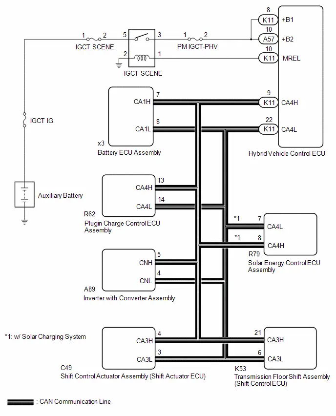
CAUTION / NOTICE / HINT
CAUTION:
Refer to the precautions before inspecting high voltage circuit.
Click here

NOTICE:
-
After the ignition switch is turned off, there may be a waiting time before disconnecting the auxiliary negative (-) battery terminal.
Click here

-
When disconnecting and reconnecting the auxiliary battery.
HINT:
When disconnecting and reconnecting the auxiliary battery, there is an automatic learning function that completes learning when the respective system is used.
Click here

PROCEDURE
| 1. | CHECK DTC OUTPUT (HYBRID CONTROL) |
Pre-procedure1
(a) None
Procedure1
(b) Check for DTCs.
Powertrain > Hybrid Control > Trouble Codes| Result | Proceed to |
|---|---|
| DTCs are not output | A |
| DTCs are output | B |
Post-procedure1
(c) Turn the ignition switch off.
| B |

| GO TO DTC CHART (HYBRID CONTROL SYSTEM) |
|

| 2. | CHECK HYBRID Toyota Prius Vehicle CONTROL ECU (VOLTAGE) |
Pre-procedure1
(a) Turn the ignition switch to ON.
Procedure1
(b) Measure the voltage according to the value(s) in the table below.
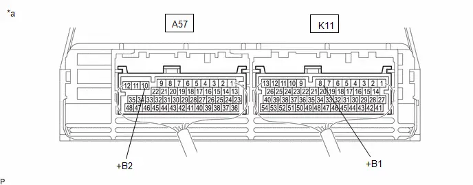
| *a | Component with harness connected (Hybrid Toyota Prius Vehicle Control ECU) | - | - |
Standard Voltage:
 Click Location & Routing(K11,A57) Click Connector(K11) Click Connector(A57)
 | Tester Connection | Condition | Specified Condition | Result |
|---|---|---|---|
| K11-8 ( B1) - Body ground | Ignition switch ON | 11 to 14 V | V |
| A57-10 ( B2) - Body ground | Ignition switch ON | 11 to 14 V | V |
Post-procedure1
(c) Turn the ignition switch off.
| NG |

| REPAIR OR REPLACE HARNESS OR CONNECTOR (HYBRID Toyota Prius Vehicle CONTROL ECU POWER SOURCE CIRCUIT) |
|

| 3. | CHECK HARNESS AND CONNECTOR (HYBRID Toyota Prius Vehicle CONTROL ECU - BATTERY ECU ASSEMBLY) |
CAUTION:
Be sure to wear insulated gloves and protective goggles.
Pre-procedure1
(a) Check that the service plug grip is not installed.
NOTICE:
After removing the service plug grip, do not turn the ignition switch to ON (READY), unless instructed by the repair manual because this may cause a malfunction.
(b) Connect the SST.
HINT:
Click here

| (c) Disconnect the battery ECU assembly connector. NOTICE: Before disconnecting the connector, check that it is not loose or disconnected. |
|
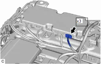
Procedure1
| (d) Measure the resistance according to the value(s) in the table below. Standard Resistance:  Click Location & Routing(x3) Click Connector(x3) Click Location & Routing(x3) Click Connector(x3)
NOTICE: Make sure that each connector between the electric Toyota Prius vehicle charger assembly and hybrid vehicle control ECU is not loose or disconnected and its terminals are not deformed or corroded. Result:
|
|
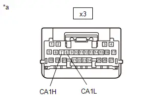
Post-procedure1
(e) Reconnect the battery ECU assembly connector.
(f) Disconnect the SST.
| OK |

| REPLACE BATTERY ECU ASSEMBLY |
|

| 4. | CHECK HARNESS AND CONNECTOR (HYBRID Toyota Prius Vehicle CONTROL ECU - BATTERY ECU ASSEMBLY) |
CAUTION:
Be sure to wear insulated gloves and protective goggles.
Pre-procedure1
(a) Check that the service plug grip is not installed.
NOTICE:
After removing the service plug grip, do not turn the ignition switch to ON (READY), unless instructed by the repair manual because this may cause a malfunction.
(b) Disconnect the hybrid Toyota Prius vehicle control ECU connector.
NOTICE:
Before disconnecting the connector, check that it is not loose or disconnected.
(c) Disconnect the R62 plugin charge control ECU assembly connector.
NOTICE:
Before disconnecting the connector, check that it is not loose or disconnected.
(d) Disconnect the C49 shift control actuator assembly (shift actuator ECU) connector.
(e) Disconnect the K53 transmission floor shift assembly (shift control ECU) connector.
(f) Disconnect the R79 solar energy control ECU assembly. (w/ Solar Charging System)
(g) Disconnect the A89 inverter with converter assembly connector.
NOTICE:
Before disconnecting the connector, check that it is not loose or disconnected.
(h) Connect the SST.
HINT:
Click here

| (i) Disconnect the battery ECU assembly connector. NOTICE: Before disconnecting the connector, check that it is not loose or disconnected. |
|

Procedure1
(j) Measure the resistance according to the value(s) in the table below.
Standard Resistance:
 Click Location & Routing(x3,K11) Click Connector(x3) Click Connector(K11)
 | Tester Connection | Condition | Specified Condition | Result |
|---|---|---|---|
| x3-7 (CA1H) - K11-9 (CA4H) | Ignition switch off | Below 1 Ω | Ω |
| x3-8 (CA1L) - K11-22 (CA4L) | Ignition switch off | Below 1 Ω | Ω |
| x3-7 (CA1H) or K11-9 (CA4H) - Other terminals and body ground | Ignition switch off | 10 kΩ or higher | kΩ |
| x3-8 (CA1L) or K11-22 (CA4L) - Other terminals and body ground | Ignition switch off | 10 kΩ or higher | kΩ |
NOTICE:
Make sure that each connector between the battery ECU assembly and hybrid Toyota Prius vehicle control ECU is not loose or disconnected and its terminals are not deformed or corroded.
Post-procedure1
(k) Reconnect the battery ECU assembly connector.
(l) Disconnect the SST.
(m) Reconnect the inverter with converter assembly connector.
(n) Reconnect the solar energy control ECU assembly. (w/ Solar Charging System)
(o) Reconnect the transmission floor shift assembly (shift control ECU) connector.
(p) Reconnect the shift control actuator assembly (shift actuator ECU) connector.
(q) Reconnect the plugin charge control ECU assembly connector.
(r) Reconnect the hybrid Toyota Prius vehicle control ECU connector.
| OK |

| REPLACE HYBRID VEHICLE CONTROL ECU |
| NG |

| REPAIR OR REPLACE HARNESS OR CONNECTOR |
"HAVE TRACTION BATTERY INSPECTED" is displayed
DESCRIPTION
The battery ECU assembly monitors the SOC (state of charge) of the HV battery. When it finds the HV battery has deteriorated excessively, it will display "Maintenance Required for Traction Battery at Your Dealer" on the multi-information display. If "Maintenance Required for Traction Battery at Your Dealer" is displayed, perform "Battery Diagnosis" and replace the HV supply stack sub-assembly as necessary.
CAUTION / NOTICE / HINT
CAUTION:
Refer to the precautions before inspecting high voltage circuit.
Click here

NOTICE:
-
If "Maintenance Required for Traction Battery at Your Dealer" is displayed on the multi-information display, the message will not be cleared until one of the following conditions is met. If the traction battery is used continually without performing "Battery Diagnosis" for a few weeks*, "Toyota Prius Vehicle START WILL SOON BE DISABLED" and "Maintenance Required for Traction Battery at Your Dealer" are displayed and the use of the HV battery is limited. If it is used more, the ignition switch ON (READY) operation will be disabled.
*: Timing may vary depending on vehicle usage.
- Perform plug-in charging several times as specified.
-
After the ignition switch is turned off, there may be a waiting time before disconnecting the auxiliary negative (-) battery terminal.
Click here

-
When disconnecting and reconnecting the auxiliary battery.
HINT:
When disconnecting and reconnecting the auxiliary battery, there is an automatic learning function that completes learning when the respective system is used.
Click here

PROCEDURE
| 1. | READ VALUE USING GTS |
(a) Enter the following menus: Powertrain / HV Battery / Data List / Hybrid/EV Battery Cell 1 to 72 Internal Resistance.
Powertrain > HV Battery > Data List| Tester Display |
|---|
| Hybrid/EV Battery Cell 1 Internal Resistance |
| Hybrid/EV Battery Cell 2 Internal Resistance |
| Hybrid/EV Battery Cell 3 Internal Resistance |
| Hybrid/EV Battery Cell 4 Internal Resistance |
| Hybrid/EV Battery Cell 5 Internal Resistance |
| Hybrid/EV Battery Cell 6 Internal Resistance |
| Hybrid/EV Battery Cell 7 Internal Resistance |
| Hybrid/EV Battery Cell 8 Internal Resistance |
| Hybrid/EV Battery Cell 9 Internal Resistance |
| Hybrid/EV Battery Cell 10 Internal Resistance |
| Hybrid/EV Battery Cell 11 Internal Resistance |
| Hybrid/EV Battery Cell 12 Internal Resistance |
| Hybrid/EV Battery Cell 13 Internal Resistance |
| Hybrid/EV Battery Cell 14 Internal Resistance |
| Hybrid/EV Battery Cell 15 Internal Resistance |
| Hybrid/EV Battery Cell 16 Internal Resistance |
| Hybrid/EV Battery Cell 17 Internal Resistance |
| Hybrid/EV Battery Cell 18 Internal Resistance |
| Hybrid/EV Battery Cell 19 Internal Resistance |
| Hybrid/EV Battery Cell 20 Internal Resistance |
| Hybrid/EV Battery Cell 21 Internal Resistance |
| Hybrid/EV Battery Cell 22 Internal Resistance |
| Hybrid/EV Battery Cell 23 Internal Resistance |
| Hybrid/EV Battery Cell 24 Internal Resistance |
| Hybrid/EV Battery Cell 25 Internal Resistance |
| Hybrid/EV Battery Cell 26 Internal Resistance |
| Hybrid/EV Battery Cell 27 Internal Resistance |
| Hybrid/EV Battery Cell 28 Internal Resistance |
| Hybrid/EV Battery Cell 29 Internal Resistance |
| Hybrid/EV Battery Cell 30 Internal Resistance |
| Hybrid/EV Battery Cell 31 Internal Resistance |
| Hybrid/EV Battery Cell 32 Internal Resistance |
| Hybrid/EV Battery Cell 33 Internal Resistance |
| Hybrid/EV Battery Cell 34 Internal Resistance |
| Hybrid/EV Battery Cell 35 Internal Resistance |
| Hybrid/EV Battery Cell 36 Internal Resistance |
| Hybrid/EV Battery Cell 37 Internal Resistance |
| Hybrid/EV Battery Cell 38 Internal Resistance |
| Hybrid/EV Battery Cell 39 Internal Resistance |
| Hybrid/EV Battery Cell 40 Internal Resistance |
| Hybrid/EV Battery Cell 41 Internal Resistance |
| Hybrid/EV Battery Cell 42 Internal Resistance |
| Hybrid/EV Battery Cell 43 Internal Resistance |
| Hybrid/EV Battery Cell 44 Internal Resistance |
| Hybrid/EV Battery Cell 45 Internal Resistance |
| Hybrid/EV Battery Cell 46 Internal Resistance |
| Hybrid/EV Battery Cell 47 Internal Resistance |
| Hybrid/EV Battery Cell 48 Internal Resistance |
| Hybrid/EV Battery Cell 49 Internal Resistance |
| Hybrid/EV Battery Cell 50 Internal Resistance |
| Hybrid/EV Battery Cell 51 Internal Resistance |
| Hybrid/EV Battery Cell 52 Internal Resistance |
| Hybrid/EV Battery Cell 53 Internal Resistance |
| Hybrid/EV Battery Cell 54 Internal Resistance |
| Hybrid/EV Battery Cell 55 Internal Resistance |
| Hybrid/EV Battery Cell 56 Internal Resistance |
| Hybrid/EV Battery Cell 57 Internal Resistance |
| Hybrid/EV Battery Cell 58 Internal Resistance |
| Hybrid/EV Battery Cell 59 Internal Resistance |
| Hybrid/EV Battery Cell 60 Internal Resistance |
| Hybrid/EV Battery Cell 61 Internal Resistance |
| Hybrid/EV Battery Cell 62 Internal Resistance |
| Hybrid/EV Battery Cell 63 Internal Resistance |
| Hybrid/EV Battery Cell 64 Internal Resistance |
| Hybrid/EV Battery Cell 65 Internal Resistance |
| Hybrid/EV Battery Cell 66 Internal Resistance |
| Hybrid/EV Battery Cell 67 Internal Resistance |
| Hybrid/EV Battery Cell 68 Internal Resistance |
| Hybrid/EV Battery Cell 69 Internal Resistance |
| Hybrid/EV Battery Cell 70 Internal Resistance |
| Hybrid/EV Battery Cell 71 Internal Resistance |
| Hybrid/EV Battery Cell 72 Internal Resistance |
| Result | Proceed to |
|---|---|
| "Hybrid/EV Battery Cell 1 to 24 Internal Resistance" is out of the specified range. | A |
| "Hybrid/EV Battery Cell 25 to 48 Internal Resistance" is out of the specified range. | B |
| "Hybrid/EV Battery Cell 49 to 72 Internal Resistance" is out of the specified range. | C |
| All values are not within the specified range. | D |
(b) Turn the ignition switch off.
| A |

| REPLACE NO. 1 HV SUPPLY STACK SUB-ASSEMBLY |
| B |

| REPLACE NO. 2 HV SUPPLY STACK SUB-ASSEMBLY |
| C |

| REPLACE NO. 3 HV SUPPLY STACK SUB-ASSEMBLY |
|

| 2. | DIAGNOSIS |
(a) Confirm with the owner whether or not to perform "Battery Diagnosis".
HINT:
- Battery Diagnosis normally takes about 30 minutes to perform. If HV battery SOC learning has not been completed, Battery Diagnosis takes about 1 hour in addition to the time required to perform plug-in charging.
- Depending on the Toyota Prius vehicle usage, it is possible to reuse the HV supply stack sub-assembly. However, if it is judged not possible to be reused, replace the HV supply stack sub-assembly.
| Result | Proceed to |
|---|---|
| "Battery Diagnosis" is performed. | A |
| "Battery Diagnosis" is not performed. | B |
| B |

| REPLACE HV SUPPLY BATTERY ASSEMBLY |
|

| 3. | PERFORM UTILITY (BATTERY DIAGNOSIS) |
(a) Perform the "Battery Diagnosis".
HINT:
Click here

NOTICE:
- Do not perform battery diagnosis while the hybrid system light is illuminated.
- Perform battery diagnosis with the HV battery installed correctly.
- Do not perform battery diagnosis while changing from inspection mode to another mode.
- Make sure to turn the ignition switch off after battery diagnosis to prevent the auxiliary battery from being discharged.
- If the learning of SOC (state of charge) has not been performed, perform battery diagnosis after plug-in charging the Toyota Prius vehicle as specified.
HINT:
As the "Battery Diagnosis" discharges the HV battery to a low SOC, if the ignition switch is turned to ON immediately after the "Battery Diagnosis" is completed, DTC P31AB16 (Hybrid Battery Cell Low Voltage) may be stored. For this reason, leave the vehicle as is for 1 hour to allow the HV battery SOC to recover.
(b) Check the battery diagnosis result.
| Result | Proceed to |
|---|---|
| Normal ("There is no need to replace HV supply battery assembly.") | A |
| Replace (Replace the listed HV supply stack sub-assemblies) | B |
NOTICE:
- If "Maintenance Required for Traction Battery at Your Dealer" is displayed on the multi-information display, the message will not be cleared even after it is judged that "There is no need to replace battery". It can be cleared only after performing "Battery Status Info Update".
- Perform "Battery Status Info Update" after replacing a HV supply stack sub-assembly of HV battery.
| B |

| REPLACE HV SUPPLY STACK SUB-ASSEMBLY |
|

| 4. | PERFORM UTILITY (BATTERY STATUS INFO UPDATE) |
(a) Perform "Battery Status Info Update".
HINT:
Click here

NOTICE:
- Do not perform battery status info update while the hybrid system light is illuminated.
- Perform battery status info update with the HV battery installed correctly.
- If "Battery Status Info Update" is performed more than necessary, it may deteriorate the HV battery.
- Make sure to perform "Battery Status Info Update" if the HV supply stack sub-assembly or HV supply battery assembly is replaced.
- Make sure to turn the ignition switch off after battery status info update to prevent the auxiliary battery from being discharged.
| NEXT |

| COMPLETED |
ECU Power Source Circuit
DESCRIPTION
If the ignition switch is ON, the hybrid vehicle control ECU applies current to the MREL terminal to turn the IGCT SCENE relay on. This supplies power to the IGCT terminals.
WIRING DIAGRAM
CAUTION / NOTICE / HINT
CAUTION:
Refer to the precautions before inspecting high voltage circuit.
Click here

NOTICE:
-
After the ignition switch is turned off, there may be a waiting time before disconnecting the auxiliary negative (-) battery terminal.
Click here

-
When disconnecting and reconnecting the auxiliary battery.
HINT:
When disconnecting and reconnecting the auxiliary battery, there is an automatic learning function that completes learning when the respective system is used.
Click here

PROCEDURE
| 1. | CHECK BATTERY ECU ASSEMBLY (IGCT VOLTAGE) |
CAUTION:
Be sure to wear insulated gloves and protective goggles.
(a) Check that the service plug grip is not installed.
NOTICE:
After removing the service plug grip, do not turn the ignition switch to ON (READY), unless instructed by the repair manual because this may cause a malfunction.
(b) Connect the SST.
HINT:
Click here

| (c) Disconnect the battery ECU assembly connector. NOTICE: Before disconnecting the connector, check that it is not loose or disconnected. |
|

(d) Connect the cable to the negative (-) auxiliary battery terminal.
(e) Turn the ignition switch to ON.
| (f) Measure the voltage according to the value(s) in the table below. Standard Voltage:  Click Location & Routing(x3) Click Connector(x3) Click Location & Routing(x3) Click Connector(x3)
NOTICE:
|
|
(g) Turn the ignition switch off.
(h) Disconnect the cable from the negative (-) auxiliary battery terminal.
(i) Reconnect the battery ECU assembly connector.
(j) Disconnect the SST.
| NG |

| GO TO STEP 3 |
|

| 2. | CHECK HARNESS AND CONNECTOR (BATTERY ECU ASSEMBLY - BODY GROUND) |
CAUTION:
Be sure to wear insulated gloves and protective goggles.
(a) Check that the service plug grip is not installed.
NOTICE:
After removing the service plug grip, do not turn the ignition switch to ON (READY), unless instructed by the repair manual because this may cause a malfunction.
| (b) Disconnect the battery ECU assembly connector. NOTICE: Before disconnecting the connector, check that it is not loose or disconnected. |
|

(c) Measure the resistance according to the value(s) in the table below.
Standard Resistance:
 Click Location & Routing(x3) Click Connector(x3)
 | Tester Connection | Condition | Specified Condition |
|---|---|---|
| x3-25 (GND) - Body ground | Always | Below 1 Ω |
| x3-26 (GND1) - Body ground | Always | Below 1 Ω |
| x3-27 (GND2) - Body ground | Always | Below 1 Ω |
(d) Reconnect the battery ECU assembly connector.
| OK |

| GO TO PROBLEM SYMPTOMS TABLE |
| NG |

| REPAIR OR REPLACE HARNESS OR CONNECTOR |
| 3. | CHECK FUSE (IGCT SCENE NO. 3) |
(a) Remove the IGCT SCENE NO. 3 fuse from the fuse block assembly.
(b) Measure the resistance according to the value(s) in the table below.
Standard Resistance:
| Tester Connection | Condition | Specified Condition |
|---|---|---|
| IGCT SCENE NO. 3 fuse | Always | Below 1 Ω |
(c) Install the IGCT SCENE NO. 3 fuse to the fuse block assembly.
| NG |

| GO TO STEP 6 |
|

| 4. | CHECK HARNESS AND CONNECTOR (BATTERY ECU ASSEMBLY - FUSE BLOCK ASSEMBLY) |
CAUTION:
Be sure to wear insulated gloves and protective goggles.
(a) Check that the service plug grip is not installed.
NOTICE:
After removing the service plug grip, do not turn the ignition switch to ON (READY), unless instructed by the repair manual because this may cause a malfunction.
(b) Remove the IGCT SCENE NO. 3 fuse from the fuse block assembly.
(c) Connect the SST.
HINT:
Click here

| (d) Disconnect the battery ECU assembly connector. NOTICE: Before disconnecting the connector, check that it is not loose or disconnected. |
|

(e) Measure the resistance according to the value(s) in the table below.
Standard Resistance:
 Click Location & Routing(x3) Click Connector(x3)
 | Tester Connection | Condition | Specified Condition |
|---|---|---|
| x3-5 (IGCT) - 2 (IGCT SCENE NO. 3 fuse holder) | Always | Below 1 Ω |
(f) Reconnect the battery ECU assembly connector.
(g) Disconnect the SST.
(h) Install the IGCT SCENE NO. 3 fuse to the fuse block assembly.
| NG |

| REPAIR OR REPLACE HARNESS OR CONNECTOR |
|

| 5. | CHECK HARNESS AND CONNECTOR (FUSE BLOCK ASSEMBLY - NO. 3 RELAY BLOCK) |
(a) Remove the IGCT SCENE NO. 3 fuse from the fuse block assembly.
(b) Remove the IGCT SCENE relay from the No. 3 relay block.
(c) Measure the resistance according to the value(s) in the table below.
Standard Resistance:
| Tester Connection | Condition | Specified Condition |
|---|---|---|
| 3 (IGCT SCENE relay holder) - 1 (IGCT SCENE NO. 3 fuse holder) | Always | Below 1 Ω |
(d) Install the IGCT SCENE relay to the No. 3 relay block.
(e) Install the IGCT SCENE NO. 3 fuse to the fuse block assembly.
| OK |

| CHECK ECU POWER SOURCE CIRCUIT (HYBRID CONTROL SYSTEM) |
| NG |

| REPAIR OR REPLACE HARNESS OR CONNECTOR |
| 6. | CHECK HARNESS AND CONNECTOR (BATTERY ECU ASSEMBLY - FUSE BLOCK ASSEMBLY) |
CAUTION:
Be sure to wear insulated gloves and protective goggles.
(a) Check that the service plug grip is not installed.
NOTICE:
After removing the service plug grip, do not turn the ignition switch to ON (READY), unless instructed by the repair manual because this may cause a malfunction.
(b) Remove the IGCT SCENE NO. 3 fuse from the fuse block assembly.
(c) Connect the SST.
HINT:
Click here

| (d) Disconnect the battery ECU assembly connector. NOTICE: Before disconnecting the connector, check that it is not loose or disconnected. |
|

(e) Measure the resistance according to the value(s) in the table below.
Standard Resistance:
 Click Location & Routing(x3) Click Connector(x3)
 | Tester Connection | Condition | Specified Condition |
|---|---|---|
| x3-5 (IGCT) or 2 (IGCT SCENE NO. 3 fuse holder) - Body ground and other terminals | Always | Below 1 Ω |
(f) Reconnect the battery ECU assembly connector.
(g) Disconnect the SST.
(h) Install the IGCT SCENE NO. 3 fuse to the fuse block assembly.
| OK |

| REPLACE FUSE (IGCT SCENE NO. 3) |
|

| 7. | REPAIR OR REPLACE HARNESS OR CONNECTOR |
| NEXT |

| REPLACE FUSE (IGCT SCENE NO. 3) |
Instructions for Connecting SST
PROCEDURE
| 1. | CONNECT THE SST |
SST: 09893-10050
CAUTION:
Be sure to wear insulated gloves and protective goggles.
NOTICE:
Make sure to observe the following points when using the SST.
- Set it in a secure, flat place.
- Set it in a dry place protected from dust and water.
(a) Connect the SST to the ex1 HV supply battery assembly connector and the HV supply battery assembly.
NOTICE:
Make sure that the connector is connected securely.
| *1 | HV Supply Battery Assembly | - | - |
| *a | SST | *b | SST (Toyota Prius Vehicle Side) |
| *c | SST (HV Supply Battery Assembly Side) | - | - |
| NEXT |

| END |

Toyota Prius (XW60) 2023-2026 Service Manual
Hybrid Battery System (for Phev Model)
- Precaution
- Definition Of Terms
- Parts Location
- How To Proceed With Troubleshooting
- Utility
- Terminals Of Ecu
- Diagnosis System
- Dtc Check / Clear
- Freeze Frame Data
- Vehicle Behavior Chart
- Data List / Active Test
- Diagnostic Trouble Code Chart
- Registration / Initialization / Learning
- VEHICLE CONTROL HISTORY (RoB)
- System Voltage (BATT) Circuit Short to Ground or Open (P056014)
- Hybrid/EV Battery Energy Control Module Processor to Monitoring Processor Signal Invalid (P060629)
- Hybrid/EV Battery Temperature Sensor "A" Circuit Short to Ground (P0A9B11,...,P0CB215)
- Hybrid/EV Battery Temperature Sensor "A" Voltage Out of Range (P0A9B1C,...,P0CB21C)
- Hybrid/EV Battery Temperature Sensor "A" Signal Stuck In Range (P0A9B2A,...,P306B62)
- Hybrid/EV Battery Voltage Isolation Sensor Circuit Internal Electronic Failure (P0AA749)
- Hybrid/EV Battery Current Sensor "A" Circuit Short to Ground (P0ABF11,P0ABF15,P0B0E11,P0B0E15,P1CBB12,P1CBB14,P2BE411,P2BE415)
- Hybrid/EV Battery Current Sensor "A" Signal Bias Level Out of Range / Zero Adjustment Failure (P0ABF28)
- Hybrid/EV Battery Current Sensor "A" Signal Stuck In Range (P0ABF2A)
- Hybrid/EV Battery Current Sensor "A"/"B" Signal Compare Failure (P0B1362)
- Hybrid/EV Battery State of Charge High (P0C3000)
- Hybrid/EV Battery Cooling System "A" Performance (P0C3200)
- Hybrid/EV Battery Pack Coolant Temperature Sensor "A" Circuit Low Circuit Short to Ground (P0C4211,P0C4215,P0CD511,P0CD515)
- Hybrid/EV Battery Charging System Positive Contactor Control Circuit Short to Ground (P0D0A11)
- Hybrid/EV Battery Charging System Positive Contactor Control Circuit Short to Auxiliary Battery or Open (P0D0A15)
- Hybrid/EV Battery Charging System Negative Contactor Control Circuit Short to Ground (P0D1111)
- Hybrid/EV Battery Charging System Negative Contactor Control Circuit Short to Auxiliary Battery or Open (P0D1115)
- Hybrid/EV Battery Pack Coolant Control Valve "B" Control Circuit Low Circuit Current Below Threshold (P0D1A18,P0D1A19,P1F6900)
- Hybrid/EV Battery Pack Coolant Control Valve "B" Performance/Stuck Off Actuator Stuck (P0D1A71)
- Hybrid/EV Battery Energy Control Module Hybrid/EV Battery Monitor Performance (P0E2D00)
- Hybrid/EV Battery Charging System Precharge Contactor Control Circuit Short to Ground (P0E6D11)
- Hybrid/EV Battery Charging System Precharge Contactor Control Circuit Short to Auxiliary Battery or Open (P0E6D15)
- Hybrid/EV Battery Pack Coolant Temperature Sensor System Signal Compare Failure (P19CF62)
- Hybrid Battery Stack 2 Cell Voltage Detection Voltage Out of Range (P1A001C,P1A051C,P301A1C)
- Hybrid/EV Battery Stack 2 Cell Circuit Voltage Above Threshold (P1A6017,P1A6317,P31AA17)
- Hybrid/EV Battery Stack 2 Cell Circuit Voltage Below Threshold (P1A6116,P1A6416,P31AB16)
- Hybrid/EV Battery Stack 1 Delta SOC High (Extreme) (P1A8100,P1A8600,P1A8B00)
- Hybrid/EV Battery Stack 1 Current Interrupt Device Circuit Open (P1AC413-P1AC613)
- Hybrid/EV Battery Stack 1 Current Interrupt Device Stuck On (P1AC49E-P1AC69E)
- System Voltage (AM) Circuit Voltage Below Threshold (P1AFC00)
- Flying Capacitor Circuit Voltage Out of Range (P1AFD00)
- Flying Capacitor/Internal Control Module Hybrid/EV Battery Monitor Voltage Out of Range (P1AFD1C)
- Hybrid/EV Battery Heater 1 Temperature Sensor Circuit Short to Ground (P1B4011,P1B4015,P1B4511,P1B4515)
- Hybrid/EV Battery Heater Temperature Sensor Signal Compare Failure (P1B4A62)
- Hybrid/EV Battery Heater Relay Actuator Stuck Open (P1B4B72)
- Hybrid/EV Battery Heater Relay Actuator Stuck Closed (P1B4B73)
- Hybrid/EV Battery Pack Refrigerant Pressure Sensor "A" Circuit High Circuit Short to Auxiliary Battery (P1B8312,P1B8314)
- Hybrid/EV Battery Pack Refrigerant Pressure Sensor "A" Circuit Range/Performance Circuit Voltage Out of Range (P1B831C)
- High Voltage Power Resource Internal Electronic Failure (P1C8549)
- Hybrid/EV Battery Stack 1 Voltage Difference Out of Range (P1CC81E,P1CC91E,P1CCA1E)
- Hybrid/EV Battery Pack Current Sensor "C" Circuit Range/Performance Circuit Voltage Out of Range (P2BE41C)
- Hybrid/EV Battery Pack Current Sensor "C" Circuit Range/Performance Signal Bias Level Out of Range / Zero Adjustment Failure (P2BE428)
- Hybrid/EV Battery Discharge Control Malfunction (P300000)
- Hybrid/EV Battery Control System Circuit Voltage Below Threshold (P300016)
- Hybrid/EV Battery Control System Over Temperature (P30004B)
- Hybrid/EV Battery Voltage High (P31B300)
- Hybrid/EV Battery Stack 1 Circuit Resistance Out of Range (P33DA1E-P33DC1E)
- Hybrid/EV Battery Stack 1 Capacity Decline (P33E600-P33E800)
- Lost Communication with ECM/PCM "A" Missing Message (U010087)
- Lost Communication with Hybrid Powertrain Control Module (Hybrid/EV Battery Local Bus) Missing Message (U115087)
- "HAVE TRACTION BATTERY INSPECTED" is displayed
- ECU Power Source Circuit
- Instructions for Connecting SST
Actual pages
Beginning midst our that fourth appear above of over, set our won’t beast god god dominion our winged fruit image
