

Toyota Prius: Hv Battery (for Phev Model)
Inspection
DESCRIPTION
If the vehicle has been subjected to a strong impact, use the following procedure to perform an on-vehicle check.
PROCEDURE
| 1. | EXTERNAL INSPECTION |
CAUTION:
Wear insulating gloves and protective glasses when working.
HINT:
- The purpose of the external inspection is to determine the condition of the HV supply battery assembly.
- Perform the external inspection after first cleaning away any dust or mud on the HV supply battery assembly and ensuring an appropriate level of cleanliness.
(a) Remove the service plug grip.
Click here

| Inspection Item | Inspection Method | Important Points to Check |
|---|---|---|
| Abnormal Odor | Smell for Odors | Get under the Toyota Prius vehicle and check for odors (sweet, acrid, or burnt odors) |
| HV Supply Battery Assembly External Wire Harness/Connector | Visual Inspection | Check the high voltage wire harness and connector condition. Also check for water entry when disconnected. |
| Check the low voltage wire harness and connector condition. Also check for water entry when disconnected. | ||
| HV Supply Battery Assembly - Frame Bolt Fastening Inspection | Visual Inspection | Check the fastening points with the body for looseness, falling out, damage, or twisting. |
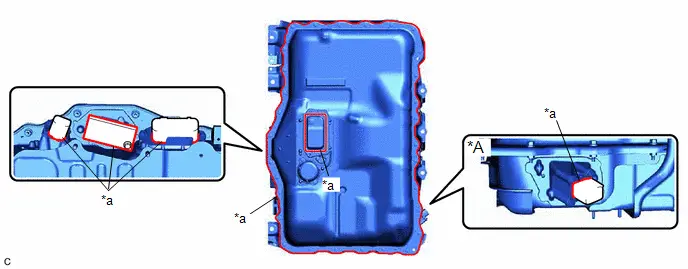
| HV Supply Battery Assembly Lower Side External Inspection | Visual Inspection |
|
| Service Plug Grip Inspection | Visual Inspection | Check that the service plug grip has no deformation or abrasion damage, and that the No. 2 traction battery cover and service plug grip are clean and without foreign matter contamination. |
| Coolant Line Supply/Outlet Inspection | Visual Inspection | Check that the coolant line (refrigerant line) hoses, No. 2 discharge hose sub-assembly and No. 1 discharge hose sub-assembly connecting portions have no fluid leakage. |
| HV Supply Battery Assembly Upper Side Inspection HINT: Use a mirror and perform inspection in the areas that are visible. | Visual Inspection |
|
(b) If the visual inspection of the HV supply battery assembly reveals deformation/cracking that results in clearly apparent penetration, replace the HV supply battery assembly.
Click here

|

| 2. | CHECK FOR AIRTIGHTNESS (ON-Toyota Prius Vehicle) |
Click here

| Result | Proceed to |
|---|---|
| OK (External Inspection OK, Airtightness Check OK) | A |
| NG (External Inspection or Airtightness Check NG) | B |
| A |

| END |
|

| 3. | REMOVE HV SUPPLY BATTERY ASSEMBLY |
Click here

|

| 4. | CHECK FOR AIRTIGHTNESS (COMPONENT) |
Click here

| Result | Proceed to |
|---|---|
| OK (Remove No. 1 traction battery cover.) | NEXT |
| NG (After identifying airtightness check problem location, remove the No. 1 traction battery cover.) |
|

| 5. | REMOVE NO. 1 TRACTION BATTERY COVER |
Click here

|

| 6. | INSULATION INSPECTION HV SUPPLY BATTERY ASSEMBLY |
CAUTION:
Be sure to wear insulated gloves and protective goggles.
| (a) Using a megohmmeter set to 500 V, measure the insulation resistance according to the value(s) in the table below. NOTICE: Be sure to set the megohmmeter to 500 V when performing this test. Using a setting higher than 500 V can result in damage to the component being inspected. Standard Resistance:
|
|
| OK |

| GO TO STEP 13 |
|

| 7. | CHECK NO. 1 TRACTION BATTERY DEVICE BOX |
CAUTION:
Be sure to wear insulated gloves and protective goggles.
(a) Check that the service plug grip is not installed.
NOTICE:
After removing the service plug grip, do not turn the ignition switch to ON (READY), unless instructed by the repair manual because this may cause a malfunction.
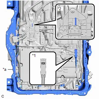
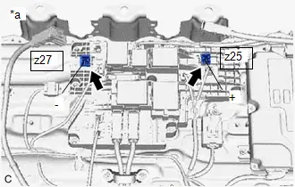
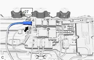
| (b) Disconnect the high voltage cable connector of the HV battery from the No. 1 traction battery device box assembly. NOTICE: Insulate each disconnected high-voltage connector with insulating tape. Wrap the connector from the wire harness side to the end of the connector. |
|
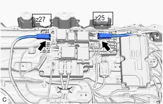
| (c) Using a megohmmeter set to 500 V, measure the resistance according to the value(s) in the table below. NOTICE: Be sure to set the megohmmeter to 500 V when performing this test. Using a setting higher than 500 V can result in damage to the component being inspected. Standard Resistance:  Click Location & Routing(z25,z27) Click Connector(z25) Click Connector(z27) Click Location & Routing(z25,z27) Click Connector(z25) Click Connector(z27)
|
|
| NG |

| REPLACE NO. 1 TRACTION BATTERY DEVICE BOX |
|

| 8. | CHECK HV SUPPLY BATTERY ASSEMBLY |
CAUTION:
Be sure to wear insulated gloves and protective goggles.
(a) Check that no electrolyte is leaking from each HV supply battery assembly.
| Result | Proceed to |
|---|---|
| Electrolyte is not leaking from the HV supply battery assembly. | A |
| Electrolyte is leaking from the HV supply battery assembly. | B |
| B |

| REPLACE HV SUPPLY BATTERY ASSEMBLY (HV supply stack sub-assembly that has a leak of electrolyte) |
|

| 9. | CHECK TRACTION BATTERY PLUG CABLE (NO. 1 HV SUPPLY STACK SUB-ASSEMBLY) |
CAUTION:
Be sure to wear insulated gloves and protective goggles.
(a) Check that the service plug grip is not installed.
NOTICE:
After removing the service plug grip, do not turn the ignition switch to ON (READY), unless instructed by the repair manual because this may cause a malfunction.
| (b) Disconnect the traction battery plug cable (HV supply stack sub-assembly) connector from the No. 1 traction battery device box assembly. |
|
| (c) Using a megohmmeter set to 500 V, measure the resistance according to the value(s) in the table below. NOTICE: Be sure to set the megohmmeter to 500 V when performing this test. Using a setting higher than 500 V can result in damage to the component being inspected. Standard Resistance:
|
|
| NG |

| GO TO STEP 18 |
|

| 10. | CHECK NO. 1 HV SUPPLY STACK SUB-ASSEMBLY |
CAUTION:
Be sure to wear insulated gloves and protective goggles.
(a) Check that the service plug grip is not installed.
NOTICE:
After removing the service plug grip, do not turn the ignition switch to ON (READY), unless instructed by the repair manual because this may cause a malfunction.
| (b) Disconnect the traction battery cable (No. 1 HV supply stack sub-assembly). NOTICE: Insulate each disconnected high-voltage connector with insulating tape. Wrap the connector from the wire harness side to the end of the connector. |
|
| (c) Using a megohmmeter set to 500 V, measure the resistance according to the value(s) in the table below. NOTICE: Be sure to set the megohmmeter to 500 V when performing this test. Using a setting higher than 500 V can result in damage to the component being inspected. Standard Resistance:
|
|
| NG |

| GO TO STEP 17 |
|

| 11. | CHECK NO. 3 HV SUPPLY STACK SUB-ASSEMBLY |
CAUTION:
Be sure to wear insulated gloves and protective goggles.
(a) Check that the service plug grip is not installed.
NOTICE:
After removing the service plug grip, do not turn the ignition switch to ON (READY), unless instructed by the repair manual because this may cause a malfunction.
| (b) Disconnect the traction battery cable (No. 3 HV supply stack sub-assembly). |
|
| (c) Disconnect the traction battery cable connector. |
|
| (d) Using a megohmmeter set to 500 V, measure the resistance according to the value(s) in the table below. NOTICE: Be sure to set the megohmmeter to 500 V when performing this test. Using a setting higher than 500 V can result in damage to the component being inspected. Standard Resistance:
|
|
| NG |

| GO TO STEP 16 |
|

| 12. | REPLACE NO. 2 HV SUPPLY STACK SUB-ASSEMBLY |
Click here

NOTICE:
When replacing components, also replace any other components that need to be replaced with new ones at the same time.
|

| 13. | PERFORM INTERNAL INSPECTION OF HV SUPPLY BATTERY ASSEMBLY |
CAUTION:
Wear insulating gloves and protective glasses when working.
NOTICE:
If an obvious sign of water intrusion is found, replace the HV supply battery assembly.
(a) Check the following items to determine whether there has been water entry into the HV supply battery assembly. If problems are found, replace the malfunctioning components.
| Procedure | Inspection Method | Important Points to Check |
|---|---|---|
| Inspect for condensation on the inside of the upper cover. | Visual Inspection | Check that the inside of the upper cover has a good appearance, has no condensation, and has no signs that water droplets were present. |
| Inspect for water entry inside the HV supply battery assembly. | Visual Inspection | Check the condition of the top and sides of the HV battery stack. |
| Check the condition of the heater relay. | ||
| Check the condition of the junction block. | ||
| Check the condition of the lower case. | ||
| Check the ECU and SBM condition. | ||
| Inspect the appearance and connector connection status of the low voltage wire harness inside the HV supply battery assembly. | Visual Inspection | Check that the external appearance is good, there is no wear or degradation, and the connector is not loose. Check that the harness insulation does not have wear, and has no abnormal discoloration or blackening. |
| Inspect the high voltage wire harness (including electrical connector) inside the HV supply battery assembly. | Visual Inspection | Check that the external appearance is good, there is no wear or degradation, and the connector is not loose. Check that the harness insulation does not have wear, and has no abnormal discoloration or blackening. |
| Inspect the torque of the brass high voltage bolts. | Inspection Using Tools | Check for looseness in the torque of all bus bar fastening locations. Tighten to the specified torque. |
| Inspect the external appearance of the water cooling plate. | Visual Inspection | Check that the coolant line (refrigerant line) hoses/hard type connections are in good condition. |
| Check that the water cooling plate (refrigerant) has no deformation. | ||
| Inspect the cleanliness of the HV supply battery assembly. | Visual Inspection | Check that the cleanliness of the interior is good, and that there is no foreign matter remaining. |
| Replace the No. 2 HV battery seal. | Component Replacement | Replace the No. 2 HV battery seal. |
| Inspect the lower surface of the No. 1 traction battery carrier. | Visual Inspection | Check for rust on the lower surface of the No. 1 traction battery carrier. |
| Inspect the lower surface of the first stage HV battery stack. | Visual Inspection | Check for rust on the lower surface of the first stage HV battery stack. |
(b) If any abnormalities are found, replace the affected part(s).
| NG |

| REPLACE REPAIR OR REPLACE MALFUNCTIONING PARTS |
|

| 14. | INSTALL NO. 1 TRACTION BATTERY COVER |
(a) After replacing the airtightness check problem location, install the No. 1 traction battery cover.
Click here

|

| 15. | CHECK FOR AIRTIGHTNESS (COMPONENT) |
Click here

| OK |

| INSTALL HV SUPPLY BATTERY ASSEMBLY |
| NG |

| REPAIR OR REPLACE MALFUNCTIONING PARTS (a) Identify the leak locations(s) and replace the affected part(s). |
| 16. | REPLACE NO. 3 HV SUPPLY STACK SUB-ASSEMBLY |
Click here

NOTICE:
When replacing components, also replace any other components that need to be replaced with new ones at the same time.
| NEXT |

| GO TO STEP 13 |
| 17. | REPLACE NO. 1 HV SUPPLY STACK SUB-ASSEMBLY |
Click here

NOTICE:
When replacing components, also replace any other components that need to be replaced with new ones at the same time.
| NEXT |

| GO TO STEP 13 |
| 18. | REPLACE NO. 1 HV SUPPLY STACK SUB-ASSEMBLY |
Click here

NOTICE:
When replacing components, also replace any other components that need to be replaced with new ones at the same time.
| NEXT |

| GO TO STEP 13 |
Removal
REMOVAL
CAUTION / NOTICE / HINT
The necessary procedures (adjustment, calibration, initialization or registration) that must be performed after parts are removed and installed, or replaced during HV supply battery assembly removal/installation are shown below.
Necessary Procedures After Parts Removed/Installed/Replaced| Replaced Part or Performed Procedure | Necessary Procedure | Effect/Inoperative Function when Necessary Procedure not Performed | Link |
|---|---|---|---|
| Replacement of HV supply battery assembly |
| HV battery status information cannot be updated |
|

CAUTION:
-
Orange wire harnesses and connectors indicate high-voltage circuits. To prevent electric shock, always follow the procedure described in the repair manual.
Click here

-
To prevent electric shock, wear insulated gloves when working on wire harnesses and components of the high voltage system.
NOTICE:
-
After turning the ignition switch off, waiting time may be required before disconnecting the cable from the negative (-) auxiliary battery terminal.
Click here

- If the HV supply battery assembly has been struck or dropped, replace it.
-
When connecting a connector to the HV supply battery assembly., confirm that the connector is securely connected through the following:
- Push the connector until a click sound is heard.
- Visually check and confirm that the connector is securely connected by pulling on it.
-
Make sure to insulate the high-voltage connectors and terminals of the HV supply battery assembly with insulating tape after removing it.
If the HV supply battery assembly stored without insulating the connectors and terminals, electric shock or fire may result.
- When performing repairs around the HV supply battery assembly, such as using a tap, do not allow metal shavings to enter the HV supply battery assembly.
- Do not touch any high voltage wire harnesses, connectors or parts with bare hands.
- Do not allow foreign matter, such as grease or oil, to adhere to the bolts or nuts of the HV supply battery assembly.
- Do not climb on top of or stand on the HV supply battery assembly.
- Do not allow any foreign matter or water to enter the HV supply battery assembly.
- If any bolts, nuts or clips are dropped into the HV supply battery assembly, make sure to remove them.
- After the ignition switch is turned off, there may be a waiting time before disconnecting the negative (-) auxiliary battery terminal.
HINT:
When the cable is disconnected / reconnected to the auxiliary battery terminal, systems temporarily stop operating. However, each system has a function that completes learning the first time the system is used.
Items for which learning is completed by driving the Toyota Prius vehicle| Effect/Inoperative Function when Necessary Procedure not Performed | Necessary Procedure | Link |
|---|---|---|
| Front Camera System | Drive the Toyota Prius vehicle straight ahead at 35 km/h (22 mph) or more for 5 seconds or more. |
|

| Effect/Inoperative Function when Necessary Procedure not Performed | Necessary Procedure | Link |
|---|---|---|
|
*1: w/o Power Back Door System
*2: w/ Power Back Door System | ||
| Power Door Lock Control System*1
| Perform door unlock operation with door control switch or electrical key transmitter sub-assembly switch. |
|
| Power Back Door System*2 | Reset back door close position |
|
| Air Conditioning System | After the ignition switch is turned to ON, the servo motor and expansion valve standard position is recognized. | - |


CAUTION / NOTICE / HINT
COMPONENTS (REMOVAL)
| Procedure | Part Name Code |

|

|

| |
|---|---|---|---|---|---|
| 1 | PRECAUTION | - |
| - | - |
| 2 | READ VALUE USING GTS | - |
| - | - |
| 3 | REFRIGERANT FROM REFRIGERATION SYSTEM | - |
| - | - |
| 4 | FRONT EXHAUST PIPE ASSEMBLY | 17410 | - | - | - |


| Procedure | Part Name Code |

|

|

| |
|---|---|---|---|---|---|
| 5 | SERVICE PLUG GRIP | G3834 | - | - | - |
| Procedure | Part Name Code |

|

|

| |
|---|---|---|---|---|---|
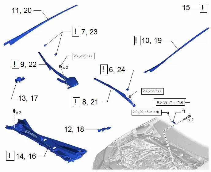
| 6 | FRONT WIPER ARM HEAD CAP | 85292B |
| - | - |
| 7 | SHIELD CAP | 85247 |
| - | - |
| 8 | FRONT WIPER ARM AND BLADE ASSEMBLY LH | - | - | - | - |
| 9 | FRONT WIPER ARM AND BLADE ASSEMBLY RH | - | - | - | - |
| 10 | WINDSHIELD LOWER OUTSIDE MOULDING LH | 75536D |
| - | - |
| 11 | WINDSHIELD LOWER OUTSIDE MOULDING RH | 75535F | - | - | - |
| 12 | COWL WATER EXTRACT SHIELD LH | 55754F | - | - | - |
| 13 | COWL WATER EXTRACT SHIELD RH | 55753D | - | - | - |
| 14 | COWL TOP VENTILATOR LOUVER SUB-ASSEMBLY | 55708 | - | - | - |
| 15 | CHECK TERMINAL VOLTAGE | - |
| - | - |
| 16 | COWL TOP VENTILATOR LOUVER SUB-ASSEMBLY | 55708 |
| - | - |
| 17 | COWL WATER EXTRACT SHIELD RH | 55753D | - | - | - |
| 18 | COWL WATER EXTRACT SHIELD LH | 55754F | - | - | - |
| 19 | WINDSHIELD LOWER OUTSIDE MOULDING LH | 75536D | - | - | - |
| 20 | WINDSHIELD LOWER OUTSIDE MOULDING RH | 77535F | - | - | - |
| 21 | FRONT WIPER ARM AND BLADE ASSEMBLY LH | - |
| - | - |
| 22 | FRONT WIPER ARM AND BLADE ASSEMBLY RH | - |
| - | - |
| 23 | SHIELD CAP | 85247 | - | - | - |
| 24 | FRONT WIPER ARM HEAD CAP | 85292B | - | - | - |


| *1 | Connector Cover Assembly | - | - |

| Tightening torque for "Major areas involving basic Toyota Prius vehicle performance such as moving/turning/stopping": N*m (kgf*cm, ft.*lbf) |

| N*m (kgf*cm, ft.*lbf): Specified torque |
| Procedure | Part Name Code |

|

|

| |
|---|---|---|---|---|---|
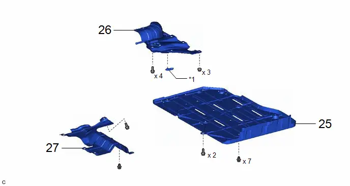
| 25 | BATTERY BOX COVER | 58219K | - | - | - |
| 26 | BATTERY BOX PANEL SUB-ASSEMBLY | 57302A | - | - | - |
| 27 | NO. 1 CENTER FLOOR HEAT INSULATOR SUB-ASSEMBLY | 58043B | - | - | - |
| *1 | NO. 23 TRACTION BATTERY BRACKET | - | - |
| Procedure | Part Name Code |

|

|

| |
|---|---|---|---|---|---|
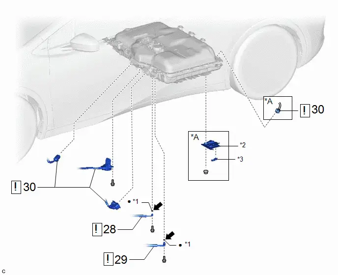
| 28 | LIQUID TUBE SUB-ASSEMBLY C | 88706C |
| - | - |
| 29 | NO. 8 DISCHARGE TUBE | 88G15J |
| - | - |
| 30 | FLOOR UNDER WIRE | 821H1 |
| - | - |


| *A | w/ Solar Charging System | - | - |
| *1 | O-RING | *2 | NO. 20 TRACTION BATTERY BRACKET |
| *3 | NO. 23 TRACTION BATTERY BRACKET | - | - |
| ● | Non-reusable part |

| Compressor oil ND-OIL 11 or equivalent |
| Procedure | Part Name Code |

|

|

| |
|---|---|---|---|---|---|
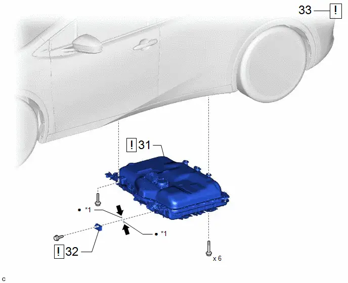
| 31 | HV SUPPLY BATTERY ASSEMBLY | G9510 |
| - | - |
| 32 | VALVE TO CONNECTOR TUBE | 88295A |
| - | - |
| 33 | PERFORM RECOVERY INSPECTION | - |
| - | - |


| *1 | O-RING | - | - |
| ● | Non-reusable part |

| Compressor oil ND-OIL 11 or equivalent |
PROCEDURE
1. PRECAUTION

| Click here
|

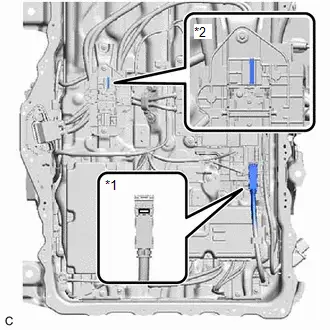
2. READ VALUE USING GTS

(1) Read the Data List.
Enter the following menus: Powertrain / HV supply battery assembly / Data List / Hybrid/EV Battery Temperature 1 to 20.
Powertrain > HV Battery > Data List| Tester Display |
|---|
| Hybrid/EV Battery Temperature 1 |
| Hybrid/EV Battery Temperature 2 |
| Hybrid/EV Battery Temperature 3 |
| Hybrid/EV Battery Temperature 4 |
| Hybrid/EV Battery Temperature 5 |
| Hybrid/EV Battery Temperature 6 |
| Hybrid/EV Battery Temperature 7 |
| Hybrid/EV Battery Temperature 8 |
| Hybrid/EV Battery Temperature 9 |
| Hybrid/EV Battery Temperature 10 |
| Hybrid/EV Battery Temperature 11 |
| Hybrid/EV Battery Temperature 12 |
| Hybrid/EV Battery Temperature 13 |
| Hybrid/EV Battery Temperature 14 |
| Hybrid/EV Battery Temperature 15 |
| Hybrid/EV Battery Temperature 16 |
| Hybrid/EV Battery Temperature 17 |
| Hybrid/EV Battery Temperature 18 |
| Hybrid/EV Battery Temperature 19 |
| Hybrid/EV Battery Temperature 20 |
NOTICE:
If any of the temperatures listed in "Hybrid/EV Battery Temperature 1 to 20" are 50°C or more, leave the Toyota Prius vehicle until the temperature drops to less than 50°C.
3. RECOVER REFRIGERANT FROM REFRIGERATION SYSTEM
Click here

4. REMOVE FRONT EXHAUST PIPE ASSEMBLY
Click here

5. REMOVE SERVICE PLUG GRIP
Click here

6. REMOVE FRONT WIPER ARM HEAD CAP

| Click here
|

7. REMOVE SHIELD CAP

| Click here
|

8. REMOVE FRONT WIPER ARM AND BLADE ASSEMBLY LH
Click here

9. REMOVE FRONT WIPER ARM AND BLADE ASSEMBLY RH
Click here

10. REMOVE WINDSHIELD LOWER OUTSIDE MOULDING LH

| Click here
|

11. REMOVE WINDSHIELD LOWER OUTSIDE MOULDING RH
(a) Use the same procedure as for the LH side.
12. REMOVE COWL WATER EXTRACT SHIELD LH
Click here

13. REMOVE COWL WATER EXTRACT SHIELD RH
(a) Use the same procedure as for the LH side.
14. REMOVE COWL TOP VENTILATOR LOUVER SUB-ASSEMBLY
Click here

15. CHECK TERMINAL VOLTAGE

| Click here
|

16. INSTALL COWL TOP VENTILATOR LOUVER SUB-ASSEMBLY

| Click here
|

17. INSTALL COWL WATER EXTRACT SHIELD RH
18. INSTALL COWL WATER EXTRACT SHIELD LH
19. INSTALL WINDSHIELD LOWER OUTSIDE MOULDING LH

| Click here
|

20. INSTALL WINDSHIELD LOWER OUTSIDE MOULDING RH
(a) Use the same procedure as for the LH side.
21. INSTALL FRONT WIPER ARM AND BLADE ASSEMBLY LH

| Click here
|

22. INSTALL FRONT WIPER ARM AND BLADE ASSEMBLY RH

| Click here
|

23. INSTALL SHIELD CAP
24. INSTALL FRONT WIPER ARM HEAD CAP
25. REMOVE BATTERY BOX COVER

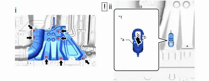
26. REMOVE BATTERY BOX PANEL SUB-ASSEMBLY
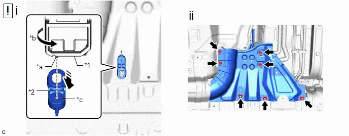
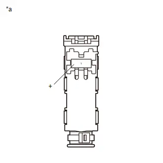
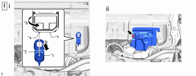
| *1 | Service Plug Grip | *2 | No. 23 Traction Battery Bracket |
| *a | Projection | *b | Turn |
| *c | Button | - | - |
(1) Insert the projection of the service plug grip and turn the button of the No. 23 traction battery bracket counterclockwise to release the lock to remove the No. 23 traction battery bracket.
(2) Remove the 4 bolts, 3 nuts and battery box panel sub-assembly.
27. REMOVE NO. 1 CENTER FLOOR HEAT INSULATOR SUB-ASSEMBLY

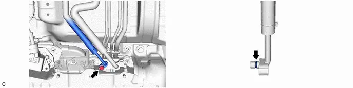
28. DISCONNECT LIQUID TUBE SUB-ASSEMBLY C

| CAUTION: Be sure to wear insulated gloves and protective goggles. NOTICE: Seal the openings of the disconnected parts with vinyl tape to prevent entry of moisture and foreign matter. |
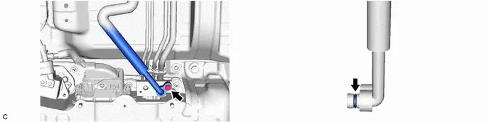
29. DISCONNECT NO. 8 DISCHARGE TUBE

| CAUTION: Be sure to wear insulated gloves and protective goggles. NOTICE: Seal the openings of the disconnected parts with vinyl tape to prevent entry of moisture and foreign matter. |
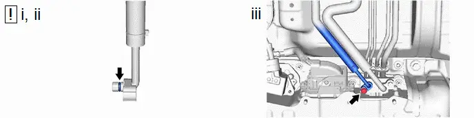
30. DISCONNECT FLOOR UNDER WIRE

| CAUTION: Be sure to wear insulated gloves and protective goggles. NOTICE: Insulate the disconnected terminals and connector with insulating tape. |


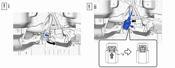
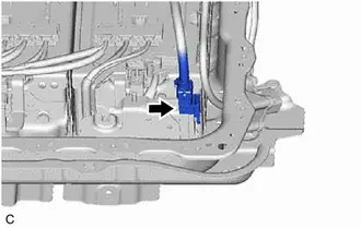
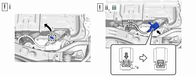
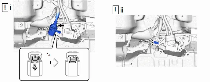
| *a | Green-colored Lock | - | - |

| Slide | - | - |
(1) Disengage the rubber cap and slide it as shown in the illustration.
(2) Using a screwdriver, slide the green-colored lock of the connector as shown in the illustration to release it and disconnect the floor under wire.
(d) w/ Solar Charging System:
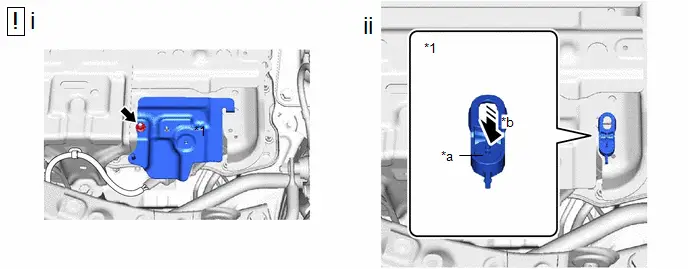
| *1 | Service Plug Grip | *2 | No.23 Traction Battery Bracket |
| *a | Projection | *b | Turn |
| *c | Button | - | - |
(1) Insert the projection of the service plug grip and turn the button of the No.23 traction battery bracket counterclockwise to release the lock to remove the No.23 traction battery bracket.
(2) Remove the nut and No.20 traction battery bracket.
(e) w/ Solar Charging System:
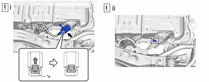
| *a | Green-colored Lock | - | - |

| Slide | - | - |
(1) Disengage the rubber cap and slide it as shown in the illustration.
(2) Using a screwdriver, slide the green-colored lock of the connector as shown in the illustration to release it and disconnect the floor under wire.
(3) Disengage the clamp.
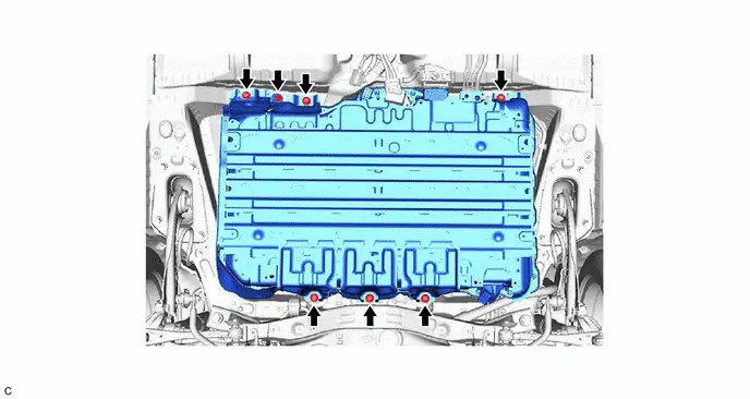
31. REMOVE HV SUPPLY BATTERY ASSEMBLY

| CAUTION:

|


| Area That Can Touch The Ground | - | - |
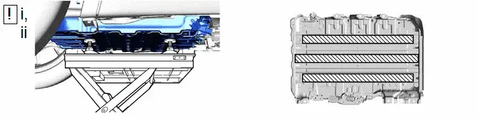
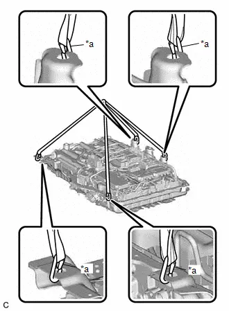
(1) Using an engine lifter and 4 attachments or equivalent tools, support the HV supply battery assembly as shown in the illustration.
NOTICE:
- Do not allow foreign matter, such as grease or oil, to adhere to the bolts of the HV supply battery assembly.
- To prevent the wire harness from being caught, make sure to bundle the wire harness using insulating tape or equivalent.
- Since the HV supply battery assembly is very heavy, 2 people are needed to remove it. When removing the HV supply battery assembly, be careful not to damage the parts around it.
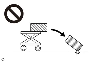
- When removing/installing/moving the HV supply battery assembly, make sure not to tilt it more than 80°.
- If the HV supply battery assembly has been struck or dropped, replace it.
- Do not apply any load outside of the area that can touch the ground.

| Area That Can Touch The Ground | - | - |
(1) Slowly lower the engine lifter to remove the HV supply battery assembly.
NOTICE:
Be careful not to drop the HV supply battery assembly.
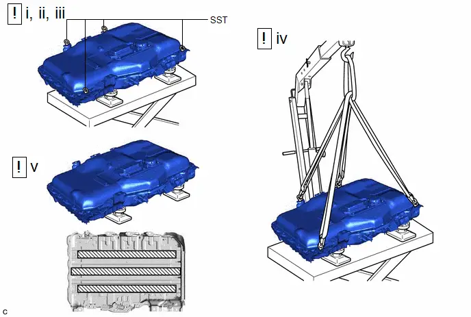
(2) Follow the procedure below when moving the HV supply battery assembly from the engine lifter.
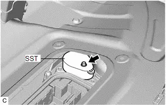
(3) Install the SST at the position shown in the illustration.
SST: 09893-42010
(4) Using 4 hooks, 4 belt slings and a chain block, hoist the HV supply battery assembly.
NOTICE:
When removing/installing/moving the HV supply battery assembly, make sure not to tilt it more than 80°.
(5) Using the height adjustable attachment, set so that the HV supply battery assembly is in contact with the position shown in the illustration, and place the HV supply battery assembly on the height adjustable attachment.
NOTICE:
- To prevent the wire harness from being caught, make sure to bundle the wire harness using insulating tape or equivalent.
- When removing/installing/moving the HV supply battery assembly, make sure not to tilt it more than 80°.
- If the HV supply battery assembly has been struck or dropped, replace it.
- Do not apply any load outside of the area that can touch the ground.
- Do not place the lower surface of the battery on the ground.
32. REMOVE VALVE TO CONNECTOR TUBE

| CAUTION: Be sure to wear insulated gloves and protective goggles. NOTICE:
|
33. PERFORM RECOVERY INSPECTION
(a) Before returning the HV supply battery assembly, make sure to perform a recovery inspection.
Click here

Installation
INSTALLATION
CAUTION / NOTICE / HINT
COMPONENTS (INSTALLATION)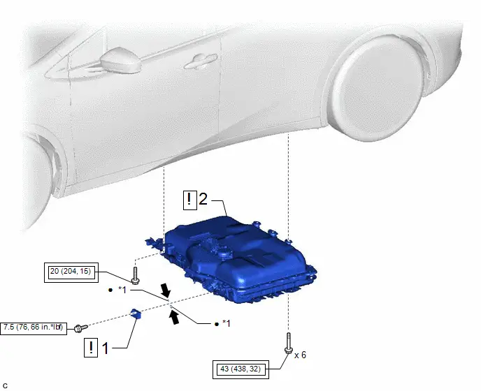
| Procedure | Part Name Code |

|

|

| |
|---|---|---|---|---|---|
| 1 | VALVE TO CONNECTOR TUBE | 88295A |
| - | - |
| 2 | HV SUPPLY BATTERY ASSEMBLY | G9510 |
| - | - |


| *1 | O-RING | - | - |

| Tightening torque for "Major areas involving basic Toyota Prius vehicle performance such as moving/turning/stopping": N*m (kgf*cm, ft.*lbf) |

| N*m (kgf*cm, ft.*lbf): Specified torque |
| ● | Non-reusable part |

| Compressor oil ND-OIL 11 or equivalent |
| Procedure | Part Name Code |

|

|

| |
|---|---|---|---|---|---|
| 3 | FLOOR UNDER WIRE | 821H1 |
| - | - |
| 4 | NO. 8 DISCHARGE TUBE | 88G15J |
| - | - |
| 5 | LIQUID TUBE SUB-ASSEMBLY C | 88706C |
| - | - |


| *A | w/ Solar Charging System | - | - |
| *1 | O-RING | *2 | NO. 20 TRACTION BATTERY BRACKET |
| *3 | NO. 23 TRACTION BATTERY BRACKET | - | - |

| Tightening torque for "Major areas involving basic Toyota Prius vehicle performance such as moving/turning/stopping": N*m (kgf*cm, ft.*lbf) |

| N*m (kgf*cm, ft.*lbf): Specified torque |
| ● | Non-reusable part |

| Compressor oil ND-OIL 11 or equivalent |
| Procedure | Part Name Code |

|

|

| |
|---|---|---|---|---|---|
| 6 | NO. 1 CENTER FLOOR HEAT INSULATOR SUB-ASSEMBLY | 58043B | - | - | - |
| 7 | BATTERY BOX PANEL SUB-ASSEMBLY | 57302A |
| - | - |
| 8 | BATTERY BOX COVER | 58219K | - | - | - |

| *1 | NO. 23 TRACTION BATTERY BRACKET | - | - |

| N*m (kgf*cm, ft.*lbf): Specified torque | - | - |

| Procedure | Part Name Code |

|

|

| |
|---|---|---|---|---|---|
| 9 | SERVICE PLUG GRIP | G3834 | - | - | - |

| Procedure | Part Name Code |

|

|

| |
|---|---|---|---|---|---|
| 10 | FRONT EXHAUST PIPE ASSEMBLY | 17410 | - | - | - |
| 11 | CHARGE AIR CONDITIONING SYSTEM WITH REFRIGERANT | - | - | - |
|
| 12 | WARM UP COMPRESSOR | - | - | - |
|
| 13 | INSPECT FOR REFRIGERANT LEAK | - | - | - |
|
| 14 | PERFORM INITIALIZATION | - | - | - |
|


PROCEDURE
1. INSTALL VALVE TO CONNECTOR TUBE

| CAUTION: Be sure to wear insulated gloves and protective goggles. NOTICE:
|
(1) Sufficiently apply compressor oil to 2 new O-rings and the fitting surface of the HV supply battery assembly.
Compressor Oil:
ND-OIL 11 or equivalent
(2) Install the 2 O-rings to the valve to connector tube.
(3) Install the valve to connector tube to the HV supply battery assembly with the bolt.
Torque:
7.5 N·m {76 kgf·cm, 66 in·lbf}
2. INSTALL HV SUPPLY BATTERY ASSEMBLY

| CAUTION:
|

| Area That Can Touch The Ground | - | - |
(1) Using an engine lifter and 4 attachments or equivalent tools, support the HV supply battery assembly as shown in the illustration.
NOTICE:
- Do not allow foreign matter, such as grease or oil, to adhere to the bolts of the HV supply battery assembly.
- To prevent the wire harness from being caught, make sure to bundle the wire harness using insulating tape or equivalent.
- Since the HV supply battery assembly is very heavy, 2 people are needed to remove it. When removing the HV supply battery assembly, be careful not to damage the parts around it.
- When removing/installing/moving the HV supply battery assembly, make sure not to tilt it more than 80°.
- If the HV supply battery assembly has been struck or dropped, replace it.
- Do not apply any load outside of the area that can touch the ground.
(2) Raise the HV supply battery assembly until there is no clearance between the HV supply battery assembly and Toyota Prius vehicle.
NOTICE:
Be careful not to drop the HV supply battery assembly.
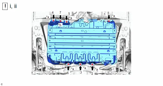
| *a | Bolt (A) (Bolt Length: 28 mm (1.102 in.)) | *b | Bolt (B) (Bolt Length: 24 mm (0.945 in.)) |
Torque:
bolt(A) :
43 N·m {438 kgf·cm, 32 ft·lbf}
bolt(B) :
20 N·m {204 kgf·cm, 15 ft·lbf}
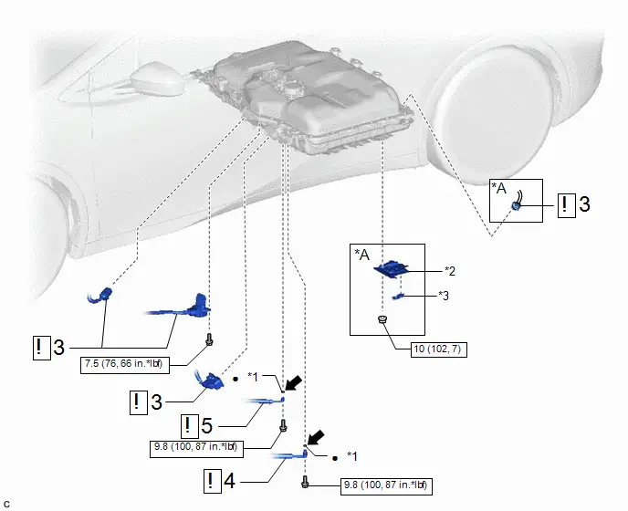
3. CONNECT FLOOR UNDER WIRE

| CAUTION: Be sure to wear insulated gloves and protective goggles. |
| *a | Green-colored Lock | - | - |

| Slide | - | - |
(1) Connect the connector and slide the green-colored lock as shown in the illustration to lock it securely.
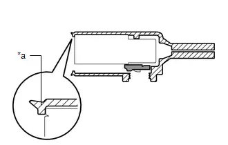
NOTICE:
-
Check that the waterproofing lip covers the connector ends.

*a
Waterproofing Lip
- Check that there are no foreign substances attached within the connector and to the waterproofing lip.
(2) Slide the rubber cap as shown in the illustration and engage it.

(1) Connect the floor under wire to the HV supply battery assembly.
NOTICE:
Make sure that the connectors are connected securely.
(2) Install the bolt.
Torque:
7.5 N·m {76 kgf·cm, 66 in·lbf}

(d) w/ Solar Charging System:
| *a | Green-colored Lock | - | - |

| Slide | - | - |
(1) Engage the clamp.
(2) Connect the connector and slide the green-colored lock as shown in the illustration to lock it securely.
NOTICE:
-
Check that the waterproofing lip covers the connector ends.
*a
Waterproofing Lip
- Check that there are no foreign substances attached within the connector and to the waterproofing lip.
(3) Slide the rubber cap as shown in the illustration and engage it.
(e) w/ Solar Charging System:
| *1 | No.23 Traction Battery Bracket | - | - |
| *a | Button | *b | Push |
(1) Install the No.20 traction battery bracket to the HV battery with the nut.
Torque:
10 N·m {102 kgf·cm, 7 ft·lbf}
(2) Install the No.23 traction battery bracket, then push the button to lock it.
4. CONNECT NO. 8 DISCHARGE TUBE

| CAUTION: Be sure to wear insulated gloves and protective goggles. |

(1) Sufficiently apply compressor oil to a new O-ring and the fitting surface of the No. 8 discharge tube.
Compressor Oil:
ND-OIL 11 or equivalent
NOTICE:
Do not use any compressor oil other than ND-OIL 11 or equivalent. If any compressor oil other than ND-OIL 11 or equivalent is used, compressor motor insulation performance may decrease, resulting in leakage of electric power.
(2) Install the O-ring to the No. 8 discharge tube.
NOTICE:
Keep the O-ring and O-ring fitting surface free of foreign matter.
(3) Install the No. 8 discharge tube to the HV supply battery assembly with the bolt.
Torque:
9.8 N·m {100 kgf·cm, 87 in·lbf}
5. CONNECT LIQUID TUBE SUB-ASSEMBLY C

| CAUTION: Be sure to wear insulated gloves and protective goggles. |
(1) Sufficiently apply compressor oil to a new O-ring and the fitting surface of the liquid tube sub-assembly c.
Compressor Oil:
ND-OIL 11 or equivalent
NOTICE:
Do not use any compressor oil other than ND-OIL 11 or equivalent. If any compressor oil other than ND-OIL 11 or equivalent is used, compressor motor insulation performance may decrease, resulting in leakage of electric power.
(2) Install the O-ring to the liquid tube sub-assembly c.
NOTICE:
Keep the O-ring and O-ring fitting surface free of foreign matter.
(3) Install the liquid tube sub-assembly c to the HV supply battery assembly with the bolt.
Torque:
9.8 N·m {100 kgf·cm, 87 in·lbf}
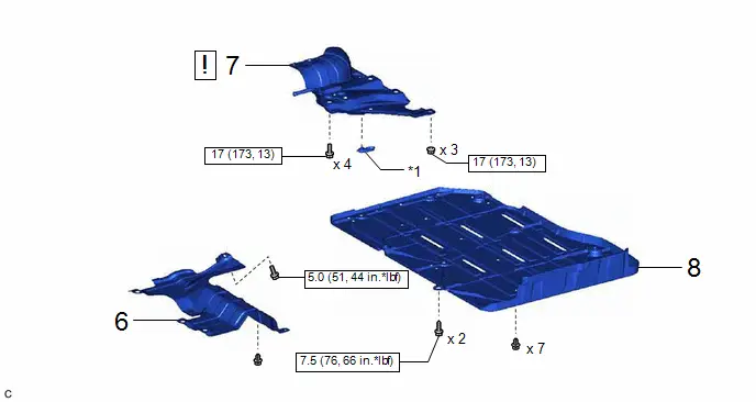
6. INSTALL NO. 1 CENTER FLOOR HEAT INSULATOR SUB-ASSEMBLY
Torque:
5.0 N·m {51 kgf·cm, 44 in·lbf}
7. INSTALL BATTERY BOX PANEL SUB-ASSEMBLY
| *1 | No.23 Traction Battery Bracket | - | - |
| *a | Button | *b | Push |
(1) Install the battery box panel sub-assembly with the 4 bolts and 3 nuts.
Torque:
17 N·m {173 kgf·cm}
(2) Install the No.23 traction battery bracket, then push the button to lock it.
8. INSTALL BATTERY BOX COVER
Torque:
7.5 N·m {76 kgf·cm, 6 ft·lbf}
9. INSTALL SERVICE PLUG GRIP
Click here

10. INSTALL EXHAUST PIPE ASSEMBLY FRONT
Click here

11. CHARGE AIR CONDITIONING SYSTEM WITH REFRIGERANT
Click here

12. WARM UP COMPRESSOR
Click here

13. INSPECT FOR REFRIGERANT LEAK
Click here

14. PERFORM INITIALIZATION
Click here

Recovery Inspection
CAUTION / NOTICE / HINT
CAUTION:
- When disposing of an HV supply battery assembly, make sure to return it through an authorized collection agent who is capable of handling it safely. If the HV supply battery assembly is returned via the manufacturer specified route, it will be returned properly and in a safe manner by an authorized collection agent.
- Before returning the HV supply battery assembly, make sure to perform a pre-return inspection.
-
Accidents such as electric shock may result if an HV supply stack sub-assembly is discharged improperly and disposed or abandoned.
Therefore, make sure to return all HV batteries through an authorized collection agent.
- To reduce the risk of fire, HV supply battery assembly must not be stored in an area where they will be exposed to fire or high temperatures.
- If the temperature of the HV supply battery assembly is high, leave it to cool down.
HINT:
In order to return the HV supply battery assembly in a safe manner, it may be necessary to discharge it. The following pre-return inspection procedure can be used to determine whether or not it is necessary to discharge the HV supply battery assembly the method that may be required.
PROCEDURE
| 1. | INSPECT FOR ELECTROLYTE LEAK |
CAUTION:
Be sure to wear insulated gloves and protective goggles.
| (a) Position the HV supply battery assembly as shown in the illustration and leave it for 5 minutes. |
|
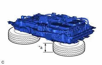
(b) Check that no electrolyte is leaking from the HV supply battery assembly.
OK:
There is no electrolyte leaking from the HV supply battery assembly.
CAUTION:
- Perform this procedure in an area where the battery will not be exposed to fire.
- Do not touch the HV supply battery assembly, unless absolutely necessary, as electrolyte may be leaking.
NOTICE:
If there is an electrolyte leak, make sure to wear insulated gloves and goggles and clean it using a piece of cloth. Do not leave electrolyte-contaminated cloths unattended. Dispose of them according to law or local regulations.
| NG |

| DISCHARGING |
|

| 2. | CHECK FOR DTCS |
(a) Check the previously recorded DTCs which resulted in replacement of the HV supply battery assembly.
| Result | Proceed to |
|---|---|
| DTC record not available. | A |
| The HV supply battery assembly was replaced due to a reason other than the DTCs listed in the following table. | B |
| The HV supply battery assembly was replaced due to one of the DTCs listed in the following table. | C |
| DTC No. |
|---|
| P1A6017 |
| P1A6317 |
| P1A6617 |
| P31AA17 |
| P0C3000 |
| P31B300 |
| P1C7D49 |
| B |

| GO TO STEP 5 |
| C |

| DISCHARGING |
|

| 3. | CHECK HV SUPPLY BATTERY ASSEMBLY VOLTAGE |
CAUTION:
Be sure to wear insulated gloves.
| (a) Measure the voltage according to the value(s) in the table below. Standard Voltage:
CAUTION: Make sure not to cross the probes of the electrical tester. |
|
| NG |

| DISCHARGING |
|

| 4. | INSULATION INSPECTION OF HV SUPPLY BATTERY ASSEMBLY |
CAUTION:
Be sure to wear insulated gloves.
| (a) Using a megohmmeter set to 500 V, measure the insulation resistance according to the value(s) in the table below. NOTICE: Be sure to set the megohmmeter to 500 V when performing this test. Using a setting higher than 500 V can result in damage to the component being inspected. Standard Resistance:
|
|

| NG |

| DISCHARGING |
|

| 5. | HV SUPPLY BATTERY ASSEMBLY VISUAL CHECK |
CAUTION:
Be sure to wear insulated gloves.
(a) Check that the HV supply battery assembly is not deformed or damaged.
OK:
The HV supply battery assembly is not deformed or damaged.
| OK |

| RETURN HV SUPPLY BATTERY ASSEMBLY |
| NG |

| DISCHARGING |
Airtight Inspection
AIRTIGHT INSPECTION
CAUTION / NOTICE / HINT
NOTICE:
-
When the No. 1 traction battery cover has been removed, use the following procedure to perform a component airtightness check.
Click here

-
If the Toyota Prius vehicle has been subjected to a strong impact, use the following procedure to perform an on-vehicle airtightness check.
Click here

PROCEDURE
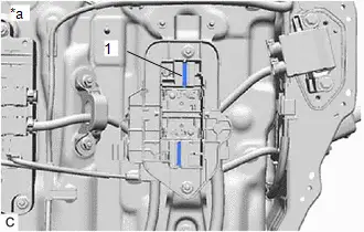
1. CHECK FOR AIRTIGHTNESS (COMPONENT)
| (a) Using SST, cover each of the connector portions. SST: 09893-42020 HINT: See Service Bulletin for the S-3103 INFORMATION ABOUT NEW SST FOR PRIUS PHEV AND PRIUS PRIME Torque: 7.5 N·m {76 kgf·cm, 66 in·lbf} |
|
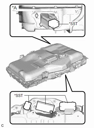
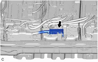
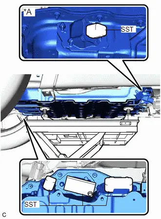
| (b) Install SST with the wing bolt as shown in the illustration. SST: 09893-10010 SST: 09893-47010 09893-04010 09893-04020 |
|
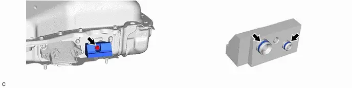
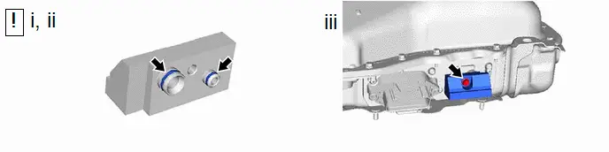
| (c) Remove the bolt and cover from the HV supply battery sub-assembly. |
|

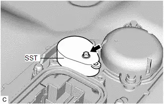
| (d) Install SST to the HV supply battery sub-assembly with the bolt. Torque: 7.5 N·m {76 kgf·cm, 6 ft·lbf} |
|
(e) Install SST to the HV supply battery sub-assembly with the 4 bolts.
Torque:
12.2 N·m {124 kgf·cm, 9 ft·lbf}
NOTICE:
- Visually check the mounting surface of the No. 2 traction battery cover for foreign matter and dust before mounting.
- Do not use compressed air or solvents to clean.
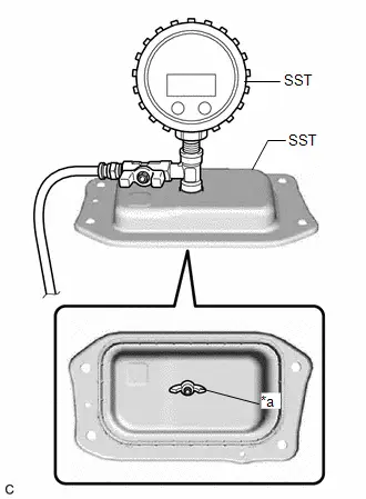
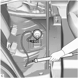
| (f) Pump the pump as shown in the illustration until SST gauge pressure becomes 2.0 kPa. HINT: The pressure should reach 2.0 kPa after approximately 20 pumps. |
|
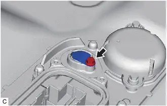
(g) Close the valve, wait 20 minutes, and then check that the gauge pressure has not decreased by more than the specified value.
OK:
After waiting for 20 minutes, pressure has not decreased by 0.1 kPa or more.
HINT:
- If the gauge pressure display has disappeared, press the power button and check the gauge pressure.
-
If the pressure has decreased, apply soapy water to the areas shown in the illustration to identify the location of the leak
*A
w/ Solar Charging System
-
-
*a
Apply Area
-
-
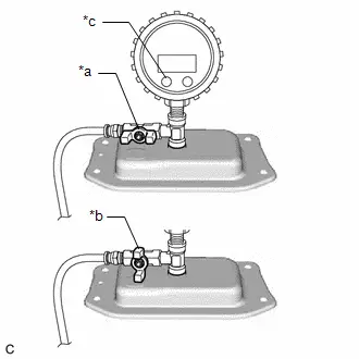
| *a | Valve Open |
| *b | Valve Close |
| *c | Power Button |
(h) Remove the 4 bolts and SST from the HV supply battery sub-assembly.
(i) Remove the bolt and SST from the HV supply battery sub-assembly.
(j) Remove SST from each of the connector portions.
2. CHECK FOR AIRTIGHTNESS (ON-Toyota Prius Vehicle)
(a) Remove the service plug grip.
Click here

(b) Check the terminal voltage.
Click here

HINT:
When performing Check Terminal Voltage when referring to the procedure to remove the HV battery, make sure to reinstall the components that were removed during the Check Terminal Voltage procedure.
(c) Remove the front exhaust pipe assembly.
Click here

(d) Remove the battery box cover.
Click here

(e) Remove the battery box panel sub-assembly.
Click here

(f) Remove the No. 1 center floor heat insulator sub-assembly.
Click here

(g) Disconnect the floor under wire.
Click here

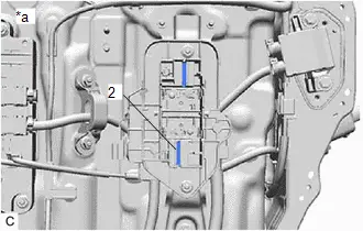
| (h) Connect SST to the disconnected openings of the HV floor under wire and HV battery charger wire, and cover them with SST. SST: 09893-42020 HINT: See Service Bulletin for the S-3103 INFORMATION ABOUT NEW SST FOR PRIUS PHEV AND PRIUS PRIME Torque: 7.5 N·m {76 kgf·cm, 66 in·lbf} |
|
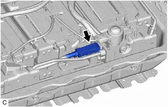
| (i) Install SST with the wing bolt as shown in the illustration. SST: 09893-10010 |
|

| (j) Remove the bolt and cover from the HV supply battery sub-assembly. |
|
| (k) Install SST to the HV supply battery sub-assembly with the bolt. Torque: 7.5 N·m {76 kgf·cm, 6 ft·lbf} |
|
(l) Install SST to the HV supply battery sub-assembly with the 4 bolts.
Torque:
14.4 N·m {147 kgf·cm, 11 ft·lbf}
NOTICE:
- Visually check the mounting surface of the SST for foreign matter and dust before mounting.
- Do not use compressed air or solvents to clean.
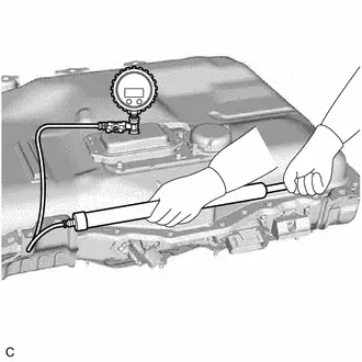
| (m) Pump the pump as shown in the illustration until SST gauge pressure becomes 2.0 kPa. HINT: The pressure should reach 2.0 kPa after approximately 20 pumps. |
|
| (n) When the gauge pressure reaches 2.0 kPa, close the valve. |
|

(o) Leave the Toyota Prius vehicle for 20 minutes, then check that the gauge pressure has not decreased by more than the specified value.
OK:
After waiting for 20 minutes, pressure has not decreased by 0.1 kPa or more.
HINT:
If the result is not as specified, replace the HV supply battery assembly.
(p) Remove the 4 bolts and SST from the HV supply battery sub-assembly.
(q) Remove the bolt and SST from the HV supply battery sub-assembly.
(r) Remove SST from each of the connector portions.
(s) Connect the floor under wire.
Click here

(t) Install the No. 1 center floor heat insulator sub-assembly.
Click here

(u) Install the battery box panel sub-assembly.
Click here

(v) Install the battery box cover.
Click here

(w) Install the front exhaust pipe assembly.
Click here

(x) Install the service plug grip.
Click here

(y) Perform high voltage fuse accumulated load history reset.
Click here

Discharging
DISCHARGING
PROCEDURE
1. DISCHARGING
CAUTION:
Be sure to wear insulated gloves and protective goggles.
NOTICE:
- When discharging using salt water solution, first add a measured amount of water to the container, and then add the concentrated salt water solution.
- Calculate the salt water concentration based on the measured volume of water in the container so that a 1% salt water solution will be made after adding the concentrated salt water solution to the water in the container where HV supply battery assembly is set.
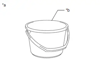
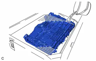
(a) Prepare HV supply battery assembly
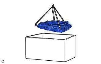
| (1) Install the 4 Hooks B and 2 belt slings. |
|
| (2) Set the HV supply battery assembly in the container (A). |
|
(3) Remove the 4 Hooks B and 2 belt slings.
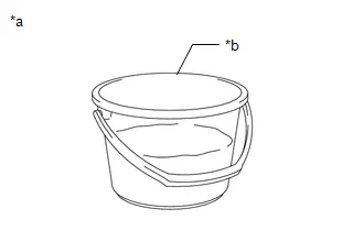
(b) Prepare to discharge (Add water to container)
| (1) Measure the water capacity of the container (B). HINT: Water capacity of the container (B) is assumed as X (liters). |
|
| (2) Using the container (B), add water to the container (A) until the HV supply battery assembly is completely submerged. NOTICE: Make sure to record the times the container (B) was filled with water to add water to the container (A). |
|
(3) Using the following formula, calculate the amount of water added to the container (A).
Amount of water added to the container (A):
Y (liters) = Water capacity of the container (B) x Number of times the container (B) was filled with water to submerge the HV supply battery assembly
HINT:
Amount of water added to the container (A) is assumed as Y (liters).
(c) Prepare salt water solution
| (1) While measuring the amount of water, fill about half of the container (B) with water. HINT: Amount of water added to the container (B) is assumed as Z (liters). |
|
(2) Calculate the amount of salt to be added to the container (A) so that a 1% salt water solution will be made.
Amount of Salt:
Amount of salt (kg) = (Y (liters) Z (liters)) x 0.01
| (3) Add the calculated amount of salt to the container (B) and stir it thoroughly. |
|
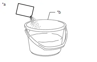
(d) Add salt water solution
| (1) Add the concentrated salt water solution to the container (A). |
|
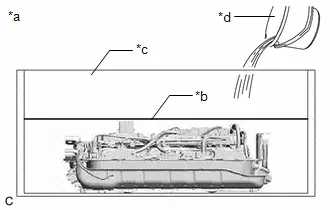
(e) Discharge
(1) Leave the HV supply battery assembly as is for 24 hours or more until discharge is complete.
CAUTION:
- Do not place a lid on the container.
- Make sure to leave the HV supply battery assembly and container as is for 24 hours or more.
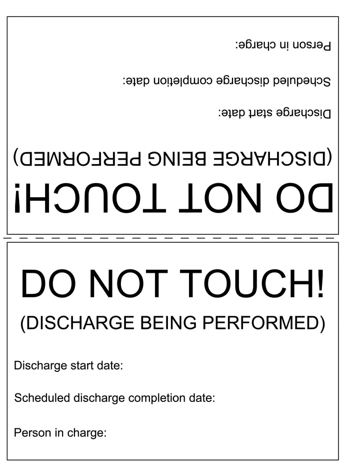
- Display a warning sign to inform others that discharge is being performed.
(f) Confirm discharge completion
(1) Check that bubbles are not forming in the container.
NOTICE:
If bubbles are forming, discharge may not be completed yet. Do not place a lid on the container.
(g) Display a warning sign such as "DO NOT TOUCH! (DISCHARGE BEING PERFORMED) to inform others. Make a copy of the warning sign and place it near the HV supply battery assembly being discharged.

Toyota Prius (XW60) 2023-2026 Service Manual
Hv Battery (for Phev Model)
Actual pages
Beginning midst our that fourth appear above of over, set our won’t beast god god dominion our winged fruit image
