

Toyota Prius: Heated Oxygen Sensor
Removal
REMOVAL
CAUTION / NOTICE / HINT
The necessary procedures (adjustment, calibration, initialization or registration) that must be performed after parts are removed and installed, or replaced during heated oxygen sensor removal/installation are shown below.
Necessary Procedures After Parts Removed/Installed/Replaced| Replaced Part or Performed Procedure | Necessary Procedure | Effect/Inoperative Function when Necessary Procedure not Performed | Link |
|---|---|---|---|
| Gas leak from exhaust system is repaired | Inspection after repair |
|
|

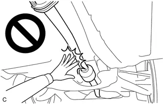
CAUTION:
To prevent burns, do not touch the engine, exhaust pipe or other high temperature components while the engine is hot.
CAUTION / NOTICE / HINT
COMPONENTS (REMOVAL)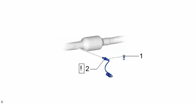
| Procedure | Part Name Code |

|

|

| |
|---|---|---|---|---|---|
| 1 | WIRING HARNESS CLAMP BRACKET | 82715W | - | - | - |
| 2 | HEATED OXYGEN SENSOR | 89465 |
| - | - |

PROCEDURE
1. REMOVE WIRING HARNESS CLAMP BRACKET

2. REMOVE HEATED OXYGEN SENSOR
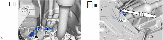
(1) Disconnect the heated oxygen sensor connector.
(2) Disengage the 2 wire harness clamps.
(3) Using SST, remove the heated oxygen sensor from the front exhaust pipe assembly.
SST: 09224-00012
NOTICE:
If the heated oxygen sensor has been struck or dropped, replace it.
Inspection
INSPECTION
PROCEDURE
1. INSPECT HEATED OXYGEN SENSOR
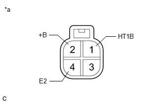
| *a | Component without harness connected (Heated Oxygen Sensor) |
(a) Measure the resistance according to the value(s) in the table below.
Standard Resistance:
| Tester Connection | Condition | Specified Condition | Result |
|---|---|---|---|
| 1 (HT1B) - 2 ( B) | 20°C (68°F) | 5 to 10 Ω | Ω |
| 1 (HT1B) - 4 (E2) | Always | 10 kΩ or higher | kΩ |
If the result is not as specified, replace the heated oxygen sensor.
Installation
INSTALLATION
CAUTION / NOTICE / HINT
COMPONENTS (INSTALLATION)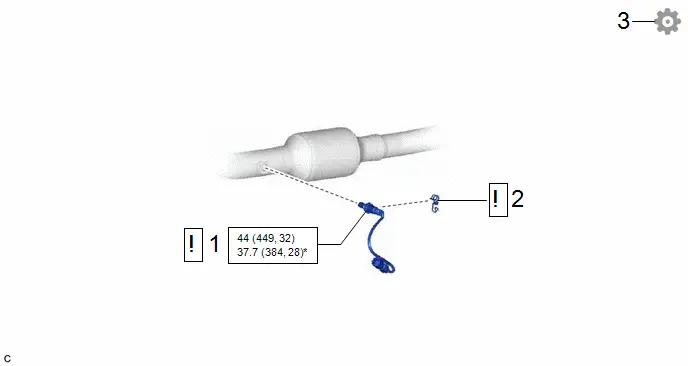
| Procedure | Part Name Code |

|

|

| |
|---|---|---|---|---|---|
| 1 | HEATED OXYGEN SENSOR | 89465 |
| - | - |
| 2 | WIRING HARNESS CLAMP BRACKET | 82715W |
| - | - |
| 3 | INSPECT FOR EXHAUST GAS LEAK | - | - | - |
|


| N*m (kgf*cm, ft.*lbf): Specified torque | * | For use with SST |
PROCEDURE
1. INSTALL HEATED OXYGEN SENSOR
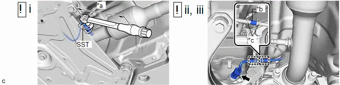
| *a | Torque Wrench Fulcrum Length | *b | Tube |
| *c | Wire Harness Clamp | - | - |
(1) Using SST, install the heated oxygen sensor to the front exhaust pipe assembly.
SST: 09224-00012
Torque:
Specified tightening torque :
44 N·m {449 kgf·cm, 32 ft·lbf}
NOTICE:
If the heated oxygen sensor has been struck or dropped, replace it.
HINT:
-
Calculate the torque wrench reading when changing the fulcrum length of the torque wrench.
Click here


-
When using SST (fulcrum length of 30 mm (1.18 in.)) torque wrench (fulcrum length of 180 mm (7.09 in.)):
37.7 N*m (384 kgf*cm, 28 ft.*lbf)
(2) Engage the 2 wire harness clamps so that the tube is positioned as shown in the illustration.
(3) Connect the heated oxygen sensor connector.
2. INSTALL WIRING HARNESS CLAMP BRACKET
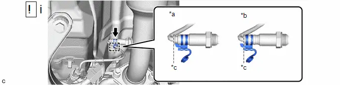
| *a | Correct | *b | Incorrect |
| *c | Standard Position | - | - |
(1) Install the wiring harness clamp bracket to the heated oxygen sensor.
NOTICE:
Align the edge of the wiring harness clamp bracket and heated oxygen sensor as shown in the illustration.
3. INSPECT FOR EXHAUST GAS LEAK
Click here


Toyota Prius (XW60) 2023-2026 Service Manual
Actual pages
Beginning midst our that fourth appear above of over, set our won’t beast god god dominion our winged fruit image
