

Toyota Prius: Front Bumper
Removal
REMOVAL
CAUTION / NOTICE / HINT
The necessary procedures (adjustment, calibration, initialization or registration) that must be performed after parts are removed and installed, or replaced during front bumper assembly removal/installation are shown below.
Necessary Procedures After Parts Removed/Installed/Replaced| Replaced Part or Performed Procedure | Necessary Procedures | Effect/Inoperative Function When Necessary Procedures are not Performed | Link |
|---|---|---|---|
| *: Even when not replacing the part, it is necessary to perform the specified necessary procedures after installation. | |||
| Front television camera view adjustment | Panoramic View Monitor System |
|
| Advanced Park |
| ||
| Replacement or removal and installation of 2 or more parts:
| Television camera view adjustment | Panoramic View Monitor System |
|


CAUTION / NOTICE / HINT
HINT:
-
When the front bumper is damaged or deformed due to an accident or contact with other objects, etc., or the bumper installation area on the body is repaired, it is necessary to perform millimeter wave radar sensor adjustment.
-
TARGET ADJUSTMENT (TRIANGLE TARGET):
Click here

-
TARGET ADJUSTMENT (FLAT SURFACE TARGET):
Click here

-
DRIVING ADJUSTMENT:
Click here

-
TARGET ADJUSTMENT (TRIANGLE TARGET):
-
When the front bumper is damaged or deformed due to an accident or contact with other objects, etc., or the bumper installation area on the body is repaired, it is necessary to perform ultrasonic sensor detection angle measurement.
-
w/ Parking Support Brake System:
Click here

-
w/ Advanced Park:
Click here

-
w/ Parking Support Brake System:
- If the front bumper is damaged or deformed due to an accident, contact, etc., and repairs have been made to the area of the body to which the headlight assembly is installed, it is necessary to perform front side radar sensor adjustment.
-
If a problem is found during the visual inspection, check the installation condition of the front side radar sensor, and adjust the installation position of the front side radar sensor as necessary.
-
TARGET ADJUSTMENT (TRIANGLE TARGET):
Click here

-
DRIVING ADJUSTMENT:
Click here

-
TARGET ADJUSTMENT (TRIANGLE TARGET):
CAUTION / NOTICE / HINT
COMPONENTS (REMOVAL)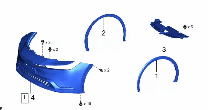
| Procedure | Part Name Code |

|

|

| |
|---|---|---|---|---|---|
| 1 | FRONT FENDER MOULDING SUB-ASSEMBLY LH | 75602A | - | - | - |
| 2 | FRONT FENDER MOULDING SUB-ASSEMBLY RH | 75601A | - | - | - |
| 3 | RADIATOR SUPPORT OPENING COVER | 53289A | - | - | - |
| 4 | FRONT BUMPER ASSEMBLY | - |
| - | - |

PROCEDURE
1. REMOVE FRONT FENDER MOULDING SUB-ASSEMBLY LH
Click here

2. REMOVE FRONT FENDER MOULDING SUB-ASSEMBLY RH
(a) Use the same procedure as for the LH side.
3. REMOVE RADIATOR SUPPORT OPENING COVER
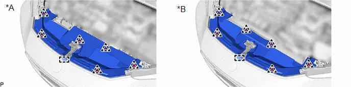
| *A | for 2ZR-FXE | *B | for M20A-FXS |
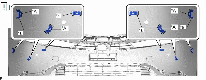
4. REMOVE FRONT BUMPER ASSEMBLY
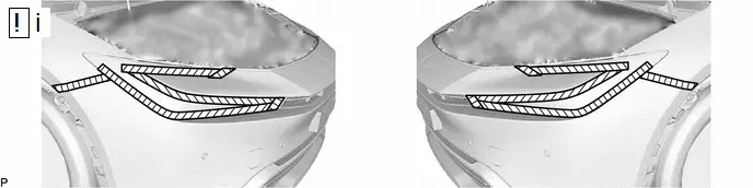
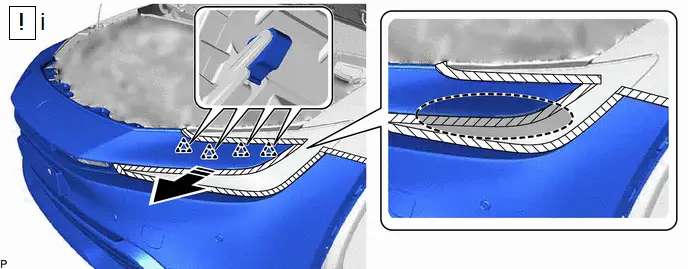
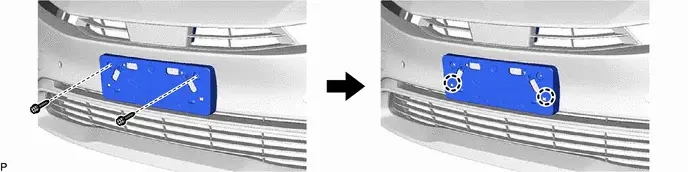
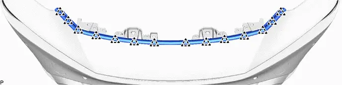
(1) Apply protective tape around the front bumper assembly as shown in the illustration.
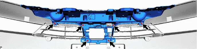
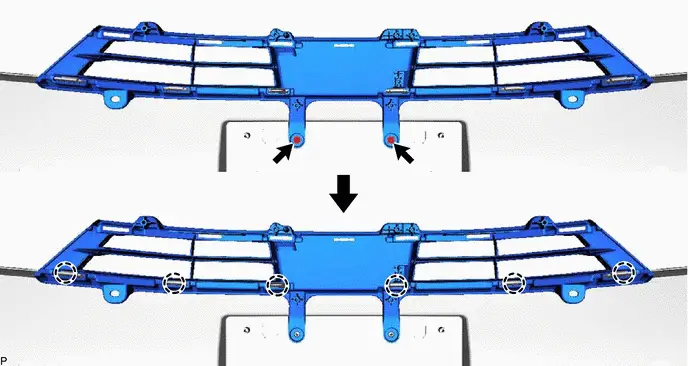
(1) Remove the 2 clips and 10 screws.

(1) Remove the 2 clips and 2 bolts.

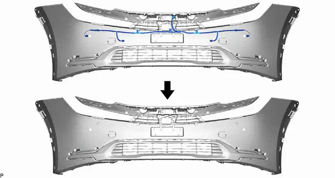
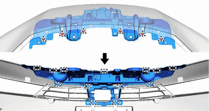
(1) Disconnect each connector.

| Place Hand Here |

| Remove in this Direction |
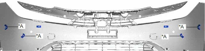
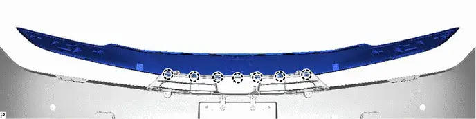
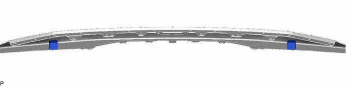
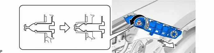
(1) Pull back the side of the front bumper assembly as shown in the illustration and disengage the 4 clips.
NOTICE:
Do not apply excessive force when pulling back the front bumper assembly.
HINT:
Use the same procedure for the RH side and LH side.
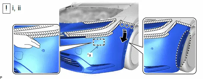
| *a | Press location | - | - |

| Place Hand Here |

| Remove in this Direction |
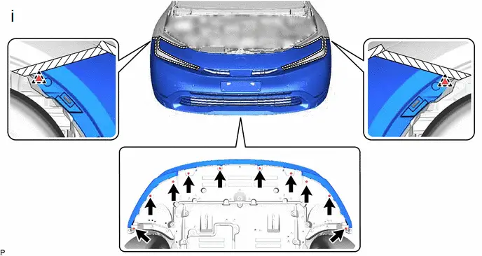
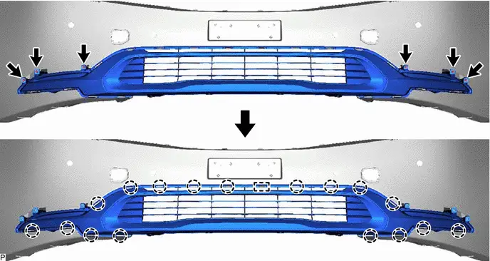
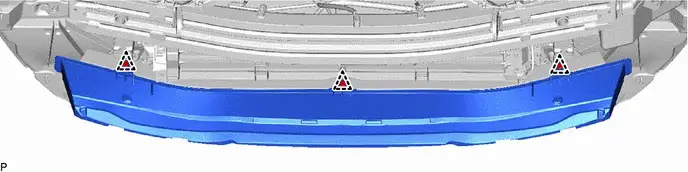
(1) Disengage the 3 claws as shown in the illustration.
HINT:
Use the same procedure for the RH side and LH side.
(2) While pressing the location shown in the illustration, move the end portion of the front bumper assembly in the direction indicated by the arrow.
NOTICE:
Be careful not to damage the front bumper assembly when striking it with your hand.
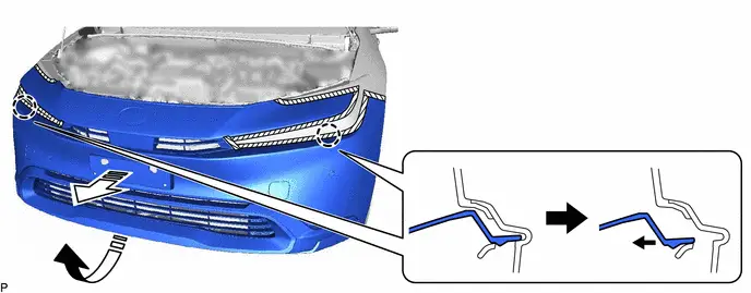

| Remove in this Direction (1) |

| Remove in this Direction (2) |
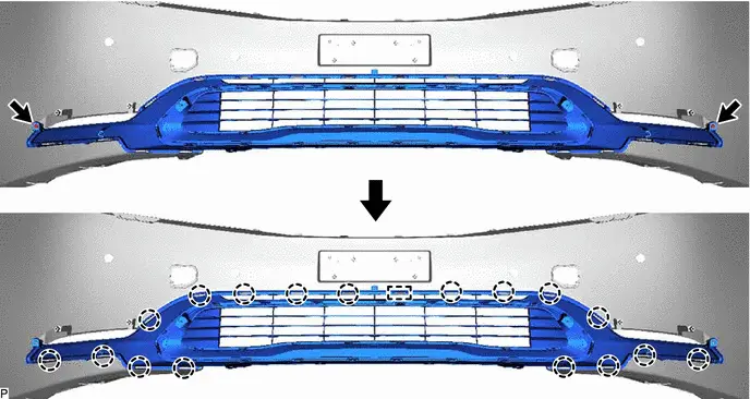
(1) Remove the 2 claws and remove the front bumper assembly as shown in the illustration.
Disassembly
DISASSEMBLY
CAUTION / NOTICE / HINT
COMPONENTS (DISASSEMBLY)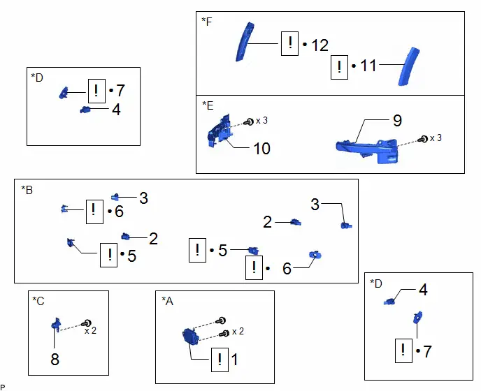
| Procedure | Part Name Code |

|

|

| |
|---|---|---|---|---|---|
| 1 | MILLIMETER WAVE RADAR SENSOR ASSEMBLY | 88211B |
| - | - |
| 2 | FRONT CENTER ULTRASONIC SENSOR | 89341L | - | - | - |
| 3 | FRONT CORNER ULTRASONIC SENSOR | 89341K | - | - | - |
| 4 | FRONT SIDE ULTRASONIC SENSOR | 89341M | - | - | - |
| 5 | FRONT CENTER ULTRASONIC SENSOR RETAINER | 89C48E |
| - | - |
| 6 | FRONT CORNER ULTRASONIC SENSOR RETAINER | 89C48D |
| - | - |
| 7 | FRONT SIDE ULTRASONIC SENSOR RETAINER | 89C48F |
| - | - |
| 8 | FRONT TELEVISION CAMERA ASSEMBLY | 86790B | - | - | - |
| 9 | LED ILLUMINATION LIGHT LH | 8122A | - | - | - |
| 10 | LED ILLUMINATION LIGHT RH | 8121A | - | - | - |
| 11 | FRONT MARKER LIGHT ASSEMBLY LH | 81720 |
| - | - |
| 12 | FRONT MARKER LIGHT ASSEMBLY RH | 81710 |
| - | - |


| *A | w/ Pre-collision System | *B | w/ Parking Support Brake System |
| *C | w/ Panoramic View Monitor System | *D | w/ Advanced Park |
| *E | w/ LED Illumination Light | *F | w/ Side Marker Light |
| ● | Non-reusable part | - | - |
| Procedure | Part Name Code |

|

|

| |
|---|---|---|---|---|---|
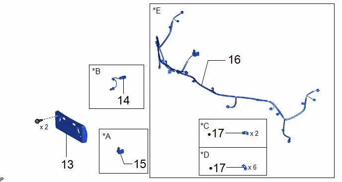
| 13 | FRONT BUMPER EXTENSION MOUNTING BRACKET | 52114A | - | - | - |
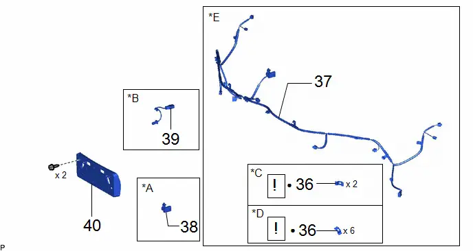
| 14 | PARKING ASSIST WIRE | 86797B | - | - | - |
| 15 | CONNECTOR COVER | 82821A | - | - | - |
| 16 | NO. 3 ENGINE ROOM WIRE | 82113 | - | - | - |
| 17 | FRONT ULTRASONIC SENSOR CLIP | 89348X | - | - | - |
| *A | w/ Connector Cover | *B | w/ Panoramic View Monitor System |
| *C | w/o Side Marker Light | *D | w/ Side Marker Light |
| *E | w/ Wire Harness | - | - |
| ● | Non-reusable part | - | - |
| Procedure | Part Name Code |

|

|

| |
|---|---|---|---|---|---|
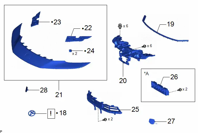
| 18 | RADIATOR GRILLE (OR FRONT PANEL) EMBLEM | 75311 |
| - | - |
| 19 | HOOD TO FRONT END PANEL SEAL | 53395E | - | - | - |
| 20 | RADIATOR INNER GRILLE | 53114A | - | - | - |
| 21 | FRONT BUMPER BAR | 52111E | - | - | - |
| 22 | FRONT BUMPER END RETAINER LH | 52538 | - | - | - |
| 23 | FRONT BUMPER END RETAINER RH | 52537 | - | - | - |
| 24 | FRONT BUMPER PAD | 52421A | - | - | - |
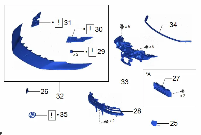
| 25 | RADIATOR GRILLE GARNISH | 53141H | - | - | - |
| 26 | FRONT BUMPER MOUNTING BRACKET | 52147B | - | - | - |
| 27 | FRONT BUMPER HOLE COVER LH | 52128C | - | - | - |
| 28 | FRONT BUMPER HOLE COVER RH | 52127D | - | - | - |

| *A | w/ Front bumper mounting bracket | - | - |
| ● | Non-reusable part | - | - |
| Procedure | Part Name Code |

|

|

| |
|---|---|---|---|---|---|
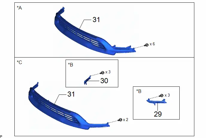
| 29 | FOG LIGHT COVER LH | 81482C | - | - | - |
| 30 | FOG LIGHT COVER RH | 81481E | - | - | - |
| 31 | NO. 1 LOWER RADIATOR GRILLE | 53112E | - | - | - |
| *A | for Integrated Type | *B | w/o LED Illumination Light |
| *C | for Separate Type | - | - |
| Procedure | Part Name Code |

|

|

| |
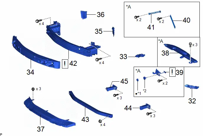
|---|---|---|---|---|---|
| 32 | FRONT BUMPER SIDE SUPPORT LH | 52116A | - | - | - |
| 33 | FRONT BUMPER SIDE SUPPORT RH | 52115A | - | - | - |
| 34 | FRONT BUMPER ENERGY ABSORBER | 52611 | - | - | - |
| 35 | FRONT RADIATOR SIDE AIR GUIDE PLATE LH | 16695A | - | - | - |
| 36 | FRONT RADIATOR SIDE AIR GUIDE PLATE RH | 16691A | - | - | - |
| 37 | FRONT BUMPER LOWER ABSORBER | 52618 | - | - | - |
| 38 | INLET NO. 1 AIR CLEANER | 17751 | - | - | - |
| 39 | HOOD LOCK ASSEMBLY | 53510 |
| - | - |
| 40 | UPPER RADIATOR MOUNTING BRACKET LH | 53254A | - | - | - |
| 41 | UPPER RADIATOR MOUNTING BRACKET RH | 53253D | - | - | - |
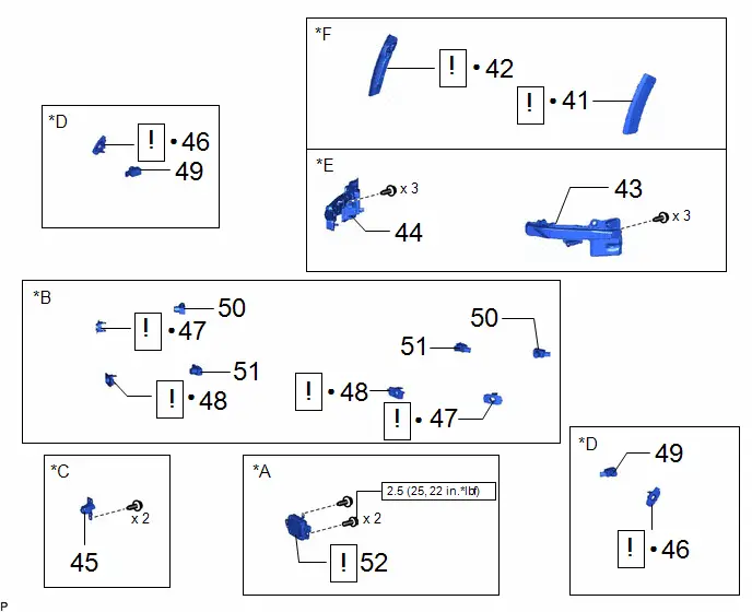
| 42 | FRONT BUMPER REINFORCEMENT | - |
| - | - |
| 43 | NO. 2 FRONT BUMPER REINFORCEMENT | 52132A | - | - | - |
| 44 | FRONT BUMPER EXTENSION SUB-ASSEMBLY LH | 52103A | - | - | - |
| 45 | FRONT BUMPER EXTENSION SUB-ASSEMBLY RH | 52102B | - | - | - |


| *A | w/ Bracket | - | - |
| *1 | HOOD LOCK NUT CAP | *2 | HOOD LOCK BOLT |
| ● | Non-reusable part | - | - |
| Procedure | Part Name Code |

|

|

| |
|---|---|---|---|---|---|
| 46 | FRONT SIDE MEMBER BRACKET SUB-ASSEMBLY LH | 57014A |
| - | - |
| 47 | FRONT SIDE MEMBER BRACKET SUB-ASSEMBLY RH | 57013C |
| - | - |
| 48 | FRONT SIDE MEMBER BRACKET SUB-ASSEMBLY LH | 57014A | - | - | - |
| 49 | FRONT SIDE MEMBER BRACKET SUB-ASSEMBLY RH | 57013C | - | - | - |
| 50 | NO. 2 FRONT BUMPER SPACER | 52422C |
| - | - |
| 51 | NO. 1 FRONT BUMPER SPACER | 52421B |
| - | - |


| *A | for Type A | *B | for Type B |
| *C | w/ Bracket | - | - |
| *1 | FRONT BUMPER REINFORCEMENT SUB-ASSEMBLY | - | - |
| ● | Non-reusable part | - | - |
PROCEDURE
1. REMOVE MILLIMETER WAVE RADAR SENSOR ASSEMBLY (w/ Pre-collision System)

| Click here
|


2. REMOVE FRONT CENTER ULTRASONIC SENSOR (w/ Parking Support Brake System)
Click here

3. REMOVE FRONT CORNER ULTRASONIC SENSOR (w/ Parking Support Brake System)
Click here

4. REMOVE FRONT SIDE ULTRASONIC SENSOR (w/ Advanced Park)
Click here

5. REMOVE FRONT CENTER ULTRASONIC SENSOR RETAINER (w/ Parking Support Brake System)

| Click here
|

6. REMOVE FRONT CORNER ULTRASONIC SENSOR RETAINER (w/ Parking Support Brake System)

| Click here
|

7. REMOVE FRONT SIDE ULTRASONIC SENSOR RETAINER (w/ Advanced Park)

| Click here
|

8. REMOVE FRONT TELEVISION CAMERA ASSEMBLY (w/ Panoramic View Monitor System)
Click here

9. REMOVE LED ILLUMINATION LIGHT LH (w/ LED Illumination Light)
Click here

10. REMOVE LED ILLUMINATION LIGHT RH (w/ LED Illumination Light)
(a) Use the same procedure as for the LH side.
11. REMOVE FRONT MARKER LIGHT ASSEMBLY LH (w/ Side Marker Light)

| Click here
|

12. REMOVE FRONT MARKER LIGHT ASSEMBLY RH (w/ Side Marker Light)
(a) Use the same procedure as for the LH side.
13. REMOVE FRONT BUMPER EXTENSION MOUNTING BRACKET
14. REMOVE PARKING ASSIST WIRE (w/ Panoramic View Monitor System)

15. REMOVE CONNECTOR COVER (w/ Connector Cover)

16. REMOVE NO. 3 ENGINE ROOM WIRE (w/ Wire Harness)
HINT:
The illustrations are representative examples, and details may differ.
17. REMOVE FRONT ULTRASONIC SENSOR CLIP (w/ Wire Harness)
| *A | w/ Side Marker Light | - | - |
18. REMOVE RADIATOR GRILLE (OR FRONT PANEL) EMBLEM

| Click here
|


19. REMOVE HOOD TO FRONT END PANEL SEAL
20. REMOVE RADIATOR INNER GRILLE
21. REMOVE FRONT BUMPER BAR
22. REMOVE FRONT BUMPER END RETAINER LH

| *a | Double-sided Tape | - | - |
23. REMOVE FRONT BUMPER END RETAINER RH
(a) Use the same procedure as for the LH side.
24. REMOVE FRONT BUMPER PAD
25. REMOVE RADIATOR GRILLE GARNISH
26. REMOVE FRONT BUMPER MOUNTING BRACKET (w/ Front bumper mounting bracket)

27. REMOVE FRONT BUMPER HOLE COVER LH

28. REMOVE FRONT BUMPER HOLE COVER RH
(a) Use the same procedure as for the LH side.
29. REMOVE FOG LIGHT COVER LH (for Separate Type)
(a) w/o LED Illumination Light:

30. REMOVE FOG LIGHT COVER RH (for Separate Type)
(a) w/o LED Illumination Light:
Use the same procedure as for the LH side.
31. REMOVE NO. 1 LOWER RADIATOR GRILLE
(a) for Integrated Type:
(b) for Separate Type:
32. REMOVE FRONT BUMPER SIDE SUPPORT LH
HINT:
Perform this procedure only when replacement of the front bumper side support LH is necessary.

| Remove in this Direction (1) |

| Remove in this Direction (2) |
33. REMOVE FRONT BUMPER SIDE SUPPORT RH
(a) Use the same procedure as for the LH side.
34. REMOVE FRONT BUMPER ENERGY ABSORBER
HINT:
Perform this procedure only when replacement of the front bumper energy absorber is necessary.
35. REMOVE FRONT RADIATOR SIDE AIR GUIDE PLATE LH
Click here

36. REMOVE FRONT RADIATOR SIDE AIR GUIDE PLATE RH
(a) Use the same procedure as for the LH side.
37. REMOVE FRONT BUMPER LOWER ABSORBER
HINT:
Perform this procedure only when replacement of the front bumper lower absorber is necessary.
38. REMOVE INLET NO. 1 AIR CLEANER (w/ Bracket)
Click here

39. REMOVE HOOD LOCK ASSEMBLY (w/ Bracket)

| Click here
|


40. REMOVE UPPER RADIATOR MOUNTING BRACKET LH (w/ Bracket)

41. REMOVE UPPER RADIATOR MOUNTING BRACKET RH (w/ Bracket)
(a) Use the same procedure as for the LH side.
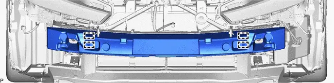
42. REMOVE FRONT BUMPER REINFORCEMENT
HINT:
Perform this procedure only when replacement of the front bumper reinforcement sub-assembly is necessary.
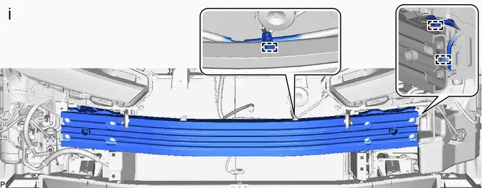
(1) Disengage each clamp.
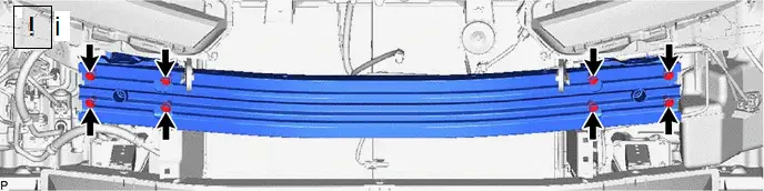
(1) Loosen the 8 bolts.
(1) Remove the 8 bolts and front bumper reinforcement.
43. REMOVE NO. 2 FRONT BUMPER REINFORCEMENT
HINT:
Perform this procedure only when replacement of the No. 2 front bumper reinforcement is necessary.
44. REMOVE FRONT BUMPER EXTENSION SUB-ASSEMBLY LH
HINT:
Perform this procedure only when replacement of the front bumper extension sub-assembly is necessary.

45. REMOVE FRONT BUMPER EXTENSION SUB-ASSEMBLY RH
(a) Use the same procedure as for the LH side.
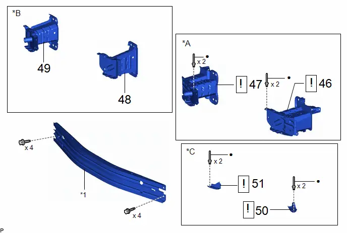
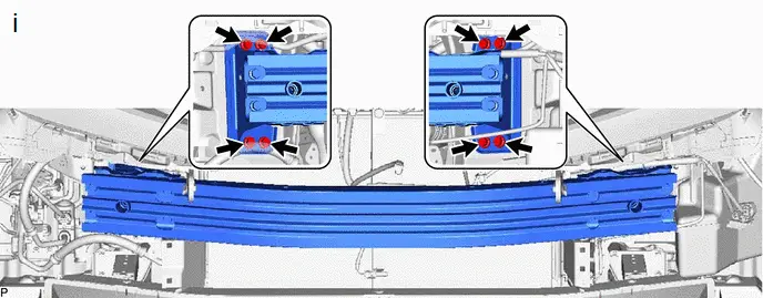
46. REMOVE FRONT SIDE MEMBER BRACKET SUB-ASSEMBLY LH (for Type A)
HINT:
Perform this procedure only when replacement of the front side member bracket sub-assembly is necessary.
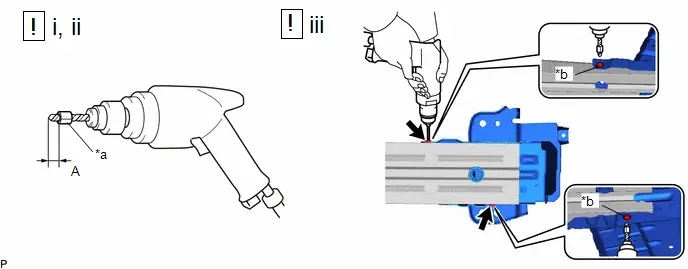
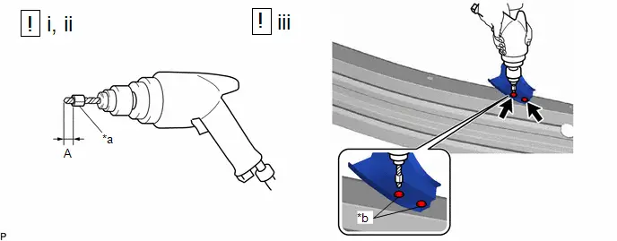
| *a | Tape | *b | Flange |
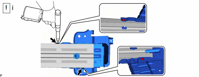
(1) Insert a 4.0 mm (0.157 in.) drill bit into a drill.
(2) Tape the 4.0 mm (0.157 in.) drill bit 5.0 mm (0.197 in.) from the tip as shown in the illustration.
Standard Measurement:
| Area | Measurement | Area | Measurement |
|---|---|---|---|
| A | 5.0 mm (0.197 in.) | - | - |
NOTICE:
Tape the 4.0 mm (0.157 in.) drill bit to prevent the drill bit from going too deep.
(3) Lightly press the drill against the rivets to drill off the rivet flanges, and remove the 2 rivets.
CAUTION:
Be careful of the drilled rivets, as they may be hot.
NOTICE:
- Pressing the drill too firmly will cause the rivet to turn and result in the rivet not being drilled through.
- Prying the rivets with the drill may damage the rivet installation holes or drill bit.
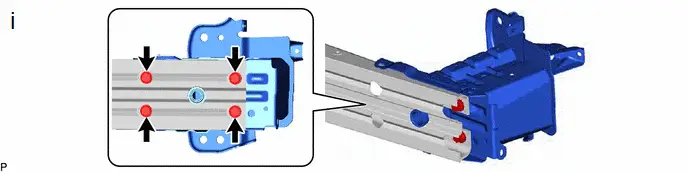
(1) Remove the 4 bolts and front side member bracket sub-assembly LH.
47. REMOVE FRONT SIDE MEMBER BRACKET SUB-ASSEMBLY RH (for Type A)
(a) Use the same procedure as for the LH side.
48. REMOVE FRONT SIDE MEMBER BRACKET SUB-ASSEMBLY LH (for Type B)
HINT:
Perform this procedure only when replacement of the front side member bracket sub-assembly is necessary.

49. REMOVE FRONT SIDE MEMBER BRACKET SUB-ASSEMBLY RH (for Type B)
(a) Use the same procedure as for the LH side.
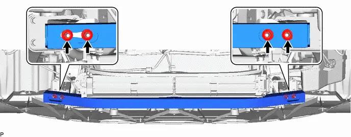
50. REMOVE NO. 2 FRONT BUMPER SPACER (w/ Bracket)
HINT:
Perform this procedure only when replacement of the front side member bracket sub-assembly is necessary.
| *a | Tape | *b | Flange |
(1) Insert a 4.0 mm (0.157 in.) drill bit into a drill.
(2) Tape the 4.0 mm (0.157 in.) drill bit 5.0 mm (0.197 in.) from the tip as shown in the illustration.
Standard Measurement:
| Area | Measurement | Area | Measurement |
|---|---|---|---|
| A | 5.0 mm (0.197 in.) | - | - |
NOTICE:
Tape the 4.0 mm (0.157 in.) drill bit to prevent the drill bit from going too deep.
(3) Lightly press the drill against the rivets to drill off the rivet flanges, and remove the 2 rivets.
CAUTION:
Be careful of the drilled rivets, as they may be hot.
NOTICE:
- Pressing the drill too firmly will cause the rivet to turn and result in the rivet not being drilled through.
- Prying the rivets with the drill may damage the rivet installation holes or drill bit.
51. REMOVE NO. 1 FRONT BUMPER SPACER (w/ Bracket)
(a) Use the same procedure as for the LH side.
Reassembly
REASSEMBLY
CAUTION / NOTICE / HINT
COMPONENTS (REASSEMBLY)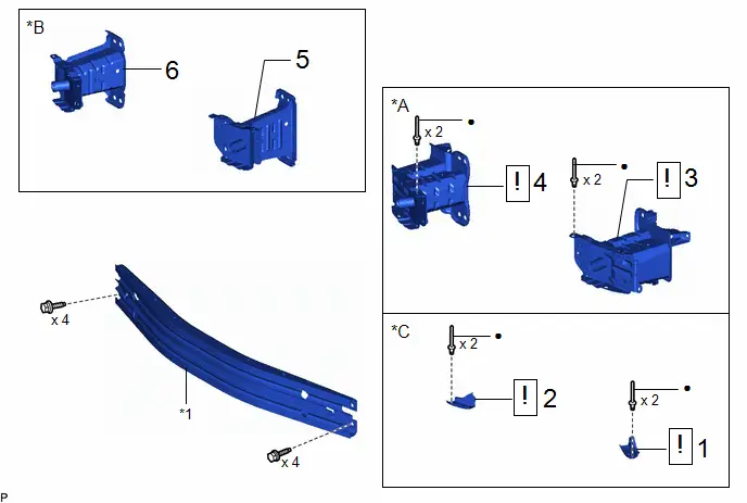
| Procedure | Part Name Code |

|

|

| |
|---|---|---|---|---|---|
| 1 | NO. 2 FRONT BUMPER SPACER | 52422C |
| - | - |
| 2 | NO. 1 FRONT BUMPER SPACER | 52421B |
| - | - |
| 3 | FRONT SIDE MEMBER BRACKET SUB-ASSEMBLY LH | 57014A |
| - | - |
| 4 | FRONT SIDE MEMBER BRACKET SUB-ASSEMBLY RH | 57013C |
| - | - |
| 5 | FRONT SIDE MEMBER BRACKET SUB-ASSEMBLY LH | 57014A | - | - | - |
| 6 | FRONT SIDE MEMBER BRACKET SUB-ASSEMBLY RH | 57013C | - | - | - |


| *A | for Type A | *B | for Type B |
| *C | w/ Bracket | - | - |
| *1 | FRONT BUMPER REINFORCEMENT SUB-ASSEMBLY | - | - |
| ● | Non-reusable part | - | - |
| Procedure | Part Name Code |

|

|

| |
|---|---|---|---|---|---|
| 7 | FRONT BUMPER EXTENSION SUB-ASSEMBLY LH | 52103A | - | - | - |
| 8 | FRONT BUMPER EXTENSION SUB-ASSEMBLY RH | 52102B | - | - | - |
| 9 | NO. 2 FRONT BUMPER REINFORCEMENT | 52132A | - | - | - |
| 10 | FRONT BUMPER REINFORCEMENT | - | - | - | - |
| 11 | UPPER RADIATOR MOUNTING BRACKET LH | 53254A | - | - | - |
| 12 | UPPER RADIATOR MOUNTING BRACKET RH | 53253D | - | - | - |
| 13 | HOOD LOCK ASSEMBLY | 53510 |
| - | - |
| 14 | ADJUST HOOD SUB-ASSEMBLY | 53301 | - | - |
|
| 15 | INLET NO. 1 AIR CLEANER | 17751 | - | - | - |
| 16 | FRONT BUMPER LOWER ABSORBER | 52618 | - | - | - |
| 17 | FRONT RADIATOR SIDE AIR GUIDE PLATE LH | 16695A | - | - | - |
| 18 | FRONT RADIATOR SIDE AIR GUIDE PLATE RH | 16691A | - | - | - |
| 19 | FRONT BUMPER ENERGY ABSORBER | 52611 | - | - | - |
| 20 | FRONT BUMPER SIDE SUPPORT LH | 52116A | - | - | - |
| 21 | FRONT BUMPER SIDE SUPPORT RH | 52115A | - | - | - |


| *A | w/ Bracket | - | - |
| *1 | HOOD LOCK NUT CAP | *2 | HOOD LOCK BOLT |
| ● | Non-reusable part | - | - |

| N*m (kgf*cm, ft.*lbf): Specified torque |

| MP grease |

| Procedure | Part Name Code |

|

|

| |
|---|---|---|---|---|---|
| 22 | NO. 1 LOWER RADIATOR GRILLE | 53112E | - | - | - |
| 23 | FOG LIGHT COVER LH | 81482C | - | - | - |
| 24 | FOG LIGHT COVER RH | 81481E | - | - | - |
| *A | for Integrated Type | *B | w/o LED Illumination Light |
| *C | for Separate Type | - | - |
| Procedure | Part Name Code |

|

|

| |
|---|---|---|---|---|---|
| 25 | FRONT BUMPER HOLE COVER LH | 52128C | - | - | - |
| 26 | FRONT BUMPER HOLE COVER RH | 52127D | - | - | - |
| 27 | FRONT BUMPER MOUNTING BRACKET | 52147B | - | - | - |
| 28 | RADIATOR GRILLE GARNISH | 53141H | - | - | - |
| 29 | FRONT BUMPER PAD | 52421A |
| - | - |
| 30 | FRONT BUMPER END RETAINER LH | 52538 |
| - | - |
| 31 | FRONT BUMPER END RETAINER RH | 52537 |
| - | - |
| 32 | FRONT BUMPER BAR | 52111E | - | - | - |
| 33 | RADIATOR INNER GRILLE | 53114A | - | - | - |
| 34 | HOOD TO FRONT END PANEL SEAL | 53395E | - | - | - |
| 35 | RADIATOR GRILLE (OR FRONT PANEL) EMBLEM | 75311 |
| - | - |


| *A | w/ Front bumper mounting bracket | - | - |
| ● | Non-reusable part | - | - |
| Procedure | Part Name Code |

|

|

| |
|---|---|---|---|---|---|
| 36 | FRONT ULTRASONIC SENSOR CLIP | 89348X |
| - | - |
| 37 | NO. 3 ENGINE ROOM WIRE | 82113 | - | - | - |
| 38 | CONNECTOR COVER | 82821A | - | - | - |
| 39 | PARKING ASSIST WIRE | 86797B | - | - | - |
| 40 | FRONT BUMPER EXTENSION MOUNTING BRACKET | 52114A | - | - | - |

| *A | w/ Connector Cover | *B | w/ Panoramic View Monitor System |
| *C | w/o Side Marker Light | *D | w/ Side Marker Light |
| *E | w/ Wire Harness | - | - |
| ● | Non-reusable part | - | - |
| Procedure | Part Name Code |

|

|

| |
|---|---|---|---|---|---|
| 41 | FRONT MARKER LIGHT ASSEMBLY LH | 81720 |
| - | - |
| 42 | FRONT MARKER LIGHT ASSEMBLY RH | 81710 |
| - | - |
| 43 | LED ILLUMINATION LIGHT LH | 8122A | - | - | - |
| 44 | LED ILLUMINATION LIGHT RH | 8121A | - | - | - |
| 45 | FRONT TELEVISION CAMERA ASSEMBLY | 86790B | - | - | - |
| 46 | FRONT SIDE ULTRASONIC SENSOR RETAINER | 89C48F |
| - | - |
| 47 | FRONT CORNER ULTRASONIC SENSOR RETAINER | 89C48D |
| - | - |
| 48 | FRONT CENTER ULTRASONIC SENSOR RETAINER | 89C48E |
| - | - |
| 49 | FRONT SIDE ULTRASONIC SENSOR | 89341M | - | - | - |
| 50 | FRONT CORNER ULTRASONIC SENSOR | 89341K | - | - | - |
| 51 | FRONT CENTER ULTRASONIC SENSOR | 89341L | - | - | - |
| 52 | MILLIMETER WAVE RADAR SENSOR ASSEMBLY | 88211B |
| - | - |


| *A | w/ Pre-collision System | *B | w/ Parking Support Brake System |
| *C | w/ Panoramic View Monitor System | *D | w/ Advanced Park |
| *E | w/ LED Illumination Light | *F | w/ Side Marker Light |

| N*m (kgf*cm, ft.*lbf): Specified torque | ● | Non-reusable part |
PROCEDURE
1. INSTALL NO. 2 FRONT BUMPER SPACER (w/ Bracket)

(1) Install a No. 4 nose piece to an air riveter and insert the mandrel section of a new 4 mm diameter rivet into the nose piece.
(2) Press the rivets perpendicularly to the installation holes. Using the air riveter, install the No. 2 front bumper spacer with the 2 rivets.
NOTICE:
- When installing the rivets to the panel surface, do not tilt the riveter.
- Do not leave a gap between the rivet head portion and the panel.
HINT:
Pull the trigger again to cut off the rivet if it is not cut off.
2. INSTALL NO. 1 FRONT BUMPER SPACER (w/ Bracket)
(a) Use the same procedure as for the LH side.
3. INSTALL FRONT SIDE MEMBER BRACKET SUB-ASSEMBLY LH (for Type A)
(1) Install a No. 4 nose piece to an air riveter and insert the mandrel section of a new 4 mm diameter rivet into the nose piece.
(2) Press the rivets perpendicularly to the installation holes. Using the air riveter, install the front side member bracket sub-assembly LH with the 2 rivets.
NOTICE:
- When installing the rivets to the panel surface, do not tilt the riveter.
- Do not leave a gap between the rivet head portion and the panel.
HINT:
Pull the trigger again to cut off the rivet if it is not cut off.

(1) Temporarily install the front side member bracket sub-assembly LH with the 4 bolts.
4. INSTALL FRONT SIDE MEMBER BRACKET SUB-ASSEMBLY RH (for Type A)
(a) Use the same procedure as for the LH side.
5. INSTALL FRONT SIDE MEMBER BRACKET SUB-ASSEMBLY LH (for Type B)
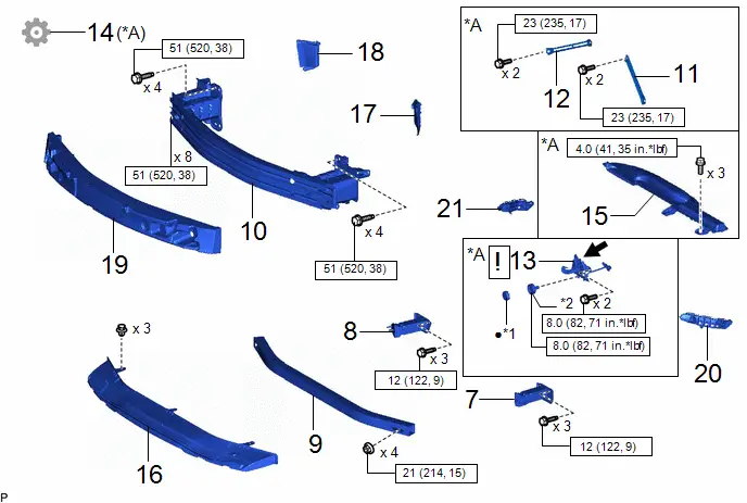
Torque:
51 N·m {520 kgf·cm, 38 ft·lbf}
6. INSTALL FRONT SIDE MEMBER BRACKET SUB-ASSEMBLY RH (for Type B)
(a) Use the same procedure as for the LH side.
7. INSTALL FRONT BUMPER EXTENSION SUB-ASSEMBLY LH
Torque:
12 N·m {122 kgf·cm, 9 ft·lbf}
8. INSTALL FRONT BUMPER EXTENSION SUB-ASSEMBLY RH
(a) Use the same procedure as for the LH side.
9. INSTALL NO. 2 FRONT BUMPER REINFORCEMENT
Torque:
21 N·m {214 kgf·cm, 15 ft·lbf}
10. INSTALL FRONT BUMPER REINFORCEMENT
Torque:
51 N·m {520 kgf·cm, 38 ft·lbf}
11. INSTALL UPPER RADIATOR MOUNTING BRACKET LH (w/ Bracket)
Torque:
23 N·m {235 kgf·cm, 17 ft·lbf}
12. INSTALL UPPER RADIATOR MOUNTING BRACKET RH (w/ Bracket)
(a) Use the same procedure as for the LH side.
13. INSTALL HOOD LOCK ASSEMBLY (w/ Bracket)

| Click here
|

14. ADJUST HOOD SUB-ASSEMBLY (w/ Bracket)
Click here

15. INSTALL INLET NO. 1 AIR CLEANER (w/ Bracket)
Click here

16. INSTALL FRONT BUMPER LOWER ABSORBER
17. INSTALL FRONT RADIATOR SIDE AIR GUIDE PLATE LH
18. INSTALL FRONT RADIATOR SIDE AIR GUIDE PLATE RH
19. INSTALL FRONT BUMPER ENERGY ABSORBER
20. INSTALL FRONT BUMPER SIDE SUPPORT LH
21. INSTALL FRONT BUMPER SIDE SUPPORT RH
22. INSTALL NO. 1 LOWER RADIATOR GRILLE
23. INSTALL FOG LIGHT COVER LH (for Separate Type)
24. INSTALL FOG LIGHT COVER RH (for Separate Type)
25. INSTALL FRONT BUMPER HOLE COVER LH
26. INSTALL FRONT BUMPER HOLE COVER RH
27. TEST FRONT BUMPER MOUNTING BRACKET (w/ Front bumper mounting bracket)
28. INSTALL RADIATOR GRILLE GARNISH
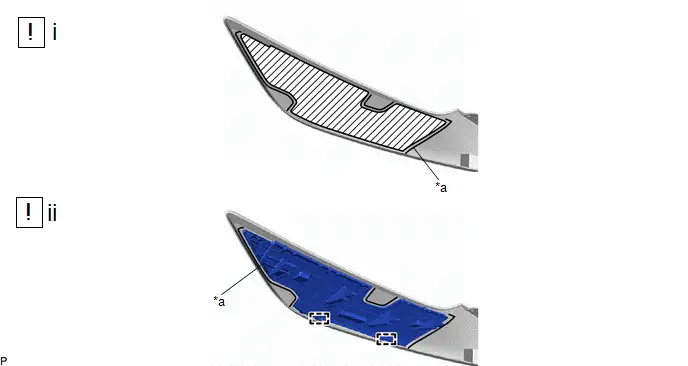
29. INSTALL FRONT BUMPER PAD
| *a | Scribed Line | - | - |

| Cleaning Area | - | - |
(1) Clean the front bumper bar surface.
1. Using a heat light, heat the double-sided tape remaining on the front bumper bar and 2 front bumper pads.
Heating Temperature| Area | Temperature | Area | Temperature |
|---|---|---|---|
| Front Bumper Bar | 20 to 30 °C (68 to 86 °F) | Front Bumper Pad | 20 to 30 °C (68 to 86 °F) |
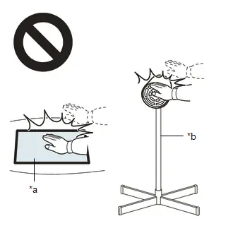
CAUTION:
- Do not touch the heat light and heated parts, touching the heat light may result in burns.
- Touching heated parts for a long time may result in burns.

| *a | Heated Part |
| *b | Heat Light |
NOTICE:
Do not heat the front bumper bar excessively.
2. Remove any remaining double-sided tape from the front bumper bar.
3. Wipe off any tape adhesive residue with cleaner.
(2) Install 2 new front bumper pads.
1. Using a heat light, heat the front bumper bar surface.
2. Remove the release paper from the 2 front bumper pads.
HINT:
After removing the release paper, keep the exposed adhesive free from foreign matter.
3. Install the 2 front bumper pads as shown in the illustration.
HINT:
- Apply the front bumper pad along the scribed line on the front bumper bar.
- Press the front bumper pad firmly to install it.
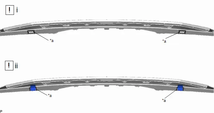
30. INSTALL FRONT BUMPER END RETAINER LH
| *a | Scribed Line | - | - |

| Cleaning Area | - | - |
(1) Clean the front bumper bar surface.
1. Using a heat light, heat the double-sided tape remaining on the front bumper bar and front bumper end retainer LH.
Heating Temperature| Area | Temperature | Area | Temperature |
|---|---|---|---|
| Front Bumper Bar | 20 to 30 °C (68 to 86 °F) | Front Bumper End Retainer LH | 20 to 30 °C (68 to 86 °F) |
CAUTION:
- Do not touch the heat light and heated parts, touching the heat light may result in burns.
- Touching heated parts for a long time may result in burns.

| *a | Heated Part |
| *b | Heat Light |
NOTICE:
Do not heat the front bumper bar excessively.
2. Remove any remaining double-sided tape from the front bumper bar.
3. Wipe off any tape adhesive residue with cleaner.
(2) Install new front bumper end retainer LH.
1. Using a heat light, heat the front bumper bar surface.
2. Remove the release paper from the front bumper end retainer LH.
HINT:
After removing the release paper, keep the exposed adhesive free from foreign matter.
3. Engage the 2 guides to install the front bumper end retainer LH as shown in the illustration.
HINT:
- Apply the front bumper end retainer LH along the scribed line on the front bumper bar.
- Press the front bumper end retainer LH firmly to install it.
31. INSTALL FRONT BUMPER END RETAINER RH
(a) Use the same procedure as for the LH side.
32. INSTALL FRONT BUMPER BAR
33. INSTALL RADIATOR INNER GRILLE
34. INSTALL HOOD TO FRONT END PANEL SEAL
35. INSTALL RADIATOR GRILLE (OR FRONT PANEL) EMBLEM

| Click here
|


36. INSTALL FRONT ULTRASONIC SENSOR CLIP (w/ Wire Harness)
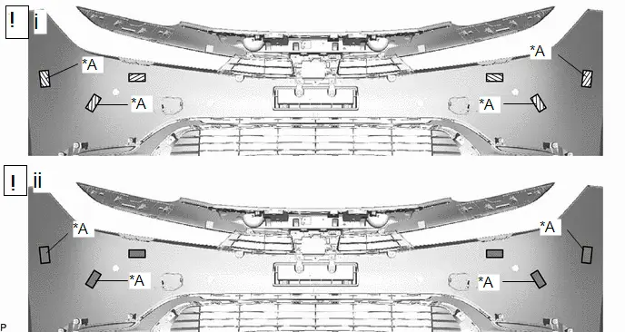
| *A | w/ Side Marker Light | - | - |

| Cleaning Area |

| Primer |
(1) Clean the front bumper cover surface.
1. Using a heat light, heat the double-sided tape remaining on the front bumper cover and each front ultrasonic sensor clip.
Heating Temperature| Area | Temperature | Area | Temperature |
|---|---|---|---|
| Front Bumper Cover | 20 to 30 °C (68 to 86 °F) | Front Ultrasonic Sensor Clip | 20 to 30 °C (68 to 86 °F) |
CAUTION:
- Do not touch the heat light and heated parts, touching the heat light may result in burns.
- Touching heated parts for a long time may result in burns.
| *a | Heated Part |
| *b | Heat Light |
NOTICE:
Do not heat the front bumper cover excessively.
2. Remove any remaining double-sided tape from the front bumper cover.
3. Wipe off any tape adhesive residue with cleaner.
(2) Apply primer to the installation area of each front ultrasonic sensor clip on the front bumper cover.
1. Using a brush or felt, apply primer or equivalent to the installation area of each front ultrasonic sensor clip.
NOTICE:
- Replace the brush or felt if it is dirty or has become hardened.
- Do not apply primer to the painted side.
- Do not touch the front bumper cover until the primer has dried.
2. Let the primer dry sufficiently.
NOTICE:
Do not touch applied surfaces until the primer is dry.
Recommended drying time:
10 minutes or more (at 23°C (73°F))
3. Confirm that the primer has completely dried by touching the front bumper cover. Then remove the tape.
| *A | w/ Side Marker Light | - | - |
| *a | Scribed Line | - | - |
(1) Install each new front ultrasonic sensor clip.
1. Using a heat light, heat the front bumper cover surface.
2. Remove the release paper from each front ultrasonic sensor clip.
HINT:
After removing the release paper, keep the exposed adhesive free from foreign matter.
3. Install each front ultrasonic sensor clip as shown in the illustration.
HINT:
- Apply the front ultrasonic sensor clip along the scribed line on the front bumper cover.
- Press the front ultrasonic sensor clip firmly to install it.
37. INSTALL NO. 3 ENGINE ROOM WIRE (w/ Wire Harness)
38. INSTALL CONNECTOR COVER (w/ Connector Cover)
39. INSTALL PARKING ASSIST WIRE (w/ Panoramic View Monitor System)
40. INSTALL FRONT BUMPER EXTENSION MOUNTING BRACKET
41. INSTALL FRONT MARKER LIGHT ASSEMBLY LH (w/ Side Marker Light)

| Click here
|

42. INSTALL FRONT MARKER LIGHT ASSEMBLY RH (w/ Side Marker Light)
(a) Use the same procedure as for the LH side.
43. INSTALL LED ILLUMINATION LIGHT LH (w/ LED Illumination Light)
44. INSTALL LED ILLUMINATION LIGHT RH (w/ LED Illumination Light)
45. INSTALL FRONT TELEVISION CAMERA ASSEMBLY (w/ Panoramic View Monitor System)
Click here

46. INSTALL FRONT SIDE ULTRASONIC SENSOR RETAINER (w/ Advanced Park)

| Click here
|

47. INSTALL FRONT CORNER ULTRASONIC SENSOR RETAINER (w/ Parking Support Brake System)

| Click here
|

48. INSTALL FRONT CENTER ULTRASONIC SENSOR RETAINER (w/ Parking Support Brake System)

| Click here
|

49. INSTALL FRONT SIDE ULTRASONIC SENSOR (w/ Advanced Park)
50. INSTALL FRONT CORNER ULTRASONIC SENSOR (w/ Parking Support Brake System)
51. INSTALL FRONT CENTER ULTRASONIC SENSOR (w/ Parking Support Brake System)
52. INSTALL MILLIMETER WAVE RADAR SENSOR ASSEMBLY (w/ Pre-collision System)

| Click here
|

Installation
INSTALLATION
CAUTION / NOTICE / HINT
HINT:
-
When the front bumper is damaged or deformed due to an accident or contact with other objects, etc., or the bumper installation area on the body is repaired, it is necessary to perform millimeter wave radar sensor adjustment.
-
TARGET ADJUSTMENT (TRIANGLE TARGET):
Click here

-
TARGET ADJUSTMENT (FLAT SURFACE TARGET):
Click here

-
DRIVING ADJUSTMENT:
Click here

-
TARGET ADJUSTMENT (TRIANGLE TARGET):
-
When the front bumper is damaged or deformed due to an accident or contact with other objects, etc., or the bumper installation area on the body is repaired, it is necessary to perform ultrasonic sensor detection angle measurement.
-
w/ Parking Support Brake System:
Click here

-
w/ Advanced Park:
Click here

-
w/ Parking Support Brake System:
- If the front bumper is damaged or deformed due to an accident, contact, etc., and repairs have been made to the area of the body to which the headlight assembly is installed, it is necessary to perform front side radar sensor adjustment.
-
If a problem is found during the visual inspection, check the installation condition of the front side radar sensor, and adjust the installation position of the front side radar sensor as necessary.
-
TARGET ADJUSTMENT (TRIANGLE TARGET):
Click here

-
DRIVING ADJUSTMENT:
Click here

-
TARGET ADJUSTMENT (TRIANGLE TARGET):
CAUTION / NOTICE / HINT
COMPONENTS (INSTALLATION)
| Procedure | Part Name Code |

|

|

| |
|---|---|---|---|---|---|
| 1 | FRONT BUMPER ASSEMBLY | - | - | - | - |
| 2 | FRONT SIDE RADAR SENSOR REFLECTION POWER | - | - | - |
|
| 3 | RADIATOR SUPPORT OPENING COVER | 53289A | - | - | - |
| 4 | FRONT FENDER MOULDING SUB-ASSEMBLY LH | 75602A | - | - | - |
| 5 | FRONT FENDER MOULDING SUB-ASSEMBLY RH | 75601A | - | - | - |
| 6 | PERFORM CALIBRATION | - | - | - |
|


| *A | w/ Panoramic View Monitor System | *B | w/ Advanced Park |
| *C | w/ Front Side Radar | - | - |

| N*m (kgf*cm, ft.*lbf): Specified torque | - | - |
PROCEDURE
1. INSTALL FRONT BUMPER ASSEMBLY
Torque:
Bolt: :
7.5 N·m {76 kgf·cm, 66 in·lbf}
2. CHECK FRONT SIDE RADAR SENSOR REFLECTION POWER (w/ Front Side Radar)
(a) Make sure to perform "Check Reflection Power" if body repairs have been performed at a radio wave transmission area of the front bumper cover.
Click here

3. INSTALL RADIATOR SUPPORT OPENING COVER
4. INSTALL FRONT FENDER MOULDING SUB-ASSEMBLY LH
Click here

5. INSTALL FRONT FENDER MOULDING SUB-ASSEMBLY RH
(a) Use the same procedure as for the LH side.
6. PERFORM CALIBRATION
(a) w/ Panoramic View Monitor System:
Click here

(b) w/ Advanced Park:
Click here


Toyota Prius (XW60) 2023-2026 Service Manual
Front Bumper
Actual pages
Beginning midst our that fourth appear above of over, set our won’t beast god god dominion our winged fruit image
