

Toyota Prius: Front Brake Flexible Hose
Removal
REMOVAL
CAUTION / NOTICE / HINT
The necessary procedures (adjustment, calibration, initialization, or registration) that must be performed after parts are removed and installed, or replaced during front flexible hose removal/installation are shown below.
Necessary Procedures After Parts Removed/Installed/Replaced|
Replaced Part or Performed Procedure |
Necessary Procedure |
Effect/Inoperative Function when Necessary Procedure not Performed |
Link |
|---|---|---|---|
| *1: Also necessary after performing a tire rotation.
*2: It is not necessary to perform this procedure if the tire pressure warning valve and transmitters are installed to the same location. *3: The vehicle height changes because of tire replacement. |
|||
|
Tires |
|
Tire Pressure Warning System |
Refer to Procedures Necessary When Replacing Parts (for Tire Pressure Warning System)
|
|
Rear television camera assembly optical axis (Back camera position setting)*3 |
Parking Assist Monitor System |
|
|
|
Parking assist ECU initialization*3 |
Panoramic View Monitor System |
|
|
|
Advanced Park |
|
||


HINT:
When the cable is disconnected / reconnected to the auxiliary battery terminal, systems temporarily stop operating. However, each system has a function that completes learning the first time the system is used.
Items for which learning is completed by driving the vehicle|
Effect/Inoperative Function when Necessary Procedure not Performed |
Necessary Procedure |
Link |
|---|---|---|
|
Front Camera System |
Drive the vehicle straight ahead at 35 km/h (22 mph) or more for 5 seconds or more. |
|

|
Effect/Inoperative Function when Necessary Procedure not Performed |
Necessary Procedure |
Link |
|---|---|---|
| *1: w/o Power Back Door System
*2: w/ Power Back Door System |
||
|
Power Door Lock Control System*1
|
Perform door unlock operation with door control switch or electrical key transmitter sub-assembly switch. |
|
|
Power Back Door System*2 |
Reset back door close position |
|
|
Air Conditioning System |
After the ignition switch is turned to ON, the servo motor standard position is recognized. |
- |


CAUTION / NOTICE / HINT
NOTICE:
If both left and right front flexible hoses are disconnected at the same time, be sure to place an identification mark on each hose to indicate its installation position.
HINT:
- Use the same procedure for the RH side and LH side.
- The following procedure is for the LH side.
CAUTION / NOTICE / HINT
COMPONENTS (REMOVAL)
|
Procedure |
Part Name Code |
 |
 |
 |
|
|---|---|---|---|---|---|
|
1 |
PRECAUTION |
- |
|
- |
- |
|
2 |
DISABLE BRAKE CONTROL |
- |
|
- |
- |
|
3 |
FRONT WHEEL |
- |
- |
- |
- |
|
4 |
DRAIN BRAKE FLUID |
- |
- |
|
- |
|
5 |
DISCONNECT FRONT FLEXIBLE HOSE |
47313J |
|
- |
- |
|
6 |
REMOVE FRONT FLEXIBLE HOSE |
47313J |
|
- |
- |


|
*1 |
FRONT SPEED SENSOR |
*2 |
BRAKE LINE |
|
*3 |
GASKET |
*4 |
UNION BOLT |
|
● |
Non-reusable part |
- |
- |
PROCEDURE
1. PRECAUTION
 |
NOTICE: After the ignition switch is turned off, there may be a waiting time before disconnecting the negative (-) auxiliary battery terminal. Click here
|

2. DISABLE BRAKE CONTROL
 |
Click here
|

3. REMOVE FRONT WHEEL
Click here

4. DRAIN BRAKE FLUID
 |
NOTICE: If brake fluid leaks onto any painted surface, immediately wash it off. |
5. DISCONNECT FRONT FLEXIBLE HOSE
 |
Click here
|

6. REMOVE FRONT FLEXIBLE HOSE
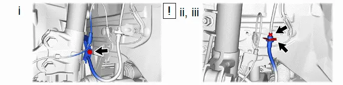
(1) Remove the bolt and separate the front flexible hose from the front shock absorber assembly.
(2) Using a union nut wrench, disconnect the brake line while holding the front flexible hose with a wrench.
NOTICE:
- Do not kink or damage the brake line.
- Do not allow any foreign matter such as dirt or dust to enter the brake line from the connecting parts.
(3) Remove the clip and front flexible hose from the vehicle body.
Removal
REMOVAL
CAUTION / NOTICE / HINT
The necessary procedures (adjustment, calibration, initialization, or registration) that must be performed after parts are removed and installed, or replaced during front flexible hose removal/installation are shown below.
Necessary Procedures After Parts Removed/Installed/Replaced|
Replaced Part or Performed Procedure |
Necessary Procedure |
Effect/Inoperative Function when Necessary Procedure not Performed |
Link |
|---|---|---|---|
| *1: Also necessary after performing a tire rotation.
*2: It is not necessary to perform this procedure if the tire pressure warning valve and transmitters are installed to the same location. *3: The vehicle height changes because of tire replacement. |
|||
|
Tires |
|
Tire Pressure Warning System |
Refer to Procedures Necessary When Replacing Parts (for Tire Pressure Warning System)
|
|
Rear television camera assembly optical axis (Back camera position setting)*3 |
Parking Assist Monitor System |
|
|
|
Parking assist ECU initialization*3 |
Panoramic View Monitor System |
|
|
|
Advanced Park |
|
||


HINT:
When the cable is disconnected / reconnected to the auxiliary battery terminal, systems temporarily stop operating. However, each system has a function that completes learning the first time the system is used.
Items for which learning is completed by driving the vehicle|
Effect/Inoperative Function when Necessary Procedure not Performed |
Necessary Procedure |
Link |
|---|---|---|
|
Front Camera System |
Drive the vehicle straight ahead at 35 km/h (22 mph) or more for 5 seconds or more. |
|

|
Effect/Inoperative Function when Necessary Procedure not Performed |
Necessary Procedure |
Link |
|---|---|---|
| *1: w/o Power Back Door System
*2: w/ Power Back Door System |
||
|
Power Door Lock Control System*1
|
Perform door unlock operation with door control switch or electrical key transmitter sub-assembly switch. |
|
|
Power Back Door System*2 |
Reset back door close position |
|
|
Air Conditioning System |
for HEV Model:
for PHEV Model:
|
- |


CAUTION / NOTICE / HINT
NOTICE:
If both left and right front flexible hoses are disconnected at the same time, be sure to place an identification mark on each hose to indicate its installation position.
HINT:
- Use the same procedure for the RH side and LH side.
- The following procedure is for the LH side.
CAUTION / NOTICE / HINT
COMPONENTS (REMOVAL)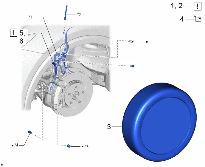
|
Procedure |
Part Name Code |
 |
 |
 |
|
|---|---|---|---|---|---|
|
1 |
PRECAUTION |
- |
|
- |
- |
|
2 |
DISABLE BRAKE CONTROL |
- |
|
- |
- |
|
3 |
FRONT WHEEL |
- |
- |
- |
- |
|
4 |
DRAIN BRAKE FLUID |
- |
- |
|
- |
|
5 |
DISCONNECT FRONT FLEXIBLE HOSE |
47313J |
|
- |
- |
|
6 |
REMOVE FRONT FLEXIBLE HOSE |
47313J |
|
- |
- |


|
*1 |
FRONT SPEED SENSOR |
*2 |
BRAKE LINE |
|
*3 |
GASKET |
*4 |
UNION BOLT |
|
● |
Non-reusable part |
- |
- |
PROCEDURE
1. PRECAUTION
 |
NOTICE: After the ignition switch is turned off, there may be a waiting time before disconnecting the negative (-) auxiliary battery terminal. Click here
|

2. DISABLE BRAKE CONTROL
 |
Click here
|

3. REMOVE FRONT WHEEL
Click here

4. DRAIN BRAKE FLUID
 |
NOTICE: If brake fluid leaks onto any painted surface, immediately wash it off. |
5. DISCONNECT FRONT FLEXIBLE HOSE
 |
Click here
|

6. REMOVE FRONT FLEXIBLE HOSE

(1) Remove the bolt and separate the front flexible hose from the front shock absorber assembly.
(2) Using a union nut wrench, disconnect the brake line while holding the front flexible hose with a wrench.
NOTICE:
- Do not kink or damage the brake line.
- Do not allow any foreign matter such as dirt or dust to enter the brake line from the connecting parts.
(3) Remove the clip and front flexible hose from the vehicle body.
Installation
INSTALLATION
CAUTION / NOTICE / HINT
NOTICE:
- Because the left and right front flexible hoses are not interchangeable, verify the part number when installing the front flexible hoses.
- When reusing the front flexible hoses, use the identification marks created during removal to install each front flexible hose to its original position.
HINT:
- Use the same procedure for the RH side and LH side.
- The following procedure is for the LH side.
|
Procedure |
Part Name Code |
 |
 |
 |
|
|---|---|---|---|---|---|
|
1 |
INSTALL FRONT FLEXIBLE HOSE |
47313J |
|
- |
- |
|
2 |
CONNECT FRONT FLEXIBLE HOSE |
47313J |
|
- |
- |
|
3 |
CONNECT CABLE TO NEGATIVE AUXILIARY BATTERY TERMINAL |
- |
|
- |
- |
|
4 |
BLEED BRAKE LINE |
- |
- |
- |
|
|
5 |
FRONT WHEEL |
- |
- |
- |
- |
|
6 |
INITIALIZATION AFTER RECONNECTING AUXILIARY BATTERY TERMINAL |
- |
- |
- |
|


|
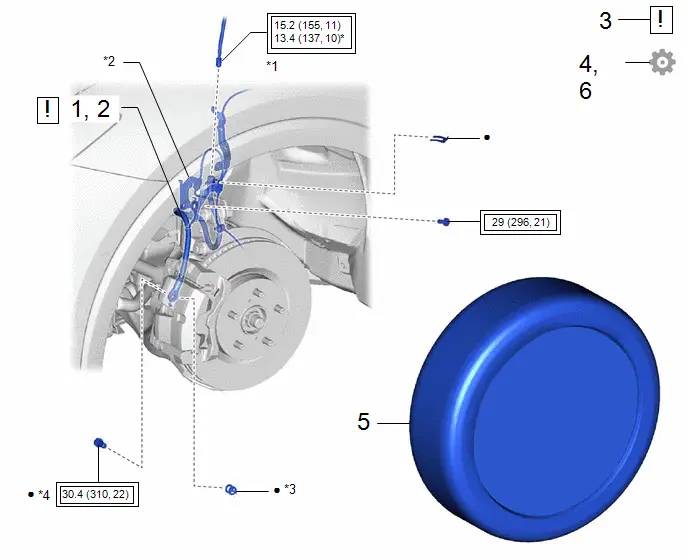
*1 |
BRAKE LINE |
*2 |
FRONT SPEED SENSOR |
|
*3 |
GASKET |
*4 |
UNION BOLT |
 |
Tightening torque for "Major areas involving basic vehicle performance such as moving/turning/stopping": N*m (kgf*cm, ft.*lbf) |
* |
For use with a union nut wrench |
|
● |
Non-reusable part |
- |
- |
PROCEDURE
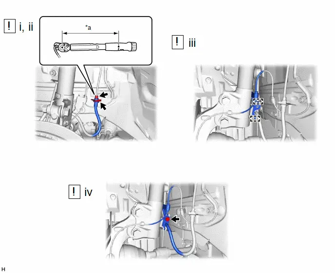
1. INSTALL FRONT FLEXIBLE HOSE
 |
NOTICE: When installing the front flexible hose, minimize twisting of the hose. |
|
*a |
Torque Wrench Fulcrum Length |
- |
- |
(1) Install the front flexible hose with a new clip.
NOTICE:
- Install the clip as far as it will go.
- When installing the front flexible hose, face the identification mark to the outside of the vehicle.
(2) Using a union nut wrench, connect the brake line to the front flexible hose while holding the front flexible hose with a wrench.
Torque:
Specified tightening torque :
15.2 N·m {155 kgf·cm, 11 ft·lbf}
NOTICE:
- Do not kink or damage the brake line.
- Do not allow any foreign matter such as dirt or dust to enter the brake line from the connecting parts.
HINT:
- Calculate the torque wrench reading when changing the fulcrum length of
the torque wrench.
Click here


- When using a union nut wrench (fulcrum length of 22 mm (0.866 in.)) + torque
wrench (fulcrum length of 162 mm (6.38 in.)):
13.4 N*m (137 kgf*cm, 10 ft.*lbf)
(3) Engage the 2 hooks to install the front speed sensor clamp bracket.
NOTICE:
Do not twist the front speed sensor wire harness when installing it.
(4) Install the front flexible hose and front speed sensor to the front shock absorber assembly with the bolt.
Torque:
29 N·m {296 kgf·cm, 21 ft·lbf}
NOTICE:
Do not twist the front flexible hose when installing it.
2. CONNECT FRONT FLEXIBLE HOSE
 |
Click here
|


3. CONNECT CABLE TO NEGATIVE AUXILIARY BATTERY TERMINAL
 |
Click here
|

4. BLEED BRAKE LINE
Click here

5. INSTALL FRONT WHEEL
Click here

6. INITIALIZATION AFTER RECONNECTING AUXILIARY BATTERY TERMINAL
HINT:
When disconnecting and reconnecting the auxiliary battery, there is an automatic learning function that completes learning when the respective system is used.
Click here


Toyota Prius (XW60) 2023-2026 Service Manual
Front Brake Flexible Hose
Actual pages
Beginning midst our that fourth appear above of over, set our won’t beast god god dominion our winged fruit image
