

Toyota Prius: Electric Parking Brake System
- Precaution
- Parts Location
- System Diagram
- How To Proceed With Troubleshooting
- Problem Symptoms Table
- Terminals Of Ecu
- Dtc Check / Clear
- Freeze Frame Data
- Inspection
- VEHICLE CONTROL HISTORY (RoB)
- Brake System Control Module "A" System Internal Failure (C059704,C059746,C13CF1C,C13D41C)
- Electric Parking Brake Switch Circuit Open (C060913)
- Electric Parking Brake Switch Signal Compare Failure (C060962)
- Left Electric Parking Brake Actuator Control Circuit Short to Ground (C060B11)
- Left Electric Parking Brake Actuator Control Circuit Short to Battery (C060B12)
- Left Electric Parking Brake Actuator Circuit Current Above Threshold (C060E19)
- Left Electric Parking Brake Actuator Signal Stuck In Range (C060E2A)
- Ignition Switch On/Start Position Circuit Short to Ground or Open (C102014)
- Electric Parking Brake Actuator Supply Voltage Circuit Voltage Below Threshold (C13B516)
- Electric Parking Brake Actuator (C13B800)
- Electric Parking Brake does not Operate
- Message Not Displayed on Multi-information Display When AUTO Function Set to ON/OFF
- Brake Warning Light (Yellow) Remains On
- Electric Parking Brake System AUTO Function Circuit
Precaution
PRECAUTION
PRECAUTION FOR DISCONNECTING CABLE FROM NEGATIVE AUXILIARY BATTERY TERMINAL
NOTICE:
-
After the ignition switch is turned off, there may be a waiting time before disconnecting the negative (-) auxiliary battery terminal.
Click here

HINT:
When disconnecting and reconnecting the auxiliary battery, there is an automatic learning function that completes learning when the respective system is used.
Click here


PRECAUTIONS FOR REMOVAL, INSTALLATION AND REPLACEMENT OF COMPONENTS
(a) After replacing certain components, it may be necessary to update the ECU security key.
Click here


(b) Perform "Calibration" after removal, installation or replacement of any of the following components:
Click here

- No. 1 skid control ECU (brake booster with master cylinder assembly)
- No. 2 skid control ECU (brake actuator assembly)
TROUBLESHOOTING PRECAUTIONS
(a) When inspecting the rear brakes, disconnect the connector or disconnect the cable from the negative (-) auxiliary battery terminal in order to shut off the supply of electrical power.
CAUTION:
- Do not perform the rear brake inspection while either the connector or the negative (-) auxiliary battery terminal are connected.
- The rear disc brake piston could operate, resulting in an accident such as hands being caught.
(b) When disconnecting a connector or removing a fuse or relay, make sure that the ignition switch has been off, the brake pedal has not been depressed, and the driver door has been closed for 4 minutes or more*.
- *: The electric parking brake may still operate up to 60 minutes depending on the state of the Toyota Prius vehicle after the ignition switch is turned off, so be sure to perform the work procedures with the vehicle on a level surface.
(c) When any parts have been removed or installed, check for DTCs after completion of installation to confirm that the system is operating correctly.
HINT:
After performing work procedures such as installation, if the parking brake indicator light (red) is blinking, the parking brake must be released.
HANDLING PRECAUTIONS
(a) When tilting the Toyota Prius vehicle to perform work after parking the vehicle on a level surface, the braking force may not be sufficient. Make sure to pull the electric parking brake switch (electric parking brake switch assembly) to the lock side 2 times (2 lock operations).
HINT:
- The electric parking brake system determines the amount of force used to operate the parking brake according to the tilt angle detected by the acceleration sensor (airbag ECU assembly).
- When the parking brake indicator is illuminated after the electric parking brake switch (electric parking brake switch assembly) has been pulled to the lock side, the maximum amount of braking force is applied if the electric parking brake switch (electric parking brake switch assembly) is pulled to the lock side one more time.
(b) The parking brake indicator light blinks when the ignition switch is turned to ON after replacing the No. 2 skid control ECU (brake actuator assembly). Operate the electric parking brake switch (electric parking brake switch assembly) to turn off the parking brake indicator light.
PRECAUTIONS FOR TOWING Toyota Prius VehicleS
(a) For towing precautions: Click here


PARKING BRAKE FORCED RELEASE METHOD
(a) For the parking brake forced release method: Click here

Parts Location
PARTS LOCATION
ILLUSTRATION
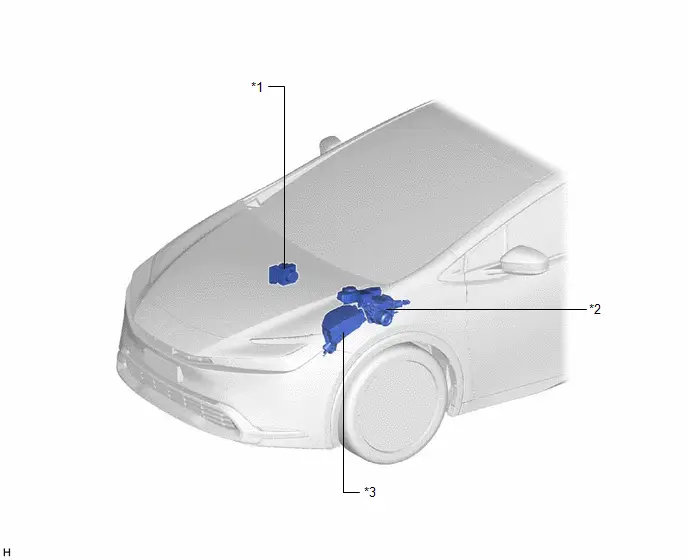
| *1 | BRAKE ACTUATOR ASSEMBLY - NO. 2 SKID CONTROL ECU | *2 | BRAKE BOOSTER WITH MASTER CYLINDER ASSEMBLY - NO. 1 SKID CONTROL ECU |
| *3 | NO. 1 ENGINE ROOM RELAY BLOCK AND NO. 1 JUNCTION BLOCK ASSEMBLY - ABS NO. 2 FUSE | - | - |
ILLUSTRATION
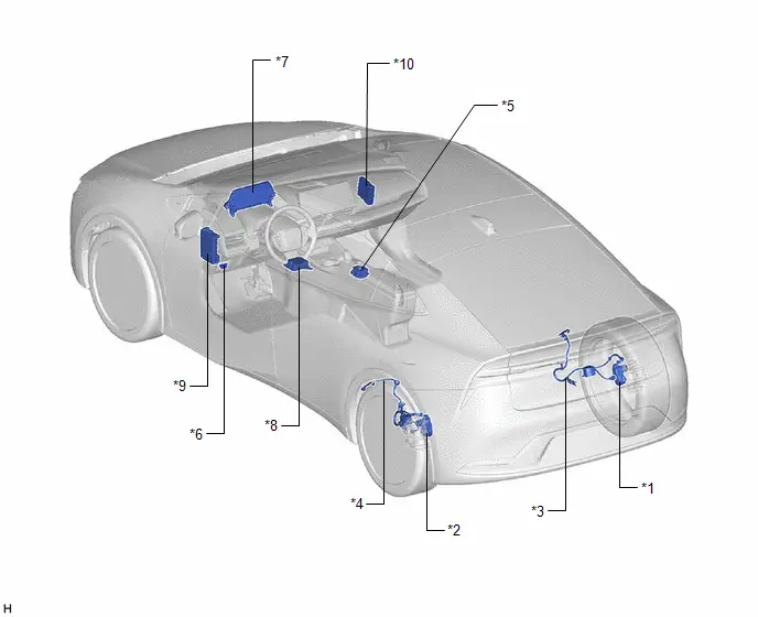
| *1 | PARKING BRAKE ACTUATOR ASSEMBLY RH | *2 | PARKING BRAKE ACTUATOR ASSEMBLY LH |
| *3 | NO. 1 PARKING BRAKE WIRE ASSEMBLY | *4 | NO. 2 PARKING BRAKE WIRE ASSEMBLY |
| *5 | ELECTRIC PARKING BRAKE SWITCH ASSEMBLY | *6 | DLC3 |
| *7 | COMBINATION METER ASSEMBLY | *8 | AIRBAG ECU ASSEMBLY - ACCELERATION SENSOR |
| *9 | POWER DISTRIBUTION BOX ASSEMBLY - ECU-IGR NO. 2 FUSE | *10 | HYBRID Toyota Prius Vehicle CONTROL ECU |
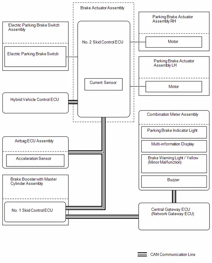
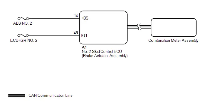
System Diagram
SYSTEM DIAGRAM
How To Proceed With Troubleshooting
CAUTION / NOTICE / HINT
HINT:
*: Use the GTS.
PROCEDURE
| 1. | VEHICLE BROUGHT TO WORKSHOP |
|

| 2. | CUSTOMER PROBLEM ANALYSIS |
(a) Interview the customer and confirm the problem.
Click here

|

| 3. | INSPECT AUXILIARY BATTERY VOLTAGE |
(a) Measure the auxiliary battery voltage with the ignition switch off.
Standard Voltage:
11 to 14 V (Ignition switch off)
- If the voltage is below 11 V, replace or recharge the auxiliary battery before proceeding to the next step.
|

| 4. | CHECK DTC AND FREEZE FRAME DATA* |
(a) Check and record DTCs and freeze frame data.
Chassis > Brake/EPB > Trouble Codes(b) Clear the DTCs and freeze frame data.
Chassis > Brake/EPB > Clear DTCs(c) Recheck for DTCs.
(1) Reconfirm the DTCs based on the recorded DTCs and freeze frame data.
Chassis > Brake/EPB > Trouble Codes(2) Try to reproduce the problem symptoms based on the recorded DTCs and freeze frame data, and then check if the DTCs are output again.
| Result | Proceed to |
|---|---|
| DTCs are not output (Problem symptom occurs.) | A |
| DTCs are output | B |
| DTCs are not output (Problem symptom does not occur.) | C |
HINT:
- Refer to Diagnostic Trouble Code Chart if any DTCs are output.
- When DTCs indicating a CAN communication system malfunction are output, first troubleshoot and repair the CAN communication system.
| B |

| GO TO DIAGNOSTIC TROUBLE CODE CHART |
| C |

| USE SIMULATION METHOD TO CHECK |
|

| 5. | PROBLEM SYMPTOMS TABLE |
(a) Proceed to Problem Symptoms Table.
Click here

| Result | Proceed to |
|---|---|
| Fault is not listed in Problem Symptoms Table | A |
| Fault is listed in Problem Symptoms Table | B |
| B |

| GO TO STEP 7 |
|

| 6. | OVERALL ANALYSIS AND TROUBLESHOOTING* |
(a) Refer to Terminals of ECU.
Click here

(b) Refer to Data List / Active Test.
Click here

|

| 7. | REPAIR OR REPLACE |
|

| 8. | CONFIRMATION TEST |
| NEXT |

| END |
Problem Symptoms Table
PROBLEM SYMPTOMS TABLE
HINT:
- Use the table below to help determine the cause of problem symptoms. If multiple suspected areas are listed, the potential causes of the symptoms are listed in order of probability in the "Suspected Area" column of the table. Check each symptom by checking the suspected areas in the order they are listed. Replace parts as necessary.
- Inspect the fuses and relays related to this system before inspecting the suspected areas below.
| Symptom | Suspected Area | Link |
|---|---|---|
| Electric parking brake does not operate | Proceed to "Electric Parking Brake does not Operate" |
|
| Parking brake indicator light does not illuminate or turn off when parking brake is manually engaged and disengaged | Proceed to "Electric Parking Brake does not Operate" |
|
| Electric parking brake AUTO function (shift-linked function) does not operate (shift-linked parking brake does not lock or release) | Proceed to "Electric Parking Brake AUTO Function Circuit" |
|
| Message not displayed on multi-information display when AUTO function set to ON/OFF | Proceed to "Message Not Displayed on Multi-information Display When AUTO Function Set to ON/OFF" |
|
| Brake system warning light (Yellow indicator) remains on | Proceed to "Brake Warning Light (Yellow) Remains On" |
|


Terminals Of Ecu
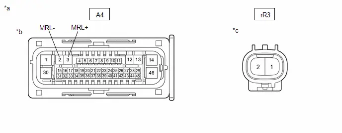
TERMINALS OF ECU
CHECK NO. 2 SKID CONTROL ECU (BRAKE ACTUATOR ASSEMBLY)
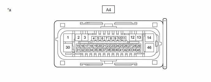
| *a | Front view of wire harness connector (to No. 2 Skid Control ECU (brake actuator assembly)) | - | - |
(a) Disconnect the A4 No. 2 skid control ECU (brake actuator assembly) connectors.
(b) Measure the voltage and resistance according to the value (s) in the table below.
| Terminal No. (Symbol) | Terminal Description | Condition | Specified Condition |
|---|---|---|---|
| A4-14 ( BS) - Body ground | Parking brake motor (parking brake actuator assembly) power supply | Always | 11 to 14 V |
| A4-45 (IG1) - Body ground | IG power supply | Ignition switch ON | 11 to 14 V |
| A4-1 (GND1) - Body ground | Ground | Always | Below 1 Ω |
| A4-13 (MRR ) | Parking brake motor RH (parking brake actuator assembly RH) ( ) | - | - |
| A4-12 (MRR-) | Parking brake motor RH (parking brake actuator assembly RH) (-) | - | - |
| A4-3 (MRL ) | Parking brake motor LH (parking brake actuator assembly LH) ( ) | - | - |
| A4-2 (MRL-) | Parking brake motor LH (parking brake actuator assembly LH) (-) | - | - |
| A4-36 (SWI1) | Electric parking brake switch (electric parking brake switch assembly) | - | - |
| A4-31 (SWO1) | Electric parking brake switch (electric parking brake switch assembly) | - | - |
| A4-41 (SWI2) | Electric parking brake switch (electric parking brake switch assembly) | - | - |
| A4-39 (SWO2) | Electric parking brake switch (electric parking brake switch assembly) | - | - |
| A4-27 (CANH) | CAN communication line (H) | - | - |
| A4-43 (CANL) | CAN communication line (L) | - | - |
| A4-16 (CA2H) | CAN communication line 2 (H) | - | - |
| A4-17 (CA2L) | CAN communication line 2 (L) | - | - |
Dtc Check / Clear
DTC CHECK / CLEAR
CHECK DTC AND FREEZE FRAME DATA
(a) Turn the ignition switch off.
(b) Connect the GTS to the DLC3.
(c) Turn the ignition switch to ON.
(d) Turn the GTS on.
(e) Enter the following menus: Chassis / Brake/EPB / Trouble Codes.
Chassis > Brake/EPB > Trouble Codes(f) Check for DTCs.
Click here
![]()
NOTICE:
The electric parking brake system outputs DTCs for the following system. When DTCs other than those in Diagnostic Trouble Code Chart for the electric parking brake system are output, refer to Diagnostic Trouble Code Chart for the relevant system.
| System | Proceed to |
|---|---|
| Electronically Controlled Brake System |
|
(g) Check the freeze frame data.
(1) If DTCs are output, check the freeze frame data and read the Toyota Prius vehicle status when the DTC was stored.
HINT:
for Freeze Frame Data: Click here
![]()
(h) Clear the DTCs.
Chassis > Brake/EPB > Clear DTCsHINT:
When DTCs are cleared, the freeze frame data will also be cleared.
Freeze Frame Data
FREEZE FRAME DATA
FREEZE FRAME DATA
HINT:
- When a DTC is stored, the freeze frame data stores the current vehicle (sensor) state as.
- The freeze frame data cannot be cleared or updated until the recorded DTCs are cleared.
(a) Using the GTS, the state of the Toyota Prius vehicle (sensors) when the system is operating or when a DTC was stored can be checked.
Chassis > Brake/EPB| Tester Display | Measurement Item | Range | Normal Condition | Diagnostic Note |
|---|---|---|---|---|
| FR Wheel Speed | Front wheel speed sensor RH reading | Min.: 0.0 km/h (0.0 mph) Max.: 6553.5 km/h (4072 mph) | Toyota Prius Vehicle stopped: 0.0 km/h (0 mph) | When driving at constant speed: No large fluctuations |
| FL Wheel Speed | Front wheel speed sensor LH reading | Min.: 0.0 km/h (0.0 mph) Max.: 6553.5 km/h (4072 mph) | Toyota Prius Vehicle stopped: 0.0 km/h (0 mph) | When driving at constant speed: No large fluctuations |
| RR Wheel Speed | Rear wheel speed sensor RH reading | Min.: 0.0 km/h (0.0 mph) Max.: 6553.5 km/h (4072 mph) | Toyota Prius Vehicle stopped: 0.0 km/h (0 mph) | When driving at constant speed: No large fluctuations |
| RL Wheel Speed | Rear wheel speed sensor LH reading | Min.: 0.0 km/h (0.0 mph) Max.: 6553.5 km/h (4072 mph) | Toyota Prius Vehicle stopped: 0.0 km/h (0 mph) | When driving at constant speed: No large fluctuations |
| Forward and Rearward G | Forward and rearward G | Min.: -25.105 m/s2 Max.: 24.908 m/s2 | During deceleration: -25.105 to 0.000 m/s2 During acceleration: 0.000 to 24.908 m/s2 | During acceleration/deceleration: Changes in proportion with acceleration |
| Accelerator Opening Angle % | Percentage of accelerator pedal opening angle | Min.: 0.0% Max.: 127.5% | Accelerator pedal released: 0.0% | During accelerator pedal operation: Changes in proportion with the pedal movement |
| Power Train Driving force | Powertrain output torque | Min.: -327680 N Max.: 327670 N | - | - |
| Gear Position | Gear position information | fail / 1st / 2nd / 3rd / 4th / 5th / 6th / 7th / 8th / 9th / 10th / P/N / R | Actual gear position | - |
| Shift Lever Position | Shift lever position information | fail / 1st / 2nd / 3rd / 4th / 5th / 6th / B / D/M / N / P / R / No input | Actual shift lever position | - |
| Brake Hold Control Mode | Brake hold control mode | Out of control mode / Pressure hold mode / Pressure release mode / EPB lock mode | Out of control mode: Brake hold control system is off or brake hold control system is stand-by mode (brake hold standby indicator light is illuminated) Pressure hold mode: Brake hold control is operating (brake hold operated indicator light is illuminated) Pressure release mode: Brake hold control is released (brake hold operated indicator light not illuminated) EPB lock mode: Parking brake is engaged during brake hold control | HINT:
|
| Toyota Prius Vehicle Speed | Vehicle speed (estimated vehicle speed used for various controls) | Min.: 0.0 km/h (0 mph) Max.: 6553.5 km/h (4072 mph) | Vehicle stopped: 0.0 km/h (0 mph) | When driving at constant speed: No large fluctuations |
| Toyota Prius Vehicle Speed Grade | Vehicle acceleration/deceleration | Min.: -25.105 m/s2 Max.: 24.908 m/s2 | Vehicle stopped: 0.000 m/s2 During deceleration: -25.105 to 0.000 m/s2 During acceleration: 0.000 to 24.908 m/s2 | During driving: Changes in proportion with Toyota Prius vehicle acceleration/deceleration |
| Parking Brake SW | Parking brake status | OFF / ON | OFF: Parking brake released ON: Parking brake applied | - |
| Deceleration Open | Acceleration sensor open detection | Normal / Under intermittent | Normal: Momentary interruption not detected Under intermittent: Momentary interruption detected | - |
| A/C ECU Communication Open | Air conditioning amplifier assembly communication open detection | Normal / Under intermittent | Normal: Momentary interruption not detected Under intermittent: Momentary interruption detected | - |
| HV Communication Open | Hybrid Toyota Prius vehicle control ECU communication open detection | Normal / Under intermittent | Normal: Momentary interruption not detected Under intermittent: Momentary interruption detected | - |
| ECU B1 Voltage | No. 2 skid control ECU (brake actuator assembly) B1 voltage | Min.: 0.0 V Max.: 25.5 V | 11.0 to 14.0 V | - |
| RH Actuator Motor Input Voltage | Parking brake motor RH (parking brake actuator assembly RH) input voltage | Min.: 0.0 V Max.: 25.5 V | - | - |
| LH Actuator Motor Input Voltage | Parking brake motor LH (parking brake actuator assembly LH) input voltage | Min.: 0.0 V Max.: 25.5 V | - | - |
| RH Actuator Motor Terminal Voltage | Parking brake motor RH (parking brake actuator assembly RH) positive ( ) terminal side voltage | Min.: 0.0 V Max.: 25.5 V | - | - |
| LH Actuator Motor Terminal Voltage | Parking brake motor LH (parking brake actuator assembly LH) positive ( ) terminal side voltage | Min.: 0.0 V Max.: 25.5 V | - | - |
| RH Actuator Motor -Terminal Voltage | Parking brake motor RH (parking brake actuator assembly RH) negative (-) terminal side voltage | Min.: 0.0 V Max.: 25.5 V | - | - |
| LH Actuator Motor -Terminal Voltage | Parking brake motor LH (parking brake actuator assembly LH) negative (-) terminal side voltage | Min.: 0.0 V Max.: 25.5 V | - | - |
| EPB Switch | Electric parking brake switch (electric parking brake switch assembly) input | Neutral / Apply / Release / Unknown | Neutral: Lock switch and release switch are off Apply: Lock switch on Release: Release switch on | When not normal, electric parking brake switch (electric parking brake switch assembly) release side system may be malfunctioning HINT: EPB stands for electric parking brake. |
| RH Actuator Motor Actual Current | Parking brake motor RH (parking brake actuator assembly RH) current value | Min.: -5.0362 A Max.: 50.5004 A | - | - |
| LH Actuator Motor Actual Current | Parking brake motor LH (parking brake actuator assembly LH) current value | Min.: -5.0362 A Max.: 50.5004 A | - | - |
| RH Actuator Motor Adjustment Current | Parking brake motor RH (parking brake actuator assembly RH) current calibration value | Min.: -6.9693 A Max.: 6.9148 A | - | - |
| LH Actuator Motor Adjustment Current | Parking brake motor LH (parking brake actuator assembly LH) current calibration value | Min.: -6.9693 A Max.: 6.9148 A | - | - |
| RH Actuator Motor Current Differential | Differences in parking brake motor RH (parking brake actuator assembly RH) monitoring current | Min.: -1.008 A Max.: 0.945 A | - | - |
| LH Actuator Motor Current Differential | Differences in parking brake motor LH (parking brake actuator assembly LH) monitoring current | Min.: -1.008 A Max.: 0.945 A | - | - |
| Toyota Prius Vehicle Speed (Control Value) | Vehicle speed (control value) | Min.: 0.0 km/h (0 mph) Max.: 6553.5 km/h (4072 mph) | - | - |
| Counter of IG ON After EPB Control Cancel | Number of times the ignition switch was turned to ON after EPB control was canceled | Min.: 0 Times Max.: 255 Times | - | HINT: EPB stands for electric parking brake. |
| RH Actuator Status | Parking brake actuator assembly RH condition | Park Applied / Hold Applied / Released / Applying / Releasing / Completely Released / Unknown | - | - |
| LH Actuator Status | Parking brake actuator assembly LH condition | Park Applied / Hold Applied / Released / Applying / Releasing / Completely Released / Unknown | - | - |
| EPB Warning Light | Brake system warning light (yellow indicator) output signal | OFF / ON | OFF: Brake system warning light (yellow indicator) turns off ON: Brake system warning light (yellow indicator) illuminates | HINT: EPB stands for electric parking brake. |
| Auto Mode Request | Auto mode request status | Manual mode request / Auto mode request | - | - |
| Brake Hold Ready | Brake hold control permission status | Not in stand-by mode / Stand-by mode | Not in stand-by mode: Brake hold function not operating (brake hold standby indicator light not illuminated) Stand-by mode: Brake hold function stand-by state (brake hold standby indicator light illuminated) | - |
| EPB Lock Request | Lock demand status | Not requested / requested | - | HINT: EPB stands for electric parking brake. |
| Auto Mode | AUTO (shift-linked) mode permission status | OFF / ON | OFF: Manual mode ON: AUTO (shift-linked) mode | - |
| Dynamic PKB Mode | Dynamic parking brake operation status | OFF / ON | OFF: Dynamic parking brake is not operating ON: Dynamic parking brake is operating | - |
| RH Actuator Motor Relay1 | Parking brake motor relay 1 RH condition | OFF / ON | - | - |
| RH Actuator Motor Relay2 | Parking brake motor relay 2 RH condition | OFF / ON | - | - |
| RH Actuator Motor Relay3 | Parking brake motor relay 3 RH condition | OFF / ON | - | - |
| RH Actuator Motor Relay4 | Parking brake motor relay 4 RH condition | OFF / ON | - | - |
| LH Actuator Motor Relay1 | Parking brake motor relay 1 LH condition | OFF / ON | - | - |
| LH Actuator Motor Relay2 | Parking brake motor relay 2 LH condition | OFF / ON | - | - |
| LH Actuator Motor Relay3 | Parking brake motor relay 3 LH condition | OFF / ON | - | - |
| LH Actuator Motor Relay4 | Parking brake motor relay 4 LH condition | OFF / ON | - | - |
| FR Speed Signal Status | Front wheel RH speed signal status | Normal / Fixed | Normal: Wheel speed signal not stuck Fixed: Wheel speed signal stuck | - |
| FL Speed Signal Status | Front wheel LH speed signal status | Normal / Fixed | Normal: Wheel speed signal not stuck Fixed: Wheel speed signal stuck | - |
| RR Speed Signal Status | Rear wheel RH speed signal status | Normal / Fixed | Normal: Wheel speed signal not stuck Fixed: Wheel speed signal stuck | - |
| RL Speed Signal Status | Rear wheel LH speed signal status | Normal / Fixed | Normal: Wheel speed signal not stuck Fixed: Wheel speed signal stuck | - |
| RH Actuator Current Status | Parking brake actuator assembly RH monitoring current condition | Normal / Invalid | Normal | - |
| LH Actuator Current Status | Parking brake actuator assembly LH monitoring current condition | Normal / Invalid | Normal | - |
| Permission of Interlocking Shift | AUTO (shift-linked) mode permission status | Available / Not available | - | - |
| Permission of Interlocking Brake | Brake-linked permission status | Available / Not available | - | - |
| Permission of RH Interlocking PKB Lock | Parking brake actuator assembly RH parking brake lock control permission status | Available / Not available | - | - |
| Permission of RH Interlocking PKB Release | Parking brake actuator assembly RH parking brake release control permission status | Available / Not available | - | - |
| Permission of RH Interlocking Dynamic PKB | Parking brake actuator assembly RH dynamic parking control permission status | Available / Not available | - | - |
| Permission of RH Interlocking PKB Full Release | Parking brake actuator assembly RH parking brake full release permission status | Available / Not available | - | - |
| Permission of LH Interlocking PKB Lock | Parking brake actuator assembly LH parking brake lock control permission status | Available / Not available | - | - |
| Permission of LH Interlocking PKB Release | Parking brake actuator assembly LH parking brake release control permission status | Available / Not available | - | - |
| Permission of LH Interlocking Dynamic PKB | Parking brake actuator assembly LH dynamic parking control permission status | Available / Not available | - | - |
| Permission of LH Interlocking PKB Full Release | Parking brake actuator assembly LH parking brake full release permission status | Available / Not available | - | - |
| Fade Status | Fade status | OFF / ON | - | - |
| RH Actuator Motor Current High | Parking brake motor RH (parking brake actuator assembly RH) overcurrent status | OFF / ON | - | - |
| RH Actuator Motor Driver Operation Status | Parking brake motor RH (parking brake actuator assembly RH) driver status | OFF / ON | - | - |
| LH Actuator Motor Current High | Parking brake motor LH (parking brake actuator assembly LH) overcurrent status | OFF / ON | - | - |
| LH Actuator Motor Driver Operation Status | Parking brake motor LH (parking brake actuator assembly LH) driver status | OFF / ON | - | - |
| IGR Voltage | IG1 voltage value | Min.: 0.0 V Max.: 25.5 V | - | Changes in proportion to auxiliary battery voltage |
| BS Voltage | BS voltage value | Min.: 0.0 V Max.: 25.5 V | - | Changes in proportion to auxiliary battery voltage |
Inspection
INSPECTION
PROCEDURE
1. INSPECT PARKING BRAKE ACTUATOR ASSEMBLY
(a) Parking brake actuator assembly operation inspection
| (1) Apply voltage to the terminals of the parking brake actuator assembly and check that it operates as specified. OK:
If the result is not as specified, replace the parking brake actuator assembly. |
|
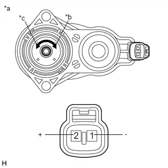
2. INSPECT ELECTRIC PARKING BRAKE SWITCH ASSEMBLY
(a) Check the resistance.
(1) Measure the resistance according to the value(s) in the table below.

| *a | Component without harness connected (Electric Parking Brake Switch Assembly) | - | - |
Standard Resistance:
 Click Location & Routing(K22) Click Connector(K22)
 | Tester Connection | Condition | Specified Condition | Result |
|---|---|---|---|
| K22-8 (SWI1) - K22-9 (SWO1) | OFF (Release) | 100 kΩ or higher | kΩ |
| K22-8 (SWI1) - K22-9 (SWO1) | ON (Lock) | 10 Ω or less | Ω |
| K22-8 (SWI1) - K22-9 (SWO1) | Switch not operated | 100 kΩ or higher | kΩ |
| K22-8 (SWI1) - K22-1 (SWI2) | OFF (Release) | 10 Ω or less | Ω |
| K22-8 (SWI1) - K22-1 (SWI2) | ON (Lock) | 10 Ω or less | Ω |
| K22-8 (SWI1) - K22-1 (SWI2) | Switch not operated | 100 kΩ or higher | kΩ |
| K22-8 (SWI1) - K22-2 (SWO2) | OFF (Release) | 10 Ω or less | Ω |
| K22-8 (SWI1) - K22-2 (SWO2) | ON (Lock) | 100 kΩ or higher | kΩ |
| K22-8 (SWI1) - K22-2 (SWO2) | Switch not operated | 10 Ω or less | Ω |
| K22-1 (SWI2) - K22-9 (SWO1) | OFF (Release) | 100 kΩ or higher | kΩ |
| K22-1 (SWI2) - K22-9 (SWO1) | ON (Lock) | 10 Ω or less | Ω |
| K22-1 (SWI2) - K22-9 (SWO1) | Switch not operated | 10 Ω or less | Ω |
| K22-1 (SWI2) - K22-2 (SWO2) | OFF (Release) | 10 Ω or less | Ω |
| K22-1 (SWI2) - K22-2 (SWO2) | ON (Lock) | 100 kΩ or higher | kΩ |
| K22-1 (SWI2) - K22-2 (SWO2) | Switch not operated | 100 kΩ or higher | kΩ |
If the result is not as specified, replace the electric parking brake switch assembly.
VEHICLE CONTROL HISTORY (RoB)
VEHICLE CONTROL HISTORY (RoB)
DESCRIPTION
- Vehicle Control History (RoB) is a function that captures and stores ECU data when triggered by specific vehicle behavior.
- If the customer states that the engine stalled or will not start, it may be possible to diagnose the cause of the malfunction by checking the Toyota Prius vehicle history information and Freeze Frame Data.
- The number of possible stored Freeze Frame Data sets, whether multi Freeze Frame Data is available, the number of freeze frame points, Freeze Frame Data items, the ECU internal range, etc., is different depending on the stored group.
-
The stored data items for Toyota Prius Vehicle Control History (RoB) Freeze Frame Data are different depending on the stored group. When the value of a data item does not change across all points, only the value of the detection point will be displayed. The contents of the Freeze Frame Data is almost the same as that of the Data List.
Click here

PRECAUTIONS
- As Toyota Prius Vehicle Control History (RoB) may be overwritten whenever the trigger conditions are met, make sure to save Vehicle Control History (RoB) before performing any inspections.
- As Vehicle Control History (RoB) may be stored when performing an Active Test, learning, etc., make sure to clear the Vehicle Control History (RoB) before returning the Toyota Prius vehicle to the customer.
CHECK VEHICLE CONTROL HISTORY (RoB) (ELECTRIC PARKING BRAKE SYSTEM)
HINT:
-
Vehicle Control History (RoB) of the electric parking brake system can be confirmed using the same menu for the electronically controlled brake system: Chassis / Brake/EPB / Utility / Toyota Prius Vehicle Control History (RoB)
Click here

Brake System Control Module "A" System Internal Failure (C059704,C059746,C13CF1C,C13D41C)
DESCRIPTION
The following DTCs are stored when a malfunction occurs in the No. 2 skid control ECU (brake actuator assembly).
| DTC No. | Detection Item | DTC Detection Condition | Trouble Area | Memory | DTC Output from | Priority | Note |
|---|---|---|---|---|---|---|---|
| C059704 | Brake System Control Module "A" System Internal Failure | No. 2 skid control ECU (brake actuator assembly) internal malfunction | No. 2 skid control ECU (brake actuator assembly) | DTC stored | Brake/EPB | A | An electric parking brake system malfunction is displayed on the multi-information display. |
| C059746 | Brake System Control Module "A" Calibration / Parameter Memory Failure | No. 2 skid control ECU (brake actuator assembly) internal malfunction | No. 2 skid control ECU (brake actuator assembly) | DTC stored | Brake/EPB | A | An electric parking brake system malfunction is displayed on the multi-information display. |
| C13CF1C | Left Electric Parking Brake Actuator Current Sensor Circuit Voltage Out of Range | No. 2 skid control ECU (brake actuator assembly) internal malfunction | No. 2 skid control ECU (brake actuator assembly) | DTC stored | Brake/EPB | A | An electric parking brake system malfunction is displayed on the multi-information display. |
| C13D41C | Right Electric Parking Brake Actuator Current Sensor Circuit Voltage Out of Range | No. 2 skid control ECU (brake actuator assembly) internal malfunction | No. 2 skid control ECU (brake actuator assembly) | DTC stored | Brake/EPB | A | An electric parking brake system malfunction is displayed on the multi-information display. |
PROCEDURE
| 1. | REPLACE NO. 2 SKID CONTROL ECU (BRAKE ACTUATOR ASSEMBLY) |
(a) Replace the No. 2 skid control ECU (brake actuator assembly).
HINT:
Click here


| NEXT |

| END |
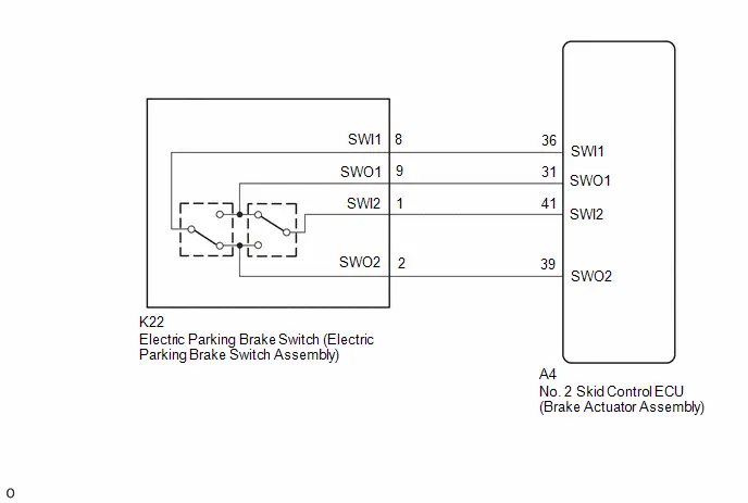
Electric Parking Brake Switch Circuit Open (C060913)
DESCRIPTION
When the electric parking brake switch is pulled, a lock request signal is sent from the No. 2 skid control ECU (brake actuator assembly) to the parking brake actuator assembly. When the electric parking brake switch is pushed, a release request signal is sent from the No. 2 skid control ECU (brake actuator assembly) to the parking brake actuator assembly.
| DTC No. | Detection Item | DTC Detection Condition | Trouble Area | Memory | DTC Output from | Priority | Note |
|---|---|---|---|---|---|---|---|
| C060913 | Electric Parking Brake Switch Circuit Open | Open detected in parking brake switch circuit for 1 second or more |
| DTC stored | Brake/EPB | B | An electric parking brake system malfunction is displayed on the multi-information display. |
WIRING DIAGRAM
CAUTION / NOTICE / HINT
NOTICE:
If the electric parking brake switch is held near the lock position but not fully in the lock position for 1 second or more, a DTC may be stored due to one of the two contacts being ON while the other is OFF. (This is not a system malfunction.)
PROCEDURE
| 1. | CHECK DTC |
(a) Check for DTCs.
Chassis > Brake/EPB > Trouble Codes| Result | Proceed to |
|---|---|
| Only C060913 is output | A |
| C060913 and C060962 are output | B |
| B |

| GO TO DTC C060962 |
|

| 2. | CHECK HARNESS AND CONNECTOR (NO. 2 SKID CONTROL ECU (BRAKE ACTUATOR ASSEMBLY) - ELECTRIC PARKING BRAKE SWITCH (ELECTRIC PARKING BRAKE SWITCH ASSEMBLY) |
Procedure1
(a) Make sure that there is no looseness at the locking part and the connecting part of the connectors.
OK:
The connector is securely connected.
Pre-procedure1
(b) Disconnect the K22 electric parking brake switch (electric parking brake switch assembly) connector.
(c) Disconnect the A4 No. 2 skid control ECU (brake actuator assembly) connector.
Procedure1
(d) Measure the resistance according to the value(s) in the table below.
Standard Resistance:
 Click Location & Routing(A4,K22) Click Connector(A4) Click Connector(K22)
 | Tester Connection | Condition | Specified Condition | Result |
|---|---|---|---|
| A4-36 (SWI1) - K22-8 (SWI1) | Always | Below 1 Ω | Ω |
| A4-31 (SWO1) - K22-9 (SWO1) | Always | Below 1 Ω | Ω |
| A4-41 (SWI2) - K22-1 (SWI2) | Always | Below 1 Ω | Ω |
| A4-39 (SWO2) - K22-2 (SWO2) | Always | Below 1 Ω | Ω |
| A4-36 (SWI1) or K22-8 (SWI1) - Body ground | Always | 10 kΩ or higher | kΩ |
| A4-31 (SWO1) or K22-9 (SWO1) - Body ground | Always | 10 kΩ or higher | kΩ |
| A4-41 (SWI2) or K22-1 (SWI2) - Body ground | Always | 10 kΩ or higher | kΩ |
| A4-39 (SWO2) or K22-2 (SWO2) - Body ground | Always | 10 kΩ or higher | kΩ |
Post-procedure1
(e) None
| OK |

| REPLACE NO. 2 SKID CONTROL ECU (BRAKE ACTUATOR ASSEMBLY)
|


| NG |

| REPAIR OR REPLACE HARNESS OR CONNECTOR |
Electric Parking Brake Switch Signal Compare Failure (C060962)
DESCRIPTION
Refer to DTC C060913.
Click here

| DTC No. | Detection Item | DTC Detection Condition | Trouble Area | Memory | DTC Output from | Priority | Note |
|---|---|---|---|---|---|---|---|
| C060962 | Electric Parking Brake Switch Signal Compare Failure |
|
| DTC stored | Brake/EPB | A | An electric parking brake system malfunction is displayed on the multi-information display. |
| Toyota Prius Vehicle Condition | |||||||
|---|---|---|---|---|---|---|---|
| Pattern 1 | Pattern 2 | Pattern 3 | Pattern 4 | Pattern 5 | Pattern 6 | ||
| Diagnosis Condition | Toyota Prius Vehicle is stopped | - | - | ○ | - | - | - |
| Toyota Prius Vehicle is being driven | - | - | - | ○ | - | - | |
| During initial check | - | - | - | - | ○ | - | |
| Parking brake switch is being operated | - | - | - | - | - | ○ | |
| Malfunction Status | Open detected in parking brake switch circuit | ○ | - | - | - | - | - |
| Short detected in parking brake switch circuit | - | ○ | - | - | - | - | |
| Stuck parking brake switch detected | - | - | ○ | ○ | ○ | ○ | |
| Detection Time | 1 second or more | 1 second or more | 30 seconds or more | 1 second or more | 1 second or more | - | |
| Number of Trips | 1 trip | 1 trip | 1 trip | 1 trip | 1 trip | 3 trip | |
HINT:
DTC will be output when conditions for either of the patterns in the table above are met.
WIRING DIAGRAM
Click here

CAUTION / NOTICE / HINT
NOTICE:
If the electric parking brake switch is held near the lock position but not fully in the lock position for 1 second or more, a DTC may be stored due to one of the two contacts being ON while the other is OFF. (This is not a system malfunction.)
PROCEDURE
| 1. | READ VALUE USING GTS (EPB SWITCH) |
Pre-procedure1
(a) Connect the GTS to the DLC3.
Pre-procedure2
(b) Turn the ignition switch to ON.
Pre-procedure3
(c) Enter the following menus: Chassis / Brake/EPB / Data List.
Chassis > Brake/EPB > Data List| Tester Display | Measurement Item | Range | Normal Condition | Diagnostic Note |
|---|---|---|---|---|
| EPB Switch | Electric parking brake switch (electric parking brake switch assembly) input | Neutral / Apply / Release / Unknown | Neutral: Lock switch and release switch are off Apply: Lock switch on Release: Release switch on | When not normal, electric parking brake switch (electric parking brake switch assembly) release side system may be malfunctioning HINT: EPB stands for electric parking brake. |
| Tester Display |
|---|
| EPB Switch |
Procedure1
(d) Operate the electric parking brake switch assembly and check that the value of "EPB Switch" in the Data List changes between Apply and Release in accordance with the operation of the switch.
OK:
The value of EPB Switch changes between Apply and Release in accordance with switch operation.
Post-procedure1
(e) None
| NG |

| GO TO STEP 4 |
|

| 2. | CLEAR DTC |
(a) Clear the DTCs.
Chassis > Brake/EPB > Clear DTCs
|

| 3. | CHECK DTC |
(a) Check for DTCs.
Chassis > Brake/EPB > Trouble Codes| Result | Proceed to |
|---|---|
| DTCs are output | A |
| DTCs are not output | B |
| A |

| REPLACE NO. 2 SKID CONTROL ECU (BRAKE ACTUATOR ASSEMBLY)
|


| B |

| USE SIMULATION METHOD TO CHECK |
| 4. | INSPECT ELECTRIC PARKING BRAKE SWITCH ASSEMBLY |
Click here

| NG |

| REPLACE ELECTRIC PARKING BRAKE SWITCH ASSEMBLY |
|

| 5. | CHECK HARNESS AND CONNECTOR (NO. 2 SKID CONTROL ECU (BRAKE ACTUATOR ASSEMBLY) - ELECTRIC PARKING BRAKE SWITCH (ELECTRIC PARKING BRAKE SWITCH ASSEMBLY) |
Pre-procedure1
(a) Disconnect the K22 electric parking brake switch (electric parking brake switch assembly) connector.
(b) Disconnect the A4 No. 2 skid control ECU (brake actuator assembly) connector.
Procedure1
(c) Measure the resistance according to the value(s) in the table below.
Standard Resistance:
 Click Location & Routing(A4,K22) Click Connector(A4) Click Connector(K22)
 | Tester Connection | Condition | Specified Condition | Result |
|---|---|---|---|
| A4-36 (SWI1) - K22-8 (SWI1) | Always | Below 1 Ω | Ω |
| A4-31 (SWO1) - K22-9 (SWO1) | Always | Below 1 Ω | Ω |
| A4-41 (SWI2) - K22-1 (SWI2) | Always | Below 1 Ω | Ω |
| A4-39 (SWO2) - K22-2 (SWO2) | Always | Below 1 Ω | Ω |
| A4-36 (SWI1) or K22-8 (SWI1) - Body ground | Always | 10 kΩ or higher | kΩ |
| A4-31 (SWO1) or K22-9 (SWO1) - Body ground | Always | 10 kΩ or higher | kΩ |
| A4-41 (SWI2) or K22-1 (SWI2) - Body ground | Always | 10 kΩ or higher | kΩ |
| A4-39 (SWO2) or K22-2 (SWO2) - Body ground | Always | 10 kΩ or higher | kΩ |
Post-procedure1
(d) None
| NG |

| REPAIR OR REPLACE HARNESS OR CONNECTOR |
|

| 6. | CLEAR DTC |
Pre-procedure1
(a) None
Procedure1
(b) Clear the DTCs.
Chassis > Brake/EPB > Clear DTCsPost-procedure1
(c) Turn the ignition switch off.
|

| 7. | CHECK DTC |
(a) Check for DTCs.
Chassis > Brake/EPB > Trouble Codes| Result | Proceed to |
|---|---|
| DTCs are output | A |
| DTCs are not output | B |
| A |

| REPLACE NO. 2 SKID CONTROL ECU (BRAKE ACTUATOR ASSEMBLY)
|


| B |

| USE SIMULATION METHOD TO CHECK |
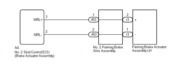
Left Electric Parking Brake Actuator Control Circuit Short to Ground (C060B11)
DESCRIPTION
| DTC No. | Detection Item | DTC Detection Condition | Trouble Area | Memory | DTC Output from | Priority | Note |
|---|---|---|---|---|---|---|---|
| C060B11 | Left Electric Parking Brake Actuator Control Circuit Short to Ground |
|
| DTC stored | Brake/EPB | A | An electric parking brake system malfunction is displayed on the multi-information display. |
WIRING DIAGRAM
PROCEDURE
| 1. | INSPECT NO. 2 PARKING BRAKE WIRE ASSEMBLY |
Pre-procedure1
(a) Turn the ignition switch off.
Procedure1
(b) Make sure that there is no looseness at the locking part and the connecting part of the connectors.
OK:
The connector is securely connected.
Pre-procedure2
(c) Disconnect the rR3 and r3 No. 2 parking brake wire assembly connectors.
Procedure2
(d) Check both the connector case and the terminals for deformation and corrosion.
OK:
No deformation or corrosion.
Procedure3
(e) Measure the resistance according to the value(s) in the table below.

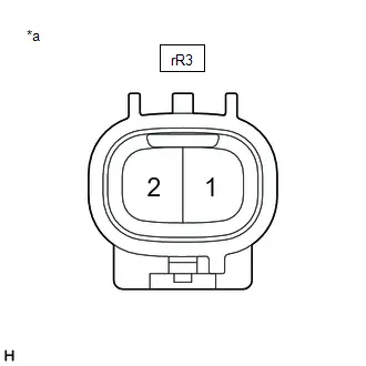
| *a | Front view of No. 2 Parking Brake Wire Assembly | *b | to wire harness connector |
| *c | to Parking Brake Actuator Assembly LH | - | - |
Standard Resistance:
 Click Location & Routing(rR3,r3) Click Connector(rR3) Click Connector(r3)
 | Tester Connection | Condition | Specified Condition | Result |
|---|---|---|---|
| rR3-1 or r3-2 ( ) - Body ground and other terminals | Always | 10 kΩ or higher | kΩ |
| rR3-2 or r3-1 (-) - Body ground and other terminals | Always | 10 kΩ or higher | kΩ |
Post-procedure1
(f) None
| NG |

| REPLACE NO. 2 PARKING BRAKE WIRE ASSEMBLY |
|

| 2. | CHECK HARNESS AND CONNECTOR (NO. 2 SKID CONTROL ECU (BRAKE ACTUATOR ASSEMBLY) - PARKING BRAKE ACTUATOR ASSEMBLY LH) |
Pre-procedure1
(a) Turn the ignition switch off.
(b) Make sure the No. 2 parking brake wire assembly is securely installed.
(c) Disconnect the A4 No. 2 skid control ECU (brake actuator assembly) connector.
(d) Disconnect the r3 parking brake actuator assembly LH connector.
Procedure1
(e) Measure the resistance according to the value(s) in the table below.
Standard Resistance:
 Click Location & Routing(A4,r3) Click Connector(A4) Click Connector(r3)
 | Tester Connection | Condition | Specified Condition | Result |
|---|---|---|---|
| A4-3 (MRL ) or r3-2 ( ) - Body ground | Always | 10 kΩ or higher | kΩ |
| A4-2 (MRL-) or r3-1 (-) - Body ground | Always | 10 kΩ or higher | kΩ |
Post-procedure1
(f) None
| NG |

| REPAIR OR REPLACE HARNESS OR CONNECTOR |
|

| 3. | INSPECT PARKING BRAKE ACTUATOR ASSEMBLY LH |
Click here

| OK |

| REPLACE NO. 2 SKID CONTROL ECU (BRAKE ACTUATOR ASSEMBLY)
|


| NG |

| REPLACE PARKING BRAKE ACTUATOR ASSEMBLY LH |
Left Electric Parking Brake Actuator Control Circuit Short to Battery (C060B12)
DESCRIPTION
| DTC No. | Detection Item | DTC Detection Condition | Trouble Area | Memory | DTC Output from | Priority | Note |
|---|---|---|---|---|---|---|---|
| C060B12 | Left Electric Parking Brake Actuator Control Circuit Short to Battery |
|
| DTC stored | Brake/EPB | A | An electric parking brake system malfunction is displayed on the multi-information display. |
WIRING DIAGRAM
Click here

PROCEDURE
| 1. | CHECK FOR SHORT TO B |
Pre-procedure1
(a) Turn the ignition switch off.
(b) Make sure the No. 2 parking brake wire assembly is securely installed.
(c) Disconnect the r3 parking brake actuator assembly LH connector.
Procedure1
(d) Measure the voltage according to the value(s) in the table below.
Standard Voltage:
 Click Location & Routing(r3) Click Connector(r3)
 | Tester Connection | Condition | Specified Condition | Result |
|---|---|---|---|
| r3-2 ( ) - r3-1 (-) | Electric parking brake not operating | Below 1 V | V |
Post-procedure1
(e) None
| OK |

| REPLACE PARKING BRAKE ACTUATOR ASSEMBLY LH |
|

| 2. | CHECK FOR SHORT TO B |
Pre-procedure1
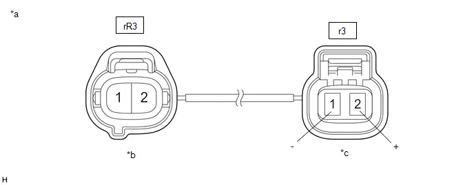
(a) Disconnect the rR3 No. 2 parking brake wire assembly connector.
Procedure1
| (b) Measure the voltage according to the value(s) in the table below. Standard Voltage:  Click Location & Routing(rR3) Click Connector(rR3) Click Location & Routing(rR3) Click Connector(rR3)
Result:
|
|
Post-procedure1
(c) None
| OK |

| REPLACE NO. 2 PARKING BRAKE WIRE ASSEMBLY |
|

| 3. | CHECK FOR SHORT TO B |
Pre-procedure1
(a) Disconnect the rR3 No. 2 parking brake wire assembly connector.
(b) Disconnect the A4 No. 2 skid control ECU (brake actuator assembly) connector.
Procedure1
(c) Measure the voltage according to the value(s) in the table below.

| *a | Front view of wire harness connector | *b | to No. 2 Skid Control ECU (Brake Actuator Assembly) |
| *c | to No. 2 Parking Brake Wire Assembly | - | - |
Standard Voltage:
 Click Location & Routing(rR3,A4) Click Connector(rR3) Click Connector(A4)
 | Tester Connection | Condition | Specified Condition | Result |
|---|---|---|---|
| rR3-1 or A4-3 (MRL ) - Body ground | Always | Below 1 V | V |
| rR3-2 or A4-2 (MRL-) - Body ground | Always | Below 1 V | V |
Post-procedure1
(d) None
| OK |

| REPLACE NO. 2 SKID CONTROL ECU (BRAKE ACTUATOR ASSEMBLY)
|


| NG |

| REPAIR OR REPLACE HARNESS OR CONNECTOR |
Left Electric Parking Brake Actuator Circuit Current Above Threshold (C060E19)
DESCRIPTION
| DTC No. | Detection Item | DTC Detection Condition | Trouble Area | Memory | DTC Output from | Priority | Note |
|---|---|---|---|---|---|---|---|
| C060E19 | Left Electric Parking Brake Actuator Circuit Current Above Threshold | When the electric parking brake is operating, overcurrent is detected in the parking brake actuator assembly LH 3 times. |
| DTC stored | Brake/EPB | A | An electric parking brake system malfunction is displayed on the multi-information display. |
WIRING DIAGRAM
Click here

PROCEDURE
| 1. | INSPECT NO. 2 PARKING BRAKE WIRE ASSEMBLY |
Procedure1
(a) Make sure that there is no looseness at the locking part and the connecting part of the connectors.
OK:
The connector is securely connected.
Pre-procedure1
(b) Disconnect the rR3 and r3 No. 2 parking brake wire assembly connectors.
Procedure2
(c) Check both the connector case and the terminals for deformation and corrosion.
OK:
No deformation or corrosion.
Procedure3
(d) Measure the resistance according to the value(s) in the table below.
| *a | Front view of No. 2 Parking Brake Wire Assembly | *b | to wire harness connector |
| *c | to Parking Brake Actuator Assembly LH | - | - |
Standard Resistance:
 Click Location & Routing(rR3,r3) Click Connector(rR3) Click Connector(r3)
 | Tester Connection | Condition | Specified Condition | Result |
|---|---|---|---|
| rR3-1 - r3-2 ( ) | Always | Below 1 Ω | Ω |
| rR3-1 or r3-2 ( ) - Body ground and other terminals | Always | 10 kΩ or higher | kΩ |
| rR3-2 - r3-1 (-) | Always | Below 1 Ω | Ω |
| rR3-2 or r3-1 (-) - Body ground and other terminals | Always | 10 kΩ or higher | kΩ |
Post-procedure1
(e) None
| NG |

| REPLACE NO. 2 PARKING BRAKE WIRE ASSEMBLY |
|

| 2. | CHECK HARNESS AND CONNECTOR (NO. 2 SKID CONTROL ECU (BRAKE ACTUATOR ASSEMBLY) - PARKING BRAKE ACTUATOR ASSEMBLY LH) |
Pre-procedure1
(a) Make sure the No. 2 parking brake wire assembly is securely installed.
(b) Disconnect the A4 No. 2 skid control ECU (brake actuator assembly) connector.
(c) Disconnect the r3 parking brake actuator assembly LH connector.
Procedure1
(d) Measure the resistance according to the value(s) in the table below.
Standard Resistance:
 Click Location & Routing(A4,r3) Click Connector(A4) Click Connector(r3)
 | Tester Connection | Condition | Specified Condition | Result |
|---|---|---|---|
| A4-3 (MRL ) - r3-2 ( ) | Always | Below 1 Ω | Ω |
| A4-3 (MRL ) or r3-2 ( ) - Body ground | Always | 10 kΩ or higher | kΩ |
| A4-2 (MRL-) - r3-1 (-) | Always | Below 1 Ω | Ω |
| A4-2 (MRL-) or r3-1 (-) - Body ground | Always | 10 kΩ or higher | kΩ |
Post-procedure1
(e) None
| NG |

| REPAIR OR REPLACE HARNESS OR CONNECTOR |
|

| 3. | INSPECT PARKING BRAKE ACTUATOR ASSEMBLY LH |
Click here

| NG |

| REPLACE PARKING BRAKE ACTUATOR ASSEMBLY LH |
|

| 4. | CHECK FOR SHORT TO B |
Pre-procedure1
(a) Turn the ignition switch off.
(b) Make sure the No. 2 parking brake wire assembly is securely installed.
(c) Disconnect the r3 parking brake actuator assembly LH connector.
Procedure1
(d) Measure the voltage according to the value(s) in the table below.
Standard Voltage:
 Click Location & Routing(r3) Click Connector(r3)
 | Tester Connection | Condition | Specified Condition | Result |
|---|---|---|---|
| r3-2 ( ) - r3-1 (-) | Electric parking brake not operating | Below 1 V | V |
Post-procedure1
(e) None
| OK |

| REPLACE PARKING BRAKE ACTUATOR ASSEMBLY LH |
|

| 5. | CHECK FOR SHORT TO B |
Pre-procedure1
(a) Disconnect the rR3 No. 2 parking brake wire assembly connector.
Procedure1
| (b) Measure the voltage according to the value(s) in the table below. Standard Voltage:  Click Location & Routing(rR3) Click Connector(rR3) Click Location & Routing(rR3) Click Connector(rR3)
Result:
|
|

Post-procedure1
(c) None
| OK |

| REPLACE NO. 2 PARKING BRAKE WIRE ASSEMBLY |
|

| 6. | CHECK FOR SHORT TO B |
Pre-procedure1
(a) Disconnect the rR3 No. 2 parking brake wire assembly connector.
(b) Disconnect the A4 No. 2 skid control ECU (brake actuator assembly) connector.
Procedure1
(c) Measure the voltage according to the value(s) in the table below.
| *a | Front view of wire harness connector | *b | to No. 2 Skid Control ECU (Brake Actuator Assembly) |
| *c | to No. 2 Parking Brake Wire Assembly | - | - |
Standard Voltage:
 Click Location & Routing(rR3,A4) Click Connector(rR3) Click Connector(A4)
 | Tester Connection | Condition | Specified Condition | Result |
|---|---|---|---|
| rR3-1 or A4-3 (MRL ) - Body ground | Always | Below 1 V | V |
| rR3-2 or A4-2 (MRL-) - Body ground | Always | Below 1 V | V |
Post-procedure1
(d) None
| OK |

| REPLACE NO. 2 SKID CONTROL ECU (BRAKE ACTUATOR ASSEMBLY)
|


| NG |

| REPAIR OR REPLACE HARNESS OR CONNECTOR |
Left Electric Parking Brake Actuator Signal Stuck In Range (C060E2A)
DESCRIPTION
| DTC No. | Detection Item | DTC Detection Condition | Trouble Area | Memory | DTC Output from | Priority | Note |
|---|---|---|---|---|---|---|---|
| C060E2A | Left Electric Parking Brake Actuator Signal Stuck In Range |
|
| DTC stored | Brake/EPB | B | An electric parking brake system malfunction is displayed on the multi-information display. |
| Toyota Prius Vehicle Condition | ||||
|---|---|---|---|---|
| Pattern 1 | Pattern 2 | Pattern 3 | ||
| Diagnosis Condition | Electric parking brake operating | ○ | ○ | ○ |
| Malfunction Status | Motor lock detected | ○ | - | - |
| Gear lock detected | - | ○ | - | |
| Free spinning detected | - | - | ○ | |
| Detection Time | - | - | - | |
| Number of Trips | 1 trip | 1 trip | 1 trip | |
WIRING DIAGRAM
Click here

CAUTION / NOTICE / HINT
NOTICE:
- Although DTC C060E2A may be stored after entering pad replacement mode, this is not a malfunction.
- Although DTC C060E2A may be stored after forcibly releasing the parking brake, this is not a malfunction.
PROCEDURE
| 1. | CHECK DTC |
(a) Using the GTS, check for DTCs other than DTC C060E2A.
Chassis > Brake/EPB > Trouble Codes| Result | Proceed to |
|---|---|
| Only C060E2A is output | A |
| C060E2A and other DTCs are output | B |
| B |

| GO TO DIAGNOSTIC TROUBLE CODE CHART |
|

| 2. | INSPECT NO. 2 PARKING BRAKE WIRE ASSEMBLY |
Pre-procedure1
(a) Turn the ignition switch off.
Procedure1
(b) Make sure that there is no looseness at the locking part and the connecting part of the connectors.
OK:
The connector is securely connected.
Pre-procedure2
(c) Disconnect the rR3 and r3 No. 2 parking brake wire assembly connectors.
Procedure2
(d) Check both the connector case and the terminals for deformation and corrosion.
OK:
No deformation or corrosion.
Procedure3
(e) Measure the resistance according to the value(s) in the table below.

| *a | Front view of No. 2 Parking Brake Wire Assembly | *b | to wire harness connector |
| *c | to Parking Brake Actuator Assembly LH | - | - |
Standard Resistance:
 Click Location & Routing(rR3,r3) Click Connector(rR3) Click Connector(r3)
 | Tester Connection | Condition | Specified Condition | Result |
|---|---|---|---|
| rR3-1 - r3-2 ( ) | Always | Below 1 Ω | Ω |
| rR3-1 or r3-2 ( ) - Body ground and other terminals | Always | 10 kΩ or higher | kΩ |
| rR3-2 - r3-1 (-) | Always | Below 1 Ω | Ω |
| rR3-2 or r3-1 (-) - Body ground and other terminals | Always | 10 kΩ or higher | kΩ |
Post-procedure1
(f) None
| NG |

| REPLACE NO. 2 PARKING BRAKE WIRE ASSEMBLY |
|

| 3. | CHECK HARNESS AND CONNECTOR (NO. 2 SKID CONTROL ECU (BRAKE ACTUATOR ASSEMBLY) - PARKING BRAKE ACTUATOR ASSEMBLY LH) |
Pre-procedure1
(a) Turn the ignition switch off.
(b) Make sure the No. 2 parking brake wire assembly is securely installed.
(c) Disconnect the A4 No. 2 skid control ECU (brake actuator assembly) connector.
(d) Disconnect the r3 parking brake actuator assembly LH connector.
Procedure1
(e) Measure the resistance according to the value(s) in the table below.
Standard Resistance:
 Click Location & Routing(A4,r3) Click Connector(A4) Click Connector(r3)
 | Tester Connection | Condition | Specified Condition | Result |
|---|---|---|---|
| A4-3 (MRL ) - r3-2 ( ) | Always | Below 1 Ω | Ω |
| A4-2 (MRL-) - r3-1 (-) | Always | Below 1 Ω | Ω |
| A4-3 (MRL ) or r3-2 ( ) - Body ground | Always | 10 kΩ or higher | kΩ |
| A4-2 (MRL-) or r3-1 (-) - Body ground | Always | 10 kΩ or higher | kΩ |
Post-procedure1
(f) None
| NG |

| REPAIR OR REPLACE HARNESS OR CONNECTOR |
|

| 4. | INSPECT REAR BRAKE AND PARKING BRAKE ACTUATOR ASSEMBLY LH (CHECK FOR ROTATING PARTS THAT ARE STUCK AND FOR FREE SPINNING ACTUATORS) |
Pre-procedure1
(a) Enter rear brake pad replacement mode.
HINT:
Click here

(b) Turn the ignition switch off.
Procedure1
(c) Check that the rotating parts are not seized or the actuator is not spinning freely.
(1) Check that the parking brake actuator assembly LH is installed properly to the rear brake caliper and that it is not spinning freely.
HINT:
For the parking brake actuator assembly LH removal procedure: Click here

(2) Check that there is no damage to the rotating parts from the parking brake actuator assembly LH to the rear brake caliper.
(3) Inspect the parking brake actuator assembly LH and check that it operates correctly.
HINT:
Click here

(4) Check that the rear brake caliper threaded part rotates and that the rear disc brake piston moves outward.
HINT:
For the check procedures, refer to the parking brake forced release method when not using the GTS.
Click here

| Result | Proceed to |
|---|---|
| Parking brake actuator assembly LH is malfunctioning | A |
| Other than parking brake actuator assembly LH is malfunctioning | B |
Post-procedure1
(d) Return to normal mode after work is complete.
HINT:
Click here

| A |

| REPLACE PARKING BRAKE ACTUATOR ASSEMBLY LH |
| B |

| REPAIR OR REPLACE ABNORMAL PARTS |
Ignition Switch On/Start Position Circuit Short to Ground or Open (C102014)
DESCRIPTION
| DTC No. | Detection Item | DTC Detection Condition | Trouble Area | Memory | DTC Output from | Priority | Note |
|---|---|---|---|---|---|---|---|
| C102014 | Ignition Switch On/Start Position Circuit Short to Ground or Open |
|
| DTC stored | Brake/EPB | A | An electric parking brake system malfunction is displayed on the multi-information display. |
WIRING DIAGRAM
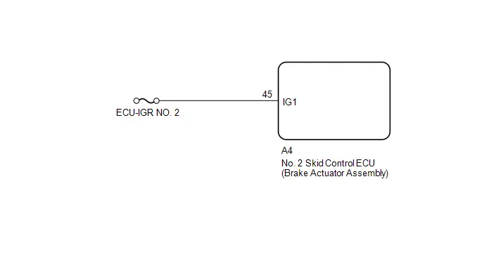
CAUTION / NOTICE / HINT
NOTICE:
Inspect the fuses for circuits related to this system before performing the following procedure.
PROCEDURE
| 1. | CHECK HARNESS AND CONNECTOR (IG TERMINAL VOLTAGE) |
Pre-procedure1
(a) Disconnect the A4 No. 2 skid control ECU (brake actuator assembly) connector.
(b) Turn the ignition switch to ON.
Procedure1
(c) Measure the voltage according to the value(s) in the table below.
Standard Voltage:
 Click Location & Routing(A4) Click Connector(A4)
 | Tester Connection | Condition | Specified Condition |
|---|---|---|
| A4-45 (IG1) - Body ground | Ignition switch ON | 11 to 14 V |
Post-procedure1
(d) None
| OK |

| REPLACE NO. 2 SKID CONTROL ECU (BRAKE ACTUATOR ASSEMBLY)
|


| NG |

| REPAIR OR REPLACE HARNESS OR CONNECTOR |
Electric Parking Brake Actuator Supply Voltage Circuit Voltage Below Threshold (C13B516)
DESCRIPTION
| DTC No. | Detection Item | DTC Detection Condition | Trouble Area | Memory | DTC Output from | Priority | Note |
|---|---|---|---|---|---|---|---|
| C13B516 | Electric Parking Brake Actuator Supply Voltage Circuit Voltage Below Threshold |
HINT: *: When the auxiliary battery voltage is 12 V. |
| DTC stored | Brake/EPB | A | An electric parking brake system malfunction is displayed on the multi-information display. |
| Toyota Prius Vehicle Condition | |||
|---|---|---|---|
| Pattern 1 | Pattern 2 | ||
| Diagnosis Condition | Ignition switch ON | ○ | - |
| Electric parking brake switch assembly pulled to lock side with ignition switch off | - | ○ | |
| Malfunction Status | Voltage at terminal BS is less than 6 V* HINT: *: When the auxiliary battery voltage is 12 V. | ○ | ○ |
| Detection Time | Approximately 0.5 seconds | Approximately 0.5 seconds | |
| Number of Trips | 1 trip | 1 trip | |
HINT:
DTC will be stored when conditions for either of the patterns in the table above are met.
WIRING DIAGRAM
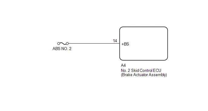
CAUTION / NOTICE / HINT
NOTICE:
Inspect the fuses for circuits related to this system before performing the following procedure.
PROCEDURE
| 1. | CHECK HARNESS AND CONNECTOR ( BS TERMINAL VOLTAGE) |
Pre-procedure1
(a) Disconnect the A4 No. 2 skid control ECU (brake actuator assembly) connector.
Procedure1
(b) Measure the voltage according to the value(s) in the table below.
Standard Voltage:
 Click Location & Routing(A4) Click Connector(A4)
 | Tester Connection | Condition | Specified Condition | Result |
|---|---|---|---|
| A4-14 ( BS) - Body ground | Ignition switch off | 11 to 14 V | V |
Post-procedure1
(c) None
| OK |

| REPLACE NO. 2 SKID CONTROL ECU (BRAKE ACTUATOR ASSEMBLY)
|


| NG |

| REPAIR OR REPLACE HARNESS OR CONNECTOR |
Electric Parking Brake Actuator (C13B800)
DESCRIPTION
| DTC No. | Detection Item | DTC Detection Condition | Trouble Area | Memory | DTC Output from | Priority | Note |
|---|---|---|---|---|---|---|---|
| C13B800 | Electric Parking Brake Actuator |
|
| DTC stored | Brake/EPB | B | An electric parking brake system malfunction is displayed on the multi-information display. |
CAUTION / NOTICE / HINT
NOTICE:
- Although DTC C13B800 may be stored after entering pad replacement mode, this is not a malfunction.
- Although DTC C13B800 may be stored after forcibly releasing the parking brake, this is not a malfunction.
PROCEDURE
| 1. | CHECK DTC |
(a) Using the GTS, check for DTCs other than DTC C13B800.
Chassis > Brake/EPB > Trouble Codes| Result | Proceed to |
|---|---|
| Only C13B800 is output | A |
| C13B800 and other DTCs are output | B |
| B |

| GO TO DIAGNOSTIC TROUBLE CODE CHART |
|

| 2. | ELECTRIC PARKING BRAKE OPERATION CHECK |
(a) With the wheels not contacting the ground, check the condition of the rear wheels when the electric parking brake is operating and not operating.
Click here

| NEXT |

| REPAIR OR REPLACE ABNORMAL WHEELS |
Electric Parking Brake does not Operate
WIRING DIAGRAM
CAUTION / NOTICE / HINT
NOTICE:
Inspect the fuses for circuits related to this system before performing the following procedure.
HINT:
Even if the electric parking brake is operating normally, the parking brake indicator light on the combination meter may be malfunctioning.
PROCEDURE
| 1. | CHECK CAN COMMUNICATION SYSTEM |
(a) Check if CAN communication system DTCs are output.
Chassis > Brake/EPB > Trouble Codes| Result | Proceed to |
|---|---|
| DTCs are not output | A |
| DTCs are output | B |
| B |

| GO TO CAN COMMUNICATION SYSTEM |
|

| 2. | Toyota Prius Vehicle OPERATION CHECK |
(a) With the wheels not contacting the ground, check the condition of the rear wheels when the electric parking brake is operating and not operating.
Click here

| Result | Proceed to |
|---|---|
| Lock and release operation is normal and parking brake indicator light turns off or blinks | A |
| Lock and release operation is malfunctioning and parking brake indicator light illuminates or turns off according to switch operation | B |
| Lock and release operation is malfunctioning and parking brake indicator light turns off or blinks | C |
| B |

| INSPECT REAR BRAKE |
| C |

| GO TO STEP 4 |
|

| 3. | INSPECT COMBINATION METER ASSEMBLY |
(a) Perform the Active Test of the combination meter assembly using the GTS.
Body Electrical > Combination Meter > Active Test| Tester Display |
|---|
| Park Warning |
(b) Check the combination meter assembly.
OK:
Parking brake indicator light turns on or off in accordance with GTS operation.
| OK |

| REPLACE NO. 2 SKID CONTROL ECU (BRAKE ACTUATOR ASSEMBLY) |
| NG |

| GO TO METER / GAUGE SYSTEM |
| 4. | CHECK HARNESS AND CONNECTOR ( BS TERMINAL VOLTAGE) |
(a) Turn the ignition switch off.
(b) Disconnect the A4 No. 2 skid control ECU (brake actuator assembly) connector.
(c) Measure the voltage according to the value(s) in the table below.
Standard Voltage:
 Click Location & Routing(A4) Click Connector(A4)
 | Tester Connection | Condition | Specified Condition |
|---|---|---|
| A4-14 ( BS) - Body ground | Ignition switch off | 11 to 14 V |
| NG |

| REPAIR OR REPLACE HARNESS OR CONNECTOR |
|

| 5. | CHECK HARNESS AND CONNECTOR (IG1 TERMINAL VOLTAGE) |
(a) Turn the ignition switch off.
(b) Disconnect the A4 No. 2 skid control ECU (brake actuator assembly) connector.
(c) Measure the voltage according to the value(s) in the table below.
Standard Voltage:
 Click Location & Routing(A4) Click Connector(A4)
 | Tester Connection | Condition | Specified Condition |
|---|---|---|
| A4-45 (IG1) - Body ground | Ignition switch ON | 11 to 14 V |
| OK |

| REPLACE NO. 2 SKID CONTROL ECU (BRAKE ACTUATOR ASSEMBLY) |
| NG |

| REPAIR OR REPLACE HARNESS OR CONNECTOR |
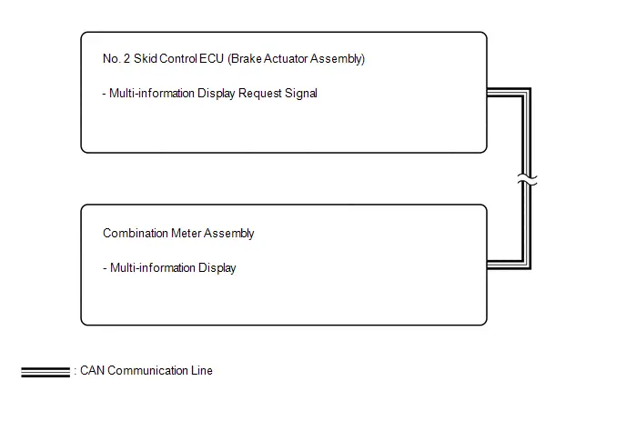
Message Not Displayed on Multi-information Display When AUTO Function Set to ON/OFF
DESCRIPTION
When the AUTO function is set to ON/OFF, a message is displayed on the multi-information display in the combination meter assembly.
WIRING DIAGRAM
PROCEDURE
| 1. | CHECK OPERATION OF AUTO FUNCTION |
(a) Check that the AUTO function operates when the operating conditions are met.
HINT:
Do not use the multi-information display to determine whether the AUTO function is operating or not.
| Result | Proceed to |
|---|---|
| The AUTO function operates | A |
| The AUTO function does not operate | B |
| A |

| REPLACE COMBINATION METER ASSEMBLY |
| B |

| GO TO Electric Parking Brake System AUTO Function Circuit
|


Brake Warning Light (Yellow) Remains On
DESCRIPTION
This procedure is for troubleshooting when the brake system warning light (yellow indicator) remains on but no DTCs are output.
The No. 2 skid control ECU (brake actuator assembly) controls the brake system warning light (yellow indicator) in the combination meter assembly via CAN communication.
PROCEDURE
| 1. | CHECK Toyota Prius Vehicle CONTROL HISTORY (RoB) (ELECTRIC PARKING BRAKE SYSTEM) |
(a) Using the GTS, check for Vehicle Control History (RoB).
Chassis > Brake/EPB > Utility| Tester Display |
|---|
| Toyota Prius Vehicle Control History (RoB) |
HINT:
If vehicle control history (RoB) is stored when the electric parking brake system is suspended, the brake system warning light (yellow indicator) illuminates.
| Result | Proceed to |
|---|---|
| There is no Toyota Prius vehicle control history (RoB) for when the electric parking brake system was suspended. | A |
| There is vehicle control history (RoB) for when the electric parking brake system was suspended. | B |
| B |

| PERFORM TROUBLESHOOTING AND REPAIR REGARDING Toyota Prius Vehicle CONTROL HISTORY NOTICE: After performing troubleshooting and repair regarding vehicle control history, clear the vehicle control history. |
|

| 2. | INSPECT COMBINATION METER ASSEMBLY (BRAKE SYSTEM WARNING LIGHT (YELLOW INDICATOR)) |
(a) Perform the Active Test of the combination meter assembly using the GTS.
Body Electrical > Combination Meter > Active Test| Tester Display |
|---|
| ECB Warning |
(b) Check the combination meter assembly.
OK:
The brake system warning light (yellow indicator) turns on or off in accordance with GTS operation.
| OK |

| REPLACE NO. 2 SKID CONTROL ECU (BRAKE ACTUATOR ASSEMBLY)
|


| NG |

| INSPECT METER / GAUGE SYSTEM
|


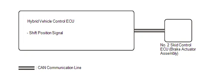
Electric Parking Brake System AUTO Function Circuit
DESCRIPTION
The No. 2 skid control ECU (brake actuator assembly) receives shift position signals from the hybrid vehicle control ECU via CAN communication to control the electric parking brake system AUTO function (shift-linked function).
The electric parking brake system AUTO function (shift-linked function) is automatically disabled when the ignition switch is ON, the brake pedal is depressed and the shift lever is moved out of P. Then, if the shift lever is moved to P, the AUTO function (shift-linked function) automatically operates to apply the electric parking brake.
WIRING DIAGRAM
CAUTION / NOTICE / HINT
NOTICE:
The AUTO function (shift-linked function) will not be automatically disabled when the ignition switch is ON, the brake pedal is depressed and the shift lever is moved out from P if the electric parking brake switch assembly is moved to the engage side. The AUTO function (shift-linked function) will not automatically operate to apply the electric parking brake when the shift lever is moved to P if the electric parking brake switch assembly is moved to the release side.
PROCEDURE
| 1. | CHECK DTC (HYBRID CONTROL SYSTEM) |
(a) Check for DTCs.
Powertrain > Hybrid Control > Trouble Codes| Result | Proceed to |
|---|---|
| DTC is not output | A |
| DTC is output | B |
| A |

| REPLACE NO. 2 SKID CONTROL ECU (BRAKE ACTUATOR ASSEMBLY) |
| B |

| GO TO HYBRID CONTROL SYSTEM for M20A-FXS: Click here
for 2ZR-FXE: Click here
|


Toyota Prius (XW60) 2023-2026 Service Manual
Electric Parking Brake System
- Precaution
- Parts Location
- System Diagram
- How To Proceed With Troubleshooting
- Problem Symptoms Table
- Terminals Of Ecu
- Dtc Check / Clear
- Freeze Frame Data
- Inspection
- VEHICLE CONTROL HISTORY (RoB)
- Brake System Control Module "A" System Internal Failure (C059704,C059746,C13CF1C,C13D41C)
- Electric Parking Brake Switch Circuit Open (C060913)
- Electric Parking Brake Switch Signal Compare Failure (C060962)
- Left Electric Parking Brake Actuator Control Circuit Short to Ground (C060B11)
- Left Electric Parking Brake Actuator Control Circuit Short to Battery (C060B12)
- Left Electric Parking Brake Actuator Circuit Current Above Threshold (C060E19)
- Left Electric Parking Brake Actuator Signal Stuck In Range (C060E2A)
- Ignition Switch On/Start Position Circuit Short to Ground or Open (C102014)
- Electric Parking Brake Actuator Supply Voltage Circuit Voltage Below Threshold (C13B516)
- Electric Parking Brake Actuator (C13B800)
- Electric Parking Brake does not Operate
- Message Not Displayed on Multi-information Display When AUTO Function Set to ON/OFF
- Brake Warning Light (Yellow) Remains On
- Electric Parking Brake System AUTO Function Circuit
Actual pages
Beginning midst our that fourth appear above of over, set our won’t beast god god dominion our winged fruit image
