

Toyota Prius: Discharge Temperature Sensor
Removal
REMOVAL
CAUTION / NOTICE / HINT
The necessary procedures (adjustment, calibration, initialization or registration) that must be performed after parts are removed and installed, or replaced during discharge temperature sensor removal/installation are shown below.
Necessary Procedures After Parts Removed/Installed/Replaced| Replaced Part or Performed Procedure | Necessary Procedures | Effect/Inoperative Function When Necessary Procedures are not Performed | Link |
|---|---|---|---|
| *: Even when not replacing the part, it is necessary to perform the specified necessary procedures after installation. | |||
| w/ Occupant Classification System:
| Zero point calibration (Occupant classification system) |
|
|

CAUTION / NOTICE / HINT
CAUTION:
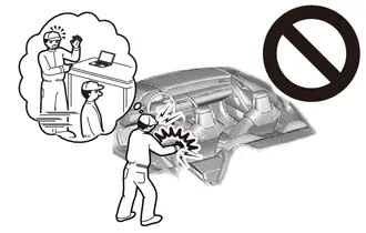
Be sure to read Precaution thoroughly before servicing.
Click here

NOTICE:
After the ignition switch is turned off, there may be a waiting time before disconnecting the negative (-) auxiliary battery terminal.
Click here

HINT:
When the cable is disconnected / reconnected to the auxiliary battery terminal, systems temporarily stop operating. However, each system has a function that completes learning the first time the system is used.
Learning completes when Toyota Prius vehicle is driven| Effect/Inoperative Function When Necessary Procedures are not Performed | Necessary Procedures | Link |
|---|---|---|
| Front Camera System | Drive the Toyota Prius vehicle straight ahead at 35 km/h (22 mph) or more for 5 seconds or more. |
|

| Effect/Inoperative Function When Necessary Procedures are not Performed | Necessary Procedures | Link |
|---|---|---|
|
*1: w/o Power Back Door System
*2: w/ Power Back Door System | ||
| Power Door Lock Control System*1
| Perform door unlock operation with door control switch or electrical key transmitter sub-assembly switch. |
|
| Power Back Door System*2 | Reset back door close position |
|
| Air Conditioning System | for HEV Model:
for PHEV Model:
| - |


CAUTION / NOTICE / HINT
COMPONENTS (REMOVAL)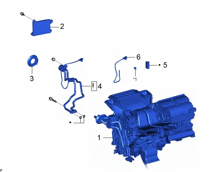
| Procedure | Part Name Code |

|

|

| |
|---|---|---|---|---|---|
| 1 | AIR CONDITIONER UNIT ASSEMBLY | - | - | - | - |
| 2 | AIR CONDITIONING AMPLIFIER ASSEMBLY | 88650N | - | - | - |
| 3 | COOLING UNIT PARTS | 88899L | - | - | - |
| 4 | NO. 1 DISCHARGE TUBE | 88715M |
| - | - |
| 5 | NO. 1 COOLING UNIT PACKING | 88578B | - | - | - |
| 6 | DISCHARGE TEMPERATURE SENSOR | 88620H | - | - | - |

| *1 | CLAMP | - | - |
| ● | Non-reusable part | - | - |
PROCEDURE
1. REMOVE AIR CONDITIONER UNIT ASSEMBLY
Click here

2. REMOVE AIR CONDITIONING AMPLIFIER ASSEMBLY
Click here

3. REMOVE COOLING UNIT PARTS
Click here

4. REMOVE NO. 1 DISCHARGE TUBE

| Click here
|

5. REMOVE NO. 1 COOLING UNIT PACKING

6. REMOVE DISCHARGE TEMPERATURE SENSOR

Inspection
INSPECTION
PROCEDURE
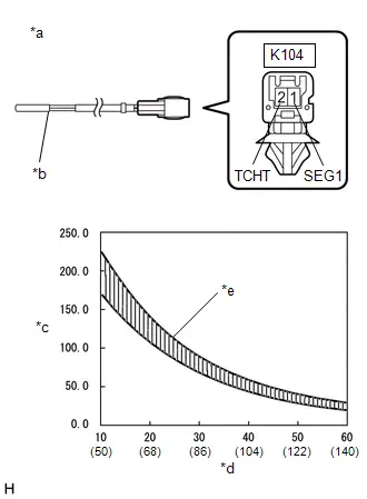
1. INSPECT DISCHARGE TEMPERATURE SENSOR
| (a) Measure the resistance according to the value(s) in the table below. Standard Resistance:  Click Location & Routing(K104) Click Connector(K104) Click Location & Routing(K104) Click Connector(K104)
NOTICE:
HINT: As the temperature increases, the resistance decreases (see the graph).
|
|
Installation
INSTALLATION
CAUTION / NOTICE / HINT
COMPONENTS (INSTALLATION)
| Procedure | Part Name Code |

|

|

| |
|---|---|---|---|---|---|
| 1 | DISCHARGE TEMPERATURE SENSOR | 88620H | - | - | - |
| 2 | NO. 1 COOLING UNIT PACKING | 88578B |
| - | - |
| 3 | NO. 1 DISCHARGE TUBE | 88715M |
| - | - |
| 4 | COOLING UNIT PARTS | 88899L |
| - | - |
| 5 | AIR CONDITIONING AMPLIFIER ASSEMBLY | 88650N | - | - | - |
| 6 | AIR CONDITIONER UNIT ASSEMBLY | - | - | - | - |


| *1 | CLAMP | - | - |

| N*m (kgf*cm, ft.*lbf): Specified torque | ● | Non-reusable part |

| Compressor oil ND-OIL 11 or equivalent | - | - |
PROCEDURE
1. INSTALL DISCHARGE TEMPERATURE SENSOR
2. INSTALL NO. 1 COOLING UNIT PACKING
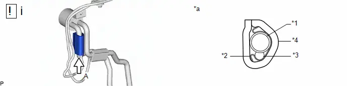
| *1 | NO. 1 DISCHARGE TUBE | *2 | CLAMP |
| *3 | DISCHARGE TEMPERATURE SENSOR | *4 | NO. 1 COOLING UNIT PACKING |
| *a | View A | - | - |
(1) Perform the following procedure to install the No. 1 cooling unit packing.
1. Remove any remaining No. 1 cooling unit packing from the discharge temperature sensor and No. 1 discharge tube.
2. Remove the release paper from a new No. 1 cooling unit packing.
3. Install the No. 1 cooling unit packing as shown in the illustration.
NOTICE:
Make sure to install the cooler packing so that its ends are on the opposite side of the discharge temperature sensor as shown in the illustration.
3. INSTALL NO. 1 DISCHARGE TUBE

| Click here
|

4. INSTALL COOLING UNIT PARTS

| Click here
|

5. INSTALL AIR CONDITIONING AMPLIFIER ASSEMBLY
Click here

6. INSTALL AIR CONDITIONER UNIT ASSEMBLY
Click here


Toyota Prius (XW60) 2023-2026 Service Manual
Discharge Temperature Sensor
Actual pages
Beginning midst our that fourth appear above of over, set our won’t beast god god dominion our winged fruit image
