

Toyota Prius: Digital Key System
- Precaution
- Parts Location
- System Diagram
- How To Proceed With Troubleshooting
- Check For Intermittent Problems
- Operation Check
- Registration
- Customize Parameters
- Problem Symptoms Table
- Terminals Of Ecu
- Data List / Active Test
- Diagnostic Trouble Code Chart
- Digital Key System Invalid/Incompatible Software Component (B27C057)
- Digital Key System Missing Message (B27C087)
- Driver Side BLE Antenna Missing Message (B27C387)
- Front Passenger Side BLE Antenna Missing Message (B27C487)
- Outside Luggage Compartment (Back Door) BLE Antenna Missing Message (B27C587)
- Front Floor BLE Antenna Missing Message (B27C687)
- Cannot Connect to BLE
- All Door Entry Lock/Unlock Functions and Wireless Functions do not Operate
- All Door Entry Lock/Unlock Functions do not Operate, but Wireless Functions Operate
- Driver Side Door Entry Lock and Unlock Functions do not Operate
- Front Passenger Side Door Entry Lock and Unlock Functions do not Operate
- Back Door Entry Lock and Unlock Functions do not Operate
- Driver Side Door Entry Lock/Unlock Operation Range has Decreased
- Front Passenger Side Door Entry Lock/Unlock Operation Range has Decreased
- Back Door Entry Lock/Unlock Operation Range has Decreased
- Power Source Mode does not Change (No Interior Verification)
- The Operation Range of the Power Source Switching Function has Decreased
- New Key cannot be Registered (Owner Key)
- Additional Key cannot be Registered (Share Key)
- Key Registration Message is not Displayed (Owner Key)
- Key Registration Message does not Disappear (Owner Key)
- Digital Key cannot be Cleared
- Digital Key cannot be Canceled
- Digital Key Battery Charge Low is not Displayed on the Multi-information Display
Precaution
PRECAUTION
PRECAUTIONS FOR DISCONNECTING CABLE FROM NEGATIVE (-) AUXILIARY BATTERY TERMINAL
NOTICE:
-
After the ignition switch is turned off, there may be a waiting time before disconnecting the negative (-) auxiliary battery terminal.
Click here

HINT:
When disconnecting and reconnecting the auxiliary battery, there is an automatic learning function that completes learning when the respective system is used.
Click here


PRECAUTIONS FOR DIGITAL KEY SYSTEM
(a) Before using the digital key system, refer to the owner's manual for the method of use and make sure to observe all precautions. The digital key system may not be able to be used in situations such as the following. In this case, it is recommended to carry the electrical key transmitter sub-assembly.
- When the smartphone is malfunctioning
- When the smartphone and server cannot communicate
- When the smartphone battery is depleted
- When the service is temporarily stopped due to maintenance, etc.
PRECAUTIONS FOR INSPECTION OR REGISTRATION
(a) If any of the following conditions are met, the digital key system cannot be used.
Furthermore, if an asterisk (*) is appended, the owner key cannot be registered.
- The digital key cannot communicate*
- The digital key battery is depleted*
- The telematics service cannot be used*
- There is no contract for the digital key service*
- The device is not a digital key compatible device.*
- Bluetooth function of the digital key is not set to ON.*
- The owner key is not registered
(b) If any of the following conditions are met, the digital key system may not be able to be used.
Furthermore, if an asterisk (*) is appended, the owner key may not be able to be registered.
- The digital key radio wave conditions are bad*
- The digital key application software is not the latest version*
- The digital key is displaying a message
- A share key function has been restricted from the owner key
- The service center is malfunctioning*
(c) In any of the following situations, the digital key system may not operate or the BLE connection range or operating range may be reduced depending on the radio wave environment.
-
There is a device that outputs strong radio waves or noise nearby.
(TV tower, electric power plant, broadcasting station, fuel station, airport, medical treatment facility, around a high voltage cable in an underpass or along a railway line or road, in the area of dense Wi-Fi router or Bluetooth device operation, in an area where a factory/Toyota Prius vehicle/equipment is using a wireless device, etc.)
- Parked in a pay parking facility
- The digital key is covered by a metal case, bag, etc.
-
The digital key is contacting an object that is metal, magnetic, etc.
(coins, wallet, IC card, point card, disposable heat packs, CDs, DVDs, etc.)
- A metallic film is applied to the rear window or pillars etc..
-
There is a device that outputs high-voltage or noise near the digital key
(wireless communication device, microwave oven, drone, electrical key transmitter sub-assembly or RF wireless remote control of another Toyota Prius vehicle, IH rice cooker, IH pot, machine tools, vacuum cleaner, washing machine, dryer, plasma TV, etc.)
-
When the digital key is near a device that is using Wi-Fi, Bluetooth, etc. communication
(Wi-Fi router, Wi-Fi or Bluetooth, etc. equipped household appliance, another mobile device, personal computer, tablet, digital audio player, portable game device, etc.)
- There is an electronic device that outputs high-voltage or noise inside or around the Toyota Prius vehicle.
- When the digital key is contacting an object that contains moisture (ice pack, PET bottle, water bottle, etc.)
(d) When diagnosing a vehicle at a dealer, all of the following items must be brought to the dealer by the customer.
- Electrical key transmitter sub-assembly
- Owner key
PRECAUTIONS FOR OUTSIDE Toyota Prius Vehicle DIGITAL KEY DETECTION RANGE/DIAGNOSTIC RANGE
(a) Driver door/front passenger door digital key detection range
(1) When locking/unlocking the door using the entry function, hold the digital key in your hand and hold your hand inside the detection range. Then operate the outside handle.
HINT:
- The range of the digital key detection area differs greatly depending on the type of digital key device, the way the device is held and the surrounding environment, etc.
- If operating near the edge of the Toyota Prius vehicle such as near the driver door glass or front passenger door glass, the entry function may not operate as the vehicle may be determining that the digital key is inside the vehicle.
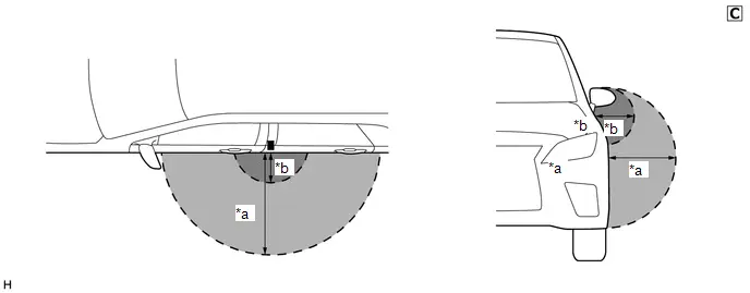
| *a | Digital Key Detection Range (approximately 70 - 100 cm (reference value measured using a typical device)) | *b | Digital Key Diagnostic Range (approximately 10 cm (reference value measured using a typical device)) |
The illustrations shown are examples only.
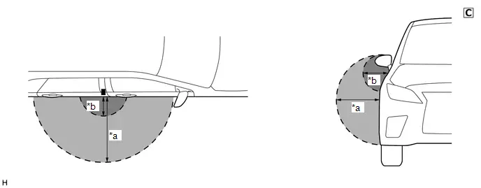
| *a | Digital Key Detection Range (approximately 70 - 100 cm (reference value measured using a typical device)) | *b | Digital Key Diagnostic Range (approximately 10 cm (reference value measured using a typical device)) |
The illustrations shown are examples only.
(b) Back door digital key detection range
When opening the back door using the entry function, hold the digital key in your hand and hold your hand inside the digital key detection range. Then operate the back door open switch. When locking the back door using the entry function, hold the digital key in your hand and hold your hand inside the digital key detection range. Then operate the back door lock switch.
HINT:
The range of the digital key detection area differs greatly depending on the type of digital key device, the way the device is held and the surrounding environment etc.
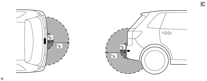
| *a | Digital Key Detection Range (approximately 70 - 100 cm (reference value measured using a typical device)) | *b | Digital Key Diagnostic Range (approximately 10 cm (reference value measured using a typical device)) |
The illustrations shown are examples only.
PRECAUTIONS FOR IN-Toyota Prius Vehicle OPERATING RANGE
(a) The in-vehicle operating range is above the center console near the vehicle interior BLE digital key receiver. When changing the power source mode to start the hybrid control system, etc., hold the digital key in the in-vehicle operating range.
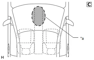
| *a | In-Toyota Prius vehicle Operating Range |
The illustrations shown are examples only.
PRECAUTIONS FOR POWER SAVING MODE
(a) If there are no vehicle operations for a certain amount of time, the vehicle enters power saving mode.
| Mode | Description |
|---|---|
| Power saving mode 1 | Start conditions
Power saving control
Power saving control
Power saving control stop conditions
|
| Power saving mode 2 | Start conditions
Power saving control
Power saving control
Power saving control stop conditions
|
| Power saving mode 3 | Start conditions
Power saving control
Power saving control stop conditions
|
PRECAUTION WHEN USING GTS
(a) When using the GTS with the ignition switch off, perform lock and unlock operations using the door control switch of the multiplex network master switch assembly at intervals of 1.5 seconds or less until communication between the GTS and the Toyota Prius vehicle begins, and then select the vehicle model manually.
Then select Model Code "KEY REGIST" under manual mode and enter the following menus: Body Electrical / Smart Key(CAN). While using the GTS, periodically perform lock and unlock operations using the door control switch of the multiplex network master switch assembly at intervals of 1.5 seconds or less to maintain communication between the GTS and the Toyota Prius vehicle.
(b) When connecting the GTS, the vehicle speed must be less than 5 km/h. If the vehicle speed is 5 km/h or more, the GTS and certification ECU cannot communicate.
PRECAUTION FOR REGISTRATION
(a) If replacing any of the following parts, refer to Registration.
Click here

(1) Certification ECU (smart key ECU assembly)
(2) Digital key ECU assembly
(3) BLE door digital key receiver assembly (for driver door)
(4) BLE door digital key receiver assembly (for front passenger door)
(5) BLE luggage digital key receiver assembly
(6) BLE indoor digital key receiver assembly
Parts Location
PARTS LOCATION
ILLUSTRATION
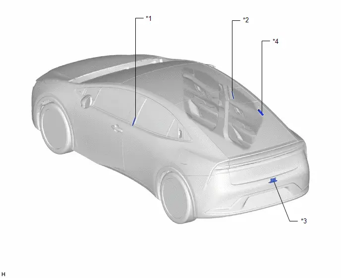
| *1 | BLE DOOR DIGITAL KEY RECEIVER ASSEMBLY (FOR DRIVER DOOR) | *2 | BLE DOOR DIGITAL KEY RECEIVER ASSEMBLY (FOR FRONT PASSENGER DOOR) |
| *3 | BLE LUGGAGE DIGITAL KEY RECEIVER ASSEMBLY | *4 | DIGITAL KEY ECU ASSEMBLY |
ILLUSTRATION
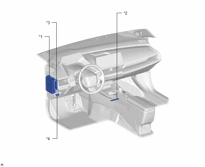
| *1 | POWER DISTRIBUTION BOX ASSEMBLY - ECU-DCC NO. 2 FUSE | *2 | BLE INDOOR DIGITAL KEY RECEIVER ASSEMBLY |
| *3 | CERTIFICATION ECU (SMART KEY ECU ASSEMBLY) | *4 | DLC3 |
System Diagram
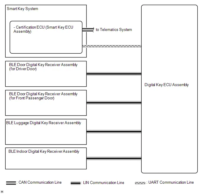
SYSTEM DIAGRAM
How To Proceed With Troubleshooting
CAUTION / NOTICE / HINT
NOTICE:
Make sure that the digital key system has not been disabled by a customize setting.
HINT:
- Replace parts related to digital key system according to the inspection procedure.
- If the digital key system does not operate, check the customize settings and make sure that the smart key system and digital key system are not disabled.
- If 2 or more digital keys are registered to the system, make sure to perform troubleshooting with all of them.
PROCEDURE
| 1. | Toyota Prius Vehicle BROUGHT TO WORKSHOP |
|

| 2. | PRE-CHECK |
(a) Confirm that inspection of cause of malfunction not related to Toyota Prius vehicle settings or vehicle components has been completed.
NOTICE:
With regards to the main cause of malfunctions not related to vehicle settings or vehicle components, refer to Precautions for Inspection or Registration before performing an inspection.
Click here

|

| 3. | CUSTOMER PROBLEM ANALYSIS |
HINT:
- In troubleshooting, confirm that the problem symptoms have been accurately identified. Preconceptions should be discarded in order to make an accurate judgment. To clearly understand what the problem symptoms are, it is extremely important to ask the customer about the problem and the conditions at the time the malfunction occurred.
- Gather as much information as possible for reference. Past malfunctions that seem unrelated may also help in some cases.
-
The following 5 items are important points for problem analysis:
What
Toyota Prius Vehicle model, system name
When
Date and time, frequency, whether the problem occurred recently or has been occurring for a long time
Where
Whether the problem occurs at specified location
Under what conditions?
Whether the doors were locked or unlocked, whether the ignition switch was ON, whether the hybrid control system was starting
How did it happen?
Ask the customer for details about the Toyota Prius vehicle operating conditions, environment and malfunction.
|

| 4. | READ AND SAVE Toyota Prius Vehicle CONTROL HISTORY (ROB) |
NOTICE:
- If the vehicle or vehicle controls are operated (for example, during initial inspection when the vehicle is brought in for repair) before vehicle control history (RoB) has been read and saved, the vehicle control vehicle control history (RoB) information could be lost.
- The Toyota Prius vehicle control vehicle control history (RoB) function uses the current system time of the GTS and the time counter inside the controlling ECU to calculate the times shown in the vehicle control vehicle control history (RoB). For this reason, before reading the vehicle control vehicle control history (RoB), first make sure that the GTS system clock is accurately set to the current time.
(a) Read and save Toyota Prius vehicle control history (RoB) using the GTS.
Body Electrical > Main Body > Utility| Tester Display |
|---|
| Vehicle Control History (RoB) |
|

| 5. | BASIC CHECK |
(a) Measure the auxiliary battery voltage with the ignition switch off.
Standard Voltage:
11 to 14 V
If the voltage is below 11 V, recharge or replace the auxiliary battery before proceeding to the next step.
(b) Check the fuses and relays.
(c) Check the connector connections and terminals to make sure that there are no abnormalities such as loose connections, deformation, etc.
|

| 6. | CHECK COMMUNICATION FUNCTION OF CAN COMMUNICATION SYSTEM* |
(a) Using the GTS, check for CAN communication system DTCs.
for PHV: Click here

for PHEV: Click here

| Result | Proceed to |
|---|---|
| CAN DTCs are not output | A |
| CAN DTCs are output | B |
| B |

| GO TO CAN COMMUNICATION SYSTEM for HEV: Click here
for PHEV: Click here
|


|

| 7. | CHECK COMMUNICATION FUNCTION OF LIN COMMUNICATION SYSTEM* |
(a) Using the GTS, check for LIN communication system DTCs.
Click here

| Result | Proceed to |
|---|---|
| LIN DTCs are not output | A |
| LIN DTCs are output | B |
| B |

| GO TO LIN COMMUNICATION SYSTEM |
|

| 8. | CHECK CUSTOMIZE ITEMS |
(a) Check that the digital key system and smart key system is set to on.
for Digital Key System: Click here

for Smart Key System (for Entry Function): Click here

for Smart Key System (for Start Function): Click here

HINT:
- If the digital key system is set to off, all functions of the digital key system will not function.
- If the smart key system is set to off, some functions of the digital key system will not function.
| Result | Proceed to |
|---|---|
| Digital key system and smart key system are enabled | A |
| Digital key system is disabled | B |
| Smart key system is disabled | C |
| B |

| GO TO CUSTOMIZE PARAMETERS |
| C |

| GO TO CUSTOMIZE PARAMETERS |
|

| 9. | CHECK FOR DTC* |
(a) Check for DTCs.
Body Electrical > Smart Key > Trouble Codes| Result | Proceed to |
|---|---|
| No DTCs are output | A |
| Smart key system or digital key system DTCs are output | B |
| DTCs other than smart key system and digital key system DTCs are output | C |
| B |

| GO TO DIAGNOSTIC TROUBLE CODE CHART for Smart Key System (for Entry Function): Click here
for Smart Key System (for Start Function): Click here
|


| C |

| GO TO DIAGNOSTIC TROUBLE CODE CHART |
|

| 10. | PROBLEM SYMPTOMS TABLE |
(a) Refer to Problem Symptoms Table.
Click here

| Result | Proceed to |
|---|---|
| Fault is not listed in Problem Symptoms Table (Fault can be simulated) | A |
| Fault is not listed in Problem Symptoms Table (Fault cannot be simulated) | B |
| Fault is listed in Problem Symptoms Table | C |
| B |

| CHECK FOR INTERMITTENT PROBLEMS |
| C |

| GO TO STEP 12 |
|

| 11. | OVERALL ANALYSIS AND TROUBLESHOOTING |
(a) Terminals of ECU
Click here

(b) Data List / Active Test
Click here

(c) Operation Check
Click here

|

| 12. | REPAIR OR REPLACE |
|

| 13. | CONFIRMATION TEST |
| NEXT |

| END |
Check For Intermittent Problems
CHECK FOR INTERMITTENT PROBLEMS
NOTICE:
- Operation history is stored in the RAM or EEPROM of the certification ECU (smart key ECU assembly). As the cause of a malfunction stored in the RAM will be cleared when the cable is disconnected from the negative (-) auxiliary battery terminal, do not disconnect the cable from the negative (-) auxiliary battery terminal before checking and recording are complete.
- If the Toyota Prius vehicle or vehicle controls are operated (for example, during initial inspection when the vehicle is brought in for repair) before operation history has been read and saved, the operation history information could be lost.
- The operation history function uses the current system time of the GTS and the time counter inside the controlling ECU to calculate the time shown in the operation history. For this reason, before reading the operation history, first make sure that the GTS system clock is accurately set to the current time.
Toyota Prius Vehicle CONTROL HISTORY (ROB)
HINT:
The certification ECU (smart key ECU assembly) stores the vehicle control history (RoB) of the smart key system and it can be read using the GTS.
(a) Read the Vehicle Control History (RoB) according to the display on the GTS.
Body Electrical > Smart Key > Utility| Tester Display |
|---|
| Toyota Prius Vehicle Control History (RoB) |
| Code | Item List | Item Description | Note |
|---|---|---|---|
| X0A18 | Auto Entry Wireless Operation History (Lock/Unlock) | Lock/unlock was performed by wireless operation. | - |
| X0A19 | Auto Entry Wireless Operation History (Open/Close) | Power slide door/back door was opened/closed by wireless operation. | - |
| X0A1A | Warning Operation History | Warning operation was performed by a function of the certification ECU. | - |
| X0A1B | Registration Function (Reason for Non-operation) | The reason that key registration failed. | - |
| X0A1F | Digital Key Control Change | Memory of digital key mode changing. | - |
| X0A26* | Digital Key (Inactive) | Memory of reason digital key function did not operate. | - |
HINT:
Some items may not be displayed depending on the specifications of the Toyota Prius vehicle.
- *: When "Digital Key (Inactive)" is stored, perform cause analysis in accordance with the following table.
| Main Category | Sub Category | Memorized Conditions | Suspected Cause |
|---|---|---|---|
| Digital Key (Inactive) |
| Digital key verification performed outside operating range | Digital key could not be detected within operating range
|
| Verification was performed even though no digital key movement was detected | The vibration sensor of the digital key may be disabled or malfunctioning
| |
| An operation that was restricted by the owner key was performed using the share key | An operation that was restricted by the owner key was performed using the share key
The valid period of the share key has expired
| |
| Digital key verification has failed | A normal signal cannot be received from the digital key due to noise, etc.
| |
| Verification was performed when the digital key was invalid | Digital key locked as it was detected that it was left inside the Toyota Prius vehicle
| |
| Digital key verification performed outside operating range | Due to some influence, digital key could not be detected
| |
| BLE digital key receiver communication malfunction occurred | Communication with the BLE digital key receiver was not possible
| |
| Verification of digital key was performed with no tokens left | Verification of digital key was performed with no tokens left as the number of uses was restricted by the owner key, etc.
|


SYMPTOM SIMULATION
Click here

Operation Check
OPERATION CHECK
CHECK CUSTOMIZE PARAMETERS
(a) The operation check below is based on the non-customized initial condition of the vehicle.
Digital Key System: Click here

Wireless Door Lock Control System: Click here

Smart Key System (for Entry Function): Click here

Smart Key System (for Start Function): Click here

CHECK WIRELESS FUNCTION
NOTICE:
- The wireless operation range may differ depending on the type of digital key device.
-
Refer to Precautions for Inspection or Registration regarding the digital key and surrounding environment.
Click here

HINT:
The following functions can be customized using the wireless door lock control system settings, and operate in the same way as the wireless door lock control system.
Click here

- Automatic locking function
- Answer-back function
- Door ajar warning buzzer function
- Wireless Unlock 2 Operation Function, etc.
(a) Approach the Toyota Prius vehicle and check that the establishment of a BLE connection is indicated on the digital key.
(b) When a BLE connection is established, check that all doors unlock when the unlock switch is pressed.
(c) When a BLE connection is established, check that all doors lock when the lock switch is pressed.
(d) When a BLE connection is established and the back door is unlocked, check that the back door opens when the back door open switch is pressed.
CHECK ENTRY FUNCTION
NOTICE:
-
Regarding the digital key detection range for the entry function, refer to Precautions for Outside Toyota Prius Vehicle Digital Key Detection Range/Diagnostic Range.
Click here

-
Refer to Precautions for Inspection or Registration regarding the digital key and surrounding environment.
Click here

HINT:
The following functions can be customized using the smart key system settings, and operate in the same way as the smart key system.
- Automatic locking function
- Answer-back function, etc.
(a) Check the entry unlock function (driver door, front passenger door).
(1) Lock all doors using the wireless function.
(2) With the digital key in your hand, hold your hand inside the digital key detection range and touch the unlock sensor built into the reverse side of the front door outside handle. Check that all doors unlock.
HINT:
Inspect the front passenger door using the same procedure.

| *a | Unlock Sensor (Backside) |
The illustrations shown are examples only.
(b) Check the entry lock function (driver door, front passenger door).
(1) Unlock all doors using the wireless function.
(2) With the digital key in your hand, hold your hand inside the digital key detection range and touch the lock sensor on the surface of the front door outside handle. Check that all doors lock.
HINT:
Inspect the front passenger door using the same procedure.

| *a | Lock Sensor |
The illustrations shown are examples only.
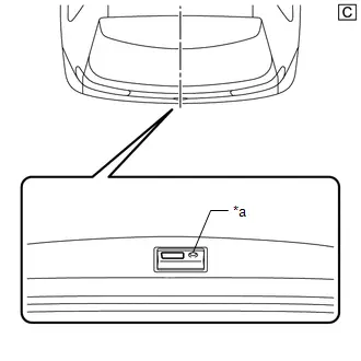
(c) Check the entry back door open function.
(1) With the back door closed and locked, hold the digital key in your hand and hold your hand inside the digital key detection range. Then operate the open switch.

| *a | Back Door Opener Switch Assembly (Open Switch) |
The illustrations shown are examples only.
(d) Check the entry back door lock function.
(1) With the back door closed and unlocked, hold the digital key in your hand and hold your hand inside the digital key detection range. Then operate the lock switch.
| *a | Back Door Opener Switch Assembly (Lock Switch) |
The illustrations shown are examples only.
CHECK POWER SOURCE MODE CHANGING FUNCTION
NOTICE:
-
Regarding the interior operating range, refer to Precautions for In-Toyota Prius vehicle Operating Range.
Click here

-
Refer to Precautions for Inspection or Registration regarding the digital key and surrounding environment.
Click here

(a) Unlock the doors by using the digital key.
(b) Place the digital key on the center console near the Toyota Prius vehicle interior BLE digital key receiver.
(c) When all of the following conditions are met, push the power switch and check that the hybrid control system starts.
- Ignition switch off*
- The shift state is P*
- The brake pedal is depressed*
HINT:
*: When the power switch is pushed when the conditions are not met, the power source mode will change the same as for the power source mode changing function of the smart key system.
Click here

DIGITAL KEY DIAGNOSTIC MODE (Using GTS)
NOTICE:
- With only one digital key connected to BLE, perform inspection in digital key diagnostic mode.
-
Regarding the digital key detection area outside the Toyota Prius vehicle cabin, refer to Precautions for Outside Vehicle Digital Key Detection Range/Diagnostic Range.
Click here

-
Regarding the interior operating range, refer to Precautions for In-vehicle Operating Range.
Click here

-
Refer to Precautions for Inspection or Registration regarding the digital key and surrounding environment.
Click here

HINT:
Whether the digital key operates correctly within the detection area can be confirmed when the wireless buzzer sounds with the system in digital key diagnostic mode.
(a) Enter the following menus: Body Electrical / Smart Key / Utility / Communication Check(Digital Key Diag Mode).
Body Electrical > Smart Key > Utility| Tester Display |
|---|
| Communication Check (Digital Key Diag Mode) |
(b) Inspect the appropriate item according to the following table.
| Tester Display | Inspection Item |
|---|---|
| Digital key engine/power start area [*1] | BLE indoor digital key receiver assembly |
| Digital key driver door outside area [*2] | BLE door digital key receiver assembly (for driver door) |
| Digital key passenger door outside area [*3] | BLE door digital key receiver assembly (for front passenger door) |
| Digital key back door/trunk lid outside area [*4] | BLE luggage digital key receiver assembly |
(c) Bring the digital key near the selected BLE digital key receiver and check that the wireless buzzer sounds.
(1) [*1]: BLE indoor digital key receiver assembly
HINT:
Place the digital key on the center console near the Toyota Prius vehicle interior BLE digital key receiver.
(2) [*2]: BLE door digital key receiver assembly (for driver door)
HINT:
Hold the digital key in your hand and hold your hand inside the driver door digital key detection range.
(3) [*3]: BLE door digital key receiver assembly (for front passenger door)
HINT:
Hold the digital key in your hand and hold your hand inside the front passenger door digital key detection range.
(4) [*4]: BLE luggage digital key receiver assembly
HINT:
Hold the digital key in your hand and hold your hand inside the back door digital key detection range.
Registration
REGISTRATION
PROCEDURE
1. CLEAR ALL DIGITAL KEYS USING MULTI-DISPLAY
NOTICE:
- Make sure to use the electrical key when turning the ignition switch to ON (IG) and clearing all the digital keys.
- If all digital keys are cleared, both the owner key and share keys are cleared.
HINT:
In this document, an electrical key refers to a registered electrical key transmitter sub-assembly.
| Procedure | Steps |
|---|---|
| 1. Start of erasure |
|
| 2. Confirmation of registered electrical keys |
|
| 3. End of erasure |
|
2. IMMOBILISER SYSTEM (KEY REGISTRATION)
HINT:

Customize Parameters
CUSTOMIZE PARAMETERS
CUSTOMIZE DIGITAL KEY SYSTEM
NOTICE:
-
Some functions of the digital key system can be customized using the customize settings of the wireless door lock control system. (auto lock time, answer back function ON/OFF, etc.)
Click here

-
Some functions of the digital key system can be customized using the customize settings of the smart key system. (smart key system ON/OFF, etc.)
for Smart Key System (for Entry Function): Click here

for Smart Key System (for Start Function): Click here

(a) Customizing with the GTS
(1) Connect the GTS to the DLC3.
(2) Turn the ignition switch to ON.
(3) Turn the GTS on.
(4) Enter the following menus: Customize Setting / Smart Key/Access
(5) Select the setting by referring to the table below.
Smart Key / Access| Tester Display | Description | Default | Setting | ECU |
|---|---|---|---|---|
| Auto Entry Function by Digital Key | Function that enables or disables the digital key system. | Normal | $00:Normal,$01:Cancel | Certification ECU (Smart key ECU assembly) |
(b) Customizing with the multi-display
NOTICE:
Customization of the digital key system can only be performed when the ignition switch is turned to ON using the electrical key transmitter sub-assembly.
(1) Turn the ignition switch to ON using the electrical key transmitter sub-assembly.
(2) Enter the following menus: Settings / Info & Security.
(3) Select the setting by referring to the table below.
| Display | Description | Default | Setting | ECU |
|---|---|---|---|---|
| Digital key system setting | Function that enables or disables the digital key system. | ON | ON/OFF | Certification ECU (Smart key ECU assembly) |
Problem Symptoms Table
PROBLEM SYMPTOMS TABLE
NOTICE:
- If the problem occurs in certain locations or times of day, the possibility of wave interference is high.
- If a malfunction occurred after optional components were installed by the dealer, check if there is wave interference from the components.
-
Before performing troubleshooting for the Toyota Prius vehicle, refer to Precautions for Inspection and Registration to check that the cause of the malfunction is not related to vehicle settings or vehicle components.
Click here

-
If the digital key system has been disabled, enable the system before performing troubleshooting.
Click here

- Make sure that no DTCs are output. If any DTCs are output, proceed to Diagnostic Trouble Code Chart.
- *a: Symptoms where the customer's digital key is required in order to perform troubleshooting
- *b: Symptoms where troubleshooting is possible by additionally registering a share key in place of the customer's digital key
- *c: Symptoms where the electrical key transmitter sub-assembly is required in order to perform troubleshooting
| Symptom | *a | *b | *c | Suspected Area | Link |
| Cannot connect to BLE | - | ● | - | Digital key |
|
| Digital key ECU assembly | |||||
| All door entry lock/unlock functions and wireless functions do not operate | ● | - | ● | Check customize setting (GTS) |
|
| Smart key system (for entry function) | |||||
| Digital key | |||||
| Digital key ECU assembly | |||||
| Certification ECU (smart key ECU assembly) | |||||
| All door entry lock/unlock functions do not operate, but wireless functions operate | ● | - | ● | Smart key system (for entry function) |
|
| Digital key ECU assembly | |||||
| Certification ECU (smart key ECU assembly) | |||||
| Driver side door entry lock and unlock functions do not operate | - | ● | ● | Smart key system (for entry function) |
|
| BLE door digital key receiver assembly (for driver door) | |||||
| Digital key ECU assembly | |||||
| Front passenger side door entry lock and unlock functions do not operate | - | ● | ● | Smart key system (for entry function) |
|
| BLE door digital key receiver assembly (for front passenger door) | |||||
| Digital key ECU assembly | |||||
| Back door entry lock and unlock functions do not operate | - | ● | ● | Smart key system (for entry function) |
|
| BLE luggage digital key receiver assembly | |||||
| Digital key ECU assembly | |||||
| Driver side door entry lock/unlock operation range has decreased | ● | - | - | Digital key |
|
| Install the BLE indoor digital key receiver assembly to the standard location | |||||
| BLE indoor digital key receiver assembly | |||||
| Install the BLE door digital key receiver assembly (for driver door) to the standard location | |||||
| BLE door digital key receiver assembly (for driver door) | |||||
| Front passenger side door entry lock/unlock operation range has decreased | ● | - | - | Digital key |
|
| Install the BLE indoor digital key receiver assembly to the standard location | |||||
| BLE indoor digital key receiver assembly | |||||
| Install the BLE door digital key receiver assembly (for front passenger door) to the standard location | |||||
| BLE door digital key receiver assembly (for front passenger door) | |||||
| Back door entry lock/unlock operation range has decreased | ● | - | - | Digital key |
|
| Install the BLE luggage digital key receiver assembly to the standard location | |||||
| BLE luggage digital key receiver assembly | |||||
| Power source mode does not change (no interior verification) | ● | - | ● | Smart key system (for start function) |
|
| Digital key | |||||
| BLE indoor digital key receiver assembly | |||||
| Digital key ECU assembly | |||||
| Certification ECU (smart key ECU assembly) | |||||
| The operation range of the power source switching function has decreased | ● | - | - | Check customize setting (digital key) |
|
| Digital key | |||||
| Install the BLE indoor digital key receiver assembly to the standard location | |||||
| BLE indoor digital key receiver assembly | |||||
| New key cannot be registered (owner key) | ● | - | ● | Check registration status of owner key |
|
| Clear all registered digital keys | |||||
| Smart key system (for start function) | |||||
| Register new owner key (using GTS) | |||||
| Digital key ECU assembly | |||||
| Certification ECU (smart key ECU assembly) | |||||
| Additional key cannot be registered (share key) | ● | - | ● | Clear all registered share keys (Using digital key application) |
|
| Clear all registered share keys (Using GTS) | |||||
| Check registration date of owner key | |||||
| Digital key ECU assembly | |||||
| Key registration message is not displayed (owner key) | ● | - | ● | Confirm registration date of owner key |
|
| Certification ECU (smart key ECU assembly) | |||||
| Key registration message does not disappear (owner key) | ● | - | - | Confirm registration date of owner key |
|
| Certification ECU (smart key ECU assembly) | |||||
| Digital key cannot be cleared | ● | - | ● | Clear all registered digital keys |
|
| Digital key | |||||
| Check the navigation system | |||||
| Digital key ECU assembly | |||||
| Certification ECU (smart key ECU assembly) | |||||
| Digital key cannot be canceled | ● | - | ● | Check the navigation system |
|
| Digital key ECU assembly | |||||
| Certification ECU (smart key ECU assembly) | |||||
| Digital key battery charge low is not displayed on the multi-information display | ● | - | ● | Check customize setting (digital key) |
|
| Smart key system (for start function) | |||||
| Digital key | |||||
| Digital key ECU assembly | |||||
| Certification ECU (smart key ECU assembly) | |||||
| Entry unlock response is poor (it takes approximately 4 seconds between touching the outside handle and unlock) | - | - | ● | Cancel power saving mode |
|


Terminals Of Ecu
TERMINALS OF ECU
HINT:
Make sure to cancel power saving mode when measuring the standard values.
Click here

CERTIFICATION ECU (SMART KEY ECU ASSEMBLY)
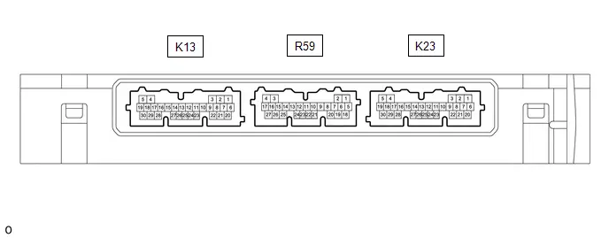
(a) Disconnect the K23 and K13 certification ECU (smart key ECU assembly) connectors.
(b) Measure the voltage and resistance according to the value(s) in the table below.
| Tester Connection | Terminal Description | Condition | Specified Condition |
|---|---|---|---|
| K13-6 ( B) - K13-29 (E) | Power source | Ignition switch off | 11 to 14 V |
| K23-22 (CUTB) - Body ground | Dark current cut pin* | Ignition switch off | 11 to 14 V |
| K13-29 (E) - Body ground | GND | Always | Below 1 Ω |
- *: In order to prevent the Toyota Prius vehicle auxiliary battery from being depleted when the vehicle is shipped long distances, a fuse that cuts unnecessary electrical load while the vehicle is being shipped is installed in the circuit. If the fuse is removed, the circuit becomes open. If the fuse that is between the vehicle auxiliary battery and terminal CUTB is removed and the circuit is open, the certification ECU (smart key ECU assembly) changes to a certain control mode (example: the transmission of radio waves every 0.25 seconds, which form the detection area, stops).
(c) Connect the K23 and K13 certification ECU (smart key ECU assembly) connectors.
(d) Measure the voltage according to the value(s) in the table below.
| Tester Connection | Terminal Description | Condition | Specified Condition |
|---|---|---|---|
| K13-17 (UAT2) - K13-29 (E) | UART communication line | All of the following conditions are met:
| 11 to 14 V |
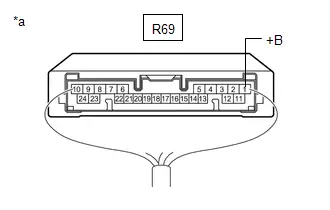
DIGITAL KEY ECU ASSEMBLY

(a) Disconnect the R69 Digital key ECU assembly connector.
(b) Measure the voltage and resistance according to the value(s) in the table below.
| Tester Connection | Terminal Description | Condition | Specified Condition |
|---|---|---|---|
| R69-1 ( B) - R69-10 (GND) | Power source | Ignition switch off | 11 to 14 V |
| R69-10 (GND) - Body ground | GND | Always | Below 1 Ω |
(c) Connect the R69 Digital key ECU assembly connector.
(d) Measure the voltage and check for pulses according to the value(s) in the table below.
| Tester Connection | Terminal Description | Condition | Specified Condition |
|---|---|---|---|
| R69-4 (PWI1) - R69-10 (GND) | BLE digital key receiver power source | Digital key is in BLE connection range. | 8.5 to 14 V |
| R69-12 (PWO1) - R69-10 (GND) | BLE digital key receiver power source | Digital key is in BLE connection range. | 8.5 to 14 V |
| R69-14 (LIN1) - R69-10 (GND) | LIN communication line | Digital key is in driver door digital key detection range. | Pulse generation |
| R69-15 (LIN2) - R69-10 (GND) | LIN communication line | Digital key is in front passenger door digital key detection range. | Pulse generation |
| R69-20 (LIN3) - R69-10 (GND) | LIN communication line | Digital key is in back door digital key detection range. | Pulse generation |
| R69-21 (LIN4) - R69-10 (GND) | LIN communication line | Digital key is in in-Toyota Prius vehicle operating range. | Pulse generation |
| R69-23 (UART) - R69-10 (GND) | UART communication line | All of the following conditions are met:
| Pulse generation (See waveform) |
(e) Using an oscilloscope, check the waveform of the ECU.
NOTICE:
The oscilloscope waveform shown in the illustration is an example for reference only. Noise, chattering, etc. are not shown.
(1) Waveform
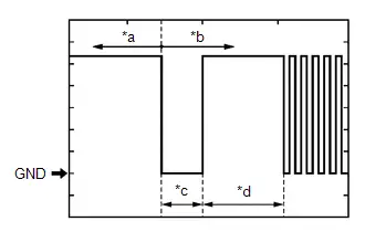
| *a | Before door lock/unlock operation using digital key |
| *b | After door lock/unlock operation using digital key |
| *c | Approximately 15 ms. |
| *d | 15 to 50 ms. |
| Item | Content |
|---|---|
| Tester Connection | R69-23 (UART) - R69-10 (GND) |
| Tool Setting | 2 V/DIV., 20 ms./DIV. |
| Condition | All of the following conditions are met:
|
Data List / Active Test
DATA LIST / ACTIVE TEST
DATA LIST
NOTICE:
When using the GTS with the ignition switch off, perform lock and unlock operations using the door control switch of the multiplex network master switch assembly at intervals of 1.5 seconds or less until communication between the GTS and the Toyota Prius vehicle begins, and then select the vehicle model manually.
Then select Model Code "KEY REGIST" under manual mode and enter the following menus: Body Electrical / Smart Access. While using the GTS, periodically perform lock and unlock operations using the door control switch of the multiplex network master switch assembly at intervals of 1.5 seconds or less to maintain communication between the GTS and the Toyota Prius vehicle.
(a) Connect the GTS to the DLC3.
(b) Turn the ignition switch to ON.
(c) Turn the GTS on.
(d) Enter the following menus: Body Electrical / Smart Key / Data List.
(e) Read the Data List according to the display on the GTS.
Body Electrical > Smart Key > Data List| Tester Display | Measurement Item | Range | Normal Condition | Diagnostic Note |
|---|---|---|---|---|
| Digital Key Registration/Erasure Status | Displays digital key registration or clearance status | Normal or Waiting | Normal: Registration or clearance not in progress Waiting: Registration or clearance in progress | - |
| Digital Key Registration/Erasure Error | Displays whether an error was detected during digital key registration or clearance | OFF or ON | OFF: No error detected ON: Error detected | - |
| D Code Registration Status | Displays completion of D code* registration on digital key ECU assembly | Normal or Finished | Normal: No registration operation Finished: Registration completed | - |
| D Code Registration Error | Displays whether an error was detected during D code* registration in the digital key ECU assembly | OFF or ON | OFF: No error detected ON: Error detected | - |
| Digital Key Wireless Request | Displays the operation contents when wireless operation is performed via digital key | None, Panic, Lock, Unlock, Trunk, PBW, PSD RH, PSD LH, PBD, or Pre A/C | None: No wireless operation Panic: Panic switch pushed Lock: Lock switch pushed Unlock: Unlock switch pushed Trunk: Luggage opener switch pushed PBW: Power back door window switch pushed PSD RH: Power slide door RH switch pushed PSD LH: Power slide door LH switch pushed PBD: Power back door switch pushed Pre A/C: Pre A/C switch pushed | - |
| Wireless Request Digital Key ID | Displays the digital key ID of the wireless operation | Guest2, Owner, Guest1(User1), Guest1(User2), Guest1(User3), Guest1(User4), Guest1(User5) or Guest1(User6) | Guest2: Share key 7 - 14 Owner: Owner key Guest1(User1): Share key 1 Guest1(User2): Share key 2 Guest1(User3): Share key 3 Guest1(User4): Share key 4 Guest1(User5): Share key 5 Guest1(User6): Share key 6 | - |
| Digital Key Collation Status | Displays the verification result between the BLE connected digital key and Toyota Prius vehicle | None, OK, NG or Collating | None: Not connected to BLE OK: Verification completed NG: Verification could not complete Collating: Verification in progress | - |
| Factor that cannot Collate Digital Key | Displays the reason when the verification result between the BLE connected digital key and Toyota Prius vehicle could not complete | None(Collation OK), Boundary Area, Key in Vehicle, No Motion, No Authority, Response NG, Invalid key, Not Connected, Out of Area, Error or Lost Crypton Token | None(Collation OK): Verification completed Boundary Area: Digital key verification was performed outside operating range Key in Toyota Prius Vehicle: Digital key detected in vehicle No Motion: Verification was performed when digital key was not detecting movement No Authority: Operation that was restricted from owner key was performed using share key Response NG: Signal from digital key could not be received correctly due to noise, etc. Invalid key: Verification was performed when the digital key was invalid Not Connected: Digital key not connected by BLE connection Out of Area: Digital key verification was performed outside operating range Error: Digital key system malfunction Lost Crypton Token: Verification of digital key was performed with no tokens left as the number of uses was restricted by the owner key, etc. | - |
| Digital Key ID 1 Collating Status | BLE connection status of digital key 1 | None or OK | None: Not connected OK: Connected | - |
| Digital Key ID 2 Collating Status | BLE connection status of digital key 2 | None or OK | None: Not connected OK: Connected | - |
| Digital Key ID 3 Collating Status | BLE connection status of digital key 3 | None or OK | None: Not connected OK: Connected | - |
| Digital Key ID 4 Collating Status | BLE connection status of digital key 4 | None or OK | None: Not connected OK: Connected | - |
| Digital Key ID 5 Collating Status | BLE connection status of digital key 5 | None or OK | None: Not connected OK: Connected | - |
| Digital Key ID 6 Collating Status | BLE connection status of digital key 6 | None or OK | None: Not connected OK: Connected | - |
| Digital Key ID 7 Collating Status | BLE connection status of digital key 7 | None or OK | None: Not connected OK: Connected | - |
| Digital Key Request Pattern | Request type from digital key | None, D Door Lock, P Door Lock, D Rear Door Lock, P Rear Door Lock, BD Lock, In Toyota Prius vehicle, In Trunk, All Key ID, PBD Close&Lock, D Door Unlock, P Door Unlock, D Rear Door Unlock, P Rear Door Unlock, BD Unlock, EG/Ready Start, In-lock Prevention 30s, In-lock Prevention Trunk or In-lock Prevention | None: No requested operation from digital key D Door Lock: Driver door lock request P Door Lock: Front passenger door lock request D Rear Door Lock: Rear door (driver seat side) lock request P Rear Door Lock: Rear door (front passenger seat side) lock request BD Lock: Back door lock request In Toyota Prius vehicle: Interior verification request In Trunk: Verification request in luggage compartment All Key ID: Request to acquire all digital key IDs for which vehicle interior verification has been completed PBD Close&Lock: Power back door close and lock request D Door Unlock: Driver door unlock request P Door Unlock: Front passenger door unlock request D Rear Door Unlock: Rear door (driver seat side) unlock request P Rear Door Unlock: Rear door (front passenger seat side) unlock request BD Unlock: Back door unlock request EG/Ready Start: Hybrid control system start request In-lock Prevention 30s: Lock out prevention 30 seconds request In-lock Prevention Trunk: Luggage compartment close request In-lock Prevention: Lock out prevention request | - |
| Digital Key ID 1 Plus Support Status | Displays status of digital key 1 plus support key settings | - | - | Although the item is displayed on the GTS, it is not applicable to this Toyota Prius vehicle. |
| Digital Key ID 2 Plus Support Status | Displays status of digital key 2 plus support key settings | - | - | Although the item is displayed on the GTS, it is not applicable to this Toyota Prius vehicle. |
| Digital Key ID 3 Plus Support Status | Displays status of digital key 3 plus support key settings | - | - | Although the item is displayed on the GTS, it is not applicable to this Toyota Prius vehicle. |
| Digital Key ID 4 Plus Support Status | Displays status of digital key 4 plus support key settings | - | - | Although the item is displayed on the GTS, it is not applicable to this Toyota Prius vehicle. |
| Digital Key ID 5 Plus Support Status | Displays status of digital key 5 plus support key settings | - | - | Although the item is displayed on the GTS, it is not applicable to this Toyota Prius vehicle. |
| Digital Key ID 6 Plus Support Status | Displays status of digital key 6 plus support key settings | - | - | Although the item is displayed on the GTS, it is not applicable to this Toyota Prius vehicle. |
| Digital Key ID 7 Plus Support Status | Displays status of digital key 7 plus support key settings | - | - | Although the item is displayed on the GTS, it is not applicable to this Toyota Prius vehicle. |
| Number of Connecting Digital keys | Displays number of digital keys connected to BLE | 0, 1, 2, 3, 4 or Over 5 | 0: No digital keys connected to BLE 1: 1 detected 2: 2 detected 3: 3 detected 4: 4 detected Over 5: 5 or more detected | - |
| Owner's Digital Key Registration Status | Registration status of owner key | Not Registered or Registered | Not Registered: Not registered Registered: Registered | |
| BLE Serial No.1 | Displays the No. 1 serial number of the digital key ECU assembly | - | - | - |
| BLE Serial No.2 | Displays the No. 2 serial number of the digital key ECU assembly | - | - | - |
| BLE Serial No.3 | Displays the No. 3 serial number of the digital key ECU assembly | - | - | - |
| BLE Serial No.4 | Displays the No. 4 serial number of the digital key ECU assembly | - | - | - |
| Digital Key's Antenna (LIN1) Status | Displays the connection status between the digital key and the driver seat exterior BLE antenna | Not Connected or Connected | Not Connected: Not connected Connected: Connected | - |
| Digital Key's Antenna (LIN2) Status | Displays the connection status between the digital key and the front passenger seat exterior BLE antenna | Not Connected or Connected | Not Connected: Not connected Connected: Connected | - |
| Digital Key's Antenna (LIN3) Status | Displays the connection status between the digital key and the luggage compartment exterior BLE antenna | Not Connected or Connected | Not Connected: Not connected Connected: Connected | - |
| Digital Key's Antenna (LIN4) Status | Displays the connection status between the digital key and the front seat interior BLE antenna | Not Connected or Connected | Not Connected: Not connected Connected: Connected | - |
| Digital Key's Antenna (LIN5) Status | Displays the connection status between the digital key and the rear seat interior BLE antenna | Not Connected or Connected | Not Connected: Not connected Connected: Connected | Although the item is displayed on the GTS, it is not applicable to this Toyota Prius vehicle. |
| Digital Key's Antenna (LIN6) Status | Displays the connection status between the digital key and the luggage compartment interior BLE antenna | Not Connected or Connected | Not Connected: Not connected Connected: Connected | Although the item is displayed on the GTS, it is not applicable to this Toyota Prius vehicle. |
| Number of Registered Key Codes (BLE) | Displays the number of registered digital keys | 0, 1, 2, 3, 4, 5, 6 or 7 | Number of registered digital keys | - |
| Factor that cannot Register Digital Key | Displays the reason when owner key registration failed | None, BLE Not Connected, Message Error, Write Error(Reg), Write Error(Res) or Reset Error | None: No registration operation BLE Not Connected: BLE connection could not be established Message Error: Message could not be received correctly Write Error(Reg): Digital key/D code could not be written correctly Write Error(Res): D code could not be cleared correctly Reset Error: Digital key could not be cleared correctly | - |
| LIN1 Antenna Error (DS code Registration) | Displays whether an error was detected during DS code registration in the driver seat exterior BLE antenna | Normal or Error | Normal: No error detected Error: Error detected | - |
| LIN2 Antenna Error (DS code Registration) | Displays whether an error was detected during DS code registration in the front passenger seat exterior BLE antenna | Normal or Error | Normal: No error detected Error: Error detected | - |
| LIN3 Antenna Error (DS code Registration) | Displays whether an error was detected during DS code registration in the luggage compartment exterior BLE antenna | Normal or Error | Normal: No error detected Error: Error detected | - |
| LIN4 Antenna Error (DS code Registration) | Displays whether an error was detected during DS code registration in the front seat interior BLE antenna | Normal or Error | Normal: No error detected Error: Error detected | - |
| LIN5 Antenna Error (DS code Registration) | Displays whether an error was detected during DS code registration in the rear seat interior BLE antenna | Normal or Error | Normal: No error detected Error: Error detected | Although the item is displayed on the GTS, it is not applicable to this Toyota Prius vehicle. |
| LIN6 Antenna Error (DS code Registration) | Displays whether an error was detected during DS code registration in the luggage compartment interior BLE antenna | Normal or Error | Normal: No error detected Error: Error detected | Although the item is displayed on the GTS, it is not applicable to this Toyota Prius vehicle. |
| Auto Entry Function by Digital Key | Displays the digital key system ON/OFF setting | Enable or Disable | Customize setting displayed | - |
- *: Verification code between certification ECU (smart key ECU assembly) and digital key ECU assembly
Diagnostic Trouble Code Chart
DIAGNOSTIC TROUBLE CODE CHART
Digital Key System| DTC No. | Detection Item | DTC Output from | Priority | Link |
|---|---|---|---|---|
| B27C057 | Digital Key System Invalid/Incompatible Software Component | Smart Key | A |
|
| B27C087 | Digital Key System Missing Message | Smart Key | A |
|
| B27C387 | Driver Side BLE Antenna Missing Message | Smart Key | A |
|
| B27C487 | Front Passenger Side BLE Antenna Missing Message | Smart Key | A |
|
| B27C587 | Outside Luggage Compartment (Back Door) BLE Antenna Missing Message | Smart Key | A |
|
| B27C687 | Front Floor BLE Antenna Missing Message | Smart Key | A |
|


Digital Key System Invalid/Incompatible Software Component (B27C057)
DESCRIPTION
This DTC is output when 1 or more electrical key transmitter sub-assemblies are registered and MAC data mismatch was detected 10 times in succession from the digital key computer assembly.
| DTC No. | Detection Item | DTC Detection Condition | Trouble Area | DTC Output from | Priority | Note |
|---|---|---|---|---|---|---|
| B27C057 | Digital Key System Invalid/Incompatible Software Component | 1 or more electrical key transmitter sub-assemblies are registered and MAC data mismatch was detected 10 times in succession from the digital key ECU assembly |
| Smart Key | A | DTC Output Confirmation Operation:
|
| Vehicle Condition when Malfunction Detected | Fail-safe Operation when Malfunction Detected |
|---|---|
| Digital key system does not operate | - |
WIRING DIAGRAM

CAUTION / NOTICE / HINT
NOTICE:
-
Before replacing certification ECU (smart key ECU assembly) or digital key ECU assembly, refer to Registration.
Click here

- Inspect the fuses for circuits related to this system before performing the following procedure.
PROCEDURE
| 1. | CHECK HARNESS AND CONNECTOR (CERTIFICATION ECU (SMART KEY ECU ASSEMBLY) - DIGITAL KEY ECU ASSEMBLY) |
Pre-procedure1
(a) Disconnect the K13 certification ECU (smart key ECU assembly) connector.
(b) Disconnect the R69 digital key ECU assembly connector.
Procedure1
(c) Measure the resistance according to the value(s) in the table below.
Standard Resistance:
 Click Location & Routing(K13,R69) Click Connector(K13) Click Connector(R69)
 | Tester Connection | Condition | Specified Condition | Result |
|---|---|---|---|
| K13-17 (UAT2) - R69-23 (UART) | Always | Below 1 Ω | Ω |
| K13-17 (UAT2) or R69-23 (UART) - Other terminals and body ground | Always | 10 kΩ or higher | kΩ |
Post-procedure1
(d) Connect the K13 certification ECU (smart key ECU assembly) connector.
| NG |

| REPAIR OR REPLACE HARNESS OR CONNECTOR |
|

| 2. | CLEAR DTC |
(a) Clear the DTCs.
Body Electrical > Smart Key > Clear DTCs
|

| 3. | CHECK DTC |
(a) Check for DTCs.
Body Electrical > Smart Key > Trouble Codes| Result | Proceed to |
|---|---|
| B27C057 is not output | A |
| B27C057 is output | B |
| A |

| REPLACE DIGITAL KEY ECU ASSEMBLY
|


| B |

| REPLACE CERTIFICATION ECU (SMART KEY ECU ASSEMBLY)
|


Digital Key System Missing Message (B27C087)
DESCRIPTION
This DTC is output when response frames from the digital key ECU assembly were not received 7 times consecutively x 7 sets after UART communication was established.
| DTC No. | Detection Item | DTC Detection Condition | Trouble Area | DTC Output from | Priority | Note |
|---|---|---|---|---|---|---|
| B27C087 | Digital Key System Missing Message | Output when response frames from the digital key ECU assembly were not received 7 times consecutively x 7 sets after UART communication was established |
| Smart Key | A | DTC Output Confirmation Operation:
|
| Vehicle Condition when Malfunction Detected | Fail-safe Operation when Malfunction Detected |
|---|---|
| Digital key system does not operate | - |
WIRING DIAGRAM

CAUTION / NOTICE / HINT
NOTICE:
-
Before replacing certification ECU (smart key ECU assembly) or digital key ECU assembly, refer to Registration.
Click here

- Inspect the fuses for circuits related to this system before performing the following procedure.
PROCEDURE
| 1. | CHECK HARNESS AND CONNECTOR (DIGITAL KEY ECU ASSEMBLY - POWER SOURCE)) |
| (a) Measure the voltage according to the value(s) in the table below. Standard Voltage:  Click Location & Routing(R69) Click Connector(R69) Click Location & Routing(R69) Click Connector(R69)
Result:
|
|
| NG |

| REPAIR OR REPLACE HARNESS OR CONNECTOR |
|

| 2. | CHECK HARNESS AND CONNECTOR (CERTIFICATION ECU (SMART KEY ECU ASSEMBLY) - DIGITAL KEY ECU ASSEMBLY - BODY GROUND) |
Pre-procedure1
(a) Disconnect the K13 certification ECU (smart key ECU assembly) connector.
(b) Disconnect the R69 digital key ECU connector.
Procedure1
(c) Measure the resistance according to the value(s) in the table below.
Standard Resistance:
 Click Location & Routing(K13,R69) Click Connector(K13) Click Connector(R69)
 | Tester Connection | Condition | Specified Condition | Result |
|---|---|---|---|
| K13-17 (UAT2) - R69-23 (UART) | Always | Below 1 Ω | Ω |
| K13-17 (UAT2) or R69-23 (UART) - Other terminals and body ground | Always | 10 kΩ or higher | kΩ |
| R69-10 (GND) - Body ground | Always | Below 1 Ω | Ω |
Post-procedure1
(d) Connect the K13 certification ECU (smart key ECU assembly) connector.
| NG |

| REPAIR OR REPLACE HARNESS OR CONNECTOR |
|

| 3. | CLEAR DTC |
(a) Clear the DTCs.
Body Electrical > Smart Key > Clear DTCs
|

| 4. | CHECK DTC |
(a) Check for DTCs.
Body Electrical > Smart Key > Trouble Codes| Result | Proceed to |
|---|---|
| B27C087 is not output | A |
| B27C087 is output | B |
| A |

| REPLACE DIGITAL KEY ECU ASSEMBLY
|


| B |

| REPLACE CERTIFICATION ECU (SMART KEY ECU ASSEMBLY)
|


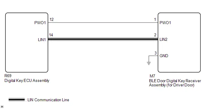
Driver Side BLE Antenna Missing Message (B27C387)
DESCRIPTION
This DTC is stored when a LIN communication malfunction between the digital key ECU assembly and BLE door digital key receiver assembly (for driver door) is detected.
| DTC No. | Detection Item | DTC Detection Condition | Trouble Area | DTC Output from | Priority | Note |
|---|---|---|---|---|---|---|
| B27C387 | Driver Side BLE Antenna Missing Message | LIN communication malfunction between the digital key ECU assembly and BLE door digital key receiver assembly (for driver door) |
| Smart Key | A | DTC Output Confirmation Operation:
|
| Vehicle Condition when Malfunction Detected | Fail-safe Operation when Malfunction Detected |
|---|---|
| Digital key is inside the driver seat digital key detection range
| - |
WIRING DIAGRAM
CAUTION / NOTICE / HINT
NOTICE:
-
Before replacing the digital key ECU assembly or BLE door digital key receiver assembly (for driver door), refer to Registration.
Click here

-
Cancel power saving mode before performing troubleshooting.
Click here

PROCEDURE
| 1. | CHECK CONNECTOR CONNECTION |
(a) Check that the connectors are properly connected to the digital key ECU assembly and BLE door digital key receiver assembly (for driver door).
OK:
Connectors are properly connected.
| NG |

| CONNECT CONNECTORS PROPERLY |
|

| 2. | CHECK HARNESS AND CONNECTOR (DIGITAL KEY ECU ASSEMBLY - BLE DOOR DIGITAL KEY RECEIVER ASSEMBLY (FOR DRIVER DOOR) - BODY GROUND) |
Pre-procedure1
(a) Disconnect the R69 digital key ECU assembly connector.
(b) Disconnect the M7 BLE door digital key receiver assembly (for driver door) connector.
Procedure1
(c) Measure the resistance according to the value(s) in the table below.
Standard Resistance:
 Click Location & Routing(R69,M7) Click Connector(R69) Click Connector(M7)
 | Tester Connection | Condition | Specified Condition | Result |
|---|---|---|---|
| R69-12 (PWO1) - M7-1 (PWO1) | Always | Below 1 Ω | Ω |
| R69-12 (PWO1) or M7-1 (PWO1) - Other terminals and body ground | Always | 10 kΩ or higher | kΩ |
| R69-14 (LIN1) - M7-2 (LIN2) | Always | Below 1 Ω | Ω |
| R69-14 (LIN1) or M7-2 (LIN2) - Other terminals and body ground | Always | 10 kΩ or higher | kΩ |
| M7-3 (GND) - Body ground | Always | Below 1 Ω | Ω |
Post-procedure1
(d) Connect the R69 digital key ECU assembly connector.
| NG |

| REPAIR OR REPLACE HARNESS OR CONNECTOR |
|

| 3. | REPLACE BLE DOOR DIGITAL KEY RECEIVER ASSEMBLY (FOR DRIVER DOOR) |
(a) Replace the BLE door digital key receiver assembly (for driver door) with a new one or used one.
HINT:
Click here


|

| 4. | CLEAR DTC |
(a) Clear the DTCs.
Body Electrical > Smart Key > Clear DTCs
|

| 5. | CHECK DTC |
(a) Check for DTCs.
Body Electrical > Smart Key > Trouble Codes| Result | Proceed to |
|---|---|
| B27C387 is not output | A |
| B27C387 is output | B |
| A |

| END (BLE DOOR DIGITAL KEY RECEIVER ASSEMBLY (FOR DRIVER DOOR) WAS DEFECTIVE) |
| B |

| REPLACE DIGITAL KEY ECU ASSEMBLY
|


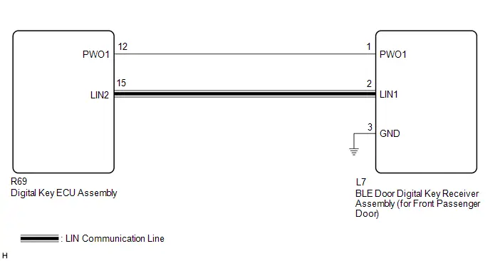
Front Passenger Side BLE Antenna Missing Message (B27C487)
DESCRIPTION
This DTC is stored when a LIN communication malfunction between the digital key ECU assembly and BLE door digital key receiver assembly (for front passenger door) is detected.
| DTC No. | Detection Item | DTC Detection Condition | Trouble Area | DTC Output from | Priority | Note |
|---|---|---|---|---|---|---|
| B27C487 | Front Passenger Side BLE Antenna Missing Message | LIN communication malfunction between the digital key ECU assembly and BLE door digital key receiver assembly (for front passenger door) |
| Smart Key | A | DTC Output Confirmation Operation:
|
| Vehicle Condition when Malfunction Detected | Fail-safe Operation when Malfunction Detected |
|---|---|
| Digital key is inside the front passenger seat digital key detection range
| - |
WIRING DIAGRAM
CAUTION / NOTICE / HINT
NOTICE:
-
Before replacing the digital key ECU assembly or BLE door digital key receiver assembly (for front passenger door), refer to Registration.
Click here

-
Cancel power saving mode before performing troubleshooting.
Click here

PROCEDURE
| 1. | CHECK CONNECTOR CONNECTION |
(a) Check that the connectors are properly connected to the digital key ECU assembly and BLE door digital key receiver assembly (for front passenger door).
OK:
Connectors are properly connected.
| NG |

| CONNECT CONNECTORS PROPERLY |
|

| 2. | CHECK HARNESS AND CONNECTOR (DIGITAL KEY ECU ASSEMBLY - BLE DOOR DIGITAL KEY RECEIVER ASSEMBLY (FOR FRONT PASSENGER DOOR) - BODY GROUND) |
Pre-procedure1
(a) Disconnect the R69 digital key ECU assembly connector.
(b) Disconnect the L7 BLE door digital key receiver assembly (for front passenger door) connector.
Procedure1
(c) Measure the resistance according to the value(s) in the table below.
Standard Resistance:
 Click Location & Routing(R69,L7) Click Connector(R69) Click Connector(L7)
 | Tester Connection | Condition | Specified Condition | Result |
|---|---|---|---|
| R69-12 (PWO1) - L7-1 (PWO1) | Always | Below 1 Ω | Ω |
| R69-12 (PWO1) or L7-1 (PWO1) - Other terminals and body ground | Always | 10 kΩ or higher | kΩ |
| R69-15 (LIN2) - L7-2 (LIN1) | Always | Below 1 Ω | Ω |
| R69-15 (LIN2) or L7-2 (LIN1) - Other terminals and body ground | Always | 10 kΩ or higher | kΩ |
| L7-3 (GND) - Body ground | Always | Below 1 Ω | Ω |
Post-procedure1
(d) Connect the R69 digital key ECU assembly connector.
| NG |

| REPAIR OR REPLACE HARNESS OR CONNECTOR |
|

| 3. | REPLACE BLE DOOR DIGITAL KEY RECEIVER ASSEMBLY (FOR FRONT PASSENGER DOOR) |
(a) Replace the BLE door digital key receiver assembly (for front passenger door) with a new one or used one.
HINT:
Click here


|

| 4. | CLEAR DTC |
(a) Clear the DTCs.
Body Electrical > Smart Key > Clear DTCs
|

| 5. | CHECK DTC |
(a) Check for DTCs.
Body Electrical > Smart Key > Trouble Codes| Result | Proceed to |
|---|---|
| B27C487 is not output | A |
| B27C487 is output | B |
| A |

| END (BLE DOOR DIGITAL KEY RECEIVER ASSEMBLY (FOR FRONT PASSENGER DOOR) WAS DEFECTIVE) |
| B |

| REPLACE DIGITAL KEY ECU ASSEMBLY
|


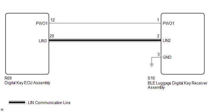
Outside Luggage Compartment (Back Door) BLE Antenna Missing Message (B27C587)
DESCRIPTION
This DTC is stored when a LIN communication malfunction between the digital key ECU assembly and BLE luggage digital key receiver assembly is detected.
| DTC No. | Detection Item | DTC Detection Condition | Trouble Area | DTC Output from | Priority | Note |
|---|---|---|---|---|---|---|
| B27C587 | Outside Luggage Compartment (Back Door) BLE Antenna Missing Message | LIN communication malfunction between the digital key ECU assembly and BLE luggage digital key receiver assembly |
| Smart Key | A | DTC Output Confirmation Operation:
|
| Vehicle Condition when Malfunction Detected | Fail-safe Operation when Malfunction Detected |
|---|---|
| Digital key is inside the back door digital key detection range
| - |
WIRING DIAGRAM
CAUTION / NOTICE / HINT
NOTICE:
-
Before replacing the digital key ECU assembly or BLE luggage digital key receiver assembly, refer to Registration.
Click here

-
Cancel power saving mode before performing troubleshooting.
Click here

PROCEDURE
| 1. | CHECK CONNECTOR CONNECTION |
(a) Check that the connectors are properly connected to the digital key ECU assembly and BLE luggage digital key receiver assembly.
OK:
Connectors are properly connected.
| NG |

| CONNECT CONNECTORS PROPERLY |
|

| 2. | CHECK HARNESS AND CONNECTOR (DIGITAL KEY ECU ASSEMBLY - BLE LUGGAGE DIGITAL KEY RECEIVER ASSEMBLY - BODY GROUND) |
Pre-procedure1
(a) Disconnect the R69 digital key ECU assembly connector.
(b) Disconnect the S10 BLE luggage digital key receiver assembly connector.
Procedure1
(c) Measure the resistance according to the value(s) in the table below.
Standard Resistance:
 Click Location & Routing(R69,S10) Click Connector(R69) Click Connector(S10)
 | Tester Connection | Condition | Specified Condition | Result |
|---|---|---|---|
| R69-12 (PWO1) - S10-1 (PWO1) | Always | Below 1 Ω | Ω |
| R69-12 (PWO1) or S10-1 (PWO1) - Other terminals and body ground | Always | 10 kΩ or higher | kΩ |
| R69-20 (LIN3) - S10-2 (LIN2) | Always | Below 1 Ω | Ω |
| R69-20 (LIN3) or S10-2 (LIN2) - Other terminals and body ground | Always | 10 kΩ or higher | kΩ |
| S10-3 (GND) - Body ground | Always | Below 1 Ω | Ω |
Post-procedure1
(d) Connect the R69 digital key ECU assembly connector.
| NG |

| REPAIR OR REPLACE HARNESS OR CONNECTOR |
|

| 3. | REPLACE BLE LUGGAGE DIGITAL KEY RECEIVER ASSEMBLY |
(a) Replace the BLE luggage digital key receiver assembly with a new one or used one.
HINT:
Click here


|

| 4. | CLEAR DTC |
(a) Clear the DTCs.
Body Electrical > Smart Key > Clear DTCs
|

| 5. | CHECK DTC |
(a) Check for DTCs.
Body Electrical > Smart Key > Trouble Codes| Result | Proceed to |
|---|---|
| B27C587 is not output | A |
| B27C587 is output | B |
| A |

| END (BLE LUGGAGE DIGITAL KEY RECEIVER ASSEMBLY WAS DEFECTIVE) |
| B |

| REPLACE DIGITAL KEY ECU ASSEMBLY
|


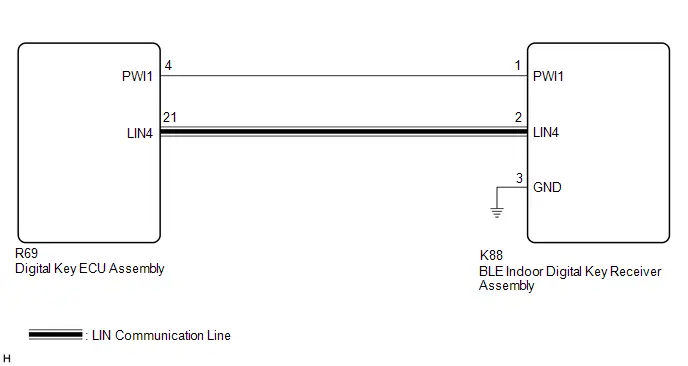
Front Floor BLE Antenna Missing Message (B27C687)
DESCRIPTION
This DTC is stored when a LIN communication malfunction between the digital key ECU assembly and BLE indoor digital key receiver assembly is detected.
| DTC No. | Detection Item | DTC Detection Condition | Trouble Area | DTC Output from | Priority | Note |
|---|---|---|---|---|---|---|
| B27C687 | Front Floor BLE Antenna Missing Message | LIN communication malfunction between the digital key ECU assembly and BLE indoor digital key receiver assembly |
| Smart Key | A | DTC Output Confirmation Operation:
|
| Vehicle Condition when Malfunction Detected | Fail-safe Operation when Malfunction Detected |
|---|---|
| The digital key is on the center console near the Toyota Prius vehicle interior BLE digital key receiver.
| - |
WIRING DIAGRAM
CAUTION / NOTICE / HINT
NOTICE:
-
Before replacing the digital key ECU assembly or BLE indoor digital key receiver assembly, refer to Registration.
Click here

-
Cancel power saving mode before performing troubleshooting.
Click here

PROCEDURE
| 1. | CHECK CONNECTOR CONNECTION |
(a) Check that the connectors are properly connected to the digital key ECU assembly and BLE indoor digital key receiver assembly.
OK:
Connectors are properly connected.
| NG |

| CONNECT CONNECTORS PROPERLY |
|

| 2. | CHECK HARNESS AND CONNECTOR (DIGITAL KEY ECU ASSEMBLY - BLE INDOOR DIGITAL KEY RECEIVER ASSEMBLY - BODY GROUND) |
Pre-procedure1
(a) Disconnect the R69 digital key ECU assembly connector.
(b) Disconnect the K88 BLE indoor digital key receiver assembly connector.
Procedure1
(c) Measure the resistance according to the value(s) in the table below.
Standard Resistance:
 Click Location & Routing(R69,K88) Click Connector(R69) Click Connector(K88)
 | Tester Connection | Condition | Specified Condition | Result |
|---|---|---|---|
| R69-4 (PWI1) - K88-1 (PWI1) | Always | Below 1 Ω | Ω |
| R69-4 (PWI1) or K88-1 (PWI1) - Other terminals and body ground | Always | 10 kΩ or higher | kΩ |
| R69-21 (LIN4) - K88-2 (LIN4) | Always | Below 1 Ω | Ω |
| R69-21 (LIN4) or K88-2 (LIN4) - Other terminals and body ground | Always | 10 kΩ or higher | kΩ |
| K88-3 (GND) - Body ground | Always | Below 1 Ω | Ω |
Post-procedure1
(d) Connect the R69 digital key ECU assembly connector.
| NG |

| REPAIR OR REPLACE HARNESS OR CONNECTOR |
|

| 3. | REPLACE BLE INDOOR DIGITAL KEY RECEIVER ASSEMBLY |
(a) Replace the BLE indoor digital key receiver assembly with a new one or used one.
HINT:
Click here


|

| 4. | CLEAR DTC |
(a) Clear the DTCs.
Body Electrical > Smart Key > Clear DTCs
|

| 5. | CHECK DTC |
(a) Check for DTCs.
Body Electrical > Smart Key > Trouble Codes| Result | Proceed to |
|---|---|
| B27C687 is not output | A |
| B27C687 is output | B |
| A |

| END (BLE INDOOR DIGITAL KEY RECEIVER ASSEMBLY WAS DEFECTIVE) |
| B |

| REPLACE DIGITAL KEY ECU ASSEMBLY
|


Cannot Connect to BLE
DESCRIPTION
When the digital key ECU assembly can connect to the digital key via the BLE connection, an indication of the successful BLE connection is displayed on the digital key screen. When a BLE connection cannot be established, it is not possible to perform vehicle operations that use the digital key.
CAUTION / NOTICE / HINT
NOTICE:
-
Before performing troubleshooting of the Toyota Prius vehicle, refer to Precautions for Inspection or Registration to check for a cause of the malfunction which is not related to vehicle settings or vehicle components.
Click here

- Perform troubleshooting with the electrical key transmitter sub-assembly not inside the detection area of the smart key system.
- Make sure that no DTCs are output. If any DTCs are output, proceed to Diagnostic Trouble Code Chart.
-
If the digital key system has been disabled, enable the system before performing troubleshooting.
Click here

-
Before replacing the digital key ECU assembly, refer to Registration.
Click here

PROCEDURE
| 1. | CHECK BLE CONNECTION |
(a) While near the Toyota Prius vehicle, check if the BLE connection is established using the digital key screen.
HINT:
The distance at which a BLE connection can be established may differ depending on the digital key device.
OK:
BLE connection can be established
| NG |

| GO TO STEP 3 |
|

| 2. | CAUSE ANALYSIS |
(a) Using the GTS, check for Toyota Prius Vehicle Control History (RoB).
Body Electrical > Smart Key > Utility| Tester Display |
|---|
| Vehicle Control History (RoB) |
(b) Perform cause analysis.
Click here

(c) Take appropriate action in accordance with the result of the cause analysis.
| NEXT |

| END |
| 3. | CHECK ANOTHER DIGITAL KEY |
(a) Check if there is digital key available that is already registered to the Toyota Prius vehicle.
| Result | Proceed to |
|---|---|
| Another registered digital key is not available | A |
| Another registered digital key is available | B |
| B |

| GO TO STEP 6 |
|

| 4. | CHECK USING ANOTHER Toyota Prius Vehicle |
(a) Check if another vehicle equipped with digital key system is available
| Result | Proceed to |
|---|---|
| Toyota Prius Vehicle equipped with digital key system not available | A |
| Vehicle equipped with digital key system available | B |
| B |

| GO TO STEP 7 |
|

| 5. | REGISTER NEW SHARE KEY |
(a) Register a share key.
HINT:
Refer to the digital key application.
|

| 6. | CHECK BLE CONNECTION |
(a) Using another registered digital key, check that a BLE connection can be established.
HINT:
The distance at which a BLE connection can be established may differ depending on the digital key device.
OK:
BLE connection can be established
| OK |

| END (PERFORM TROUBLESHOOTING ON ORIGINAL DIGITAL KEY) |
| NG |

| REPLACE DIGITAL KEY ECU ASSEMBLY
|


| 7. | REGISTER NEW SHARE KEY |
(a) Register the digital key with which a BLE connection could not be established to another Toyota Prius vehicle equipped with a digital key system as the share key.
HINT:
Refer to the digital key application.
|

| 8. | CHECK BLE CONNECTION |
(a) Using another Toyota Prius vehicle equipped with a digital key system, check that a BLE connection can be established.
HINT:
The distance at which a BLE connection can be established may differ depending on the digital key device.
OK:
BLE connection can be established
| OK |

| REPLACE DIGITAL KEY ECU ASSEMBLY
|


| NG |

| END (PERFORM TROUBLESHOOTING ON ORIGINAL DIGITAL KEY) |
All Door Entry Lock/Unlock Functions and Wireless Functions do not Operate
DESCRIPTION
When the digital key entry function and wireless function do not operate, there may be a malfunction in the communication system between the certification ECU (smart key ECU assembly) and digital key ECU assembly, or in the digital key.
WIRING DIAGRAM

CAUTION / NOTICE / HINT
NOTICE:
-
Before performing troubleshooting of the Toyota Prius vehicle, refer to Precautions for Inspection or Registration to check for a cause of the malfunction which is not related to vehicle settings or vehicle components.
Click here

- Perform troubleshooting with the electrical key transmitter sub-assembly not inside the detection area of the smart key system.
-
When using the digital key to perform door lock/unlock with the entry function, refer to Precautions for Outside Toyota Prius Vehicle Digital Key Detection Range/Diagnostic Range.
Click here

- Make sure that no DTCs are output. If any DTCs are output, proceed to Diagnostic Trouble Code Chart.
-
If the digital key system has been disabled, enable the system before performing troubleshooting.
Click here

- Inspect the fuses for circuits related to this system before performing the following procedure.
-
Cancel power saving mode before performing troubleshooting.
Click here

-
Before replacing the certification ECU (smart key ECU assembly) or digital key ECU assembly, refer to Registration.
Click here

PROCEDURE
| 1. | CHECK CUSTOMIZE SETTING USING GTS |
(a) Select the setting by referring to the table below.
Smart Key / Access| Tester Display | Description | Default | Setting | ECU |
|---|---|---|---|---|
| Auto Entry Cancel 2 Setting | Function that only prevents locking of the doors. | OFF | $00:OFF,$04:ON | Certification ECU (Smart key ECU assembly) |
| Result | Proceed to |
|---|---|
| Smart key system has not been canceled | A |
| Smart key system has been canceled | B |
| B |

| PERFORM CUSTOMIZE FUNCTION |
|

| 2. | CHECK SMART KEY SYSTEM (for Entry Function) |
(a) Check the smart key system (for entry function).
Click here

OK:
Smart key system (for Entry Function) operates properly
| NG |

| GO TO SMART KEY SYSTEM (for Entry Function) (HOW TO PROCEED WITH TROUBLESHOOTING) |
|

| 3. | CHECK BLE CONNECTION |
(a) While near the Toyota Prius vehicle, check if the BLE connection is established using the digital key screen.
HINT:
The distance at which a BLE connection can be established may differ depending on the digital key device.
OK:
BLE connection can be established
| NG |

| GO TO OTHER PROBLEM (Cannot Connect to BLE) |
|

| 4. | CHECK ENTRY FUNCTION AND WIRELESS FUNCTION (DRIVER DOOR / FRONT PASSENGER DOOR / BACK DOOR) |
(a) Check whether it is possible to use the digital key to perform door lock/unlock with the entry function.
(1) Check the entry unlock function (driver door, front passenger door).
- Turn the ignition switch off.
- Open and close the driver door.
- From outside the Toyota Prius vehicle, press the lock switch displayed on the digital key and lock all doors.
-
Hold the key in your hand and hold your hand inside the digital key detection range. Then grip the sensor on the reverse side of the door outside handle for 2 seconds or longer.*

*a
Unlock Sensor (Backside)
The illustrations shown are examples only.
-
*: Perform this step 3 seconds or more after performing step (3).
NOTICE:
-
For details on the digital key detection range, refer to Precautions for Outside Toyota Prius Vehicle Digital Key Detection Range/Diagnostic Range.
Click here

-
Refer to Precautions for Inspection or Registration regarding the digital key and surrounding environment.
Click here

HINT:
- When checking the operation of the unlock sensor again, make sure to perform the procedure from step (1).
- Inspect the front passenger door using the same procedure.
-
For details on the digital key detection range, refer to Precautions for Outside Toyota Prius Vehicle Digital Key Detection Range/Diagnostic Range.
-
*: Perform this step 3 seconds or more after performing step (3).
| (2) Check the entry lock function (driver door, front passenger door).
|
|


| (3) Check the entry back door open function.
|
|


| (4) Check the entry back door lock function.
NOTICE:
|
|


(b) Check the wireless function.
Click here

| Result | Proceed to |
|---|---|
| All door entry function and wireless function operate | A |
| All door entry function and wireless function do not operate | B |
| All door entry function does not operate, but wireless function operates | C |
| Entry function does not operate for one or more doors, but wireless function operates |
| B |

| GO TO STEP 6 |
| C |

| GO TO OTHER PROBLEM |
|

| 5. | CAUSE ANALYSIS |
(a) Using the GTS, check for Toyota Prius Vehicle Control History (RoB).
Body Electrical > Smart Key > Utility| Tester Display |
|---|
| Vehicle Control History (RoB) |
(b) Perform cause analysis.
Click here

(c) Take appropriate action in accordance with the result of the cause analysis.
| NEXT |

| END |
| 6. | CHECK ANOTHER DIGITAL KEY |
(a) Check if there is digital key available that is already registered to the Toyota Prius vehicle.
| Result | Proceed to |
|---|---|
| Another registered digital key is not available | A |
| Another registered digital key is available | B |
| B |

| GO TO STEP 9 |
|

| 7. | CHECK USING ANOTHER Toyota Prius Vehicle |
(a) Check if another vehicle equipped with digital key system is available
| Result | Proceed to |
|---|---|
| Toyota Prius Vehicle equipped with digital key system not available | A |
| Vehicle equipped with digital key system available | B |
| B |

| GO TO STEP 16 |
|

| 8. | REGISTER NEW SHARE KEY |
(a) Register a share key.
HINT:
Refer to the digital key application.
|

| 9. | CHECK ENTRY FUNCTION AND WIRELESS FUNCTION (DRIVER DOOR / FRONT PASSENGER DOOR / BACK DOOR) |
(a) Using another registered digital key, check whether the entry function and wireless function operate.
NOTICE:
For details on the digital key detection range, refer to Precautions for Outside Toyota Prius Vehicle Digital Key Detection Range/Diagnostic Range.
OK:
The entry function and wireless function operate
| OK |

| END (PERFORM TROUBLESHOOTING ON ORIGINAL DIGITAL KEY) |
|

| 10. | CHECK DIGITAL KEY ECU ASSEMBLY (TERMINAL UART) |
(a) Using an oscilloscope, check the waveform.

| *a | Component with harness connected (Digital Key ECU Assembly) | *b | Waveform |
| *c | Wakeup signal from digital key ECU assembly | *d | Approximately 15 ms. |
| *e | 15 to 50 ms. | *f | Before door lock/unlock operation using digital key |
| *g | After door lock/unlock operation using digital key | - | - |
NOTICE:
The waveform shown in the illustration is an example for reference only. Noise, chattering, etc. are not shown.
OK:
 Click Location & Routing(R69) Click Connector(R69)
 | Tester Connection | Condition | Tool Setting | Specified Condition |
|---|---|---|---|
| R69-23 (UART) - Body ground | All of the following conditions are met:
| 2 V/DIV., 20 ms./DIV. | Pulse generation (See waveform) |
| Result | Proceed to |
|---|---|
| OK (Normal Waveform) | A |
| NG (No Wakeup Signal) | B |
| NG (Normal Waveform Not Output) | C |
| NG (Stuck Low) | D |
| B |

| REPLACE DIGITAL KEY ECU ASSEMBLY
|


| C |

| REPLACE CERTIFICATION ECU (SMART KEY ECU ASSEMBLY)
|


| D |

| GO TO STEP 15 |
|

| 11. | REPLACE DIGITAL KEY ECU ASSEMBLY |
(a) Replace the digital key ECU assembly with a new one.
Click here


|

| 12. | REGISTER DIGITAL KEY CODE |
(a) Register the digital key code to the digital key ECU assembly.
Click here

|

| 13. | REGISTER NEW OWNER KEY |
(a) Register the owner key using the original digital key.
HINT:
Refer to the digital key application.
|

| 14. | CHECK ENTRY FUNCTION AND WIRELESS FUNCTION (DRIVER DOOR / FRONT PASSENGER DOOR / BACK DOOR) |
(a) Using the newly registered digital key, check that a wireless operation can be performed.
HINT:
- The wireless operation range may differ depends on the digital key device.
-
Refer to Precautions for Inspection or Registration regarding the digital key and surrounding environment.
Click here

OK:
The entry function and wireless function operate
| OK |

| END (DIGITAL KEY ECU ASSEMBLY WAS DEFECTIVE) |
| NG |

| REPLACE CERTIFICATION ECU (SMART KEY ECU ASSEMBLY)
|


| 15. | INSPECT CERTIFICATION ECU (SMART KEY ECU ASSEMBLY) |
(a) Disconnect the R69 digital key ECU assembly connector.
(b) Measure the voltage according to the value(s) in the table below.
Standard Voltage:
 Click Location & Routing(R69) Click Connector(R69)
 | Tester Connection | Condition | Specified Condition |
|---|---|---|
| R69-23 (UART) - Body ground | Ignition switch off | 11 to 14 V |
| OK |

| REPLACE DIGITAL KEY ECU ASSEMBLY
|


| NG |

| REPLACE CERTIFICATION ECU (SMART KEY ECU ASSEMBLY)
|


| 16. | REGISTER NEW SHARE KEY |
(a) Take a digital key where the entry function and wireless function do not operate, and register it as a share key of another Toyota Prius vehicle equipped with the digital key system.
HINT:
Refer to the digital key application.
|

| 17. | CHECK ENTRY FUNCTION AND WIRELESS FUNCTION (DRIVER DOOR / FRONT PASSENGER DOOR / BACK DOOR) |
(a) Using the other Toyota Prius vehicle equipped with the digital key system, check whether the entry function and wireless function operate.
NOTICE:
- For details on the digital key detection range, refer to Precautions for Outside Vehicle Digital Key Detection Range/Diagnostic Range.
- Refer to Precautions for Inspection or Registration regarding the digital key and surrounding environment.
OK:
The entry function and wireless function operate
| OK |

| GO TO STEP 10 |
| NG |

| END (PERFORM TROUBLESHOOTING ON ORIGINAL DIGITAL KEY) |
All Door Entry Lock/Unlock Functions do not Operate, but Wireless Functions Operate
DESCRIPTION
When the digital key entry function does not operate, there may be a malfunction in the communication system between the certification ECU (smart key ECU assembly) and digital key ECU assembly, or in the digital key.
WIRING DIAGRAM

CAUTION / NOTICE / HINT
NOTICE:
-
Before performing troubleshooting of the Toyota Prius vehicle, refer to Precautions for Inspection or Registration to check for a cause of the malfunction which is not related to vehicle settings or vehicle components.
Click here

- Perform troubleshooting with the electrical key transmitter sub-assembly not inside the detection area of the smart key system.
-
When using the digital key to perform door lock/unlock with the entry function, refer to Precautions for Outside Toyota Prius Vehicle Digital Key Detection Range/Diagnostic Range.
Click here

- Make sure that no DTCs are output. If any DTCs are output, proceed to Diagnostic Trouble Code Chart.
-
If the digital key system has been disabled, enable the system before performing troubleshooting.
Click here

- Inspect the fuses for circuits related to this system before performing the following procedure.
-
Cancel power saving mode before performing troubleshooting.
Click here

-
Before replacing the certification ECU (smart key ECU assembly) or digital key ECU assembly, refer to Registration.
Click here

PROCEDURE
| 1. | CHECK CUSTOMIZE SETTING USING GTS |
(a) Select the setting by referring to the table below.
Smart Key / Access| Tester Display | Description | Default | Setting | ECU |
|---|---|---|---|---|
| Auto Entry Cancel 2 Setting | Function that only prevents locking of the doors. | OFF | $00:OFF,$04:ON | Certification ECU (Smart key ECU assembly) |
| Result | Proceed to |
|---|---|
| Smart key system has not been canceled | A |
| Smart key system has been canceled | B |
| B |

| PERFORM CUSTOMIZE FUNCTION |
|

| 2. | CHECK SMART KEY SYSTEM (for Entry Function) |
(a) Check the smart key system (for entry function).
Click here

OK:
Smart key system (for Entry Function) operates properly
| NG |

| GO TO SMART KEY SYSTEM (for Entry Function) (HOW TO PROCEED WITH TROUBLESHOOTING) |
|

| 3. | CHECK ENTRY FUNCTION AND WIRELESS FUNCTION (DRIVER DOOR / FRONT PASSENGER DOOR / BACK DOOR) |
(a) Check whether it is possible to use the digital key to perform door lock/unlock with the entry function.
(1) Check the entry unlock function (driver door, front passenger door).
- Turn the ignition switch off.
- Open and close the driver door.
- From outside the Toyota Prius vehicle, press the lock switch displayed on the digital key and lock all doors.
-
Hold the key in your hand and hold your hand inside the digital key detection range. Then grip the sensor on the reverse side of the door outside handle for 2 seconds or longer.*

*a
Unlock Sensor (Backside)
The illustrations shown are examples only.
-
*: Perform this step 3 seconds or more after performing step (3).
NOTICE:
-
For details on the digital key detection range, refer to Precautions for Outside Toyota Prius Vehicle Digital Key Detection Range/Diagnostic Range.
Click here

-
Refer to Precautions for Inspection or Registration regarding the digital key and surrounding environment.
Click here

HINT:
- When checking the operation of the unlock sensor again, make sure to perform the procedure from step (1).
- Inspect the front passenger door using the same procedure.
-
For details on the digital key detection range, refer to Precautions for Outside Toyota Prius Vehicle Digital Key Detection Range/Diagnostic Range.
-
*: Perform this step 3 seconds or more after performing step (3).
| (2) Check the entry lock function (driver door, front passenger door).
|
|


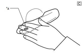
| (3) Check the entry back door open function.
|
|


| (4) Check the entry back door lock function.
NOTICE:
|
|


(5) Check the wireless function.
Click here

| Result | Proceed to |
|---|---|
| All door entry function and wireless function operate | A |
| All door entry function does not operate, but wireless function operates | B |
| All door entry function and wireless function do not operate | C |
| Entry function does not operate for one or more doors, but wireless function operates |
| B |

| GO TO STEP 5 |
| C |

| GO TO OTHER PROBLEM |
|

| 4. | CAUSE ANALYSIS |
(a) Using the GTS, check for Toyota Prius Vehicle Control History (RoB).
Body Electrical > Smart Key > Utility| Tester Display |
|---|
| Vehicle Control History (RoB) |
(b) Perform cause analysis.
Click here

(c) Take appropriate action in accordance with the result of the cause analysis.
| NEXT |

| END |
| 5. | CHECK DIGITAL KEY DIAGNOSTIC MODE (DRIVER DOOR / FRONT PASSENGER DOOR / BACK DOOR) |
NOTICE:
With only one digital key connected to BLE, perform inspection in digital key diagnostic mode.
(a) Check the BLE door digital key receiver assembly (for driver door) in digital key diagnostic mode.
(1) Using the GTS, select Body Electrical / Smart Key / Utility / Communication Check (Digital Key Diag Mode) / Digital key driver door outside area
Body Electrical > Smart Key > Utility| Tester Display |
|---|
| Communication Check (Digital Key Diag Mode) |
(2) Hold the digital key in your hand, and hold your hand inside the digital key detection range. Check that the wireless buzzer sounds.
NOTICE:
- For details on the digital key detection range, refer to Precautions for Outside Toyota Prius Vehicle Digital Key Detection Range/Diagnostic Range.
- Refer to Precautions for Inspection or Registration regarding the digital key and surrounding environment.
(b) Check the BLE door digital key receiver assembly (for front passenger door) in digital key diagnostic mode.
(1) Using the GTS, select Body Electrical / Smart Key / Utility / Communication Check (Digital Key Diag Mode) / Digital key passenger door outside area
Body Electrical > Smart Key > Utility| Tester Display |
|---|
| Communication Check (Digital Key Diag Mode) |
(2) Hold the digital key in your hand, and hold your hand inside the digital key detection range. Check that the wireless buzzer sounds.
NOTICE:
- For details on the digital key detection range, refer to Precautions for Outside Toyota Prius Vehicle Digital Key Detection Range/Diagnostic Range.
- Refer to Precautions for Inspection or Registration regarding the digital key and surrounding environment.
(c) Check the BLE luggage digital key receiver assembly in digital key diagnostic mode.
(1) Using the GTS, select Body Electrical / Smart Key / Utility / Communication Check (Digital Key Diag Mode) / Digital key back door/trunk lid outside area
Body Electrical > Smart Key > Utility| Tester Display |
|---|
| Communication Check (Digital Key Diag Mode) |
(2) Hold the digital key in your hand, and hold your hand inside the digital key detection range. Check that the wireless buzzer sounds.
NOTICE:
- For details on the digital key detection range, refer to Precautions for Outside Toyota Prius Vehicle Digital Key Detection Range/Diagnostic Range.
-
Refer to Precautions for Inspection or Registration regarding the digital key and surrounding environment.
Click here

| Result | Proceed to |
|---|---|
| Wireless buzzer sounds in all operation ranges | A |
| Wireless buzzer fails to sound in all operation ranges | B |
| Wireless buzzer does not sound in a particular operation range | C |
| A |

| REPLACE CERTIFICATION ECU (SMART KEY ECU ASSEMBLY)
|


| C |

| GO TO OTHER PROBLEM |
|

| 6. | CHECK ANOTHER DIGITAL KEY |
(a) Check if there is digital key available that is already registered to the Toyota Prius vehicle.
| Result | Proceed to |
|---|---|
| Another registered digital key is not available | A |
| Another registered digital key is available | B |
| B |

| GO TO STEP 9 |
|

| 7. | CHECK USING ANOTHER Toyota Prius Vehicle |
(a) Check if another vehicle equipped with digital key system is available
| Result | Proceed to |
|---|---|
| Toyota Prius Vehicle equipped with digital key system not available | A |
| Vehicle equipped with digital key system available | B |
| B |

| GO TO STEP 16 |
|

| 8. | REGISTER NEW SHARE KEY |
(a) Register a share key.
HINT:
Refer to the digital key application.
|

| 9. | CHECK ENTRY FUNCTION (DRIVER DOOR / FRONT PASSENGER DOOR / BACK DOOR) |
(a) Using another registered digital key, check whether the entry function operates.
NOTICE:
- For details on the digital key detection range, refer to Precautions for Outside Toyota Prius Vehicle Digital Key Detection Range/Diagnostic Range.
- Refer to Precautions for Inspection or Registration regarding the digital key and surrounding environment.
OK:
Entry function operates
| OK |

| END (PERFORM TROUBLESHOOTING ON ORIGINAL DIGITAL KEY) |
|

| 10. | CHECK DIGITAL KEY ECU ASSEMBLY (TERMINAL UART) |
(a) Using an oscilloscope, check the waveform.

| *a | Component with harness connected (Digital Key ECU Assembly) | *b | Waveform |
| *c | Wakeup signal from digital key ECU assembly | *d | Approximately 15 ms. |
| *e | 15 to 50 ms. | *f | Before door lock/unlock operation using digital key |
| *g | After door lock/unlock operation using digital key | - | - |
NOTICE:
The waveform shown in the illustration is an example for reference only. Noise, chattering, etc. are not shown.
OK:
 Click Location & Routing(R69) Click Connector(R69)
 | Tester Connection | Condition | Tool Setting | Specified Condition |
|---|---|---|---|
| R69-23 (UART) - Body ground | All of the following conditions are met:
| 2 V/DIV., 20 ms./DIV. | Pulse generation (See waveform) |
| Result | Proceed to |
|---|---|
| OK (Normal Waveform) | A |
| NG (No Wakeup Signal) | B |
| NG (Normal Waveform Not Output) | C |
| NG (Stuck Low) | D |
| B |

| REPLACE DIGITAL KEY ECU ASSEMBLY
|


| C |

| REPLACE CERTIFICATION ECU (SMART KEY ECU ASSEMBLY)
|


| D |

| GO TO STEP 15 |
|

| 11. | REPLACE DIGITAL KEY ECU ASSEMBLY |
(a) Replace the digital key ECU assembly with a new one.
Click here


|

| 12. | REGISTER DIGITAL KEY CODE |
(a) Register the digital key code to the digital key ECU assembly.
Click here

|

| 13. | REGISTER NEW OWNER KEY |
(a) Register the owner key using the original digital key.
HINT:
Refer to the digital key application.
|

| 14. | CHECK ENTRY FUNCTION (DRIVER DOOR / FRONT PASSENGER DOOR / BACK DOOR) |
(a) Using another registered digital key, check whether the entry function operates.
NOTICE:
- For details on the digital key detection range, refer to Precautions for Outside Toyota Prius Vehicle Digital Key Detection Range/Diagnostic Range.
- Refer to Precautions for Inspection or Registration regarding the digital key and surrounding environment.
OK:
Entry function operates
| OK |

| END (DIGITAL KEY ECU ASSEMBLY WAS DEFECTIVE) |
| NG |

| REPLACE CERTIFICATION ECU (SMART KEY ECU ASSEMBLY)
|


| 15. | INSPECT CERTIFICATION ECU (SMART KEY ECU ASSEMBLY) |
(a) Disconnect the R69 digital key ECU assembly connector.
(b) Measure the voltage according to the value(s) in the table below.
Standard Voltage:
 Click Location & Routing(R69) Click Connector(R69)
 | Tester Connection | Condition | Specified Condition |
|---|---|---|
| R69-23 (UART) - Body ground | Ignition switch off | 11 to 14 V |
| OK |

| REPLACE DIGITAL KEY ECU ASSEMBLY
|


| NG |

| REPLACE CERTIFICATION ECU (SMART KEY ECU ASSEMBLY)
|


| 16. | REGISTER NEW SHARE KEY |
(a) Take a digital key where the entry function does not operate, and register it as a share key of another Toyota Prius vehicle equipped with the digital key system.
HINT:
Refer to the digital key application.
|

| 17. | CHECK ENTRY FUNCTION (DRIVER DOOR / FRONT PASSENGER DOOR / BACK DOOR) |
(a) Using the other Toyota Prius vehicle equipped with the digital key system, check whether the entry function operates.
NOTICE:
For details on the digital key detection range, refer to Precautions for Outside Vehicle Digital Key Detection Range/Diagnostic Range.
OK:
The entry function operates
| OK |

| GO TO STEP 10 |
| NG |

| END (PERFORM TROUBLESHOOTING ON ORIGINAL DIGITAL KEY) |
Driver Side Door Entry Lock and Unlock Functions do not Operate
DESCRIPTION
Remove all causes of non-operation other than the vehicle components and vehicle settings. Under these conditions, if only driver door entry lock and unlock using the digital key are not possible, there may be a malfunction in the communication system between the digital key ECU assembly and BLE door digital key receiver assembly (for driver door), or a malfunction in the digital key ECU assembly and BLE door digital key receiver assembly (for driver door).
CAUTION / NOTICE / HINT
NOTICE:
-
Before performing troubleshooting of the Toyota Prius vehicle, refer to Precautions for Inspection or Registration to check for a cause of the malfunction which is not related to vehicle settings or vehicle components.
Click here

- Perform troubleshooting with the electrical key transmitter sub-assembly not inside the detection area of the smart key system.
-
When using the digital key to perform door lock/unlock with the entry function, refer to Precautions for Outside Toyota Prius Vehicle Digital Key Detection Range/Diagnostic Range.
Click here

- Make sure that no DTCs are output. If any DTCs are output, proceed to Diagnostic Trouble Code Chart.
-
Cancel power saving mode before performing troubleshooting.
Click here

-
If the digital key system has been disabled, enable the system before performing troubleshooting.
Click here

-
Before replacing the digital key ECU assembly or BLE door digital key receiver assembly (for driver door), refer to Registration.
Click here

PROCEDURE
| 1. | CHECK SMART KEY SYSTEM (for Entry Function) |
(a) Check the smart key system (for entry function).
Click here

OK:
Smart key system (for Entry Function) operates properly
| NG |

| GO TO SMART KEY SYSTEM (for Entry Function) (HOW TO PROCEED WITH TROUBLESHOOTING) |
|

| 2. | CHECK ENTRY FUNCTION (DRIVER DOOR) |
(a) Check whether it is possible to use the digital key to perform door lock/unlock with the entry function.
(1) Check the entry unlock function.
- Turn the ignition switch off.
- Open and close the driver door.
- From outside the Toyota Prius vehicle, press the lock switch displayed on the digital key and lock all doors.
-
Hold the key in your hand and hold your hand inside the digital key diagnostic range. Then grip the sensor on the reverse side of the door outside handle for 2 seconds or longer.*
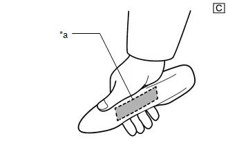
*a
Unlock Sensor (Backside)
The illustrations shown are examples only.
-
*: Perform this step 3 seconds or more after performing step (3).
NOTICE:
-
For details on the digital key diagnostic range, refer to Precautions for Outside Toyota Prius Vehicle Digital Key Detection Range/Diagnostic Range.
Click here

-
Refer to Precautions for Inspection or Registration regarding the digital key and surrounding environment.
Click here

HINT:
When checking the operation of the unlock sensor again, make sure to perform the procedure from step (1).
-
For details on the digital key diagnostic range, refer to Precautions for Outside Toyota Prius Vehicle Digital Key Detection Range/Diagnostic Range.
-
*: Perform this step 3 seconds or more after performing step (3).
(2) Check the entry lock function.
- Turn the ignition switch off.
- Open and close the driver door.
-
Hold the key in your hand and hold your hand inside the digital key diagnostic range. Then touch the lock sensor on the surface of the door outside handle (indentation on the door outside handle) with multiple fingers for 2 seconds or longer.
NOTICE:
-
For details on the digital key diagnostic range, refer to Precautions for Outside Toyota Prius Vehicle Digital Key Detection Range/Diagnostic Range.
Click here

-
Refer to Precautions for Inspection or Registration regarding the digital key and surrounding environment.
Click here

HINT:
- If the door does not lock even when touching the lock sensor for 2 seconds or more, touch it with your palm.
- When checking the operation of the lock sensor again, make sure to perform the procedure from step (1).
- When checking the operation of the entry lock function several times, it can be operated up to 2 times consecutively. To operate the function 3 times or more consecutively, the doors need to be unlocked once. However, this is only for the entry lock function, other door lock operations, such as a wireless door lock operation can be performed consecutively.

*a
Lock Sensor
The illustrations shown are examples only.
-
For details on the digital key diagnostic range, refer to Precautions for Outside Toyota Prius Vehicle Digital Key Detection Range/Diagnostic Range.
| Result | Proceed to |
|---|---|
| Entry function operates normally | A |
| Entry function does not operate normally | B |
| B |

| GO TO STEP 4 |
|

| 3. | CAUSE ANALYSIS |
(a) Using the GTS, check for Toyota Prius Vehicle Control History (RoB).
Body Electrical > Smart Key > Utility| Tester Display |
|---|
| Vehicle Control History (RoB) |
(b) Perform cause analysis.
Click here

(c) Take appropriate action in accordance with the result of the cause analysis.
| NEXT |

| END |
| 4. | CHECK BLE DOOR DIGITAL KEY RECEIVER ASSEMBLY (FOR DRIVER DOOR) |
(a) Replace the BLE door digital key receiver assembly (for driver door) with a new one or used one.
Click here


(b) Use the digital key and check whether driver door lock/unlock is possible with the entry function.
Click here

| OK |

| END (BLE DOOR DIGITAL KEY RECEIVER ASSEMBLY (FOR DRIVER DOOR) WAS DEFECTIVE) |
| NG |

| REPLACE DIGITAL KEY ECU ASSEMBLY
|


Front Passenger Side Door Entry Lock and Unlock Functions do not Operate
DESCRIPTION
Remove all causes of non-operation other than the vehicle components and vehicle settings. Under these conditions, if only driver door entry lock and unlock using the digital key are not possible, there may be a malfunction in the communication system between the digital key ECU assembly and BLE door digital key receiver assembly (for front passenger door), or a malfunction in the digital key ECU assembly and BLE door digital key receiver assembly (for front passenger door).
CAUTION / NOTICE / HINT
NOTICE:
-
Before performing troubleshooting of the Toyota Prius vehicle, refer to Precautions for Inspection or Registration to check for a cause of the malfunction which is not related to vehicle settings or vehicle components.
Click here

- Perform troubleshooting with the electrical key transmitter sub-assembly not inside the detection area of the smart key system.
-
When using the digital key to perform door lock/unlock with the entry function, refer to Precautions for Outside Toyota Prius Vehicle Digital Key Detection Range/Diagnostic Range.
Click here

- Make sure that no DTCs are output. If any DTCs are output, proceed to Diagnostic Trouble Code Chart.
-
Cancel power saving mode before performing troubleshooting.
Click here

-
If the digital key system has been disabled, enable the system before performing troubleshooting.
Click here

-
Before replacing the digital key ECU assembly or BLE door digital key receiver assembly (for front passenger door), refer to Registration.
Click here

PROCEDURE
| 1. | CHECK SMART KEY SYSTEM (for Entry Function) |
(a) Check the smart key system (for entry function).
Click here

OK:
Smart key system (for Entry Function) operates properly
| NG |

| GO TO SMART KEY SYSTEM (for Entry Function) (HOW TO PROCEED WITH TROUBLESHOOTING) |
|

| 2. | CHECK ENTRY FUNCTION (FRONT PASSENGER DOOR) |
(a) Check whether it is possible to use the digital key to perform door lock/unlock with the entry function.
(1) Check the entry unlock function.
- Turn the ignition switch off.
- Open and close the front passenger door.
- From outside the Toyota Prius vehicle, press the lock switch displayed on the digital key and lock all doors.
-
Hold the key in your hand and hold your hand inside the digital key diagnostic range. Then grip the sensor on the reverse side of the door outside handle for 2 seconds or longer.*

*a
Unlock Sensor (Backside)
The illustrations shown are examples only.
-
*: Perform this step 3 seconds or more after performing step (3).
NOTICE:
-
For details on the digital key diagnostic range, refer to Precautions for Outside Toyota Prius Vehicle Digital Key Detection Range/Diagnostic Range
Click here

-
Refer to Precautions for Inspection or Registration regarding the digital key and surrounding environment.
Click here

HINT:
When checking the operation of the unlock sensor again, make sure to perform the procedure from step (1).
-
For details on the digital key diagnostic range, refer to Precautions for Outside Toyota Prius Vehicle Digital Key Detection Range/Diagnostic Range
-
*: Perform this step 3 seconds or more after performing step (3).
(2) Check the entry lock function.
- Turn the ignition switch off.
- Open and close the front passenger door.
-
Hold the key in your hand and hold your hand inside the digital key diagnostic range. Then touch the lock sensor on the surface of the door outside handle (indentation on the door outside handle) with multiple fingers for 2 seconds or longer.
NOTICE:
-
For details on the digital key diagnostic range, refer to Precautions for Outside Toyota Prius Vehicle Digital Key Detection Range/Diagnostic Range.
Click here

-
Refer to Precautions for Inspection or Registration regarding the digital key and surrounding environment.
Click here

HINT:
- If the door does not lock even when touching the lock sensor for 2 seconds or more, touch it with your palm.
- When checking the operation of the lock sensor again, make sure to perform the procedure from step (1).
- When checking the operation of the entry lock function several times, it can be operated up to 2 times consecutively. To operate the function 3 times or more consecutively, the doors need to be unlocked once. However, this is only for the entry lock function, other door lock operations, such as a wireless door lock operation can be performed consecutively.
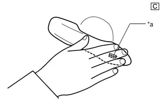
*a
Lock Sensor
The illustrations shown are examples only.
-
For details on the digital key diagnostic range, refer to Precautions for Outside Toyota Prius Vehicle Digital Key Detection Range/Diagnostic Range.
| Result | Proceed to |
|---|---|
| Entry function operates normally | A |
| Entry function does not operate normally | B |
| B |

| GO TO STEP 4 |
|

| 3. | CAUSE ANALYSIS |
(a) Using the GTS, check for Toyota Prius Vehicle Control History (RoB).
Body Electrical > Smart Key > Utility| Tester Display |
|---|
| Vehicle Control History (RoB) |
(b) Perform cause analysis.
Click here

(c) Take appropriate action in accordance with the result of the cause analysis.
| NEXT |

| END |
| 4. | CHECK BLE DOOR DIGITAL KEY RECEIVER ASSEMBLY (FOR FRONT PASSENGER DOOR) |
(a) Replace the BLE door digital key receiver assembly (for front passenger door) with a new one or used one.
Click here


(b) Use the digital key and check whether front passenger door lock/unlock is possible with the entry function.
Click here

| OK |

| END (BLE DOOR DIGITAL KEY RECEIVER ASSEMBLY (FOR FRONT PASSENGER DOOR) WAS DEFECTIVE) |
| NG |

| REPLACE DIGITAL KEY ECU ASSEMBLY
|


Back Door Entry Lock and Unlock Functions do not Operate
DESCRIPTION
Remove all causes of non-operation other than the vehicle components and vehicle settings. Under these conditions, if only back door lock and unlock using the digital key are not possible, there may be a malfunction in the communication system between the digital key ECU assembly and BLE luggage digital key receiver assembly, or a malfunction in the digital key ECU assembly and BLE luggage digital key receiver assembly.
CAUTION / NOTICE / HINT
NOTICE:
-
Before performing troubleshooting of the Toyota Prius vehicle, refer to Precautions for Inspection or Registration to check for a cause of the malfunction which is not related to vehicle settings or vehicle components.
Click here

- Perform troubleshooting with the electrical key transmitter sub-assembly not inside the detection area of the smart key system.
-
When using the digital key to perform door lock/unlock with the entry function, refer to Precautions for Outside Toyota Prius Vehicle Digital Key Detection Range/Diagnostic Range.
Click here

- Make sure that no DTCs are output. If any DTCs are output, proceed to Diagnostic Trouble Code Chart.
-
Cancel power saving mode before performing troubleshooting.
Click here

-
If the digital key system has been disabled, enable the system before performing troubleshooting.
Click here

-
Before replacing the digital key ECU assembly or BLE luggage digital key receiver assembly, refer to Registration.
Click here

PROCEDURE
| 1. | CHECK SMART KEY SYSTEM (for Entry Function) |
(a) Check the smart key system (for entry function).
Click here

OK:
Smart key system (for Entry Function) operates properly
| NG |

| GO TO SMART KEY SYSTEM (for Entry Function) (HOW TO PROCEED WITH TROUBLESHOOTING) |
|

| 2. | CHECK ENTRY FUNCTION (BACK DOOR) |
(a) Check whether it is possible to use the digital key to perform door lock/unlock with the entry function.
(1) Check the entry back door open function.
-
With the back door closed and locked, hold the digital key in your hand and hold your hand inside the digital key diagnostic range. Then operate the open switch.
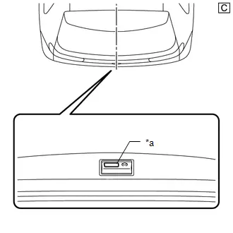
*a
Back Door Opener Switch Assembly (Open Switch)
The illustrations shown are examples only.
NOTICE:
-
With the back door closed and locked, hold the digital key in your hand and hold your hand inside the digital key diagnostic range. Then operate the open switch.
Click here

-
Refer to Precautions for Inspection or Registration regarding the digital key and surrounding environment.
Click here

-
With the back door closed and locked, hold the digital key in your hand and hold your hand inside the digital key diagnostic range. Then operate the open switch.
(2) Check the entry back door lock function.
-
With the back door closed and unlocked, hold the digital key in your hand and hold your hand inside the digital key diagnostic range. Then operate the lock switch.
NOTICE:
-
For details on the digital key diagnostic range, refer to Precautions for Outside Toyota Prius Vehicle Digital Key Detection Range/Diagnostic Range.
Click here

-
Refer to Precautions for Inspection or Registration regarding the digital key and surrounding environment.
Click here


*a
Back Door Opener Switch Assembly (Lock Switch)
The illustrations shown are examples only.
-
For details on the digital key diagnostic range, refer to Precautions for Outside Toyota Prius Vehicle Digital Key Detection Range/Diagnostic Range.
| Result | Proceed to |
|---|---|
| Entry function operates normally | A |
| Entry function does not operate normally | B |
| B |

| GO TO STEP 4 |
|

| 3. | CAUSE ANALYSIS |
(a) Using the GTS, check for Toyota Prius Vehicle Control History (RoB).
Body Electrical > Smart Key > Utility| Tester Display |
|---|
| Vehicle Control History (RoB) |
(b) Perform cause analysis.
Click here

(c) Take appropriate action in accordance with the result of the cause analysis.
| NEXT |

| END |
| 4. | CHECK BLE LUGGAGE DIGITAL KEY RECEIVER ASSEMBLY |
(a) Replace the BLE luggage digital key receiver assembly with a new one or used one.
Click here


(b) Use the digital key and check whether back door lock/unlock is possible with the entry function.
Click here

| OK |

| END (BLE LUGGAGE DIGITAL KEY RECEIVER ASSEMBLY WAS DEFECTIVE) |
| NG |

| REPLACE DIGITAL KEY ECU ASSEMBLY
|


Driver Side Door Entry Lock/Unlock Operation Range has Decreased
DESCRIPTION
Remove all causes of non-operation other than the vehicle components and vehicle settings. Under these conditions, if the digital key entry operation range is small, there may be a malfunction in the BLE door digital key receiver assembly (for driver door) and the digital key.
Also, if the smart entry function does not operate only when the digital key is at the height of the driver door glass, the Toyota Prius vehicle may be determining that the digital key is inside the vehicle.
CAUTION / NOTICE / HINT
NOTICE:
-
Before performing troubleshooting of the vehicle, refer to Precautions for Inspection or Registration to check for a cause of the malfunction which is not related to Toyota Prius vehicle settings or vehicle components.
Click here

- Perform troubleshooting with the electrical key transmitter sub-assembly not inside the detection area of the smart key system.
-
When using the digital key to perform door lock/unlock with the entry function, refer to Precautions for Digital Key Detection Range Outside.
Click here

- Make sure that no DTCs are output. If any DTCs are output, proceed to Diagnostic Trouble Code Chart.
-
Cancel power saving mode before performing troubleshooting.
Click here

-
If the digital key system has been disabled, enable the system before performing troubleshooting.
Click here

-
Before replacing the digital key ECU assembly or BLE door digital key receiver assembly (for driver door), refer to Registration.
Click here

PROCEDURE
| 1. | CHECK ENTRY FUNCTION (DRIVER DOOR) |
(a) While holding the digital key in the test range, perform a door lock/unlock using the entry function.*
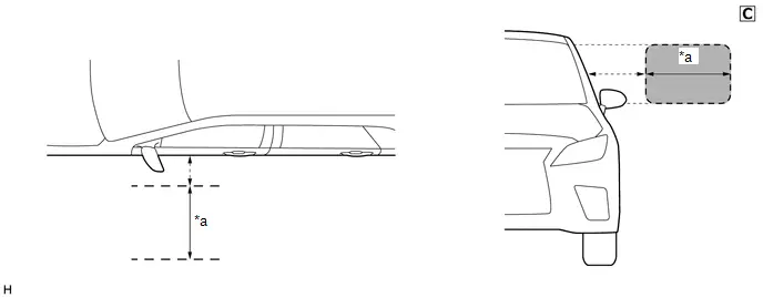
| *a | Test Range (approximately 50 - 100 cm (reference value measured using a typical device)) | - | - |
The illustrations shown are examples only.
NOTICE:
-
If the entry function does not operate when near the driver door glass, the Toyota Prius vehicle may be determining that the digital key is inside the vehicle.
Click here

-
Refer to Precautions for Inspection or Registration regarding the digital key and surrounding environment.
Click here

(b) Hold the key in your hand and hold your hand close to the digital key detection range. Then perform door lock/unlock using the entry function.*
NOTICE:
- For details on the digital key detection range, refer to Precautions for Outside Toyota Prius Vehicle Digital Key Detection Range/Diagnostic Range.
- Refer to Precautions for Inspection or Registration regarding the digital key and surrounding environment.
(c) Repeat * while moving your hand closer to and farther from the vehicle, and check the range where the entry function operates.
OK:
The entry function operates within the same range as usual
| Result | Proceed to |
|---|---|
| Operates within the digital key detection range | A |
| Digital key detection range is narrow | B |
| Operates within the digital key detection range, but does not operate within the test range | C |
| B |

| GO TO STEP 3 |
| C |

| GO TO STEP 11 |
|

| 2. | CAUSE ANALYSIS |
(a) Using the GTS, check for Toyota Prius Vehicle Control History (RoB).
Body Electrical > Smart Key > Utility| Tester Display |
|---|
| Vehicle Control History (RoB) |
(b) Perform cause analysis.
Click here

(c) Take appropriate action in accordance with the result of the cause analysis.
| NEXT |

| END |
| 3. | CHECK DIGITAL KEY DIAGNOSTIC MODE (DRIVER DOOR) |
NOTICE:
With only one digital key connected to BLE, perform inspection in digital key diagnostic mode.
(a) Check the BLE door digital key receiver assembly (for driver door) in digital key diagnostic mode.
(1) Using the GTS, select Body Electrical / Smart Key / Utility / Communication Check (Digital Key Diag Mode) / Digital key driver door outside area
Body Electrical > Smart Key > Utility| Tester Display |
|---|
| Communication Check (Digital Key Diag Mode) |
(2) Hold the digital key in your hand, and hold your hand close to the digital key detection range. Check that the wireless buzzer sounds.*
NOTICE:
- For details on the digital key detection range, refer to Precautions for Outside Toyota Prius Vehicle Digital Key Detection Range/Diagnostic Range.
- Refer to Precautions for Inspection or Registration regarding the digital key and surrounding environment.
(3) Repeat * while moving your hand closer to and farther from the vehicle, and check the range where the wireless buzzer sounds.
| Result | Proceed to |
|---|---|
| The wireless buzzer sounds within a narrower range than the usual operating range | A |
| The wireless buzzer does not sound | B |
| B |

| GO TO OTHER PROBLEM (Driver Side Door Entry Lock and Unlock Functions do not Operate) |
|

| 4. | CHECK ANOTHER DIGITAL KEY |
(a) Check if there is digital key available that is already registered to the Toyota Prius vehicle.
| Result | Proceed to |
|---|---|
| Another registered digital key is not available | A |
| Another registered digital key is available | B |
| B |

| GO TO STEP 7 |
|

| 5. | CHECK USING ANOTHER Toyota Prius Vehicle |
(a) Check if another vehicle equipped with digital key system is available
| Result | Proceed to |
|---|---|
| Toyota Prius Vehicle equipped with digital key system not available | A |
| Vehicle equipped with digital key system available | B |
| B |

| GO TO STEP 9 |
|

| 6. | REGISTER NEW SHARE KEY |
(a) Register a share key.
HINT:
Refer to the digital key application.
|

| 7. | CHECK ENTRY FUNCTION (DRIVER DOOR) |
(a) Hold a different registered digital key in your hand hold your hand close to the digital key detection range. Then perform door lock/unlock using the entry function.*
NOTICE:
- For details on the digital key detection range, refer to Precautions for Outside Toyota Prius Vehicle Digital Key Detection Range/Diagnostic Range.
- Refer to Precautions for Inspection or Registration regarding the digital key and surrounding environment.
(b) Repeat * while moving your hand closer to and farther from the vehicle, and check the range where the entry function operates.
OK:
The entry function operates within the same range as usual
| OK |

| END (PERFORM TROUBLESHOOTING ON ORIGINAL DIGITAL KEY) |
|

| 8. | CHECK THE INSTALLATION CONDITION OF BLE DOOR DIGITAL KEY RECEIVER ASSEMBLY (FOR DRIVER DOOR) |
(a) Install BLE door digital key receiver assembly (for driver door) properly.
Click here


| OK |

| REPLACE BLE DOOR DIGITAL KEY RECEIVER ASSEMBLY (FOR DRIVER DOOR)
|


| NG |

| END (INSTALL THE BLE DOOR DIGITAL KEY RECEIVER ASSEMBLY (FOR DRIVER DOOR) TO THE STANDARD LOCATION) |
| 9. | REGISTER NEW SHARE KEY |
(a) Register a share key that did not operate correctly within the default operating range to another Toyota Prius vehicle equipped with a digital key system.
HINT:
Refer to the digital key application.
|

| 10. | CHECK ENTRY FUNCTION (DRIVER DOOR) |
(a) Hold a registered digital key in your hand and hold your hand close to the digital key detection range. Then perform door lock/unlock using the entry function.*
NOTICE:
- For details on the digital key detection range, refer to Precautions for Outside Toyota Prius Vehicle Digital Key Detection Range/Diagnostic Range.
- Refer to Precautions for Inspection or Registration regarding the digital key and surrounding environment.
(b) Repeat * while moving your hand closer to and farther from the vehicle, and check the range where the entry function operates.
OK:
The entry function operates within the same range as usual
| OK |

| GO TO STEP 8 |
| NG |

| END (PERFORM TROUBLESHOOTING ON ORIGINAL DIGITAL KEY) |
| 11. | DIGITAL KEY DIAGNOSTIC MODE (FRONT FLOOR) |
NOTICE:
With only one digital key connected to BLE, perform inspection in digital key diagnostic mode.
(a) Check the BLE indoor digital key receiver assembly in digital key diagnostic mode.
(1) Using the GTS, select Body Electrical / Smart Key / Utility / Communication Check (Digital Key Diag Mode) / Digital key engine/power start area
Body Electrical > Smart Key > Utility| Tester Display |
|---|
| Communication Check (Digital Key Diag Mode) |
(2) While holding the digital key in the test range, check that the wireless buzzer sounds.

| *a | Test Range (approximately 50 - 100 cm (reference value measured using a typical device)) | - | - |
The illustrations shown are examples only.
| Result | Proceed to |
|---|---|
| The wireless buzzer does not sound | A |
| The wireless buzzer sounds | B |
| A |

| END (NO MALFUNCTION) HINT: The range of the digital key detection area differs greatly depending on the type of digital key device, the way the device is held and the surrounding environment, etc. Explain to the customer that entry function did not operate while they were outside the range of the digital key detection area. |
|

| 12. | CHECK THE INSTALLATION CONDITION OF BLE INDOOR DIGITAL KEY RECEIVER ASSEMBLY |
| (a) Check that the wire harness is not contacting or hanging near the BLE indoor digital key receiver assembly. Click here
NOTICE: If the wire harness is contacting or hanging near the BLE indoor digital key receiver assembly, the Toyota Prius vehicle interior digital key detection range will change. |
|


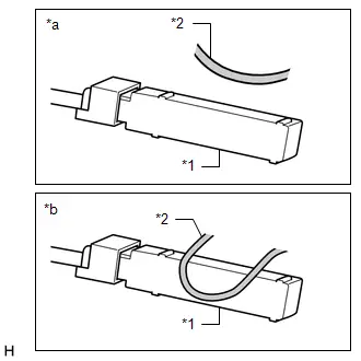
| OK |

| REPLACE BLE INDOOR DIGITAL KEY RECEIVER ASSEMBLY
|


| NG |

| END (ADJUST WIRE HARNESS POSITION) |
Front Passenger Side Door Entry Lock/Unlock Operation Range has Decreased
DESCRIPTION
Remove all causes of non-operation other than the vehicle components and vehicle settings. Under these conditions, if the digital key entry operation range is small, there may be a malfunction in the BLE door digital key receiver assembly (for front passenger door) and the digital key.
Also, if the smart entry function does not operate only when the digital key is at the height of the passenger door glass, the Toyota Prius vehicle may be determining that the digital key is inside the vehicle.
CAUTION / NOTICE / HINT
NOTICE:
-
Before performing troubleshooting of the vehicle, refer to Precautions for Inspection or Registration to check for a cause of the malfunction which is not related to Toyota Prius vehicle settings or vehicle components.
Click here

- Perform troubleshooting with the electrical key transmitter sub-assembly not inside the detection area of the smart key system.
-
When using the digital key to perform door lock/unlock with the entry function, refer to Precautions for Outside Toyota Prius Vehicle Digital Key Detection Range/Diagnostic Range.
Click here

- Make sure that no DTCs are output. If any DTCs are output, proceed to Diagnostic Trouble Code Chart.
-
Cancel power saving mode before performing troubleshooting.
Click here

-
If the digital key system has been disabled, enable the system before performing troubleshooting.
Click here

-
Before replacing the BLE door digital key receiver assembly (for front passenger door), refer to Registration.
Click here

PROCEDURE
| 1. | CHECK ENTRY FUNCTION (FRONT PASSENGER DOOR) |
(a) While holding the digital key in the test range, perform a door lock/unlock using the entry function.*

| *a | Test Range (approximately 50 - 100 cm (reference value measured using a typical device)) | - | - |
The illustrations shown are examples only.
NOTICE:
- If the entry function does not operate when near the passenger door glass, the Toyota Prius vehicle may be determining that the digital key is inside the vehicle.
- Refer to Precautions for Inspection or Registration regarding the digital key and surrounding environment.
(b) Hold the key in your hand and hold your hand close to the digital key detection range. Then perform door lock/unlock using the entry function.*
NOTICE:
-
For details on the digital key detection range, refer to Precautions for Outside Toyota Prius Vehicle Digital Key Detection Range/Diagnostic Range.
Click here

-
Refer to Precautions for Inspection or Registration regarding the digital key and surrounding environment.
Click here

(c) Repeat * while moving your hand closer to and farther from the Toyota Prius vehicle, and check the range where the entry function operates.
OK:
The entry function operates within the same range as usual
| Result | Proceed to |
|---|---|
| Operates within the digital key detection range | A |
| Digital key detection range is narrow | B |
| Operates within the digital key detection range, but does not operate within the test range | C |
| B |

| GO TO STEP 3 |
| C |

| GO TO STEP 11 |
|

| 2. | CAUSE ANALYSIS |
(a) Using the GTS, check for Toyota Prius Vehicle Control History (RoB).
Body Electrical > Smart Key > Utility| Tester Display |
|---|
| Vehicle Control History (RoB) |
(b) Perform cause analysis.
Click here

(c) Take appropriate action in accordance with the result of the cause analysis.
| NEXT |

| END |
| 3. | CHECK DIGITAL KEY DIAGNOSTIC MODE (FRONT PASSENGER DOOR) |
NOTICE:
With only one digital key connected to BLE, perform inspection in digital key diagnostic mode.
(a) Check the BLE door digital key receiver assembly (for front passenger door) in digital key diagnostic mode.
(1) Using the GTS, select Body Electrical / Smart Key / Utility / Communication Check (Digital Key Diag Mode) / Digital key passenger door outside area
Body Electrical > Smart Key > Utility| Tester Display |
|---|
| Communication Check (Digital Key Diag Mode) |
(2) Hold the digital key in your hand, and hold your hand close to the digital key detection range. Check that the wireless buzzer sounds.*
NOTICE:
- For details on the digital key detection range, refer to Precautions for Outside Toyota Prius Vehicle Digital Key Detection Range/Diagnostic Range.
- Refer to Precautions for Inspection or Registration regarding the digital key and surrounding environment.
(3) Repeat * while moving your hand closer to and farther from the vehicle, and check the range where the wireless buzzer sounds.
| Result | Proceed to |
|---|---|
| The wireless buzzer sounds within a narrower range than the usual operating range | A |
| The wireless buzzer does not sound | B |
| B |

| GO TO OTHER PROBLEM (FRONT PASSENGER SIDE DOOR ENTRY LOCK AND UNLOCK FUNCTIONS DO NOT OPERATE) |
|

| 4. | CHECK ANOTHER DIGITAL KEY |
(a) Check if there is digital key available that is already registered to the Toyota Prius vehicle.
| Result | Proceed to |
|---|---|
| Another registered digital key is not available | A |
| Another registered digital key is available | B |
| B |

| GO TO STEP 7 |
|

| 5. | CHECK USING ANOTHER Toyota Prius Vehicle |
(a) Check if another vehicle equipped with digital key system is available
| Result | Proceed to |
|---|---|
| Toyota Prius Vehicle equipped with digital key system not available | A |
| Vehicle equipped with digital key system available | B |
| B |

| GO TO STEP 9 |
|

| 6. | REGISTER NEW SHARE KEY |
(a) Register a share key.
HINT:
Refer to the digital key application.
|

| 7. | CHECK ENTRY FUNCTION (FRONT PASSENGER DOOR) |
(a) Hold a different registered digital key in your hand hold your hand close to the digital key detection range. Then perform door lock/unlock using the entry function.*
NOTICE:
- For details on the digital key detection range, refer to Precautions for Outside Toyota Prius Vehicle Digital Key Detection Range/Diagnostic Range.
- Refer to Precautions for Inspection or Registration regarding the digital key and surrounding environment.
(b) Repeat * while moving your hand closer to and farther from the vehicle, and check the range where the entry function operates.
OK:
The entry function operates within the same range as usual
| OK |

| END (PERFORM TROUBLESHOOTING ON ORIGINAL DIGITAL KEY) |
|

| 8. | CHECK THE INSTALLATION CONDITION OF BLE DOOR DIGITAL KEY RECEIVER ASSEMBLY (FOR FRONT PASSENGER DOOR) |
(a) Install BLE door digital key receiver assembly (for front passenger door) properly.
Click here


| OK |

| REPLACE BLE DOOR DIGITAL KEY RECEIVER ASSEMBLY (FOR FRONT PASSENGER DOOR)
|


| NG |

| END (INSTALL THE BLE DOOR DIGITAL KEY RECEIVER ASSEMBLY (FOR FRONT PASSENGER DOOR) TO THE STANDARD LOCATION) |
| 9. | REGISTER NEW SHARE KEY |
(a) Register a share key that did not operate correctly within the default operating range to another Toyota Prius vehicle equipped with a digital key system.
HINT:
Refer to the digital key application.
|

| 10. | CHECK ENTRY FUNCTION (FRONT PASSENGER DOOR) |
(a) Hold a registered digital key in your hand and hold your hand close to the digital key detection range. Then perform door lock/unlock using the entry function.*
NOTICE:
- For details on the digital key detection range, refer to Precautions for Outside Toyota Prius Vehicle Digital Key Detection Range/Diagnostic Range.
- Refer to Precautions for Inspection or Registration regarding the digital key and surrounding environment.
(b) Repeat * while moving your hand closer to and farther from the vehicle, and check the range where the entry function operates.
OK:
The entry function operates within the same range as usual
| OK |

| GO TO STEP 8 |
| NG |

| END (PERFORM TROUBLESHOOTING ON ORIGINAL DIGITAL KEY) |
| 11. | DIGITAL KEY DIAGNOSTIC MODE (FRONT FLOOR) |
NOTICE:
With only one digital key connected to BLE, perform inspection in digital key diagnostic mode.
(a) Check the BLE indoor digital key receiver assembly in digital key diagnostic mode.
(1) Using the GTS, select Body Electrical / Smart Key / Utility / Communication Check (Digital Key Diag Mode) / Digital key engine/power start area
Body Electrical > Smart Key > Utility| Tester Display |
|---|
| Communication Check (Digital Key Diag Mode) |
(2) While holding the digital key in the test range, check that the wireless buzzer sounds.
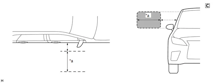
| *a | Test Range (approximately 50 - 100 cm (reference value measured using a typical device)) | - | - |
The illustrations shown are examples only.
| Result | Proceed to |
|---|---|
| The wireless buzzer does not sound | A |
| The wireless buzzer sounds | B |
| A |

| END (NO MALFUNCTION) HINT: The range of the digital key detection area differs greatly depending on the type of digital key device, the way the device is held and the surrounding environment, etc. Explain to the customer that the entry function did not operate while they were outside the range of the digital key detection area. |
|

| 12. | CHECK THE INSTALLATION CONDITION OF BLE INDOOR DIGITAL KEY RECEIVER ASSEMBLY |
| (a) Check that the wire harness is not contacting or hanging near the BLE indoor digital key receiver assembly. Click here
NOTICE: If the wire harness is contacting or hanging near the BLE indoor digital key receiver assembly, the Toyota Prius vehicle interior digital key detection range will change. |
|


| OK |

| REPLACE BLE INDOOR DIGITAL KEY RECEIVER ASSEMBLY
|


| NG |

| END (ADJUST WIRE HARNESS POSITION) |
Back Door Entry Lock/Unlock Operation Range has Decreased
DESCRIPTION
Remove all causes of non-operation other than the vehicle components and vehicle settings. Under these conditions, if the digital key entry operation range is small, there may be a malfunction in the BLE luggage digital key receiver assembly and the digital key.
CAUTION / NOTICE / HINT
NOTICE:
-
Before performing troubleshooting of the Toyota Prius vehicle, refer to Precautions for Inspection or Registration to check for a cause of the malfunction which is not related to vehicle settings or vehicle components.
Click here

- Perform troubleshooting with the electrical key transmitter sub-assembly not inside the detection area of the smart key system.
-
When using the digital key to perform door lock/unlock with the entry function, refer to Precautions for Outside Toyota Prius Vehicle Digital Key Detection Range/Diagnostic Range.
Click here

- Make sure that no DTCs are output. If any DTCs are output, proceed to Diagnostic Trouble Code Chart.
-
Cancel power saving mode before performing troubleshooting.
Click here

-
If the digital key system has been disabled, enable the system before performing troubleshooting.
Click here

-
Before replacing the BLE luggage digital key receiver assembly, refer to Registration.
Click here

PROCEDURE
| 1. | CHECK ENTRY FUNCTION (BACK DOOR) |
(a) Hold the key in your hand and hold your hand close to the digital key detection range. Then perform door lock/unlock using the entry function.*
NOTICE:
-
For details on the digital key detection range, refer to Precautions for Outside Toyota Prius Vehicle Digital Key Detection Range/Diagnostic Range.
Click here

-
Refer to Precautions for Inspection or Registration regarding the digital key and surrounding environment.
Click here

(b) Repeat * while moving your hand closer to and farther from the Toyota Prius vehicle, and check the range where the entry function operates.
OK:
The entry function operates within the same range as usual
| NG |

| GO TO STEP 3 |
|

| 2. | CAUSE ANALYSIS |
(a) Using the GTS, check for Toyota Prius Vehicle Control History (RoB).
Body Electrical > Smart Key > Utility| Tester Display |
|---|
| Vehicle Control History (RoB) |
(b) Perform cause analysis.
Click here

(c) Take appropriate action in accordance with the result of the cause analysis.
| NEXT |

| END |
| 3. | CHECK DIGITAL KEY DIAGNOSTIC MODE (BACK DOOR) |
NOTICE:
With only one digital key connected to BLE, perform inspection in digital key diagnostic mode.
(a) Check the BLE luggage digital key receiver assembly in digital key diagnostic mode.
(1) Using the GTS, select Body Electrical / Smart Key / Utility / Communication Check (Digital Key Diag Mode) / Digital key back door/trunk lid outside area
Body Electrical > Smart Key > Utility| Tester Display |
|---|
| Communication Check (Digital Key Diag Mode) |
(2) Hold the digital key in your hand, and hold your hand close to the digital key detection range. Check that the wireless buzzer sounds.*
NOTICE:
- For details on the digital key detection range, refer to Precautions for Outside Toyota Prius Vehicle Digital Key Detection Range/Diagnostic Range.
- Refer to Precautions for Inspection or Registration regarding the digital key and surrounding environment.
(3) Repeat * while moving your hand closer to and farther from the vehicle, and check the range where the wireless buzzer sounds.
| Result | Proceed to |
|---|---|
| The wireless buzzer sounds within a narrower range than the usual operating range | A |
| The wireless buzzer does not sound | B |
| B |

| GO TO OTHER PROBLEM |
|

| 4. | CHECK ANOTHER DIGITAL KEY |
(a) Check if there is digital key available that is already registered to the Toyota Prius vehicle.
| Result | Proceed to |
|---|---|
| Another registered digital key is not available | A |
| Another registered digital key is available | B |
| B |

| GO TO STEP 7 |
|

| 5. | CHECK USING ANOTHER Toyota Prius Vehicle |
(a) Check if another vehicle equipped with digital key system is available
| Result | Proceed to |
|---|---|
| Toyota Prius Vehicle equipped with digital key system not available | A |
| Vehicle equipped with digital key system available | B |
| B |

| GO TO STEP 9 |
|

| 6. | REGISTER NEW SHARE KEY |
(a) Register a share key.
HINT:
Refer to the digital key application.
|

| 7. | CHECK ENTRY FUNCTION (BACK DOOR) |
(a) a. Hold a different registered digital key in your hand hold your hand close to the digital key detection range. Then perform door lock/unlock using the entry function.*
NOTICE:
- For details on the digital key detection range, refer to Precautions for Outside Toyota Prius Vehicle Digital Key Detection Range/Diagnostic Range.
- Refer to Precautions for Inspection or Registration regarding the digital key and surrounding environment.
(b) Repeat * while moving your hand closer to and farther from the vehicle, and check the range where the entry function operates.
OK:
The entry function operates within the same range as usual
| OK |

| END (PERFORM TROUBLESHOOTING ON ORIGINAL DIGITAL KEY) |
|

| 8. | CHECK THE INSTALLATION CONDITION OF BLE LUGGAGE DIGITAL KEY RECEIVER ASSEMBLY |
(a) Install BLE luggage digital key receiver assembly properly.
Click here


| OK |

| REPLACE BLE LUGGAGE DIGITAL KEY RECEIVER ASSEMBLY
|


| NG |

| END (INSTALL THE BLE LUGGAGE DIGITAL KEY RECEIVER ASSEMBLY TO THE STANDARD LOCATION) |
| 9. | REGISTER NEW SHARE KEY |
(a) Register a share key that did not operate correctly within the default operating range to another Toyota Prius vehicle equipped with a digital key system.
HINT:
Refer to the digital key application.
|

| 10. | CHECK ENTRY FUNCTION (BACK DOOR) |
(a) Hold a registered digital key in your hand and hold your hand close to the digital key detection range. Then perform door lock/unlock using the entry function.*
NOTICE:
- For details on the digital key detection range, refer to Precautions for Outside Toyota Prius Vehicle Digital Key Detection Range/Diagnostic Range.
- Refer to Precautions for Inspection or Registration regarding the digital key and surrounding environment.
(b) Repeat * while moving your hand closer to and farther from the vehicle, and check the range where the entry function operates.
OK:
The entry function operates within the same range as usual
| OK |

| GO TO STEP 8 |
| NG |

| END (PERFORM TROUBLESHOOTING ON ORIGINAL DIGITAL KEY) |
Power Source Mode does not Change (No Interior Verification)
DESCRIPTION
When the power source mode does not change even after removing the cause of the malfunction which is not related to vehicle settings and vehicle components, in-vehicle verification has not been performed. There may be a malfunction in the communication system between the certification ECU (smart key ECU assembly) and digital key ECU assembly or digital key.
CAUTION / NOTICE / HINT
NOTICE:
-
Before performing troubleshooting of the Toyota Prius vehicle, refer to Precautions for Inspection or Registration to check for a cause of the malfunction which is not related to vehicle settings or vehicle components.
Click here

- Perform troubleshooting with the electrical key transmitter sub-assembly not inside the detection area of the smart key system.
-
When changing the power source mode, refer to precautions regarding the in-Toyota Prius vehicle operating range and make sure the digital key is within the in-vehicle operating range
Click here

- Make sure that no DTCs are output. If any DTCs are output, proceed to Diagnostic Trouble Code Chart.
-
If the digital key system has been disabled, enable the system before performing troubleshooting.
Click here

-
Before replacing the certification ECU (smart key ECU assembly), digital key ECU assembly or BLE indoor digital key receiver assembly, refer to Registration.
Click here

PROCEDURE
| 1. | CHECK SMART KEY SYSTEM (for Start Function) |
(a) Check the smart key system (for Start Function).
Click here

OK:
Smart key system (Start Function) operates normally
| NG |

| GO TO SMART KEY SYSTEM (for Start Function) (HOW TO PROCEED WITH TROUBLESHOOTING) |
|

| 2. | CHECK POWER SOURCE MODE CHANGING FUNCTION |
(a) Place the digital key on the center console near the Toyota Prius vehicle interior BLE digital key receiver.
NOTICE:
- Make sure there is no electronic device that outputs high-voltage or noise inside or around the vehicle.
- Make sure that the digital key is not covered by or touching a metal object.
(b) Check the power source mode changing function.
OK:
Power source mode can be changed
| NG |

| GO TO STEP 4 |
|

| 3. | CAUSE ANALYSIS |
(a) Using the GTS, check for Toyota Prius Vehicle Control History (RoB).
Body Electrical > Smart Key > Utility| Tester Display |
|---|
| Vehicle Control History (RoB) |
(b) Perform cause analysis.
Click here

(c) Take appropriate action in accordance with the result of the cause analysis.
| NEXT |

| END (PERFORM TROUBLESHOOTING ON ORIGINAL DIGITAL KEY) |
| 4. | CHECK DIGITAL KEY DISPLAY |
(a) Check the message display of the digital key.
NOTICE:
If a message is not displayed on the digital key, a BLE connection cannot be established.
| Result | Proceed to |
|---|---|
| Message indicating out of operating range or digital key system malfunction is displayed | A |
| Other than above is displayed | B |
| BLE connection cannot be established | C |
| B |

| END (PERFORM DIGITAL KEY TROUBLESHOOTING) |
| C |

| GO TO OTHER PROBLEM (Cannot Connect to BLE) |
|

| 5. | CHECK ANOTHER DIGITAL KEY |
(a) Check if there is digital key available that is already registered to the Toyota Prius vehicle.
| Result | Proceed to |
|---|---|
| Another registered digital key is not available | A |
| Another registered digital key is available | B |
| B |

| GO TO STEP 8 |
|

| 6. | CHECK USING ANOTHER Toyota Prius Vehicle |
(a) Check if another vehicle equipped with digital key system is available
| Result | Proceed to |
|---|---|
| Toyota Prius Vehicle equipped with digital key system not available | A |
| Vehicle equipped with digital key system available | B |
| B |

| GO TO STEP 14 |
|

| 7. | REGISTER NEW SHARE KEY |
(a) Register a share key.
HINT:
Refer to the digital key application.
|

| 8. | CHECK POWER SOURCE MODE CHANGING FUNCTION |
(a) Place another registered digital key on the center console near the Toyota Prius vehicle interior BLE digital key receiver.
NOTICE:
- Make sure there is no electronic device that outputs high-voltage or noise inside or around the vehicle.
- Make sure that the digital key is not covered by or touching a metal object.
(b) Check the power source mode changing function.
OK:
Power source mode can be changed
| OK |

| END (PERFORM TROUBLESHOOTING ON ORIGINAL DIGITAL KEY) |
|

| 9. | CHECK BLE INDOOR DIGITAL KEY RECEIVER ASSEMBLY |
(a) Replace the BLE indoor digital key receiver assembly with a new one or used one.
Click here


(b) Place the digital key on the center console near the Toyota Prius vehicle interior BLE digital key receiver.
NOTICE:
- Make sure there is no electronic device that outputs high-voltage or noise inside or around the vehicle.
- Make sure that the digital key is not covered by or touching a metal object.
(c) Check the power source mode changing function.
| OK |

| END (BLE INDOOR DIGITAL KEY RECEIVER ASSEMBLY WAS DEFECTIVE) |
|

| 10. | REPLACE DIGITAL KEY ECU ASSEMBLY |
(a) Replace the digital key ECU assembly with a new one.
Click here


|

| 11. | REGISTER DIGITAL KEY CODE |
(a) Register the digital key code to the digital key ECU assembly.
Click here

|

| 12. | REGISTER NEW OWNER KEY |
(a) Register the owner key using the original digital key.
HINT:
Refer to the digital key application.
|

| 13. | CHECK POWER SOURCE MODE CHANGING FUNCTION |
(a) Place another registered digital key on the center console near the Toyota Prius vehicle interior BLE digital key receiver.
NOTICE:
- Make sure there is no electronic device that outputs high-voltage or noise inside or around the vehicle.
- Make sure that the digital key is not covered by or touching a metal object.
(b) Check the power source mode changing function.
OK:
Power source mode can be changed
| OK |

| END (DIGITAL KEY ECU ASSEMBLY WAS DEFECTIVE) |
| NG |

| REPLACE CERTIFICATION ECU (SMART KEY ECU ASSEMBLY)
|


| 14. | REGISTER NEW SHARE KEY |
(a) Register the share key with which the power source mode could not be changed to another Toyota Prius vehicle equipped with a digital key system.
HINT:
Refer to the digital key application.
|

| 15. | CHECK POWER SOURCE MODE CHANGING FUNCTION |
(a) Place the digital key on the center console near the Toyota Prius vehicle interior BLE digital key receiver of another vehicle equipped with the digital key system.
NOTICE:
- Make sure there is no electronic device that outputs high-voltage or noise inside or around the vehicle.
- Make sure that the digital key is not covered by or touching a metal object.
(b) Check the power source mode changing function.
OK:
Power source mode can be changed
| OK |

| GO TO STEP 9 |
| NG |

| END (PERFORM TROUBLESHOOTING ON ORIGINAL DIGITAL KEY) |
The Operation Range of the Power Source Switching Function has Decreased
DESCRIPTION
When the power source mode does not change even after removing the cause of the malfunction which is not related to vehicle settings and vehicle components, the BLE indoor digital key receiver assembly or digital key may be malfunctioning.
CAUTION / NOTICE / HINT
NOTICE:
-
Before performing troubleshooting of the Toyota Prius vehicle, refer to Precautions for Inspection or Registration to check for a cause of the malfunction which is not related to vehicle settings or vehicle components.
Click here

- Perform troubleshooting with the electrical key transmitter sub-assembly not inside the detection area of the smart key system.
-
If the power source does not change, refer to precautions regarding the in-Toyota Prius vehicle operating range and make sure the digital key is within the in-vehicle operating range.
Click here

- Make sure that no DTCs are output. If any DTCs are output, proceed to Diagnostic Trouble Code Chart.
-
If the digital key system has been disabled, enable the system before performing troubleshooting.
Click here

-
Before replacing the BLE indoor digital key receiver assembly, refer to Service Registration.
Click here

PROCEDURE
| 1. | CHECK POWER SOURCE MODE CHANGING FUNCTION |
(a) Hold the digital key above the center console near the Toyota Prius vehicle interior BLE digital key receiver and operate the power switch.
NOTICE:
- Make sure there is no electronic device that outputs high-voltage or noise inside or around the vehicle.
- Make sure that the digital key is not covered by or touching a metal object.
(b) While moving the digital device closer to and farther away from the center console while repeatedly changing the power source mode, check the operating range.
OK:
The range at which the power source mode can be changed is the same as the default.
| NG |

| GO TO STEP 3 |
|

| 2. | CAUSE ANALYSIS |
(a) Using the GTS, check for Toyota Prius Vehicle Control History (RoB).
Body Electrical > Smart Key > Utility| Tester Display |
|---|
| Vehicle Control History (RoB) |
(b) Perform cause analysis.
Click here

(c) Take appropriate action in accordance with the result of the cause analysis.
| NEXT |

| END |
| 3. | CHECK DIGITAL KEY DIAGNOSTIC MODE (FRONT FLOOR) |
NOTICE:
With only one digital key connected to BLE, perform inspection in digital key diagnostic mode.
(a) Check the BLE indoor digital key receiver assembly in key diagnostic mode.
(1) Using the GTS, select Body Electrical / Smart Key / Utility / Communication Check (Digital Key Diag Mode) / Digital key engine/power start area
Body Electrical > Smart Key > Utility| Tester Display |
|---|
| Communication Check (Digital Key Diag Mode) |
(2) While holding the digital key in the in-Toyota Prius vehicle operating range, check that the wireless buzzer sounds
NOTICE:
- Make sure there is no electronic device that outputs high-voltage or noise inside or around the vehicle.
- Make sure that the digital key is not covered by or touching a metal object.
(3) While moving the digital device closer to and farther away from the center console, check the wireless buzzer sound range.
| Result | Proceed to |
|---|---|
| The wireless buzzer sounds when in an operating range smaller than the default of the power source mode changing function | A |
| Wireless buzzer does not sound | B |
| B |

| GO TO OTHER PROBLEM |
|

| 4. | CHECK ANOTHER DIGITAL KEY |
(a) Check if there is digital key available that is already registered to the Toyota Prius vehicle.
| Result | Proceed to |
|---|---|
| Another registered digital key is not available | A |
| Another registered digital key is available | B |
| B |

| GO TO STEP 7 |
|

| 5. | CHECK USING ANOTHER Toyota Prius Vehicle |
(a) Check if another vehicle equipped with digital key system is available
| Result | Proceed to |
|---|---|
| Toyota Prius Vehicle equipped with digital key system not available | A |
| Vehicle equipped with digital key system available | B |
| B |

| GO TO STEP 9 |
|

| 6. | REGISTER NEW SHARE KEY |
(a) Register a share key.
HINT:
Refer to the digital key application.
|

| 7. | CHECK POWER SOURCE MODE CHANGING FUNCTION |
(a) Hold a registered digital key above the center console near the Toyota Prius vehicle interior BLE digital key receiver and operate the power switch.
NOTICE:
- Make sure there is no electronic device that outputs high-voltage or noise inside or around the vehicle.
- Make sure that the digital key is not covered by or touching a metal object.
(b) While moving the digital device closer to and farther away from the center console while repeatedly changing the power source mode, check the operating range.
OK:
The range at which the power source mode can be changed is the same as the default.
| OK |

| END (PERFORM TROUBLESHOOTING ON ORIGINAL DIGITAL KEY) |
|

| 8. | CHECK THE INSTALLATION CONDITION OF BLE INDOOR DIGITAL KEY RECEIVER ASSEMBLY |
| (a) Check that the wire harness is not contacting or hanging near the BLE indoor digital key receiver assembly. Click here
NOTICE: If the wire harness is contacting or hanging near the BLE indoor digital key receiver assembly, the Toyota Prius vehicle interior digital key detection range will change. |
|


(b) Install BLE indoor digital key receiver assembly properly.
Click here


| Result | Proceed to |
|---|---|
| OK | A |
| NG (Wire harness is contacting or hanging) | B |
| NG (Not installed correctly) | C |
| A |

| REPLACE BLE INDOOR DIGITAL KEY RECEIVER ASSEMBLY
|


| B |

| END (ADJUST WIRE HARNESS POSITION) |
| C |

| END (INSTALL THE BLE INDOOR DIGITAL KEY RECEIVER ASSEMBLY TO THE STANDARD LOCATION) |
| 9. | REGISTER NEW SHARE KEY |
(a) Register a share key that did not operate correctly within the default operating range to another Toyota Prius vehicle equipped with a digital key system.
HINT:
Refer to the digital key application.
|

| 10. | CHECK POWER SOURCE MODE CHANGING FUNCTION |
(a) Hold a registered digital key above the center console near the Toyota Prius vehicle interior BLE digital key receiver and operate the power switch.
NOTICE:
- Make sure there is no electronic device that outputs high-voltage or noise inside or around the vehicle.
- Make sure that the digital key is not covered by or touching a metal object.
(b) While moving the digital device closer to and farther away from the center console while repeatedly changing the power source mode, check the operating range.
OK:
The range at which the power source mode can be changed is the same as the default.
| OK |

| GO TO STEP 8 |
| NG |

| END (PERFORM TROUBLESHOOTING ON ORIGINAL DIGITAL KEY) |
New Key cannot be Registered (Owner Key)
DESCRIPTION
-
When performing new registration of a digital key using the digital key application, the mobile device first communicates with the service center. Then, the vehicle communicates with the service center via the telematics system, then the digital key pairs with the Toyota Prius vehicle via BLE.
If a registration malfunction occurs before the digital key has paired with the vehicle, it should be suspected that the cause is by misoperation of components outside of the vehicle, a telematics system malfunction, or a digital key ECU assembly malfunction.
If a registration malfunction occurs after the digital key has paired with the Toyota Prius vehicle, it should be suspected that the cause is the communication system between the digital key ECU assembly and certification ECU (smart key ECU assembly), certification ECU (smart key ECU assembly) or digital key ECU assembly.
-
If a new share key cannot be registered, refer to Additional Key cannot be Registered (Share Key).
Click here

CAUTION / NOTICE / HINT
NOTICE:
-
Before performing troubleshooting of the Toyota Prius vehicle, refer to Precautions for Inspection or Registration to check for a cause of the malfunction which is not related to vehicle settings or vehicle components.
Click here

- Make sure that no DTCs are output. If any DTCs are output, proceed to Diagnostic Trouble Code Chart.
-
If the digital key system has been disabled, enable the system before performing troubleshooting.
Click here

-
Before replacing the certification ECU (smart key ECU assembly) or digital key ECU assembly, refer to Registration.
Click here

PROCEDURE
| 1. | READ VALUE USING GTS (OWNER'S DIGITAL KEY REGISTRATION STATUS) |
(a) Read the Data List according to the display on the GTS.
Body Electrical > Smart Key > Data List| Tester Display | Measurement Item | Range | Normal Condition | Diagnostic Note |
|---|---|---|---|---|
| Owner's Digital Key Registration Status | Registration status of owner key | Not Registered or Registered | Not Registered: Not registered Registered: Registered | - |
| Tester Display |
|---|
| Owner's Digital Key Registration Status |
| Result | Proceed to |
|---|---|
| Owner key is registered | A |
| Owner key is not registered | B |
| B |

| GO TO STEP 3 |
|

| 2. | CLEAR ALL REGISTERED DIGITAL KEYS |
(a) Clear all registered digital keys.
Click here

OK:
All digital keys can be cleared
| NEXT |

| END (PERFORM OWNER KEY REGISTRATION) |
| 3. | REGISTER NEW OWNER KEY |
(a) Using the digital key application, perform new registration of the owner key from inside the Toyota Prius vehicle.
NOTICE:
- Make sure there is no electronic device that outputs high-voltage or noise inside or around the vehicle.
- Make sure that the digital key is not covered by or touching a metal object.
HINT:
Refer to the digital key application.
OK:
Registration can be performed normally
| OK |

| USE SIMULATION METHOD TO CHECK |
|

| 4. | READ VALUE USING GTS (Toyota Prius Vehicle CONTROL HISTORY (ROB)) |
(a) Perform cause analysis in the following tables.
Body Electrical > Smart Key > Utility| Tester Display |
|---|
| Vehicle Control History (RoB) |
| Main Category | Sub Category | Memorized Conditions | Proceed to |
|---|---|---|---|
| Digital Key (Inactive) | Digital key Code Confirmation Failed (No Response from Digital key ECU) | Registration could not be performed as the certification ECU (smart key ECU assembly) did not receive a response from the digital key ECU assembly | A |
| Owner Digital Key Registration Failure | The owner key could not be registered | B | |
| ECU Code Confirmation Failed (D Code Certification Failed) | Registration could not be performed as the D code* of the certification ECU (smart key ECU assembly) and digital key ECU assembly did not match. | C | |
| The above Toyota Prius vehicle control history (RoB) is not stored | D | ||
- *: Verification code between the certification ECU (smart key ECU assembly) and digital key ECU assembly
| B |

| REPLACE DIGITAL KEY ECU ASSEMBLY
|


| C |

| GO TO STEP 6 |
| D |

| GO TO STEP 9 |
|

| 5. | CHECK SMART KEY SYSTEM (for Start Function) |
(a) Check the smart key system (for start function).
Click here

(b) Check that electrical key transmitter sub-assembly registration can be performed normally.
Click here

OK:
Smart key system (for start function) is normally and electrical key transmitter sub-assembly can be registered
| OK |

| REPLACE CERTIFICATION ECU (SMART KEY ECU ASSEMBLY)
|


| NG |

| GO TO SMART KEY SYSTEM (for Start Function) (HOW TO PROCEED WITH TROUBLESHOOTING) |
| 6. | REPLACE DIGITAL KEY ECU ASSEMBLY |
(a) Replace the digital key ECU assembly with a new one.
Click here


|

| 7. | REGISTER DIGITAL KEY CODE |
(a) Register the digital key code to the digital key ECU assembly.
Click here

OK:
Registration can be performed normally
| NG |

| REPLACE CERTIFICATION ECU (SMART KEY ECU ASSEMBLY)
|


|

| 8. | REGISTER NEW OWNER KEY |
(a) Using the digital key application, perform new registration of the owner key from inside the Toyota Prius vehicle.
NOTICE:
- Make sure there is no electronic device that outputs high-voltage or noise inside or around the vehicle.
- Make sure that the digital key is not covered by or touching a metal object.
HINT:
Refer to the digital key application.
OK:
Registration can be performed normally
| OK |

| END (DIGITAL KEY ECU ASSEMBLY WAS DEFECTIVE) |
| NG |

| REPLACE CERTIFICATION ECU (SMART KEY ECU ASSEMBLY)
|


| 9. | REGISTER NEW OWNER KEY |
(a) Using the digital key application of another mobile device, perform new registration of the owner key from inside the Toyota Prius vehicle.
NOTICE:
- Make sure there is no electronic device that outputs high-voltage or noise inside or around the vehicle.
- Make sure that the digital key is not covered by or touching a metal object.
HINT:
Refer to the digital key application.
OK:
Registration can be performed normally
| OK |

| END (PERFORM TROUBLESHOOTING ON ORIGINAL DIGITAL KEY) |
|

| 10. | INSPECT CAUSE OF MALFUNCTION |
(a) Refer to Precautions for Inspection or Registration, and check for any causes of malfunctions other than Toyota Prius vehicle settings or vehicle components.
Click here

|

| 11. | REGISTER NEW OWNER KEY |
(a) Using the digital key application, perform new registration of the owner key from inside the Toyota Prius vehicle.
NOTICE:
- Make sure there is no electronic device that outputs high-voltage or noise inside or around the vehicle.
- Make sure that the digital key is not covered by or touching a metal object.
HINT:
Refer to the digital key application.
OK:
Registration can be performed normally
| OK |

| END (CAUSE OF MALFUNCTION NOT RELATED TO Toyota Prius Vehicle SETTINGS OR VEHICLE COMPONENTS) |
| NG |

| REPLACE DIGITAL KEY ECU ASSEMBLY
|


Additional Key cannot be Registered (Share Key)
DESCRIPTION
In order to additionally register a share key, it is necessary to pair the mobile device to be additionally registered with the vehicle. If pairing fails or an error occurs during pairing, it is suspected that the mobile device to be additionally registered as a share key, the digital key ECU assembly, or the certification ECU (smart key ECU assembly) is defective.
Also, if an error occurs prior to pairing, as the Toyota Prius vehicle is not malfunctioning, it is necessary to refer to the digital key application in order to perform the correct registration procedure.
CAUTION / NOTICE / HINT
NOTICE:
-
Before performing troubleshooting of the vehicle, refer to Precautions for Inspection or Registration to check for a cause of the malfunction which is not related to Toyota Prius vehicle settings or vehicle components.
Click here

- Make sure that no DTCs are output. If any DTCs are output, proceed to Diagnostic Trouble Code Chart.
-
If the digital key system has been disabled, enable the system before performing troubleshooting.
Click here

-
Before replacing the digital key ECU assembly, refer to Registration.
Click here

PROCEDURE
| 1. | PERFORM ADDITIONAL REGISTRATION OF SHARE KEY |
(a) Prepare another mobile device which will be newly registered to the share key and perform additional registration (pairing).
NOTICE:
- Make sure there is no electronic device that outputs high-voltage or noise inside or around the Toyota Prius vehicle.
- Make sure that the digital key is not covered by or touching a metal object.
HINT:
Refer to the digital key application.
OK:
Additional registration of share key is possible
| OK |

| END (PERFORM TROUBLESHOOTING ON ORIGINAL DIGITAL KEY) |
|

| 2. | CLEAR ALL REGISTERED SHARE KEYS |
(a) Using the digital key application, clear all registered share keys.
HINT:
Refer to the digital key application.
|

| 3. | PERFORM ADDITIONAL REGISTRATION OF SHARE KEY |
(a) Perform additional registration (pairing) of the share key inside the Toyota Prius vehicle.
NOTICE:
- Make sure there is no electronic device that outputs high-voltage or noise inside or around the vehicle.
- Make sure that the digital key is not covered by or touching a metal object.
HINT:
Refer to the digital key application.
OK:
Additional registration of share key is possible
| OK |

| END HINT: The following may be the cause:
|
|

| 4. | CLEAR ALL REGISTERED SHARE KEYS |
(a) Using the GTS, clear all registered share keys.
Click here

|

| 5. | PERFORM ADDITIONAL REGISTRATION OF SHARE KEY |
(a) Perform additional registration (pairing) of the share key inside the Toyota Prius vehicle.
NOTICE:
- Make sure there is no electronic device that outputs high-voltage or noise inside or around the vehicle.
- Make sure that the digital key is not covered by or touching a metal object.
HINT:
Refer to the digital key application.
OK:
Additional registration of share key is possible
| OK |

| END HINT: The following may be the cause:
|
|

| 6. | INSPECT CAUSE OF MALFUNCTION |
(a) Refer to Precautions for Inspection or Registration, and check for any causes of malfunctions other than Toyota Prius vehicle settings or vehicle components.
Click here

|

| 7. | PERFORM ADDITIONAL REGISTRATION OF SHARE KEY |
(a) Perform additional registration (pairing) of the share key inside the Toyota Prius vehicle.
NOTICE:
- Make sure there is no electronic device that outputs high-voltage or noise inside or around the vehicle.
- Make sure that the digital key is not covered by or touching a metal object.
HINT:
Refer to the digital key application.
OK:
Additional registration of share key is possible
| OK |

| END (CAUSE OF MALFUNCTION NOT RELATED TO Toyota Prius Vehicle SETTINGS OR VEHICLE COMPONENTS) |
| NG |

| REPLACE DIGITAL KEY ECU ASSEMBLY
|


Key Registration Message is not Displayed (Owner Key)
DESCRIPTION
When an owner key was newly registered, the registration completed message will be displayed on the multi-information display in the combination meter assembly for a period of 10 days after the new registration.
If the registration completed message is not displayed, check whether 10 days have passed after registration was completed. There may be a malfunction in the certification ECU (smart key ECU assembly).
CAUTION / NOTICE / HINT
NOTICE:
-
Before performing troubleshooting of the Toyota Prius vehicle, refer to Precautions for Inspection or Registration to check for a cause of the malfunction which is not related to vehicle settings or vehicle components.
Click here

- Perform troubleshooting with the electrical key transmitter sub-assembly not inside the detection area of the smart key system.
- Make sure that no DTCs are output. If any DTCs are output, proceed to Diagnostic Trouble Code Chart.
-
If the digital key system has been disabled, enable the system before performing troubleshooting.
Click here

-
Before replacing the certification ECU (smart key ECU assembly), refer to Registration.
Click here

PROCEDURE
| 1. | REGISTER NEW OWNER KEY |
(a) Perform reregistration of the owner key.
HINT:
Refer to the digital key application.
|

| 2. | CHECK REGISTRATION DISPLAY |
(a) Close all doors and perform lock and unlock using the digital key.
(b) Check that when the driver door is opened, the registration completed message is displayed on the multi-information display in the combination meter assembly.
OK:
Registration completed message is displayed
| OK |

| END (CAUSE WAS THAT 10 DAYS HAD PASSED AFTER OWNER KEY REGISTRATION) |
| NG |

| REPLACE CERTIFICATION ECU (SMART KEY ECU ASSEMBLY)
|


Key Registration Message does not Disappear (Owner Key)
DESCRIPTION
When an owner key was newly registered, the registration completed message will be displayed on the multi-information display in the combination meter assembly for a period of 10 days after the new registration.
If the registration completed message is displayed even after 10 days have passed, there may be a malfunction in the certification ECU (smart key ECU assembly).
CAUTION / NOTICE / HINT
NOTICE:
-
Before performing troubleshooting of the Toyota Prius vehicle, refer to Precautions for Inspection or Registration to check for a cause of the malfunction which is not related to vehicle settings or vehicle components.
Click here

- Perform troubleshooting with the electrical key transmitter sub-assembly not inside the detection area of the smart key system.
- Make sure that no DTCs are output. If any DTCs are output, proceed to Diagnostic Trouble Code Chart.
-
If the digital key system has been disabled, enable the system before performing troubleshooting.
Click here

-
Before replacing the certification ECU (smart key ECU assembly), refer to Registration.
Click here

PROCEDURE
| 1. | CHECK REGISTRATION DATE OF OWNER KEY |
(a) Check the registration date of the owner key.
HINT:
Refer to operation history of the digital key application
| Result | Proceed to |
|---|---|
| Within 10 days after the registration date | A |
| Other than above | B |
| A |

| END (CAUSE WAS THAT 10 DAYS HAD NOT PASSED AFTER OWNER KEY REGISTRATION) |
| B |

| REPLACE CERTIFICATION ECU (SMART KEY ECU ASSEMBLY)
|


Digital Key cannot be Cleared
DESCRIPTION
When the owner key cannot be cleared using the digital key but can be cleared using the GTS, there may be a malfunction somewhere other than the digital key and other vehicle components.
Also, when all digital keys cannot be cleared using the multi-display but can be cleared using the GTS, it is suspected that the multi-display is malfunctioning.
When the owner key cannot be cleared even after removing the cause of the malfunction which is not related to Toyota Prius vehicle settings and vehicle components, there may be a communication system malfunction between the certification ECU (smart key ECU assembly) and digital key ECU assembly.
WIRING DIAGRAM
CAUTION / NOTICE / HINT
NOTICE:
-
Before performing troubleshooting of the Toyota Prius vehicle, refer to Precautions for Inspection or Registration to check for a cause of the malfunction which is not related to vehicle settings or vehicle components.
Click here

- Make sure that no DTCs are output. If any DTCs are output, proceed to Diagnostic Trouble Code Chart.
-
If the digital key system has been disabled, enable the system before performing troubleshooting.
Click here

-
Before replacing the certification ECU (smart key ECU assembly), refer to Registration.
Click here

PROCEDURE
| 1. | CLEAR ALL REGISTERED DIGITAL KEYS |
(a) Clear all registered digital keys using the GTS, .
Click here
![]()
OK:
All digital keys can be cleared
| NG |
| GO TO STEP 3 |
|
| 2. | CHECK THE SYMPTOMS |
(a) Check the problem symptoms.
| Result | Proceed to |
|---|---|
| Digital key could not be cleared using the digital key | A |
| Digital key could not be cleared using the multi-display | B |
| A |
| END (PERFORM OWNER KEY REGISTRATION) |
| B |
| GO TO AUDIO AND VISUAL SYSTEM (HOW TO PROCEED WITH TROUBLESHOOTING)
|
| 3. | CHECK DIGITAL KEY ECU ASSEMBLY (TERMINAL UART) |
(a) Using an oscilloscope, check the waveform.
| *a | Component with harness connected (Digital Key ECU Assembly) | *b | Waveform |
| *c | Wakeup signal from digital key ECU assembly | *d | Approximately 15 ms. |
| *e | 15 to 50 ms. | *f | Before door lock/unlock operation using digital key |
| *g | After door lock/unlock operation using digital key | - | - |
NOTICE:
The waveform shown in the illustration is an example for reference only. Noise, chattering, etc. are not shown.
OK:
| Tester Connection | Condition | Tool Setting | Specified Condition |
|---|---|---|---|
| R69-23 (UART) - Body ground | All of the following conditions are met:
| 2 V/DIV., 20 ms./DIV. | Pulse generation (See waveform) |
| Result | Proceed to |
|---|---|
| OK (Normal Waveform) | A |
| NG (No Wakeup Signal) | B |
| NG (Normal Waveform Not Output) | C |
| NG (Stuck Low) | D |
| B |
| REPLACE DIGITAL KEY ECU ASSEMBLY
|
| C |
| REPLACE CERTIFICATION ECU (SMART KEY ECU ASSEMBLY)
|
| D |
| GO TO STEP 8 |
|
| 4. | REPLACE DIGITAL KEY ECU ASSEMBLY |
(a) Replace the digital key ECU assembly with a new one.
Click here
![]()
![]()
|
| 5. | REGISTER DIGITAL KEY CODE |
(a) Register the digital key code to the digital key ECU assembly.
Click here
![]()
|
| 6. | REGISTER NEW OWNER KEY |
(a) Register the owner key using the original digital key.
HINT:
Refer to the digital key application.
|
| 7. | CLEAR ALL REGISTERED DIGITAL KEYS |
(a) Clear all registered digital keys using the digital key application.
HINT:
Refer to the digital key application.
OK:
All digital keys can be cleared
| OK |
| END (DIGITAL KEY ECU ASSEMBLY WAS DEFECTIVE) |
| NG |
| REPLACE CERTIFICATION ECU (SMART KEY ECU ASSEMBLY)
|
| 8. | INSPECT CERTIFICATION ECU (SMART KEY ECU ASSEMBLY) |
(a) Disconnect the R69 digital key ECU assembly connector.
(b) Measure the voltage according to the value(s) in the table below.
Standard Voltage:
| Tester Connection | Condition | Specified Condition |
|---|---|---|
| R69-23 (UART) - Body ground | Ignition switch off | 11 to 14 V |
| OK |
| REPLACE DIGITAL KEY ECU ASSEMBLY
|
| NG |
| REPLACE CERTIFICATION ECU (SMART KEY ECU ASSEMBLY)
|
Digital Key cannot be Canceled
DESCRIPTION
After the ignition switch was turned ON using the electrical key transmitter sub-assembly, it is possible to cancel the digital key system. If it is not possible to cancel the digital key system after the ignition switch was turned ON using the electrical key transmitter sub-assembly, there may be a malfunction in the communication system between the certification ECU (smart key ECU assembly) and the digital key ECU assembly.
WIRING DIAGRAM

CAUTION / NOTICE / HINT
NOTICE:
-
Before performing troubleshooting of the Toyota Prius vehicle, refer to Precautions for Inspection or Registration to check for a cause of the malfunction which is not related to vehicle settings or vehicle components.
Click here

- Make sure that no DTCs are output. If any DTCs are output, proceed to Diagnostic Trouble Code Chart.
-
Before replacing the certification ECU (smart key ECU assembly) or digital key ECU assembly, refer to Registration.
Click here

PROCEDURE
| 1. | CHECK CUSTOMIZE SETTING USING GTS (Auto Entry Function by Digital key) |
(a) Select the setting by referring to the table below.
Smart Key / Access| Tester Display | Description | Default | Setting | ECU |
|---|---|---|---|---|
| Auto Entry Function by Digital Key | Function that enables or disables the digital key system | Normal | $00:Normal,$01:Cancel | Certification ECU (Smart key ECU assembly) |
OK:
The digital key system can be canceled
| OK |

| GO TO AUDIO AND VISUAL SYSTEM (HOW TO PROCEED WITH TROUBLESHOOTING)
|


|

| 2. | CHECK DIGITAL KEY ECU ASSEMBLY (TERMINAL UART) |
(a) Using an oscilloscope, check the waveform.
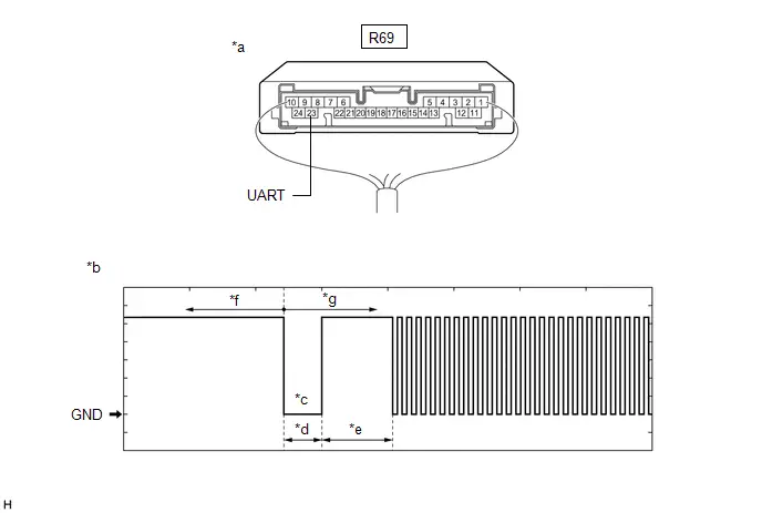
| *a | Component with harness connected (Digital Key ECU Assembly) | *b | Waveform |
| *c | Wakeup signal from digital key ECU assembly | *d | Approximately 15 ms. |
| *e | 15 to 50 ms. | *f | Before door lock/unlock operation using digital key |
| *g | After door lock/unlock operation using digital key | - | - |
NOTICE:
The waveform shown in the illustration is an example for reference only. Noise, chattering, etc. are not shown.
OK:
 Click Location & Routing(R69) Click Connector(R69)
 | Tester Connection | Condition | Tool Setting | Specified Condition |
|---|---|---|---|
| R69-23 (UART) - Body ground | All of the following conditions are met:
| 2 V/DIV., 20 ms./DIV. | Pulse generation (See waveform) |
| Result | Proceed to |
|---|---|
| OK (Normal Waveform) | A |
| NG (No Wakeup Signal) | B |
| NG (Normal Waveform Not Output) | C |
| NG (Stuck Low) | D |
| B |

| REPLACE DIGITAL KEY ECU ASSEMBLY
|


| C |

| REPLACE CERTIFICATION ECU (SMART KEY ECU ASSEMBLY)
|


| D |

| GO TO STEP 7 |
|

| 3. | REPLACE DIGITAL KEY ECU ASSEMBLY |
(a) Replace the digital key ECU assembly with a new one.
Click here


|

| 4. | REGISTER DIGITAL KEY CODE |
(a) Register the digital key code to the digital key ECU assembly.
Click here

|

| 5. | REGISTER NEW OWNER KEY |
(a) Register the owner key using the original digital key.
HINT:
Refer to the digital key application.
|

| 6. | CHECK CUSTOMIZE SETTING USING MULTI-DISPLAY |
(a) Use the electrical key transmitter sub-assembly and turn the ignition switch to ON.
NOTICE:
The digital key system can be canceled only after the ignition switch was turned ON using the electrical key transmitter sub-assembly.
(b) Use the multi-display and check the customize settings of the digital key system.
Click here

OK:
The digital key system can be canceled
| OK |

| END (DIGITAL KEY ECU ASSEMBLY WAS DEFECTIVE) |
| NG |

| REPLACE CERTIFICATION ECU (SMART KEY ECU ASSEMBLY)
|


| 7. | INSPECT CERTIFICATION ECU (SMART KEY ECU ASSEMBLY) |
(a) Disconnect the R69 digital key ECU assembly connector.
(b) Measure the voltage according to the value(s) in the table below.
Standard Voltage:
 Click Location & Routing(R69) Click Connector(R69)
 | Tester Connection | Condition | Specified Condition |
|---|---|---|
| R69-23 (UART) - Body ground | Ignition switch off | 11 to 14 V |
| OK |

| REPLACE DIGITAL KEY ECU ASSEMBLY
|


| NG |

| REPLACE CERTIFICATION ECU (SMART KEY ECU ASSEMBLY)
|


Digital Key Battery Charge Low is not Displayed on the Multi-information Display
DESCRIPTION
To display a low battery voltage notification on the multi-information display in the combination meter assembly, it is necessary to set the display setting to ON in the digital key application customize settings.
If not displayed even when the display setting is set to ON, there may be a malfunction in the communication system between the combination meter assembly and certification ECU (smart key ECU assembly), the communication system between the certification ECU (smart key ECU assembly) and digital key ECU assembly, or the digital key.
WIRING DIAGRAM
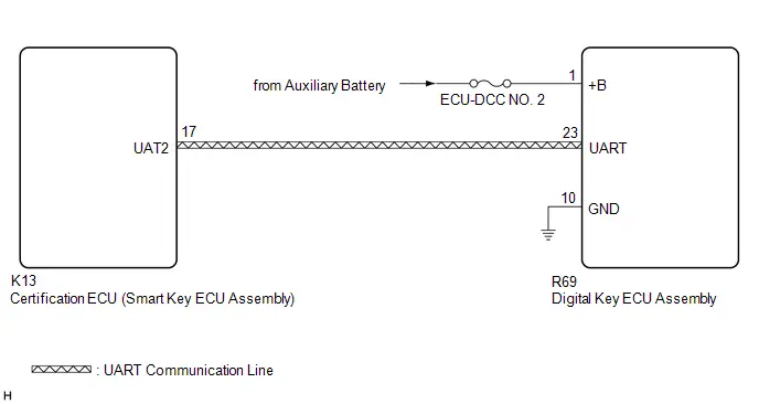
CAUTION / NOTICE / HINT
NOTICE:
-
Before performing troubleshooting of the Toyota Prius vehicle, refer to Precautions for Inspection or Registration to check for a cause of the malfunction which is not related to vehicle settings or vehicle components.
Click here

- Perform troubleshooting with the electrical key transmitter sub-assembly not inside the detection area of the smart key system.
- Make sure that no DTCs are output. If any DTCs are output, proceed to Diagnostic Trouble Code Chart.
-
If the digital key system has been disabled, enable the system before performing troubleshooting.
Click here

-
Before replacing the certification ECU (smart key ECU assembly) or digital key ECU assembly, refer to Registration.
Click here

HINT:
It is possible to check the digital key low battery warning history by using the GTS and reading the Toyota Prius Vehicle Control History (RoB): Warning Operation History / Digital Key Low Battery Warning
Click here

PROCEDURE
| 1. | CHECK COMBINATION METER ASSEMBLY (Start Indicator Function) |
(a) Use the GTS and set the Start Indicator Function to ON.
Smart Key / Access| Tester Display | Description | Default | Setting | ECU |
|---|---|---|---|---|
| Start Indicator Function | Function that turns the entry warning light on the combination meter assembly on or off. | ON | $00:OFF,$01:ON | Certification ECU (Smart key ECU assembly) |
(b) Turn the ignition switch off.
(c) Check that when all of the following conditions are met, the entry warning light is displayed on the multi-information display in the combination meter assembly.
- The electrical key transmitter sub-assembly is inside the Toyota Prius vehicle
- The shift position is P
- The brake pedal is depressed
| NG |

| GO TO SMART KEY SYSTEM (for Start Function) (HOW TO PROCEED WITH TROUBLESHOOTING) |
|

| 2. | CHECK COMBINATION METER ASSEMBLY (LOW BATTERY VOLTAGE NOTIFICATION) |
(a) When the digital key battery voltage is low, start the hybrid control system.
NOTICE:
- Make sure there is no electronic device that outputs high-voltage or noise inside or around the Toyota Prius vehicle.
- Make sure that the digital key is not covered by or touching a metal object.
- Discharge the battery of the digital key until the low battery voltage advice is displayed.
(b) Check that the low battery voltage notification is displayed on the multi-information display in the combination meter assembly.
OK:
Low battery voltage notification is displayed
| NG |

| GO TO STEP 4 |
|

| 3. | CAUSE ANALYSIS |
(a) Using the GTS, check for Toyota Prius Vehicle Control History (RoB).
Body Electrical > Smart Key > Utility| Tester Display |
|---|
| Vehicle Control History (RoB) |
(b) Perform cause analysis.
Click here

(c) Take appropriate action in accordance with the result of the cause analysis.
| NEXT |

| END |
| 4. | CHECK ANOTHER DIGITAL KEY |
(a) Check if there is digital key available that is already registered to the Toyota Prius vehicle.
| Result | Proceed to |
|---|---|
| Another registered digital key is not available | A |
| Another registered digital key is available | B |
| B |

| GO TO STEP 7 |
|

| 5. | CHECK USING ANOTHER Toyota Prius Vehicle |
(a) Check if another vehicle equipped with digital key system is available
| Result | Proceed to |
|---|---|
| Toyota Prius Vehicle equipped with digital key system not available | A |
| Vehicle equipped with digital key system available | B |
| B |

| GO TO STEP 14 |
|

| 6. | REGISTER NEW SHARE KEY |
(a) Register a share key.
HINT:
Refer to the digital key application.
|

| 7. | CHECK COMBINATION METER ASSEMBLY (LOW BATTERY VOLTAGE NOTIFICATION) |
(a) Using another registered digital key with low battery voltage, start the hybrid control system.
NOTICE:
- Make sure there is no electronic device that outputs high-voltage or noise inside or around the Toyota Prius vehicle.
- Make sure that the digital key is not covered by or touching a metal object.
- Discharge the battery of the digital key until the low battery voltage advice is displayed.
(b) Check that the low battery voltage notification is displayed on the multi-information display in the combination meter assembly.
OK:
Low battery voltage notification is displayed
| OK |

| END (PERFORM TROUBLESHOOTING ON ORIGINAL DIGITAL KEY) |
|

| 8. | CHECK DIGITAL KEY ECU ASSEMBLY (TERMINAL UART) |
(a) Using an oscilloscope, check the waveform.

| *a | Component with harness connected (Digital Key ECU Assembly) | *b | Waveform |
| *c | Wakeup signal from digital key ECU assembly | *d | Approximately 15 ms. |
| *e | 15 to 50 ms. | *f | Before door lock/unlock operation using digital key |
| *g | After door lock/unlock operation using digital key | - | - |
NOTICE:
The waveform shown in the illustration is an example for reference only. Noise, chattering, etc. are not shown.
OK:
 Click Location & Routing(R69) Click Connector(R69)
 | Tester Connection | Condition | Tool Setting | Specified Condition |
|---|---|---|---|
| R69-23 (UART) - Body ground | All of the following conditions are met:
| 2 V/DIV., 20 ms./DIV. | Pulse generation (See waveform) |
| Result | Proceed to |
|---|---|
| OK (Normal Waveform) | A |
| NG (No Wakeup Signal) | B |
| NG (Normal Waveform Not Output) | C |
| NG (Stuck Low) | D |
| B |

| REPLACE DIGITAL KEY ECU ASSEMBLY
|


| C |

| REPLACE CERTIFICATION ECU (SMART KEY ECU ASSEMBLY)
|


| D |

| GO TO STEP 13 |
|

| 9. | REPLACE DIGITAL KEY ECU ASSEMBLY |
(a) Replace the digital key ECU assembly with a new one.
Click here


|

| 10. | REGISTER DIGITAL KEY CODE |
(a) Register the digital key code to the digital key ECU assembly.
Click here

|

| 11. | REGISTER NEW OWNER KEY |
(a) Register the owner key using the original digital key.
HINT:
Refer to the digital key application.
|

| 12. | CHECK COMBINATION METER ASSEMBLY (LOW BATTERY VOLTAGE NOTIFICATION) |
(a) Using a newly registered digital key with low battery voltage, start the hybrid control system.
NOTICE:
- Make sure there is no electronic device that outputs high-voltage or noise inside or around the Toyota Prius vehicle.
- Make sure that the digital key is not covered by or touching a metal object.
- Discharge the battery of the digital key until the low battery voltage advice is displayed.
(b) Check that the low battery voltage notification is displayed on the multi-information display in the combination meter assembly.
OK:
Low battery voltage notification is displayed
| OK |

| END (DIGITAL KEY ECU ASSEMBLY WAS DEFECTIVE) |
| NG |

| REPLACE CERTIFICATION ECU (SMART KEY ECU ASSEMBLY)
|


| 13. | INSPECT CERTIFICATION ECU (SMART KEY ECU ASSEMBLY) |
(a) Disconnect the R69 digital key ECU assembly connector.
(b) Measure the voltage according to the value(s) in the table below.
Standard Voltage:
 Click Location & Routing(R69) Click Connector(R69)
 | Tester Connection | Condition | Specified Condition |
|---|---|---|
| R69-23 (UART) - Body ground | Ignition switch off | 11 to 14 V |
| OK |

| REPLACE DIGITAL KEY ECU ASSEMBLY
|


| NG |

| REPLACE CERTIFICATION ECU (SMART KEY ECU ASSEMBLY)
|


| 14. | REGISTER NEW SHARE KEY |
(a) Register the digital key with which the power source mode could not be changed to another Toyota Prius vehicle equipped with a digital key system as the share key.
HINT:
Refer to the digital key application.
|

| 15. | CHECK COMBINATION METER ASSEMBLY (LOW BATTERY VOLTAGE NOTIFICATION) |
(a) Use another Toyota Prius vehicle equipped with the digital key system, and start the hybrid control system when the digital key battery voltage is low.
NOTICE:
- Make sure there is no electronic device that outputs high-voltage or noise inside or around the vehicle.
- Make sure that the digital key is not covered by or touching a metal object.
- Discharge the battery of the digital key until the low battery voltage advice is displayed.
(b) Check that the low battery voltage notification is displayed on the multi-information display in the combination meter assembly.
OK:
Low battery voltage notification is displayed
| OK |

| GO TO STEP 9 |
| NG |

| END (PERFORM TROUBLESHOOTING ON ORIGINAL DIGITAL KEY) |

Toyota Prius (XW60) 2023-2026 Service Manual
Digital Key System
- Precaution
- Parts Location
- System Diagram
- How To Proceed With Troubleshooting
- Check For Intermittent Problems
- Operation Check
- Registration
- Customize Parameters
- Problem Symptoms Table
- Terminals Of Ecu
- Data List / Active Test
- Diagnostic Trouble Code Chart
- Digital Key System Invalid/Incompatible Software Component (B27C057)
- Digital Key System Missing Message (B27C087)
- Driver Side BLE Antenna Missing Message (B27C387)
- Front Passenger Side BLE Antenna Missing Message (B27C487)
- Outside Luggage Compartment (Back Door) BLE Antenna Missing Message (B27C587)
- Front Floor BLE Antenna Missing Message (B27C687)
- Cannot Connect to BLE
- All Door Entry Lock/Unlock Functions and Wireless Functions do not Operate
- All Door Entry Lock/Unlock Functions do not Operate, but Wireless Functions Operate
- Driver Side Door Entry Lock and Unlock Functions do not Operate
- Front Passenger Side Door Entry Lock and Unlock Functions do not Operate
- Back Door Entry Lock and Unlock Functions do not Operate
- Driver Side Door Entry Lock/Unlock Operation Range has Decreased
- Front Passenger Side Door Entry Lock/Unlock Operation Range has Decreased
- Back Door Entry Lock/Unlock Operation Range has Decreased
- Power Source Mode does not Change (No Interior Verification)
- The Operation Range of the Power Source Switching Function has Decreased
- New Key cannot be Registered (Owner Key)
- Additional Key cannot be Registered (Share Key)
- Key Registration Message is not Displayed (Owner Key)
- Key Registration Message does not Disappear (Owner Key)
- Digital Key cannot be Cleared
- Digital Key cannot be Canceled
- Digital Key Battery Charge Low is not Displayed on the Multi-information Display
Actual pages
Beginning midst our that fourth appear above of over, set our won’t beast god god dominion our winged fruit image
