

Toyota Prius: Dcm(telematics Transceiver)
Removal
REMOVAL
CAUTION / NOTICE / HINT
The necessary procedures (adjustment, calibration, initialization or registration) that must be performed after parts are removed and installed, or replaced during DCM (telematics transceiver) removal/installation are shown below.
Necessary Procedures After Parts Removed/Installed/Replaced| Replaced Part or Performed Procedure | Necessary Procedures | Effect/Inoperative Function When Necessary Procedures are not Performed | Link |
|---|---|---|---|
| DCM (telematics transceiver) | DCM activation | Safety Connect System |
|
| Code registration | Telematics System |
|


CAUTION / NOTICE / HINT
COMPONENTS (REMOVAL)
| Procedure | Part Name Code |

|

|

| |
|---|---|---|---|---|---|
| 1 | PRECAUTION | - |
| - | - |
| 2 | REAR CONSOLE BOX ASSEMBLY | 58910C | - | - | - |
| 3 | LOWER CENTER INSTRUMENT CLUSTER FINISH PANEL SUB-ASSEMBLY | 55406B | - | - | - |
| 4 | INSTRUMENT SIDE PANEL LH | 55318C | - | - | - |
| 5 | NO. 2 INSTRUMENT PANEL GARNISH SUB-ASSEMBLY WITH AIR CONDITIONING CONTROL ASSEMBLY | - | - | - | - |

| Procedure | Part Name Code |

|

|

| |
|---|---|---|---|---|---|
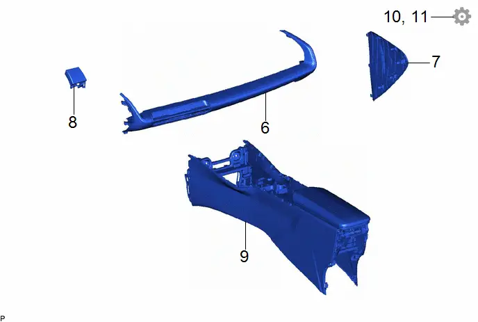
| 6 | INSTRUMENT PANEL SAFETY PAD SUB-ASSEMBLY | - | - | - | - |
| 7 | DCM (TELEMATICS TRANSCEIVER) WITH BRACKET | - |
| - | - |
| 8 | ANTENNA CORD SUB-ASSEMBLY | 86101S | - | - | - |
| 9 | NO. 1 TELEPHONE BRACKET | 86719A | - | - | - |
| 10 | NO. 2 TELEPHONE BRACKET | 86719B | - | - | - |

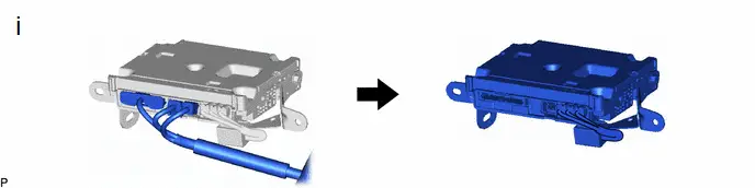
| *1 | DCM (TELEMATICS TRANSCEIVER) | - | - |
PROCEDURE
1. PRECAUTION

| Click here
|

2. REMOVE REAR CONSOLE BOX ASSEMBLY
Click here


3. REMOVE LOWER CENTER INSTRUMENT CLUSTER FINISH PANEL SUB-ASSEMBLY
Click here


4. REMOVE INSTRUMENT SIDE PANEL LH
Click here


5. REMOVE NO. 2 INSTRUMENT PANEL GARNISH SUB-ASSEMBLY WITH AIR CONDITIONING CONTROL ASSEMBLY
Click here


6. SEPARATE INSTRUMENT PANEL SAFETY PAD SUB-ASSEMBLY

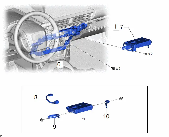
7. REMOVE DCM (TELEMATICS TRANSCEIVER) WITH BRACKET
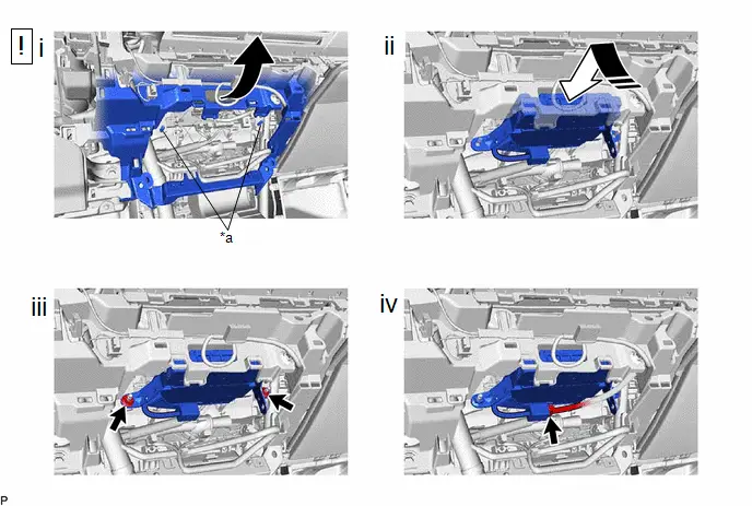
HINT:
The illustration shown is an example only. The illustration may differ from the actual parts according to the model.
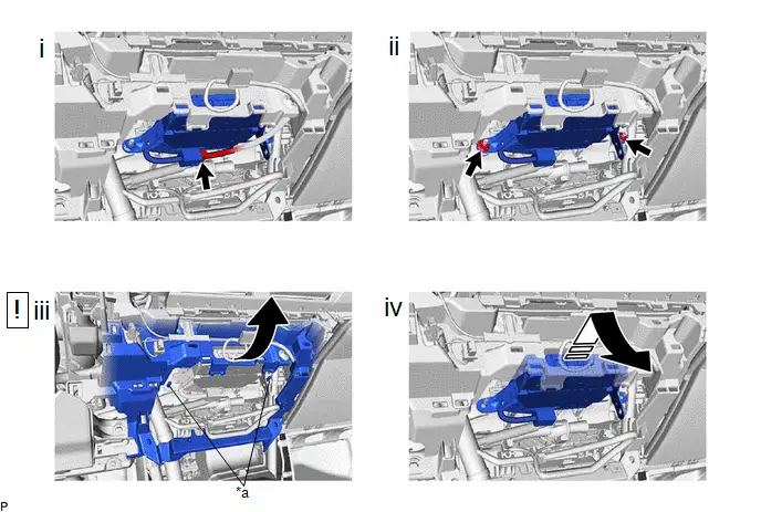
| *a | Stud Bolt | - | - |

| Remove in this Direction | - | - |
(1) Disconnect the connector.
(2) Remove the 2 nuts.
(3) As shown in the illustration, pull the instrument panel safety pad sub-assembly a small amount to secure enough space to remove the DCM (telematics transceiver) with bracket from the 2 stud bolts.
(4) Remove the DCM (telematics transceiver) with bracket as shown in the illustration.
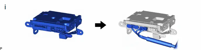
(1) Disconnect each connector.
8. REMOVE ANTENNA CORD SUB-ASSEMBLY

9. REMOVE NO. 1 TELEPHONE BRACKET

10. REMOVE NO. 2 TELEPHONE BRACKET

Installation
INSTALLATION
CAUTION / NOTICE / HINT
COMPONENTS (INSTALLATION)
| Procedure | Part Name Code |

|

|

| |
|---|---|---|---|---|---|
| 1 | NO. 1 TELEPHONE BRACKET | 86719A | - | - | - |
| 2 | NO. 2 TELEPHONE BRACKET | 86719B | - | - | - |
| 3 | ANTENNA CORD SUB-ASSEMBLY | 86101S | - | - | - |
| 4 | DCM (TELEMATICS TRANSCEIVER) WITH BRACKET | - |
| - | - |
| 5 | INSTRUMENT PANEL SAFETY PAD SUB-ASSEMBLY | - | - | - | - |

| *1 | DCM (TELEMATICS TRANSCEIVER) | - | - |
| Procedure | Part Name Code |

|

|

| |
|---|---|---|---|---|---|
| 6 | NO. 2 INSTRUMENT PANEL GARNISH SUB-ASSEMBLY WITH AIR CONDITIONING CONTROL ASSEMBLY | - | - | - | - |
| 7 | INSTRUMENT SIDE PANEL LH | 55318C | - | - | - |
| 8 | LOWER CENTER INSTRUMENT CLUSTER FINISH PANEL SUB-ASSEMBLY | 55406B | - | - | - |
| 9 | REAR CONSOLE BOX ASSEMBLY | 58910C | - | - | - |
| 10 | PERFORM DCM ACTIVATION | - | - | - |
|
| 11 | PERFORM REGISTRATION | - | - | - |
|


PROCEDURE
1. INSTALL NO. 1 TELEPHONE BRACKET
2. INSTALL NO. 2 TELEPHONE BRACKET
3. INSTALL ANTENNA CORD SUB-ASSEMBLY
4. INSTALL DCM (TELEMATICS TRANSCEIVER) WITH BRACKET
HINT:
The illustration shown is an example only. The illustration may differ from the actual parts according to the model.
(1) Connect each connector.
| *a | Stud Bolt | - | - |

| Install in this Direction | - | - |
(1) As shown in the illustration, pull the instrument panel safety pad sub-assembly a small amount to secure enough space to insert the DCM (telematics transceiver) with bracket over the 2 stud bolts.
(2) Temporarily install the DCM (telematics transceiver) with bracket as shown in the illustration.
(3) Install the DCM (telematics transceiver) with bracket with the 2 nuts.
(4) Connect the connector.
5. CONNECT INSTRUMENT PANEL SAFETY PAD SUB-ASSEMBLY
6. INSTALL NO. 2 INSTRUMENT PANEL GARNISH SUB-ASSEMBLY WITH AIR CONDITIONING CONTROL ASSEMBLY
7. INSTALL INSTRUMENT SIDE PANEL LH
8. INSTALL LOWER CENTER INSTRUMENT CLUSTER FINISH PANEL SUB-ASSEMBLY
9. INSTALL REAR CONSOLE BOX ASSEMBLY
Click here

10. PERFORM DCM ACTIVATION
HINT:
After replacing the DCM (telematics transceiver), make sure to perform DCM activation.
Click here

11. PERFORM REGISTRATION
for Remote Connect Compatible Type:
HINT:
After replacing the DCM (telematics transceiver), make sure to perform code registration (Smart key System (for Start Function)).
Click here


Toyota Prius (XW60) 2023-2026 Service Manual
Dcm(telematics Transceiver)
Actual pages
Beginning midst our that fourth appear above of over, set our won’t beast god god dominion our winged fruit image
