

Toyota Prius: Cooling Fan System
Precaution
PRECAUTION
INITIALIZATION
NOTICE:
Make sure to perform the necessary procedures (adjustment, calibration, initialization, or registration) after parts related to the cooling fan system have been removed/installed or replaced.
Click here


Parts Location
PARTS LOCATION
ILLUSTRATION
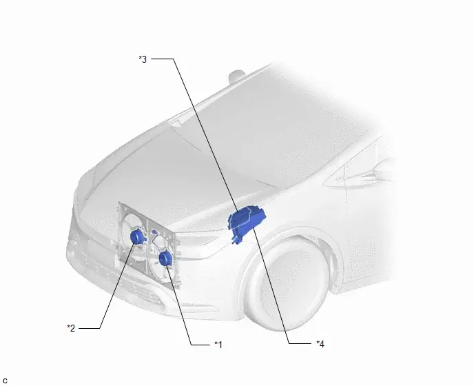
| *1 | COOLING FAN MOTOR LH | *2 | COOLING FAN MOTOR RH |
| *3 | ECM | *4 | NO. 1 ENGINE ROOM RELAY BLOCK AND NO. 1 JUNCTION BLOCK ASSEMBLY - FAN NO. 1 RELAY - FAN NO. 2 RELAY - FAN NO. 3 RELAY |
On-vehicle Inspection
ON-VEHICLE INSPECTION
CAUTION / NOTICE / HINT
CAUTION:
-
When working near the engine room while the engine has started or the power source mode is ignition switch to ON, do not touch the rotating components such as the fan, etc.
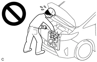
- Touching rotating components such as the fan, etc. could result in your hand or clothing getting caught and pulled in.
-
When the engine is hot, do not touch high-temperature areas such as the engine or exhaust manifold.
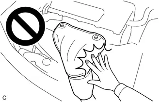
- Touching high-temperature areas such as the engine and exhaust manifold could result in burns.
PROCEDURE
1. INSPECT COOLING FAN SYSTEM OPERATION AT LOW TEMPERATURES
CAUTION:
- When working near the engine room while the engine has started or the power source mode is ignition switch to ON, do not touch the rotating components such as the fan, etc.
- Touching rotating components such as the fan, etc. could result in your hand or clothing getting caught and pulled in.
- When the engine is hot, do not touch high-temperature areas such as the engine or exhaust manifold.
- Touching high-temperature areas such as the engine and exhaust manifold could result in burns.
Pre-procedure1
(a) Check and ensure the following conditions:
(1) Turn the ignition switch off.
(2) The engine coolant temperature is less than 94°C (201°F).
(3) The A/C switch is off.
Procedure1
(b) Turn the ignition switch to ON and wait for approximately 10 seconds. Check that the cooling fans are not operating.
Procedure2
(c) Check that the cooling fans operate when the water temperature sensor connector is disconnected.
Post-procedure1
(d) None
2. INSPECT COOLING FAN SYSTEM OPERATION AT HIGH TEMPERATURES
CAUTION:
- When working near the engine room while the engine has started or the power source mode is ignition switch to ON, do not touch the rotating components such as the fan, etc.
- Touching rotating components such as the fan, etc. could result in your hand or clothing getting caught and pulled in.
- When the engine is hot, do not touch high-temperature areas such as the engine or exhaust manifold.
- Touching high-temperature areas such as the engine and exhaust manifold could result in burns.
Pre-procedure1
(a) Check and ensure the following conditions:
(1) Put the engine in Inspection Mode (Maintenance Mode).
Powertrain > Hybrid Control > Utility| Tester Display |
|---|
| Inspection Mode |
(2) Warm up the engine.
(3) The engine coolant temperature is less than 94°C (201°F).
(4) The A/C switch is off.
Procedure1
(b) Start the engine. Check that the cooling fans are not operating.
Procedure2
(c) Check that the cooling fans start operating when the engine coolant temperature reaches approximately 96°C (205°F).
HINT:
This system can also be checked using the GTS.
Enter the following menus: Powertrain / Engine / Data List / Coolant Temperature.
Powertrain > Engine > Data List| Tester Display |
|---|
| Coolant Temperature |
Post-procedure1
(d) None
Cooling Fan Circuit
DESCRIPTION
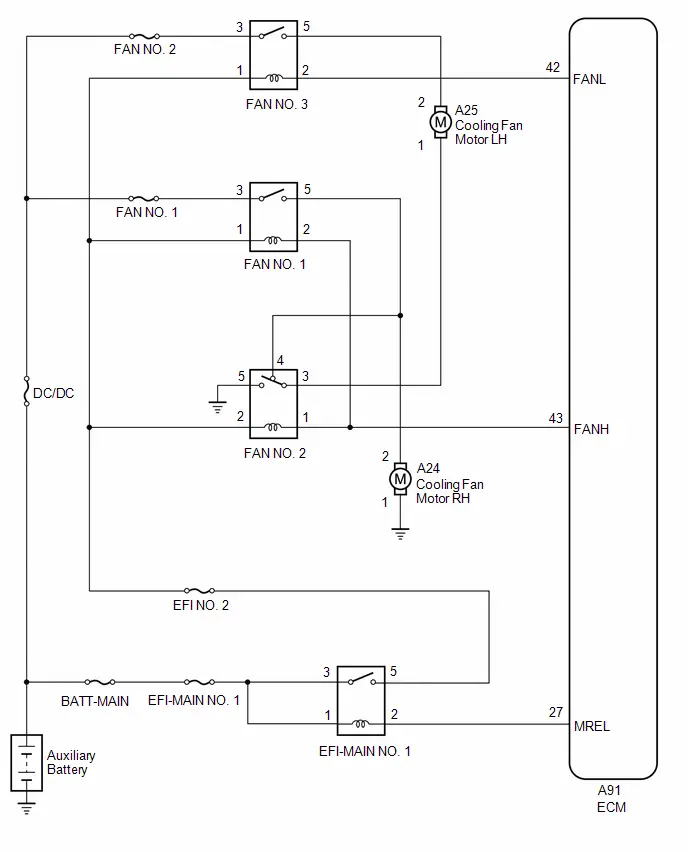
The ECM turns on or off the fan relays using signals calculated from the engine coolant temperature, air conditioning switch (on/off), air conditioning refrigerant pressure, engine speed and vehicle speed signals.
The ECM switches the circuit of the cooling fan motors between series and parallel by turning on or off the fan relays in order to control the speed of the cooling fan motors in two steps.
WIRING DIAGRAM
CAUTION / NOTICE / HINT
NOTICE:
- Inspect the fuses for circuits related to this system before performing the following procedure.
- Before replacing the ECM, refer to Service Bulletin.
PROCEDURE
| 1. | PERFORM ACTIVE TEST USING GTS (CONTROL THE ENGINE COOLING FAN) |
(a) Perform the Active Test according to the display on the GTS.
Powertrain > Engine > Active Test| Tester Display |
|---|
| Control the Engine Cooling Fan |
OK:
| Active Tester Operation | Fan Operation |
|---|---|
| HIGH | Cooling fans high speed operate |
| LOW | Cooling fans low speed operate |
| OFF | Cooling fans stop |
| OK |

| PROCEED TO NEXT SUSPECTED AREA SHOWN IN PROBLEM SYMPTOMS TABLE |
|

| 2. | CHECK HARNESS AND CONNECTOR (FANL - FANH POWER SOURCE) |
(a) Disconnect the A91 ECM connector.
(b) Turn the ignition switch to ON.
(c) Measure the voltage according to the value(s) in the table below.
Standard Voltage:
 Click Location & Routing(A91) Click Connector(A91)
 | Tester Connection | Condition | Specified Condition |
|---|---|---|
| A91-43 (FANH) - Body ground | Ignition switch ON | 11 to 14 V |
| A91-42 (FANL) - Body ground | Ignition switch ON | 11 to 14 V |
| NG |

| GO TO STEP 12 |
|

| 3. | CHECK HARNESS AND CONNECTOR (FAN NO. 1 RELAY AND FAN NO. 3 RELAY POWER SOURCE CIRCUIT) |
(a) Remove the FAN NO. 1 relay and FAN NO. 3 relay from the No. 1 engine room relay block and No. 1 junction block assembly.
(b) Measure the voltage according to the value(s) in the table below.
Standard Voltage:
| Tester Connection | Condition | Specified Condition |
|---|---|---|
| 3 (FAN NO. 1 relay) - Body ground | Always | 11 to 14 V |
| 3 (FAN NO. 3 relay) - Body ground | Always | 11 to 14 V |
| NG |

| REPAIR OR REPLACE HARNESS OR CONNECTOR (FAN NO. 1 RELAY AND FAN NO. 3 RELAY POWER SOURCE CIRCUIT) |
|

| 4. | INSPECT COOLING FAN RELAY (FAN NO. 1, FAN NO. 2 AND FAN NO. 3) |
(a) Inspect the FAN NO. 1 relay, FAN NO. 2 relay and FAN NO. 3 relay.
Click here

| Result | Proceed to |
|---|---|
| OK | A |
| NG (FAN NO. 1 relay) | B |
| NG (FAN NO. 2 relay) | C |
| NG (FAN NO. 3 relay) | D |
| B |

| REPLACE FAN NO. 1 RELAY |
| C |

| REPLACE FAN NO. 2 RELAY |
| D |

| REPLACE FAN NO. 3 RELAY |
|

| 5. | CHECK HARNESS AND CONNECTOR (FAN NO. 2 RELAY - BODY GROUND) |
(a) Remove the FAN NO. 2 relay from the No. 1 engine room relay block and No. 1 junction block assembly.
(b) Measure the resistance according to the value(s) in the table below.
Standard Resistance (Check for Open):
| Tester Connection | Condition | Specified Condition |
|---|---|---|
| 5 (FAN NO. 2 relay) - Body ground | Always | Below 1 Ω |
| NG |

| REPAIR OR REPLACE HARNESS OR CONNECTOR (FAN NO. 2 RELAY - BODY GROUND) |
|

| 6. | INSPECT COOLING FAN MOTOR RH |
(a) Inspect the cooling fan motor RH.
Click here

| NG |

| REPLACE COOLING FAN MOTOR RH |
|

| 7. | CHECK HARNESS AND CONNECTOR (COOLING FAN MOTOR RH - BODY GROUND) |
(a) Disconnect the A24 cooling fan motor RH connector.
(b) Measure the resistance according to the value(s) in the table below.
Standard Resistance (Check for Open):
 Click Location & Routing(A24) Click Connector(A24)
 | Tester Connection | Condition | Specified Condition |
|---|---|---|
| A24-1 - Body ground | Always | Below 1 Ω |
| NG |

| REPAIR OR REPLACE HARNESS OR CONNECTOR (COOLING FAN MOTOR RH - BODY GROUND) |
|

| 8. | CHECK HARNESS AND CONNECTOR (FAN NO. 1 RELAY AND FAN NO. 2 RELAY - COOLING FAN MOTOR RH) |
(a) Disconnect the A24 cooling fan motor RH connector.
(b) Remove the FAN NO. 1 relay and FAN NO. 2 relay from the No. 1 engine room relay block and No. 1 junction block assembly.
(c) Measure the resistance according to the value(s) in the table below.
Standard Resistance (Check for Open):
 Click Location & Routing(A24) Click Connector(A24)
 | Tester Connection | Condition | Specified Condition |
|---|---|---|
| A24-2 - 5 (FAN NO. 1 relay) | Always | Below 1 Ω |
| A24-2 - 4 (FAN NO. 2 relay) | Always | Below 1 Ω |
Standard Resistance (Check for Short):
 Click Location & Routing(A24) Click Connector(A24)
 | Tester Connection | Condition | Specified Condition |
|---|---|---|
| A24-2 or 5 (FAN NO. 1 relay) - Body ground | Always | 10 kΩ or higher |
| A24-2 or 4 (FAN NO. 2 relay) - Body ground | Always | 10 kΩ or higher |
| NG |

| REPAIR OR REPLACE HARNESS OR CONNECTOR (FAN NO. 1 RELAY AND FAN NO. 2 RELAY - COOLING FAN MOTOR RH) |
|

| 9. | INSPECT COOLING FAN MOTOR LH |
(a) Inspect the cooling fan motor LH.
Click here

| NG |

| REPLACE COOLING FAN MOTOR LH |
|

| 10. | CHECK HARNESS AND CONNECTOR (FAN NO. 2 RELAY AND FAN NO. 3 RELAY - COOLING FAN MOTOR LH) |
(a) Disconnect the A25 cooling fan motor LH connector.
(b) Remove the FAN NO. 2 relay and FAN NO. 3 relay from the No. 1 engine room relay block and No. 1 junction block assembly.
(c) Measure the resistance according to the value(s) in the table below.
Standard Resistance (Check for Open):
 Click Location & Routing(A25) Click Connector(A25)
 | Tester Connection | Condition | Specified Condition |
|---|---|---|
| A25-1 - 3 (FAN NO. 2 relay) | Always | Below 1 Ω |
| A25-2 - 5 (FAN NO. 3 relay) | Always | Below 1 Ω |
Standard Resistance (Check for Short):
 Click Location & Routing(A25) Click Connector(A25)
 | Tester Connection | Condition | Specified Condition |
|---|---|---|
| A25-1 or 3 (FAN NO. 2 relay) - Body ground | Always | 10 kΩ or higher |
| A25-2 or 5 (FAN NO. 3 relay) - Body ground | Always | 10 kΩ or higher |
| NG |

| REPAIR OR REPLACE HARNESS OR CONNECTOR (FAN NO. 2 RELAY AND FAN NO. 3 RELAY - COOLING FAN MOTOR LH) |
|

| 11. | CHECK HARNESS AND CONNECTOR (FAN NO. 1 RELAY - FAN NO. 2 RELAY) |
(a) Remove the FAN NO. 1 relay and FAN NO. 2 relay from the No. 1 engine room relay block and No. 1 junction block assembly.
(b) Measure the resistance according to the value(s) in the table below.
Standard Resistance (Check for Open):
| Tester Connection | Condition | Specified Condition |
|---|---|---|
| 1 (FAN NO. 1 relay) - 1 (FAN NO. 2 relay) | Always | Below 1 Ω |
| 2 (FAN NO. 1 relay) - 2 (FAN NO. 2 relay) | Always | Below 1 Ω |
Standard Resistance (Check for Short):
| Tester Connection | Condition | Specified Condition |
|---|---|---|
| 1 (FAN NO. 1 relay) or 1 (FAN NO. 2 relay) - Body ground | Always | 10 kΩ or higher |
| 2 (FAN NO. 1 relay) or 2 (FAN NO. 2 relay) - Body ground | Always | 10 kΩ or higher |
| OK |

| REPLACE ECM |
| NG |

| REPAIR OR REPLACE HARNESS OR CONNECTOR (FAN NO. 1 RELAY AND FAN NO. 2 RELAY - ECM) |
| 12. | INSPECT COOLING FAN RELAY (FAN NO. 1, FAN NO. 2 AND FAN NO. 3) |
(a) Inspect the FAN NO. 1 relay, FAN NO. 2 relay and FAN NO. 3 relay.
Click here

| Result | Proceed to |
|---|---|
| OK | A |
| NG (FAN NO. 1 relay) | B |
| NG (FAN NO. 2 relay) | C |
| NG (FAN NO. 3 relay) | D |
| B |

| REPLACE FAN NO. 1 RELAY |
| C |

| REPLACE FAN NO. 2 RELAY |
| D |

| REPLACE FAN NO. 3 RELAY |
|

| 13. | CHECK HARNESS AND CONNECTOR (FAN NO. 1 RELAY, FAN NO. 2 RELAY AND FAN NO. 3 RELAY POWER SOURCE CIRCUIT) |
(a) Remove the FAN NO. 1 relay, FAN NO. 2 relay and FAN NO. 3 relay from the No. 1 engine room relay block and No. 1 junction block assembly.
(b) Measure the voltage according to the value(s) in the table below.
Standard Voltage:
| Tester Connection | Condition | Specified Condition |
|---|---|---|
| 1 (FAN NO. 1 relay) - Body ground | Always | 11 to 14 V |
| 1 (FAN NO. 2 relay) - Body ground | Always | 11 to 14 V |
| 1 (FAN NO. 3 relay) - Body ground | Always | 11 to 14 V |
| OK |

| REPAIR OR REPLACE HARNESS OR CONNECTOR (FAN NO. 1 RELAY, FAN NO. 2 RELAY AND FAN NO. 3 RELAY - ECM) |
|

| 14. | CHECK HARNESS AND CONNECTOR (FAN NO. 1 RELAY, FAN NO. 2 RELAY AND FAN NO. 3 RELAY - NO. 1 INTEGRATION RELAY) |
(a) Remove the EFI-MAIN No. 1 relay, FAN NO. 1 relay, FAN NO. 2 relay and FAN NO. 3 relay from the No. 1 engine room relay block and No. 1 junction block assembly.
(b) Measure the resistance according to the value(s) in the table below.
Standard Resistance (Check for Open):
| Tester Connection | Condition | Specified Condition |
|---|---|---|
| 1 (FAN NO. 1 relay) - 5 (EFI-MAIN No. 1 relay) | Always | Below 1 Ω |
| 2 (FAN NO. 2 relay) - 5 (EFI-MAIN No. 1 relay) | Always | Below 1 Ω |
| 1 (FAN NO. 3 relay) - 5 (EFI-MAIN No. 1 relay) | Always | Below 1 Ω |
Standard Resistance (Check for Short):
| Tester Connection | Condition | Specified Condition |
|---|---|---|
| 1 (FAN NO. 1 relay) or 5 (EFI-MAIN No. 1 relay) - Body ground | Always | 10 kΩ or higher |
| 2 (FAN NO. 2 relay) or 5 (EFI-MAIN No. 1 relay) - Body ground | Always | 10 kΩ or higher |
| 1 (FAN NO. 3 relay) or 5 (EFI-MAIN No. 1 relay) - Body ground | Always | 10 kΩ or higher |
| NG |

| REPAIR OR REPLACE HARNESS OR CONNECTOR (FAN NO. 1 RELAY, FAN NO. 2 RELAY AND FAN NO. 3 RELAY - NO. 1 INTEGRATION RELAY) |
|

| 15. | INSPECT EFI-MAIN NO.1 RELAY |
(a) Inspect the EFI-MAIN No. 1 relay.
Click here

| NG |

| REPLACE EFI-MAIN NO.1 RELAY |
|

| 16. | CHECK HARNESS AND CONNECTOR (EFI-MAIN NO.1 RELAY POWER SOURCE CIRCUIT) |
(a) Remove the EFI-MAIN No. 1 relay from the No. 1 engine room relay block and No. 1 junction block assembly.
(b) Measure the voltage according to the value(s) in the table below.
Standard Voltage:
| Tester Connection | Condition | Specified Condition |
|---|---|---|
| 3 (EFI-MAIN No. 1 relay) - Body ground | Always | 11 to 14 V |
| NG |

| REPAIR OR REPLACE HARNESS OR CONNECTOR (EFI-MAIN NO.1 RELAY POWER SOURCE CIRCUIT) |
|

| 17. | CHECK HARNESS AND CONNECTOR (EFI-MAIN NO.1 RELAY - BODY GROUND) |
(a) Remove the EFI-MAIN No. 1 relay from the No. 1 engine room relay block and No. 1 junction block assembly.
(b) Measure the resistance according to the value(s) in the table below.
Standard Resistance:
| Tester Connection | Condition | Specified Condition |
|---|---|---|
| 1(EFI-MAIN No. 1 relay) - Body ground | Always | Below 1 Ω |
| NG |

| REPAIR OR REPLACE HARNESS OR CONNECTOR (EFI-MAIN NO.1 RELAY - BODY GROUND) |
|

| 18. | CHECK HARNESS AND CONNECTOR (ECM - EFI-MAIN NO.1 RELAY) |
(a) Disconnect the A91 ECM connector.
(b) Remove the EFI-MAIN No. 1 relay from the No. 1 engine room relay block and No. 1 junction block assembly.
(c) Measure the resistance according to the value(s) in the table below.
Standard Resistance (Check for Open):
 Click Location & Routing(A91) Click Connector(A91)
 | Tester Connection | Condition | Specified Condition |
|---|---|---|
| A91-27 (MREL) - 2 (EFI-MAIN No. 1 relay) | Always | Below 1 Ω |
Standard Resistance (Check for Short):
 Click Location & Routing(A91) Click Connector(A91)
 | Tester Connection | Condition | Specified Condition |
|---|---|---|
| A91-27 (MREL) or 2 (EFI-MAIN No. 1 relay) - Body ground | Always | 10 kΩ or higher |
| OK |

| REPLACE ECM |
| NG |

| REPAIR OR REPLACE HARNESS OR CONNECTOR (ECM - EFI-MAIN NO.1 RELAY) |

Toyota Prius (XW60) 2023-2026 Service Manual
Cooling Fan System
Actual pages
Beginning midst our that fourth appear above of over, set our won’t beast god god dominion our winged fruit image
