

Toyota Prius: Cooling Fan Motor
On-vehicle Inspection
ON-VEHICLE INSPECTION
CAUTION / NOTICE / HINT
CAUTION:
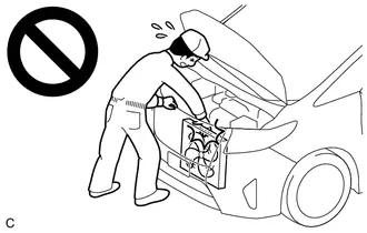
To prevent injury due to contact with an operating cooling fan, keep your hands and clothing away from the cooling fans when inspecting the cooling fan system.
PROCEDURE
1. INSPECT COOLING FAN MOTOR LH
CAUTION:
To prevent injury due to contact with an operating cooling fan, keep your hands and clothing away from the cooling fans when inspecting the cooling fan system.
Pre-procedure1
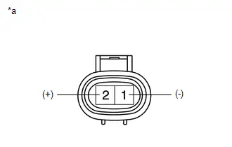
(a) Disconnect the cooling fan motor LH connector.
Procedure1
| (b) Check that the cooling fan motor LH operates smoothly when the auxiliary battery is connected to the cooling fan motor LH connector. |
|
Procedure2
(c) Measure the current while the cooling fan motor LH is operating.
Standard Current:
| Condition | Specified Condition | Result |
|---|---|---|
| Auxiliary battery voltage applied at 20°C (68°F) | 7.4 to 10.9 A | A |
If the result is not as specified, replace the cooling fan motor LH.
Post-procedure1
(d) Connect the cooling fan motor LH connector.
2. INSPECT COOLING FAN MOTOR RH
CAUTION:
To prevent injury due to contact with an operating cooling fan, keep your hands and clothing away from the cooling fans when inspecting the cooling fan system.
Pre-procedure1
(a) Disconnect the cooling fan motor RH connector.
Procedure1
| (b) Check that the cooling fan motor RH operates smoothly when the auxiliary battery is connected to the cooling fan motor RH connector. |
|

Procedure2
(c) Measure the current while the cooling fan motor RH is operating.
Standard Current:
| Condition | Specified Condition | Result |
|---|---|---|
| Auxiliary battery voltage applied at 20°C (68°F) | 7.4 to 10.9 A | A |
If the result is not as specified, replace the cooling fan motor RH.
Post-procedure1
(d) Connect the cooling fan motor RH connector.
Removal
REMOVAL
CAUTION / NOTICE / HINT
The necessary procedures (adjustment, calibration, initialization or registration) that must be performed after parts are removed and installed, or replaced during cooling fan motor LH and cooling fan motor RH removal/installation are shown below.
Necessary Procedures After Parts Removed/Installed/Replaced| Replaced Part or Performed Procedure | Necessary Procedures | Effect/Inoperative Function When Necessary Procedures are not Performed | Link |
|---|---|---|---|
| *1: Even when not replacing the part, it is necessary to perform the specified necessary procedures after installation. | |||
| Front bumper assembly*1 | Front television camera view adjustment | Panoramic View Monitor System |
|
| Advanced Park |
| ||
| Replacement or removal and installation of 2 or more parts:
| Television camera view adjustment | Panoramic View Monitor System |
|


CAUTION / NOTICE / HINT
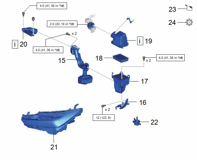
COMPONENTS (REMOVAL)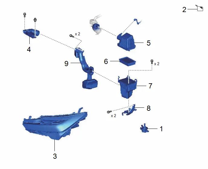
| Procedure | Part Name Code |

|

|

| |
|---|---|---|---|---|---|
| 1 | INVERTER WATER PUMP WITH MOTOR ASSEMBLY | G9040 | - | - | - |
| 2 | DRAIN ENGINE COOLANT (for Engine) | - | - |
| - |
| 3 | HEADLIGHT ASSEMBLY | - | - | - | - |
| 4 | INLET NO. 2 AIR CLEANER | 17752 | - | - | - |
| 5 | AIR CLEANER CAP SUB-ASSEMBLY | 17705 | - | - | - |
| 6 | AIR CLEANER FILTER ELEMENT SUB-ASSEMBLY | 17801 | - | - | - |
| 7 | AIR CLEANER CASE SUB-ASSEMBLY | 17701 | - | - | - |
| 8 | AIR CLEANER BRACKET | 17771A | - | - | - |
| 9 | INLET NO. 1 AIR CLEANER | 17751 | - | - | - |

| Procedure | Part Name Code |

|

|

| |
|---|---|---|---|---|---|
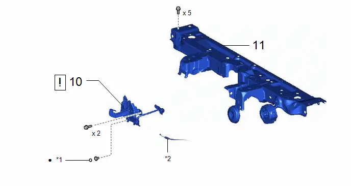
| 10 | HOOD LOCK ASSEMBLY | 53510 |
| - | - |
| 11 | UPPER RADIATOR SUPPORT SUB-ASSEMBLY | 53205 | - | - | - |

| *1 | HOOD LOCK NUT CAP | *2 | HOOD LOCK CONTROL CABLE ASSEMBLY |
| ● | Non-reusable part | - | - |
| Procedure | Part Name Code |

|

|

| |
|---|---|---|---|---|---|
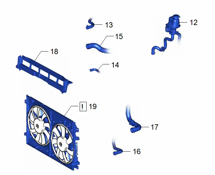
| 12 | INVERTER RESERVE TANK ASSEMBLY | G910GB | - | - | - |
| 13 | NO. 1 WATER BY-PASS HOSE | 16261 | - | - | - |
| 14 | INLET HYBRID RADIATOR HOSE | G922H | - | - | - |
| 15 | NO. 2 RADIATOR HOSE | 16572D | - | - | - |
| 16 | INLET NO. 1 INVERTER COOLING HOSE | G922AA | - | - | - |
| 17 | NO. 1 RADIATOR HOSE | 16571C | - | - | - |
| 18 | NO. 2 RADIATOR AIR GUIDE | 16594A | - | - | - |
| 19 | FAN WITH MOTOR ASSEMBLY | - |
| - | - |

| Procedure | Part Name Code |

|

|

| |
|---|---|---|---|---|---|
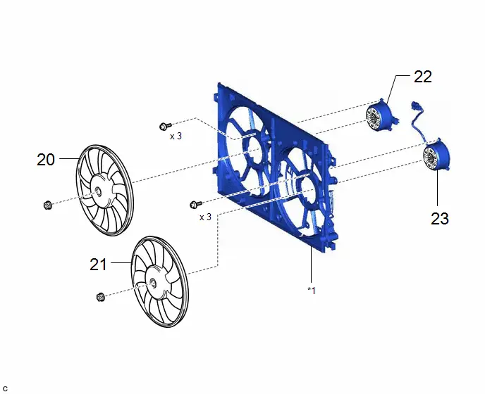
| 20 | FAN RH | 16361J | - | - | - |
| 21 | FAN LH | 16361K | - | - | - |
| 22 | COOLING FAN MOTOR RH | 16363F | - | - | - |
| 23 | COOLING FAN MOTOR LH | 16363G | - | - | - |
| *1 | FAN SHROUD | - | - |
PROCEDURE
1. REMOVE INVERTER WATER PUMP WITH MOTOR ASSEMBLY
Click here

2. DRAIN ENGINE COOLANT (for Engine)
Click here

3. REMOVE HEADLIGHT ASSEMBLY
Click here

4. REMOVE INLET NO. 2 AIR CLEANER
Click here

5. REMOVE AIR CLEANER CAP SUB-ASSEMBLY
Click here

6. REMOVE AIR CLEANER FILTER ELEMENT SUB-ASSEMBLY
Click here

7. REMOVE AIR CLEANER CASE SUB-ASSEMBLY
Click here

8. REMOVE AIR CLEANER BRACKET
Click here

9. REMOVE INLET NO. 1 AIR CLEANER
Click here

10. REMOVE HOOD LOCK ASSEMBLY

| Click here
|


11. REMOVE UPPER RADIATOR SUPPORT SUB-ASSEMBLY

12. DISCONNECT INVERTER RESERVE TANK ASSEMBLY

13. DISCONNECT NO. 1 WATER BY-PASS HOSE

14. DISCONNECT INLET HYBRID RADIATOR HOSE

15. DISCONNECT NO. 2 RADIATOR HOSE

16. DISCONNECT INLET NO. 1 INVERTER COOLING HOSE

17. DISCONNECT NO. 1 RADIATOR HOSE

18. REMOVE NO. 2 RADIATOR AIR GUIDE
19. REMOVE FAN WITH MOTOR ASSEMBLY
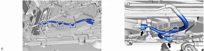
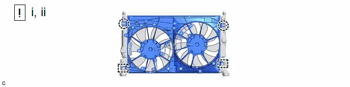
(1) Disengage the 2 claws.
(2) Disengage the 2 guides to remove the fan with motor assembly from the radiator assembly.
NOTICE:
Do not damage the radiator assembly when removing the fan with motor assembly.
20. REMOVE FAN RH

21. REMOVE FAN LH

22. REMOVE COOLING FAN MOTOR RH

23. REMOVE COOLING FAN MOTOR LH


Installation
INSTALLATION
CAUTION / NOTICE / HINT
COMPONENTS (INSTALLATION)
| Procedure | Part Name Code |

|

|

| |
|---|---|---|---|---|---|
| 1 | COOLING FAN MOTOR LH | 16363G | - | - | - |
| 2 | COOLING FAN MOTOR RH | 16363F | - | - | - |
| 3 | FAN LH | 16361K |
| - | - |
| 4 | FAN RH | 16361J |
| - | - |


| *1 | FAN SHROUD | - | - |

| N*m (kgf*cm, ft.*lbf): Specified torque | - | - |
| Procedure | Part Name Code |

|

|

| |
|---|---|---|---|---|---|
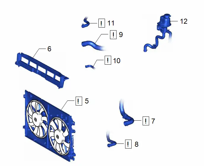
| 5 | FAN WITH MOTOR ASSEMBLY | - |
| - | - |
| 6 | NO. 2 RADIATOR AIR GUIDE | 16594A | - | - | - |
| 7 | NO. 1 RADIATOR HOSE | 16571C |
| - | - |
| 8 | INLET NO. 1 INVERTER COOLING HOSE | G922AA |
| - | - |
| 9 | NO. 2 RADIATOR HOSE | 16572D |
| - | - |
| 10 | INLET HYBRID RADIATOR HOSE | G922H |
| - | - |
| 11 | NO. 1 WATER BY-PASS HOSE | 16261 |
| - | - |
| 12 | INVERTER RESERVE TANK ASSEMBLY | G910GB | - | - | - |


| Procedure | Part Name Code |

|

|

| |
|---|---|---|---|---|---|
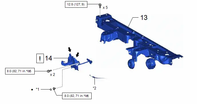
| 13 | UPPER RADIATOR SUPPORT SUB-ASSEMBLY | 53205 | - | - | - |
| 14 | HOOD LOCK ASSEMBLY | 53510 |
| - | - |

| *1 | HOOD LOCK NUT CAP | *2 | HOOD LOCK CONTROL CABLE ASSEMBLY |

| N*m (kgf*cm, ft.*lbf): Specified torque | ● | Non-reusable part |

| MP grease | - | - |
| Procedure | Part Name Code |

|

|

| |
|---|---|---|---|---|---|
| 15 | INLET NO. 1 AIR CLEANER | 17751 | - | - | - |
| 16 | AIR CLEANER BRACKET | 17771A | - | - | - |
| 17 | AIR CLEANER CASE SUB-ASSEMBLY | 17701 | - | - | - |
| 18 | AIR CLEANER FILTER ELEMENT SUB-ASSEMBLY | 17801 | - | - | - |
| 19 | AIR CLEANER CAP SUB-ASSEMBLY | 17705 |
| - | - |
| 20 | INLET NO. 2 AIR CLEANER | 17752 |
| - | - |
| 21 | HEADLIGHT ASSEMBLY | - | - | - | - |
| 22 | INVERTER WATER PUMP WITH MOTOR ASSEMBLY | G9040 | - | - | - |
| 23 | ADD ENGINE COOLANT (for Engine) | - | - |
| - |
| 24 | INSPECT FOR COOLANT LEAK (for Engine) | - | - | - |
|


| N*m (kgf*cm, ft.*lbf): Specified torque | - | - |
PROCEDURE
1. INSTALL COOLING FAN MOTOR LH
Torque:
3.9 N·m {40 kgf·cm, 35 in·lbf}
2. INSTALL COOLING FAN MOTOR RH
Torque:
3.9 N·m {40 kgf·cm, 35 in·lbf}
3. INSTALL FAN LH

| NOTICE: Do not reverse the position of the fan LH and fan RH when installing them. Doing so may damage the parts. |
Torque:
6.3 N·m {64 kgf·cm, 56 in·lbf}
4. INSTALL FAN RH

| NOTICE: Do not reverse the position of the fan LH and fan RH when installing them. Doing so may damage the parts. |
Torque:
6.3 N·m {64 kgf·cm, 56 in·lbf}
5. INSTALL FAN WITH MOTOR ASSEMBLY

(1) Engage the 2 guides.
(2) Engage the 2 claws to install the fan with motor assembly to the radiator assembly.
NOTICE:
Do not damage the radiator assembly when installing the fan with motor assembly.

6. INSTALL NO. 2 RADIATOR AIR GUIDE
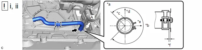
7. CONNECT NO. 1 RADIATOR HOSE
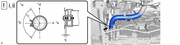
| *a | View A | *b | 110° (Tabs of Clip Installation Area) |
| *c | Paint Mark | *d | Upper Side of Toyota Prius Vehicle |
| *e | Right Side of Vehicle | *f | 2 to 6 mm (0.0787 to 0.236 in.) |
(1) Connect the No. 1 radiator hose to the radiator assembly and slide the clip to secure it.
NOTICE:
- Make sure to slide the No. 1 radiator hose until it contacts the hose stopper of the radiator assembly.
- Make sure that the tabs of the clip are within the area shown in the illustration.
(2) Engage the clamp to connect the No. 1 radiator hose to the fan with motor assembly.
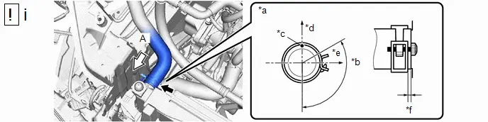
8. CONNECT INLET NO. 1 INVERTER COOLING HOSE
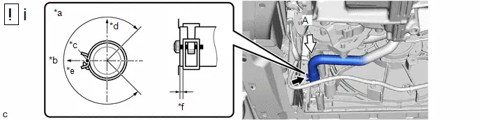
| *a | View A | *b | 270° (Tabs of Clip Installation Area) |
| *c | Paint Mark | *d | Upper Side of Toyota Prius Vehicle |
| *e | Left Side of Vehicle | *f | 2 to 6 mm (0.0787 to 0.236 in.) |
(1) Connect the inlet No. 1 inverter cooling hose to the radiator assembly and slide the clip to secure it.
NOTICE:
- Make sure to slide the inlet No. 1 inverter cooling hose until it contacts the hose stopper of the radiator assembly.
- Make sure that the tabs of the clip are within the area shown in the illustration.
9. CONNECT NO. 2 RADIATOR HOSE
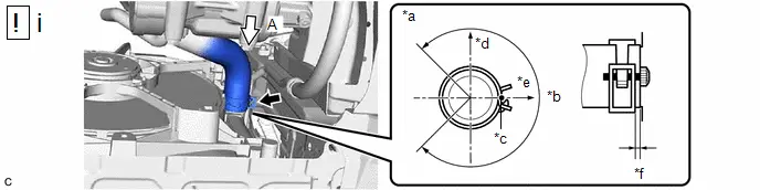
| *a | View A | *b | 270° (Tabs of Clip Installation Area) |
| *c | Paint Mark | *d | Upper Side of Toyota Prius Vehicle |
| *e | Right Side of Vehicle | *f | 2 to 6 mm (0.0787 to 0.236 in.) |
(1) Connect the No. 2 radiator hose to the radiator assembly and slide the clip to secure it.
NOTICE:
- Make sure to slide the No. 2 radiator hose until it contacts the hose stopper of the radiator assembly.
- Make sure that the tabs of the clip are within the area shown in the illustration.
10. CONNECT INLET HYBRID RADIATOR HOSE
| *a | View A | *b | 270° (Tabs of Clip Installation Area) |
| *c | Paint Mark | *d | Upper Side of Toyota Prius Vehicle |
| *e | Right Side of Vehicle | *f | 2 to 6 mm (0.0787 to 0.236 in.) |
(1) Connect the inlet hybrid radiator hose to the radiator assembly and slide the clip to secure it.
NOTICE:
- Make sure to slide the inlet hybrid radiator hose until it contacts the hose stopper of the radiator assembly.
- Make sure that the tabs of the clip are within the area shown in the illustration.
(2) Engage the clamp to connect the inlet hybrid radiator hose to the fan shroud.
11. CONNECT NO. 1 WATER BY-PASS HOSE
| *a | View A | *b | 135° (Tabs of Clip Installation Area) |
| *c | Paint Mark | *d | Upper Side of Toyota Prius Vehicle |
| *e | Right Side of Vehicle | *f | 2 to 6 mm (0.0787 to 0.236 in.) |
(1) Connect the No. 1 water by-pass hose to the radiator assembly and slide the clip to secure it.
NOTICE:
- Make sure to slide the No. 1 water by-pass hose until it contacts the hose stopper of the radiator assembly.
- Make sure that the tabs of the clip are within the area shown in the illustration.
12. CONNECT INVERTER RESERVE TANK ASSEMBLY
13. INSTALL UPPER RADIATOR SUPPORT SUB-ASSEMBLY
Torque:
12.5 N·m {127 kgf·cm, 9 ft·lbf}
14. INSTALL HOOD LOCK ASSEMBLY

| Click here
|

15. INSTALL INLET NO. 1 AIR CLEANER
Click here

16. INSTALL AIR CLEANER BRACKET
Click here

17. INSTALL AIR CLEANER CASE SUB-ASSEMBLY
Click here

18. INSTALL AIR CLEANER FILTER ELEMENT SUB-ASSEMBLY
19. INSTALL AIR CLEANER CAP SUB-ASSEMBLY

| Click here
|

20. INSTALL INLET NO. 2 AIR CLEANER

| Click here
|

21. INSTALL HEADLIGHT ASSEMBLY
Click here

22. INSTALL INVERTER WATER PUMP WITH MOTOR ASSEMBLY
Click here


23. ADD ENGINE COOLANT (for Engine)
Click here

24. INSPECT FOR COOLANT LEAK (for Engine)
Click here


Toyota Prius (XW60) 2023-2026 Service Manual
Cooling Fan Motor
Actual pages
Beginning midst our that fourth appear above of over, set our won’t beast god god dominion our winged fruit image
