

Toyota Prius: Charge Inlet (for Phev Model)
On-vehicle Inspection
ON-VEHICLE INSPECTION
PROCEDURE
1. INSPECT CABLE EV CHARGER LOCK ASSEMBLY
(a) Charging connector lock operation inspection
| (1) Push in the push lifter, perform the door lock operation, and check that the lock pin of the EV charge lock assembly operates. CAUTION: Do not place your hand or fingers under the lock pin while performing this inspection as they may be pinched when the lock pin operates. HINT: Confirm that the auxiliary battery is normal before performing this inspection. Click here
|
|

2. INSPECT INLET AC CHARGER CABLE
| (a) Check that the terminals of the inlet charger cable (charging inlet side) are not bent or deformed. OK: The terminals are not bent or deformed. HINT: If the result is not as specified, replace the inlet charger cable. |
|
Removal
REMOVAL
CAUTION / NOTICE / HINT
The necessary procedures (adjustment, calibration, initialization or registration) that must be performed after parts are removed and installed, or replaced during inlet AC charger cable removal/installation are shown below.
CAUTION:
-
Orange wire harnesses and connectors indicate high-voltage circuits. To prevent electric shock, always follow the procedure described in the repair manual.
Click here

-
To prevent electric shock, wear insulated gloves when working on wire harnesses and components of the high voltage system.
NOTICE:
After turning the ignition switch off, waiting time may be required before disconnecting the cable from the negative (-) auxiliary battery terminal.
Click here

HINT:
When the cable is disconnected / reconnected to the auxiliary battery terminal, systems temporarily stop operating. However, each system has a function that completes learning the first time the system is used.
Items for which learning is completed by driving the Toyota Prius vehicle| Effect/Inoperative Function when Necessary Procedure not Performed | Necessary Procedure | Link |
|---|---|---|
| Front Camera System | Drive the Toyota Prius vehicle straight ahead at 35 km/h (22 mph) or more for 5 seconds or more. |
|

| Effect/Inoperative Function when Necessary Procedure not Performed | Necessary Procedure | Link |
|---|---|---|
|
*1: w/o Power Back Door System
*2: w/ Power Back Door System | ||
| Power Door Lock Control System*1
| Perform door unlock operation with door control switch or electrical key transmitter sub-assembly switch. |
|
| Power Back Door System*2 | Reset back door close position |
|
| Air Conditioning System | After the ignition switch is turned to ON, the servo motor and expansion valve standard position is recognized. | - |


CAUTION / NOTICE / HINT
COMPONENTS (REMOVAL)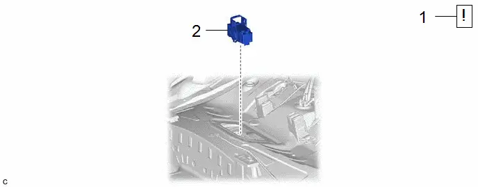
| Procedure | Part Name Code |

|

|

| |
|---|---|---|---|---|---|
| 1 | PRECAUTION | - |
| - | - |
| 2 | SERVICE PLUG GRIP | G3834 | - | - | - |

| Procedure | Part Name Code |

|

|

| |
|---|---|---|---|---|---|
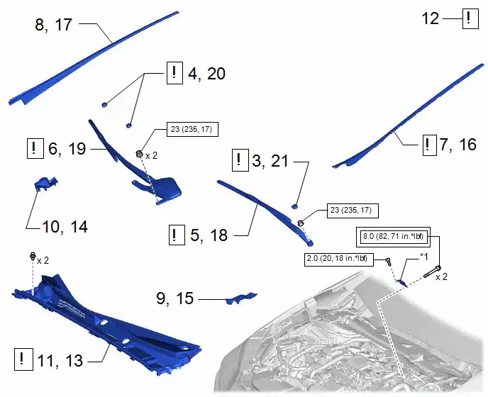
| 3 | FRONT WIPER ARM HEAD CAP | 85292B |
| - | - |
| 4 | SHIELD CAP | 85247 |
| - | - |
| 5 | FRONT WIPER ARM AND BLADE ASSEMBLY LH | - | - | - | - |
| 6 | FRONT WIPER ARM AND BLADE ASSEMBLY RH | - | - | - | - |
| 7 | WINDSHIELD LOWER OUTSIDE MOULDING LH | 75536D |
| - | - |
| 8 | WINDSHIELD LOWER OUTSIDE MOULDING RH | 75535F | - | - | - |
| 9 | COWL WATER EXTRACT SHIELD LH | 55754F | - | - | - |
| 10 | COWL WATER EXTRACT SHIELD RH | 55753D | - | - | - |
| 11 | COWL TOP VENTILATOR LOUVER SUB-ASSEMBLY | 55708 | - | - | - |
| 12 | CHECK TERMINAL VOLTAGE | - |
| - | - |
| 13 | COWL TOP VENTILATOR LOUVER SUB-ASSEMBLY | 55708 |
| - | - |
| 14 | COWL WATER EXTRACT SHIELD RH | 55753D | - | - | - |
| 15 | COWL WATER EXTRACT SHIELD LH | 55754F | - | - | - |
| 16 | WINDSHIELD LOWER OUTSIDE MOULDING LH | 75536D | - | - | - |
| 17 | WINDSHIELD LOWER OUTSIDE MOULDING RH | 77535F | - | - | - |
| 18 | FRONT WIPER ARM AND BLADE ASSEMBLY LH | - |
| - | - |
| 19 | FRONT WIPER ARM AND BLADE ASSEMBLY RH | - |
| - | - |
| 20 | SHIELD CAP | 85247 | - | - | - |
| 21 | FRONT WIPER ARM HEAD CAP | 85292B | - | - | - |


| *1 | Connector Cover Assembly | - | - |

| Tightening torque for "Major areas involving basic Toyota Prius vehicle performance such as moving/turning/stopping": N*m (kgf*cm, ft.*lbf) |

| N*m (kgf*cm, ft.*lbf): Specified torque |
| Procedure | Part Name Code |

|

|

| |
|---|---|---|---|---|---|
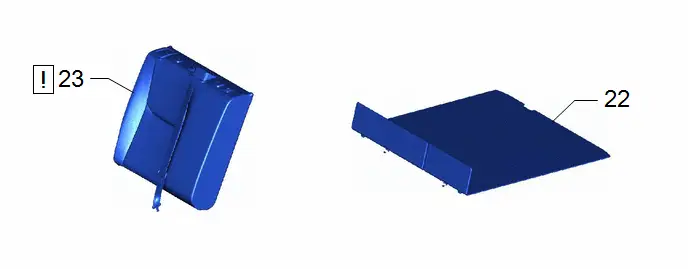
| 22 | DECK BOARD ASSEMBLY | 58410B | - | - | - |
| 23 | REAR SEATBACK ASSEMBLY RH | - |
| - | - |

| Procedure | Part Name Code |

|

|

| |
|---|---|---|---|---|---|
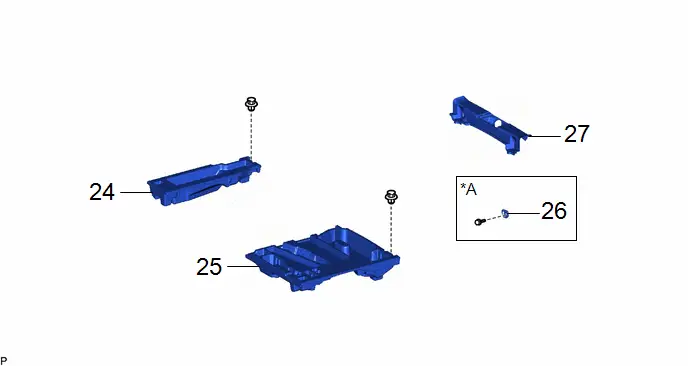
| 24 | DECK FLOOR BOX RH | 64995 | - | - | - |
| 25 | DECK FLOOR BOX LH | 64997 | - | - | - |
| 26 | LUGGAGE HOLD BELT STRIKER ASSEMBLY | 58460D | - | - | - |
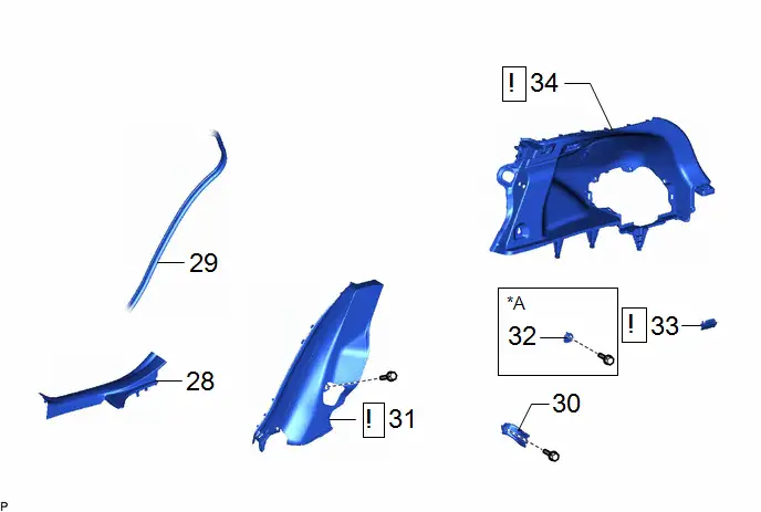
| 27 | REAR DECK TRIM COVER | 64716D | - | - | - |
| *A | for Rear Side | - | - |
| Procedure | Part Name Code |

|

|

| |
|---|---|---|---|---|---|
| 28 | REAR DOOR SCUFF PLATE INSIDE RH | 67917F | - | - | - |
| 29 | REAR DOOR OPENING TRIM WEATHERSTRIP RH | 62331A | - | - | - |
| 30 | REAR SEAT BACK HINGE SUB-ASSEMBLY RH | 71303C | - | - | - |
| 31 | REAR SEAT SIDE GARNISH RH | 62551F |
| - | - |
| 32 | LUGGAGE HOLD BELT STRIKER ASSEMBLY | 58460D | - | - | - |
| 33 | NO. 1 LUGGAGE COMPARTMENT LIGHT ASSEMBLY | 81330 |
| - | - |
| 34 | DECK TRIM SIDE PANEL ASSEMBLY RH | 64730B |
| - | - |


| *A | for RH Side | - | - |
| Procedure | Part Name Code |

|

|

| |
|---|---|---|---|---|---|
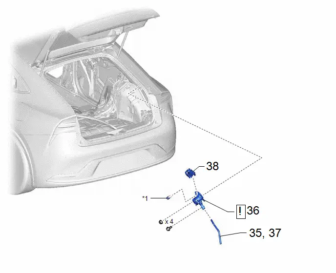
| 35 | DISCONNECT NO. 1 EV CHARGE CONNECTOR DRAIN HOSE | G93B1 | - | - | - |
| 36 | INLET AC CHARGER CABLE | G9081C |
| - | - |
| 37 | REMOVE NO. 1 EV CHARGE CONNECTOR DRAIN HOSE | G93B1 | - | - | - |
| 38 | CABLE EV CHARGER LOCK ASSEMBLY | G90F0A | - | - | - |

| *1 | CONNECTOR PIN | - | - |
PROCEDURE
1. PRECAUTION

| Click here
|

2. REMOVE SERVICE PLUG GRIP
Click here

3. REMOVE FRONT WIPER ARM HEAD CAP

| Click here
|

4. REMOVE SHIELD CAP

| Click here
|

5. REMOVE FRONT WIPER ARM AND BLADE ASSEMBLY LH
Click here

6. REMOVE FRONT WIPER ARM AND BLADE ASSEMBLY RH
Click here

7. REMOVE WINDSHIELD LOWER OUTSIDE MOULDING LH

| Click here
|

8. REMOVE WINDSHIELD LOWER OUTSIDE MOULDING RH
(a) Use the same procedure as for the LH side.
9. REMOVE COWL WATER EXTRACT SHIELD LH
Click here

10. REMOVE COWL WATER EXTRACT SHIELD RH
(a) Use the same procedure as for the LH side.
11. REMOVE COWL TOP VENTILATOR LOUVER SUB-ASSEMBLY
Click here

12. CHECK TERMINAL VOLTAGE

| Click here
|

13. INSTALL COWL TOP VENTILATOR LOUVER SUB-ASSEMBLY

| Click here
|

14. INSTALL COWL WATER EXTRACT SHIELD RH
15. INSTALL COWL WATER EXTRACT SHIELD LH
16. INSTALL WINDSHIELD LOWER OUTSIDE MOULDING LH
Click here

17. INSTALL WINDSHIELD LOWER OUTSIDE MOULDING RH
(a) Use the same procedure as for the LH side.
18. INSTALL FRONT WIPER ARM AND BLADE ASSEMBLY LH

| Click here
|

19. INSTALL FRONT WIPER ARM AND BLADE ASSEMBLY RH

| Click here
|

20. INSTALL SHIELD CAP
21. INSTALL FRONT WIPER ARM HEAD CAP
22. REMOVE DECK BOARD ASSEMBLY
Click here

23. REMOVE REAR SEATBACK ASSEMBLY RH

| Click here
|

24. REMOVE DECK FLOOR BOX RH
Click here

25. REMOVE DECK FLOOR BOX LH
Click here

26. REMOVE LUGGAGE HOLD BELT STRIKER ASSEMBLY (for Rear Side)
Click here

27. REMOVE REAR DECK TRIM COVER
Click here

28. REMOVE REAR DOOR SCUFF PLATE INSIDE RH
(a) Use the same procedure as for the LH side.
Click here

29. DISCONNECT REAR DOOR OPENING TRIM WEATHERSTRIP RH
Click here

30. REMOVE REAR SEAT BACK HINGE SUB-ASSEMBLY RH
(a) Use the same procedure as for the LH side.
Click here

31. REMOVE REAR SEAT SIDE GARNISH RH

| Use the same procedure as for the LH side. Click here
|

32. REMOVE LUGGAGE HOLD BELT STRIKER ASSEMBLY (for RH Side)
(a) Use the same procedure as for the LH side.
Click here

33. REMOVE NO. 1 LUGGAGE COMPARTMENT LIGHT ASSEMBLY

| Click here
|

34. REMOVE DECK TRIM SIDE PANEL ASSEMBLY RH

| Use the same procedure as for the LH side. Click here
|

35. DISCONNECT NO. 1 EV CHARGE CONNECTOR DRAIN HOSE

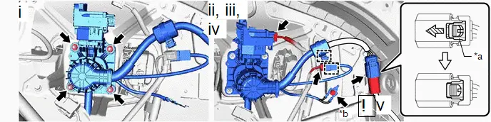
36. REMOVE INLET AC CHARGER CABLE

| CAUTION: Be sure to wear insulated gloves. |
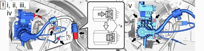
| *a | Green-colored Lock | *b | Earth Terminal |

| Slide | - | - |
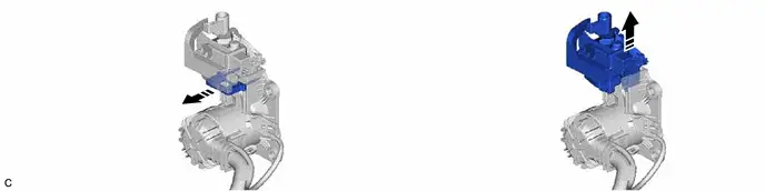
(1) Using a screwdriver, slide the green-colored lock of the connector as shown in the illustration to release it and disconnect the inlet AC charger cable connector.
(2) Disengage the 2 clamps.
(3) Disconnect the 2 inlet AC charger cable connectors.
(4) Remove the bolt and disconnect the earth terminal.
(5) Remove the 4 nuts and inlet AC charger cable.
37. REMOVE NO. 1 EV CHARGE CONNECTOR DRAIN HOSE

38. REMOVE CABLE EV CHARGER LOCK ASSEMBLY
Inspection
INSPECTION
PROCEDURE
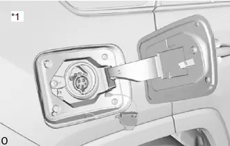
1. INSPECT INLET AC CHARGER CABLE
(a) Visual inspection
NOTICE:
Visual inspection is done with confirming comparisons with a AC charger inlet cable that is known to operate normally.
(1) There are not the damage of the Charge bin location of the AC charger inlet cable, cable damage (disconnection), lock part damage, the damage of the connector or confirms it.
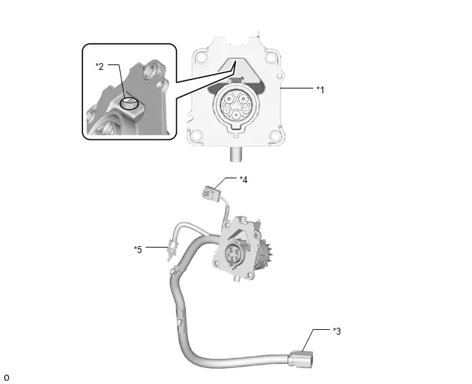
| *1 | Charger opening | *2 | Lock part |
| *3 | Connector (kM1) | *4 | Connector (Mk1) |
| *5 | Earth terminal | - | - |
HINT:
If there is damage in the charger opening that obstructs the charger connector fitting as well as cable damage (disconnection), the lock damaged, or connector damage, replace the AC charger inlet cable.
(2) Confirm there is no foreign objects within the charge opening for the AC charger inlet cable.
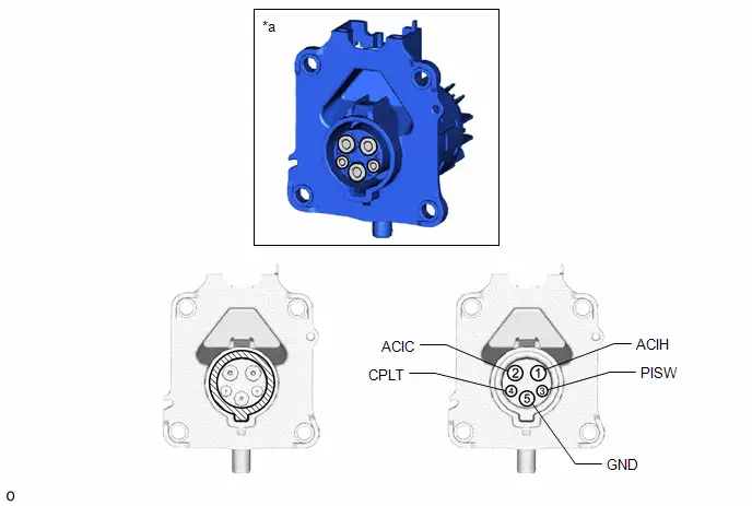
| *a | Inspect the terminal (ACIH, ACIC, GND, CPLT, PISW) | - | - |

| Confirm the region within the terminal |

| Confirm the region within charger opening |
HINT:
If a foreign object that entered within the downward pointing terminals of the AC charging inlet as well as within the charger opening is able to be removed, remove the foreign object and use. If a foreign object in the terminals is not able to be removed, replace the AC charge inlet cable.
(b) Electricity check
(1) Measure the resistance according to the value(s) in the table below.
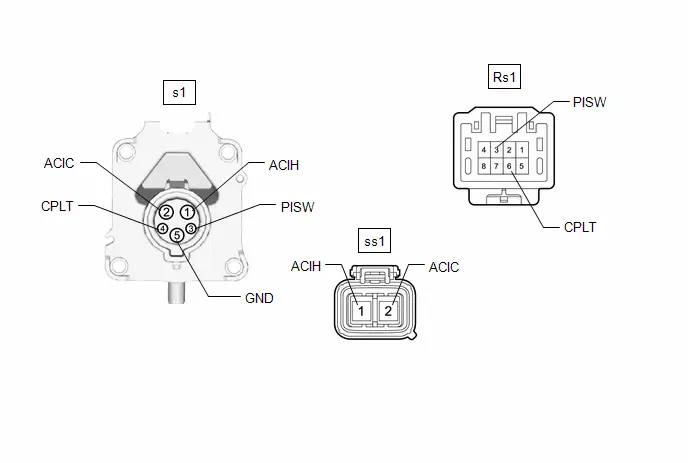
Standard Resistance:
 Click Location & Routing(s1,ss1,Rs1) Click Connector(s1) Click Connector(ss1) Click Connector(Rs1)
 | Tester Connection | Specified Condition |
|---|---|
| s1-1 (ACIH) - ss1-1 (ACIH) | Below 1 Ω |
| s1-2 (ACIC) - ss1-2 (ACIC) | |
| s1-3 (PISW) - Rs1-1 (PISW) | |
| s1-4 (CPLT) - Rs1-6 (CPLT) | |
| s1-5 (GND) - Earth terminal | |
| s1-3 (PISW) - s1-5 (GND) | 2.3 to 3.0 kΩ |
HINT:
If the result is not as specified, replace the inlet AC charger cable.
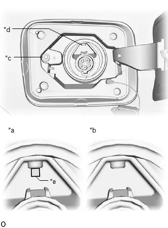
2. INSPECT CABLE EV CHARGER LOCK ASSEMBLY
(a) Visual inspection
| (1) Check that there is no foreign matter on the lock pin of the cable EV charger lock assembly. HINT:
|
|
(2) Check that the lock pin of the cable EV charger lock assembly is not bent, damaged or deformed.
HINT:
If the lock pin of the cable EV charger lock assembly is bent, damaged or deformed, replace the cable EV charger lock assembly.
(b) Check the operation of the lock pin.
(1) Apply auxiliary battery voltage to the terminals of the connector and check that the lock pin operates.
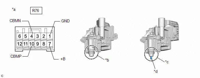
| *a | Component without harness connected (Cable EV Charger Lock Assembly) | *b | Unlocked |
| *c | Locked | *d | Lock Pin |
OK:
| Measurement Condition | Specified Condition |
|---|---|
| Auxiliary Battery positive ( ) → R76-10 (CBMP) and R76-7 ( B) Auxiliary Battery negative (-) → R76-1 (GND) | Locks |
| Auxiliary Battery positive ( ) → R76-4 (CBMN) and R76-7 ( B) Auxiliary Battery negative (-) → R76-1 (GND) | Unlocks |
NOTICE:
-
Apply auxiliary battery voltage for less than 2 or 3 seconds.
- If voltage is applied for an excessive amount of time, the cable EV charger lock assembly may be damaged.
-
Confirm the current position of the lock pin before applying auxiliary battery voltage.
- When the lock pin is in the locked position, perform the unlock operation inspection.
- When the lock pin is in the unlocked position, perform the lock operation inspection.
HINT:
If the result is not as specified, replace the cable EV charger lock assembly.
(c) Inspect the lock pin position detection circuit.
(1) Measure the resistance according to the value(s) in the table below.
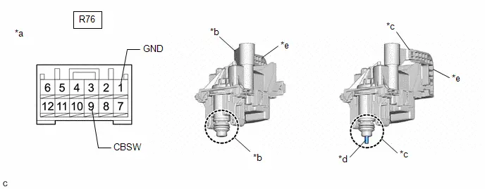
| *a | Component without harness connected (Cable EV Charger Lock Assembly) | *b | Unlocked |
| *c | Locked | *d | Lock Pin |
| *e | Lock Release Lever | - | - |
Standard Resistance:
 Click Location & Routing(R76) Click Connector(R76)
 | Tester Connection | Condition | Specified Condition |
|---|---|---|
| R76-9 (CBSW) - R76-1 (GND) | Locks | Below 1 Ω |
| Unlocks | 10 kΩ or higher |
NOTICE:
The lock release lever moves when the lock pin changes from locked to unlocked or from unlocked to locked.
HINT:
If the result is not as specified, replace the cable EV charger lock assembly.
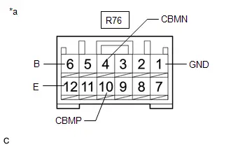
(d) Inspect the power supply circuit of the fuel lid lock with motor assembly
| (1) Measure the resistance according to the value(s) in the table below. Standard Resistance:  Click Location & Routing(R76) Click Connector(R76) Click Location & Routing(R76) Click Connector(R76)
HINT: If the result is not as specified, replace the cable EV charger lock assembly. |
|
Installation
INSTALLATION
CAUTION / NOTICE / HINT
COMPONENTS (INSTALLATION)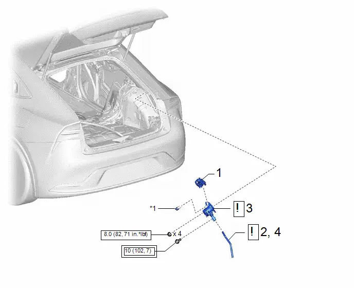
| Procedure | Part Name Code |

|

|

| |
|---|---|---|---|---|---|
| 1 | CABLE EV CHARGER LOCK ASSEMBLY | G90F0A | - | - | - |
| 2 | INSTALL NO. 1 EV CHARGE CONNECTOR DRAIN HOSE | G93B1 |
| - | - |
| 3 | INLET AC CHARGER CABLE | G9081C |
| - | - |
| 4 | CONNECT NO. 1 EV CHARGE CONNECTOR DRAIN HOSE | G93B1 | - | - | - |


| *1 | CONNECTOR PIN | - | - |

| Tightening torque for "Major areas involving basic Toyota Prius vehicle performance such as moving/turning/stopping": N*m (kgf*cm, ft.*lbf) |

| N*m (kgf*cm, ft.*lbf): Specified torque |
| Procedure | Part Name Code |

|

|

| |
|---|---|---|---|---|---|
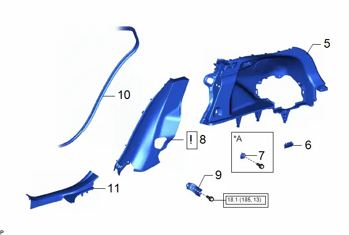
| 5 | DECK TRIM SIDE PANEL ASSEMBLY RH | 64730B | - | - | - |
| 6 | NO. 1 LUGGAGE COMPARTMENT LIGHT ASSEMBLY | 81330 | - | - | - |
| 7 | LUGGAGE HOLD BELT STRIKER ASSEMBLY | 58460D | - | - | - |
| 8 | REAR SEAT SIDE GARNISH RH | 62551F |
| - | - |
| 9 | REAR SEAT BACK HINGE SUB-ASSEMBLY RH | 71303C | - | - | - |
| 10 | REAR DOOR OPENING TRIM WEATHERSTRIP RH | 62331A | - | - | - |
| 11 | REAR DOOR SCUFF PLATE INSIDE RH | 67917F | - | - | - |

| *A | for RH Side | - | - |

| Tightening torque for "Major areas involving basic Toyota Prius vehicle performance such as moving/turning/stopping": N*m (kgf*cm, ft.*lbf) | - | - |
| Procedure | Part Name Code |

|

|

| |
|---|---|---|---|---|---|
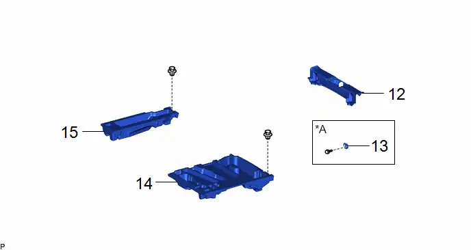
| 12 | REAR DECK TRIM COVER | 64716D | - | - | - |
| 13 | LUGGAGE HOLD BELT STRIKER ASSEMBLY | 58460D | - | - | - |
| 14 | DECK FLOOR BOX LH | 64997 | - | - | - |
| 15 | DECK FLOOR BOX RH | 64995 | - | - | - |
| *A | for Rear Side | - | - |

| Procedure | Part Name Code |

|

|

| |
|---|---|---|---|---|---|
| 16 | REAR SEATBACK ASSEMBLY RH | - |
| - | - |
| 17 | DECK BOARD ASSEMBLY | 58410B | - | - | - |

| Procedure | Part Name Code |

|

|

| |
|---|---|---|---|---|---|
| 18 | SERVICE PLUG GRIP | G3834 | - | - | - |
PROCEDURE
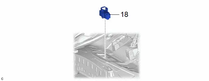
1. INSTALL CABLE EV CHARGER LOCK ASSEMBLY
2. INSTALL NO. 1 EV CHARGE CONNECTOR DRAIN HOSE
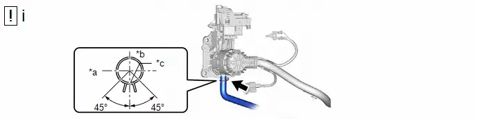
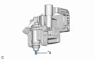
| *a | Front of Toyota Prius Vehicle | *b | RH Side |
| *c | Alignment Mark | - | - |
(1) Install the No. 1 EV charge connector drain hose to the inlet AC charger cable and slide the clip to secure it.
NOTICE:
Make sure that the clip is positioned as shown in the illustration.
3. INSTALL INLET AC CHARGER CABLE

| CAUTION: Be sure to wear insulated gloves. |
| *a | Green-colored Lock | *b | Earth Terminal |

| Slide | - | - |
(1) Install the inlet AC charger cable with the 4 nuts.
Torque:
8.0 N·m {82 kgf·cm, 71 in·lbf}
(2) Connect the earth terminal with the bolt.
Torque:
10 N·m {102 kgf·cm, 7 ft·lbf}
(3) Connect the 2 inlet AC charger cable connectors.
(4) Engage the 2 clamps.
(5) Connect the inlet AC charger cable connector and slide the green-colored lock as shown in the illustration to lock it securely.
4. CONNECT NO. 1 EV CHARGE CONNECTOR DRAIN HOSE
5. INSTALL DECK TRIM SIDE PANEL ASSEMBLY RH
6. INSTALL NO. 1 LUGGAGE COMPARTMENT LIGHT ASSEMBLY
7. INSTALL LUGGAGE HOLD BELT STRIKER ASSEMBLY (for RH Side)
8. INSTALL REAR SEAT SIDE GARNISH RH

| Use the same procedure as for the LH side. Click here
|

9. INSTALL REAR SEAT BACK HINGE SUB-ASSEMBLY RH
(a) Use the same procedure as for the LH side.
Click here

10. CONNECT REAR DOOR OPENING TRIM WEATHERSTRIP RH
11. INSTALL REAR DOOR SCUFF PLATE INSIDE RH
12. INSTALL REAR DECK TRIM COVER
13. INSTALL LUGGAGE HOLD BELT STRIKER ASSEMBLY (for Rear Side)
14. INSTALL DECK FLOOR BOX LH
15. INSTALL DECK FLOOR BOX RH
16. INSTALL REAR SEATBACK ASSEMBLY RH

| Click here
|

17. INSTALL DECK BOARD ASSEMBLY
18. INSTALL SERVICE PLUG GRIP
Click here


Toyota Prius (XW60) 2023-2026 Service Manual
Charge Inlet (for Phev Model)
Actual pages
Beginning midst our that fourth appear above of over, set our won’t beast god god dominion our winged fruit image
